+ All Categories
Home > Documents > D 9.4.4. PowerControlWithWindFarms-Part2-Large Systems

D 9.4.4. PowerControlWithWindFarms-Part2-Large Systems

Date post: 06-Apr-2018
Category:
Upload: ashknaz-oraee
View: 220 times
Download: 0 times
Share this document with a friend
92
 Project funded by the European Commission under the 6th (EC) RTD Framework Programme (2002- 2006) within the framework of the specific research and technological development programme “Integrating and strengthening the European Research Area” Project UpWind Contract No.: 019945 (SES6) “Integrated Wind Turbine Design” Work Package 9: Electrical grid Deliverable D 9.4.4 Evaluation of power control with different electrical and control concept of wind farm Part 2 – Large systems AUTHORS: Anca D. Hansen AFFILIATION: Risø National Laboratory for Sustainable Energy ADDRESS: Frederiksborgvej 399, P.O. Box 49, Building 125, 4000 Roskilde, Denamark TEL.: +45 4677 5073 EMAIL: [email protected] FURTHER AUTHORS: REVIEWER: Poul Sørensen APPROVER: Poul Sørensen
Transcript

8/2/2019 D 9.4.4. PowerControlWithWindFarms-Part2-Large Systems

http://slidepdf.com/reader/full/d-944-powercontrolwithwindfarms-part2-large-systems 1/92


Project funded by the European Commission under the 6th (EC) RTD

Framework Programme (2002- 2006) within the framework of the specific research

and technological development programme “Integrating and strengthening the

European Research Area” 

Project UpWind

Contract No.:019945 (SES6) 

“Integrated Wind Turbine Design”

Work Package 9: Electrical grid

Deliverable D 9.4.4

Evaluation of power controlwith different electrical and control concept of wind farm

Part 2 – Large systems

AUTHORS: Anca D. Hansen

AFFILIATION: Risø National Laboratory for Sustainable Energy

ADDRESS: Frederiksborgvej 399, P.O. Box 49, Building 125, 4000 Roskilde, Denamark

TEL.: +45 4677 5073

EMAIL: [email protected]

FURTHER AUTHORS:

REVIEWER: Poul Sørensen

APPROVER: Poul Sørensen

8/2/2019 D 9.4.4. PowerControlWithWindFarms-Part2-Large Systems

http://slidepdf.com/reader/full/d-944-powercontrolwithwindfarms-part2-large-systems 2/92

 Document Information

DOCUMENT TYPE Report

DOCUMENT NAME: Evaluation of power control with different electrical and control concept of wind farm

DOCUMENT NUMBER:

REVISION: FINAL

REV.DATE: April 2010

CLASSIFICATION: R0 (General Public)

STATUS: FINAL

8/2/2019 D 9.4.4. PowerControlWithWindFarms-Part2-Large Systems

http://slidepdf.com/reader/full/d-944-powercontrolwithwindfarms-part2-large-systems 3/92

Abstract:

This report investigates the impact of wind power in large power systems.

The motivation for this investigation is the ever-increasing wind energy penetration into the

power systems throughout the world. A generic large power system model delivered by theDanish Transmission System Operator EnergiNet.dk is used in the presented study cases.

8/2/2019 D 9.4.4. PowerControlWithWindFarms-Part2-Large Systems

http://slidepdf.com/reader/full/d-944-powercontrolwithwindfarms-part2-large-systems 4/92


Contents

1.  Introduction............................................................................................................... 3 2.  Grid code requirements............................................................................................ 5 

2.1.  Fault ride-through capability ............................................................................ 5 2.2.  Power control capability .................................................................................... 7 

3.  Wind farm models................................................................................................... 10 3.1  Active stall wind turbine.................................................................................. 15 3.2  Doubly-fed induction generator wind turbine............................................... 23 3.3  Multi-pole PMSG wind turbine grid support ................................................ 34 

4.  Generic large power system model........................................................................ 44 5.  Fault ride-through capability................................................................................. 49 

5.1.  ASIG wind turbines’ response to grid faults ................................................. 49 5.2.  DFIG wind turbines’ response to grid faults................................................ 51 3.4  Multi-pole PMSG wind turbines’ response to grid faults ............................ 59 

6.  Power grid support ................................................................................................. 62 6.1 ASIG wind turbine’s power grid support........................................................... 62 6.2 DFIG wind turbines’ power grid support .......................................................... 68 6.3 Multi-pole PMSG wind turbines’ power grid support...................................... 72 

7.  Voltage grid support ............................................................................................... 73 7.1.  ASIG wind turbines’ voltage grid support .................................................... 74 7.2.  DFIG wind turbines’ voltage grid support .................................................... 76 7.3.  Multi-pole PMSG wind turbines’ voltage grid support................................ 81 

8.  Conclusions.............................................................................................................. 85 

8/2/2019 D 9.4.4. PowerControlWithWindFarms-Part2-Large Systems

http://slidepdf.com/reader/full/d-944-powercontrolwithwindfarms-part2-large-systems 5/92

UPWIND 

STATUS, CONFIDENTIALITY AND ACCESSIBILITY 

Status Confidentiality Accessibility 

S0 Approved/Released R0 General public (X) Private web site

S1 Reviewed R1 Restricted to project members Public web site (X)

S2 Pending for review R2 Restricted to European. Commission Paper copy

S3 Draft for comments X R3 Restricted to WP members + PL

S4 Under preparation R4 Restricted to Task members +WPL+PL

PL: Project leader  WPL: Work package leader  TL: Task leader 

8/2/2019 D 9.4.4. PowerControlWithWindFarms-Part2-Large Systems

http://slidepdf.com/reader/full/d-944-powercontrolwithwindfarms-part2-large-systems 6/92

UPWIND 

1. Introduction

The motivation for this investigation is the ever-increasing wind energy penetration into

the power systems throughout the world. Wind power, as most of the renewable energy

sources, is possesses a different role in the power system compared to conventional

power generation units. As long as only single and small wind power units are installed in

the power system, wind power does not influence power system operation and can easily

be integrated. However, when wind power penetration reaches a significant high level

and conventional power production units are substituted, the impact of wind power on thepower system becomes noticeable and must be handled.

The connection of large wind turbines and wind farms to the grid has a large impact on

grid stability. The electrical power system becomes more vulnerable to and dependent on

the wind energy production, and therefore there is an increased concern about the large

wind turbines impact’s on grid stability. This situation, which implies new challenges for

power system operators to ensure reliable and stable grid operation, is directly reflected

in the requirements for grid connections of the wind turbines. These codes are getting

more and more demanding, requiring wind farms to behave more and more as

conventional power plants in the power system and to have thus more responsibility in

network operation. The status of wind turbines is thus changing from being simple energy

sources to having power plant status. This means that sooner or later, they will have to

share some of the duties carried out today by the conventional power plants, namely

behave as active controllable components in the power system, i.e. regulating active and

reactive power and performing frequency and voltage control on the grid.

The increased penetration of wind power has challenged not only the power systemoperators but also different wind turbine manufactures. It has initiated as result an

important research activity directed towards connecting and optimised integration of 

large wind farms within the electrical power grid.

The wind turbine technology and complex wind turbines/wind farms control strategies

have been rapidly developed over the past few years. Today, the wind turbines on the

market mix and match a variety of innovative concepts with proven technologies for both

8/2/2019 D 9.4.4. PowerControlWithWindFarms-Part2-Large Systems

http://slidepdf.com/reader/full/d-944-powercontrolwithwindfarms-part2-large-systems 7/92

UPWIND 

generators and power electronics [1-2]. The survival of these wind turbine technologies is

strongly conditioned by their ability to support the grid, to handle faults on the grid and to

comply with the stringent requirements of the utility companies. These requirements are

determined for wind farms connected to the transmission grid, but they apply both to

onshore and offshore farms.

The main trend of modern wind turbines/wind farms is clearly the variable speed

operation and a grid connection through power electronic interfaces. The presence of 

power electronics inside wind turbines/wind farms offers enlarged control capabilities to

the wind farms to fulfill the grid requirements. During the last years, the market interest

for the fixed speed active stall wind turbine concept has therefore decreased slightly infavour of variable speed wind turbine concepts. One reason for that is that they do not

contain advanced power-electronic components and their control is typically not designed

to support the grid. However, they are still attractive due to their robustness, simplicity

and low cost. The market interest for wind farms with active stall turbines may therefore

increase if their grid support is improved.

Consequently, there is much worldwide research investigating the suitability of 

different wind turbine concepts to comply with the grid utilities requirements [3-4]. The

recent development of large wind farms and their integration into the power system has

furthermore initiated an important research activity in the development of modern

advanced wind farm controllers adapted to each specific wind turbine technology.

This study deals with the impact on large power systems of different wind turbine

concepts like active stall induction generator (ASIG) wind turbines, doubly-fed induction

generator (DFIG) wind turbines and multi-pole permanent magnet synchronous generator

(PMSG) wind turbines, when they are equipped with advanced controllers designed to

comply with the grid code requirements.The present investigation focuses on the most relevant features regarding integration of 

wind power into large power systems, i.e. fault ride through, power control and voltage

support control capabilities of different wind farm concepts. As large power systems have

typically large generator inertia included, frequency stability problem is not a special

issue as in case of small autonomous power systems and it is therefore not addressed in

the report.

8/2/2019 D 9.4.4. PowerControlWithWindFarms-Part2-Large Systems

http://slidepdf.com/reader/full/d-944-powercontrolwithwindfarms-part2-large-systems 8/92

UPWIND 

2. Grid code requirements

The connection of large wind turbines to the grid has a large impact on grid stability. The

increased penetration of wind energy into the power system over the last decade has

therefore led to serious concern about its influence on the dynamic behavior of the power

system. It has resulted in the power system operators revising and increasing the grid

connection requirements in several countries. An overview of the national grid

requirements in countries as Denmark, Ireland, Germany, Great Britain, Spain, Italy,

USA and Canada is also provided in [5].

The main attention in the grid requirements is drawn to the fault ride-through andpower control capabilities of large wind farms.

2.1.  Fault ride-through capability

The fault ride-through requirement has been imposed in order to avoid significant loss

of wind turbine production in the event of grid faults. Up to 7-8 years ago, wind turbines

were only required to be disconnected from the grid when a grid fault was detected, in

order thus to avoid large inrush currents when the voltage recovered. However, with the

increased capacity of wind power in the power system over the years, such a

disconnection of wind turbines could generate control problems of frequency and voltage

in the system, and as worst case a system collapse.

The fault ride-through capability addresses primarily the design of the wind turbine

controller in such a way that the wind turbine is able to remain grid-connected during

grid faults. The fault ride-through demand is also a challenge on how to recover the

voltage after a grid fault. This is especially the case of wind turbines with squirrel cage

induction generator which, by being kept connected to the grid during grid faults mayrequire large currents to energize their induction generators, when the voltage returns

after a while. This can lead to possible violation of grid codes and security standards.

The fault ride-through capability depends on the particular wind turbine technology.

The early generation of wind turbines would disconnect from the grid even during quite

small disturbances as they did not have any fault ride-through capability, in accordance

with the grid codes that were valid at the time of their installation. Modern wind turbines,

8/2/2019 D 9.4.4. PowerControlWithWindFarms-Part2-Large Systems

http://slidepdf.com/reader/full/d-944-powercontrolwithwindfarms-part2-large-systems 9/92

UPWIND 

e.g. those with doubly fed induction generator (DFIG) are able to stay connected during

and after the fault, if they are equipped with a frequency converter protection system.

Furthermore, they are able to support the power system and even improve the behaviour

of local wind turbines with conventional technology, if they are equipped with

appropriate control for grid support [6].

A summary of the fault ride-through requirement in different national grid codes is

given in Table 1. Notice that some national grid codes e.g. Denmark and Ireland have

specific fault ride-through requirements for distribution networks as well as for

transmission ones, while other national grid codes have focus only on the transmission

level. The voltage profiles in these national requirements are given specifying the depthof the voltage drop and the clearance time as well. In some of the grid requirements, as in

Denmark, Íreland and Germany, the definition of the voltage profile is clearly specified

regarding the type of the fault, i.e. symmetric or asymmetric.

Table 1: Summary of national fault ride-through requirements - source [5].

Notice that there is a significant span in the fault ride-through requirements in different

countries. For example, the fault duration varies from 100 msec (in Denmark) to 625

msec (in Ireland, USA and Canada), while the voltage drop level down varies between

25% to even 0% of the nominal value. The Ireland’s code is very demanding regarding

Faultduration

Voltagedrop level

Recoverytime

Voltageprofile

Reactivecurrent

injectionDS 100 msec 25%Ur 1 sec 2, 3-ph no

TS 100 msec 25%Ur 1 sec 1, 2, 3-ph no

Ireland DS/TS 625 msec 15%Ur 3 sec 1, 2, 3- ph no

Germany TS 150 msec 0%Ur 1.5 sec genericUp to100%

SpainTS 500 msec 20%Ur 1 sec generic Up to

100%Italy > 35 kV 500 msec 20%Ur 0.3 sec generic no

USA TS 625 msec 15%Ur 2.3 sec generic noOntario TS 625 msec 15%Ur - - no

Quebec TS 150 msec 0%Ur 0.18 secPositive-sequence

no

no15%Ur 1.2sec genericGreatBritain

TS 140msec

CountryVoltageLevel

Fault ride-through ca ability

Denmark


8/2/2019 D 9.4.4. PowerControlWithWindFarms-Part2-Large Systems

http://slidepdf.com/reader/full/d-944-powercontrolwithwindfarms-part2-large-systems 10/92

UPWIND 

the fault duration, while Denmark has the lowest fault duration with only 100msec.

However, Denmark’s code requires the wind turbine to remain connected to the grid

during successive faults. The German grid code requires the wind turbines to remain

connected to the grid during voltage sags down to 0% from the rated voltage in the PCC

for a duration of 150msec. Moreover, a reactive current injection up to 100% during fault

is required, this requirement being also present in the Spanish grid code.

2.2.  Power control capability

The power control ability means mainly that the wind turbines have to share, for shorter

or longer periods, some of the duties carried out traditionally by conventional power

plants, such as regulating active and reactive power and performing frequency and

voltage control on the grid.

The power control capabilities requirements correspond basically to the wind farm

controllers implemented for the two large Danish wind farms, namely 160MW Horns

Rev wind farm [7] and 165MW Nysted wind farm. These large wind farms are equipped

with capable power control features with remote access. Even though they are consisting

of different wind turbine concepts, having thus different dynamic response to the control

request, their power control behaviour is quite similar.

The power control requirements regard different power system control and stability

aspects:

•  active power/frequency control ability with focus on:

o    primary control – is a fast, automatic global adjustment of power to

frequency.

o  secondary control – is a slower, automatic or manual regional

regulation of the power to the power reference imposed by the systemoperator at any time.

•   reactive power/voltage control ability with focus on voltage regulation and

reactive power capability.

•   dynamic stability with focus on the ability of wind farms to withstand some

specific grid faults without being disconnected.

8/2/2019 D 9.4.4. PowerControlWithWindFarms-Part2-Large Systems

http://slidepdf.com/reader/full/d-944-powercontrolwithwindfarms-part2-large-systems 11/92

UPWIND 

Modern wind farms have to provide advanced grid support [7-8], such as the following

different control functions, illustrated in Figure 1:

•    Balance control – whereby the wind farm production can be adjusted

downwards or upwards, in steps at constant levels.

•    Delta control – whereby the wind farm is ordered to operate with a certain

constant reserve capacity in relation to its momentary possible power

production capacity.

•  Power gradient limiter – which sets how fast the wind farm power production

can be adjusted upwards and downwards.

•   Automatic frequency control – whereby the wind farm must be able to producemore or less active power in order to compensate for a possible deviant

behaviour in the frequency measured in the wind farm point of common

coupling (PCC).

•    Reactive power control – whereby the wind farm is required to produce or

absorb a constant specific amount of reactive power.

•   Automatic voltage control – whereby the wind farm automatically produces or

consumes an amount of reactive power in order to control the voltage in thepoint of common coupling (PCC) of the wind farm.

The power system operators are not only requiring power plant characteristics for the

wind turbines, but also development of suitable dynamic models to assess the wind

generation impact on system stability. Such models play an important role in the design

of national grid codes. Various wind turbine manufactures have also been challenged to

initiate research activities directed towards connection and optimised integration of large

wind farms within the electrical power grid. Risø-DTU National Laboratory has

developed a dynamic simulation model for wind farms [6], [9-10], including both wind

farm controllers, individual wind turbine controllers and the dynamics of the wind

turbines themselves.

8/2/2019 D 9.4.4. PowerControlWithWindFarms-Part2-Large Systems

http://slidepdf.com/reader/full/d-944-powercontrolwithwindfarms-part2-large-systems 12/92

UPWIND 

Figure 2 illustrates the general structure of such wind farm model, which is similar to

what is actually implemented in the Danish Horn Rev and Nysted farms. All the demands

illustrated in Figure 1, can be imposed by the power system operator to the wind farm

controller. The wind farm controller controls the power production from the whole wind

farm by issuing instructions (power references) to each individual wind turbine, each of 

which having its own controller. These instructions are prepared based on the power

system demands, measurements in PCC and on the received information from the wind

turbines about the maximum amount of available power.

Figure 1: Different control functions in modern wind farms.

8/2/2019 D 9.4.4. PowerControlWithWindFarms-Part2-Large Systems

http://slidepdf.com/reader/full/d-944-powercontrolwithwindfarms-part2-large-systems 13/92

UPWIND 

3. Wind farm models

This chapter summarizes the work done on modeling and development of the dynamic

control of the wind farms. Models and control strategies for three different types of wind

farms have been developed, with the aim to optimize the operation of the wind farms

considering their participation in the grid support (fault ride-through, active and reactive

power control, frequency control and voltage control). Models and control for three

different types of wind turbines have been developed:

•  Fixed speed active stall wind turbine concept

•  Variable speed doubly-fed induction generator wind turbine concept

•  Variable speed multi-pole permanent magnet synchronous generator wind

turbine concept

These wind turbine concept models can be used and even extended for the study of 

different aspects, e.g. the assessment of power quality, control strategies, connection of 

the wind turbine at different types of grid and storage systems. Different controlstrategies have been developed and implemented for these wind turbine concepts, their

performance in normal or fault operation being assessed and discussed by means of 

simulations.

A simplified block scheme of the wind turbine models is shown in Figure 3. The basic

block scheme of the wind turbine consists of a wind model, an aerodynamic model, a

transmission system, generator model and a control block model.

Demands Wind farmcontroller

Wind turbinecontroller

Systemoperator

PCC 

meas

PCC 

meas

PCC 

meas

PCC 

meas

U  f 

QP

Powerreferences

Availablepowers

Demands Wind farmcontroller

Wind turbinecontroller

Systemoperator

PCC 

meas

PCC 

meas

PCC 

meas

PCC 

meas

U  f 

QP

Powerreferences

Availablepowers

 Figure 2: The general structure of a wind farm control system.

8/2/2019 D 9.4.4. PowerControlWithWindFarms-Part2-Large Systems

http://slidepdf.com/reader/full/d-944-powercontrolwithwindfarms-part2-large-systems 14/92

UPWIND 

I.  Wind model

The wind model used is described in detail in [11]. The main advantages of this wind

model are the fast computation, reduced memory requirements and the ease of use, either

for variable or constant speed models. This wind speed model is very suitable for

simultaneous simulation of a large number of wind turbines, making it possible to

estimate efficiently the impact of a large wind farm on the power quality.

The structure of the wind model is shown in Figure 4. It provides an equivalent wind

speedeq

v to the aerodynamic model. The wind model includes two sub-models: a hub

wind model and a rotor wind model.

The hub wind model models the fixed-point wind speed at hub height for each wind

turbine. In this hub wind model, the park scale coherence is taken into account in the case

when a whole wind farm is modeled. The second is the rotor wind model, which includes

the averaging effect of the wind speeds over the whole rotor, the rotational sampling

effect, and a tower shadow model. The wind shear is not included in the rotor wind

model, as it only has a small influence on the power fluctuations.

Wind

model

Control model

Aerodynamic

model

Generator

model

bladeθ 

rotor θ 

rotor ω  gen

ω 

eqvrot T  hssT 

ref P

gen

measPω 

u rotor 

Mechanical

model

i rotor 

Wind

model

Control model

Aerodynamic

model

bladeθ 

rotor θ 

rotor ω  gen

ω 

eqvrot T  hssT 

ref P

gen

measPω 

u rotor 

Mechanical

model

i rotor 

Wind

model

Control model

Aerodynamic

model

Generator

model

bladeθ bladeθ 

rotor θ 

rotor θ 

rotor ω 

rotor ω  gen

ω gen

ω 

eqveqvrot T rot T  hssT hssT 

ref Pref P

gen

measPω 

gen

measPω 

u rotor 

Mechanical

model

i rotor 

Wind

model

Control model

Aerodynamic

model

bladeθ bladeθ 

rotor θ 

rotor θ 

rotor ω 

rotor ω  gen

ω gen

ω 

eqveqvrot T rot T  hssT hssT 

ref Pref P

gen

measPω 

gen

measPω 

u rotor 

Mechanical

model

i rotor 


Figure 3: Scheme of wind turbine models.

8/2/2019 D 9.4.4. PowerControlWithWindFarms-Part2-Large Systems

http://slidepdf.com/reader/full/d-944-powercontrolwithwindfarms-part2-large-systems 15/92

UPWIND 

Notice that the rotor positionrot ϑ  is used in the wind model, and therefore this wind

model can be used both variable speed and constant speed.

II.  Mechanical model

In the mechanical model, the emphasis is put only on those parts of the dynamic

structure of the wind turbine that contribute to the interaction with the grid. Therefore

only the drive train is considered in the first place, because this part of the wind turbine

has the most significant influence on the power fluctuations. The other parts of the wind

turbine structure, e.g. tower and the flap bending modes are neglected.

The mechanical model is shown in Figure 5. It is essentially a two mass model

connected by a flexible low-speed shaft characterized by a stiffness k  and a damping c .

The high-speed shaft is assumed stiff. Moreover, an ideal gear with the exchange ratio

1: n gear is included.

Hub wind model

Fixed point wind speed

Wind turbineorWind farms

(park scale wind model)

Rotor wind model

Averaged wind over rotor

Rotational turbulence

Tower shadow

hubuWind

Turbine

rot θ 

Hub wind model

Fixed point wind speed

Wind turbineorWind farms

(park scale wind model)

Rotor wind model

Averaged wind over rotor

Rotational turbulence

Tower shadow

Averaged wind over rotor

Rotational turbulence

Tower shadow

hubuWind

Turbine

rot θ 

eqυ 

Hub wind model

Fixed point wind speed

Wind turbineorWind farms

(park scale wind model)

Rotor wind model

Averaged wind over rotor

Rotational turbulence

Tower shadow

Averaged wind over rotor

Rotational turbulence

Tower shadow

hubuhubuWind

Turbine

rot θ 

rot θ 

Hub wind model

Fixed point wind speed

Wind turbineorWind farms

(park scale wind model)

Rotor wind model

Averaged wind over rotor

Rotational turbulence

Tower shadow

Averaged wind over rotor

Rotational turbulence

Tower shadow

hubuhubuWind

Turbine

rot θ 

rot θ 

eqυ 


Figure 4: Structure of the wind model.

Gearbox

Aerodynamic

Low speedshaft

High speedshaft Generator

1: η 

Gearbox

Aerodynamic

Low speedshaft

High speedshaft

1:

T rot 

 J rot 

c

T shaft 

gear 

θ rot 

 J gen

θ gen

Gearbox

Aerodynamic

Low speedshaft

High speedshaft Generator

1: η 

Gearbox

Aerodynamic

Low speedshaft

High speedshaft

1:

T rot 

 J rot 

c

T shaft 

gear 

θ rot 

 J gen

θ gen


Figure 5: Mechanical model of wind turbine drive train. 

8/2/2019 D 9.4.4. PowerControlWithWindFarms-Part2-Large Systems

http://slidepdf.com/reader/full/d-944-powercontrolwithwindfarms-part2-large-systems 16/92

UPWIND 

The two masses correspond to the large turbine rotor inertiarot 

 J  , representing the

blades and hub, and to the small inertiagen

 J  representing the induction generator. The

generator inertia is actually included in the generator models in DIgSILENT.

The drive train converts the aerodynamic torque rot T  of the rotor into the torque on the

low speed shaftshaft 

T  . The dynamical description of the mechanical model consists of 

three differential equations, namely:

[ ]

[ ]

[ ]2 /  / )(

 / 

 / 

srad  J T T 

srad n

srad 

rot shaft rot rot 

gear 

gen

rot k 

rot rot 

−=

−=

=

ω 

ω ω θ 

ω θ 

&

&

&


(1)

Where  / k rot gen gear  nϑ θ θ = − is the angular difference between the two ends of the

flexible shaft. The mechanical torque on the low speed shaft and the mechanical power

of the generator are:

[ ]

[ ]W n

T P

 Nmk n

cT 

gear 

shaft 

gent 

k gear 

gen

rot shaft 

ω 

θ ω 

ω 

=

+−= )(


(2)

The damping coefficient c is given by:

rot  J k c ξ 2= 

(3)

where ξ  is the damping ratio and can be expressed using the logarithmic decrementsδ  :

22 4 π δ 

δ ξ 

+=

s

s

 (4)

8/2/2019 D 9.4.4. PowerControlWithWindFarms-Part2-Large Systems

http://slidepdf.com/reader/full/d-944-powercontrolwithwindfarms-part2-large-systems 17/92

UPWIND 

The logarithmic decrement is the logarithm of the ratio between the amplitude at the

beginning of the period and the amplitude at the end of the next period of the oscillation:

⎟⎟

 ⎠

 ⎞

⎜⎜

⎝ 

⎛ 

+=

)(

)(ln

 p

st t a

t aδ 

 (5)

where a denotes the amplitude of the signal.

III.  Aerodynamic model

The aerodynamic model is based on tables with the aerodynamic power efficiency( , )

 pC  θ λ  or torque coefficient ( , )

qC  θ λ  , which depend on the pitch angle ϑ  and on the

tip speed ratio λ . This is a quasistatic aerodynamic model which determines the output

aerodynamic torque directly from the input wind speed according to:

2 31( , )

2rot 

rot p

rot rot  

PT R u C    ρ π θ λ  

ω ω = =

 a)

or

3 21 ( , )2rot qT R u C    ρ π θ λ  = 

b)

The aerodynamic model can also include a model for dynamic stall as described in

[12]. The implemented model for dynamic stall is based on Øye’s dynamic stall model

[13].

IV.  Aggregation modeling

Aggregated modeling of large wind farms is commonly used to facilitate the

investigation of the impact of a large wind farm on the dynamics of the power system towhich it is connected. This type of modeling is often used in system studies where the

concern is not on the individual wind turbines but on the impact of the entire farm on the

power system. The advantage of an aggregated model is that it eliminates the need to

develop a detailed model of the wind farm with tens or hundreds of wind turbines and

their interconnections and that it reduces both the complexity of the system and the

computation time substantially.

8/2/2019 D 9.4.4. PowerControlWithWindFarms-Part2-Large Systems

http://slidepdf.com/reader/full/d-944-powercontrolwithwindfarms-part2-large-systems 18/92

UPWIND 

The idea of the aggregation is to represent an entire large wind farm in voltage stability

investigations by one equivalent lumped wind turbine with re-scaled power capacity.

According to [14], the mutual interaction between converter control systems of the wind

turbines equipped with the DFIG can be neglected.

PowerFactory DIgSILENT offers a built-in directly aggregation technique for the

electrical system (i.e. generator, power converter, transformer, capacitor, inductance) of 

the wind turbine [15]: for example, the generator and the transformers, can be modeled

directly by a certain number of parallel machines or transformers, respectively, while the

other electrical components (power converter, capacitance, inductance) and control can

be up scaled accordingly to the increased power flow. The mechanical part of the windfarm aggregated model, namely the shaft model, the aerodynamics and the pitch system,

is modeled as for one individual wind turbine. The mechanical power used as input to the

aggregated generator is then the mechanical output from one turbine multiplied with the

number of turbines in the wind farm.

3.1 Active stall wind turbine

Two versions of models for the active stall controlled wind turbine have been

developed and used at Risø-DTU National Laboratory. The two models reflect the wind

turbine development and according to requirements in e.g. the Danish grid codes.

The first version described in [16] was developed to simulate the first generation of 

active stall / combi stall turbines. Originally, the concept was developed because the

blades became too big for tip breakers, and therefore the whole blade had to become

pitchable. This pitch was further used to remove one of the problems with passive stall,

namely that the maximum power and maximum shaft torque cannot be controlled

actively, since the maximum power of a passive stall controlled wind turbine isinfluenced e.g. by weather conditions (air density) and grid frequency. This first

generation of active stall controlled wind turbines would reduce the pitch activity to a

minimum, and thus had a relatively slow power control. Also reactive power control was

slow, because the capacitor bank used mechanical contactors.

The second model described in [10] was optimized for grid support, and it is in that

respect expected to be quite similar to the Nysted wind turbine. On the active power

8/2/2019 D 9.4.4. PowerControlWithWindFarms-Part2-Large Systems

http://slidepdf.com/reader/full/d-944-powercontrolwithwindfarms-part2-large-systems 19/92

UPWIND 

control side, it responds within a few seconds to changes in the power set point, and on

the reactive power side, it assumes dynamic phase compensation using a thyristor

switched capacitor bank.

Figure 6 illustrates a typical example layout of the active stall wind turbine. The

induction generator, soft starter, the capacitor bank for reactive power compensation and

the step-up transformer are all placed in the nacelle, and thus the transformer is

considered part of the wind turbine. The control of active and reactive power is based on

measured power at the Main Switch Point MSP.

3.1.1  Active stall wind turbine control during normal operation

Wind turbine controller must be able to adjust the wind turbine production to the

power reference demanded by the system operator. In case of normal operation

conditions, the wind turbine has to produce maximum power. In power limitation

operation mode, the wind turbine has to limit its production to the power reference

received from a wind farm controller or directly from the system operator. The power

reference required from the wind turbine can be equal to the rated power of the wind

turbine or less than that. Figure 7 illustrates the power curve and p

C  curves for a 2 MW

active stall wind turbine for different imposed power setpoints.

Notice that by imposing a power set point lower than the designed rated power of the

wind turbine, the wind turbine range with high aerodynamic efficiency is, as expected,

Figure 6: Active stall wind turbine layout including softstarter and capacitor

bank.

8/2/2019 D 9.4.4. PowerControlWithWindFarms-Part2-Large Systems

http://slidepdf.com/reader/full/d-944-powercontrolwithwindfarms-part2-large-systems 20/92

UPWIND 

reduced, while the maximum aerodynamic efficiency is moving toward lower wind

speeds.

The model described in [16] is a traditional power controller designed for a typical

active stall wind turbine. This traditional controller is very slow because it tries to reduce

the pitch activity as much as possible to limit the stress of the pitch system. Such a

controller design is not optimal for grid support, since in this case the wind turbine or the

wind farm is asked to act as a fast active element in the power system. To speed up the

power control, a new active stall power controller is proposed and described in this

chapter. To provide the best grid support, the aim is to use a simpler power controller,

which enables fast control of the wind turbine power to different power setpointsimposed for example by system operator.

Figure 8 illustrates the power control scheme for an active stall wind turbine describedin [10]. A PI controller with antiwind-up ensures a correct active power production from

the wind turbine both in power optimization control and power limitation control modes.

The input of the controller is the error signal between the measured active power at the

Main Switch Point (MSP) and an imposed active power reference. The PI controller

produces the pitch angle referenceref 

θ  , which is further compared to the actual pitch

angle ϑ  and then the error θ Δ is corrected by the servomechanism. In order to get a

0.00

500.00

1000.00

1500.00

2000.00

2500.00

0 .00 5.00 10 .00 15.00 2 0.0 0 25.00

Wind speed [m/s]

   P

    [   k   W

0.00

0.05

0.10

0.15

0.20

0.25

0.30

0.35

0.40

0.45

0.50

Cp

Wind speed [m/s]

Cp

Psetpoint 2MW

Psetpoint 1.5MW

Psetpoint 1MW

Psetpoint 0.5MW

0.00

500.00

1000.00

1500.00

2000.00

2500.00

0.00 5.00 10.00 15.00 20.00 25.00

0.00

0.05

0.10

0.15

0.20

0.25

0.30

0.35

0.40

0.45

0.50

Cp

0.00

500.00

1000.00

1500.00

2000.00

2500.00

0 .00 5.00 10 .00 15.00 2 0.0 0 25.00

Wind speed [m/s]

   P

    [   k   W

0.00

0.05

0.10

0.15

0.20

0.25

0.30

0.35

0.40

0.45

0.50

Cp

0.00

500.00

1000.00

1500.00

2000.00

2500.00

0 .00 5.00 10 .00 15.00 2 0.0 0 25.00

Wind speed [m/s]

   P

    [   k   W

0.00

0.05

0.10

0.15

0.20

0.25

0.30

0.35

0.40

0.45

0.50

Cp

Wind speed [m/s]

Cp

Psetpoint 2MW

Psetpoint 1.5MW

Psetpoint 1MW

Psetpoint 0.5MW

0.00

500.00

1000.00

1500.00

2000.00

2500.00

0.00 5.00 10.00 15.00 20.00 25.00

0.00

0.05

0.10

0.15

0.20

0.25

0.30

0.35

0.40

0.45

0.50

Cp

 Figure 7: Power curve and Cp curve for different wind turbine power setpoints.

8/2/2019 D 9.4.4. PowerControlWithWindFarms-Part2-Large Systems

http://slidepdf.com/reader/full/d-944-powercontrolwithwindfarms-part2-large-systems 21/92

UPWIND 

realistic response in the pitch angle control system, the servomechanism model accounts

for a servo time constantservo

T  and the limitation of both the pitch angle and its gradient.

The output of the actuator is the actual pitch angle of the blades.

The available power of the wind turbine can be monitored at each instant, based on the

wind turbine’s power curve and the filtered wind speed f 

u , as illustrated in Figure 8. The

wind speed is filtered appropriately to avoid unnecessary fluctuations.

In the power optimization control mode, the controller has to maximize the power

production. In this case the difference between the measured power and its reference

value is always positive and is integrated up until the pitch reference angle reaches the

upper limit of the controller. The optimal pitch angle is thus given by the upper limitation

of the controller. This upper limitation is calculated on-line based on an “optimal pitch”

look-up table as a function of the estimated tip speed ratio  / WTR f   R uλ ω = , where

WTRω  is

the wind turbine rotor speed,  R is the rotor radius and f 

u is the filtered wind speed.

In the power limitation control mode the error signal PΔ of the controller is negative

and therefore the pitch angle moves from the upper limitation and starts to actively drive

+

-

θ ref ΔP

K P 

+

θ 

θ 

-

Look-up tableθ opt 

PI controller

Tip Speed Ratio

λ 

Filterpower

Actuator

Gainscheduling

Filter windPower curveAvailablepower u f 

+

-

θ ref ΔP

K P 

+

θ 

θ 

-

Look-up tableθ opt 

PI controller

Tip Speed Ratio

λ 

Filterpower

Actuator

Gainscheduling

Filter windPower curveAvailablepower u f 

+

-

θ ref ΔP

K P 

+

θ 

θ 

-

Look-up tableθ opt 

PI controller

Tip Speed Ratio

λ 

FilterpowerFilterpower

Actuator

Gainscheduling

Filter windPower curveAvailablepower u f 

 Figure 8: Grid support active power control scheme.

8/2/2019 D 9.4.4. PowerControlWithWindFarms-Part2-Large Systems

http://slidepdf.com/reader/full/d-944-powercontrolwithwindfarms-part2-large-systems 22/92

UPWIND 

the measured power to the power reference. Notice that the measured power used in the

error signal is low pass filtered in order to avoid the 3p fluctuations (three times the

rotational frequency) in the power causing the pitch angle to fluctuate with the 3p

frequency as well. This is because it is assumed that the pitch system is too slow to

remove the 3p from the power, and thus the 3p fluctuations in the power would stress the

system unnecessarily.

Compared with the controller presented in [16], the controller presented in [10]

contains an additional gain scheduling control of the pitch angle in order to compensate

for the existing non-linear aerodynamic characteristics. The gain scheduling is necessary

to ensure that the total gain of the system remains unchanged irrespective of theoperational point of the wind turbine. The non-linear aerodynamic characteristics imply

that the effect of pitching on the power varies depending on the operational point. The

goal of the gain scheduling is therefore to change the proportional gain of the controller

 pK  in such a way that the total gain of the system remains unchanged irrespective of the

operational point of the wind turbine. The pitch sensitivity, namely the effect of pitching,

can be expressed mathematically bydP

d θ . The total gain

systemK  of the system can be then

expressed as the proportional gain of the PI controller,P

K  , times the pitch sensitivity of 

the systemdP

d θ , as follows:

.1

0 const d 

dP

dPK 

dPK K  Psystem =⎥⎦

⎤⎢⎣

⎡==

θ θ θ    (6)

where 0K  is a dimensionless constant independent of the operation point.

The total gain of the systemsystem

K  is kept constant by changingP

K  in such a way that

it counteracts the variation of the pitch sensitivitydP

d θ by the reciprocal sensitivity

function1

dP

d θ 

−⎡ ⎤⎢ ⎥⎣ ⎦

, hence:

8/2/2019 D 9.4.4. PowerControlWithWindFarms-Part2-Large Systems

http://slidepdf.com/reader/full/d-944-powercontrolwithwindfarms-part2-large-systems 23/92

UPWIND 

1

0

⎥⎦

⎤⎢⎣

⎡=

θ d 

dPK K 

P

  (7)

The pitch sensitivitydP

d θ of the system depends on the operational point of the wind

turbine. The operation point of the wind turbine is characterized directly by the wind

speed and the power set point and indirectly by the pitch angle and tip speed ratio. The

implementation of the gain scheduling, namely the expression of the non-linear

aerodynamic amplification in the system, is performed on-line based on the simulated

pitch angle and tip speed ratio, according to:

θ π  ρ 

θ  d dC u R

d dP  p

 f 32

21=

  (8)

where f 

u is the filtered wind speed and the power coefficient( , )

 p pC C  θ λ =

depends

on the pitch angle θ  and the tip speed ratio λ . Figure 9 illustrates the pitch sensitivity for

different wind speeds and power set points.

Notice that the pitch sensitivity increases at higher wind speeds. This shows that the

more sensitive the system is (larger pitch angles θ  / higher wind speeds) the smaller the

0.0000

0.0500

0.1000

0.1500

0.2000

0.2500

0.3000

0.3500

0.4000

0.00 5.00 10.00 15.00 20.00 25.00

wind speed [m/s]

Psetpoint 2MW Psetpoint 1.5MW Psetpoint 1MW Psetpoint 0.5MW Psetpoint 0MW

   d   P   /   d

   [   M   W   /   d  e  g   ]

0.0000

0.0500

0.1000

0.1500

0.2000

0.2500

0.3000

0.3500

0.4000

0.00 5.00 10.00 15.00 20.00 25.00

wind speed [m/s]

Psetpoint 2MW Psetpoint 1.5MW Psetpoint 1MW Psetpoint 0.5MW Psetpoint 0MW

   d   P   /   d

   [   M   W   /   d  e  g   ]

 Figure 9: Pitch sensitivity function versus wind speed for different power set

points.

8/2/2019 D 9.4.4. PowerControlWithWindFarms-Part2-Large Systems

http://slidepdf.com/reader/full/d-944-powercontrolwithwindfarms-part2-large-systems 24/92

UPWIND 

gain for the controller should be and vice versa. When the active power set point is

decreased, the pitch sensitivity becomes significant also for lower wind speeds.

3.1.2  Active stall wind turbine control during grid faults

The fault ride-through capability of an ASIG wind farm, and thus its stabilization at a

short circuit fault, can be achieved by reducing the wind turbine power production for

duration of few seconds from the moment of fault occurrence.

In this work, the ASIG wind turbine control strategy during grid faults is implemented

based on [17]. The idea is that during the fault, the ASIG wind turbine normal controller,

illustrated in Figure 8 is switched off and replaced by a control strategy to reduce directly

the mechanical power of the rotor to a predefined level. The ordering of power reduction

is given for example when the monitoring of the grid voltage indicates a fault occurrence.

When the grid fault is cleared, the wind turbine continues running at reduced power for

still few seconds, after which it starts to ramp up the mechanical power of the rotor and

re-establish the control for ASIG wind turbine normal operation conditions.

3.1.3  Active stall wind turbine grid support

Compared with the controller described in [16], the wind turbine controller presentedin [10] contains also an additional controller for the reactive power of the wind turbine.

As illustrated in Figure 6, a capacitor bank is chosen to compensate for the reactive

power absorbed by the induction generator or required by the grid operator. The reactive

power consumption of an induction generator is a function of its loading and it increases

as the active power increases. The power factor of the induction generator at rated load is

usually in the range of 0.85-0.90, which means that the consumption of reactive power is

typically about half of the active power generation. This aspect is taken into account in

the design of the size of the capacitor bank. In order to be able to produce reactive power

to the grid, the size of capacitor bank should thus be larger than the amount of reactive

power consumed by the generator.

In the present implementation, a standard DIgSILENT SVC component is used to

model the capacitor bank instead of a number of individual capacitors as used in earlier

models [12]. The SVC component is a standard component in DIgSILENT and has the

8/2/2019 D 9.4.4. PowerControlWithWindFarms-Part2-Large Systems

http://slidepdf.com/reader/full/d-944-powercontrolwithwindfarms-part2-large-systems 25/92

UPWIND 

advantage of being an effective and easier way to simulate a capacitor bank consisting of 

several capacitor steps of the same size.

The standard SVC component is a combination of a shunt capacitor bank and a

thyristor controlled reactance (TCR). The thyristor controlled reactance is usually used

for a continuous control of reactive power. However, the compensation unit in wind

turbines consists only of capacitors. Thus the TCR part of the standard SVC component

is deactivated in the design of the present SVC control.

A discrete control of SVC is implemented using the dynamic simulation language DSL

of DIgSILENT – see Figure 10. The capacitors in the capacitor bank can be switched on

and off individually by the control system, depending on the load situation, in response tochanges in the reactive power demand.

The difference QΔ between the measured reactive power  MSP

measQ on the low voltage

side of the step-up transformer at the Main Switch Point MSP (see Figure 10) and an

imposed reference reactive power  MSP

ref Q , is used inside a sample-hold block. This block

stores its sampled input signal at the output until the next rising edge of the clock signal

appears. The clock supervises furthermore a register, which memorizes the number of 

capacitors, which have been switched on at the previous clock period. For each clock

period, based on the new updated and the old loading situation, a digital integrator

determines the required number of capacitors.

The control system of SVC has to solve a dilemma: it must be able to switch the

capacitors fast in order to be able to support the grid but on the other hand it should not

attempt to control the 3p fluctuations in the reactive power consumption of the induction

generator due to the wind fluctuations. The traditional wind turbines with directly

connected induction generators are equipped with standard capacitor banks using

Register

Digitalintegrator

Sample-Hold…

SVC

Clock

+- MSP

measQ

 MSP

ref Q

Register

Digitalintegrator

Sample-Hold…

SVC

ClockClock

+- MSP

measQ MSP

measQ

 MSP

ref Q MSP

ref Q

 Figure 10: Designed SVC control for the active stall wind turbine.

8/2/2019 D 9.4.4. PowerControlWithWindFarms-Part2-Large Systems

http://slidepdf.com/reader/full/d-944-powercontrolwithwindfarms-part2-large-systems 26/92

UPWIND 

mechanical contactors, which are typically controlled in intervals of 1-10 minutes. This

control is not fast enough in the case when the turbine has to support the grid. However,

if the capacitors are switched more often using mechanical contactors, the transients due

to the switchings will reduce the lifetime of the capacitors and contactors too much. To

provide a faster control possibility, new wind turbines are using thyristor switches instead

of mechanical contactors, which can reduce the switching transients significantly and

thus make it possible to switch the capacitor much more often without reducing the

lifetime significantly.

As an example, the active stall controlled Bonus wind turbines in Nysted offshore wind

farm in Denmark are equipped with such a dynamic phase compensation unit, usingthyristor switches. Another similar dynamic phase compensation unit was tested on a

wind turbine by Sørensen et.al.[18]. This test concluded that the dynamic phase

compensation technology should not be used to remove the 3p fluctuations in reactive

power, because the transients caused by the many capacitor switchings appeared to cause

more flicker than could be removed by dynamically compensating the 3p reactive power

fluctuations.

The control system of the capacitor bank has thus to switch the capacitors fast in order

to be able to support the grid, but on the other hand it should not attempt to control the 3p

fluctuations in the reactive power consumption of the induction generator.

In the present work, the fast switching of the capacitors is ensured by the clock time 20

ms, while the insensitivity to 3p fluctuations in the wind speed is realized by

implementing a hysteresis in the digital integrator. The output of the digital integrator is

sent directly to the SVC component and thus the required number of capacitors is

switched on or off. The hysteresis has been used instead for a low pass filter in order to

keep a very fast response to large changes in the reactive power reference. This isregarded as important for the ability of the wind turbines to support with voltage control.

3.2 Doubly-fed induction generator wind turbine

A DFIG system is essentially a wound rotor induction generator with slip rings, with the

stator directly connected to the grid and with the rotor interfaced through a back-to-back

partial-scale power converter. The DFIG is doubly fed by means that the voltage on the

8/2/2019 D 9.4.4. PowerControlWithWindFarms-Part2-Large Systems

http://slidepdf.com/reader/full/d-944-powercontrolwithwindfarms-part2-large-systems 27/92

UPWIND 

stator is applied from the grid and the voltage on the rotor is induced by the power

converter. The converter consists of two conventional voltage source converters (rotor-

side converter RSC and grid-side converter GSC) and a common dc-bus, as illustrated in

Figure 11.

The objective of the rotor side converter (RSC) is to control independently the active

power of the generator and the reactive power produced or absorbed from the grid. The

objective of the grid side converter (GRC) is to keep the dc-link voltage constant

regardless of the magnitude and the direction of the rotor power and to guarantee a

converter operation with unity power factor (zero reactive power). This means that the

grid side converter exchanges only active power with the grid, and therefore the

transmission of reactive power from DFIG to the grid is done only through the stator

[19].The behavior of the generator is governed by these converters and their controllers

both in normal and fault conditions.

3.2.1  DFIG wind turbine control during normal operation

Figure 12 sketches the overall control system of a variable speed DFIG wind turbine

implemented in DIgSILENT. Two control levels using different bandwidths can be

distinguished:

•  Doubly-fed induction generator (DFIG) control level

•  Wind turbine control level

GridGear

WRIG

Grid Gear

 AC 

 DC   AC 

 DC 

 RSC  GSC 

Partial scalefrequency converter

GridGridGridGear

WRIG

Grid Gear

 AC 

 DC   AC 

 DC 

 RSC  GSC 

 AC 

 DC   AC 

 DC 

 RSC  GSC 

Partial scalefrequency converter

Grid

 Figure 11: DFIG wind turbine configuration.

8/2/2019 D 9.4.4. PowerControlWithWindFarms-Part2-Large Systems

http://slidepdf.com/reader/full/d-944-powercontrolwithwindfarms-part2-large-systems 28/92

UPWIND 

The DFIG control, with a fast dynamic response, contains the electrical control of the

power converters and of the doubly-fed induction generator. The DFIG control containsthe controllers of the rotor side converter and grid side converter.

The wind turbine control, with slow dynamic response, provides reference signals

both to the pitch system of the wind turbine and to the DFIG control level. It contains two

controllers:

•  Speed controller - has as task to control the generator speed at high wind

speeds i.e. to change the pitch angle in order to prevent the generator speed

becoming too. At low wind speeds, the pitch angle is kept constant to an

optimal value. A gain scheduling control of the pitch angle is implemented in

order to compensate for the existing non-linear aerodynamic characteristics.

•  Maximum power tracking controller – generates the active power reference

signal for the active power control loop, performed by the rotor side

converter controller in DFIG control level. This reference signal is

determined from the predefined characteristic P ω − look-up table, illustrated

in Figure 13, based on filtered measured generator speed. This characteristic

Figure 12: Overall control system of variable speed wind turbine with doubly-fed

induction generator. 

8/2/2019 D 9.4.4. PowerControlWithWindFarms-Part2-Large Systems

http://slidepdf.com/reader/full/d-944-powercontrolwithwindfarms-part2-large-systems 29/92

UPWIND 

is based on aerodynamic data of the wind turbine’s rotor and its points

correspond to the maximum aerodynamic efficiency.

Both the speed controller and the maximum power-tracking controller are active inthe power limitation strategy, while only maximum power tracking controller is active in

the optimization power strategy. In the case of high wind speeds there is a cross coupling

between these two controllers.

Figure 14 illustrates explicitly the speed controller, the maximum power tracking

controller and the rotor side converter controller. The grid side converter controller does

not interact directly with the wind turbine controller, and therefore it is shown as a “black

box”.

Figure 13: Power-omega characteristic used in the maximum power-tracking

controller.

8/2/2019 D 9.4.4. PowerControlWithWindFarms-Part2-Large Systems

http://slidepdf.com/reader/full/d-944-powercontrolwithwindfarms-part2-large-systems 30/92

UPWIND 

In the rotor side converter control, there are two independent control braches, one for

the active power control and the other for reactive power control. Each branch consists of 

2 controllers in cascade.

Notice that all these controllers, except maximum power tracking controller, are

basically PI controllers. Both the speed controller and the maximum power tracking have

as input the filtered measured generator speed. The generator speed is measured and a

low-pass filter is used to avoid that the free-free frequency in the transmission system is

amplified through the control system.

The DFIG control structure, illustrated in Figure 14 , contains the electrical control

of the power converters, which is essential for the DFIG wind turbine behavior both in

normal operation and during fault conditions.

Power converters are usually controlled utilizing vector control techniques [20],

which allow de-coupled control of both active and reactive power. The aim of the RSC is

to control independently the active and reactive power on the grid, while the GSC has to

keep the dc-link capacitor voltage at a set value regardless of the magnitude and the

direction of the rotor power and to guarantee a converter operation with unity power

Figure 14: DFIG wind turbine control during normal operation.

8/2/2019 D 9.4.4. PowerControlWithWindFarms-Part2-Large Systems

http://slidepdf.com/reader/full/d-944-powercontrolwithwindfarms-part2-large-systems 31/92

UPWIND 

factor (zero reactive power). As illustrated in Figure 14, both RSC and GSC are

controlled by a two stage controller. The first stage consists of very fast current

controllers regulating the rotor currents to reference values that are specified by a slower

power controller (second stage).

The control performance of the DFIG is very good in normal grid conditions. DFIG

control can, within limits, hold the electrical power constant in spite of fluctuating wind,

storing thus temporarily the rapid fluctuations in power as kinetic energy.

The active and reactive power set-point signals for the second stage controllers of the

converters in Figure 14 are depending on the wind turbine operational mode (normal or

fault operation) signals. For example, in normal operation:The active power set-point grid 

ref P for the rotor-side converter is defined by the

maximum power tracking point (MPT) look-up table. The reactive power set-point grid 

ref Q  

for the rotor-side converter can be set to a certain value or to zero according to whether or

not the DFIG is required to contribute with reactive power.

The grid-side converter is reactive neutral (i.e. 0GSC 

ref Q = ) in normal operation. This

means that, in normal operation, the GSC exchanges with the grid only active power, and

therefore the transmission of reactive power from DFIG to the grid is done only through

the stator. The dc-voltage set-point signaldc

U  is set to a constant value, independent on

the wind turbine operation mode.

The use of the partial-scale converter to the generator’s rotor makes DFIG concept

on one hand attractive from an economical point of view. On the other hand, this

converter arrangement requires advanced protection system, as it is very sensitive to

disturbances on the grid.

3.2.2  DFIG wind turbine control during grid fault operation

The grid fault is affecting both the mechanical and the electrical part of the wind

turbine. During a grid fault, voltage and power at the wind turbine terminal drop and thus

the power in the DFIG drops, too. This results in an acceleration of turbine and generator,

which is counteracted by the speed controller, i.e. by the pitch angle control, which thus

8/2/2019 D 9.4.4. PowerControlWithWindFarms-Part2-Large Systems

http://slidepdf.com/reader/full/d-944-powercontrolwithwindfarms-part2-large-systems 32/92

UPWIND 

serves as an over speed protection. Moreover, when the electrical power drops the drive

train will start to oscillate.

During grid faults, the electrical torque is significantly reduced, and therefore the

drive train system acts like a torsion spring that gets untwisted. Due to the torsion spring

characteristic of the drive train, the mechanical torque, the aerodynamical torque and thus

the generator speed start to oscillate with the so-called free-free frequency:

eq

osc J 

k  f  ⋅=

π 2

1


where Jeq is the equivalent inertia of the drive train model, determined by:

gengear rot 

gengear rot 

eq J n J 

 J n J  J 

⋅+

⋅⋅=2

2


As these torsional oscillations may influence the converter operation both during grid

faults and a short while after the grid faults have been removed, their modeling by using

at least a two-mass model for the drive train system is essential. Furthermore, these

torsional oscillations can even be excited and become undamped at a fast converter

control [21]. Due to this reason a damping controller is implemented as shown in Figure

15, which actively damps any torsional oscillations of the drive train and preventsinstability of the system and substantially reduces the mechanical stresses of the turbine.

Without any protection system, the concern in DFIG is usually the fact that large grid

disturbances can lead to large fault currents in the stator due to the stator’s direct

connection to the grid. Because of the magnetic coupling between the stator and the rotor

and of the laws of flux conservation, the stator disturbance is further transmitted to the

rotor. High voltages are thus induced in the rotor windings that on their turn cause

excessive currents in the rotor as well. Furthermore, the surge following the fault includes

a “rush” of power from the rotor terminals towards the converter.

Since the stator-rotor ratio of the DFIG is designed according to the desired variable

speed range, in the case of grid faults it might not be possible to achieve the desired rotor

voltage in order to control the high rotor currents. This means that the converter reaches

fast its limits and as a consequence, it loses the control of the generator during the grid

fault [6]. As the grid voltage drops in the fault moment, the GSC is not able to transfer

8/2/2019 D 9.4.4. PowerControlWithWindFarms-Part2-Large Systems

http://slidepdf.com/reader/full/d-944-powercontrolwithwindfarms-part2-large-systems 33/92

UPWIND 

the power from the RSC further to the grid and therefore the additional energy goes into

charging the dc bus capacitor, i.e. dc bus voltage rises rapidly.

A protection system of the DFIG converter is thus necessary to break the high

currents and the uncontrollable energy flow through the RSC to the dc-link and thus to

minimize the effects of possible abnormal operating conditions. The protection system

monitors usually different signals, such as the rotor current, the dc-link voltage and when

at least one of the monitored signals exceeds its respective relay settings, the protection is

activated.

A simple protection method of the DFIG under grid faults is to short circuit the rotor

through a device called crowbar. The crowbar protection is external rotor impedance,coupled via the slip rings to the generator rotor instead of the converter. The function of 

the crowbar is to limit the rotor current.

When the crowbar is triggered, the rotor is short circuited over the crowbar

impedance, the rotor-side converter (RSC) is disabled and therefore the DFIG behaves as

a conventional squirrel cage induction generator (SCIG) with an increased rotor

resistance. The independent controllability of active and reactive power gets thus

unfortunately lost. Since the grid-side converter (GSC) is not directly coupled to the

generator windings, there is no need to disable this converter, too. The GSC can therefore

be used as a STATCOM to produce reactive power (limited however by its rating) during

grid faults.

An increased crowbar resistance improves the torque characteristic and reduces the

reactive power demand of the generator at a certain speed [22]. By the addition of the

external resistance (crowbar resistance) in the rotor circuit during grid faults, the pull-out

torque of the SCIG generator is moved into the range of higher speeds. The dynamic

stability of the SCIG generator is thus improved by increasing the external resistance[21].

In normal operation the active power set-point grid 

ref P for the RSC control is defined

by the maximum power tracking point (MPT) look-up table, as function of the optimal

generator speed – see Figure 15. This means that for each wind speed there is only one

generator speed resulting in maximum aerodynamic coefficient pC . However, in case of 

8/2/2019 D 9.4.4. PowerControlWithWindFarms-Part2-Large Systems

http://slidepdf.com/reader/full/d-944-powercontrolwithwindfarms-part2-large-systems 34/92

UPWIND 

grid faults, the generator speed variation is not due to the wind speed change but due to

electrical torque reduction. This means that, in the case of grid faults the active power

set-point grid 

ref P has to be differently defined, i.e. as the output of a damping controller.

Such a controller has as task to damp the torsional excitations which are excited in the

drive train owing to the grid fault.

Different control schemes can be applied to damp these torsional oscillations. In this

work, the damping controller suggested by [21] is adopted. As illustrated in Figure 15,

the PI damping controller produces the active power reference signal

grid 

ref P based on thedeviation between the actual generator speed and its reference. The speed reference is

defined by the optimal speed curve at the incoming wind. The damping controller is

tuned to actively damp the torsional oscillations excited at a grid fault in the drive train

system. [22] shows that absence or insufficient tuning of this PI controller may lead to

self-excitation of the drive train system and to a risk of tripping as protection against

vibrations in the mechanical construction.

The pitch control system is not able to damp the torsional oscillations, because of 

several delay mechanisms in the pitch [23]. The pitch control damps the slow frequency

variations in the generator speed, while the damping controller is able to damp the fast

oscillations in the generator speed.

During a grid fault, the tasks of RSC and GSC can be changed, depending on

whether the protection system (i.e. crowbar) is triggered or not. In the case of less severe

grid faults (i.e. not triggered crowbar) or reactive power unbalance in the system, the

RSC and the GSC have the same tasks as in normal operation. In the case of severe fault

Wind

speed

ref ω 

ω 

grid 

ref P

- +

Damping controller

PI

Optimal

speedgrid 

ref PP

ω

 MPT 

ω 

Maximum power tracking point

 Normal operation  Fault operation

Wind

speed

ref ω 

ω 

grid 

ref P

- +

Damping controller

PI

Optimal

speedgrid 

ref PP

ω

 MPT 

ω 

Maximum power tracking point

 Normal operation  Fault operation


Figure 15: Definition of active power set-point for normal and fault operation, using

MPT and damping controller respectively.

8/2/2019 D 9.4.4. PowerControlWithWindFarms-Part2-Large Systems

http://slidepdf.com/reader/full/d-944-powercontrolwithwindfarms-part2-large-systems 35/92

UPWIND 

(i.e. triggered crowbar), a specific grid support strategy has to be designed and

developed.

3.2.3  DFIG wind turbine grid support

The technical specifications for the wind turbines, as defined by the power system

operator, require wind turbines to behave as active components and to support the grid. In

this report, the attention is mainly drawn to the DFIG voltage grid support during grid

faults.

In general, different possible voltage control strategies exist for regulating voltage at

the terminals of DFIG wind turbines. The voltage can in principle be controlled by either

the RSC [24] or the GSC [25] or by both of them [21]. There it is limited information in

the literature about the latter voltage control method. The attention in this report is

therefore drawn to the voltage control strategy, where the reactive power contribution is

performed by both converters in a co-ordinated manner. The idea is that the RSC is used

as default reactive power source, while the GSC is used as a supplementary reactive

power source during the blocking of the RSC.

At a severe grid fault, if the generator is not tripped, the DFIG wind turbine has to

continue its operation with a short circuited generator, trying to sustain grid connection.

When the crowbar is triggered, the RSC is blocked. In such situation, the RSC’s

controllability is lost and the DFIG grid support capability is thus strongly reduced. A

solution to enhance the DFIG grid support capability during grid faults is to design a

control strategy where the grid voltage (reactive power) control is taken over by the GSC.

The GSC does not block at a grid fault, but it continues its operation as STATCOM as

long as the RSC is blocked. When the crowbar is removed, the RSC starts to operate and

the GSC is set again to be reactive neutral. The remove of the crowbar protection, andthus the re-start of the RSC can be performed according different criteria, such as the

magnitude of the grid voltage or of the rotor currents. A too soon RSC restarting may

cause tripping of the converter again at the fault clearance.

As illustrated in Figure 16, the DFIG voltage grid support strategy is implemented in

this work as an extension of the DFIG control structure used in normal operation and

presented in Figure 14.

8/2/2019 D 9.4.4. PowerControlWithWindFarms-Part2-Large Systems

http://slidepdf.com/reader/full/d-944-powercontrolwithwindfarms-part2-large-systems 36/92

UPWIND 

An additional third control stage, having as task to improve the DFIG voltage grid

support capability during grid fault, is thus added to the DFIG control structure used in

normal operation [6]. This third (voltage) control stage, used in the case of fault operation

and illustrated in Figure 16, provides the reference signals for the second stage

controllers. This control stage contains three controllers, such as a damping controller, a

rotor-side converter (RSC) voltage controller and a grid-side converter (GSC) reactivepower boosting.

The damping controller, illustrated in Figure 15, is attenuating the oscillations in the

drive train produced by the grid fault. It ensures the fault ride-through capability of the

wind turbine, i.e. avoids an eventual wind turbine grid disconnection due to undamped

oscillations in the generator speed. The RSC voltage controller controls the grid voltage

as long as the RSC is not blocked.

The GSC reactive power boosting (a supplementary reactive power controller)generates a reactive power reference signal GSC 

ref Q for the GSC voltage control, in the case

when RSC is blocked. The implemented reactive power boosting provides a zero reactive

power reference when the RSC is active, and a maximum reactive power of the GSC

(1p.u.) as reference value in the case when the RSC is blocked. This means that the GSC

contributes with its maximum reactive power capacity for grid support under severe grid

faults.

co-ordination

Third stage (voltage grid support)

DampingController

RSC

VoltageController

GSC

Reactive PowerBoosting

 DFIG control structure – normal operation

GSC 

ref Qgrid 

ref P grid 

ref Q

co-ordination

Third stage (voltage grid support)

DampingController

RSC

VoltageController

GSC

Reactive PowerBoosting

GSC

Reactive PowerBoosting

 DFIG control structure – normal operation

GSC 

ref Qgrid 

ref P grid 

ref Q


Figure 16: Extended DFIG control structure for voltage grid support during grid

faults.

8/2/2019 D 9.4.4. PowerControlWithWindFarms-Part2-Large Systems

http://slidepdf.com/reader/full/d-944-powercontrolwithwindfarms-part2-large-systems 37/92

UPWIND 

As illustrated in Figure 16, a co-ordination between the RSC and GSC voltage

control is implemented. During the grid fault, some of the controllers have to be disabled,

while others are enabled. The enabling (start-up) of the controllers requires to be treated

with some care to avoid discontinuities and to minimize the loads on wind turbines. Such

discontinuities could eventually lead to prolonged transients and, implicitly, to

subsequent operations of the crowbar protection.

3.3 Multi-pole PMSG wind turbine grid support

A typical configuration of a variable speed wind turbine based on a multi-pole permanent

magnet synchronous generator (PMSG) is illustrated in Figure 17. It consists of:

•  Wind turbine mechanical level:

o  Aerodynamics

o  Gearless drive train

o  Pitch angle control

•  Wind turbine electrical level:

o  Multi-pole permanent magnet synchronous generator (PMSG)

o  Full-scale frequency converter and its control

In this configuration, the synchronous generator is connected to the grid through a

full-scale frequency converter system that controls the speed of the generator and the

power flow to the grid. The full-scale frequency converter system consists of a back-to-

back voltage source converter (generator-side converter and the grid-side converter

connected through a DC link), controlled by IGBT switches. The rating of the converter

system in this topology corresponds to the rated power of the generator plus losses. The

use of such a converter enables the PMSG to keep its terminal voltage on a desired level

and to adjust its electric frequency according to the optimized mechanical frequency of the aerodynamic rotor, independently of the fixed electric frequency and the voltage of 

the AC grid. The electric frequency fe at the PMSG terminals is the product of the

mechanical frequency fm of the wind turbine rotor and the number of generator pole-

pairs p :

[ ] Hz p f  f  me =  (9)

8/2/2019 D 9.4.4. PowerControlWithWindFarms-Part2-Large Systems

http://slidepdf.com/reader/full/d-944-powercontrolwithwindfarms-part2-large-systems 38/92

UPWIND 

where the mechanical frequency mf  of the generator rotor is related to the turbine

rotor speed mω  :

[ ]rpm f mm 60=ω   (10)

As illustrated in Figure 17, the aerodynamic rotor of the wind turbine is directly

coupled to the generator without any gearbox, i.e. through a gearless drive train. The

permanent magnets are mounted on the generator rotor, providing a fixed excitation to

the generator. The generator power is fed via the stator windings into the full-scale

frequency converter, which converts the varying generator frequency to the constant grid

frequency.

3.3.1  PMSG wind turbine control during normal operation

The control system consists of two co-ordinated controllers: the wind turbine

controller, i.e. pitch angle controller, and the frequency converter controller. Both

controllers are using information about the generator speed. Contrarily fixed speed wind

turbines, where the power flow to the grid is dependent on the aerodynamical power that

drives the wind turbine, in variable speed wind turbines the power flow to the grid and

thus the generator speed are controlled by the frequency converter according to an

optimal power characteristic. The pitch controller controls the generator speed as well,

but it is operational only at high wind speeds.

AC

DC AC

DC

GridMultipolePMSG

Variablefrequency

Frequency Converter

Frequencyconvertercontrol

Pitch anglecontrol

Fixedfrequency

DC link

Gearlessdrive train

c

aT 

mT 

genω  genω 

θ 

mqmd 

AC

DC AC

DC

GridMultipolePMSG

Variablefrequency

Frequency Converter

Frequencyconvertercontrol

Pitch anglecontrol

Fixedfrequency

DC link

Gearlessdrive train

c

aT 

mT 

genω  genω 

θ 

mqmd 


Figure 17: Variable speed multi-pole PMSG wind turbine configuration.

8/2/2019 D 9.4.4. PowerControlWithWindFarms-Part2-Large Systems

http://slidepdf.com/reader/full/d-944-powercontrolwithwindfarms-part2-large-systems 39/92

UPWIND 

Since the PMSG is connected to the grid through the back-to-back converter, only

the active power of the PMSG is transferred to the grid. The reactive power cannot be

exchanged through the DC link in the converter system. However, the grid-side

converter, whose electric frequency and voltage are fixed to the grid, can be set to control

the reactive power/voltage on the grid.

The pitch angle control is realised by a PI controller with antiwind-up, using a

servomechanism model with limitation of both the pitch angle and its rate-of-change, as

illustrated in Figure 18. The pitch angle controls the generator speed, i.e. the input in the

controller is the error signal between the measured generator speed and the reference

generator speed. The pitch angle controller limits the rotor speed when the nominalgenerator power has been reached, by limiting the mechanical power extracted from the

wind and thus restoring the balance between electrical and mechanical power. A gain

scheduling control of the pitch angle is implemented in order to compensate for the

nonlinear aerodynamic characteristics [26].

Similar to DFIG wind turbines, the PMSG wind turbines behavior is strongly

dependent on the frequency converter control both in normal and fault operation

conditions.

Frequency converters are usually controlled utilizing vector control techniques [20].Briefly, vector control allows decoupled control of both active and reactive power. The

idea is to use a rotating reference frame based on an AC flux or voltage and then to

project currents on this rotating frame. Such projections are usually referred to as the d

and q components of their respective currents. With a suitable choice of reference frames

the AC currents appear as DC quantities in the steady state. For flux-based rotating

frames, changes in the q component will lead to active power changes, while changes in

+

-ref ω PI

θref Δω

Gain schedullingK 

PI 

+ θ

ω 

-

τAngle

limRatelim

+

-ref ω PI

θref Δω

Gain schedullingK 

PI 

+ θ

ω 

-

τAngle

limRatelim


Figure 18: Pitch angle control.

8/2/2019 D 9.4.4. PowerControlWithWindFarms-Part2-Large Systems

http://slidepdf.com/reader/full/d-944-powercontrolwithwindfarms-part2-large-systems 40/92

UPWIND 

the d component will lead to reactive power changes. In voltage-based rotating frames

(and thus 900 ahead of flux-based frames) the effect is the opposite.

The control of the converter can be realized using different strategies:

  The generator-side converter controls traditionally the active power flow

gridP to the grid. Besides this, it has also to control the generator reactive

power genQ or the generator stator voltage SU . However, instead of the

active power flow gridP , the generator-side converter can also control the DC-

link voltage DCU . The control of the active power and of the DC-link voltage

is strongly related to each other, as the active power can be fed into the gridas long as the DC-link voltage is kept constant.

  The grid-side converter controls typically the DC-link voltage DCU as well as

the reactive power flow gridQ to the grid. Again, instead of the DC-link

voltage DCU , the grid-side converter can also control the active power flow

gridP to the grid.

In this investigation, the proposed full-scale converter control is modeled on a

generic level, without focusing on any particular design of a manufacturer. As illustrated

in Figure 19, the control uses an AC voltage oriented reference frame, i.e. d-axis to

control the active current, while q-axis to control the reactive current.

8/2/2019 D 9.4.4. PowerControlWithWindFarms-Part2-Large Systems

http://slidepdf.com/reader/full/d-944-powercontrolwithwindfarms-part2-large-systems 41/92

UPWIND 

It consists of the following controllers:

• Damping controller:

o  Ensures a stable operation of the wind turbine, by damping the

torsional oscillations excited in the drive train and reflected in the

generator speedeω  .

• Generator-side converter controller (controller 1):

o  Keeps constant the DC-link voltage DCU and controls the generator

stator voltage SU to its rated value in the stator voltage reference

frame. The advantage of controlling the generator stator voltage

SU to its rated value is that the generator and the power converter

always operate at the rated voltage, for which they are designedand optimized.

• Grid-side converter controller (controller 2):

o  Controls independently the active gridP and the reactive gridQ  

power to the grid in the grid voltage reference frame

Similar to the control of DFIG wind turbines [26], the control of the generator-side

converter and the grid-side converter in variable speed multi-pole PMSG wind turbines is

DC

AC

Generator-sideconverter

Grid-sideconverter

MultipolePMSG

AC

DC

 AC voltage oriented reference framed axis - active current / q axis - reactive current 

DampingController

MPPtracking

Controller 1(cascade)

Controller 2(cascade)

grid P DC U  grid Q

SU 

DC - link

Grid

Pmd  PmqPmd  Pmq

eω  eω 

ref 

 DC U  ref 

grid P

DC

AC

DC

AC

Generator-sideconverter

Grid-sideconverter

MultipolePMSG

MultipolePMSG

AC

DC

AC

DC

 AC voltage oriented reference framed axis - active current / q axis - reactive current 

DampingController

MPPtrackingMPP

trackingController 1

(cascade)

Controller 1(cascade)

Controller 2(cascade)

Controller 2(cascade)

grid P DC U  grid Q

SU 

DC - link

Grid

Pmd  PmqPmd  Pmq

eω  eω 

ref 

 DC U  ref 

grid P


Figure 19: Power converter control strategy of the variable speed multi-pole PMSG

wind turbine.

8/2/2019 D 9.4.4. PowerControlWithWindFarms-Part2-Large Systems

http://slidepdf.com/reader/full/d-944-powercontrolwithwindfarms-part2-large-systems 42/92

UPWIND 

also based on two control loops in cascade: a very fast inner current controller regulating

the currents to the reference values that are specified by the outer slower power

controller. The current controller provides reference signals in d- and q- axis ( mdP  

and mqP ) for the PWM-controlled power converter.

The reason of using a damping controller is due to the fact that a multi-pole PMSG

wind turbine with full-scale converter has no inherent damping. This implies that any

small speed oscillation excited by mechanical or electrical load changes, can be amplified

causing self-excitation, high mechanical stress of the drive train and even instability if no

external damping controller is applied. A damping controller, implemented as illustrated

in Figure 20, is acting similar to a power system stabilizer [27]. Its goal is to influence the

generator electrical torque in such a way that it counteracts the speed oscillations and

ensures a stable operation of the wind turbine. The idea of the proposed damping

controller is to use the DC capacitor as a short-term energy storage, i.e. the speed

oscillations are buffered and reflected in an oscillating defined DC-link voltage reference

ref 

 DC U  . This oscillating reference, to which the DC-link voltage signal is controlled,

generates a generator torque component, which counteracts and damps the speed

oscillations.

The generic control of generator-side converter is illustrated in Figure 21. It controlsthe DC-link voltage DCU and the generator stator voltage SU in the stator voltage

oriented reference frame (SVRF). Hence, the DC voltage is controlled by the d-

component of the stator current, while the stator AC stator voltage is controlled by the q-

component of the stator current.

[rpm]

   P   [   k   W   ]

7 9 11 13 15 17

200

600

1000

1400

1800

2200

MPP tracking

[rpm]

   P   [   k   W   ]

7 9 11 13 15 17

200

600

1000

1400

1800

2200

MPP tracking

[rpm]

   P   [   k   W   ]

7 9 11 13 15 17

200

600

1000

1400

1800

2200

MPP tracking

[rpm]

   P   [   k   W   ]

7 9 11 13 15 17

200

600

1000

1400

1800

2200

MPP tracking

ref grid 

grid U 

grid 

ref Q+

-

Voltage cotroller

PI

MPP tracking

Bandpassfilter

Phasecompensator

ref 

 DC U 

++

eω 

intsetpo

 DC U 

dampuΔ

Damping controller

[rpm]

   P   [   k   W   ]

7 9 11 13 15 17

200

600

1000

1400

1800

2200

MPP tracking

[rpm]

   P   [   k   W   ]

7 9 11 13 15 17

200

600

1000

1400

1800

2200

MPP tracking

[rpm]

   P   [   k   W   ]

7 9 11 13 15 17

200

600

1000

1400

1800

2200

MPP tracking

[rpm]

   P   [   k   W   ]

7 9 11 13 15 17

200

600

1000

1400

1800

2200

MPP tracking

ref grid 

grid U 

grid 

ref Q+

-

Voltage cotroller

PI

MPP tracking

Bandpassfilter

Phasecompensator

ref 

 DC U 

++

eω 

intsetpo

 DC U 

dampuΔ

Damping controller


Figure 20: Damping controller, maximum power point (MPP) characteristic and

voltage controller.

8/2/2019 D 9.4.4. PowerControlWithWindFarms-Part2-Large Systems

http://slidepdf.com/reader/full/d-944-powercontrolwithwindfarms-part2-large-systems 43/92

UPWIND 

The stator voltage SU is controlled to its rated value rated 

SU  . This strategy provides a

robust control of the generator as it avoids the risk of overvoltage and saturation of the

converter. The disadvantage is that it implies a variable reactive power demand from the

generator, which must thus be delivered by a power converter with an increased rated

power.

The DC-link voltage DC 

U  is controlled to its reference value ref 

 DC U  . This reference

signal is provided by the damping controller and oscillates with the right frequency and

phase angle, which generates a torque that dampens the speed oscillations. Notice that

even though the idea is to keep the DC-link voltage constant and to ensure thus the power

transport from the PMSG terminals to the power grid, small variations of the DC-link

voltage are however allowed since the electrical damping of the system is necessary.

The generic control of the grid-side converter is illustrated in Figure 22. The grid-

side converter controls independently the active power gridP and the reactive power gridQ  

in the grid voltage reference frame. Hence, the active power gridP is controlled by the d-

component of the converter current whereas the reactive power gridQ is controlled by the

q-component of the converter current.

rated 

SU 

SU 

ref 

q I +

-PI PI

q I 

+

-

ref 

 DC U 

 DC U 

ref 

 I +

-PI PI

d  I 

+

-

Pmd 

Pmq

DC voltage control

Stator voltage control

d- current control

q- current control

Controller 1

Dampingcontrollereω 

Stator voltage reference frame

rated 

SU 

SU 

ref 

q I +

-PIPI PIPI

q I 

+

-

ref 

 DC U 

 DC U 

ref 

 I +

-PIPI PIPI

d  I 

+

-

Pmd 

Pmq

DC voltage control

Stator voltage control

d- current control

q- current control

Controller 1

Dampingcontrollereω 

Stator voltage reference frame  

Figure 21: Generator-side converter control (controller 1).

8/2/2019 D 9.4.4. PowerControlWithWindFarms-Part2-Large Systems

http://slidepdf.com/reader/full/d-944-powercontrolwithwindfarms-part2-large-systems 44/92

UPWIND 

When there is no particular active power demand from the system operator, the

reference ref 

grid P for the active power is given by the maximum power point characteristic

(MPP look-up) table, illustrated in Figure 20 as function of the optimal generator speed.

The reference ref 

grid Q for the reactive power is typically set to zero, if no reactive power

support is demanded. However, in the cases when the grid voltage is disturbed from its

rated value and voltage grid support is demanded from the wind turbine, the reactive

power reference ref 

grid Q can be provided by a voltage controller, as illustrated in Figure 22.

Such a voltage controller is realized by a PI controller with antiwind-up and it controls

the grid voltage to its rated value. The input of the controller is the error signal between

the measured grid voltage and the rated grid voltage.

3.3.2  PMSG wind turbine control during grid fault operation

The overall control of the PMSG wind turbine during grid fault operation isillustrated in Figure 23 and described in details in [28].

Notice that the control uses an AC voltage oriented reference frame, i.e. d-axis to

control the active current, while q-axis to control the reactive current. This means that in

the generator-side converter’s control, the DC-link voltage DCU is controlled by the d-

component of the stator currentd 

 I  )

, while the AC stator voltage USis controlled by the

ref 

grid Q

grid Q

ref 

q I +

-PI PI

q I 

+

-

ref 

grid P

grid P

ref 

d  I +

-PI PI

d  I 

+

-

Pmd 

Pmq

Active power control

Reactive power control

d- current control

q- current control

Controller 2

P

ω

MPP

eω 

Voltagecontroller

grid U 

ref 

grid U 

Grid voltage reference frame

ref 

grid Q

grid Q

ref 

q I +

-PIPI PIPI

q I 

+

-

ref 

grid P

grid P

ref 

d  I +

-PIPI PIPI

d  I 

+

-

Pmd 

Pmq

Active power control

Reactive power control

d- current control

q- current control

Controller 2

P

ω

MPP

eω 

Voltagecontroller

grid U 

ref 

grid U 

Grid voltage reference frame  

Figure 22: Grid-side converter control (controller 2).

8/2/2019 D 9.4.4. PowerControlWithWindFarms-Part2-Large Systems

http://slidepdf.com/reader/full/d-944-powercontrolwithwindfarms-part2-large-systems 45/92

UPWIND 

q-component of the stator currentq

 I  )

. In the grid-side converter’s control, the active

powergrid

P is controlled by the d- component of the converter currentd 

 I (

whereas the

reactive power gridQ is controlled by the q-component of the converter currentq

 I (

.

Besides the reference signal for the stator voltage, all other reference signals for the

power controller level are given by an outer control stage, as illustrated in Figure 23. The

reference signal for the generator stator voltage SU is chosen to be its rated value. The

advantage of controlling the generator stator voltage SU to its rated value is that the

generator and the power converter always operate at the rated voltage, for which they are

designed and optimized and over voltages in the converter can be avoided. The outer

control stage contains a damping controller, a maximum power tracking characteristic

and a voltage controller – as illustrated in Figure 23. Their design and performance have

been presented in details in [28], and therefore only their main function is shortly

addressed in the following.

PI PI

PI PIq I 

 )

grid PSU 

ref 

d  I  )

d  I  )

d  I (

q I (

 DC U 

PI PI

PI PI

ref 

q I  )

ref 

d  I (

ref 

q I (

grid Q

Chopper

        ~

         =

~

=

Grid SideConverter

GeneratorSide Converter

ref 

grid Pref 

grid Q

Trigger Voltagecontroller

Dampingcontroller

eω 

grid U 

ref 

grid U 

ω

PMPP

rated 

SU ref 

 DC U 

 DC U eω 

md P )

mqP )

md P(

mqP(

AC voltage oriented reference frame

current controllevel

power controllevel

Outer control stage

PI PI

PI PI

PI PIPI PI

PI PIPI PIq I 

 )

grid PSU 

ref 

d  I  )

d  I  )

d  I (

q I (

 DC U 

PI PI

PI PI

PI PIPI PI

PI PIPI PI

ref 

q I  )

ref 

d  I (

ref 

q I (

grid Q

Chopper

        ~

         =

~

=

Grid SideConverter

GeneratorSide Converter

ref 

grid Pref 

grid Q

Trigger Voltagecontroller

Dampingcontroller

eω 

grid U 

ref 

grid U 

ω

PMPP

rated 

SU ref 

 DC U 

 DC U eω 

Trigger Voltagecontroller

Dampingcontroller

eω 

grid U 

ref 

grid U 

ω

PMPP

rated 

SU ref 

 DC U 

 DC U eω 

md P )

mqP )

md P(

mqP(

AC voltage oriented reference frame

current controllevel

power controllevel

power controllevel

Outer control stage  

Figure 23: Converter control strategy.

8/2/2019 D 9.4.4. PowerControlWithWindFarms-Part2-Large Systems

http://slidepdf.com/reader/full/d-944-powercontrolwithwindfarms-part2-large-systems 46/92

UPWIND 

If there is no particular active power reference specified by the power system

operator, the reference ref 

grid P for the active power control is given by the maximum power

point (MPP) characteristic, illustrated in Figure 23, as function of the optimal generator

speed. This speed-power characteristic drives the turbine automatically in the operating

point with the highest aerodynamic efficiency.

Notice that, since the PMSG generator is connected to the grid through a full-scale

converter, only the active power of the generator is transferred to the grid. As the reactive

power of generator cannot be exchanged through the DC-link in the converter system, the

grid-side converter, whose electric frequency and voltage are fixed to the grid, can be set

to control the reactive power/voltage on the grid. Notice that the reactive power

production of the grid-side converter is thus independent by the reactive power set point

of the generator, being limited only by the grid-side converter rating.

The reference ref 

grid Q for the reactive power is typically set to zero, if no reactive

power support is demanded from the wind turbine. However, in the cases when the grid

voltage is disturbed from its rated value and voltage grid support is demanded from the

wind turbine, the reactive power reference ref 

grid Q can be assured by implementing a

voltage controller, as illustrated in Figure 23. Such a voltage controller is realized by a PI

controller with antiwind-up and it controls the grid voltage to its rated value. Depending

on the difference between the measured grid voltage and the reference voltage, the

voltage controller demands thus the grid-side converter controller to provide or to

consume reactive power in order re-establish the grid voltage level.

In the control strategy presented here, sketched in Figure 23, the fault ride-through

capability of PMSG wind turbine is directly integrated in the control design. In this

control strategy, besides the stator voltage, the generator-side converter has to control theDC-link voltage. As the generator-side converter is not directly connected to the grid, and

thus not affected during grid faults, it is able to fulfill its task to control the DC-link

voltage undisturbed, also during faults. Meanwhile, as the grid-side converter is directly

affected by grid faults, it can transfer less power to the grid than in normal operation

conditions. As a consequence, the generator-side converter control reduces the generator

power and thus the power flow to the DC-link, by decreasing the stator current, in order

8/2/2019 D 9.4.4. PowerControlWithWindFarms-Part2-Large Systems

http://slidepdf.com/reader/full/d-944-powercontrolwithwindfarms-part2-large-systems 47/92

UPWIND 

to keep constant the DC-link voltage. Notice that the power imbalance, otherwise present

in the DC-link during grid faults when the traditional control strategy is used, is

transferred in this case to the generator. The power surplus is buffered in rotational

energy of the large rotating masses. The power imbalance is thus reflected in the

acceleration of the generator, which, in case when the generator speed increases above its

rated value, is directly counteracted by the pitch controller, illustrated in Figure 18.

Notice that, due to the sudden loss of electrical power, the drive train system acts like a

torsion spring that gets untwisted. It starts therefore to oscillate. These torsional

oscillations of the drive train are quickly damped by the designed damping controller

Notice that the simple reversal of the converter’s functions in the new control strategycompared to the traditional one, makes it thus possible for the multi-pole PMSG wind

turbine concept equipped with the new control strategy to ride-through during grid faults,

without any additional measures, such as chopper or cross-coupling control between the

generator-side converter and grid-side converter.

Nevertheless, a chopper can be however used to enhance even more the fault ride-

through capability of a multi-pole PMSG wind turbine equipped with the new control

strategy. The use of a chopper in this case can reduce the amplitude of the oscillations in

the shaft torque and thus the mechanical stress of the drive train system during grid faults.

4. Generic large power system model

In order to emphasize the fault ride-through and grid support capabilities of large wind

farms, a realistic power transmission system model has to be used. Such a realistic model

for the power transmission system is characterized by the voltage and the frequency that

are not fixed to their respective rated values, but may be subject to fluctuations, when thetransmission system is subjected to disturbances. The Danish Transmission System

Operator Energienet.dk has developed a small test model for the power transmission

system [29], especially for education and research purposes. This small test model

embodies a generic simplified model of a power transmission grid, which is a fairly

representative model to investigate the response of the transmission system with grid

connected wind turbines to grid faults. It is implemented in the simulation tool

8/2/2019 D 9.4.4. PowerControlWithWindFarms-Part2-Large Systems

http://slidepdf.com/reader/full/d-944-powercontrolwithwindfarms-part2-large-systems 48/92

UPWIND 

PowerFactory DIgSILENT and it produces a realistic output when the response of a

whole wind farm has to be evaluated. The test model for the power transmission system

in its original form, as described in [29], is used in the present investigations as basis for

extension. The outline of the extended test model is presented in Figure 24. A detailed

representation of data is provided in Table 1.

8/2/2019 D 9.4.4. PowerControlWithWindFarms-Part2-Large Systems

http://slidepdf.com/reader/full/d-944-powercontrolwithwindfarms-part2-large-systems 49/92

UPWIND 

The grid model contains busbars with voltages from 0.7kV to 400kV, four

conventional power plants with their control, several consumption centres, a lumped

Active Stall

New added Wind Farm forthe Case Study


Figure 24: Generic power transmission system model –

extended with a large wind farm.

8/2/2019 D 9.4.4. PowerControlWithWindFarms-Part2-Large Systems

http://slidepdf.com/reader/full/d-944-powercontrolwithwindfarms-part2-large-systems 50/92

UPWIND 

equivalent model for on-land local wind turbines and an aggregated model for a 165MW

offshore active stall wind farm, connected through a sea cable to the transmission grid of 

135kV. The conventional power plants are synchronous generators with primary voltage

control. The model can be easily extended with frequency controllers, but as the attention

in the present report is on voltage stability issues, it is assumed that the frequency

stability in the system is assured only by large generator inertia.

Table 1: Main data of synchronous generators and wind turbines.

The on-land local wind turbines are fixed-speed, stall-controlled wind turbines

equipped with no-load compensated induction generators. They are old land-based wind

turbines without any ride-through control implemented and they are therefore

disconnected from the system by the protection system in case of grid faults, to avoid

over-speeding. The local wind turbines are aggregated in a lumped model representing

all local wind turbines spread in the system with a total power capacity of 500MW.

Aggregation methods reduce typically the complexity and simulation time without

compromising the accuracy of the simulation results [15]. They can be especially used in

power system studies concerning the impact of large wind farms on the power system.

DIgSILENT Power Factory provides a direct built-in aggregation technique for the

electrical system. The generator and the transformer can be directly modelled by a certain

8/2/2019 D 9.4.4. PowerControlWithWindFarms-Part2-Large Systems

http://slidepdf.com/reader/full/d-944-powercontrolwithwindfarms-part2-large-systems 51/92

UPWIND 

number of parallel machines, while the other components, as e.g. the power converter or

the mechanical power of the turbine rotor have to be up-scaled according to the wind

farm power.

The 165MW offshore active stall wind farm, which is similar to the Danish offshore

Nysted wind farm, is also modelled with a one-machine approach based on aggregation

technique. The wind turbine lumped model contains models for the drive train, generator,

transformer and the control, as described in detail in [29]. As required in [8], large wind

farms connected to the transmission system have to be able to withstand grid faults

without being disconnected in cases where the clearance of the fault does not isolate the

wind farm. This is normally the case when the grid fault happens in the transmissionsystem. In contrast to the local wind turbines, the active stall offshore wind farm,

illustrated in Figure 24, is equipped with a fault ride-through capability control, namely

in case of a severe voltage drop, the active power production is reduced to avoid

uncontrolled overspeeding (i.e. the mechanical power of the rotor is directly ramped

down to 20% of the rated mechanical power). The reduction of the active power

production implies that the reactive power absorption is reduced too. Such power

reduction control has a positive effect, contributing to a better stabilisation of the wind

farm. It is a kind of passive reactive power control as it does not participate actively in

the voltage control of the system. 

The power system test model, described in [29], is extended in this present study by

an aggregated offshore wind farm consisting exclusively of 80 equal 2MW PMSG wind

turbines – see Figure 24. This wind farm is connected to the transmission system at a 135

kV busbar through an offshore line just like in the connection case of the offshore active

stall wind farm. This additional wind farm is also modelled by one equivalent lumped

wind turbine with re-scaled power capacity according to the entire wind farm power.According to [27], the interaction between the grid and units, i.e. wind farms,

connected to it, depends on the strength of the AC system relative to the capacity of the

connected units. The point of common coupling (PCC) busbar of the connected wind

farms in the power system model illustrated in Figure 24, is a “weak” connection point

and therefore the study of the support capabilities of the large wind farms connected to

such a grid is of high relevance.

8/2/2019 D 9.4.4. PowerControlWithWindFarms-Part2-Large Systems

http://slidepdf.com/reader/full/d-944-powercontrolwithwindfarms-part2-large-systems 52/92

UPWIND 

5. Fault ride-through capability

The main goal of fault-ride through requirement is to avoid significant loss of wind

turbine production in the event of grid faults. Fault ride-through solutions for different

wind turbine concepts are investigated in the wind turbine industry and presented in the

literature. The behavior of wind utbrines during grid faults has initiated an important

research activity.

This chapter addresses the fault ride-through capability of different wind turbine

concepts with their possibilities and limitations.

5.1.  ASIG wind turbines’ response to grid faults

In this work, the ASIG wind turbine control strategy during grid faults is implemented

based on [17]. The idea is that during the fault, the ASIG wind turbine normal controller,

illustrated in Figure 8 is switched off and replaced by a control strategy to reduce directly

the mechanical power of the rotor to a predefined level. The ordering of power reduction

is given for example when the monitoring of the grid voltage indicates a fault occurrence.When the grid fault is cleared, the wind turbine continues running at reduced power for

still few seconds, after which it starts to ramp up the mechanical power of the rotor and

re-establish the control for ASIG wind turbine normal operation conditions.

Figure 25 shows how an active stall wind turbine equipped with fault ride- through

capability behaves during a grid fault. A 3 phase short circuit closest to the wind turbine,

i.e. on 10kV busbar, that lasts for 100ms is simulated. It illustrates the behavior of an

active stall wind turbine equipped with reduced power control during grid faults. As

expected, the generator voltage drops right after the grid fault and recovers to its initial

value when the fault is cleared after 100ms. During grid fault, the turbine accelerates as

the aerodynamic torque is no longer balanced by the electromagnetic torque of the

generator. The rotor speed of the ASIG wind turbine reflects the power system frequency

behavior during the fault. When the fault occurs, the speed is initially increased due to the

acceleration of the conventional generators and after that it drops below nominal value.

8/2/2019 D 9.4.4. PowerControlWithWindFarms-Part2-Large Systems

http://slidepdf.com/reader/full/d-944-powercontrolwithwindfarms-part2-large-systems 53/92

UPWIND 

Notice that, as soon as the fault is detected, the normal operation control strategy is

switched off and replaced by the open loop fault operation controller, which has to reduce

the power production to a predefined level. The reduction of the wind turbine mechanical

power is applied to assess the fault ride-through capability of the active stall wind farms.

As illustrated in Figure 25, the pitch angle ramps down to a fault operation pitch setpoint.

The change in the pitch angle is limited by the pitch rate limiter existing in the servo

mechanism. As soon as the fault is cleared and the voltage is recovered to the required

range, the wind turbine continues still running at reduced power for still few seconds,

before it ramps up the mechanical power of the rotor.

The pitch system ramps then up the pitch angle to its normal operation conditionsvalue.

During the grid fault the ASIG wind turbine absorbs reactive power during the low

voltage conditions. After the initial peak in the reactive power, shown in Figure 26, the

wind farm absorbs reactive power, threatening the voltage stability of the system. The

reactive power in Figure 26 is measured in the PCC, and includes the power delivered to

the grid by the capacitor banks installed at the wind farm bus to reduce the negative effect

on reactive power-voltage control of the system during severe faults.

20.0016.0012.008.0004.0000.000 [s]

1.177

0.908

0.640

0.371

0.103

-0.166

20.0016.0012.008.004.000.00 [s]

1.20

1.00

0.80

0.60

0.40

0.20

0.00

20.0016.0012.008.004.000.00 [s]

1.0625

1.0500

1.0375

1.0250

1.0125

1.0000

0.9875

20.0016.0012.008.0004.0000.000 [s]

-6.00

-8.00

-10.00

-12.00

-14.00

   D   I  g   S   I   L   E   N   T

   V  o   l   t  a  g  e   [  p  u   ]

   S  p  e  e   d   [  p  u   ]

   M  e  c   h  a  n   i  c  a   l  p  o  w  e  r   [  p  u   ]

[sec]

   P   i   t  c   h  a  n  g   l  e   [   d  e  g   ]

 Figure 25: ASIG wind turbines’ response to grid faults.

8/2/2019 D 9.4.4. PowerControlWithWindFarms-Part2-Large Systems

http://slidepdf.com/reader/full/d-944-powercontrolwithwindfarms-part2-large-systems 54/92

UPWIND 

5.2.  DFIG wind turbines’ response to grid faults

The specific converter arrangement in the DFIG configuration requires advanced

protection system, because of the high inrush stator and rotor currents during grid faults.

A simple protection method of the DFIG under grid faults is to short circuit the rotorthrough a device called crowbar. The crowbar protection is an external rotor impedance,

coupled via the slip rings to the generator rotor instead of the converter. The value of the

crowbar resistance is dependent on the generator data and therefore in case of another

generator, a new value of the external rotor resistance has to be chosen [21]. The function

of the crowbar is to limit the rotor current. When the crowbar is triggered, the rotor side

converter is disabled and bypassed, and therefore the independent controllability of active

and reactive power gets unfortunately lost. Generator magnetization is in this case done

over the stator, instead of being done over the rotor circuit by the rotor side converter.

Since the grid side converter is not directly connected to the generator windings, where

the high transient currents occur, this converter is not blocked for protection.

In normal operation of a DFIG wind turbine, the active power reference for the rotor

side converter is given by the maximum power tracking (MPT) point characteristic as

function of the optimal generator speed [19]. In the case of a grid fault, this power

reference is defined as the output of a damping controller [6]. The damping controller is

0 5 10 15  

10 

15 

Time sec

   R  e  a  c  t   i  v  e   P  o  w  e  r   (   M   V   A

   R   )

Figure 26: Reactive power during the fault for a wind farm equipped with ASIG wind

turbines.

8/2/2019 D 9.4.4. PowerControlWithWindFarms-Part2-Large Systems

http://slidepdf.com/reader/full/d-944-powercontrolwithwindfarms-part2-large-systems 55/92

UPWIND 

attenuating the oscillations in the drive train produced by the grid fault. It ensures the

fault ride-through capability of the wind turbine, i.e. avoids an eventual wind turbine grid

disconnection due to undamped oscillations in the generator speed. When a fault is

detected, the definition of the power reference is thus switched between the normal

operation definition (i.e., MPT) and the fault operation definition (damping controller).

Notice that the pitch control system is not able to damp the torsional oscillations, because

of several delay mechanisms in the pitch [6]. The pitch control damps the slow frequency

variations in the generator speed, while the damping controller is able to damp the fast

oscillations in the generator speed.

Figure 27 illustrates the effect of the damping controller in case of a 100 ms three phasegrid fault at the high voltage terminal of the 3-windings transformer of a 2MW DFIG

wind turbine. It is assumed that the wind turbine works at its rated power at the fault

instant. As the fault operation is small compared to the wind speed fluctuations, the wind

speed can be assumed constant in the grid fault simulations. The generator speed, the

mechanical torque, the pitch angle and the aerodynamic power of the wind turbine are

illustrated for the situations with and without damping controller, respectively.

8/2/2019 D 9.4.4. PowerControlWithWindFarms-Part2-Large Systems

http://slidepdf.com/reader/full/d-944-powercontrolwithwindfarms-part2-large-systems 56/92

UPWIND 

Note that without the damping controller, the torsional oscillations excited by thegrid fault are only slightly damped still 10 seconds after the grid fault incident. It is

clearly visible that the oscillations are quickly damped over few seconds when the

damping controller is used. Furthermore the amplitude of the mechanical torque is much

smaller when using the damping controller. Moreover, in contrast to the case when no

damping controller is used, the mechanical torque crosses only once through zero when

the damping controller is used, and therefore the mechanical stress of the drive train is

substantially reduced in this case.

As expected, during the fault, the turbine starts pitching in order to counteract the

acceleration of the generator. Note that the pitching activity is lower and more effective

during the fault, when the damping controller is used. This implies both a more constant

aerodynamic power and a lower stress of the pitch system. The use of the damping

controller has thus a positive effect both on the pitch angle and on the aerodynamic

power. Hence the presence of the damping controller is very important for minimizing

the grid fault effect both on the mechanical and on the electrical side of the turbine.

10.007.505.002.500.00 [s]

1.150

1.125

1.100

1.075

1.050

1.025

10.007.505.002.500.00 [s]

3.0E+4

2.0E+4

1.0E+4

0.0E+0

-1.0E+4

10.007.505.002.500.00 [s]

10.00

8.000

6.000

4.000

2.000

0.00

10.007.505.002.500.00 [s]

2.40

2.20

2.00

1.80

1.60

1.40

1.20

   D   I  g   S   I   L   E   N   T

   G  e  n  e  r  a   t  o  r  s  p  e  e   d   [  p  u   ]

Without damping controller With damping controller

   M  e  c   h  a  n   i  c  a   l   t  o  r  q  u  e   [   N  m   ]

[sec]

[sec]

[sec]

[sec]

   P   i   t  c   h  a  n  g   l  e   [   d  e  g   ]

   A  e  r  o .  p  o  w  e  r   [   M   W   ]

10.007.505.002.500.00 [s]

1.150

1.125

1.100

1.075

1.050

1.025

10.007.505.002.500.00 [s]

3.0E+4

2.0E+4

1.0E+4

0.0E+0

-1.0E+4

10.007.505.002.500.00 [s]

10.00

8.000

6.000

4.000

2.000

0.00

10.007.505.002.500.00 [s]

2.40

2.20

2.00

1.80

1.60

1.40

1.20

   D   I  g   S   I   L   E   N   T

   G  e  n  e  r  a   t  o  r  s  p  e  e   d   [  p  u   ]

Without damping controllerWithout damping controller With damping controllerWith damping controller

   M  e  c   h  a  n   i  c  a   l   t  o  r  q  u  e   [   N  m   ]

[sec]

[sec]

[sec]

[sec]

   P   i   t  c   h  a  n  g   l  e   [   d  e  g   ]

   A  e  r  o .  p  o  w  e  r   [   M   W   ]


Figure 27: Improved DFIG performance during grid fault when a damping controller

is used.

8/2/2019 D 9.4.4. PowerControlWithWindFarms-Part2-Large Systems

http://slidepdf.com/reader/full/d-944-powercontrolwithwindfarms-part2-large-systems 57/92

UPWIND 

The protection system together with the damping controller enhances thus the DFIG

fault ride-through capability.

The dynamic interaction between variable speed DFIG wind turbines with the power

transmission system illustrated in Figure 24 during and immediately after grid faults is

illustrated and explained in the following. The power system in Figure 24 is used in the

following investigation in the simplified layout illustrated in Figure 28.

The new included wind farm, consisting of 80 equal 2MW DFIG wind turbines, is

connected to the transmission system at a 135 kV busbar through an offshore line, as

illustrated in Figure 28. The offshore wind farm is modelled with a one machine

approach based on the aggregation technique described in [15]. The one DFIG turbine

LL

L

400 kV

   L   i  n  e   1

   L   i  n  e   2

   L   i  n  e   4

   L   i  n  e   3

   O   f   f  s   h  o  r  e   l   i  n  e

 DFIG

wind farm

400 kV

135 kV135 kV

135 kV

135 kV

WFT

SG SG

SG

SG

Simulatedfault event

LLLLLL

LLL

400 kV

   L   i  n  e   1

   L   i  n  e   2

   L   i  n  e   4

   L   i  n  e   3

   O   f   f  s   h  o  r  e   l   i  n  e

 DFIG

wind farm

400 kV

135 kV135 kV

135 kV

135 kV

WFT

SGSG SGSGSG

SGSG

SGSG

Simulatedfault event

 Figure 28: Layout of the studied power system only with DFIG wind farm.

8/2/2019 D 9.4.4. PowerControlWithWindFarms-Part2-Large Systems

http://slidepdf.com/reader/full/d-944-powercontrolwithwindfarms-part2-large-systems 58/92

UPWIND 

with re-scaled power capacity and equipped with a crowbar protection system is

modelled and controlled as described in the report.

A severe three phase short circuit grid fault is considered to happen in the transmission

grid at the end of Line 4 close to the wind farms, as illustrated in Figure 28. The grid fault

lasts for 100 ms and gets cleared by permanent isolation (tripping the relays) of the faulty

line (Line 4 in Figure 28). Note that, by tripping Line 4, the power system becomes

weaker (higher impendance) and some components (e.g. Line 3) are fully loaded. During

the grid fault, it is assumed that the DFIG wind farm operates at its rated capacity.

The evaluation of the dynamic interaction between the DFIG wind turbines and the

power system model, during and shortly after the short circuit fault at the end of Line 4,is discussed by means of the simulation results presented in the following, in Figure 29

and Figure 30. A grid fault affects both the mechanical and electrical components of the

wind turbine. The mechanical time constants are much larger than the electrical, and

therefore the mechanical and the electrical effects can not be illustrate in the same time

frame. As the mechanical aspects of a DFIG wind turbine during a grid fault has been

illustrated in Figure 27, the focus in the following is on the electrical signals of the DFIG

wind turbine, in a time frame about 500 ms.

 Behavior immediately after the fault

In the fault instant, the voltage at the DFIG generator terminal drops and it leads to a

corresponding decrease of the stator and rotor flux in the generator. This result in a

reduction in the electromagnetic torque and active power – see Figure 29. As the stator

flux decreases, the magnetization that has been stored in the magnetic fields has to be

released. The generator starts thus its demagnetization over the stator, which is illustrated

in Figure 29 by the reactive power peak in the moment of the fault. As theelectromagnetic torque of the generator drops according to the voltage drop too, the

torsion spring in the drive train gets untwisted and therefore the mechanical torque drops

too. However the drop of the mechanical torque is slower than of the electromagnetic

torque and therefore the generator starts to accelerate. The dynamic relation between the

electrical torque, mechanical torque and the generator speed is reflected in Figure 29.

8/2/2019 D 9.4.4. PowerControlWithWindFarms-Part2-Large Systems

http://slidepdf.com/reader/full/d-944-powercontrolwithwindfarms-part2-large-systems 59/92

UPWIND 

Notice that the over-speeding of the generator during the fault is counteracted by the

pitch control system.

In the fault moment, as the stator voltage decreases significantly, high current transients

appear in the stator and rotor windings – see Figure 30. Note that the rotor current

resembles the stator current. In order to compensate for the increasing rotor current, the

rotor side converter increases the rotor voltage reference, which implies a “rush” of 

power from the rotor terminals through the converter. On the other side, as the grid

voltage has dropped immediately after the fault, the grid side converter is not able to

transfer the whole power from the rotor through the converter further to the grid. The grid

side converter’s control of the dc-voltage reaches thus quickly its limitation. As a result,the additional energy goes into charging the dc-bus capacitor and the dc-voltage rises

rapidly – see Figure 30.

8/2/2019 D 9.4.4. PowerControlWithWindFarms-Part2-Large Systems

http://slidepdf.com/reader/full/d-944-powercontrolwithwindfarms-part2-large-systems 60/92

UPWIND 

Exceeding the limit of the rotor current or of the dc-voltage activates the protection

system. This short circuits the generator rotor by triggering the crowbar. The rotor side

converter is blocked and therefore its control of the rotor currents is disabled. In the

0.5000.3750.2500.1250.000 [s]

200.00

150.00

100.00

50.00

0.00

-50.00

0.5000.3750.2500.1250.000 [s]

1.50

1.20

0.90

0.60

0.30

0.00

0.5000.3750.2500.1250.000 [s]

125.0

75.00

25.00

-25.00

-75.00

-125.0

   D   I  g   S   I   L   E   N   T

[sec]

   V  o   l   t  a  g  e   [  p  u   ]

   A  c   t   i  v  e  p  o  w  e  r   [   M   W   ]

   R  e  a  c   t   i  v  e  p  o  w  e  r   [   M

   V  a  r   ]

Faultclearance

Crowbarremoved

Fault

Crowbartriggered

0.5000.3750.2500.1250.000 [s]

1.12

1.10

1.08

1.06

1.04

0.5000.3750.2500.1250.000 [s]

2.00

1.60

1.20

0.80

0.40

0.00

-0.40

   D   I  g   S   I   L   E   N   T

[sec]

   G  e  n  e  r  a   t  o  r  s  p  e  e   d   [  p  u   ]

   G

  e  n  e  r  a   t  o  r   t  o  r  q  u  e  s   [  p  u   ]

Mechanical torque

Electromagnetic torque

0.5000.3750.2500.1250.000 [s]

200.00

150.00

100.00

50.00

0.00

-50.00

0.5000.3750.2500.1250.000 [s]

1.50

1.20

0.90

0.60

0.30

0.00

0.5000.3750.2500.1250.000 [s]

125.0

75.00

25.00

-25.00

-75.00

-125.0

   D   I  g   S   I   L   E   N   T

[sec]

   V  o   l   t  a  g  e   [  p  u   ]

   A  c   t   i  v  e  p  o  w  e  r   [   M   W   ]

   R  e  a  c   t   i  v  e  p  o  w  e  r   [   M

   V  a  r   ]

Faultclearance

Crowbarremoved

Fault

Crowbartriggered

0.5000.3750.2500.1250.000 [s]

1.12

1.10

1.08

1.06

1.04

0.5000.3750.2500.1250.000 [s]

2.00

1.60

1.20

0.80

0.40

0.00

-0.40

   D   I  g   S   I   L   E   N   T

[sec]

   G  e  n  e  r  a   t  o  r  s  p  e  e   d   [  p  u   ]

   G

  e  n  e  r  a   t  o  r   t  o  r  q  u  e  s   [  p  u   ]

Mechanical torque

Electromagnetic torque

0.5000.3750.2500.1250.000 [s]

1.12

1.10

1.08

1.06

1.04

0.5000.3750.2500.1250.000 [s]

2.00

1.60

1.20

0.80

0.40

0.00

-0.40

   D   I  g   S   I   L   E   N   T

[sec]

   G  e  n  e  r  a   t  o  r  s  p  e  e   d   [  p  u   ]

   G

  e  n  e  r  a   t  o  r   t  o  r  q  u  e  s   [  p  u   ]

Mechanical torque

Electromagnetic torque

 Figure 29: Generator’s terminal (WFT) voltage, active power, reactive power,

electrical torque, mechanical torque and speed.

8/2/2019 D 9.4.4. PowerControlWithWindFarms-Part2-Large Systems

http://slidepdf.com/reader/full/d-944-powercontrolwithwindfarms-part2-large-systems 61/92

UPWIND 

moment the crowbar is triggered, the dc-bus capacitor starts discharging; the grid side

converter begins to control the dc-link voltage back to its reference. Note that, as long as

the crowbar is triggered, the generator behaves as a conventional squirrel cage induction

generator (SCIG), namely the converter rotor voltage output is zero – as illustrated in

Figure 30.

 Behavior after fault clearance

Immediately after the fault is cleared, the stator voltage is restored, the electromagnetic

torque and active power start to increase – see Figure 29. As the grid voltage and the flux

increases, the demagnetised stator and rotor oppose this change in flux leading thus to anincrease in the rotor and stator currents – see Figure 30. Note that when the fault is

cleared, the voltage does not recover completely immediately. Just after fault clearance, it

reaches a voltage level lower than its nominal value, while it reaches completely its

nominal voltage level after the removing of the crowbar. The reason for that is that just

after fault clearance the generator continues to behave as squirrel cage induction

generator and therefore it starts to absorb reactive power for its magnetization – see

Figure 29. The rotor side converter is disabled until the crowbar is removed, and

therefore it is not able to provide the reactive power necessary for the magnetization of 

the generator. The generator absorbs thus reactive power from the grid and this action

delays the recovering process of the grid voltage.

8/2/2019 D 9.4.4. PowerControlWithWindFarms-Part2-Large Systems

http://slidepdf.com/reader/full/d-944-powercontrolwithwindfarms-part2-large-systems 62/92

UPWIND 

When the grid voltage recovers over a certain value, the crowbar is removed. From this

moment, the voltage recovers completely, the generator currents and voltages start to

converge to their pre-fault values and the rotor side converter starts actively to control the

active and reactive power.

The detailed simulations illustrated in Figure 29 and Figure 30 provide a quick

overview and a better understanding of the functionality of the DFIG wind turbine

control and protection during grid fault.

3.4 Multi-pole PMSG wind turbines’ response to grid faults

Figure 31 and Figure 32 illustrates firstly how the full-scale converter multi-pole

PMSG wind turbine equipped with the new control strategy is able to ride-through grid

faults without any additional measure and secondly how the use of a chopper can enhance

the turbine’s fault-ride through capability even further.

A 100 ms three phase short circuit is considered to occur at the high voltage terminal

of the 2-windings transformer of the PMSG wind turbine. The PMSG wind turbine is

connected to a grid, which is modeled as a Thevenin equivalent. It is assumed in the

simulation that the voltage controller is disabled and that the wind turbine operates at its

rated power first without any chopper attached. As illustrated in Figure 31, the voltage

0.5000.3750.2500.1250.000 [s]

2.00

1.50

1.00

0.50

0.00

-0.50

0.5000.3750.2500.1250.000 [s]

2.00

1.50

1.00

0.50

0.00

-0.50

0.5000.3750.2500.1250.000 [s]

1.70

1.60

1.50

1.40

1.30

0.5000.3750.2500.1250.000 [s]

0.40

0.30

0.20

0.10

0.00

-0.10

0.5000.3750.2500.1250.000 [s]

1.25

1.00

0.75

0.500.25

0.00

-0.25

   D   I  g   S   I   L   E   N   T

[sec]

   S   t  a   t  o  r  c  u  r  r  e  n   t   [  p  u   ]

   R  o   t  o  r  c  u  r  r  e  n   t   [  p  u   ]

   S   t  a   t  o  r  v  o   l   t  a  g  e   [  p  u   ]

   R  o   t  o  r  v  o   l   t  a  g  e   [  p  u   ]

   D   C  v  o   l   t  a  g  e   [  p  u   ]

Faultclearance

Crowbarremoved

Fault

Crowbartriggered

0.5000.3750.2500.1250.000 [s]

2.00

1.50

1.00

0.50

0.00

-0.50

0.5000.3750.2500.1250.000 [s]

2.00

1.50

1.00

0.50

0.00

-0.50

0.5000.3750.2500.1250.000 [s]

1.70

1.60

1.50

1.40

1.30

0.5000.3750.2500.1250.000 [s]

0.40

0.30

0.20

0.10

0.00

-0.10

0.5000.3750.2500.1250.000 [s]

1.25

1.00

0.75

0.500.25

0.00

-0.25

   D   I  g   S   I   L   E   N   T

[sec]

   S   t  a   t  o  r  c  u  r  r  e  n   t   [  p  u   ]

   R  o   t  o  r  c  u  r  r  e  n   t   [  p  u   ]

   S   t  a   t  o  r  v  o   l   t  a  g  e   [  p  u   ]

   R  o   t  o  r  v  o   l   t  a  g  e   [  p  u   ]

   D   C  v  o   l   t  a  g  e   [  p  u   ]

Faultclearance

Crowbarremoved

0.5000.3750.2500.1250.000 [s]

2.00

1.50

1.00

0.50

0.00

-0.50

0.5000.3750.2500.1250.000 [s]

2.00

1.50

1.00

0.50

0.00

-0.50

0.5000.3750.2500.1250.000 [s]

1.70

1.60

1.50

1.40

1.30

0.5000.3750.2500.1250.000 [s]

0.40

0.30

0.20

0.10

0.00

-0.10

0.5000.3750.2500.1250.000 [s]

1.25

1.00

0.75

0.500.25

0.00

-0.25

   D   I  g   S   I   L   E   N   T

[sec]

   S   t  a   t  o  r  c  u  r  r  e  n   t   [  p  u   ]

   R  o   t  o  r  c  u  r  r  e  n   t   [  p  u   ]

   S   t  a   t  o  r  v  o   l   t  a  g  e   [  p  u   ]

   R  o   t  o  r  v  o   l   t  a  g  e   [  p  u   ]

   D   C  v  o   l   t  a  g  e   [  p  u   ]

Faultclearance

Crowbarremoved

Fault

Crowbartriggered

 Figure 30: Generator currents and voltages.

8/2/2019 D 9.4.4. PowerControlWithWindFarms-Part2-Large Systems

http://slidepdf.com/reader/full/d-944-powercontrolwithwindfarms-part2-large-systems 63/92

UPWIND 

drop occurs at the grid fault instant. Due to this drop, the grid-side converter can only

transfer a reduced amount of active power gridPto the grid during the fault. However it is

able to continue to control the reactive power to its initial reference value. Notice in

Figure 31, which during the grid fault the generator power and the power inserted in the

grid have a similar characteristic. On the other hand, the grid power is kept constant after

the fault has been cleared, while the generator power presents an oscillated behavior, as

expected, which is however quickly damped, i.e. in less than 4 sec, by the damping

controller. Meanwhile, when no chopper is used, the generator-side converter has to

reduce the generator power, in order to be able to keep the DC-voltage constant. This

action leads to a power imbalance between the reduced generator power and the

unchanged aerodynamic turbine power. As result, the generator starts to accelerate and

the drive train gets untwisted and starts to oscillate, as illustrated in Figure 31.

The acceleration of the turbine is less than 2%, due to the large inertia of the

turbine’s rotor. The torsional oscillations in the drive train are visible both in the

4.003.002.001.000.00-1.00 [s]

3.00

2.00

1.00

0.00

-1.00

4.003.002.001.000.00-1.00 [s]

1.20

1.00

0.80

0.60

0.40

0.20

0.00

4.003.002.001.000.00-1.00 [s]

2.300

1.900

1.500

1.100

0.700

0.300

   D   I  g   S   I   L   E   N   T

   G  r   i   d  v  o   l   t  a  g  e   [  p  u   ]

   G  r   i   d  p  o  w  e  r   [   M   W   ]   /   [   M  v  a  r   ]

   G  e  n  e  r  a   t  o  r  p  o  w  e  r   [   M   W   ]

[sec]

Pgrid

Qgrid

---- Pgen with chopper

Pgen without chopper

4.003.002.001.000.00-1.00 [s]

3.00

2.00

1.00

0.00

-1.00

4.003.002.001.000.00-1.00 [s]

1.20

1.00

0.80

0.60

0.40

0.20

0.00

4.003.002.001.000.00-1.00 [s]

2.300

1.900

1.500

1.100

0.700

0.300

   D   I  g   S   I   L   E   N   T

   G  r   i   d  v  o   l   t  a  g  e   [  p  u   ]

   G  r   i   d  p  o  w  e  r   [   M   W   ]   /   [   M  v  a  r   ]

   G  e  n  e  r  a   t  o  r  p  o  w  e  r   [   M   W   ]

[sec]

Pgrid

Qgrid

---- Pgen with chopper

Pgen without chopper

---- Pgen with chopper

Pgen without chopperPgen without chopper

 Figure 31: Fault ride-through capability of full-scale converter multi-pole PMSG

wind turbine equipped with the alternative control strategy.

8/2/2019 D 9.4.4. PowerControlWithWindFarms-Part2-Large Systems

http://slidepdf.com/reader/full/d-944-powercontrolwithwindfarms-part2-large-systems 64/92

UPWIND 

mechanical torque, generator speed and the DC-link voltage. Notice that they are quickly

damped by the damping controller.

The simulations in Figure 31 and Figure 32 illustrate clearly that the wind turbineequipped with the new control strategy, is able to ride-through grid faults without any

additional measures. In addition to this, the figures show also that the use of a chopper

during a grid fault, when the new control strategy is applied, can enhance the turbine’s

fault ride-through capability even further. Notice that, when a chopper is used, the surplus

power in the DC-link is burned in the chopper and, as shown in Figure 31, it is therefore

not necessary to reduce the generator power. Figure 32 shows how the generator

acceleration and drive train oscillations are significantly reduced when a chopper is used.

It is also clearly illustrated that the chopper reduces effectively the grid fault impact on

the wind turbine mechanical stress (i.e. smaller oscillations in the shaft torque) and

enhances even further the PMSG wind turbine’s fault ride-through capability.

5.003.752.501.250.00 [s]

1.80E+6

1.50E+6

1.20E+6

9.00E+5

6.00E+5

3.00E+5

5.003.752.501.250.00 [s]

1.040

1.024

1.008

0.992

0.976

0.960

5.003.752.501.250.00 [s]

7.500

6.800

6.100

5.400

4.700

4.000

   D   I  g   S   I   L   E   N   T

[sec]

   G  e  n  e  r  a   t  o  r  s  p  e  e   d   [  p  u   ]

   M  e  c   h  a  n   i  c  a   l   t  o  r  q  u  e   [   N  m   ]

---- with chopper

without chopper

---- with chopper

without chopper

---- with chopper

without chopper   D   C  -   l   i  n   k  v  o   l   t  a  g  e   [   k   V   ]

5.003.752.501.250.00 [s]

1.80E+6

1.50E+6

1.20E+6

9.00E+5

6.00E+5

3.00E+5

5.003.752.501.250.00 [s]

1.040

1.024

1.008

0.992

0.976

0.960

5.003.752.501.250.00 [s]

7.500

6.800

6.100

5.400

4.700

4.000

   D   I  g   S   I   L   E   N   T

[sec]

   G  e  n  e  r  a   t  o  r  s  p  e  e   d   [  p  u   ]

   M  e  c   h  a  n   i  c  a   l   t  o  r  q  u  e   [   N  m   ]

---- with chopper

without chopper

---- with chopper

without chopperwithout chopper

---- with chopper

without chopper

---- with chopper

without chopperwithout chopper

---- with chopper

without chopper

---- with chopper

without chopperwithout chopper   D   C  -   l   i  n   k  v  o   l   t  a  g  e   [   k   V   ]

 Figure 32: Grid fault impact on the DC-link voltage, generator speed and on the shaft

torque with and without chopper.

8/2/2019 D 9.4.4. PowerControlWithWindFarms-Part2-Large Systems

http://slidepdf.com/reader/full/d-944-powercontrolwithwindfarms-part2-large-systems 65/92

UPWIND 

6. Power grid support

The increased wind power penetration in the electrical power system implies that the

status of wind turbines is changing from being simple energy sources to power plant

status with grid support characteristics, i.e. power grid support.

Different scenarios are simulated in the following to illustrate the grid support

capability of different wind turbine concepts like active stall wind turbine, doubly-fed

induction generator wind turbine and multi-pole permanent magnet full scale converter

wind turbine. The controller’s performance is assessed and discussed by means of a set of 

simulations of a 2 MW active stall wind turbine.

6.1 ASIG wind turbines’ power grid support

Figure 33 and Figure 34 present simulation results of the proposed power control

strategy of the active stall wind turbine, shown in Figure 8 and Figure 10, respectively.

The active stall wind turbine is simulated at an average wind speed of 11 m/s and a

turbulence intensity of 20%. This operational point for the wind turbine corresponds to a

transition operational regime for the wind turbine, between power optimization andpower limitation regime, where the 3p fluctuation (three times the rotational frequency) is

strong.

8/2/2019 D 9.4.4. PowerControlWithWindFarms-Part2-Large Systems

http://slidepdf.com/reader/full/d-944-powercontrolwithwindfarms-part2-large-systems 66/92

UPWIND 

Figure 33 shows the reference power rP ef , the measured power Pmeas

at the MSP and

the filtered measured power P filt 

used in the controller, together with the pitch angle and

generator speed, respectively. As expected for an active stall wind turbine, the 3p

fluctuation is present in the measured electrical power Pmeas

. In order to illustrate the

performance of the active stall wind turbine controller, the following sequence is

assumed. The first 60 sec, the power reference is set to the rated power (i.e. 2 MW). The

power reference is then stepped down to 0 MW and after 120 sec it is stepped back again

to 2 MW.

In the first and last 60 sec of the simulation, by setting the power reference equal to the

rated power for a wind speed less than the rated wind, the wind turbine has to produce

maximum possible power. In this case the pitch angle is set by the upper limit of the

controller given by the “optimal pitch” look-up table – see Figure 8. The wind turbine is

then ordered to work in the power limitation mode when the power reference is set to 0

MW. In this control mode, the turbine has to produce less than it is capable of and

therefore the power controller starts to actively drive the measured power to the power

reference. The controller has been tuned so that the pitch angle changes smoothly from

one steady state operational point to another without any overshoot. A reduction of the

180.0144.0108.072.0036.000.00 [s]

2.50

2.00

1.50

1.00

0.50

0.00

-0.50

180.0144.0108.072.0036.000.00 [s]

1.010

1.008

1.006

1.003

1.001

1.00

180.0144.0108.072.0036.000.00 [s]

0.00

-3.00

-6.00

-9.00

-12.00

-15.00

   D   I  g   S   I   L   E   N   T

                                                                                                                                                           [                                                                                                                                                 p                                                                                                                                                            u                                                                                                                                                             ]                                     

   [   d  e  g   ]

   [   M   W

   ]

measP

 filt P

ref P

[sec]

Active power

Pitch angle

Generator speed

180.0144.0108.072.0036.000.00 [s]

2.50

2.00

1.50

1.00

0.50

0.00

-0.50

180.0144.0108.072.0036.000.00 [s]

1.010

1.008

1.006

1.003

1.001

1.00

180.0144.0108.072.0036.000.00 [s]

0.00

-3.00

-6.00

-9.00

-12.00

-15.00

   D   I  g   S   I   L   E   N   T

                                                                                                                                                           [                                                                                                                                                 p                                                                                                                                                            u                                                                                                                                                             ]                                     

   [   d  e  g   ]

   [   M   W

   ]

measP

 filt P

ref P

[sec]

Active power

Pitch angle

Generator speed

 Figure 33: Power reference response of an active stall controlled wind turbine.

8/2/2019 D 9.4.4. PowerControlWithWindFarms-Part2-Large Systems

http://slidepdf.com/reader/full/d-944-powercontrolwithwindfarms-part2-large-systems 67/92

UPWIND 

power production implies a more negative pitch angle and a smaller generator speed

(slip). The demand of producing 0 MW is achieved while the wind turbine operates close

to the border between generator and motor modes.

Figure 34 gives a more detailed view on the power and the pitch angle in the moment

when the power reference is stepped down to 0 MW. The new power reference is reached

in 4-5 seconds. The change in the pitch angle is limited by the pitch rate limiter

8deg/ s± , which exists in the actuator.

Figure 35 illustrates the simulation results for the reactive power control, sketched in

Figure 10. The simulation case is the same as shown in Figure 33. The reactive power at

the MSP is controlled to zero by switching on or off a certain number of capacitors. In thepresent simulation a capacitor bank consisting of 12 steps with 0.1 MVar is used. A

clock with 20 ms sampling period ensures a necessary fast switch of the capacitors. With

this fast sampling period, as seen in Figure 35, the reactive power is changed immediately

by capacitor switchings as soon as the reactive power exceeds the hysteresis interval

±150 kVar. Figure 35 also shows the number of capacitors switched during the

simulation. Notice that, as expected, a step down in the active power reference implies a

70.0066.0062.0058.0054.0050.00 [s]

2.50

2.00

1.50

1.00

0.50

0.00

-0.50

70.0066.0062.0058.0054.0050.00 [s]

0.00

-3.00

-6.00

-9.00

-12.00

-15.00

   D   I  g   S   I   L   E   N   T

   [   d  e  g   ]

   [   M   W   ]

measP

 filt P

ref P

[sec]

70.0066.0062.0058.0054.0050.00 [s]

2.50

2.00

1.50

1.00

0.50

0.00

-0.50

70.0066.0062.0058.0054.0050.00 [s]

0.00

-3.00

-6.00

-9.00

-12.00

-15.00

   D   I  g   S   I   L   E   N   T

   [   d  e  g   ]

   [   M   W   ]

measP

 filt P

ref P

[sec]  Figure 34: Detailed view of the power reference responses illustrated in Figure 33.

8/2/2019 D 9.4.4. PowerControlWithWindFarms-Part2-Large Systems

http://slidepdf.com/reader/full/d-944-powercontrolwithwindfarms-part2-large-systems 68/92

UPWIND 

reduction of the reactive power demand and, as a result, the number of connected

capacitors is decreased.

The focus in the next simulations is on the wind farm controller performance in the

PCC of the active stall wind farm. Therefore the simulation results only at the wind farmlevel are presented. Figure 36 illustrates the performance of the wind farm power

controller, when the active power demands from the grid operators is stepped down and

up to different setpoints. The reactive power reference for the whole wind farm is kept to

zero. The wind turbines in the wind farm are driven by different turbulent winds with 9

m/s mean speed value and 10% turbulence intensity. Figure 36 shows the estimated

available power, the power demand, the power reference and the measured power in the

PCC of the wind farm. In order to test the performance it is assumed that the powerdemand from the operator is first stepped down from 6 to 2, 1 and 0 MW and then

stepped up in reverse sequence.

180.0144.0108.071.9936.000.00 [s]

10.00

9.00

8.00

7.00

6.00

5.00

180.0144.0108.071.9936.000.00 [s]

0.25

0.15

0.05

-0.050

-0.150

-0.250

   D   I  g   S   I   L   E   N   T

   [   M   V  a  r   ]   i  n   M   S   P

   [   N  r .  o   f  c  o  n  n  e  c   t  e   d  c  a  p  a  c   i   t  o  r  s   ]

[sec] 180.0144.0108.071.9936.000.00 [s]

10.00

9.00

8.00

7.00

6.00

5.00

180.0144.0108.071.9936.000.00 [s]

0.25

0.15

0.05

-0.050

-0.150

-0.250

   D   I  g   S   I   L   E   N   T

   [   M   V  a  r   ]   i  n   M   S   P

   [   N  r .  o   f  c  o  n  n  e  c   t  e   d  c  a  p  a  c   i   t  o  r  s   ]

[sec]  Figure 35: Reactive power control for the active stall controlled wind turbine.

8/2/2019 D 9.4.4. PowerControlWithWindFarms-Part2-Large Systems

http://slidepdf.com/reader/full/d-944-powercontrolwithwindfarms-part2-large-systems 69/92

UPWIND 

The first and last 300 sec, the wind farm performs a normal operation and it has to

produce maximum power. Notice that in this operation mode, the power reference is set

to the rated power of the whole wind farm. The wind farm controller is designed in such away that in normal operation, it allows the wind farm to produce more than the wind farm

estimated available power, if this is possible. The production is thus not restricted to the

estimated available power and therefore unnecessary pitch activity at each wind turbine is

avoided. Note in Figure 36, that in the first and last 300 sec, the wind farm has the

possibility to produce more than the estimated available power. At the wind turbine level

this is reflected by a low pitch activity, the pitch angle being kept nearly constant to the

optimal pitch value.

The simulation results show a good performance of the control system. The adjustment

upwards and downwards of the wind farm production is performed with a power ramp

rate limiter of about 1.2 /  MW min± . In power limitation mode the wind farm production

follows properly the wind farm elaborated power reference, taking the power ramp rate

limiter into account. Notice that the power fluctuations decrease at lower power

references. The demand of producing 0 MW is achieved properly by the wind farm. At

1830.1464.1098.732.0366.00.00 [s]

6.500

5.000

3.500

2.000

0.50

-1.000

   D   I  g   S   I   L   E   N   T

Wind farm available power

Wind farm PCC power

   [   M   W   ]

6 MW

0 MW

1 MW

2 MW

Power demandfrom system operator

Powerreference

Powerreference

[sec] 1830.1464.1098.732.0366.00.00 [s]

6.500

5.000

3.500

2.000

0.50

-1.000

   D   I  g   S   I   L   E   N   T

Wind farm available power

Wind farm PCC power

   [   M   W   ]

6 MW

0 MW

1 MW

2 MW

Power demandfrom system operator

Powerreference

Powerreference

[sec]  Figure 36: Wind farm response in balance control with stochastic wind speed of 

9m/s and turbulence intensity of 10%.

8/2/2019 D 9.4.4. PowerControlWithWindFarms-Part2-Large Systems

http://slidepdf.com/reader/full/d-944-powercontrolwithwindfarms-part2-large-systems 70/92

UPWIND 

the wind turbine level this is reflected by a slight oscillation in the machine’s speed

between generator and motor modes.

Figure 37 illustrates the performance of the wind farm controller, when the reactive

power demand from the grid operator is stepped up and down to different set points.

There are two graphs: the first shows the whole sequence while the second provides a

detailed view on the reactive power response at a step moment in the reactive power

demand. The wind turbines are again driven by different turbulent winds with 9 m/s mean

speed and 10% turbulence intensity. It is assumed that the wind farm is ordered to have

maximum active power production. In order to test the performance of the reactive

power wind farm controller, it is assumed that the reactive power demands from theoperator are stepped up from 0 to 1, 2 and 3 respectively and then stepped down vice

versa. Notice that the adjustments upwards and downwards of the wind farm reactive

power production are performed very quickly as long as the size of capacitor bank

permits that. The new reactive power reference is reached in less than 0.5 seconds. This

quick performance is attractive from a grid support point of view. At a wind speed 9 m/s,

each wind turbine generator produces around 1.1 MW and consumes about 0.5Mvar. This

means that the whole wind farm consumes about 1.5 MVar. As each wind turbine

presents a capacitor bank with 12 steps, each of 0.1 MVar, it means that for a wind speed

about 9 m/s, the wind farm has a reactive power reserve of about 2 MVar. This is clearly

illustrated in Figure 37, when the 3 MVar reactive power demand cannot be reached.

8/2/2019 D 9.4.4. PowerControlWithWindFarms-Part2-Large Systems

http://slidepdf.com/reader/full/d-944-powercontrolwithwindfarms-part2-large-systems 71/92

UPWIND 

6.2 DFIG wind turbines’ power grid support

Simulation results for normal operating conditions are given in Figure 38 and verify the

designed control strategy. Figure 38 illustrates the wind speed, the pitch angle, the

generator speed as well as the active and reactive power production in case of turbulent

wind with a mean wind speed of 12 m/s and a turbulence intensity of 10 %. The signals

of pitch angle, speed and active power reflect the stochastic character of the wind and are

tracking the slow variations of the wind speed. For wind speeds below rated wind

(approx 12 m/s) the power and speed are adapted to the point of maximum aerodynamic

efficiency. For wind speeds above rated wind the pitch mechanism is active and thepower is limited to its rated value. However, independent of the fluctuations of the wind,

active and reactive power can be controlled to imposed reference values. Inspired by [10]

the control system is set to follow a specified sequence: In the time period between 30 s

and 60 s a reactive power demand of 0.5 MVar is required from the turbine. Notice, that

the active power production is not influenced by the step in reactive power. Between 80 s

and 170 s the active power reference is stepped down first to 1 MW and then to 0 MW

700.0560.0420.0280.0140.00.00 [s]

4.000

3.000

2.000

1.000

0.00

-1.000

206.0204.0202.0200.0198.0196.0 [s]

4.000

3.000

2.000

1.000

0.00

-1.000

   D   I  g   S   I   L   E   N   T

Wind farm reactive power in PCC

   [   M   V  a  r   ]   i  n   P   C   C

   [   M   V  a  r   ]   i  n   P   C   C

Reactive power demand

[sec]

700.0560.0420.0280.0140.00.00 [s]

4.000

3.000

2.000

1.000

0.00

-1.000

206.0204.0202.0200.0198.0196.0 [s]

4.000

3.000

2.000

1.000

0.00

-1.000

   D   I  g   S   I   L   E   N   T

Wind farm reactive power in PCC

   [   M   V  a  r   ]   i  n   P   C   C

   [   M   V  a  r   ]   i  n   P   C   C

Reactive power demand

[sec]  Figure 37: Reactive power response for the wind farm

8/2/2019 D 9.4.4. PowerControlWithWindFarms-Part2-Large Systems

http://slidepdf.com/reader/full/d-944-powercontrolwithwindfarms-part2-large-systems 72/92

UPWIND 

and is then stepped up back again. The turbine is however only capable to follow this

reference if the wind speed is sufficiently high. Notice, that a reduced reference power

implies higher changes in pitch angle and generator speed. Finally between 200 s and

230 s the wind turbine is demanded to absorb 0.5 MVar reactive power from the grid,

which is also very well accomplished. Figure 6 points out, that the designed control

strategy of the variable speed wind turbine model with DFIG is able to control active and

reactive power independently to specific imposed reference values, exactly as a

conventional power plant does.

8/2/2019 D 9.4.4. PowerControlWithWindFarms-Part2-Large Systems

http://slidepdf.com/reader/full/d-944-powercontrolwithwindfarms-part2-large-systems 73/92

UPWIND 

Figure 39 shows the simulation of a normal operation of a 6MW variable speed

DFIG wind farm, when it is ordered to performed balance control, delta control, the

power gradient limiter and the reactive power control. The wind turbines in the wind

farm are driven by different turbulent winds, with 9 m/s mean speed value and 10%

turbulence intensity. Figure 39 illustrates both the available and the actual active power

and the reactive power measured in the PCC of the wind farm, when the system operators

260.0208.0156.0104.052.000.000 [s]

1.00

0.50

0.00

-0.50

-1.00

-1.50

260.0208.0156.0104.052.000.000 [s]

2.50

2.00

1.50

1.00

0.50

0.00

-0.50

260.0208.0156.0104.052.000.000 [s]

1750.

1720.

1690.

1660.

1630.

1600.

260.0208.0156.0104.052.000.000 [s]

20.00

15.00

10.00

5.00

0.00

-5.00

260.0208.0156.0104.052.000.000 [s]

14.00

13.00

12.00

11.00

10.00

9.00

      D      I     g      S      I      L      E      N

   W   i  n   d  s  p

  e  e   d   [  m   /  s   ]

Time [s]

   P   i   t  c   h  a  n  g   l  e   [   d  e  g   ]

Time [s]

   S  p  e  e   d   [  r  p  m   ]

Time [s]

   A  c   t   i  v  e  p  o  w  e  r   [   M   W   ]

Time [s]

   R  e  a  c   t   i  v  e  p  o  w  e  r   [   M   V  a  r   ]

Time [s]  Figure 38: Control of active and reactive power of DFIG.

8/2/2019 D 9.4.4. PowerControlWithWindFarms-Part2-Large Systems

http://slidepdf.com/reader/full/d-944-powercontrolwithwindfarms-part2-large-systems 74/92

UPWIND 

require different control actions. In order to test the wind farm controller, the following

active power control functions sequence is proposed:

The first 100 sec the wind farm has to produce maximum power. Notice that the

actual power follows the available power as long as the ramp limiter permits that.

The time period between 100 sec and 420 sec a delta control is imposed. The wind

farm has to operate with a 0.5 MW constant reserve capacity.

The time period between 200 sec and 320 sec a balance control is imposed. The wind

farm is ordered to regulate downwards to 2 MW. Notice that in this period, both the delta

and the balance control are active at the same time. The adjustment upwards and

downwards of the wind farm production is performed with a ramp limitation about ±1.2MW/min.

The time period between 420 sec and 700 sec maximum power production is again

ordered.

The reactive power reference for the whole wind farm WF 

ref Q is set to zero the first 560

sec. A step in the wind farm reactive power demand to 1 MVar is then applied at 560 sec

1200.960.0720.0480.0240.00.00 [s]

5.000

4.000

3.000

2.000

1.000

0.00

1200.960.0720.0480.0240.00.00 [s]

2.00

1.50

1.00

0.50

0.00

-0.50

-1.00

   D   I  g   S   I   L   E   N   T

   A  c   t   i  v  e

  p  o  w  e  r   [   M   W   ]

   R  e  a  c   t   i  v  e  p  o  w  e  r   [   M   V  a  r   ]

[sec]

 Delta control  Δ = 0.5 MW down

 Balance control 

 2 MW 

 Delta control  Δ = 0.5 MW down

 Balance control 

 2 MW 

 Reactive power demand Q = 1 Mvar 

 Max. production Max. production  Max. production

 Reactive power demand Q = 0 Mvar 

Available power

Actual power

1200.960.0720.0480.0240.00.00 [s]

5.000

4.000

3.000

2.000

1.000

0.00

1200.960.0720.0480.0240.00.00 [s]

2.00

1.50

1.00

0.50

0.00

-0.50

-1.00

   D   I  g   S   I   L   E   N   T

   A  c   t   i  v  e

  p  o  w  e  r   [   M   W   ]

   R  e  a  c   t   i  v  e  p  o  w  e  r   [   M   V  a  r   ]

[sec]

 Delta control  Δ = 0.5 MW down

 Balance control 

 2 MW 

 Delta control  Δ = 0.5 MW down

 Balance control 

 2 MW 

 Reactive power demand Q = 1 Mvar 

 Max. production Max. production  Max. production

 Reactive power demand Q = 0 Mvar 

Available power

Actual power

 Figure 39: Wind farm control level: maximum production, delta control, balance

control, ramp limiter. At time 560 sec the reactive power reference is changed from 0

Mvar to 1 Mvar.

8/2/2019 D 9.4.4. PowerControlWithWindFarms-Part2-Large Systems

http://slidepdf.com/reader/full/d-944-powercontrolwithwindfarms-part2-large-systems 75/92

UPWIND 

and the previous active power control functions sequence (1-4) is repeated. Notice that

the generated active power is not altered by the step in the reactive power demand, its

variations being only due to the turbulent wind. The simulation results show a good

performance of the control system. The specified references both for the active and

reactive power are achieved properly.

6.3 Multi-pole PMSG wind turbines’ power grid support

Figure 40 presents simulation results where the multi-pole PMSG wind turbine

assists the power system. The capability to control independently the active and reactive

power production to the grid is also illustrated. The wind turbine is simulated at an

average wind speed of 11m/s and a turbulence intensity of 10%. This operation point

corresponds to a transition operational regime for the wind turbine, between power

operation and power limitation regimes. In order to illustrate the performance of the wind

turbine’s control system, the following sequence is assumed. During the first 80 s, the

wind turbine has to produce maximum active power. In this case the pitch angle is set to

zero as the wind turbine works in the power optimization regime, while the speed tracks

the slow variations in the wind speed. The power reflects the optimal power according to

the generator speed and the MPP look-up table. The time period between 30 and 60s a

reactive power demand of 1MVar is required from the wind turbine. Notice that the

generated active power is not altered by the step in the reactive power demand, its

variations being only due to the turbulent wind. In the time period between 80 and 170s,

the active power reference is first stepped down to 1MW, then after 30s down to 0MW

and then it is stepped back again to 1MW after 30s and then finally back to maximum

power demand at the time 170s. In this control mode the turbine has to produce less than

it is capable of and therefore the grid-side converter controller starts to actively drive themeasured power to the imposed power reference. A reduction of the power production

implies as expected an increased pitch angle and generator speed. The time period

between 200 and 230s, the wind turbine is demanded to absorb 1MVar from the grid - a

request which is also very well accomplished.

8/2/2019 D 9.4.4. PowerControlWithWindFarms-Part2-Large Systems

http://slidepdf.com/reader/full/d-944-powercontrolwithwindfarms-part2-large-systems 76/92

UPWIND 

The simulation results indicate good performance of the presented control system.

The specified references both for the active and reactive power are achieved properly.

This illustrates that if it is required, the multi-pole PMSG wind turbine can operate as a

conventional power plant, i.e. it can produce or absorb reactive power and it can adjust

actively its active power production according to system operator demands.

7. Voltage grid support

During grid faults the system voltage drops in vicinity to the location of the fault. In order

to support the voltage level and voltage re-establishment by the wind turbines, voltage

control and reactive power supply are required by transmission system operators. The

ability to deliver reactive power to the grid is strongly dependent on the wind turbine

260.0208.0156.0104.052.000.000 [s]

20.0016.00

12.008.00

4.00

0.00-4.00

260.0208.0156.0104.052.000.000 [s]

13.00

12.00

11.00

10.00

9.000

8.000

260.0208.0156.0104.052.000.000 [s]

1.050

1.025

1.000

0.975

0.950

0.925

260.0208.0156.0104.052.000.000 [s]

2.50

2.001.501.00

0.500.00

-0.50

260.0208.0156.0104.052.000.000 [s]

2.00

1.00

0.00

-1.00

-2.00

   D   I  g   S   I   L   E   N   T

[sec]

   W   i  n   d  s  p  e  e   d   [  m   /  s   ]

   P   i   t  c   h  a  n  g   l  e   [   d  e  g   ]

   S  p  e  e   d   [  p  u   ]

   Q  g  r   i   d

   [   M  v  a  r   ]

   P  g  r   i   d

   [   M  v  a  r   ]

260.0208.0156.0104.052.000.000 [s]

20.0016.00

12.008.00

4.00

0.00-4.00

260.0208.0156.0104.052.000.000 [s]

13.00

12.00

11.00

10.00

9.000

8.000

260.0208.0156.0104.052.000.000 [s]

1.050

1.025

1.000

0.975

0.950

0.925

260.0208.0156.0104.052.000.000 [s]

2.50

2.001.501.00

0.500.00

-0.50

260.0208.0156.0104.052.000.000 [s]

2.00

1.00

0.00

-1.00

-2.00

   D   I  g   S   I   L   E   N   T

[sec]

   W   i  n   d  s  p  e  e   d   [  m   /  s   ]

   P   i   t  c   h  a  n  g   l  e   [   d  e  g   ]

   S  p  e  e   d   [  p  u   ]

   Q  g  r   i   d

   [   M  v  a  r   ]

   P  g  r   i   d

   [   M  v  a  r   ]

 Figure 40: Power grid support. Simulation sequence: during 0 - 80s maximum active

power demand; during 30 – 60s reactive power demand of 1MVar; at time 80s active

power demand of 1MW; at time 110 s active power demand of 0MW; at time 140s

active power demand of 1MW; during 170 – 260s maximum active power demand;

during 200-230s reactive power demand of -1MVar.

8/2/2019 D 9.4.4. PowerControlWithWindFarms-Part2-Large Systems

http://slidepdf.com/reader/full/d-944-powercontrolwithwindfarms-part2-large-systems 77/92

UPWIND 

technology. Grid codes require not only compensation of the wind turbine’s own reactive

power demand but also additional reactive power supply in dependency of the voltage

dip.

This chapter addresses the voltage grid support capability of different wind turbine

concepts with their possibilities and limitations.

7.1.  ASIG wind turbines’ voltage grid support

In order to illustrate the voltage grid support of an active stall wind farm equipped with a

capacitor bank, the network layout illustrated in Figure 41 is used. The wind farm

consists of three fixed speed active stall wind turbines, each of 2 MW rated power. The

wind farm is connected to a 10 kV busbar in a 50/10 kV station. A two- winding

transformer is installed in the station. Each of the three wind turbines WT1, WT2, WT3

are connected to its own 10 kV terminal. Both the connection of the wind farm to the

station and the station itself are modelled by the actual physical components

(transformers, line, busbar).

The layout of the active stall wind turbine is shown in Figure 6. Each wind turbine is

connected to a 10 kV busbar. The induction generator, softstarter, the capacitor bank forreactive power compensation and the step-up transformer are all placed in the nacelle.

The control of capacitor bank is based on measured reactive power at the Main Switch

Point MSP.

8/2/2019 D 9.4.4. PowerControlWithWindFarms-Part2-Large Systems

http://slidepdf.com/reader/full/d-944-powercontrolwithwindfarms-part2-large-systems 78/92

UPWIND 

Figure 42 illustrates the case when the wind farm is driven by constant wind speeds

of 9 m/s. In order to show the voltage control it is assumed that a 5MVar reactance is

connected to the 10 kV busbar – see Figure 41 at the time moment of 10 sec and a

second reactance on the same size is further connected in the same place at the time

moment of 20 sec. Figure 42 shows the voltage in PCC and the deadband of the voltage

control, the reactive power reference corrections volt QΔ and the reactive power in the

PCC of the whole wind farm. Notice that the connection of the first reactance implies a

modification in the voltage in PCC, which is still inside voltage deadband. However, the

subsequent connection of the second reactance to the 10 kV busbar leads to a further

reduction of the voltage in PCC. This time the voltage is outside the deadband. In this

point in time the reactive power reference is corrected. The wind farm is thus ordered

produce more reactive power in order to compensate for the decrease of the voltage at

PCC. The new reactive power reference is then reached quickly by the controller.

Line 1Line 2Line 3 AC Voltage

Source

2- windingtransformer

10/50

Station 1Station 2

WT1_10kVWT2_10kVWT3_10kVV~

PCC

Reactances5Mvar

Line 1Line 2Line 3 AC Voltage

Source

2- windingtransformer

10/50

Station 1Station 2

WT1_10kVWT2_10kVWT3_10kVV~V~

PCC

Reactances5Mvar

 Figure 41: Layout of active stall wind farm with AC connection.

8/2/2019 D 9.4.4. PowerControlWithWindFarms-Part2-Large Systems

http://slidepdf.com/reader/full/d-944-powercontrolwithwindfarms-part2-large-systems 79/92

UPWIND 

7.2.  DFIG wind turbines’ voltage grid support

In order to illustrate the DFIG voltage grid support capability, an extended model of the

test model for the power transmission system in described in [29] and shown in Figure

24, is used in the following. As illustrated in Figure 43, the test model is extended by

adding a new offshore wind farm, made up exclusively of DFIG wind turbines. The new

wind farm consists of 80 equal 2MW DFIG wind turbines. It is connected to the

transmission system at a 135 kV busbar through an offshore line just like in the

connection case of the offshore active stall wind farm. The new wind farm is modelledbased on the aggregation technique, namely by one equivalent lumped wind turbine with

re-scaled power capacity. It is also equipped with the co-ordinated voltage control,

described in the report. A worst case for the voltage stability is considered. It is thus

assumed that, during the grid fault, the DFIG wind farm operates at its rated capacity.

The wind farm is modeled with a one-machine approach based on the aggregation

technique.

50.0040.0030.0020.0010.000.00 [s]

11.00

10.50

10.00

9.500

9.000

8.500

50.0040.0030.0020.0010.000.00 [s]

3.000

2.000

1.000

0.00

-1.000

-2.000

50.0040.0030.0020.0010.000.00 [s]

3.000

2.000

1.000

0.00

-1.000

-2.000

   D   I  g   S   I   L   E   N   T

   V  o   l   t  a  g  e   i  n

   P   C   C   [   k   V   ]

                                                                                                                                                              d                                                                                                                                                               Q                                           _                              

                                                                                                           c                                                                                                             o  

                                                                                                           r                                                                                                           r                                                                                                           e                                                                                                             c  

                                                                                                                                       t                                                                                                                                                                   i                                                                                                           o  

                                                                                                           n                                                                                                                                                           [                                                                                                                                                                                                 M

                                                                                                          v                                                                                                              a                                                                                                              r ]                                     

   Q   [   M  v  a  r   ]

maxdeadband u

mindeadband u

Voltage in PCC [kV]

[sec]

50.0040.0030.0020.0010.000.00 [s]

11.00

10.50

10.00

9.500

9.000

8.500

50.0040.0030.0020.0010.000.00 [s]

3.000

2.000

1.000

0.00

-1.000

-2.000

50.0040.0030.0020.0010.000.00 [s]

3.000

2.000

1.000

0.00

-1.000

-2.000

   D   I  g   S   I   L   E   N   T

   V  o   l   t  a  g  e   i  n

   P   C   C   [   k   V   ]

                                                                                                                                                              d                                                                                                                                                               Q                                           _                              

                                                                                                           c                                                                                                             o  

                                                                                                           r                                                                                                           r                                                                                                           e                                                                                                             c  

                                                                                                                                       t                                                                                                                                                                   i                                                                                                           o  

                                                                                                           n                                                                                                                                                           [                                                                                                                                                                                                 M

                                                                                                          v                                                                                                              a                                                                                                              r ]                                     

   Q   [   M  v  a  r   ]

maxdeadband u

mindeadband u

Voltage in PCC [kV]

[sec]  Figure 42: Voltage control when two reactances of 5Mvar are connected and

disconnected sequencely.

8/2/2019 D 9.4.4. PowerControlWithWindFarms-Part2-Large Systems

http://slidepdf.com/reader/full/d-944-powercontrolwithwindfarms-part2-large-systems 80/92

UPWIND 

Figure 44 illustrates the voltage, the active and the reactive power of the DFIG wind

farm in the wind farm terminal (WFT), for the situations with and without DFIG voltage

grid support respectively.

As expected, the influence of voltage grid support is visible both during grid fault,

when the GSC operates as STATCOM and supplies reactive power, and after the

disconnection of the crowbar, namely when the RSC controls the voltage on the grid.

When no DFIG voltage grid support is enabled, the grid voltage oscillates as expected.

LL

L

400 kV

   L   i  n  e   1

   L   i  n  e   2

   L   i  n  e   4

   L   i  n  e   3

   O   f   f  s   h  o  r  e   l   i  n  e

   O   f   f  s   h  o  r  e   l   i  n  e

 Active stall

wind farm DFIG

wind farm

Localwind turbines

400 kV

135 kV135 kV

135 kV

135 kV

WFTWFT

New added wind farmfor the simulation example

SG SG

SG

SG

Simulatedfault event

LLLLLL

LLL

400 kV

   L   i  n  e   1

   L   i  n  e   2

   L   i  n  e   4

   L   i  n  e   3

   O   f   f  s   h  o  r  e   l   i  n  e

   O   f   f  s   h  o  r  e   l   i  n  e

 Active stall

wind farm DFIG

wind farm

Localwind turbines

400 kV

135 kV135 kV

135 kV

135 kV

WFTWFT

New added wind farmfor the simulation example

SGSG SGSGSG

SGSG

SGSG

Simulatedfault event


Figure 43: Layout of the power system for the study of voltage support of DFIG wind farms.

8/2/2019 D 9.4.4. PowerControlWithWindFarms-Part2-Large Systems

http://slidepdf.com/reader/full/d-944-powercontrolwithwindfarms-part2-large-systems 81/92

UPWIND 

After a while, it stabilizes to a higher voltage level. This aspect can be explained both by

the reactive power surplus existent in the system as result of the on-land wind turbines’

disconnection and by the fact that, as result of the fault clearance (tripping Line 4), the

transport of the active power from the wind farms to the grid is done through a higher

resistance transmission line.

Figure 44 shows that the existing reactive power surplus in the system is absorbed by

the DFIG, when the voltage grid support control is enabled. Note that the DFIG voltage

control re-establishes the grid voltage to 1p.u. very quickly without any fluctuations. No

significant effect of the voltage control appears on the active power production. However,

there it is a slight improvement in active power when voltage control is used. The small

“drops” in the power, visible in both cases just after the fault is cleared, are generated by

the damping controller used to damp torsional oscillations in the generator speed of the

DFIG after the grid fault. Similarly to Figure 27 these oscillations are damped over few

seconds. The initial level of the active power is reached after few more seconds.

5.003.752.501.250.00 [s]

190.0

150.0

110.0

70.00

30.00

-10.00

5.003.752.501.250.00 [s]

1.500

1.200

0.90

0.60

0.30

-0.000

5.003.752.501.250.00 [s]

150.0

100.0

50.00

0.00

-50.00

-100.0

   D   I  g   S   I   L   E   N   T

   V  o   l   t  a  g  e   i  n   W   F   T   [  p  u   ]

   A  c   t   i  v  e  p  o  w  e  r   i  n   W   F   T   [   M   W

   ]

   R

  e  a  c   t   i  v  e  p  o  w  e  r   i  n   W   F   T   [   M  v  a  r   ]

[sec]

1 2

1

1

2

2

1 - DFIG wind farm without voltage grid support

- DFIG wind farm with voltage grid support2

5.003.752.501.250.00 [s]

190.0

150.0

110.0

70.00

30.00

-10.00

5.003.752.501.250.00 [s]

1.500

1.200

0.90

0.60

0.30

-0.000

5.003.752.501.250.00 [s]

150.0

100.0

50.00

0.00

-50.00

-100.0

   D   I  g   S   I   L   E   N   T

   V  o   l   t  a  g  e   i  n   W   F   T   [  p  u   ]

   A  c   t   i  v  e  p  o  w  e  r   i  n   W   F   T   [   M   W

   ]

   R

  e  a  c   t   i  v  e  p  o  w  e  r   i  n   W   F   T   [   M  v  a  r   ]

[sec]

11 22

11

11

22

22

1 - DFIG wind farm without voltage grid support

- DFIG wind farm with voltage grid support2

1 - DFIG wind farm without voltage grid support11 - DFIG wind farm without voltage grid support

- DFIG wind farm with voltage grid support22 

Figure 44: DFIG wind farm terminal with and without voltage control when the

power reduction of the active stall wind farm is disabled.

8/2/2019 D 9.4.4. PowerControlWithWindFarms-Part2-Large Systems

http://slidepdf.com/reader/full/d-944-powercontrolwithwindfarms-part2-large-systems 82/92

UPWIND 

In Figure 44 the attention is focused on the performance of the DFIG wind farm

during a grid fault when it is or not equipped with voltage control. One question in mind

is now how the DFIG wind farm voltage control influences the performance of a nearby

active stall wind farm during a grid fault, placed as it is illustrated in Figure 24. The next

two figures, i.e. Figure 45 and Figure 46, contain therefore only information concerning

the active stall wind farm during the grid fault, namely the active and the reactive power

in the wind farm terminal, the generator speed and the mechanical power of the active

stall wind turbines, respectively.

Both Figure 45 and Figure 46 illustrate the simulation results from the following four

different control sceneries:

•  DFIG wind farm without voltage control and active stall wind farm without power

reduction control.

•  DFIG wind farm with voltage control and active stall wind farm without power

reduction control.

10.007.505.002.500.00 [s]

300.00

200.00

100.00

0.00

-100.00

10.007.505.002.500.00 [s]

300.00

200.00

100.00

0.00

-100.00

-200.00

   D   I  g   S   I   L   E   N   T

   A  c   t   i  v  e  p  o  w  e  r   i  n   W   F   T   [   M

   W   ]

   R  e  a  c   t   i  v  e  p  o  w  e  r   i

  n   W   F   T   [   M  v  a  r   ]

[sec]

a b 

c  d 

a b 

c  d 

a -  DFIG wind farm without voltage control and active stall wind turbine without power reduction controlb  - DFIG wind farm with voltage control and active stall wind turbine without power reduction controlc  - DFIG wind farm with voltage control and active stall wind turbine with power reduction controld  - DFIG wind farm without voltage control and active stall wind turbine with power reduction control

10.007.505.002.500.00 [s]

300.00

200.00

100.00

0.00

-100.00

10.007.505.002.500.00 [s]

300.00

200.00

100.00

0.00

-100.00

-200.00

   D   I  g   S   I   L   E   N   T

   A  c   t   i  v  e  p  o  w  e  r   i  n   W   F   T   [   M

   W   ]

   R  e  a  c   t   i  v  e  p  o  w  e  r   i

  n   W   F   T   [   M  v  a  r   ]

[sec]

a b 

c  d 

a b 

c  d 

a -  DFIG wind farm without voltage control and active stall wind turbine without power reduction controlb  - DFIG wind farm with voltage control and active stall wind turbine without power reduction controlc  - DFIG wind farm with voltage control and active stall wind turbine with power reduction controld  - DFIG wind farm without voltage control and active stall wind turbine with power reduction control

 Figure 45: The active and the reactive power of the active stall wind farm in different

4 situations.

8/2/2019 D 9.4.4. PowerControlWithWindFarms-Part2-Large Systems

http://slidepdf.com/reader/full/d-944-powercontrolwithwindfarms-part2-large-systems 83/92

UPWIND 

•  DFIG wind farm with voltage control and active stall wind farm with power

reduction control.

•  DFIG wind farm without voltage control and active stall wind farm with power

reduction control.

The following remarks are concluded:

•  The voltage control of the DFIG wind farm (case b and c) has a damping effect on

the mentioned signals of the active stall wind farm, no matter whether this has

power reduction control or not.

•  The active power, the generator speed and the mechanical power are almostidentical during the grid fault, no matter which case is simulated. The fact that the

mechanical power is unchanged in this period means that the drive train system is

equally stressed in all 4 cases.

•  The worst case for the active stall wind farm is clearly the case a, when the DFIG

wind farm has no voltage control and the active stall wind farm has no power

reduction control.

•  The best case for the active stall wind farm is clearly the case b, when DFIG wind

farm is equipped with voltage control, and the power reduction control of the

active stall wind farm is not enabled. Note that the wind farm is not subjected to

torsional oscillations and there is no loss in the active power production. The

influence of the DFIG voltage control on the active stall wind farm is thus even

better when the latter does not have any special control implemented to ride-

through a grid fault.

8/2/2019 D 9.4.4. PowerControlWithWindFarms-Part2-Large Systems

http://slidepdf.com/reader/full/d-944-powercontrolwithwindfarms-part2-large-systems 84/92

UPWIND 

The overall conclusion from the last two figures is that the DFIG wind farm equipped

with voltage control can help a nearby active stall wind farm through a grid fault, without

any need to implement additional ride-through control strategy in the active stall wind

farm.

7.3.  Multi-pole PMSG wind turbines’ voltage grid support

To assess the performance of the voltage controller, presented in Figure 22, a simulation isperformed with two reactive power sinks (one of 1MVar and the other of 1.5MVar)

connected at the MV terminal of the PMSG wind turbine and disconnected after 1 sec,

successively.

The grid voltage and the reactive power supplied to the grid by the grid-side

converter are illustrated in Figure 47 for the situations with and without voltage

controller, respectively. It is assumed that the 2MW PMSG wind turbine operates now at

10.007.505.002.500.00 [s]

1.100

1.070

1.040

1.010

0.98

0.95

10.007.505.002.500.00 [s]

2.00

1.50

1.00

0.50

0.00

-0.50

-1.00

   D   I  g   S   I   L   E   N   T

   G  e  n  e  r  a   t  o  r  s  p  e  e   d   [  p  u   ]

   M  e  c   h  a  n   i  c  a   l  p  o  w  e  r   [  p  u   ]

[sec]

a b 

c  d 

ab 

c  d 

a -  DFIG wind farm without voltage control and active stall wind turbine without power reduction controlb  - DFIG wind farm with voltage control and active stall wind turbine without power reduction controlc  - DFIG wind farm with voltage control and active stall wind turbine with power reduction controld  - DFIG wind farm without voltage control and active stall wind turbine with power reduction control

10.007.505.002.500.00 [s]

1.100

1.070

1.040

1.010

0.98

0.95

10.007.505.002.500.00 [s]

2.00

1.50

1.00

0.50

0.00

-0.50

-1.00

   D   I  g   S   I   L   E   N   T

   G  e  n  e  r  a   t  o  r  s  p  e  e   d   [  p  u   ]

   M  e  c   h  a  n   i  c  a   l  p  o  w  e  r   [  p  u   ]

[sec]

a b 

c  d 

ab 

c  d 

a -  DFIG wind farm without voltage control and active stall wind turbine without power reduction controlb  - DFIG wind farm with voltage control and active stall wind turbine without power reduction controlc  - DFIG wind farm with voltage control and active stall wind turbine with power reduction controld  - DFIG wind farm without voltage control and active stall wind turbine with power reduction control

 Figure 46: Generator speed and mechanical power of the active stall wind farm in

different situations.

8/2/2019 D 9.4.4. PowerControlWithWindFarms-Part2-Large Systems

http://slidepdf.com/reader/full/d-944-powercontrolwithwindfarms-part2-large-systems 85/92

UPWIND 

its rated capacity (i.e. at wind speeds higher than 12m/s), as this is worst for voltage

stability.

Notice that the connection of each reactance implies as expected a drop in the grid

voltage gridU . The voltage drop is about 22% when the 1MVar reactance is connected

and about 30% when the second 1.5MVar reactance is connected later. When no voltage

control is enabled (case 1 in Figure 47), no reactive power support is delivered to the grid

by the grid-side converter. The voltage drop is not compensated by reactive power and

the voltage recovers to its nominal value only when the reactance is disconnected.

On the other hand, when the voltage controller is used (case 2), the grid-side

converter supports the grid by supplying reactive power – as illustrated in Figure 47. Thevoltage controller notices the deviation in voltage and commands more reactive power.

The increased reactive power supplied by the grid-side converter re-establishes the grid

voltage to 1pu in less than 100ms when the first 1MVar reactance is connected. Notice

that the supplied reactive power is higher than the value of the connected reactance

1MVar. The reason is that the converter also has to compensate for the reactive power

absorbed by the transformer placed between the grid-side converter and the PCC. The

2MW PMSG wind turbine connected to the grid through the 2.5MVar converter has areactive power reserve about 1.5MVar when it operates at its rated capacity, as it is the

present case of 12m/s wind speed. Notice that the voltage is not completely re-established

when 1.5MVar is connected even though the voltage controller is enabled. The reason for

this is that the reactive power reserve of 1.5MVar of the converter is reached in this case.

8/2/2019 D 9.4.4. PowerControlWithWindFarms-Part2-Large Systems

http://slidepdf.com/reader/full/d-944-powercontrolwithwindfarms-part2-large-systems 86/92

UPWIND 

In the moment when each reactance is disconnected the voltage increases suddenlyand the voltage controller reduces quickly the voltage to its nominal value by absorbing

reactive power.

In order to illustrate the PMSG wind turbines’ voltage grid support capability in a

large power system, an extended model of the test model for the power transmission

system described in [29] and shown in Figure 24, is used in the following. The test

model illustrated in Figure 43 is used, but this time the new added wind farm is made up

exclusively of PMSG wind turbines. The new wind farm consists of 80 equal 2MW

DFIG wind turbines. Similar to the case of DFIG wind farm, discussed in Section 7.2,

PMSG wind farm is connected to the transmission system at a 135 kV busbar through an

offshore line just like in the connection case of the offshore active stall wind farm. The

new wind farm is modelled based on the aggregation technique, namely by one

equivalent lumped wind turbine with re-scaled power capacity. It is thus assumed that,

during the grid fault, the PMSG wind farm operates at its rated capacity. The wind farm

is modeled with a one-machine approach based on the aggregation technique.

4.003.002.001.000.00 [s]

2.00

1.50

1.00

0.50

0.00

-0.50

4.003.002.001.000.00 [s]

1.40

1.20

1.00

0.80

0.60

0.40

   D   I  g   S   I   L   E   N   T

1

2

1

2

   U  g  r   i   d

   [  p  u   ]

   Q  g  r   i   d

   [   M  v  a  r   ]

[sec]

1 Mvar sink

connection

1 Mvar sink

disconnection1.5 Mvar sink

connection

1.5 Mvar sink

disconnection

1 - Without voltage controller 2 - With voltage controller

4.003.002.001.000.00 [s]

2.00

1.50

1.00

0.50

0.00

-0.50

4.003.002.001.000.00 [s]

1.40

1.20

1.00

0.80

0.60

0.40

   D   I  g   S   I   L   E   N   T

11

22

11

22

   U  g  r   i   d

   [  p  u   ]

   Q  g  r   i   d

   [   M  v  a  r   ]

[sec]

1 Mvar sink

connection

1 Mvar sink

disconnection1.5 Mvar sink

connection

1.5 Mvar sink

disconnection

1 - Without voltage controller 2 - With voltage controller1 - Without voltage controller11 - Without voltage controller 2 - With voltage controller22 - With voltage controller  Figure 47: PMSG voltage controller performance ((1) – without voltage control (2)

with voltage control) -when a reactive power sink of 1Mvar and 1.5Mvar respectively,

is connected and disconnected.

8/2/2019 D 9.4.4. PowerControlWithWindFarms-Part2-Large Systems

http://slidepdf.com/reader/full/d-944-powercontrolwithwindfarms-part2-large-systems 87/92

UPWIND 

In Figure 48, the voltage, the active power and the reactive power of the PMSG wind

farm in the wind farm terminal (WFT) are illustrated. Two situations are compared: with

and without voltage control of the PMSG wind farm, respectively. In order to achieve and

illustrate the worst case for voltage stability, it is assumed that the power reduction

control of the active stall wind farm is completely disabled during this first simulation.

Notice that the grid fault causes a severe voltage drop at the wind farm terminal. As

expected, the influence of PMSG wind farm’s voltage control is visible both during the

fault and after the fault is cleared (i.e. the voltage level is improved in both cases). When

no voltage control is enabled, the grid voltage oscillates longer and stabilizes to a higher

voltage level after the fault is cleared. This can be explained both by the reactive power

surplus existent in the system as result of the on-land wind turbines disconnection and by

the fact that, as result of the fault clearance (tripping Line 4), the transport of the active

power from the wind farms to the grid is done through a higher resistance transmission

line. Figure 48 shows that, when the voltage control is enabled, the existing reactive

power surplus in the system after the fault is absorbed by the PMSG wind farm. The

5.003.752.501.250.00-1.25 [s]

1.25

1.00

0.75

0.50

0.25

0.00

5.003.752.501.250.00-1.25 [s]

230.0

180.0

130.0

80.00

30.00

-20.00

5.003.752.501.250.00-1.25 [s]

150.0

100.0

50.00

0.000

-50.00

-100.0

   D   I  g   S   I   L   E   N   T

   V  o   l   t  a  g  e   i  n   W   F   T   [  p  u   ]

   A  c   t   i  v  e  p  o  w  e  r   i  n   W   F   T   [   M   W

   ]

   R  e  a  c   t   i  v  e  p  o  w  e  r   i  n   W   F   T   [   M  v  a  r   ]

[sec]

1 - PMSG wind farm without voltage control

- PMSG wind farm with voltage control2

1

1

12

2

2

5.003.752.501.250.00-1.25 [s]

1.25

1.00

0.75

0.50

0.25

0.00

5.003.752.501.250.00-1.25 [s]

230.0

180.0

130.0

80.00

30.00

-20.00

5.003.752.501.250.00-1.25 [s]

150.0

100.0

50.00

0.000

-50.00

-100.0

   D   I  g   S   I   L   E   N   T

   V  o   l   t  a  g  e   i  n   W   F   T   [  p  u   ]

   A  c   t   i  v  e  p  o  w  e  r   i  n   W   F   T   [   M   W

   ]

   R  e  a  c   t   i  v  e  p  o  w  e  r   i  n   W   F   T   [   M  v  a  r   ]

[sec]

11 - PMSG wind farm without voltage control

- PMSG wind farm with voltage control22

11

11

1122

22

22

 Figure 48: PMSG wind farm terminal (WFT) with and without voltage control when

the power reduction control of the active stall wind farm is disabled.

8/2/2019 D 9.4.4. PowerControlWithWindFarms-Part2-Large Systems

http://slidepdf.com/reader/full/d-944-powercontrolwithwindfarms-part2-large-systems 88/92

UPWIND 

PMSG wind farm equipped with voltage control manages thus to re-establish quickly the

grid voltage to 1p.u. by controlling the reactive power supply. Notice that, as expected,

there is no significant effect of the voltage control on the active power production.

8. Conclusions

This report presents the results of several detailed investigations regarding the impact on

large power systems of different wind turbine concepts like active stall induction

generator (ASIG) wind turbines, doubly-fed induction generator (DFIG) wind turbines

and multi-pole permanent magnet synchronous generator (PMSG) wind turbines. The

attention is drawn to the most relevant features regarding integration of wind power into

large power systems, i.e. fault ride through, power control and voltage support control

capabilities of different wind farm concepts.

The presented control strategies for each considered wind turbine concept have been

designed to comply with the grid code requirements. The contribution of these wind

turbine concepts to grid support has been assessed and discussed by means of simulations

with the use of a transmission power system generic model developed and delivered byThe Danish Transmission System Operator Energinet.dk. Based on these simulations, the

following conclusions can be drawn:

•  An active stall wind turbine (ASIG), equipped with an appropriate controller, can

provide a relatively fast response to changes in active power demands.

Simulations with tuned, stable and fast controllers show that a new active power

set point is reached fully within a few seconds. On the reactive power side, if a

dynamic phase control, similar to that in the Nysted wind turbines, is used, it ispossible to provide immediate response to reactive power demands and therefore

the voltage can be controlled very quickly. The immediate response is obtained in

the simulations by introducing a hysteresis in the control loop. Alternatively, a

low pass filter would be required, which would have slowed down the response.

8/2/2019 D 9.4.4. PowerControlWithWindFarms-Part2-Large Systems

http://slidepdf.com/reader/full/d-944-powercontrolwithwindfarms-part2-large-systems 89/92

UPWIND 

•  The fault ride-through capability of an ASIG wind farm, and thus its stabilization

at a short circuit fault, can be achieved by reducing the wind turbine power

production for duration of few seconds from the moment of fault occurrence.

•  Variable speed wind turbines (DFIG and PMSG) can respond immediately to

changes in active as well as reactive power demands. It has been shown, that

PMSG wind turbines with full-scale frequency converter have a better grid

support capability than DFIG wind turbines with partial-scale frequency

converter. Due to the full converter system PMSG wind turbines can provide a

higher amount of reactive power to the grid. This yields that the voltage level is

supported to a higher level and recovers faster.•  Moreover, both variable speed wind turbine concepts can help the nearby

connected stall or active stall wind turbines to ride-through grid faults and can

enable them to partly comply with grid code requirements.

•  As PMSG wind turbine itself is fully decoupled from the grid by the converter, it

is less subjected to the impact of a grid fault. In contrast to this, DFIG wind

turbine is direct grid connected generator and it requires therefore an additional

protective equipment, as e.g. a crowbar, during grid faults to avoid high transient

short circuit currents in the generator rotor. Besides a protection system, a

damping controller is also necessary to ensure the DFIG fault ride-through

capability. Due to the direct grid connection in DFWG wind turbine concept, the

generator, converter and turbine system are directly exposed to the grid fault. As

result, strong oscillations in the drive train may appear whenever the system gets

excited. This aspect may cause the disconnection of the wind turbine, if no

damping controller is activated.

•  Full-scale converter multi-pole PMSG wind turbines are able to ride-through grid

faults even without additional measures. Nevertheless, the use of a chopper can

reduce effectively the grid fault impact on the wind turbine mechanical stress (i.e.

smaller oscillations in the shaft torque) and enhances even further the PMSG wind

turbine’s fault ride-through capability.

8/2/2019 D 9.4.4. PowerControlWithWindFarms-Part2-Large Systems

http://slidepdf.com/reader/full/d-944-powercontrolwithwindfarms-part2-large-systems 90/92

UPWIND 

References

[1] Hansen A. D., Iov F., Blaabjerg F., Hansen L.H. Review of Contemporary WindTurbine Concepts and their market Penetration. Wind Engineering, 2004, Vol. 28,

No.3, pp. 247-263.

[2] Blaabjerg F., Chen Z., Kjaer S.B. Power Electronics as efficient interface in dispersed

power generation systems. IEEE Trans. on Power Electronics, 2004, Vol.19, No.5,

pp.1184-1194.

[3] Slootweg J. G., Kling W. L., Modelling and analysing impacts of wind power on

transient stability of power systems, Wind Engineering, 2001, Vol. 25, No.6, pp. 3-

20.

[4] Gjengedal T., Integration of wind power and the impact on power system operation,

IEEE, 2003, pp. 76-83.

[5] Iov F., Hansen A. D., Sørensen P., and Cutululis N. A., “Mapping of grid faults and

grid codes,” Risø report, Risø-R-1617(EN), 2007.

[6] Hansen A. D., Michalke G., Sørensen P., Lund T., and Iov F., “Co-ordinated voltage

control of DFIG wind turbines in uninterrupted operation during grid faults,” Wind 

 Energy, Vol. 10, No.1, pp.51-68, 2007.

[7] Kristoffersen J.R., and Christiansen P., “Horns rev offshore windfarm: its main

controller and remote control system,” Wind Engineering, Vol. 27, No. 5, pp. 351-

360, 2003.

[8] Energinet.dk: ‘Wind turbines connected to grids with voltages above 100 kV –

Technical regulations for the properties and the control of wind turbines’,

Energinet.dk, Transmission System Operator of Denmark for Natural Gas and

Electricity, Technical Regulations TF 3.2.5, 2004, Available: www.energinet.dk,pp. 1-30.

[9] Sørensen P. E., Cutululis N. A., Lund T., Hansen A. D., Sørensen T., J. Hjerrild, M.

H. Donovan, L. Christensen, and H. K. Nielsen, “Power Quality Issues on Wind

Power Installations in Denmark,” part of: Power Engineering Society General

Meeting, 2007. IEEE (ISBN: 1-4244-1298-6) (DOI: 10.1109/PES.2007.385924), pp.

2820-2826, 2007.

8/2/2019 D 9.4.4. PowerControlWithWindFarms-Part2-Large Systems

http://slidepdf.com/reader/full/d-944-powercontrolwithwindfarms-part2-large-systems 91/92

UPWIND 

[10]  Hansen A.D., Sørensen P., Iov F., and Blaabjerg F., “Grid support of a wind farm

with active stall wind turbines and AC grid connection,” Wind Energy, vol. 6, pp.

341-359, 2006.

[11]  Sørensen, P.; Hansen, A.D.; Rosas, P.A.C., Wind models for prediction of power

fluctuations from wind farms. 5. Asia-Pacific conference on wind engineering,

Kyoto (JP), 21-24 Oct 2001. J. Wind Eng. (2001) , p 9-18

[12]  Sørensen P., Hansen A.D., Janosi L., Bech J., & Bak-Jensen B. “Simulation of 

interaction between wind farm and power system”. Risø National Laboratory.

Risø-R-1281, 2001.

[13]  Øye,& S. (1991). “Dynamic stall - simulated as time lag of separation”. In Vol.Proceedings of the 4th IEA Symposium on the Aerodynamics of Wind Turbines,

McAnulty, K.F- (Ed.), Rome, Italy.

[14]  Akhmatov V., An aggregated model of a large wind farm with variable-speed

wind turbines equipped with doubly-fed induction generators, Wind Engineering,

Vol 28, No 4, 2004, pp 479-488.

[15]  Poeller M., Achilles S., “Aggregated Wind Park Models for Analyzing Power

System Dynamics”, Fourth International Workshop on Large-Scale Integration of 

Wind Power and Transmission Networks, October 20.21, Billund, Denmark,

DIgSILENT, 10p.

[16]  Jauch C, Hansen AD, Sørensen P, Blaabjerg F. Simulation model of an active-

stall fixed-speed wind turbine controller. Wind Engineering, 2004, Vol.28, No.2,

pp. 177- 195.

[17]  Akhmatov V., Knudsen H., Nielsen A.H., Pedersen J.K., Poulsen N.K., Modelling

and transient stability of large wind farms, Electrical Power and Energy Systems

25 (2003), 123-144[18]  Sørensen P, Iov F, Blaabjerg F, Skaarup J, Test and simulation of dynamic phase

compensation from Mita-Teknik A/S, Risø-R-1438 (EN), 2004.

[19]  Hansen, A.D.; Sørensen, P.; Iov, F.; Blaabjerg, F., Control of variable

pitch/variable speed wind turbine with doubly-fed induction generator, J. Wind

Eng. (2004), vol. 28, No. 4, p 411-432

[20]  Heier S. Grid Integration of Wind Energy Conversion Systems,1998, ISBN 0 471

8/2/2019 D 9.4.4. PowerControlWithWindFarms-Part2-Large Systems

http://slidepdf.com/reader/full/d-944-powercontrolwithwindfarms-part2-large-systems 92/92

UPWIND 

97143.

[21]  Akhmatov V., Analysis of dynamic behavior of electric power systems with large

amount of wind power, PhD thesis, 2003, Ørsted DTU.

[22]  Akhmatov V., Variable-speed wind turbines with doubly-fed induction

generators. Part II: Power System Stability. Wind Engineering, Vol. 26, No. 3,

2002, pp 171-188.

[23]  Akhmatov V., Variable-speed wind turbines with doubly-fed induction

generators. Part IV: Uninterrupted operation features at grid faults with converter

control coordination. Wind Engineering, Vol. 27, No. 6, 2003, pp 519-529.

[24]  Eping C., Stenzel J., Poeller M., Mueller H., Impact of Large Scale Wind Poweron Power System Stability, Fifth INternational Workshop on Large-Scale

Integration of Wind Power and Transmission Networks, April 7-8, 2005,

Glasgow, Scotland, 9p.

[25]  Kayikci M., Anaya-Lara O., Milanovic J.V., Jenkins N., Strategies for DFIG

voltage control during transient operation, CIRED, 18th Int. Conference on
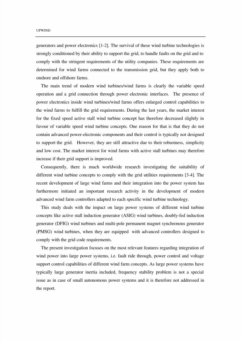
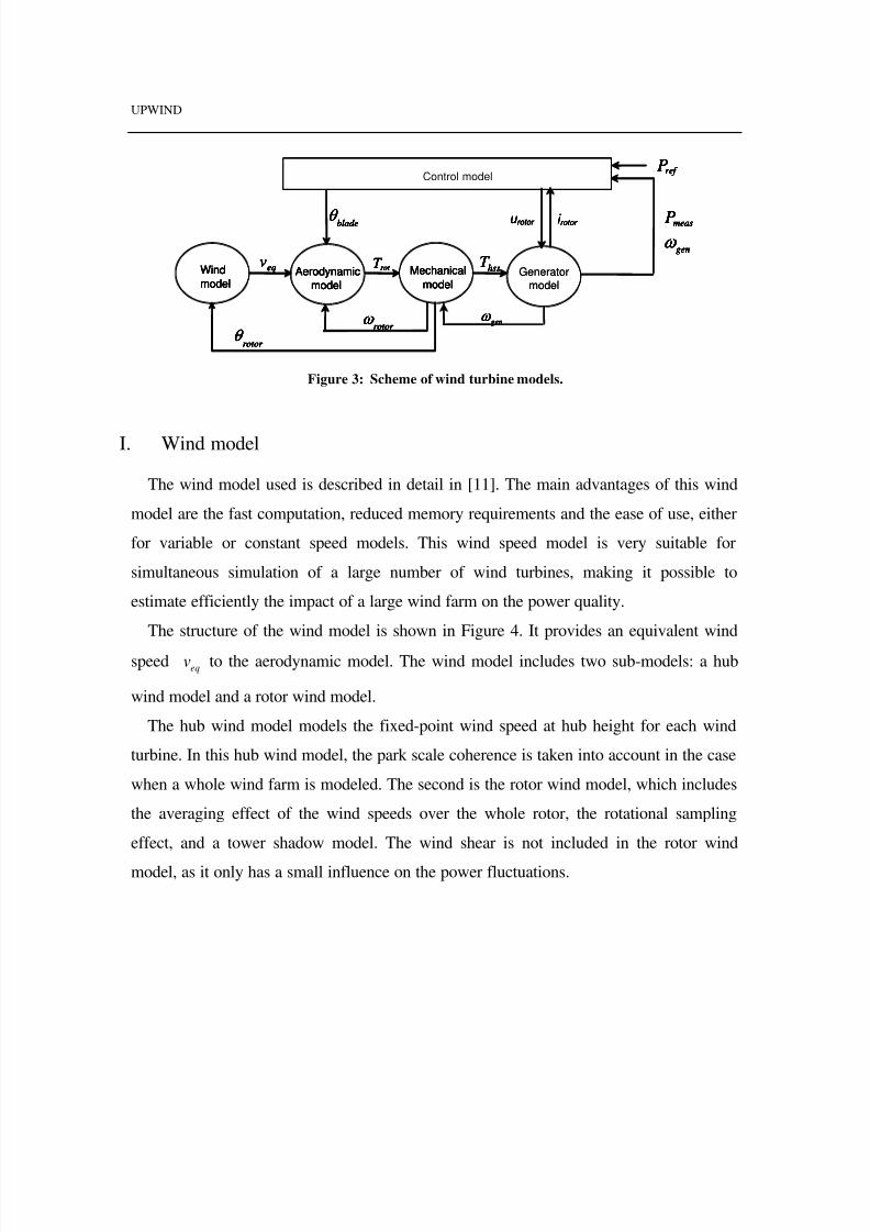
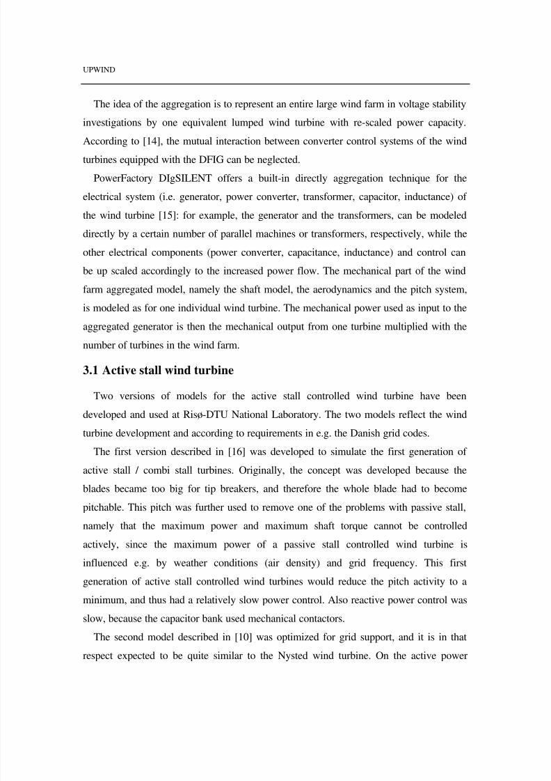
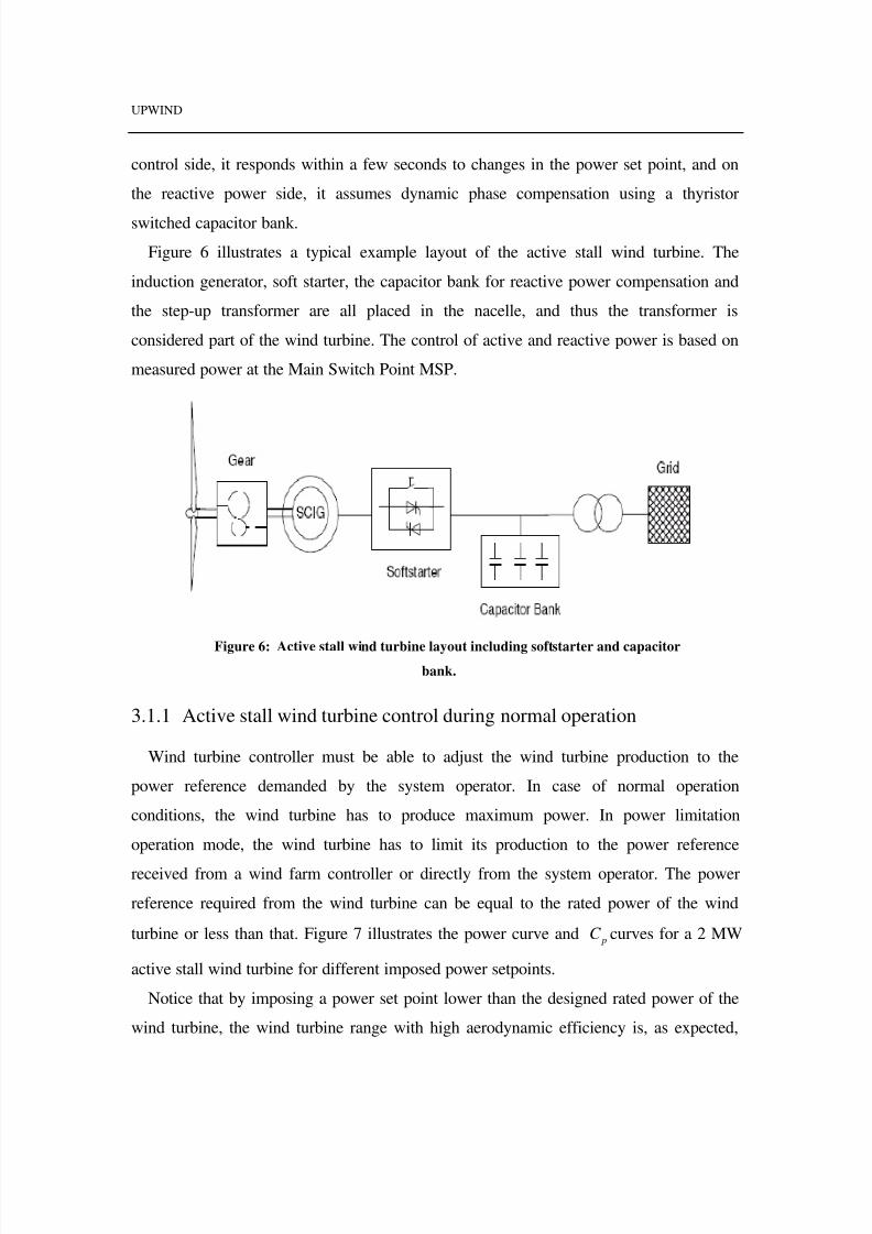
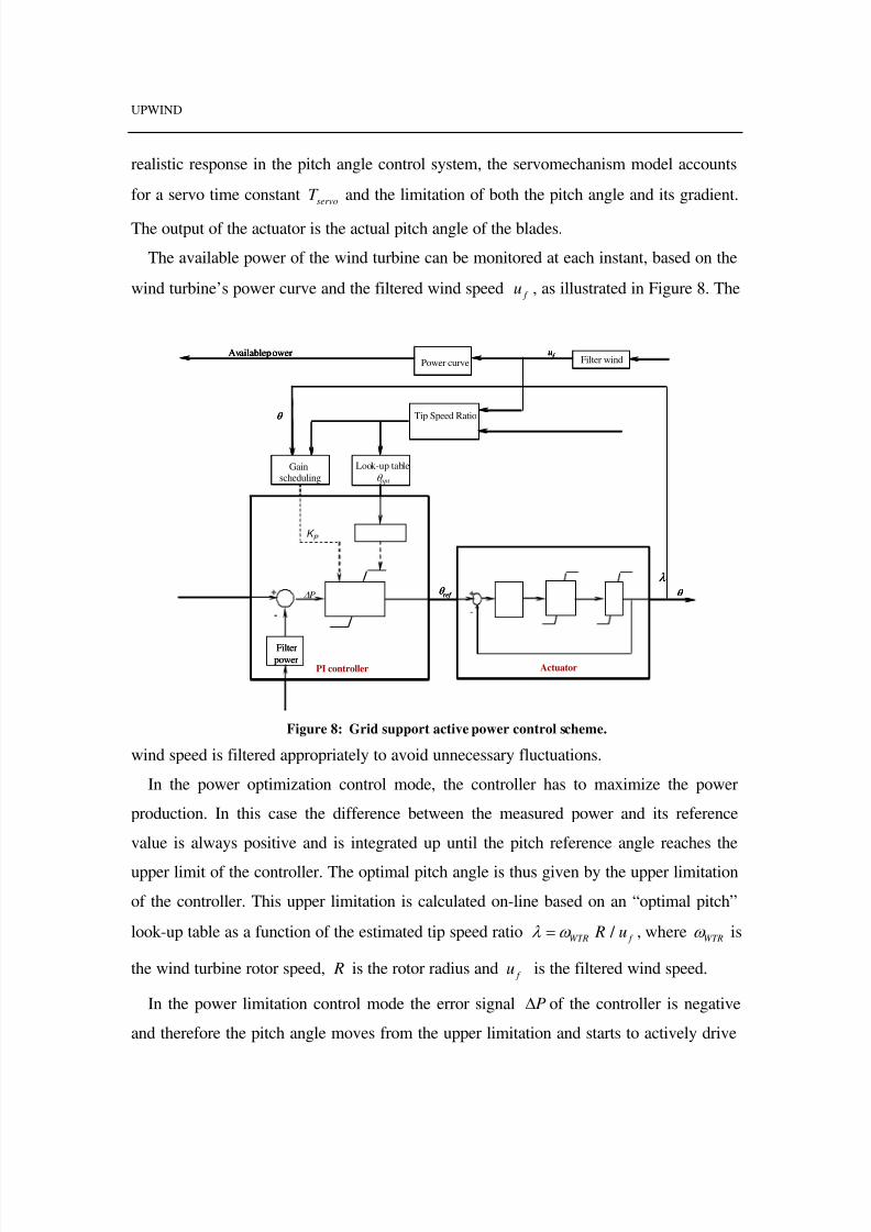
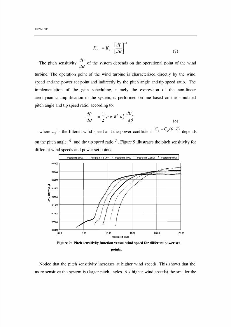
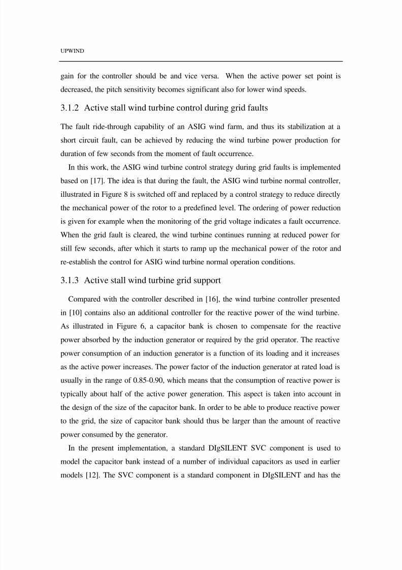
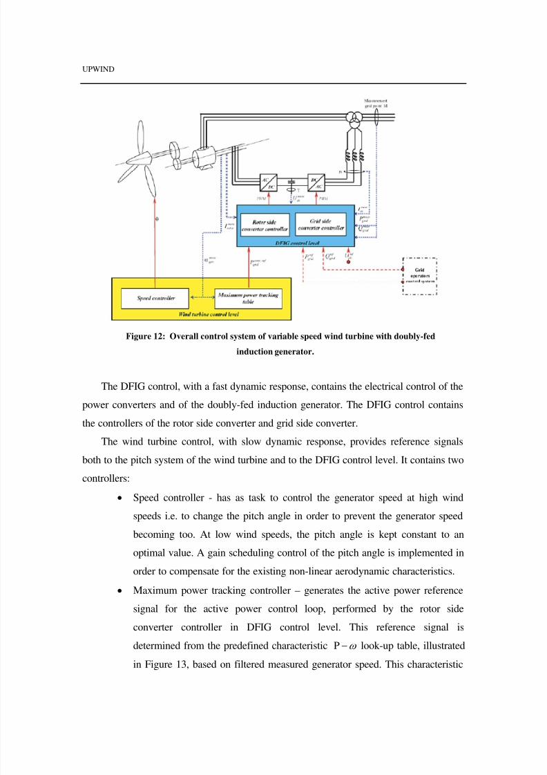
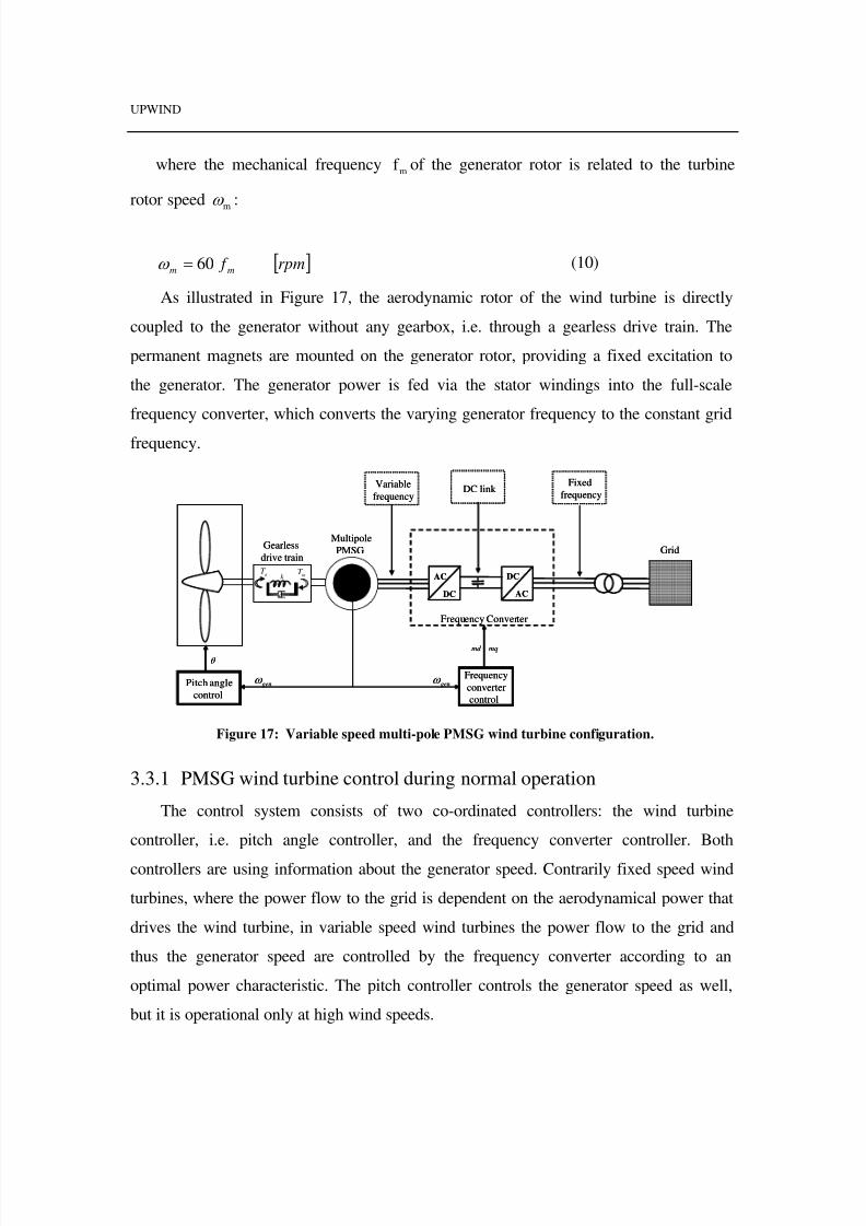
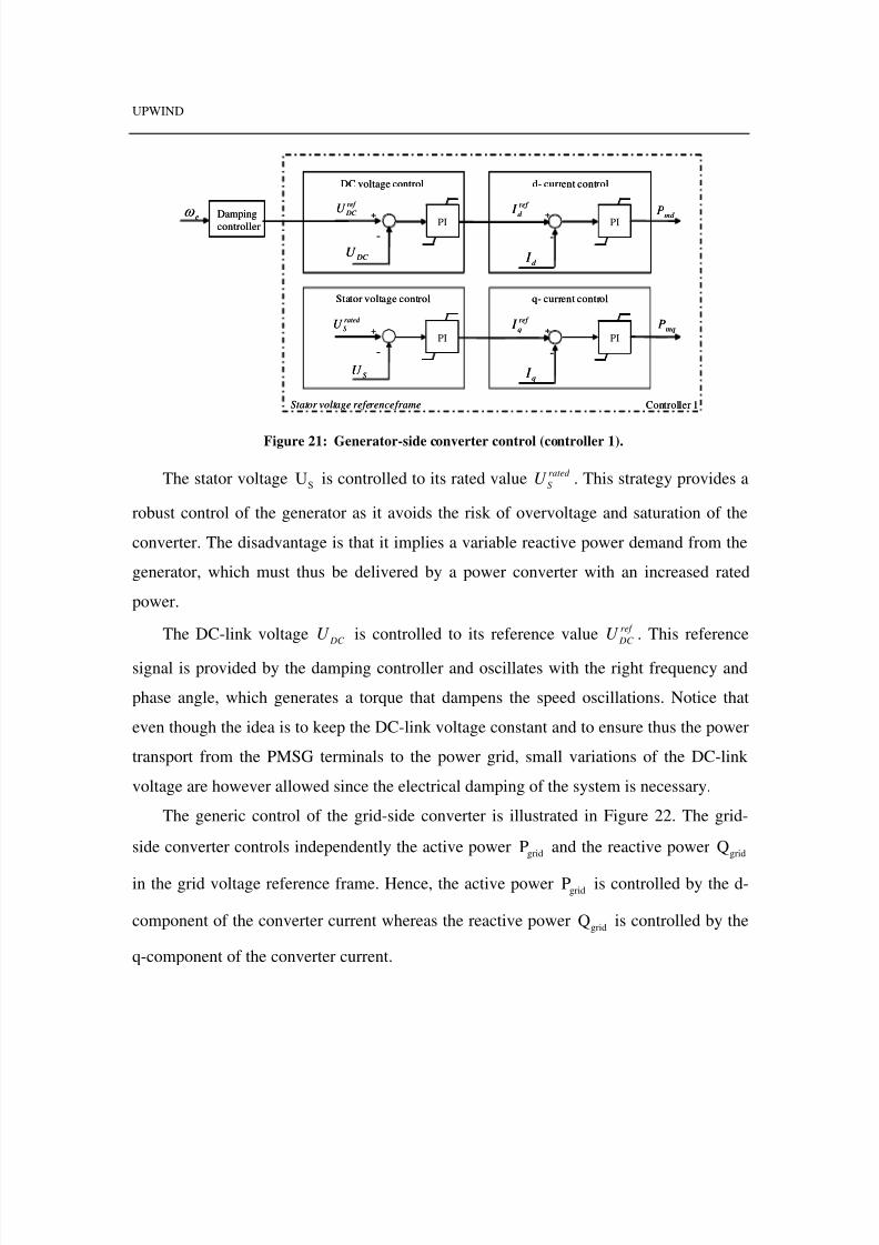
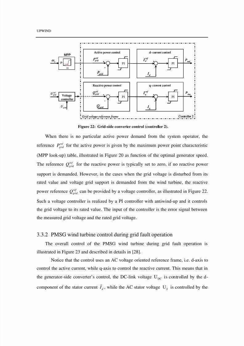
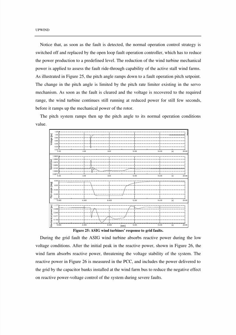
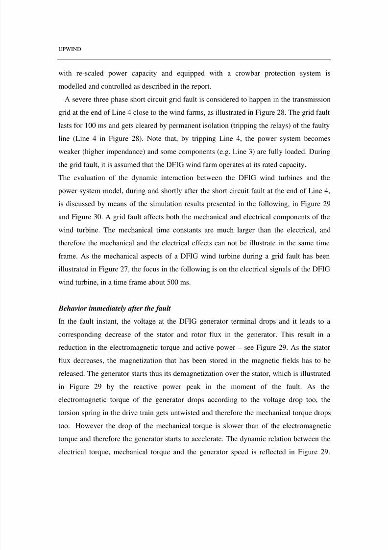
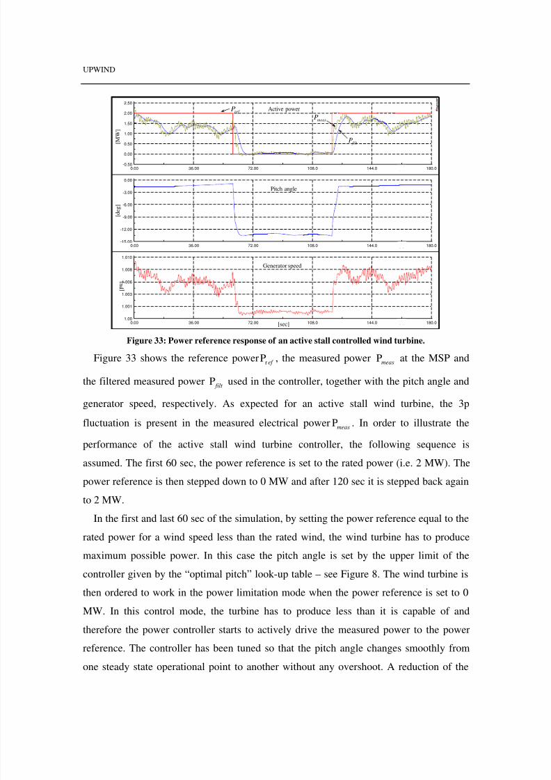
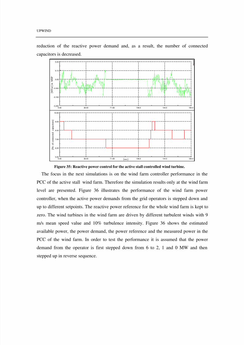
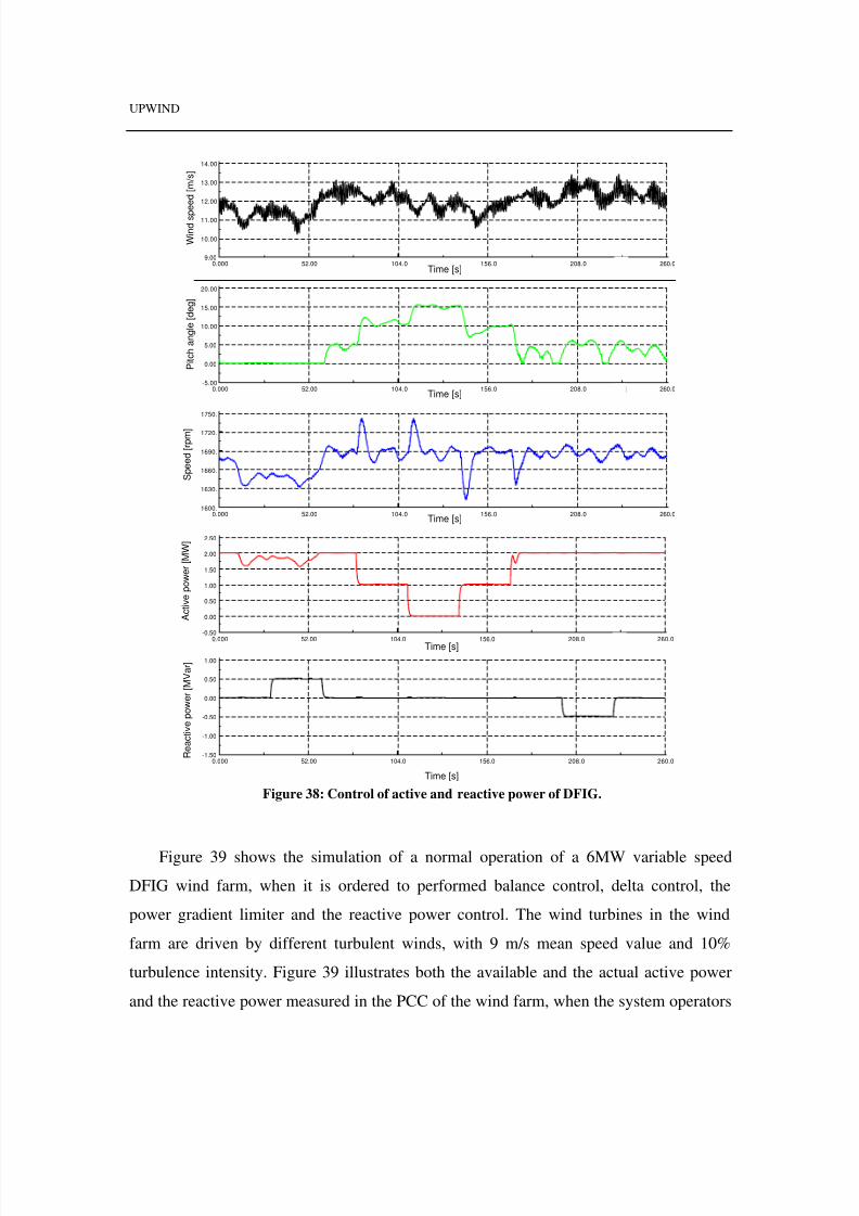
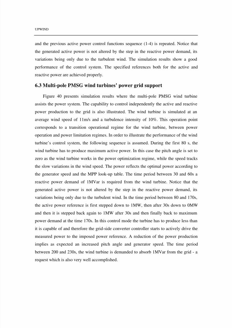
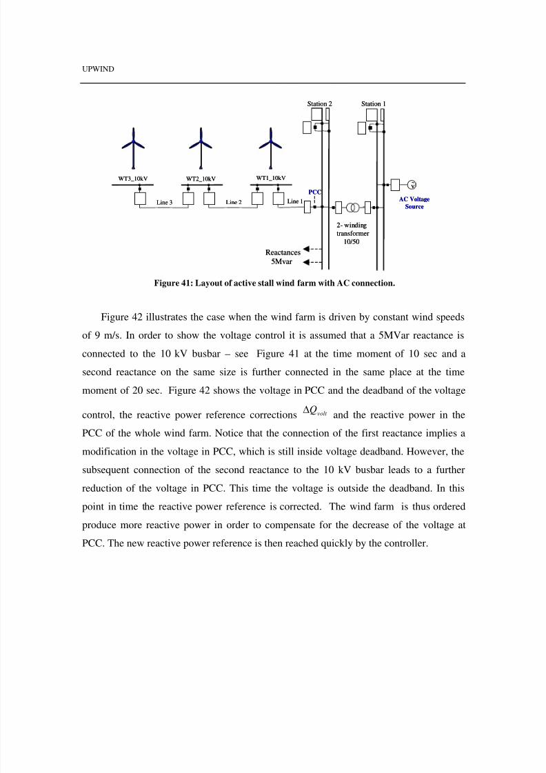
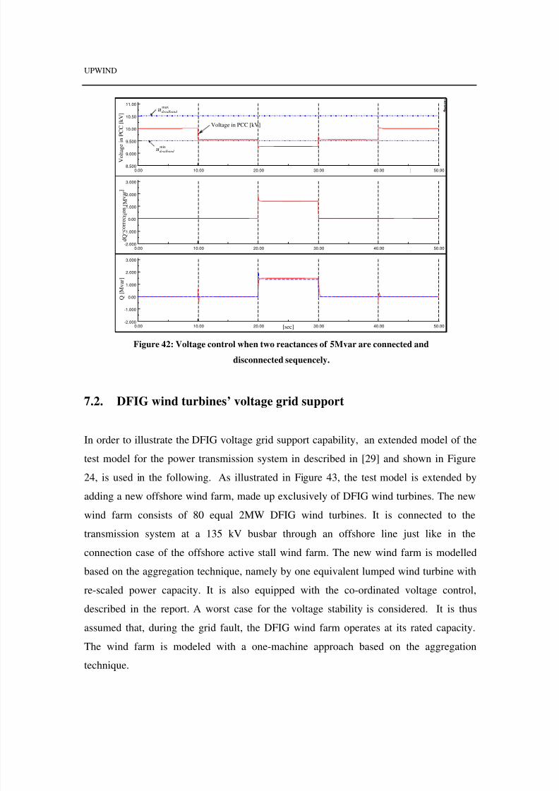
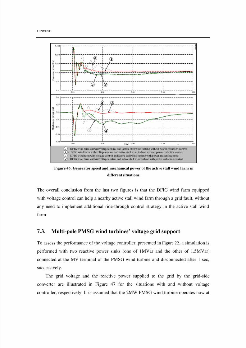
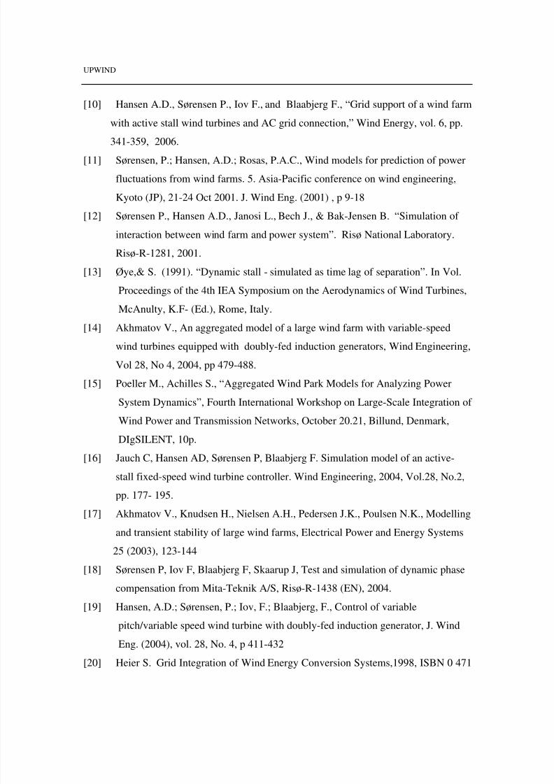
Electricity Distribution, 2005, Turin, 5p.

[26]  Hansen A.D., Jauch C., Sørensen P., Iov F., Blaabjerg F. Dynamic wind turbine

models in power system simulation tool DIgSILENT, Risø-R-1400(EN), 2003.

[27]  P. Kundur, Power System Stability and Control, Ed. McGraw-Hill, 1994.

[28]  Hansen A.D., Michalke G., Multi-pole PMSG wind turbines’ grid support

capability in uninterrupted operation during grid faults, IET Renewable Power

Generation, Vol.3,Issue 3, September 2009,p333-348.

[29]  Akhmatov, V., and Nielsen, A.H.: ‘Simulation Model of the Transmission Grid

for a Large Offshore Windfarm, Used in Education and Research at the Technical

University of Denmark’, Wind Engineering, 2006, 30, (3), pp. 255-263.


Recommended