PTD-MT-21,.269-70 00 rH FOREIGN TECHNOLOGY DIVISION THE CALCULATION OP ELECTRICAL CAPACITANCE by Yu. Ya. lossel», E. S. Kochanov, and M. G. Strunskly D D Cv WG 4 1971 :SüMD 0 Approved for public release; distribution unlimited. ..._._ »»Produced by rnrZLRN* 1 TECHNICAL INFORMATION SERVICE ipnnghmia. V» 22131 n <
Transcript
PTD-MT-21,.269-70
00
rH FOREIGN TECHNOLOGY DIVISION
THE CALCULATION OP ELECTRICAL CAPACITANCE
by
Yu. Ya. lossel», E. S. Kochanov, and M. G. Strunskly
D D Cv
WG 4 1971
:SüMD 0
Approved for public release; distribution unlimited.
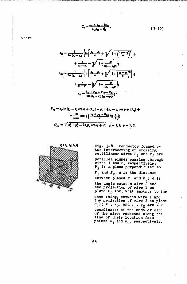
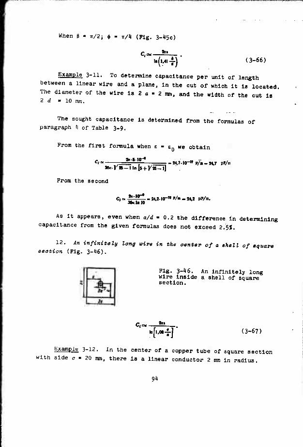
This booK is devoted to presentation of methods of calculation of ^electrical capacitance/.aiwl^contains calculation formulas, tables, and graphs necessary for determination of the capacitance of various forms of conductors.. It is intended for engineers and scientists engaged in electromagnetic calculations; it can be useful also to students and to graduate students of electrical specialties.
DD .?r..1473 UNCLASSIFIED Security Classification
UNCLASSIFIED
NCV »eiiot
Publication Calculation Electric Capacitance Electric Conductor Electromagnetism Applied Mathematics Mathematic Method
ITNCiT.A.S.STFTKn Security Clatsincatlon
FTD-MT-2'<-269-70
EDITED MACHINE TRANSLATION
THE CALCULATION OP ELECTRICAL CAPACITANCE
By: Yu. Ya. lossel1, E. S. Kochanov, and M. 0. Strunskly
This document Is a SYSTRAN machine aided translation, post-edited for technical accuracy by: W. W. Kennedy.
UR/0000-6 Q-000-000
Approved for public release; distribution unlimited.
THIS TRANSLATION IS A REMDITIOM OF THE ORICI- HAL FOREIGN TEXT WITHOUT *"* A.Hܙ1"^ <* EDITORIAL COMMENT. STATEMENTS OR THEORIES APVOCATEO OR IMFLIEO ARE THOSE OF THE SOURCE ANOPO NOT NECESSARILY REFLECT THE POSITION OR OPINION OF THE FOREIGN TECHNOLOGY DU VISION.
U. S. BOARD ON OEOORAPHIC NAMES TRANSLITERATION SYSTEM
Block Italic Transliteration Block Italic Transliteration A * A i A, * P P P > H, r B6 5»B, b C c C e S, B B» B * V, v TTr« T, t rr r » a, g y y y y u, u Al /r * D, d ♦ # • ^ F. f E • Et Ye, ye; E, e* x K X S Kh, kh M m JK M 7h, th U u « » Ts. ts 3 • 9 $ Z, t H <• V v Ch, ch H N H y I, i ill m Xtf * sh, sh 5« * ' I' I m * at * shch, sheh
A« ^* L, 1 falui/w Y, y M M Jf it M, m bbBk i HMäKN, n 9*9$ E. e Oo Oo o, o » B JD » Yu. yu n " ff • P, p « « ^ « Ya, ya
« ye initially, after vowels, and after », b; e elsewhere. When written as 19 in Russian, transliterate äs y» or ». The use of diacritical narks is preferred, but such marks may be omitted when expediency dictates.
FTD-MT-24-269-70 lv
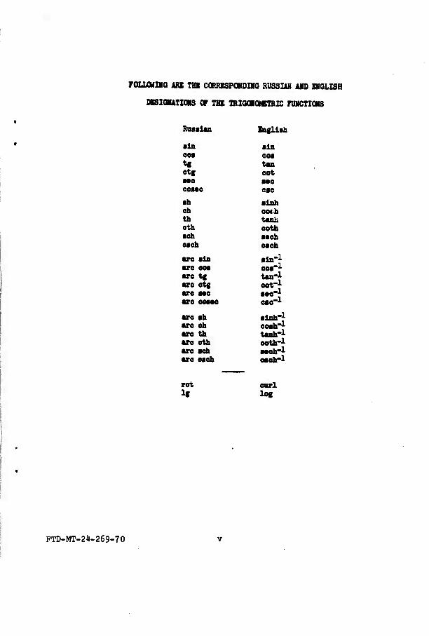
FOLUMIHO iRB TBK CCRRESPOHOIIO RUSSIAN AMD ENGLISH
DKSICBUTIONS Of THE TRIOdOeTRIC FUNCTIONS
Ruaalan Engllah
•In ain OM eoa tf tan etg eot MO aoo OM«0 eae ■h alnh eh ewh th tanh oth eoth ■eh ■•eh otch each
are ain aln-l are ooa eoa-1 are tg tan-} are etg eot-} are aae aae-} are ecaae eae"1
«re ah alnh-* are eh coah"1
are th tanh'1
are eth eoth-1 are aeh aaeh-1 are each oaeh-1
rot curl li log
PTD-MT-2J)-269-70
The book is dedioated to the presentation of methode of oalaulation of eleatrioal aapaoi- tanoe, and it oontaine a eummary of oalaulation formulas, tables, and graphe neoeeeary for the determination of the oapaaitanoe of aonduators of various form.
The book is intended for engineers and eoientiets engaged in eleotromagnetio oaloula- tione; it can be useful alev to students and to graduate students of eleatrioal specialities,
PTD-MT-24-269-70 vl
PREFACE
The necessity for the calculation of capacitance (or parameters analogous to It - electrical magnetic, and thermal conductivity) appears with the designing of various electroautomatlc and radio engineering devices, the calculation of telephonic, telegraphic, and television cables, of transmission lines and communication lines, separate elements of television, telemetering and electrometrlc apparatus, calculation of grounding electrodes, of various magnetic systems, and with the solution of a whole series of other problems which must be encountered by engineers and scientific workers of various specialties.
Because of this the problems of calculation of capacitance and parameters analogous to it have for several decades been con- sidered In physical, radio engineering, and electrical literature, and the bibliography of works dedicated to this problem published at the present time is vast.
Unfortunately, the vast majority of these works are devoted to giving an account of only individual special problems of calculation of electrical capacitance. As for the very few works in which attempts were made to give a systematic account of the problems of calculation of capacitance, they are either too antiquated,1 or
'Orllch E., Kapazität und Induktivität; 1909.
PTD-MT-24-269-70 ^11
they concern (similar to the book of R. Brüder11nk1) only conductors of a certain type.
In connection with this there has long been a need for publica- tion of a reference book on the calculation of capacity reflecting the contemporary state of this problem and containing both the fundamental methods of calculation of capacity and ready formulas, tables, and curves which refer to the most Important particular cases. This book, proposed for the readers' attention, is dedicated to the solu- tion of this problem.
In developing the plan of the book, the authors In many respects likened It to the plan of the known reference book of P. L. Kalantarov and L. A. Tseytlln on calculation of inductance, published by the State Scientific and Technical Power-Engineering Publishing House In 1955. The authors feel that this will not only be con- venient for the readers of this or other books, but also will create prerequisites for a uniform account in many respects of connected problems of calculation of capacitance and inductance in the future.
Following such a plan, the authors broke up the fundamental material of the book into two parts, in the first of which an account Is given of the methods of the calculation of capacitance, and in the second of which are given formulas, tables, graphs necessary for calculation of capacitance in various cases ■
One of the things concerning problems on calculation of electrical capacitance Is that r.trlct methods of their solution are essentially Jmieparable from methods of calculation of the electrostatic field of the system of charged bodies being considered. Along with this during the calculation of capacitance approximation methods are used, not requiring knowledge of the electrostatic field in the space surround- ing the conductors, also auxiliary methods which allow converting the system of conductors considered to a form more convenient for calculation.
'Brüderlink R., Induktivität und Kapäzrität der Starkstromfreileitungen; 195'«.
I.1TlJ-MT-2'»-?69-70 vlll
Taking Into account that the methods of calculation of electro- static fields In the majority are well Illuminated in electrical engineering and physlcomathematica1 literature,1 In the first part of the book only the less known approximation and auxiliary methods used In calculating capacitance are stated.
The account of each of the methods of calculation of capacitance is accompanied by Illustrations which should help the reader master not only the Idea of the method, but also the characteristics of Its application to the solution of concrete practical problems.
In the second, reference, part of the book, the authors strove as fully as possible to present the data necessary for calculation of capacitance of conductors of the most typical form, without facing the problem of summarizing all results published up to the present time (within the confines of one book this would be, apparently, generally Impossible). The application of reference data Is Illustrated by Illustrations of a calculation reduced to numerical results.
In conclusion the authors express sincere gratitude to the reviewer. Doctor of Technical Sciences L. A. Tseytlln and the scientific editor. Candidate of Technical Sciences R. A. Pavlovskly, the participation of whom In the consideration and preparation of the present book went far beyond the scope of their formal responsibilities.
The authors hope that this book will be useful to a wide circle of engineers and scientific workers engaged in electromagnetic calculations.
Comment!; and remarks on the content of the book should be sent to: Leningrad, U^SR, Leningrad, D-'ll, Marsovo pole, d. 1, Lenlnpradskoye otdelenlye izdatel'stva "Energlya." Authors
'See, for example, V. Smayt, Elektrostatika 1 elektrodinamika (Electrostatics and Electrodynamics), IL, 195^, N, N. Mirolyubov et al., Metody rascheta elektrostatichesklkh poley (Methods of Calculation of Electrostatic Fields), Vysshaya shkola, 1963.
PTD-MT-21-269-70 lx
INTRODUCTION
V-l. Basic Definitions
Between charges and potentials In any system of conductors that create an electrostatic field, a one-to-one linear relation exists, for the expression of which the concept of electrical capacitance or simply capacitance is introduced.1
c Depending on the type of system of conductors considered, the
apacltance of a solitary conductor, the capacitance between two
conductors and the capacitance in a system of many conductors are distinguished.
The aapaoitanoe of a solitary oonduotor is a scalar quantity characterizing the ability of the conductor to accumulate an
electrical charge and is equal to the ratio of the charge of the
conductor to its potential on the assumption that all other loaded
conductors are an infinite distance away.
If the charge of a solitary conductor is designated Q, and its potential V, then in accordance with the given definition, the
Here and subsequently, if nothing is said to the contrary, it is assumed that the specific Inductive capacitance of the medium surround- Inp; the conductors does not depend on electrostatic field strength, all the conductors being considered are in a finite region of space, and that the potential at an Infinitely distant point Is equal to zero.
PTD-MT-24-269-70
capacitance of this conductor will be expressed by the formula
c,--5-. (V-l)
The aapaaitanoe between two oonduotore Is a scalar quantity equal to the absolute value of the ratio of the electrical charge of one of the conductors to the difference In their potentials on condition that these conductors have charges Identical in amount, but opposite In sign and that all other loaded conductors are Infinitely far away.
If the charges of the conductors are equal to ±Q, and their potentials have quantity V1 and V2, then In accordance with the Klven definition, the capacitance between these conductors can be expressed by the formula
Hi^l- (V-2)
An arrangement of two conductors separated by a dielectric
(plates) Intended for utilization of capacitance between them Is
called a capacitor; therefore, the capacitance between two conductors
Is sometimes called also oapaoitor aapaaitanoe.
The generalization of Introduced concepts In the case of a
system with a random finite number of conductors Is a concept about
Intrinsic and mutual partial capacitances.
The conductor's intrinaio partial oapaoitanae that enters the system of many bodies Is a scalar quantity equal to the ratio of
the charge of this conductor to its potential on the assumption that
all the conductors of the system (Including the one being considered)
have identical potential.
Mutual partial oapaoitanae between two conductors that enter the system of many bodies is a scalar quantity equal to the ratio
of the charge of one of the conductors being considered to the
I''TD-MT-2'»-?69-70 xl
potential of another on the assumption that all conductors, except
the latter, have potential equal to zero.
In accordance with the Introduced definitions the relation
between charges and potentials In a system of n conductors Is expressed
where C^ la the mutual partial capacitance between the t-th and fc-th electrodes In an electroneutral system (C!. - C!.).
The quantities Ci^ can be defined In the same way as C.., on the assumption that all conductors, except one, have about the same (but not necessarily equal to zero) potential. In general the quantities C^fe are not equal to the quantities C.., but can be expressed through them.
Equations (V-3) or (V-'l) can be converted, grouping on their right sides terms having a factor value V^. in this case the system of equations connecting charges and potentials of conductors takes the form:
The quantities entering these equations B.fe are called ootffi- oiente of eleotroatatio induotion (intrinsic when i - fe and mutual when i i* k), and, as can be shown,
?»><•. l'*-t«»<o.
Another form of recording of relationships (V-5) is:
Vt - IMQI + iußt+ ... +*MQm
(V-6) f« - «mfli + •<n9i+ .. • + «mQ*
The quantities oife entering (V-6) are called potential aoeffi- oiente (intrinsic when i - fe and mutual when i ft k). a.. > 0. aik > 0' »tfe * %€ < «fefe-
The systems of equations (v-3)-(V-6) are various forms of the expression of one and the same interrelationship between charges and
PTD-MT-2'»-269-70
potentials of conductors In a system of many bodies. Therefore, the coefficients which enter the equations are also Interconnected.
Thus
c»» - %» + ft» + . • ■ fc» + • • • f fc*
When a system consists of one conductor (« ■ 1), the concept of intrinsic partial capacitance coincides with the concept of the
capacitance of a solitary conductor: CQ ■ C^.
When a system consists of two conductors (n ■ 2) and Is electro- neutral, the concept of mutual partial capacitance coincides with the concept of the capacitance between two conductors: C ■ C^g. In this
case the following relatlonshlpfj are also valid:
c - CMCH+Safie + ^w. Ca + C«
c- hi + b+Vit
I
As follows from the definitions given above, the values of the
capacitance of solitary conductors, of the capacitance between two
conductors and of the capacitances in a system of many conductors
are substantially positive and are defined only by the geometric
parameters of conductors and by the specific inductive capacitance
of the environment. From these determinations it is evident also
that the quantities CQ, C, C^, Cfefe, 6ifeJ 6fefe and ^fe are quantities
of the same dimension and can be united under the name of capacitlve
coefficients (unlike potential coefficients having reverse dimension),
V-2. General Features of Capacitance and Classification of Conductors
A. Kormulated below are some general positions expressinsr the
dependonce of the capacitance of conductors upon their geometric
FTD-MT-2t-269-70 xiv
parameters and the specific Inductive capacitance of the environment.
1. At a constant value of apeoifio inductive octpaoitanoe the relationships of the capacitances in two geometrically similar systems of conductors are equal to the relationship of the characteristic sizes of these systems:
Cj «■ c1 V 4» a1
^r —5rs ^r--ir: ^... • (v-7)
where a and a are the characteristic sizes of systems I and II.
When the form of conductors is such that the electrostatic fields being Induced by them can be considered plane-parallel,1 the capacitances (per unit of length of conductors) in geometrically similar electroneutral systems of two or more bodies2 equal between themselves:
cj-cr, cjfc.-dti. (v-8)
where C"-—, CS.! —-A-, m« i, n, /■ is the length of the conductors
(in the direction of their axis).
2. At identical geometric parametere of two eyeteme of con- ductors in uniform media with various specific Inductive capacitances, the relationships of similar quantities characterizing capacitance in these systems are equal to the ratio of specific inductive capacitances:
'Such systems of conductors will subsequently be called plane- parallel.
2The concept of the capacitance of a solitary conductor in this Instance makes no sense physically.
PTD-MT-24-269-70 xv
T TT where eJ and e are the specific Inductive capacitances of the
media in systems I and II.'
This feature Is valid also for the case of heterogeneous media
on condition that the spatial distributions of specific inductive
capacitance In systems I and II are similar. Together with those
given can be shown a number of features of capacitance which are
valid only for Individual types of systems united by any general
criteria. One of such criteria is the presence of a boundary of
division of two uniform media with various specific inductive
capacitances.
Let the conductors being considered be located in a medium with
specific Inductive capacitance c^ near the boundary of division of media with specific Inductive capacitances c-^ and Eg. If e^ « Cg. then the boundary of division of media can be considered equipotential.
I.e., It can be considered a surface of an ideal conductor. If
e, >> e_, then the boundary of division can be considered impenetrable
for power lines of an electrostatic field and therefore it can be
considered the surface of a certain conditional medium with zero
specific Inductive capacitance. Such a boundary will be subsequently
called impenetrable.
For the capacitance of conductors near an infinitely extended
flat Ideally conducting or impenetrable surface, the following basic
relationships are valid.
1. The capacitance between any solitary conductor and an
Infinite Ideally conducting surface (Pig. V-la) is equal to the
doubled value of the capacitance between this conductor and its
mirror reflection relative to the plane (Pig. V-lb).
2. The capacitance of any solitary conductor 1 near an Infinitely
extended flat Impenetrable boundary (Pig. V-2aX is equal to the half
of the capacitance of the solitary conductor formed by the union of
'Analogous equations are valid even for all remaining capacltive coefficients while for potential coefficients the opposite relation- ships are fulfilled.
i."ri-MT-?i«-?f>«-7n
Pig. V-l, Pig. V-2.
conductor 1 with its mirror reflection 2 relative to the plane
(Fig. V-2b).
B. Subsequently we will subdivide conductors according to
their geometric form into wires, flat platee, open and oloeed ehelle. The latter in an electrostatic sense is equivalent to the solid
conductors of the same form, with the exception of those cases when
other charged conductors are inside the shells. In considering wires
we will assume that their sections are constant in length and the
linear dimensions of the section are considerably less than the
length of wire and the distances to other conductors. In considering
flat plates and shells we will consider that their thickness at every
point of surface is constant and in all cases when nothing is said
to the contrary is infinitesimal.
With the assumptions made the following extremum properties of
capacitance are valid.
1. Of all solitary straight wires of assigned length and area
of transverse section, the one with the least capacitance Is the
wire of circular section.
FTD-MT-24-269-70 xvli
2. Of all flat plates of assigned area the one with least
capacitance Is the circular disc.
3. Of all triangular flat plates of assigned area, the one
with least capacitance is a plate In the form of an equilateral
triangle.
i). Of all rectangular flat plates of assigned area, the one
having least capacitance is the square plate.
5. Of all bodies of an assigned volume the one having the
least capacitance is the sphere.
6. Of all right cylinders of assigned altitude and area of
transverse section, the one having the least capacitance is the
right circular cylinder.
7. Of all systems in the form of two circular Infinitely long
cylinders with parallel axes, one of which envelopes the other, the
one with least capacity per unit of length is the system In the form
of coaxial cylinders.
Very characteristic features are possessed also by the capaci-
tance of the system shown in Pig. V-3. Let curve OAO'A' represent the section of an infinitely long cylinder, symmetrical with respect
to line 00'. Considering the surface of a cylinder an impenetrable boundary of a medium with specific inductive capacitance e, filling
the Inside of the cylinder, we assume that OA' and O'A are sections of infinitely long conductors 1 and 2, and points A and A' are symmetric relative to plane 00 '.
m.)-MT-2l)-?69-70 xviii
In the conditions shown the capacitance between conductors 1 and i ''per unit of length) Is numerically equal to c.1
An analogous feature can be formulated also for a system which
differs from the one shown In Pig. V-3 only by the fact that it con-
tains not two, but four divided Inflnlteslmally thin gaps of conductor
1, 2, 3 and 4, the sections of which coincide with lines OA, AO', O'A' and A'O, respectively (Pig. V-lt). For this system the mutual partial capacitance between dny two crosswise lying conductors per
unit of length (C13 l or C^ j) Is equal to e in 2, whatever the
form and dimensions of the section of the cylinder.2
Pig. V-l«.
V-3. Units of Measurement of Capacitance
The unit of measurement of capacitance In the system SI [Inter- national System] Is the farad (P). Furthermore, fractional units are used: microfarad (uP) and picofarad (mlcromlcrofarad) (pP):
1 pP-HT» P,
I pP-lO"1» P.
To find capacitance In farads It is necessary to multiply Its
value In another system of units by the appropriate conversion factor.
The feature shown was noted for the first time for a particular case in the work of Lees C. H., Proc. Manch. Lit. and Phil. Soc. 1899, 1-3; in general form it was formulated by P. Bowman (Bowman, F. Proc. of the Lond. Math. Soc. 1935, ser 2, V. 39, p. 3, 205-213), anJ then was again considered by A. V. Netushil f"Elektrichestvo" 1951. No. 3).
'See, for example, Lampard D. G., Proc. IEE, 1957, C. 10'», N 6, 271-280.
PTD-MT-2')-269-70 xix
The conversion factors of values of capacitance from other systems
of units to the SI system have the following values:
where o is the number value of the velocity of the propagation of Q
electromagnetic waves in free space (in m/s), equal to 2.997925*10 .
V-Jt. Analogy Between Capacitance and Other Physical Quantities
Because of the mathematical analogy of potential fields of different physical nature, for each of them It is possible to show the analog of electrical capacitance. Thus, for instance, for stationary electrical, magnetic, and thermal fields such analogs are electrical, magnetic, and thermal conductivities, respectively. At assigned geometric parameters of the system of bodies, the value- analogs of electrical capacitance are proportional to it, and the coefficients of proportionality are the relationships of the appro- priate physical parameters of a medium to specific inductive capaci- tance. Specifically, for two bodies
(V-10)
(V-ll)
(V-12)
0 = -i-C; 1
c.= fc:
or= ■fc.
PTD-MT-2')-269-70 xx
where G is the electrical conductivity between the bodies being considered In a uniform medium with specific electrical conductivity Y; (JM is magnetic conductivity between bodies in a uniform medium with permeability u; G is the thermal conductivity between bodies in a uniform medium with thermal conductivity coefficient X; C is the capacitance between bodies in a uniform medium with specific inductive capacitance e.
The same relationships connect partial conductivities and partial capacitances in the system of many bodies.
Apart from the one Indicated there is also an approximate analogy between electrical capacitance and certain parameters of high-frequency electromagnetic systems.1 At assigned geometric layout of the system of conductors, at high frequency especially, the following approximate relationships are valid:
r«£Ü; (V-13) c
where W is the wave resistance of a system of two conductors in a uniform medium with specific inductive capacitance E and permeability p, C is the capacitance between these conductors;
t/«-^. (V-llt) w
where L^ is the Inductance per unit of length of a two-wire line in a uniform medium with permeability w; C^ is the capacitance between these conductors (per unit of their length) in a uniform medium with specific inductive capacitance e.
For rectilinear wires the following relationships can also be shown:
/-»* tt •i''»«»*. (V-15)
In this case frequency is assumed to be so high that the lines of the magnetic field can be considered outside the sections of conductors.
PTD-MT-24-269-70 xxl
where l.y Is the Inductance of a wire l^ long In a homogeneous medium
with permeability p; OLL IS the Intrinsic potential coefficient of a
wire In a homogeneous medium with specific Inductive capacitance e,
calculated by the method of mean potentials (see S 1-2);
«rt a lHV» COS «fvtoji, ( V-16 )
where W.. Is the mutual Inductance of two wires li and l^ long at
an angle iti.u to each other In a homogeneous medium with permeability
u; ct.. is the mutual potential coefficient of the same wires In a
homofreneous medium with specific inductive capacitance c, calculated
by the method of mean potentials.
The examined analogy makes the calculation of capacitance
equivalent to the calculation of a number of other physical parameters,
specifically:
a) magnetic conductivity of various magnetic circuits;
b) resistance of spreading out of electrodes connecting
electrical circuits with conducting medium (for example, grounds);
c) wave resistance of wave guides, strip lines, antennas, and
other transmitting and radiating systems;
d) thermal conductivity between various heated bodies.
V-5. Means of Calculation of Capacitance
Formulas (V-l)-(V-6) cannot be directly used for calculation of
capacitance (or quantities connected with it) because usually only
geometric parameters of the system of conductors and the specific
inductive capacitance of the surrounding medium are known. Therefore,
to determine capacitance it is necessary either to design charges
of conductors, having been assigned by their potentials, or, on the
contrary, to find the potentials of conductors, having been assigned
by the quantity of charges.
PTD-MT-2't-269-70 xxl1
Both these problems can be strictly solved on the basis of calculation of the electrostatic field of the system of conductors being considered. Really, knowing the distribution of electrostatic field potential (M) In the space surrounding the conductors, It Is possible to find the charges of each of them with the aid of the relationship:
>,,-|. *r*' (v-i7)
where Qi Is the charge of the i-th conductor; S. is the surface of the t-th conductor; n Is the external normal to the surface of the conductor.
When the electrostatic field cannot be calculated, special methods of calculating capacitance are used which are based either on directly establishing the connection of the charge of the conductor with the potential of Its surface (methods of direct determination of capacitance), or upon simplification of problems of calculation of electrostatic field (auxiliary methods).
Formulation of problems of calculation of capacitance depends upon the selection of Initial quantities (charges or potentials), which. In turn, is determined by the form of the system of conductors considered.
In calculating the capacitance of a conductor. Its potential or charge can be assigned at random. If it Is supposed that potential is equal to one, then the charge of a solitary conductor will be numerically equal to its capacitance. In calculating the capacitance between conductors, as a rule. It Is possible to define only their charges, and the condition Q2 « -Q1 must be observed.
The potentials of both conductors In general cannot be selected at random since they are connected by the relationship
-£—■£. (V-18)
raJ-MT-24-269-70 xxlll
following from (V-3) when n ■ 2, ^ - -Q2.
The assignment of potentials as initial quantities is possible
only in certain special cases, for example, the following,
1. The system of two conductors is symmetrical relative to a
certain plane. In this case C,, >■ C22, and at Q, - -flj ^T " ~V2 " A' where A is a random quantity.
2. The dimensions of one of the conductors (for example, the
first) are Incommensurably great in comparison with the dimensions
of the other. Here C^ >> C22, C22^C11 S ^ 1•e•» ^i * 0> V2 m A»
where /I Is a random quantity.
With the calculation of partial capacitances in a system.
Initial quantities can be In general only their potentials.
Thus, with calculation of intrinsic partial capacitance, the
potentials of all conductors of the system must be taken equal to one
and the same random constant, and in calculating the mutual partial
capacitance between the i-th and fe-th conductor, the potential of
one of them can be selected at random, and the potentials of all the
remaining conductors must be taken equal to zero.
As already noted in the preface, methods of calculation of
electrostatic fields are covered in sufficient detail In literature;
therefore. In the last two chapters of this book, only special
mothod.-. of calculating capacitance are considered.
•'T!j-M,r-2')-;'69-70 xxiv
PART ONE
SPECIAL METHODS OP CALCULATING CAPACITANCE
KTO-MT-P'l-^Cy-TO
CHAPTER 1
METHODS OP DIRECT DETERMINATION OP CAPACITANCE
1-1. General Remarks
Methods of direct determination of capacitance are applicable when conductors are in homogeneous media. These methods are based on replacement of each of the conductors considered with a dielectric body having the same form as the conductor, and the same specific inductive capacitance as the surrounding medium. Instead of an unknown true (equilibrium) distribution of charge over the surface of the conductor, a certain fictitious distribution of charge over the surface of the body o(S) or in its volume p(w) is assigned. Methods of assignment of functions o(S) or p(v) depend on the features of concrete methods of direct determination of capacitance; however, In any selected form of these functions, the value of the total charge of the body is found from the formulas
Q^-f.CS)« (1-1)
or
Qi-JpOOA, (1-2)
and the potential at the random point (Pu) of the surface of the body from the formulan
vW~-rTV,\~ySLr><lS (1-3) f.t),-LVr «ffl as
FTD-MT-21-269-70
n^-^yu^r*. d.i.)
where P. Is a point either on the surface of the t-th body (1-3),
or In Its volume (l-b); '(Pt; P.) Is the distance between points PL and P.; « Is the number of conductors In the system.
For a plane-parallel system of conductors, Instead of (1-3)
and (1-k) one ought to use the formulas:
or y(P*)--j-<y>f-<sn« ..' ..«. (I-1*')
where L. Is the contour of the section of the i-th body; T(L) IS the linear density of a charge on the contour of the section of the t-th body; a(5) is the surface density of the charge in a section of the i-th body; Py is a point of the contour of the section of the fe-th body; P. is a point either on the contour of the section of the i-th body (1-3') or inside its section (1-1'), '(^fe, p^) i8 the distance between points p. and P., lying in the section.
In general the surface of the body considered is not equipoten- tial, whereas the surface of any conductor is equipotentlal. To get rid of this discrepancy of the whole surface of the body, a certain constant potential V. Is conditionally added, the value of which is determined by this or that method according to the distribution of the potential found from (1-3) or (l-i0.
Disposing Q. and V. for each of the conductors of the system (t ■ 1, 2, ..., n), the capacitances of this system can be found approximately using formulas (V-l)-(V-'t).
KTD-MT-2't-?69-70
1-2. The Method of Mean Potentials
The method of mean potentials is based on assignment of a
fictional distribution of charge over the surface of or in the volume
of bodies replacing conductors. In this case the surface of each of
the bodies is ascribed a constant potential equal to the arithmetic
mean of values of potential in all points of the surface of the body
(v = vcp). This quantity (Vcp) is called the mean potential of the surface or the mean potential of the conductor.
When the method is used to determine 7, the law of fictional
distribution of charge has comparatively little effect on accuracy
of determination of capacitance (Inasmuch as capacitance is an
integral characteristic of electrostatic field) and is usually
selected only from conditions of simplicity of calculations. The
most widespread assumption is that the charge Is uniformly distributed
over the surface of the body. A method of calculation of capacitance
based on this was proposed by 0. Howe [1-1] and bears his name.
Other methods besides this were proposed for assigning the law
of surface distribution of charge, using the method of mean potentials.
Thus, in [1-2] it is proposed to select this law in the form
-m' where S is the surface of the conductor; >1 is a random quantity;
r is the distance between two points of the surface S, one of which is a running point and the other of which is a fixed point.
Formula (1-5) in a number of cases gives a better approximation
than in the Howe method to equilibrium distribution of charge;
however, the calculation formulas obtained are usually more complex.
Bolow we nhall limit ourselves mainly to consideration of the
llowo method, which is the most widespread method of direct determina-
tion of capacitance.
For a solitary conductor mean potential can be determined according to the formula
v^vwäS-^äS'jJL. (1.6)
where S Is the surface of the conductor considered (and also the area of this surface); 7(p) Is the potential at point p of surface S, determined by formula (1-3); Q Is the total charge of the conductor; r is the distance between the points of the surface of the conductor.
Calculation of mean potential by formula (1-6) in a number of
cases can be simplified, having broken the surface of the conductor
into Individual sections and consecutively calculating the mean
potential of each of them as a solitary body. Into these cases the
mean potential of the whole conductor Is determined by the formula
i
^».•|t. (1-7)
where S. Is the area of the surface of the fe-th section; S Is the total area of the surface of the conductor; V y Is the mean potential of the fe-th section; n Is the number of sections Into which the surface of the conductor is divided.
For wire the ratio Sy/S in this form can be replaced by the ratio Zfc/Jj where ty ±B the length of the fe-th segment of wire, and
I Is the total length of wire.
From formulas (1-6) and (V-l) it follows that the capacitance of
a nolJtary conductor calculated by the Howe method Is determined by
the expression
C^^Udsr^y. (1_8)
vnth calculation of the capacitance between two conductora, the mean potential of each of them Is found from the formulas
v.p.-^rlY,f-f-2—M-s-^s
'cp« '
where 5, and S» are the surfaces of each of the conductors considered (and also the areas of these surfaces); r,, and r-p are the distances between two points of one and the same conductor (of the first and second, respectively); r-,- = *•„ Is the distance between two points, one of which lies on the surface of the first conductor and the second of which lies on the surface of the second; Q is the total charge of one conductor.
As in the previous case, calculation of mean potentials of conductors can be simplified, having divided the surfaces of each or of one of them Into separate sections or segments (in the case of a wire) and having used formulas (1-7).
In calculation of the difference of mean potentials between two conductors, use can also be made of the principle of mutuality of mean potentials, which consists of the following.
The mean potential of conductor A Induced by charge Q, is evenly distributed on conductor B, and Is equal in absolute value to the mean potential of conductor B induced by a charge - Q, uniformly distributed on conductor A.
lJ:;e of formulas (1-9), taking the mutuality principle into account, lead:; to the expression
' cpl r cpt ' I-BI :—
From formulas (1-10) and (V-2) it follows that the capacitance tetween two conductors calculated by the Howe method Is determined by
the expression
Anl-i-
(i-ii)
When a system of two conductors is plane-parallel Instead of (1-11) the next formula, analogous to it, for capacitance per unit of length of conductors should be used:
+ i]['t'J[",i't)"' . (1-12)
where L, and L2 are the contours of the sections of conduotcrs considered (and also the perimeters of these sections); r^, r12, and r22 are the distances between the corresponding points on the contours of the sections (see designations to formula (1-9)).
In calculation of partial capacitances In a system of many bodies, direct use of the method of mean potentials Is difficult since it usually leads to bulky calculations. Therefore, In the given cases the method of mean potentials is used, as a rule, to calculate potential coefficients with subsequent conversion to partial capaci- tances on the basis of the relationships given In V-l.
Calculation of mean potentials in a system of n conductors is
based on utilization of the formula
..-zb-r v.^m*-. (i-i3) HPi*)-
where V . Is the mean potential of the i-th conductor; St. is the opt * surface of the fe-th conductor (fe ■ 1, 2, ..., n) and also the area of this surface; q. Is the full charge of the fe-th conductor; r^ i» the distance between two points on the surface of different conductors (fe ^ O or one conductor (fe » i). In this case between the quantities of the mean potentials of any two conductors (4 and fl) the relation- ship Is satisfied1
^-|i. (1-14)
where 7, is the mean potential of the conductor ki created by j4cp
charge ög, uniformly distributed on conductor B; V. Is the mean potential of conductor fl created by charge Qfi uniformly distributed on conductor A ,
In determination of partial capacitances the charges of all the conductors of the system must be taken as different from zero, and calculations made using formula (1-13), even allowing for relation- ship (1-14), become very lengthy. Upon finding potential coeffi- cients (when only one of the conductors must be considered charged) formula (1-13) is strongly simplified and coincides in form with (1-6). This leads to the following expressions for intrinsic and mutual potential coefficients calculated according to the Howe method:
jff-f' (1-15)
'*''*£& j^jf*' (1-16)
For a plane-parallel system of n conductors, analogous formulas take the form:
'When \Q \ = \QB\, this formula expresses the principle of mutuality of mean potentials formulated above.
•'""^"'J'"^ (1-17)
^-Tsk^'I'-i* (i-i8)
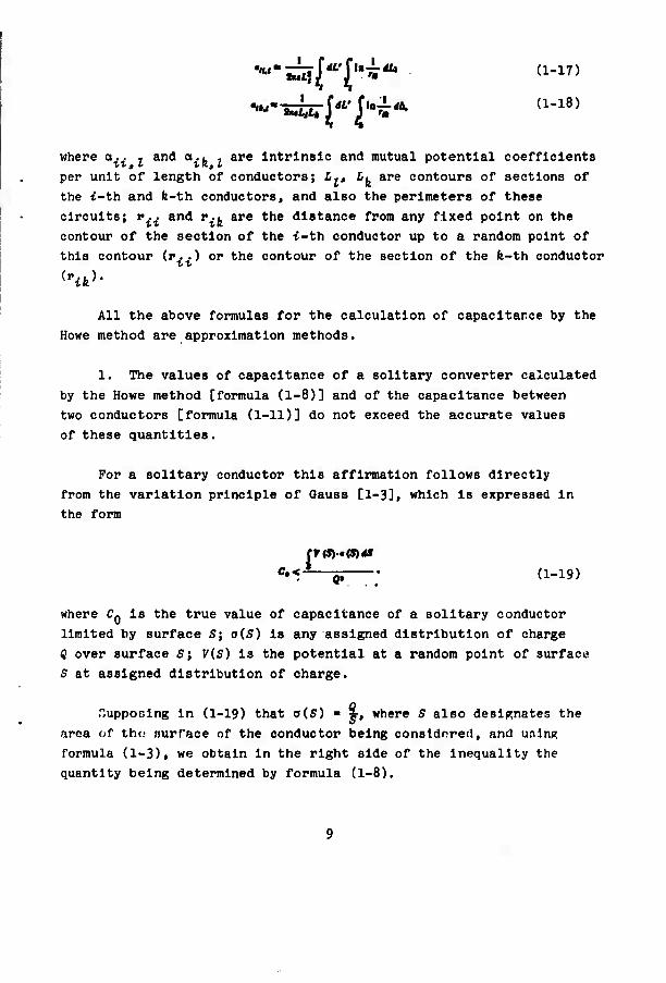
where a.. , and a.. . are Intrinsic and mutual potential coefficients per unit of length of conductors; £-, L, are contours of sections of the i-th and fe-th conductors, and also the perimeters of these circuits; v.. and v.. are the distance from any fixed point on the contour of the section of the i-th conductor up to a random point of this contour (r. .) or the contour of the section of the fe-th conductor
^fe)-
All the above formulas for the calculation of capacitarce by the
Howe method are approximation methods.
1. The values of capacitance of a solitary converter calculated by the Howe method [formula (1-8)] and of the capacitance between two conductors [formula (1-11)] do not exceed the accurate values of these quantities.
For a solitary conductor this affirmation follows directly
from the variation principle of Gauss [1-3], which is expressed in
the form
rF(S)«(S)4S c»<-*—p (1-19)
where C« is the true value of capacitance of a solitary conductor limited by surface S; o(S) is any assigned distribution of charge Q over surface S\ V(5) is the potential at a random point of surface S at assigned distribution of charge.
Supposing in (1-19) that a(5) - *, where S also designates the area of tho surface of the conductor being consldrred, and unlnp; formula (1-3), we obtain in the right side of the inequality the quantity being determined by formula (1-8).
For the capacitance between two conductors the proof is con-
ducted analogously.
2. The values of Intrinsic and mutual potential coefficients
[formulas (1-15), (1-16)] are greater than the true values of these
quantities.
3. For conductors of one and the same (or close) layout the
error of the method of mean potentials is less, the more uniform the
equilibrium distribution of charge on these conductors. Specificallyi
the relative error of calculation of capacity of any straight
solitary wire (or cylindrical conductor) with the assigned form of
cross section Is less the greater the ratio of its length to maximum
dimension of cross section, its lowest value is reashed when the
section is round;
the relative error of calculation of capacitance of a flat
rectilinear plate of assigned area is less the greater the ratio
of dimensions of the plate;
the relative error of calculation of capacitance of solitary
conductors in the form of right polyhedrons inscribed in a certain
sphere or described relative to it is less the greater the number of
sides;
the relative error of calculation of capacitance between two
plates of the same form and dimensions in one plane is less the
greater the ratio of distance between plates to any dimension of
them.
KrroTt: of calculation of capacitances are numerically evaluated
by the Howe method taking into account the affirmations, by means
of comparison of the corresponding approximation expressions with
accurate ones (see Example 1-2).
10
Example 1-1. Let us determine the capacitance of a conductor
In the form of an a x t rectangular plate. Using formula (1-8)
let nz precalculate ]—• For this let us Introduce a rectangular
system of coordinates the origin of which is compatible with one of
the peaks of the rectangular contour of the plate and direct the axes
along the sides of this contour. Then the value of f— at a certain
point with coordinates *.; ^ (0 < «1 < a; 0 < j/, < b) will be determined by the expression
Repeatedly integrating,1 after the corresponding conversions we obtain
m *
Substituting the obtained expression into formula (1-8), we
obtain the following approximation expression for the capacitance
'Using the symmetry of expression f(.t., y,) relative to the
quant It! on entering It and also the obvious relation ]?(•-•)*-
-JtW*. where ^ is a random function, it is sufficient to carry
out integration of only one of the components entering /(x., y1),
11
of the plate considered:
C,»2r.,.
a«6 Arsh-j- + aM Anh — + — (at + ^—L(ai + K)T
Example 1-2. Using the Howe method, let us determine the value
of the capacitance of a conductor in the form of a solitary circular
disc of radius F.
Using formula (1-8) again, let us precalculate
j*-Hi^.?-*-. •"'(*)• where E is a complete elliptical integral of the 2nd kind with
modulus fe ■ r,//?.
Then
u g i
Substituting the obtained expression in formula (1-8), we find that the capacitance of a circular disc calculated by the Howe method is equal to
Ctm^-tUKm 7,40*9.
The accurate value of the capacitance of the disc is equal to Be/?. Thus, the relative inaccuracy of the calculation of the capacitance of a solidary disc by the Howe method is about 7.5%.
In calculation of capacitance of closed shells, a fictitious charge can be considered distributed not only over the surface, but also in the volume of the bodies replacing these conductors.
12
In this case the general scheme of using the method of mean
potentials remains constant; however, the features of Its applica-
tion depend on the character of distribution of charge in the volume
of bodies.
With continuous distribution of charge with assigned volume
density p(w), the course of calculation differs only by the fact that
to determine potential at points of the surface of the body Instead
of formulas (1-3) It is necessary to use formula (l-'O. This does not
usually lead to simplification of calculations since Instead of surface
Integrals entering (1-3), it is necessary to reckon integrals in terms
of volume.
With continuous distribution of charge along certain lines in a
volume of bodies (it is expedient to use such distribution in calcu-
lating the capacitance of conductors of drawn out or axisymmetric
form) In formula (l-1*) the volume density of a charge must be replaced
by linear density, the volume Integral must be replaced by a curvi-
linear Integral, and calculations are simplified. Thus, for a
solitary axlsymmetrlcal shell
CtmHtSLl' [i-m where L is the segment of the axis of symmetry Inside the conductor (and also the length of this segment); S is the surface of the conductor (and also Its area); r is the distance from the fixed point
of the surface S to the running point of the axis L.
With discrete distribution of charge in the volume of bodies,
the potential at every point of surface of the body is calculated
as the sum of potentials of point charges.
1-3. Method of Grounds
During the calculation of capacitance by the method of grounds
the surface of each of the bodies replacing the conductors is
divided Into a number of grounds the simplest possible form of which Is selected and the dimensions of which are so small that the fictional distribution of charge in the limits of each ground can be considered uniform.*
The surface of each ground is ascribed a fixed potential V. equal to the potential at any one (characteristic) point of this ground.
At sufficiently small dimensions of grounds, the method of
location of characteristic points on their surface has comparatively
little effect on the results of calculation. Therefore, it is usually
selected only from conditions of simplicity of calculations.2
The potential at the characteristic point of each ground can be
determined with the aid of formula (1-3) and with the accepted law
of fictional distribution of charge
V'-tü*** (1-20)
where V^ is the potential at the characteristic point of the fe-th ground; n Is the number of grounds; a^ is the density of a charge on the surface of the t-th ground; Si is the surface of the i-th ground; r^ is the distance from the characteristic point of the fe-th ground
to a random point on the surface of the t-th ground; "u"]-^-
The value of coefficients a^ are determined only by geometric parameters of grounds and their mutual location. When the distance
between any two grounds considerably exceeds the dimensions of at
least one of them (for example, the t-th), the quantity UL. can be Rt
determined with sufficient accuracy as the ratio of the area of the
'."oe examplon of use of the method of grounds in works [1-5, 1-6].
'The location of characteristic points on the surface of identical grounds are usually selected identical, and on the surface of geometrically similar grounds similar.
1H
i-ttt «round to the distance between the characteristic points of the t-th and fe-th grounds.
The values of potentials of grounds (V. - v.) found from (1-20) In the limits of the surface of one conductor are equated with one and the same constant.
For a solitary conductor this value 04) can be selected at
random. This leads to the following system of linear algebraic
equations relative to unknown values of density of charge on the surface of each ground1
a,,», + OK«, + i.. + oU9m — 4=M,
««I»I + «»A + ... + ttM9,JiaÄ.
(1-21)
Hence the charge density on the surface of the fe-th ground Is
»»-•»niM-^-, (1-22)
where
A- «a "i» • • • «t«
and Aj^ Is the determinant formed from A by replacement of all the elements of the fe-th column with ones.
At the found values of ofe the total charge of the conductor in
general (at random separation of surface of conductor Into grounds)
In a number of cases from conditions of symmetry It Is possible knowingly to show certain grounds with the same charge density. In these cases the number of unknowns in (1-21) Is reduced.
15
Is determined by the formula
Q-^i.yl.i-^jS.A. (1-23)
where ■?, Is the area of the fe-th ground.
If all the grounds are Identical, then
Q-.4*M-£.JjA». (l-23a)
where S Is the total area of the surface of the conductor.
The obtained expressions for total charge lead directly to the
following approximation expressions for the capacitance of a solitary
conductor:
a) In general
C(aI4«.lJ|st.At: (1-21)
b) for Identical grounds
C,Ä4ia-i-J|Ä^ (l-24a)
During the calculation of capacitances in a system of two and more conductors, direct utilization of the method of grounds is difficult since it leads to lengthy computations. Therefore, In these cases the method of grounds is used, as a rule, to calculate coefficients of electrostatic induction with subsequent conversion to values of capacitance on the basis of the relationships given In i V-l.
Lot the number of conductors in the system be equal to S, and the number of grounds into which the surface of the p-th conductor Is divided n (p ■ 1, 2, ..., ff). Then the potential at the characteristic point of each ground can be found from formula (1-20)
when n-^Hp. Then the potentials of all platforms on the surface of
16
each conductor should be equated with one and the same constant
4 (p • 1, 2, ..., ff); however, the values of the constants A can no P p longer be assigned at random (as In the case of a solitary conductor),
but must be selected taking Into account the conditions Indicated In
V-l and V-5. These conditions are the simplest In the calculation of
coefficients of electrostatic Induction since the potentials of all
conductors, except one, should be taken equal to zero.
Let us assume, for example, that it is necessary to determine
the Intrinsic coefficient of electrostatic Induction for the p-th
conductor and the mutual coefficient of electrostatic Induction for
the p-th and i^-th conductors (p, q - 1, 2, .,., N, p ft q). Without losing generality one can assume that areas with numbers 1, 2, ..., n belong to the surface of the p-th conductor, and areas with numbers
n + 1; n + 2, •...»»_ + «- belong to the area of the q-tYi conductor. Furthermore, let us assume that the potential of the p-th conductor
is equal to a certain constant A.
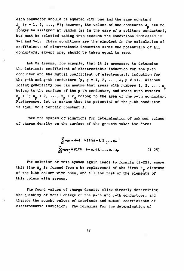
Then the system of equations for determination of unknown values
of charge density on the surface of the grounds takes the form:
Tau«,. «Mil Wlth«-I. % .... «^
i|"*rt-0with »-«, + 1 «, + ,,. (1-25)
The solution of this system again leads to formula (1-22), where
this time A. is formed from A by replacement of the first n elements p of the fe-th column with ones, and all the rest of the elements of this column with zeroes.
The found values of charge density allow directly determining the quantity of total charge of the p-th and q-th conductors, and thereby the sought values of intrinsic and mutual coefficients of electrostatic induction. The formulas for the determination of
17
these coefficients have the form:
A t-«^fi
(1-26)
(1-27)
The given formulas (l-2'l), (1-26) and (1-27) are approximation
formulas, and, as can be shown, give underestimated values of the
capacitance of a solitary conductor and of coefficients of
electrostatic induction in a system of two and more conductors.
From the essence of the given method it is clear that the
Inaccuracy of calculation from these formulas is less the smaller the
grounds into which the surface of the conductors is divided. At
rather small sizes of grounds the accuracy of calculation of capaci-
tance by the method being considered can be brought to any required
limits and, in particular, can be higher than when using the method
of mean potentials.
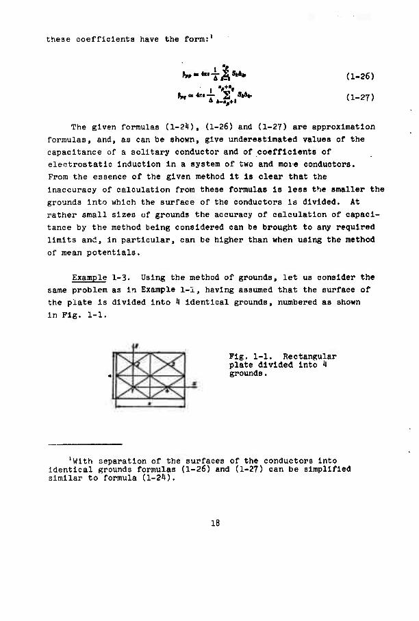
Example 1-3. Using the method of grounds, let us consider the
same problem as in Example 1-1, having assumed that the surface of
the plate is divided into 1 identical grounds, numbered as shown
in Pig. 1-1.
Pig. 1-1. Rectangular plate divided into t grounds.
'With separation of the surfaces of the conductors into identical grounds formulas (1-26) and (1-27) can be simplified similar to formula (l-2it).
18
Using a rectangular system of coordinates (Pig. 1-1) and selecting
as characteristic points the points of Intersection of diagonals of
each ground. In accordance with formula (1-20) we find:
«« HI
+fA"hT-fA"h4- Jo/4 UI4 «0/4 UI4
S> «/4 1/4
-TA"h- + TAr,hT + TAr,hi-
Because of the symmetry of the location of grounds a1 ■ Op ■ = a3 - Oj, - a0; furthermore, with the accepted division of surface
into grounds a11 - a22 - a33 - a^^; a12 - a^; a13 - a^. Therefore, in system (1-21) it Is sufficient to keep only one equation, whence
,,« in -j-1— = 4«» (a Arsh -L + 6 Arsh -2- + -^ Arsh -i- -f
^-f^X + T^T + T^i)"-
Using then formulas (l-23a) and (l-2l)a), we find that with the
means shown of division of plate into grounds, its capacitance is
C#22 4ci-
9 4 ok 4 *
+ -f Ar.bÄ + ^A,A »
19
l-t. The Method of Equivalent Charges
The method being considered consists of determination of the
distribution of charges In the volume of bodies replacing conductors
In the form of closed shells at which the surface of these bodies is
äquipotential.1 If such distribution of charges Is found, then the
values of capacitance In the system of conductors can be determined
according to the formulas shown In § V-l, substituting In place of
potentials of conductors potentials of surfaces of bodies, and Instead
of charges of conductors values of the total charge In the volume of
each body.
There Is no general means of determining the distribution of
charges creating electrostatic fields with assigned configuration of
equlpotentlal surfaces In existence at present. Therefore, In
determination of capacitance from the method of equivalent charges,
the reverse method Is usually employed: assigning this or that
concrete distribution of charges, the form of equlpotentlal surfaces
of electrostatic field Is determined for each of them, and thereby
a certain "set" of distributions of charges which create known
fields Is obtained. Using It, It Is possible in a number of cases
to find such a distribution of charges for which the form of equl-
potentlal surfaces coincides (or closely enough) with the form of
surfaces of the conductors considered.
Sometimes the required distribution of charges can be found also
directly from the assigned form of the surface of conductors.
Thus, during calculation of capacitance In a system of conductors
houndod by surfaces of spherical form, the required distribution of
charge can be found directly by means of utilization of the following
known features of electrostatic field of point charges.
lAt the shown distribution of charge the electrostatic field out- side the surface of the bodies coincides with the electrostatic field of the system of conductors being considered. In this sense the charges concentrated In the volume of bodies are equivalent to the charges distributed over the surface of the conductors.
The method considered Is also sometimes called the method of "consolidation" or "congelation" of equlpotentlal surfaces.
20
1. In the field of point charge q any spherical surface with center at the point of location of charge Is equlpotentlal. If the potential of this surface Is equal to 4, and the radius Is equal to a, then the charge located at the center of the sphere is <? ■ J<irea A,
2. In a field of unlike point charges q, and q* separated by a distance of d, there Is a surface of zero potential having the form of a sphere, the center of which Is the line passing through the points of location of charges, and the radius of the sphere B and the location of Its center are determined from the relationships:
l*i-*il-4
A,«—JL*. (1-28)
where h, and h- are the distances between the points of location of the charges q, and (jp and the center of the sphere.
At assigned radius of sphere R, and quantity and location of one of the charges (for example, charge q-*), relationships (1-28) can be used to determine the quantity and location of the second charge q2, which is called the reflection of charge q, relative to the sphere or simply the reflected charge.
The application of these features allows showing the means of determination of distribution of equivalent charge in a volume of bodies bounded by spherical surfaces. In general form this method consists of the fact that, locating In the center of each sphere a charge of appropriate quantity, its influence on the potentials of the romaining spheres is compensated with the aid of a definitely selected system of reflections.
Example 1-4. Let us determine the capacitance of a solitary conductor formed by two spheres of radii a and h, which intersect at an angle of Tr/2; a > bt and the distance between the centers of spheres I > a - b (Pig. 1-2).
21
Flg. 1-2. A solitary conductor formed by two spheres with radii a andb(a > b), Intersecting at right angles.
Taking the potential of the conductor to be equal to the constant A, we locate In the center of a sphere of radius a (sphere 1) a point charge q 10 'lirea»^.
In the field of this charge the surface of the sphere 1 acquires a potential A, but the potential of sphere 2 Is Inconstant. Reflecting charge ^ relative to sphere 2. we find that the reflected charge Is
9« ft» - —tet ., ** . Ä V* + * . V-M^
and Is at a distance of
»„-. Va' + t«
from the center of sphere 2, I.e., at a distance of
*:.-i/.»x^-^_ _ *
from the center of sphere 1.
In the field of charges q1Q and <?11 the potential of sphere 2 Is equal to zero, and sphere 1 is not equlpotentlal. To restore constancy of potential of sphere 1 we reflect relative to It charge ?11. The reflected charge Is *■
and is at a distance of ^ - <^J^.^Y^rr^ from the center of
sphere 1, i.e., at the center of sphere 2.
22
From the means of selection of quantity and location of charges
q,Q, q^ and «j.g. It Is clear that In an electrostatic field Induced by them the potential of each of the spheres considered Is constant
and equal to A.
Summarizing the found quantities q.Q, q,. and ^jp» we flnd that the equivalent charge Is
Q - »i« + *u + »» -
\ W+* }
Therefore, the capacitance of the conductor being considered Is
Example 1-5. Let us determine the capacitance of a solitary
conductor formed by two adjoining spheres of equal radii (Pig. 1-3).
Fife. 1-3. Conductor formed by two tangent spheres of equal radii.
Assuming again the potential of the conductor considered equal
to i4, let us first pick the distribution of equivalent charge at which
one of the spheres (sphere 1 for sure) has potential equal to 4,
and the other has potential equal to zero.
The required value of the potential on sphere 1 Is obtained,
as before, placing In Its center a point charge q1Q = kitcaA, where a Is the radius of the spheres. However, the potential of sphere 2
In this case Is not equal to zero. To achieve zero potential on
sphere 2 we reflect charge q1Q relative to this sphere. In this case we obtain the reflected charge q11, the quantity and location of
which Is shown In Table 1-1. In the field of charges q1Ci and q,.
23
Table 1-1. Quantity and location of Initial and reflected equivalent charges for the conductor shown In Pig. 1-3.'
* V» 9fy
0 1 3a 0
1 ~T a t
8 i >
4a 3
3a 8
3 i ~ 4
3a 4 h
4 1 5 i- f-
5 1 • i- i-
(-IJ» r <-i)»+,i [-^l- f.+ . ll'- »+i J-
lCfe and 02Cfe are the
distance of the point of location of charge q...
from the centers of spheres 1 and 2, respectively.
the potential of sphere 2 is equal to zero, but the potential of
sphere 1 is inconstant. To restore the constancy of this potential
we reflect charge q^ relative to sphere 1, finding the charge shown in Table 1-1 q^' Continuing this process (see Table 1-1), we see that the required values of potentials of spheres can be achieved
only with an Infinite number of reflections; the fe-th reflected charge 1c
»!*'
24
In completely analogous manner a distribution of equivalent
charges <j2fe, can be found with which the potential of sphere 2 is
equal to A, and the potential of sphere 1 is equal to zero. In this
case it is obvious that q^ ■ ^gfe*
In the total field of all charges found in this way the potential
of each sphere is equal to one and the same constant A. Therefore,
in this case the equivalent charge is
1rlf -aw*-tot
Thus, the capacitance of the conductor considered is
C« - Sna-lii %
The scheme of application of the method of equivalent charges
for calculation of capacitance between two conductors is analogous
to the scheme of calculation of capacitance of solitary conductors,
An example is the calculation of capacitance between two spheres
given in [1-4].
25
CHAPTER 2
AUXILIARY METHODS IN THE DETERMINATION OP CAPACITANCE
2-1. General Remarks
The methods considered In the present chapter pursue the objective of bringing the problems of determination of capacitance to a form permissible for calculations or to a form simplifying them. Such methods will subsequently be called auxiliary methods.
The majority of auxiliary methods consist of geometric conver- sions of systems of conductors and are based on the fact that In some of these conversions the values of capacitance remain constant or vary In a known manner. If such conversion Is carried out, then the problem bolls down to calculation of capacitance In the converted system, which can be done either by methods of direct determination of capacitance or by means of calculation of electrostatic field.
Some of the auxiliary methods are based on simplification of the problems of calculation of electrical field (and thereby of capaci- tance) with constant geometric parameters of the system of conductors. Such methods consist In Introduction of the relief functions, which are connected In a known way with the potential of the electrostatic field, but satisfy simpler boundary conditions. If the Introduced auxiliary functions satisfy the Laplace equation, then the problem of their calculation turns out to be simpler than calculation of the electrostatic field.
26
2-2. Method of Conformal Converalons
The method of conformal conversions Is used to calculate capacitance In plane-parallel systems consisting of two or more conductors. The basis of the method Is the feature of capacitance to remain constant during conformal conversions of shown systems (the invariance of the capacitance relative to conformal conversion).
Let us recall that conformal conversion Is geometrical conversion In which the angles between any two Intersecting lines remain constant, and the length of all Infinitesimal segments passing through the given point of the plane changes the same number of times. Conformal con- version Is described by the analytical function of a complex variable on condition that this function Is unambiguous, and Its derivative In the reflected area nowhere turns Into zero. The analytlclty of the function of the complex variable W(z) ■ t(x, y) + tiK«, y) Is checked with the aid of the conditions of Cauchy-Rlemann:
•t-its Ä—ft.' t* it dg ax
The Invariance of capacitance relative to conformal conversion
permits replacing the problem of determination of capacitance of any
plane-parallel system of conductors by calculating the capacitance
of another system obtained from the Initial system by means of one or
several repeated conformal conversions. If, especially, the Initial
system can be reduced to any system with known capacitance, then It
thereby ceases to be necessary to calculate capacitance.
With practical utilization of the method considered, the section
of the plane-parallel system of conductors Is taken as the plane of
the complex variable «, and a conformal conversion /(«) Is selected
as a result of which the system takes a simpler form permissible for
'The reader will find more detailed Information on conformal conversions In numerous works on the theory of functions of complex variable, for example. In works [2-1 to 2-*l].
27
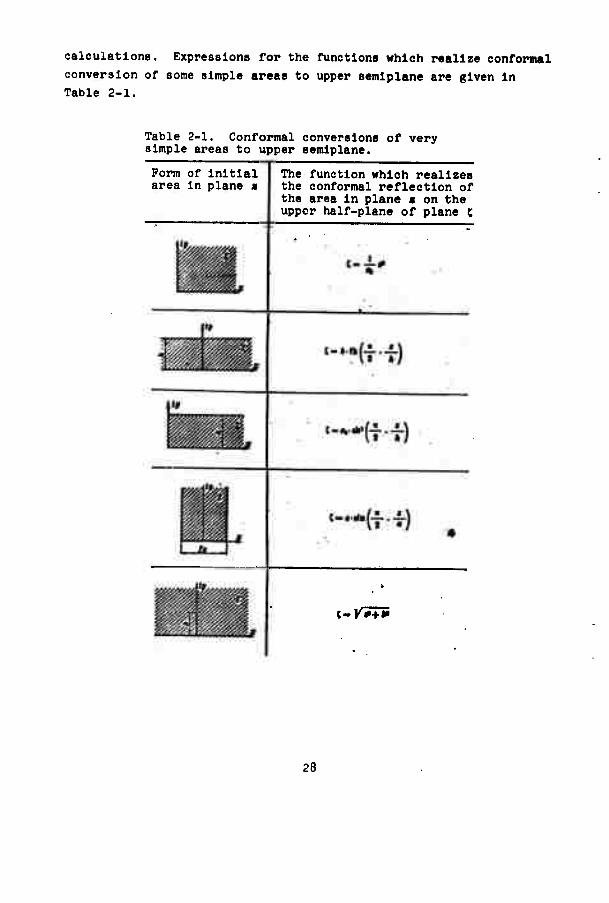
calculations. Expressions for the functions which realize conformal
conversion of some simple areas to upper semlplane are given In Table 2-1.
Table 2-1. Conformal conversions of very simple areas to upper semlplane.
Form of Initial area In plane a
The function which realizes the conformal reflection of the area In plane a on the upper half-plane of plane c
i~V7+*
28
Table 2-1 (Continued).
Form of Initial area In plane a
The function which realizes the conformal reflection of the area In plane a on the upper half-plane of plane c
'-'■mi
when •*». (..* + *. when«-»
St
Note. a0 - the dimensional coefficient of length, numerically equal to one.
In a number of problems encountered In practice the geometry of systems proves to be so complex that It Is Impossible to carry out Its conformal conversion to a form permissible for calculations. In these cases use Is sometimes made of methods of approximation conformal conversions (see, for example, [2-'»]).
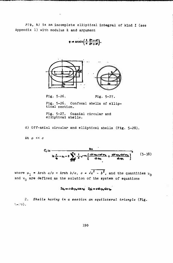
Example 2-1. Let us determine the capacitance (per unit of length) between an Infinitely long elliptical cylinder and an Infinite band, the sections of which are shown in Fig. 2-la.
Pig. 2-1. Elliptical cylinder and Infinite band in boundless homo- geneous medium: a) initial system; b) auxiliary system obtained by cutting the initial system with a plane of its symmetry; c) reflected system In plane r,.
* * 4
29
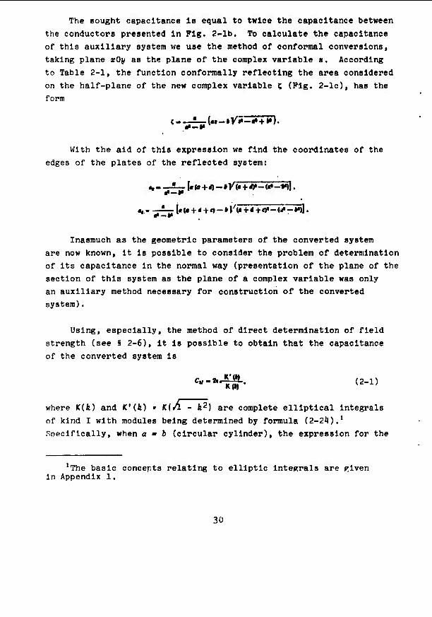
The sought capacitance Is equal to twice the capacitance between
the conductors presented in Pig. 2-lb. To calculate the capacitance
of this auxiliary system we use the method of conformal conversions,
taking plane xOy as the plane of the complex variable a. According to Table 2-1, the function oonformally reflecting the area considered
on the half-plane of the new complex variable C (Pig. 2-lc), has the
form
With the aid of this expression we find the coordinates of the
edges of the plates of the reflected system:
«,-—1—I<r(<r+i)-»y(« + «0,-(«'-*,>l. flP —H
«•- " ioJ« + < + e)-»1/(«+4+«)«-<J«-»,)l. «•-*•
Inasmuch as the geometric parameters of the converted system
are now known, it is possible to consider the problem of determination
of its capacitance in the normal way (presentation of the plane of the
section of this system as the plane of a complex variable was only
an auxiliary method necessary for construction of the converted
system).
Using, especially, the method of direct determination of field
strength (see § 2-6), it is possible to obtain that the capacitance
of the converted system is
Cu-*^Ä.. (2-1)
where K(fe) and K'(k) • K{Ä - fe2) are complete elliptical Integrals
of kind I with modules being determined by formula (2-2'»).'
Specifically, when a ■ i (circular cylinder), the expression for the
'The basic concepts relating to elliptic integrals are Riven In Appendix 1.
30
module of elliptical Integrals takes the form:
Inasmuch as capacitance is Invariant relative to conformal
conversion, formula (2-1) determines the capacitance of the system
depicted in Fig. 2-lb. Thus, the sought capacitance of the initial
system (Fig. 2-la) is determined by the expression
c,*u-
Example 2-2. Let us determine the capacitance (per unit of
length) between two conductors, each of which is formed by the
Joining of two infinitely long bands depicted in Pig. 2-2a. Using
the general features of capacitance (i V-2), it can be established
that the sought capacitance C, is four times as great as the capaci-
tance C,, of the auxiliary system shown in Fig. 2-2b,
C| - 4CU.
a)
1 ■* * - 'S -i -• • 1 -
Fig. 2-2. System of two conductors, each of which is formed by the Joining of two symmet- rically located Infinite bands; a) initial system; b) auxiliary system obtained by means of cutting the Initial system with the plane of its symmetry; c) reflected system in plane c.
To detect capacitance C-, we use the method of conformal con- versions. Taking the plane of section of the auxiliary system as the plane of the complex variable a, let us select the reflecting
31
function In the form of C-—-^. which, as Is evident from Table 2-1,
converts the auxiliary system considered Into a system of two plates lying in one plane (Pig. 2-2o). The capacitance (per unit of length) between these plates is determined by the above formula (2-1) If the modulus of elliptical Integrals Is assumed to be In It
kmt/P + W + l . (2-2)
Thus the sought value of capacitance Is
Ci-8.-51. K
where the value of the module of Integrals Is determined by expression (2-2).
2-3. The Method of Spatial Inversion
The method of spatial Inversion1 Is applicable during calcula- tion of capacitance of solitary conductors In a homogeneous medium and Is based on the use of geometrical conversion of the surface of these converters by their reflection reflective to the sphere.
Reflection (or Inversion) relative to a certain sphere of radius /?« (the radius of Inversion) Is geometrical conversion In which any point with spherical coordinates r; 6; ^ becomes another (Inverted)
2 point with coordinates RQ/*", 6; ♦• The locus of Inverted points of a certain surface forms an Inverted surface, which In a number of cases has a simpler form than the original. The determination of Inverted surfaces Is carried out either according to an assigned equation of Initial surfaces (by replacement In It of the coordinate
r with the coorfllnate r, ■ A-Zr) or by means of direct construction.
lDo not confuse with the method of plane Inversion (reflection relative to a circle), which Is a special case of the method of conformal conversions.
32
The latter is uubstantlally facilitated by the fact that spatial
inversion keeps constant the angles between any two Intersecting lines.
In using the method of Inversion one ought to have In view that
a reflection relative to a sphere Is reversible; therefore, any of
the surfaces that correspond to each other can be considered both
original and inverted.
A number of very simple examples of Inversions are given in Table 2-2. The capacitance of a solitary conductor the surface of which is converted by means of reflection relative to a sphere can be determined according to formula [2-5]
C-to-Ri-K* (2-3)
where e Is the specific Inductive capacitance of the medium; VQ Is so-called normalized potential In an Inverted system.
To determine potential VQ It Is necessary:
1. Considering an inverted surface a surface of a grounded
conductor (.V - 0), to dispose in the center of inversion a point charge qQ numerically equal to -'lire.
2. Having calculated the electrostatic field of the shown
point charge inside the grounded Inverted surface,' to find the
density of the charges Induced on this surface from the relationship
—£L- where u is the potential of the found electrostatic field, and n Is
the internal normal to the Inverted surface a.
3. Using formula (1-3), to find VQ as the potential in the center of Invernlon being Induced by Induced charges.
'This problem coincides with the determination of the Green function for an Inverted surface (see § 2-6).
33
Table 2-2. Spatial Inversion of certain very simple surfaces.
Initial surface Inverted surface
Sphere of radius R encom- passing sphere of Inversion and concentric with It
A sphere of radius
*5 «•-• encompassed by a
sphere of Inversion and concentric with It
A sphere of radius R the center of which Is at a dis- tance ot b{b > R + RQ) from
the center of Inversion
A sphere of radius
*i — *J-jj|—-j> the center
of which Is at a distance
of N-J^
ter of Inversion
from the cen-
A sphere of radius R passing through the center of Inversion
A plane passing at a
distance of *-—2- from Iff
the center of Inversion
Circular disc of radius R perpendicular to the radius of a sphere of Inversion at a distance of h from Its center
.-K
Part of the surface of a sphere of radius Ki--£-, cut by a rljrht circular cone the peak of whl^h In
at point ('■4) Ui'; anp'lf;
at the peak is «-«»rcig —
31
With the simple form of Inverted surface the calculation of
electrostatic field necessary for the determination of VQ Is simpler than the Initial problem of calculation of capacitance. Specifically,
when an Inverted surface If formed by the Intersection of several
planes, the electrostatic field of a charge <?- Inside a grounded
Inverted surface can be calculated using the principle of mirror
reflections, and the potential is found simply as the sum of the
potentials of reflected charges.
Example 2-3. Using the method of spatial Inversion, let us
determine the capacitance of the same conductor as In Example 1-k (two spheres Intersecting at right angles).
Considering the meridional section of this conductor (Pig. 2-3a),
let us dispose the center of inversion at one of the points of
intersection of circumferences, for example, at point A, and let us take the radius of inversion equal to the diameter of one of these
circumferences, for example, RQ - 2a.
Pig. 2-3. The conductor formed by two spheres intersecting at right angles with radii a and b (a > b): a)is the section of the initial and in- verted surface; b) Is the system of mirror reflec- tions of charge qQ ■ -knt, located at the center of Inversion relative to the inverted surface.
35
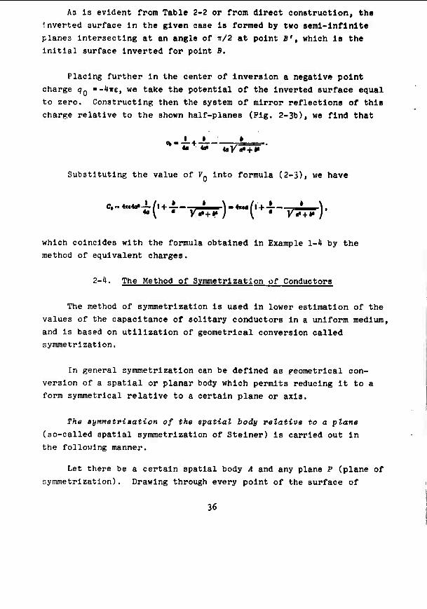
As is evident from Table 2-2 or from direct construction, the
Inverted surface In the given case la formed by two seml-lnfinite
planes Intersecting at an angle of ir/2 at point B't which is the initial surface inverted for point B,
Placing further in the center of inversion a negative point
charge qQ ■-'lire, we take the potential of the Inverted surface equal
to zero. Constructing then the system of mirror reflections of this
charge relative to the shown half-planes (Pig. 2-3b), we find that
Substituting the value of 7« into formula (2-3), we have
which coincides with the formula obtained in Example 1-4 by the
method of equivalent charges.
2-'(. The Method of Symmetrlzation of Conductors
The method of symmetrization Is used in lower estimation of the
values of the capacitance of solitary conductors in a uniform medium,
and is based on utilization of geometrical conversion called symmetrization.
In general symmetrization can be defined as freometrical con-
version of a spatial or planar body which permits reducing it to a
form symmetrical relative to a certain plane or axis.
The symmetrization of the spatial body relative to a plane (so-called spatial symmetrization of Stelner) is carried out in
the following manner.
Let there be a certain spatial body A and any plane P (plane of
symmetrization). Drawing through every point of the surface of
36
body A straight lines perpendicular to P, plotted on these straight lines symmetrically relative to P are segments equal to the total lengths of the chords being cut on the straight line being considered by body A. The locus of the ends of such segments forms the surface of a new body symmetric relative to plane P. Thus, for Instance, a hemisphere of radius a with symmetrlzatlon relative to any plane parallel to Its base becomes a condensed spheroid with axes 2a and a.
Completely analogously carried out Is symmetrlzatlon of the flat body relatively to any straight line In Its plane. One of the examples of such symmetrlzatlon Is given In Pig. 2-1».
a)
b)
Pig. 2-4. The symme- trlzatlon of an arbi- trary flat plate: a) Initial; b) symmetrized plate.
SymmetviBation of epatial body relative to an axie (Schwary symmetrlzatlon) consists In the following.
Given a certain spatial body A and any straight line L (axis of symmetrlzatlon). Drawing through the points of the surface A planes perpendicular to L, plotted at each of them Is a circle with center at L oqual in area to the section of body A by the plane being con- sidered. The locus of such circumferences forms a surface of new,
axlsymraetrlc body. Thus, for Instance, a cube with side a with this means of symmetrlzatlon relative to the axis parallel to one of Its
ribs becomes a right cylinder with altitude a and radius a/i".
Apart from this there are other, less widespread means of
symmetrlzatlon.
37
Use of the method of symmetrlzatlon when evaluating capacitance
Is based on the fact that capacitance by any means of symmetrized
solitary conductors never exceeds the capacitance of these conductors
in their original form [1-3], I.e., CQcm < CQ. Therefore, having determined In one way or another the capacitance of a symmetrized
conductor, the lower boundary of capacitance of the conductor of
Initial form can be determined In the same way.
If after a single symmetrlzatlon the form of the conductor still
remains so complex that the capacitance of the symmetrized conductor
cannot be found, then symmetrlzatlon Is carried out repeatedly, until
the form of the symmetrized conductor Is simple enough.1 Thus, the
method of symmetrization permits determining the boundary for the
capacitance of a solitary conductor of a form no matter how complex.
Example 2-4. Let us find the lower boundary of the values of
the capacitance of a flat plate in the form of a semicircle of radius a.
The capacitance of a conductor of the form considered cannot
be accurately calculated by existing methods. Therefore, we deform
the conductor in advance by means of planar symmetrlzatlon relative
to a straight line parallel to the base of the semicircle. The form
of a conductor thus symmetrized can be determined in the following manner.
Let us introduce rectangular coordinates (x, y) with origin at the center of the semicircle, having combined the Ox axis with its base. Then the connection between the coordinates of points on the
contour of the initial (x, y) and symmetrized (x,, j/,) plates will
bo dctorrnlneci by the equations
'With an infinite number of symmetrlzatlons the surface of any conductor of spatial form is converted into a sphere.
38
Jf J Hence —+ -2—-I, I.e., the symmetrized conductor has the form of a
planar elliptical disc with axes 2a and a. The expression for the capacitance of an elliptical disc Is known [see formula (4-3)]. Using It, we find that the capacitance of a plate In the form of a semicircle of radius a satisfies the Inequality
c, > —'*'"' - 8M-o.ra.
■m 2-5. The Method of Small Strains
The method of small strains Is based on replacement of con-
ductors of assigned (complex) form with other conductors of close
but simpler form, which permits calculating electrostatic field or
directly determining capacitance.
The strain of the surface of a conductor (as of any other body)
is commonly called small. If the displacement of the points with
respect to the normal to the surface of this conductor (h) is con- siderably less than its characteristic dimensions and Is a continuous
function of surface. Under these conditions the potential and strength
of the electrostatic field of the electrodes. Just as their capaci-
tance, can be presented In the form of an exponential series of h, the zero term of which characterizes the electrostatic field (or, the
capacitance, respectively) of an unstrained electrode. Limiting
ourselves to this or that finite number of terms of this series, it
is possible to obtain approximation expressions for an electrostatic
field or the capacitance of the considered electrodes of complex
form. The characteristics of utilization of the method of small
strains depend on the number and form of conductors entering the
system considered.
Let us consider for example, the problem of determination of
the capacitance of a solitary conductor of "almost spherical" form
39
[2-6], I.e., of a conductor the surface of which S can be determined by an equation of the form
r.ff,|l + t(i:f)|. (2_ij)
where r; 6; 41 are spherical coordinates of the points of the surface of the conductor; /?„ Is the radius of a certain sphere close to the surface of the conductor considered ("reference" surface); 6(6; ♦) is the comparative amount of the normal displacement of the points of the surface of the conductor from the surface of the sphere:
The quantity 6(6; $) can be presented in the form of 6(6; 0) ■ = ÖQ-FO; ^) where 60 is the comparative normal displacement at any fixed point of the surface of the conductor; P(e; $) is the function which characterizes the distribution of normal displacements with respect to the surface of the conductor, and
f(«:»)-'A.f+**
Assigning the fixed quantity of the potential of the surface
V\,-*. (2-5)
we will search for the potential of its electrostatic field in the
form
.V'-r + Wtir.hf}. (2-6)
where D and V^ir; 6; <|i) are the constant and function to be determined, respectively.'
■';ub:;t1tutln/'; thlü expression Into the boundary condition (2-5), we find that
'Let us note, that the given means can be generalized to the case when the "reference" surface selected is any (not only spherical) surface the form of which admits the solution of the external problem of Dlrlkhle for the Laplace equation.
HO
mm
Expanding the right side of this equation Into an exponential series of small parameter 6« and retaining the terms of this series containing 60 to a power not above the first, we obtain
>l - -^ + «.[-m «)-j—f ".(«< •: »)]• (2-8)
Inasmuch as the left side of equation (2-8) does not depend on
6 and <t>, the right side of It also should not depend upon these
quantities. This Is executed, especially, on condition that
-F9il)— + Vi(H**.i)-0. (2-9)
Prom (2-8) and (2-9) It follows that
O-J-ft«
M*.:»: ?)-/lf(»;rt. (2-10)
The last of the given equations can be considered the boundary condition for determination of a harmonic function iMr; 9; ^) at any point of an area outside a sphere of radius P*. Thereby the boundary surface of the problem was deformed into a sphere. Determi- nation of ^(r; 9; ^) with such a form of boundary surface can be carried out with any assigned type of function FO; ♦) by the method of distribution of variables (see, for example [2-7]).
Substituting the expression found for vAr; 6; $) In (2-6), it Is possible to obtain the approximation formula for the potential of the electrostatic field of the conductor considered, and then, using the general expressions (V-18), (V-l), approximately to find its capacitance. The approximation formula obtained by such a method for the determination of the capacitance of a conductor of "almost spherical" form has the form
C,«4«Ä,(l + Ml). (2-11)
where M is the coefficient with the first term of the expansion of function ^(r; 9; $) into an exponential series of 1/r. In general
til
■ ^-^-^^BBi^^-^^^^^—mmmmmmmBrmmmmimmmtm
this coefficient Is determined [2-7] by the formula
ft • «--^-J^j/ft ?)•!••* (2-12)
If the conductor Is axisymmetrlc, then
«--J-j'««»«*- (2-12a)
If more accurate formulas must be obtained, the equation of the
surface of the conductor can be assigned in the form
■*,[«+j§»{'.ftf)].
where
||«!'»ftT)| <«. '»(►.»)-'»(»:» + «•).
In this case, finding the potential of the electrostatic field in the form
V{r.*.i)--j-£tyl,fr.*i>
and using the given method, it is possible to obtain the following approximation formula for the capacitance of a conductor of "almost spherical" form
C,. 4nff,(l + M», + lj*lt+ .. . +»{«,).
where M is the coefficient at the fe-th term of the expansion of I'unctUm ^(r; 0; 0) Into an exponential series of 1/r.
F.xample 2-5. Let us determine the capacitance of a solitary conductor of axlsymmetric form the section of which Is described by the equation
'-*.II+ •.(«>•• «-cotl)|. IM<I.
12
11 I II I
With the analKned type of equation of the surface of a conductor
It;: capacitance can be determined only as a first approximation:
f(e) " cos 6 - cos 9. Substituting this expression f(e) Into formula
(2-12a) and Integrating, we find that M - 1/3. Then In accordance
with (2-11)
(■'*)• C, a ittR,
In using the method of small strains to calculate capacitance
In a system of two conductors, It Is possible to make use of the
fact that the relative change In capacitance between any two con-
ductors with any strain of them Is expressed [2-8] by the formula1
if.8> ^£-fc ' . (2-13)
where AC Is the absolute value of the change In capacitance; C Is the Initial capacitance between conductors; ?, and I- are the strength of an electrostatic field before and after strain, respectively;
f v is the volume of space In which the electrostatic field oeing considered exists (if one conductor wholly encompasses another, then v is the volume limited by the surfaces of the electrodes); At> is the change in v as a result of the strain of the electrodes.
If the strain of the conductors is small, then £.,=$_=? and
C f Mi- (2-1J4)
whore .'; Is the Initial surface of the conductors; h In the quantity of the normal mixing of the points of an initial surface during strain.
'The given formula can be generalized also to the case when the media filling the space between electrodes is heterogeneous. In this instance the specific inductive capacitance of the medium should be introduced by a factor into the subintegral functions of the numerator and denominator.
^3
Formula (2-14) allows approximately calculating the capacitance
of any little strained system of two conductors, if only the electro-
static field of this system In its initial state is known or can be
found.'
Example 2-6. Using the method of small strains, let us find an
approximation expression for capacitance (per unit of length) between
two noncoaxial cylinders, one of which encompasses the other (Fig. 2-5).
Fig. 2-5. System of two infinitely long cylinders with parallel axes dis- placed a distance of d from one another.
IT d < r < R, then the system being considered can be presented as the result of the small strain of a system of two coaxial cylinders
with radii P and r. Introducing polar coordinates p, ^ with center
at point 0, we find that for any value of ^ the amount of the normal
displacement of the surface of an interior cylinder is
*.,-M.^I-|/l-^)'*>«lf + -7-eMf]'
The strength of the electrostatic field In the space between
the coaxial cylinders is determined by the known formula
where A is the difference in potentials between cylinders.
'it is understandable, that any of the surfaces considered can be taken as the initial and strained surfaces.
HH
AC,
Taking Into account that In the case being considered ds - r-d^s dv ■ pdpd* and substituting the obtained values for h and E In formula (2-1'») we find
where E(d/r) Is the complete elliptical Integral of kind II.
Prom the general features of capacitance shown In i V-2, it
follows that the Increase In capacitance Induced by the strain con-
sidered Is positive, on volume C^ - C, + AC, where C, and Cn are the capacitances between coaxial and noncoaxlal cylinders, respectively.
Using the known expression for Cj, we obtain the following approxima-
tion formula for capacitance (per unit of length) between two non-
coaxial Infinitely long cylinders:
-Trf^l--^- (2-15)
To evaluate the Inaccuracy of this formula let us compare it
with the known accurate expression for capacitance between noncoaxlal
cylinders, which has (see i 5-*) the form
C«- -22 (2-16)
Mr
If we obtain, especially, r/R - 0.5, d/r - 0.3, then using formula (2-15) (Cn/2iTc) ■ 1.53 while the accurate value of this quantity calculated from formula (2-16) is equal to (Cz/2iTe) - 1.H8.
Thus, the comparative Inaccuracy of the calculation from formula
(2-15) In a given case is 3.4}{.
t5
^^^^_B^^BV^^V»-V»-V^^>-~^^_—
2-6. Methods of Auxiliary Functions
Methods of auxiliary functions consist In simplification of problems of calculation of electrostatic field (and respectively of capacitance) of conductors with their constant geometric form.
These methods are: a) the method of function of source (the method of Green); b) the method of direct determination of field intensity; c) and the method of consecutive approximations.
The first of the shown methods allows reducing uniform1 boundary conditions assigned on any surface to zero conditions; the second method makes it possible to replace compound boundary conditions on the surface of some plane-parallel systems with uniform boundary conditions; the third of the enumerated methods allows simplifying compound boundary conditions on the surface of some typical systems.
The method of funation of eouroe is based on use of the formula:
^.'i^'^43' (2-17)
where v^ is the potential at a certain point * inside the closed surface S; n Is an interior normal to this surface, and <; is a Oreen function of kind I determined in the following manner:
a) at any point inside surface S function £■-+/, where p is the distance from point S to a random point lying inside surface S or on this surface Itself; / is a random harmonic function (hence it follows that function G is also everywhere harmonic, except point r - 0, where it has the feature of type 1/r);
Let us recall that uniform boundary conditions are boundary con- ditions in which the values of one and the same function are assigned on the entire boundary, and compound boundary conditions are boundary f;ondltIonr, in which the values of various functions are assigned in Individual r.ectlons of the boundary surface (for example, in one ;;c;ctlon of the boundary surface potential is asalpned, and in another it-.-, normal derivative Is assigned). The solution of the boundary problems under compound boundary conditions, as a rule, is considerably more complex than under uniform boundary conditions.
1(6
b) at all points of surface S function C ■ 0.
Formula (2-17) makes It possible to calculate the electrostatic
field inside surface 5, if the values of the potentials on this
surface are assigned and the Green function G is found.
From the given determination of the Green function, it is evident
that it coincides with the potential of the electrostatic field of
a point charge numerically equal to ^ire and in a volume bounded by a
grounded metal surface 5, i.e., inside a surface with zero boundary
conditions. Determination of this auxiliary function in a number of
cases is simpler than solution of an Initial problem with nonzero
boundary conditions. Therefore, the method considered is widely used
both in the calculation of electrostatic fields, and in the direct
calculation of the capacitance of a number of conductors.1
Tht method of direot determination of field strength is used to calculate a certain class of flat electrostatic fields with compound
boundary conditions. This method Is based on the preliminary determi-
nation of auxiliary function Y(X, y) expressing the size of the angle formed by the vector of electrostatic field strength at any point of
the area considered with one of the axes of the Cartesian system of
coordinates. Function Y(«, y) Is harmonic [2-9]: it satisfies the two-dimensional Laplace equation. Boundary conditions for this
function can be established from conditions of orthogonality of power
and equipotentlal lines of field and, as is seen from the illustration
given in Pig. 2-6, can be uniform even when potential is assigned in
one part of the boundary surface, and its normal derivative is assigned on the other.
In connection with this the problem of calculation of function
Y(«, y) proves to be considerably simpler than the initial problem of calculation of potential under compound boundary conditions.
'Thus, calculation of capacitance by the method of spatial inversion actually bolls down to computation of Green function at the center of inversion (compare with S 2-3).
Fig. 2-6. Boundary conditions for a potential and an angle Y(«. y) in the case of a system of plates lying in one plane.
Having found this auxiliary function, it is possible then directly (passing the stage of determination of potential) to find the modulus of the strength of the electrostatic field of the system of conductors being considered from the relationships:
»i-'Q-IED- fc a/ * *1_ *(ln|E|) * 9M
(2-18)
From (2-18) it is possible, especially, directly to determine
the modulus of the strength of a planar electrostatic field created
by a system of any number of charged infinitely long plates lying in one plane.
In the points of this plane (y ■ 0) the modulus of the strength of the electrostatic field of the system considered is determined by the formula
IE!,..- '/nic-v+ijj
(2-19)
where xQi; yQi are coordinates of the special points of the field. I.e., of points in which E ■ 0; m is the number of special points; ak Is the coordinate of the edges of plates; n is the number of plater,; B Is a constant determined (along with the constants xQ.
1)8
^mm^^^mmmmm^^^m
and Vn;) from assigned charges or potentials of conductors. In
particular for an electroneutral system consisting of two plates
(Fig. 2-7),
IE| 5 (2-20)
Using formula (2-20), It Is possible to find that the difference in potentials between the plates Is
Vt-Vt~\\E\f,Jx~B\y/ * (2-21)
and the charge per unit of length of each plate Is
■,-*(\E\jlx~2tB\t/ * (2-22)
> 4 *
Pig. 2-7. Two Infi- nitely long plates lying In one plane.
Calculating the Integrals entering expressions (2-21) and
(2-22), we find that the capacitance (per unit of length) between the
plates considered Is
C- (2-23) Ki-K, KW '
wlipn- K(b) tu the complotc elliptical integral of kind T with modulu;-.
*. l/ <«,-«,)(«.-o.> V. (a,-a,)(a,-a,) *
K'(*)-K{VTIi?).
(2-214)
^9
<..I.M^H«PI-IWH>..:I|
The method of direct determination of field strength Is especially effective In conjunction with the above (5 2-2) method of conformal conversions. Thus, because of Invarlance of capacitance during conformal conversion, formula (2-23) determines the capacitance between any two infinitely long conductors, which as a result of this or that conformal conversion can be reduced to the form shown in Fig. 2-7. In this Instance the coordinates of the edges of plates are determined from assigned parameters of the initial system with the aid of an appropriate reflecting function (see Examples 2-1 and 2-2).
Example 2-7. Let us determine the capacitance per unit of length between the conductors presented In Pig. 2-8.
1 2 "A-* -''\
Pig. 2-8. Three Infinitely 3 long plates lying in one A *» plane; plates 2 and 3 are
* interconnected.
From the type of system considered it follows that in the electrical field induced by it, only one special point can exist which is located on plane y - 0; a^ < a;0 < a2. Therefore, assuming in formula (2-19) j/oi - 0, and m - 1, we obtain that the modulus of the strength of the electrostatic field on plane y - 0 is
Taking into account that the difference in potentials between electrodes 2 and 3 is equal to zero, we find
t'-*»* ..*, J I (^-^K-^H-^)
50
" ■ •' 'I" mm " iiiiMPRi«ipiiiN«in|n*PMHWiPPMipmRPRnpHpiiiiRii
whence
I.e.,
K(»i)
Using the expression found for field strength, we find, that
the charge per unit of length of every conductor is
Jl -a,
(* — *,) Hx
V(*~4V-'t)(4~''*j i r KW)
]/<-«? L K(*.) J
where »' =. ^ I -**; *1 ■ V ' - *? ■
The difference in potentials between the conductors considered
Is
f.r-^l'.-V.-/!
llonce we obtain the following expression for capacitance per unit of length of conductors considered:
r - j Ma . K(*i) I " Vt-Vt [ K(*) Kf*,) J'
The method of auaoeseive approximatione of boundary conditions allows reducing the solution of certain problems on calculation of
51
an electrostatic field with complex boundary conditions to the solution
of a succession of simpler problems. No general method of creating
this succession exists at the present time: selection of the Initial
approximation and method of construction of successive approximations
depend upon the type of this or that concrete system. Let us limit
ourselves therefore to illustration of the method of successive
approximations in the example of the calculation of the capacitance of a flat circular ring [2-10],
The problem of determination of the capacitance of a flat
circular ring under a strict posing requires the calculation of
electrostatic field under compound boundary conditions, and the plane
on which boundary conditions of various type are assigned has 2
boundaries1 (r = a and r " b). Solution of such problems Is very difficult, while the procedure for solving compound problems with
one circular boundary of boundary conditions is developed to a con-
siderably greater extent; therefore, we replace solution of the Initial
problem with solution of a succession of compound problems with one
boundary of boundary conditions.
In the first approximation we replace the ring considered
(Pig. 2-9a) with a circular disc of radius r - a (Pig. 2-9b). Using
the fact that the capacitance of any conductor is greater than the
capacitance of any part of it, we arrive at the inequality
which gives a rough estimate of the upper and lower limits of the capacitance of the ring.
To get a more accurate estimate we go to the second approximation,
which we construct in the following manner:
a) having assigned the potential of the disc (A) and having calculated the field of the system In Pig. 2-9b, let us find the
'."ubnequently we will call such lines boundaries of boundary conditions.
52
Flg. 2-9. To the creation of a system of successive approaches for calculation of capacitance of a plane circular ring: a) Initial system - a ring with radii a and b; b) 1st approximation - circular disc with radius a; c) 1st auxiliary system; d) 2nd approximation; e) 2nd auxiliary system; f) 3rd approximation.
charge on the surface of the disc o.Cr) and the potential In Its
plane /^(r) at r > a;
b) let us build an auxiliary system (Pig. 2-9c) In the form
of an infinitely extended plane, in part of which r < h charge
53
■ llll—^—»^
distribution Is assigned o2(r) - -OjCr); and In the remaining part of
which potential Is equal to zero;
c) having calculated the field of the system In Fig. 2-9c,
let us find the charge density and distribution of potential on the boundary surface;
d) superimposing the systems depicted in Pig. 2-9b and 2-9c,
we obtain the system boundary conditions for which is shown in Fig. 2-9d.
The built system differs from the Initial system in that in it
the ring a«0,a<r<fcisin the field of positive charge
distributed with density a2(r), but retains the same potential (A) as in the initial system. Hence it follows that the complete charge
of the ring in the system of Pig. 2-9d is less than the true charge, and
where Q^ is the complete charge of the surface a < r < i in the
system in Fig, 2-9b; Q2 is the complete charge of the surface a < r < i In the system in Pig. 2-9c.
The method of construction of the third approach is analogous to
the one considered: it is based on solution of the auxiliary problem
of finding the distribution of charge induced on a grounded flat
disc of radius a with negative charge distributed on part of plane r > a with density a3(r) - -a2(r) (Pig. 2-9e), and on the subsequent
superposition of the systems shown in Pig. 2-9d and 2-9e.
In a new auxiliary system thus built (Pig. 2-9f) a ring with
potential A is located in the field of positive charge distributed over the surface r < b with a density of a-(r). The complete charge or Uif rlnr In this nystem is greater than in the second approxima-
tion, but as before It is less than the true charge; therefore.
5^
we obtain a more accurate inequality for the capacitance of the ring in the form
where Q^ is the complete charge on the surface i < r < a in the system of Pig. 2-9e.
All the subsequent approximations of even order are built in the
same way as the second, and those of odd order are built in the same
way as the third approximation. As a result we arrive at a con-
vergent series of boundary conditions. In every subsequent approxi-
mation the complete charge of the ring is increased, remaining less
than the true value, while the potential of the ring remains constant;
therefore, the capacitance of the ring Is determined with ever greater accuracy.
Detailed computations of the capacitance of the ring by the
method of successive approximations are given in [2-10].
1. The material of this part ia divided Into three chapters.
In Chapter 3 the data are given on the capacitance of wires. In
Chapter 1 data on the capacitance of flat plates, and In Chapter 5
data on the capacitance of wires In the form of open and closed shells.
In all these chapters it Is assumed that the medium surrounding the conductors Is either uniform in infinite, or is bounded by one
flat impenetrable boundary. In the latter case capacitance Is
calculated by means of analysis of the auxiliary systems of conductors located in an infinite uniform medium and obtained by means of a
single mirror reflection of the initial system (see § V-2).
2. At the beginning of every chapter general remarks are given,
in which the geometric forms of the conductors considered are briefly
scanned, and the general characteristic of the data given on their capacitance is given.
3. The material of each chapter is arranged in increasing order or the number of conductors that form this or that system.
One ought to take account of the fact that the system formed
by the union of several conductors is considered one conductor;
In this case the effect of the connecting conductors on the capacitance of a system is assumed to be negligible.
4. For the majority of the systems of conductors considered
56
both accurate, and approximation formulas are given with indication of the limits of their applicability and accuracy. The latter is characterized by relative error
where C and C * are the accurate and approximation values of TOHH npHOSI
capacitance, respectively.
5. References to operations used in obtaining individual formulas, as a rule, are not given. However, for some typical systems the basic results obtained by various authors are briefly compared.
57
CHAPTER 3
CAPACITANCE OF WIRES
3-1. General Remarks
1. In this chapter formulas are given for calculation of the capacitance of wires, I.e., of conductors the form of which satisfies the conditions shown in i V-2. In all cases when nothing is said to the contrary, it is assumed that the form of the section of wire is circular.
2. In all the formulas below the distance between wires Is understood to be the distance between their axis.
3. All formulas given in this chapter are approximation formulas, and a majority of them are obtained by the method of mean potentials.
't. The limits of applicability of the given approximation formulas depend upon the relationship of the sizes of a wire and of the form of its axis; in mojt oases accuracy of formulas is evaluated by solving numerical examples.
3-2. The Capacitance of Solitary Conductors Formed by Wires Arranged in Infinite Space
1. The reotilinear wire of finite length (Pig. 3-1).
C(a! fcil
I«.' 4 NT J|»|<l,0H «h.« //a>10J,
58
mmm^^^ mm^
Pig. 3-1» A rectilinear wire of finite length.
When greater Inaccuracy la tolerable, the following less accurate formulas can also be used:
C,= inl i —
Cte*. 2«!
-4-
(3-2)
(3-3)
Example 3-1. To determine the capacitance of a rectilinear wire In air i - 0.5 m long and a ■ 0.025 m In radius.
To determine capacitance let us make use of formulas (3-l)-(;'-3) Taking Into account that for air •-••-■^•^o~• p/m, and using the
. 80 0,7117 180 170 0,9141 190 «5 0.7330 ITS 176 0,9156 188 90 0.75S m 160 0.9160 180
60
w^^^^mmmmmi^^m^^^m^
3. A wir» in the form of a airaular ring (Pig. 3-3).
Pig. 3-3. A wire In the form of a circular ring.
• ^—vT (3-5)
f|«|<2.0^hen «/a>IOI.
Example 3-2. To determine the capacitance of a circular ring and semiring In air and having a radius R ■ 0.1 m, the diameter of a section Is 2 a = 0.01 m -0,01 «/«-«,--j--«r* P/m).
Using formula (3-5) for the capacitance of the ring we obtain
c,«-!^L12±.6.w.io-"P-e,w pP. 3teta±5d.
• Old«
To determine the capacitance of a semiring we preliminarily find from Table 3-1 the value of parameter X. When 6 ■ TF parameter I ■ 0.916. Thus, for the capacitance of the semiring considered we have
c^-^ ,0|0-1< Vi.«r«P-*n pp.
The ratio of the found values of the capacitance a semiring and a ring is 0.5M, i.e., the capacitance of a semiring Is somewhat greater than half of the capacitance of a ring of the same radius. With decrease in R/a this difference is Increased.
4, Two interoonneoted parallel rectilinear wiree of finite length (Fig. 3-H).
61
•m^mmmmmmmmmmmmmmmm ^^^^^^•^^^^ ^^i^pw
Let us examine several cases:
a) 'fc - 0 (Pig. 3-5), then
■ii«tt—«t*
where
,»!Ädir[Arsh-5-+tA»«'-J-(t-7')Ar*f^i+x+
b) 6-0; Z,*.!,.!; a,.a,.a
C.«-,-
where *" f+ f-/T^-j/T^.
(3-6)
(3-7)
Fig. J-t. The gen- eral case of a soli- tary conductor, formed by the union of two parallel straight wires.
Pig. 3-5. The conductor shown In Fig. S-'«, when i - 0.
Kig. 3-6. The conductor ahown in Pig. 3-4, when A- - ^ + 2h.
When h > l/H
Sr* Pig. 3-7. Two joint Identical wires, arranged on one straight line.
'<?,=« *at
to-L+to2»±«. » »+i
(3-11)
S. Two in.eroonneated interseating or oroeeing reotilinear wires of finite length.
a) General case (Fig. 3-8).
63
ei-:» (3-12)
where
&•(»,
D«-K^ + 4-Vfcosv + 'p« P-l.«!«-!.«.
',«^.v..* Fig. 3-8. Conductor formed by two Intersecting or crossing rectilinear wires P, and P2 are parallel planes passing through wires 1 and 2, respectively; P, Is a plane perpendicular to P1 and P2; d is the distance between planes P, and P2; ^ is the angle between wire 2 and the projection of wire 1 on plane P2 (or, what amounts to the same thing, between wire 1 and the projection of wire 2 on plane P-^); «j, «2» and ^i» J/2 are the
coordinates of the ends of each of the wires reckoned along the line of their location from points 01 and 02, respectively.
6H
inmm ^mm
b) Perpendicular wires of equal length are located In one plane: i • 0; * ■ ir/ü; a^ - j^ - fc; «g - x1 - y2 - ^ - I (Pig. 3-9)
Ct=* (3-13)
,+C+W
Pig. 3-9. Two perpendicular lines.
When h " Q
Ctsat- Ud (3-11)
6. Several (n) interoonneoted identical parallel reatilinear wtree.
a) the wires are located In one plane at equal distance from
one another (Pig. 3-10).
Pig. 3-10. A system of n Identical Interconnected parallel wires In one plane at equal distance from one another.
When d/l « 1
C,: t*Ml
« [la — - 0.S07J + to-£-+ « (3-15)
65
""•'^■^■^"w"«" P i •~~~-*^^^m^^mimm^^m^^^^^mm^^ii^mimmmmmmM
where
3-2.
fl--r S'"!(«-i)i (»-«»i.
The values of coefficient B for n ■ 2-12 are given in Table
Table 3-2. Values of the parameter B which enters formula (3-15).
b) The wires are located evenly on the surface of a circular cylinder (Fig. 3-11).
Pig. 3-11. A system of n identi- cal interconnected parallel wires arranged over the surface of a circular cylinder.
C.« feul
In i-+ («_ i)|B2. +|ll2_»_|nr,|B-l..,|n^...I|B<•=Jll^,
.-2«/«. * (3-16)
When n « 2 this formula coincides with (3-9), and when n ■ 2-8 1L ieaü;; to the formulas shown in Table 3-3.
c) the wires are located on the parallel edges of a rectangular parallelepiped (Fig. 3-12).
Pig. 3-12. Pour identical rectilinear wires arranged on the parallel edges of a parallelepiped.
66
^^mm^^^mm^m^mmma
Table 3-3. Capacitance of conductor shown In Fig. 3-11 at various values of n.
Caloulatlon Capaoltanc«
JTt* Ctet «cti
In —-Hin-—1.0SJ
C»c tul
In —+ 3IQ —-2,615
C,- IOMI
In —+ 4ln- 3,138
C.« I9ni
In4- + Sln —-3,M0
C,. tend
«•4:+7|B-J~^6IB
When d > 5h
C,=! 8«l
In- (3-17) ZftAl
Example 3-3. To calculate the capacitance of the conductor :'.liowri In Klg. 3-il, when Z » 2.0 m; 2 a - O-Oi» m; /? - 0.5 m, at varlouü vuiueji oV n.
67
■
Using the formulas given in Table 3-3, we directly find
for n ■ 3
c. rj-^'-*^ »tfi-ur»,•- M^ pp. 0,02 04
for »■«
C« « rr *"*'*' 72.«- KT'» F . 78.8 pp.
",o^ + 3,,,^-2•e,8. for «-6
C.« .„ "^l** 79.».I0-»P - 79.5 PR
0,03 0,5
for «-•
lo-^ + 6.0ln-£=--3k5l 0,02 04
for »-• ' C.« ""»y, 9l.l0r«P-9I pp.
'-S^'-ij-^
Hence it is apparent that with increase in the number of wires from 3 to 6 the capacitance of the conductor being considered is increased 3^%, and with increase from 4 to 6 only 13%. This evidences significant mutual effect of wires.
7. Reotilinear wires oonneoted in the form of a polygon.
Approximation formulas for the calculation of capacitance of conductors in the form of polygons of various type are given in Table 3-1, and give an inaccuracy of not more than lOJ.
Example 3-1t. Disregarding the effect of earth, to determine the capacitance of a frame antenna in the form of a square with side I ■ 10.0 m with a wire 6 mm in diameter.
Using the formula of Table 3-'«, we find that the capacitance of the antenna considered is
C,«—iauüL*—-0.22.1(r*{p)-8aB pp.
0,003
68
Table 3-4. Formulas for calculation of capaci- tance of solitary conductors In the form of polygons formed by rectilinear wires.
if £-3.
Fora of clreilt
Calcjletlon system.
trlanfl«(
Squara
hoxaaon
lioloslt» tritneX»
trlan^lt
M r_
-u r*"
Oe prsltanoo
C,-- «cd
to-j- + l
to-i-+ 1.91
Iftul
^a-!-+2.m
C| oi 4«< io-i-+s.ie
O.TW
to4- + J.3l
C.a4r.l( 0.438
10-^- +I.«
0.5
|D1. + 1.» lnX.+ l.9
8. Wirea aonneoted in the form of epatial bodies.
tt) The wires are located on the edges of a cube (Fig. 3-13):
C,<=*. 34nl
to-j-+«^l (3-18)
b) Wires are located along the direotrixes of a right circular cylinder and along four of the generatrixes, lying in two naturally perpendicular planes (Fig. 3-11»).
69
Flg. 3-13. Conductor formed by wires on edges of cube.
Pig. 3-m. Conductor formed by the wires arranged along the direc- trix and four generatrlxes of a right circular cylinder.
When H/4R < 1
C.~ te«i(g*+tf)
-lng*+ ; Si .+i(,.a+l) • (3-19)
where K is a complete elliptical integral of the first kind (see Appendix 1) with modulus *„ l/. ***
V i 4IP+H*
3-3- The Capacitance of Solitary Conductors. Formed by Wires Arranged Near an Infinite Flat
Impenetrable Boundary
The formulas given In the present paragraph were obtained by the method of mirror reflection of the conductors being considered relative to a planar Impenetrable boundary. Some of the auxiliary systems obtained in this way coincide with those considered in the previous paragraph. In these cases calculation of capacitance bolls down to utilization of the formulas of appropriate sections § 3-2. The numerical examples given in the present paragraph concern basically the determination of the resistance of grounds on the basis of an analogy between conductivity and capacitance (see i V-4).
1. Reatilinear wire of finite length.
a) The wire is parallel to the boundary plane (Pig. 3-15):
c;~£. (3-20)
70
■ ' ' ' ■ ■ —-^^r^-»^—-———
iiuhn C'0 Is determined from formulas (3-7)-(3-9),
Pig. 3-15. Rectilinear wire of finite length parallel to a flat impenetrable boundary.
b) The wire is perpendicular to the boundary plane (Fig. 3-16);
(3-21)
where C0 when Ji » 0 is determined from formulas (3-l)-(3-3), and when h t 0 from the formula (3-11).
ft
I Pig. 3-16. Rectilinear wire of finite length perpendicular to a flat impenetrable boundary.
Example 3-5. To find the resistance R of horizontal and vertical grounds with radius a * 0.1 m and length Z = 1.0 m in ground with electrical conductivity y - 2.0'10"2 l/n-m, arrangad on depth: horizontal ground - d/2 - 1.0 m, vertical ground - A - 0.5m (see Pigs. 3-15 and 3-16).
Using the relation between R and CQ (see § V-i»), we find for a horizontal ground [formulas (3-20) and (3-7)]
*~-L
71
■wpwW""WPPWWPWPPWWilWP«IWIil|PWppwpp^^
for a vertical ground [formulas (3-21) and (3-11)]
..j ' * » ! .rin'■0 Li.iA!±ldtL1 -■ n
2. A wire in the form of a oiroular ring arranged in a plane parallel to boundary (Pig. 3-17).
Pig« 3-17. A wire in the form of a circular ring arranged in a plane parallel to an impene- trable boundary.
When h << R
«««tit
.**• (3-22)
When h » R
Ct- jgig
?"?■ (3-23)
3. Tuo identical reatilinear wiree perpendicular to a boundary plane (Pig. 3-18).
Pig. 3-18. Two identical rectilinear wires perpendicular to an impenetrable boundary.
where CQ Is determined from formulas (3-7)-(3-9),
(3-24)
72
1 " ' '■
4. Several (n) identical rectilinear wires perpendicular to a boundary plane.
a) Wires are located In one plane at an equal distance from one another (Fig. 3-19):
(3-25)
where cn determined by formula (3-15),
JUJLiJLi
-K
Pig. 3-19. n identical wires perpendicular to an Impenetrable boundary and arranged in one plane at em equal distance from one another.
b) The wires are located uniformly on the surface of a circular cylinder (Fig. 3-20):
(3-26)
where C0 Is determined by formula (3-16).
Flg. 3-2C. n Identical wires perpendicular to an Impenetrable boundary and arranged along the generatrix of a circular cylinder.
c) The wires are located on the parallel edges of a parallelepiped
(Pig. 3-21):
-ft c--t. (3-27)
73
wmmmBmmiwmamwmi^mmm* ■PFBW^PIiH'fP'PPIPPiP^Wfif
Pig. 3-21. Pour identical wires perpendicular to an impenetrable boundary and arranged along the edges of a parallelepiped.
where CQ Is determined by formula (3-17) when d - h/2 - Ti,.
5. Wires oonneated in the form of a rectangle parallel to a boundary (Pig. 3-22).
Pig. 3-22. A conductor in the form of a rectangle parallel to an impenetrable boundary.
Ctat- SnL
In kV ' (3-28)
where I - 2 (^ + r2), and the values of the coefficient fe, depending on the ratio l^/lp are given below:
M, I.» «.0 3.0 4.0 t 3.81 6.48 8,17 10.4
When li " ^2 ' l
»Mt (3-29)
where L « IZ.
6. Horizontal rectangular grating parallel to a boundary (Pig. 3-23).
C,~ 2«t
-a- (3-30)
74
i i\w^^^^*^mmammm**mm^mi^m^^^^^^^^m*^^^^*^^^m*^^** >•
Pig. 3-23. A conductor in the form of a rectangle parallel to an Impenetrable boundary.
where L Is the total length of all conductors that form a grating; o is a coefficient depending on the ratio of the dimensions of the
grating and the number of its cells.
The values of the coefficient D for some types of rectangular lattices are given in Table 3-5.
Table 3-5. Values of the coefficient D which enters formula (3-30).
I.
rH
1—k—
en £! >.
CFW
tjtjtjd ■>>
3,67
4.95
4,33
8,U
3.41
s.ie
4,43
«.»4
3.31
5,44
4,73
«,40
3.»
6,00
5.04
10,30
3.35
6.5«
5.61
11,11
75
m i ii i ■p«
ExamPle 3-6. To find the resistance of a horizontal ground In the form of a rectangular grating of tubes with 1 2.0 x i.o m cells
with a diameter of tubes of 0.02 m. The grating Is placed into
ground with electrical conductivity of Y - 10"2— to a depth of h » 2.0 m. O'ni
Using an analogy between conductivity and capacitance, let us use for calculation the formula (3-30).
The total length of the conductors of the ground being considered is £ = 3 U-L + Z2) - 3 (4.0 + 2.0) - 18.0 m.
The coefficient D which enters (3-30) Is determined according to an assigned ratio Z^ - 2.0 from Table 3-6, with the aid of which we find that D - 5.A4.
Table 3-6. The values of coeffi- cient Z)1, depending on l/d.
C»a'—S S Ä M 5" (3-37) ia.ä+in iL+e.ui-a.iB.f+i.ni £.-0.490 £■
IHKI.0H »hu>M<0,8|
78
^^~**^^m^m ■ mmntmm
or
C,«- Sml,
la I9,M> * a»
where f. - «. |A| < 10% when Ml < 0.8.
e) 8-ray star (Fig. 3-28):
c,. i« 4-+•» 4-+,o'98-w-T-+** •?■-"•,7 •?■
118|< 1.0*1 »hen A/KOA
(3-38)
(3-39)
3-4. Capacitor Capacitance of Systems of Wires
In the present paragraph formulas are given for the calculation
of capacitance between two conductors, each of which Is formed either
by a single wire, or by the combination of several wires.1
1. Two parallel wires of oiraular eeation (Fig. 3-29)
a) b
where
C-- (3-'»0)
Pig. 3-29. A system of two rectilinear wires (general case).
'The basis of the majority of the data of the present and following paragraphs is the results of work [3-1].
79
1 ""•■'■ 1^^^^« 1 II ■« -Ulli« HI ■■Mill
b) 6 - 0, /, - »t - ». «i T «g - «
C-- Hi
where coefficient fl. Is determined by expressions:
at l/d > 1
at l/d
' 2,303 S
1 1303 * I
(3-41)
The values of the coefficient P, depending on Table 3-6.
At e ■ e,.
C(pF)-? gijjj
In 4—2,303 0^
c) «^^ - a2 - a, b - l1 + 2m (Pig. 3-30):
where
»,+« + V*+ (*,+ •)»
80
(3-'«la)
(3-i»2)
•—«■•■■••^•^»^»■»^■WPIIWBP
+ mln- (a» + V* t a*)* (»i H «I + Wf (»,+iiÜFl I», -f «H- l^-ftt, V *>•)
+ l^+Wi + m)' + K^+iAt + ntf-
d) «»-0. I,-/,-/. j.-a.-a. »-/ + 2(ii (Pig. 3-31)
C- Ml
ln~-3,30iD, (3-'»3)
»f
?•
rq:
Fig. 3-30. Two parallel wire at b » i, + 2m.
where coefficient Z>2 depends upon the ratio m/l and Is determined by formulas:
at mil <l
at m// > I
O. - 0.434 + 7-l«(7L)+ (1 + f)1«!'+ f)~
/«. . t
Fig. 3-31. Two identical wires arranged on one straight line.
T The vuluea of coefficient Dg are glven in Table 3-7.
81
1 iim~**mimm^*^**^mi^m^^mwmw^^^i^mm^m~^^~—*~mmimmmimi—w~*' lai i
When e ■ e.
Table 3-7. Values of coefficient i>2, depending on m/l.
T 0, ■ T «1
■ r 4
O.M 0.04 0.06 O.M 0,10
o0;g 0.SS
0.408 o.aM 0.3» 0.3» 0.3« 0.3» 0.3» 0.»
0.» 0.« 0.» 0.» 0.70 0.» 0.«
0.M0 O.MI 0.S47
?:§? 0.»» 0.21»
1.0 Ml 1.» S.0 M 5.0
10.0
o,ar o.w 0.1» 0.177 0.1» 0.1» OIM
C(pf)-—j VM
In-i-- ».303 Ofc (3-43a)
e) b - Q, l1 m i2 m i » d.(a plane-parallel syetem. Pig. 3-32).
Pig. 3-32. Two parallel infinitely long wires of different diameter.
Capacitance per unit of length of system is determined by formulas: at random a and d
at ai ~ at •• a
at a, «at-a. d>a
/» _ . In
c, Arc*
4 '
e — g
(3-^»)
(3-45)
(3-46)
Example 3-7. To determine capacitance per unit of length of a two-wire located in air and consisting of wires 2a - 1 mm in diameter and d ■ 10 cm apart.
82
^mmmmmm
Since In this case d/a ■ 50 >> 1, It Is possible to use formula O-^ß), with the aid of which we find (when e • e.)
r-» Cim-^L-m '•'f.-T.I-Hr'"1/» »7.1 P'/*-
. * Sfe-inN ""T
2. Two infinitely long wivee of reatangular emotion.
Capacitance per unit of length of system Is determined by the formulas:
a) Ir, general (Pig. 3-33)
||ir<2.0% wh.n,>101,
or
^"^ (3-18) ||*|<6.0Ki'h«nv>7),
where :- •
L^SL •.<^-'.WTI-I
— ^ i —.
b) In the case of a symmetric syptem (Pig. 3-34) a, - fc ■ a - i2 - a;
• l"(^-^r) (3-19)
where «. 1,695-^ and
or
|l|<3^% when v>l,i>*a.
c,atTTiu (3-50)
(|l|<4,0« »hen »>I0, «»>«Bl.
83
PlS. 3-33. Two Infinitely long rectilinear parallel wires of rectangular section.
Pig. 3-3'». Two Identical In- finitely long rectilinear parallel wires of square section.
Example 3-8. To find capacitance per unit of length of a
two-wire line formed by wires of square section with side a - 1 cm,
arranged in air at a distance of d - 5 cm from one another.
At the assigned dimensions of a line parameter v, entering formula (3-49), * - i.ew-j-- M«.
Then, using formula (3-19), we find that when e - e.
u.ir* . - a.mir-r/m . is,» pp/m.
r «.«-ij If we make use of the simplified formula (3-50), then
MT» 36«.(l,7t-t)
- U.9- Mr,, r/m . IS.« pF/».
i.e., the relative difference in the results of calculations from the formulas (3-1»9) and (3-50) for the given value of v is 3.61.
3. Tuo intereeoting or oroeeing reotilintar wir«« of finite length:
b) perpendicular wires of equal length are located In one plane;
«•-»i-*; «• —ii-»i- »i " ! (pi8' 3-36): •0; »-i;
Cat
'[T+iAWHy-tf)"-' (3-52)
-In- «.«I*
'ft*. MA A Pig. 3-35. Two Intersecting wires 1 and 2. i^ and P2 are parallel planes passing through wires 1 and 2, respectively; p. is a plane perpendicular to Pj and P2. d Is the distance between planes P, and ^2» ♦Is the angle between wire 2 and the projection of wire 1 on plane P2 (or between wire 1 and the projection of wire 2 on plane Pj). o^, «2 and j/1, y2 are the coordinates of the ends of wires reckoned along the line of their location from points 0, and 0-, respectively.
85
- . . -.1 .
Flg. 3-36. Two straight wires of finite length arranged at right angles.
When 4-»,;7->>a simpler formula can also be used
Cat
ta-i—t.m (3-53)
1. Two identioal wires in the form of a oiroular ring arranged symmetriaally in parallel planee (Pig. 3-37).
Pig. 3-37. Two identical cir- cular rings lying in parallel planes.
fcdft (3-54)
where K^is the complete elliptic integral of kind I with modulus
(see Appendix 1). fe2 -ST5-
Example 3-9. To determine the capacitance between the conductors shown in Fig. 3-37, considering that they are located in air, the radius of every ring is equal to 5 cm, the distance between them is 10 cm, and the diameter of the wire is 0.1 cm.
Calculating the modulus of an elliptic integral, we find that
Then from the tables of elliptic integrals we find that K - 1.854.
86
I.I . I « II
Substituting this value into formula (3-54), we find that the capacitance between the conductors considered when e ■ c» is
te'.nr'.s.nr* «.(ta^L-^w)
-LM-Kr11 P-l,04 PP.
5. An infinitely long atraight wir» and the ooaxial oiroular ring enveloping it (Pig. 3-38).
Fig. 3-38. A circular ring and rectilinear wire coaxial with it,
lui w (3-55)
6. A atraight wire of finite length passing through oiroular out of the plane (Pig. 3-39).
Pig. 3-39- A straight wire of finite length passing through a circular cut in conducting plane.
When a « j? and 2Ä « Z
when 2R « I
C=* fc" ; (3-56)
« * (3-57)
87
i iiiiMwa^aavi nil. .\\*mmmmmmm*^i^mmmmm^mr^m~^*^
Example 3-10. To determine the capacitance between a wire
2 mm in diameter and '(O mm long and the metal panel of a voltmeter,
if the wire passes through an opening In the panel 10 mm In diameter. Disregard the Influence of Insulation.
Using formula (3-56), when E - e» we find
c- *L}r%«i£ . ,|(8.,riiF. ^ pp.
Prom a less accurate formula (3-57) we have
r fc-IO~*-40-IO"* A„ ..
36=10-it
Comparison of these results shows when 1/2R ■ 4 formula (3-57) gives significant error (=10$).
When 1/2B > 10 the difference in quantities calculated from formulas (3-56) and (3-57) does not exceed 6.5!f, when 1/2R > 20-0.7i{.
7. 2 n identical wire« in two parallel planes, in each of whioh the wires art interoonneated (Fig. 3-40).
Pig. 3-'to. 2 n wires arranged In two parallel planes.
> T t
When (n - 1) b < I
C'. In-^-+(»-1)111-^—2,303«(DH-0J ' (3-58)
where D^ is found from Table 3-6, and coefficient B Is determined by the formula
a.-^UgCi-D + aiAX X(n-2) + 31g(«-3)+...
... H-(n-2)lg2|.
88
mm ^mw^n^v^^mmva
The values of coefficient Bn are given In Table 3-8.
Table 3-8. Values of the coefficient Bn entering formuls (3-58), depending on the number of wires.
a •. ■ *. m •• a •.
o.o S 0.347 14 0.850 90 0.688 0.067 9 0.338 IS 0.876 30 0.847
0.3S2 IS 0.492 IS 0,647 100 1.367 0.3« IS 0,632 i« 0.668
When c ■ e.
C(pPh 37.84iil
In iL + (» -1) I« 4—*•** (Oi +'<•)" » B
(3-58a)
8. 2 n identioal reotilinear wives of finite length arranged in one plane and aonneoted in aooordanoe with Fig. 3-41.
Flg. 3-1*!. 2 n Identical recti- linear wires of finite length arranged in one plane.
When (n-1) d < m
nr.ü
|, -L + („ _ l) In -L _ 9.303.11 (Ob ) Bm) (3-59)
where ö,. Is determined from Table 3-7, and B from Table 3-8.
When e ■ e„
C(pp)i! 97.84 «I
'"-J- fd-IHn —-«(O, j «J (3-59a)
89
—■ < < < 1 ■
9, ConduotoTB formed by the union of infinitely long parallel wires.
a) Three wires In one plane, the extreme of which are united (Pig. 3-42),
C,ä. \im (3-60)
Flg. 3-t2. Three Infinitely long wires lying In one plane.
b) 2 n wires of alternating polarity lying in one plane (Flg. 3-'*3),
^tae —; (3-61)
c) 2 w wires of alternating polarity arranged evenly on the surface of a circular cylinder (Fig. 3-1tJ0.
Fig. 3-1*3. 2 n loaded wires of alternating polarity lying in one plane.
Pig« S-M- n charged wires of alternating polarity lying on the surface of cir- cular cylinder.
90
••^wv^H^^^^VTMB^^^wa
When O.'» < a <
where •"^'»
0 65 and
•"" «taU + y.«-!)"
•-~ -mm- When a < O.i»
Hin —
(3-62)
(3-63)
10. Various oombinatione of infinitely long wires and plates (planes),
The formulas for determining the capacitance of the systems are given in Table 3-9.
11. An infinitely long wire and two butting planes (Pig. 3-45),
c)
Pig. 3-^5. An infinitely long wire In a sector.
When ß < ir (Pig. 3-'»5a)
C,~
'"[V"-{?Hfrl (3-61)
When B > IT (Pig. 3-i*5b)
3»
4*/[^I^ (3-65)
91
n nm » m*^*mF»mw*mmi**mmmm**mmmm*mi**m^*
Table 3-9. Formula for determining capacitance between an infinitely long wire and a plate or plane.
it Name of system Caloulated model Caleolatlon formal* Note
Linear wire over half- plane
Linear wire over a plate
Linear wlro over plane with <rnt
X r t9
/TSK
L w I
tin JL. In ■/■'■" n i- + H
when c<A
i*nr«
■■»/^^-
C|. 4Ä«ln-
C(.
whera
•f^1—]'
e.ereK-j-
C,. 9n
where
.[li^-n-e]'
...retg-j-
when a f it,
when « < rf.
when «<A
92
wmmmmmim^mmmmmm***mmim*wii**9^¥mm
Table 3-9 continued.
•j Nam* of systeg Calculated aodel
Linear wire
aver plane
with out
Linear wire between two planes.
System of linear wire between two
planes
System of
linear wire and senl-
Inflnlte .plates evenly
arranged
along the
radii
**3_
Calculation formula Vote
C|<
r^^Vltp]'
v£t^
N^
-^t^
Of
tun
»i— theta-funotlon «•. the nuBber of wires for which
eapaeitano* Is determined
6^ ** .-4-^«(-S-)
Ci«. tw
K^)]T
when «<<
when actf
«♦»»•<»
when J.<W
when A • ■
when a «r.
93
When ß - Tr/2; * - ir/i» (pig. 3-i|5c)
C,- fe.
In^lJI-i-) (3-66)
ExamP16 3-11. To determine capacitance per unit of length between a linear wire and a plane, in the cut of which It Is located. The diameter of the wire Is 2 a - 2 mm, and the width of the cut Is 2d = 10 mm.
The sought capacitance Is determined from the formulas of paragraph l| of Table 3-9.
Prom the first formula when e - e» we obtain
fc-s-wr* 3fc.1^537In |8 + V»-
Prom the second
fc•n^•
= 24.7.10-'» P/B-M.7 PF/»
36= In 10 24.»l<r,»»,/m_«i8 pP/m.
As it appears, even when a/d - 0.2 the difference In determining capacitance from the given formulas does not exceed 2.5*.
12. An infinitely long wire in the center of a shell of square eeotion (Pig. 3-46).
Pig. 3-46. An infinitely long wire Inside a shell of square section.
*(a( ■ a«
•[••--H" (3-67)
Example, 3-12. In the center of a copper tube of square section with side <? - 20 mm, there is a linear conductor 2 mm In radius.
94
-—-—-—-- ™---—--——---——--————--T———-—
To determine the mutual Inductance of a wire and tube at high
frequency (per unit of length).
Using formulas S V-4, we find that
The capacitance of the system considered is determined by
formula (3-67), therefore.
L''Jt,n[,-nir]' ifitr* Infl.W-S-j. 4,7610-' H/m
13. System of touching infinitely long wires arranged on a oiroumferenoe, and the shell of oiroular seotion eveloping it (Pig. 3-J»7).
Pig. 3-J«7. System of touching Infinitely long wires arranged along the circumference inside a shell of circular section.
C,«. (3-68)
14. System of touching infinitely long wires arranged on a oiroumferenoet and oiroular shell inside it fPlg. 3-48).
Pig. 3-48. System of touching infinitely long wires arranged along the circumference outside a shell of circular section.
95
w^mmwmmm
C ~ *"
•-24r- (3-69)
3-5. Capacitance Between Systema of Wires and Infinite Conauctlng Plane
The formulas given In this paragraph were obtained by the method of mirror reflection of conductors considered relative to a flat conducting boundary. Some of the auxiliary systems thus obtained coincide with those considered In the preceding paragraph. In these cases the calculation of capacitance between conductors and conducting plane boils down to the use of formulas of appropriate sections § 3-4. The numerical illustrations given in this paragraph mainly concern determination of the capacitance of antennas in air (. = .,=._!_.»r» P/m.
1. Reotilinaar uiree parallel to a boundary plane and each other.
a) A wire of finite length (Pig. 3-49):
C-aC. ..V. (3_7o)
where C is determined from formulas (3-4l) and (3-4la) when d - 2h.
„n. ! • .| . ^S- 3-49. A strlaght wire of I' ' I finite length parallel to a
conducting plane.
Example 3-13. To determine the capacitance between grounds and
a horizontal wire 30 m long and 6 mm in diameter arranged parallel to the surface of the earth at an altitude of 15 m.
In this case the quantity ■f-y-.—.-i. At this value of d/l the quantity D1 in Table 3-6 is equal to 0.336.
96
i ■■ ^^mtmrn^^^Hmm^m^Bv^mmmmmim
With the aid of formulas (3-70) and (3-tla) we find
n.M.ao ,,, wö«~*•^w•0,,s•
198 pP.
b) An Infinitely long wire (Fig. 3-50);
C, m 2Cl, (3-71)
where C^ Is determined from formulas O-^S) and (3-46) when d m 2h.
0! Fig. 3-50. An Infinitely long straight wire of circular section parallel to a conducting plane.
c) Infinitely long wire of square section (Pig. 3-51):
Ci-SCl. (3_72)
where (7, Is determined from formulas (3-49), (3-50) when d ■ 2h.
m Pig. 3-51. An Infinitely long straight wire of square cross section parallel to a conducting plane.
«nwsf5T»T*r
d) n identical parallel wires of finite length lying in a plane parallel to the boundary plane (Pig. 3-52):
CSC. (3-73)
where C is determined from formulas (3-58) and (3-58a) when d * 2h.
97
||J,J.W1LWBJH||».III1IM.
vmrwTWTwrwrmm
Flg. 3-52. n Infinitely long rectilinear wires lying In a plane parallel to the boundary plane.
Example 3-14. To determine the capacitance to the ground of
a horizontal antenna placed at an altitude of Ä - 15 m and consisting
of 6 parallel wires Z - 30 m long and 6 mm in diameter if the distance between the wires Is i ■ 0.6 m.
In the case considered -j---^-!. At this value of d/l the
The coefficient B in n Therefore, using formulas
coefficient in Table 3-6 is D, - O.336 Table 3-8 when n ■ 6 is equal to 0.252. (3-73) and (3-58a), we find that
Cm- In ijok+8'" w" ~ 2•^03 <0,338+<WMM -«• pp.
e) n identical wires of finite length parallel to the boundary plane (Pig. 3-53).
msnsrsrmm
Pig. 3-53. n identical recti- linear wires of finite length parallel to a boundary plane.
If the distance between any wires d (r - 1, 2, .... n - 1) is
significantly shorter than their mean distance from a boundary (.dp « h), then
where
2.303/',' (3-7^)
98
f—-I
'"•-'«-?-+ 2j(l«-J- +0.434^)-«0,.
and D, is determined from Table 3-6 when d « 2h.
When e ■ e»
'l (3-75)
When the wires are located on the surface of a circular cylinder (Pig. 3-54),
-/. -2R9ln'■j-ir "1,2, .... n—l),
where n Is the number of wires.
Pig. S-St. n identical wires parallel to a boundary plane and arranged on the surface of a circular cylinder.
rararangrsTgrarar
Example 3-15. To determine the capacitance between grounds and
a horizontal antenna consisting of 6 wires 30 m long and 6 mm in
diameter arranged over the surface of circular cylinder 2 A ■ 1.5 m In diameter, the axis of which is 15 m from the surface of the oarth.
to The distance between the wires which enter a system are equal
4-4-01,73 ia.4-d,.-!-iL*_i,» m; 4_i,5 m. 2 .
99
The coefficient D, In Table 3-6 when 4-- —--^--i Is eaual J. » ; so n
to 0.336, and nül * 6-0.336 - 2.016. The coefficient which enters formula (3-75) Is F1 = ^.0 + 2 (1.602 + 0.011) + 2 (1.361 + 0.018) + + (1.301 + 0.022) - 2.016 - 0.297.
Using formula (3-75), we find that
,. 24.16-30.6 _ C 9^? m (PF)-
2. Rectilinear wires of infinte length perpendicular to boundary plane,
a) One wire (Pig. 3-55):
C-2C. (3-76)
whex-e C Is determined from formulas (3-43) and (3-i(3a) when m - h.
tu Pig. 3-55. Straight wire of finite length perpendicular to a plane.
TSSTmfSfW
Example 3-l6. To determine the capacitance to the ground of
a vertical Z = 12 m long and 6 mm in diameter, the lower end of
which is at a distance of 3 m from the surface of the earth.
In this case m/l = 0.25, therefore, the value of D- in Table 3-7 Is equal to 0.291. Using then formulas (3-76) and (3-il3a), we find
. 227,«. U „ «.28-2.3030.291 pF.
b) n Identical wires lying in one plane (Pig. 3-56):
C-2C. (3_77)
100
where C is determined from formulas (3-59), (3-59a) when m * h.
Fig. 3-56. « Identical wires perpendicular to a boundary and lying in one plane.
tü>T«<T»T«l»T«»TttT4>T#T#T
Example 3-17. To determine the capacitance between grounds and vertical antenna formed by 6 rectilinear wires Z ■ 12 m and 6 mm in diameter, if the distance between neighboring wires is d - 0.6 m, and the distance of the lower end of each wire up to the ground is h « 3.0 m.
Using Tables 3-7 and 3-8, we find that at assigned dimensions and number of wires of the system D- ■ 0.291, but fl ■ 0.252.
Using then formulas (3-77) and (3-59a), we find that
a-w.M-H-e 8,28 4- 5-3,995 - 3,303 (0.391 + 0,253)
— -35« PP.
c) n identical wires arranged on the surface of a circular cylinder (Pig. 3-57):
Example 3-18. To determine the capacity between grounds and an antenna conulatlng of a horizontal wire Z- » 30 m long and 'i!a " 6 mm in diameter arranged at an altitude of I, + /i » 15 m, and of a vertical overhang of the same diameter I, = 12 m.
103
Using formula (3-80a), we compute the quantities preliminarily
entering It. At the assigned parameters of a system
a - 0.003«; » - 3 it; |g?ö±ÜL- «:
..4-'« ^ 0.003 .3,601
Concern:! ilng i--.2'**1»» ~-|--i from Table 3-6 we find that D1 - 0.336j
concerning T'^"^'0'76 from Table 3-7 we find that D2 - 0.291;
according to known relationships -p--^-0'4 and -i--M._o,25 from Table 3-10 we find that D-, - O.l^,
Let us note that during the determination of capacitance of the antenna being considered by the addition of the capacitances of horizontal and vertical wires (see examples 3-13 and 3-16) its value proves to be equal to 283 pF, i.e., 4.5* more than that calculated using formula (3-80a), considering the mutual effect of the wires.
b) n parallel wires (Fig. 3-6o).
Fig. 3-60. r-shaped wires lying in parallel planes perpendicular to a boundary.
wlir r'i'
C~ 2i:'('i iij) 2,3031. (3-81)
+irh;K-D-)])+0.-». 104
and coefficient D,, £>2 and ß, are determined Just as In the case of a single f-shaped wire, and coefficient B Is found from Table 3-8.
At e - e0
r 24.l6(/. + /1) „ C- I pt- (3-8la)
Example 3-19. To determine capacitance between grounds and by
an antenna formed by palrwlse connection of each of the horizontal
and vertical wires considered in examples 3-1^ and 3-17.
In this case -^---=r-M and —-0,25 and from Table 3-10 we It <w I,
find, that D? = O.igt. Then, using data obtained in examples 3-1^
Substituting the obtained values into formula (3-8la), we have
Cb 206(30+12).. ^ 1,688 pr •
If it Is simple to summarize the capacitances obtained in
examples S-l2* and 3-17, then C = 7M pP, which is 15.7Ä more than
the quantity calculated using formula (3-82a), taking into account
the mutual effect of horizontal and vertical wires.
5. T-ehaped wiree lying in the planee perpendiaular to the boundary.
a) One wire (Fig. 3-^1)
C^ '"ft + ^J ,, oP^
105
«• Flg. 3-61. The T-8haped wire arranged In the plane perpen- dicular to a boundary.
u
smrs^smmrm
where the coefficient D, Is determined from Table 3-6 when d ■ 2(^+10;
I = l2; coefficient D2 from Table 3-7 when m - h; I • Z,, and
coefficients Z3, from Table 3-10.
When e = E „
24.l6((|-f2f|)
N.*Jk±hLo.
PP. (3-82a)
Example 3-20. To determine the capacitance between grounds
and by a T-shaped antenna If Its horizontal and vertical wires have
the same sizes as in examples 3-13 and 3-16.
In this case 2'. = Mm;/,-I2m;» = 3 m,o--0,003
At such values
0,-0.336; O^o 0.291.
»i 30 21, + /, a " 0.7H; 12
2»t + «, « - 0.286.
From Table 3-10 we further find that when —=.0,25 and -^--M ^-0,263. 'i '•
Substituting the obtained quantities in formula (3-82a), we
find
Ca|24.l6<30+H>_ p
8,901 K
106
Using this value, it can be established that simple addition of the capacitance of wires making up an antenna gives error of the order of 8*, and the relative difference in the values of the
capacitance of T- and T-shaped antennas at the same length of hori- zontal and vertical wires Is about 3.5% (compare example 3-18).
b) n parallel wires (Pig. 3-62)
Cc (3-83)
where
r- ' f «i
1, + ai. . -Bm+ -vyj" üw
and coefficients D1, D2 and D? are determined Just as in the case of a single T-shaped wire, and coefficient B is found from Table 3-8. n
Fig. 3-62. Several T-shaped wires lying in parallel planes perpendicular to a boundary.
ttT«»Y«W«r«T«toMiT4»r
When e
cs.j&mdt** pP< (3-83a)
6. A V-ehaped wire parallel to a boundary (Fig. 3-63),
C«- »"(ti-m
>-2.303 (Kt-Kj
(3-84)
107
where coefficient D, Is determined from Table 3-6 att I - I, , d - 2h •,
coefficient D-^ also from Table 3-6, but at i ■ i-, d ■ 2h; and coefficients y1 and y from Table 3-11 and 3-12 respectively from the value of the angle 9 and the relationships 2h/l1 and l~/l1.
Fig. 3-63. A V-shaped wire lying in a plane parallel to a boundary.
When e
Mjeft + M
Äii"^-")^^-^''-'- (3-Ma)
Example 3-21. To determine the capacitance between grounds and horizontal V-shaped antenna, at an altitude of fc - 15 m and formed by wires 2a "■ 6 mm in diameter and £■.» 30 m and i- » 15 m long intersecting at an angle of 9 = 45°.
In this case -2£-,, IOOOO, —-i; —-a; and from Table 3-6 we find
that D,-o,33». and D',-0,6«.
From Table 3-11 we obtain that at 8 »» 'I50 and -^--4- coefficients y1 = 0.497, and from Table 3-12 we find that Y = 0.131. Then Y = Y-^ - X2 = 0.366.
Prom formula (3-8'4a)'the capacitance sought is
,, 24.16(30 + 15) __ _ 3.9S2 " PF'
3-6. Capacitance in a System of Many Wires
In the present paragraph formulas are given for the calculation
of the partial capacitances of typical systems of the many infinitely long rectilinear wires arranged either in an infinite space or n:>%r an infinite flat conducting boundary.
Whole systems considered below are considered electroneutral (see § V-l), in connection with which only mutual partial capacitance-J
are determined for them.
In this paragraph formulas are given for the capacitance betweeri two wires in the presence of other uncharged conductors.
1. A three-wire line in infinite space (Pig. S-ß*!).
Flg. 3-64. A symmetric three- wire line in an infinite medium.
»» a: —— In - 'a"""--i-,nlr- d.i. is the distance between the t-th and fe-th by wires; d.h Is the distance between the t-th wire and the mirror Image of the fe-th
wire.
b) The wires lie In one plane (paralleü to the boundary) at
equal distances from one another: (A, = A, — A, «• A and rf|, >■ <*.»■=■ <0.
Partial capacitances are determined by formulas (3-90) when
«„-„„-..„äJLIII*: «it-«-Ä2^-,nl/1 + (7-),;
.liÄj-,„/.+(±y.
•». A four-wire line two wiree of which are united (Fig. 3-67).
When d/a > 2 the capacitance between wires 1 and 2 Is determiri.
by the formula
113
C,'. 2n
-?-"(fr (3-91)
r ,c—JL ir 1>
ä
Fig. 3-67. A four-wire line consisting of two pairs of Identical wires lying In mutually perpendicular planes.
5. Tuo wires inside a aylindriaal shell (Pig. 3-68).
b)
■®"
Pig. 3-68. Two wires of Infinite Inside a grounded cylindrical shell: a) the wires are located eccentrically relative to the axis of the shell; b) the wires are symmetrical relative to the axis of the shell.
The capacitance between wires 1 and 2 is determined by the
formulas:
a) in the case of an asymmetric system (Pig. 3-68a)
6. Two wires arranged between two grounded planes (Pig. 3-69)
The capacitance between wires is determined by the formula:
lit
c,- %:•
'■(4-1) (3-9*)
^"—b' i: Pig. 3-69. Two wires arranged between two grounded planes.
7. Three wiree ineide a oylindrioal ehell (Fig. 3-70)
Fig. 3-70. Three Infinitely long wires inside a cylindrical shell.
Partial capacitances are determined by the formula
CI,. — C„-«C_.s*.- 2»
'll/ "11« **«
where
-pa 3d «•-* Lc
V* + «• -f «<#.
<V- *:•
-(^[-(•fn) .(1=1. 2. 3).
(3-95)
(3-96)
8. A wire and two oylindriaal ekelle coaxial with it, one of
whiah (the interior) ie not oloeed (Fig. 3-71).
Pig. 3-71. An infiniteslmally long wire surrounded by an open cylindrical shell and inside a cylindrical tube.
115
•—^m— in im "i
Partial capacitances are determined by the formulas:
c -_ te* ■ la
«i
«I-—»-; »n-a.
c«'-(^),'^"-%^
(3-97)
(3-98)
(3-99)
9. /) central uire and wire on the oiroumferenoe ineide a aylindriaal shell (Pig. 3-72).
Fig. 3-72. A central wire and wires on a circumference inside a cylindrical shell.
CLSBCT »i.
"" ,.i„itX,.i.ji[,-(t)-])'
CiÄW
" ^-4^^M4[-(*nr
(3-100)
(3-101)
where n is the number of wires.
10, Tuo uirea on different aides of a flat plate of finite thickneae, having a out (Pig. 3-73).
Partial capacitances are determined by the formulas
116
Flg. 3-73• Two wires on different sides of a plane with a silt.
./i^V"1""' ""Ti""^ cwcw
q,^- Irt
•i^*-) Vl^t-*' q«^
*:«
-mtJ/Fe7/-'
(3-102)
(3-103)
(3-101)
11. Two uirea on different aides of an infinite grating of
plates of finite thiokness.
a) The wires are located at random (Pig. 3-7^):
C at/.S.'l*<""r"> C">'C» V^- g^j^L. -(•)•
V^. «I'»T|.«I''T|. " 7J 7Z7Z •
, f ^i.''"^. . i / fi.'ln*i. .1'
(3-105)
(3-106)
C«^ q^TT^q* (3-107)
where v is the number of the plate nearest the wire.
b) The wiro:; arc located synunetrioally relative to the grating
(Pig. i-Tib):
117
■ ■■■■! ■! ■
a) •>* b) ^A
a man («gag < pBaj^B (icssa I|i|^m^<^:maJ«a
Fig. S-?1*. Two wires on different sides of an infinite system of plates: a) wires located at random; b) wires located in a plane perpendicular to plates.
c^^V^-i^- -j-jj-when *,, Ab</;
when A A. ^ !• (3-108)
when h1 * h- = h
^p-i-ä^s.^^ (3-109)
where cl0l and C20l are determined by formulas (3-106) and (3-107),
118
CHAPTER H
CAPACITANCE OP FLAT PLATES
4-1, General Remarks
1. The present chapter contains formulas, tables and graphs
for determining the capacitance of conductors having the form of flat
plates. In all cases when nothing is said to the contrary, it is
assumed that the thickness of the plates is infinitesimal.
2. Data are given on the capacitance of solitary pistes,
capacitors, formed by plates of finite or infinite dimensions and
also about partial capacitances in a system of three infinitely long
plates. In this case one ought to have in view that the concept of
the capacitance of solitary Infinitely long plates does not have
meaning.
4-2. Capacitance of Solitary Plates
The present paragraph contains formulas, tables, and graphs for
the determination of the capacitance of solitary plates of the
following form: a circular disc; a semi-circular plate; an elliptical
disc; a rectangular plate; a circular ring; a conductor formed by
the union of either two coaxial circular plates, or two coplanar
circular discs, or two rectangular plates lying in parallel planes,
or two coplanar rectangular plates.
119
In using the materials of the present paragraph one should have
in mind that the capacitance of plates of complex form can be
evaluated on the basis of the general features of capacitance (see
§ V-2), using the given data on the capacitance of circular and
elllptl ".al discs .
1. Circular disc (Pig. 4-1).
C.-8M. (1-1)
Fig. 4-1. Circular disc.
2. Semi-oiraular diea (Fig. 4-2).
d^ Pig. 4-2. Semi-circular disc.
The value of the capacitance of a semi-circular disc satisfies Uu- Tollowlnp; inequalities (compare example 2-4):
8UI>C.>8MI-0.7£». (4-2)
3. Elliptiaal dieo (Pig. 4-3),
C. « 8(0 - . (4-3)
120
Flg. t-S. Elliptical disc.
where K (*)— a complete elliptical Integral of the first kind (see
Appendix I) with modulus *—l/ t —(T)-
If the ratio of the axes of an elliptical disc a/b monotonlcally
rises, then at constant area its capacitance also monotonlcally rises.
The numerical values of the functions (V8eo = /(Wa) are given in
Pig. k-k.
V«* »;• • 0.003 0.006 0.000
.ft. Urn
■ o.sra 9.13» O.M70
»/• 0.01 0,0» 0.0) 0«
OJtW 0.9097 o,ow 0.3SO
M 0.1 0.» 0.0 04
C ha
0.4110 0.9M0 o.ssro o.nM
»;• 0.1 0,0 1,0
«V Ut
0.MJJ o,oon 1.0
tl ZP 2« OM bfa
Pig. 4-4. The rela- tionship of the capacitance of an elliptical disc with :',emi-axes a and b (a > fc) to the capacitance of a circular disc of radius a.
4. A rectangular diao (Fig. 4-5).
Fig. 4-5. A flat disc of rectangu- lar form.
121
The accurate value of the capacitance of a conductor In the
form of a rectangular (including a square) disc Is unknown.1
The values of capacitance of a rectangular disc calculated by
the method of grounds (see § 1-3), are given In Pig. ^-6.
Furthermore, the following approximation formulas can be used:
a)
m|n , + K.+m. +,B(M+VT^;) + J_ i N' m am
3 - 3«
where m = a/b (see example 1-3):
b)
ta(4f)
'Determination of the capacitance of a disc of square form was the subject of a number of works. The fundamental results of these works are characterized by the following data for the quantity C, (C^ Is the ratio of the capacitance of a square disc to the capacitance of a circular disc with radius equal to the side of the disc);
1. G. Kavendish and J. Maksvell, 1879 [1-1] €,«1.1332 2. J. Maxwell, 1893 [i»-2] €,«0,8666 3. Raylelgh iBgl [4-3] c, > o.s$4i« 4. G. Howe, 1919 [4-4] c,«o.62«r 5. G. Polya and G. Sege, 1951 [1-3] o.SMis < c, < 0.5901S 6. D. Allen and S. Dennis, 1953 [4-5] C, < 0.8682 7. E. Gross and R. Wise, 1955 [4-6] c,«0.5»' 8. D. Reltan and T. Higglns, 1957 [4-7] c,»o.M*
The most complete analysis of the capacitance of rectangular plates Is contained in the last two of the works, from the results of which the basic data given in para.4 were obtained.
121
Cjatt a» 91
.
401
1 0* to* 7«' 5 «* »*
%HM 1(0
as
05
I \
N S
V
0,1 -1 u ■ .
1 r . 1 4 1 1 1 « »
Fig. k-S. A graph for determination of the capacitance of a flat rectangular disc.
'Accurate expressions for the capacitance of a flat circular ring have been obtained for a comparatively long time [4-8 to 4-10]; however; they are so complex that they are of only theoretical Interest. The results of Nicholson [4-10] were obtained Insufficiently correctly and referred to some particular relationships between radii of a ring. Hlgglns and Reltan [4-11] and Smayt [4-12] obtained rather accurate numerical results and Smayt also gave approximation formulas. The most complete results for the capacitance of a flat ciroular ring were obtained by Cook [4-13], who gave an accurate expression for the calculation of capacitance and conducted numerical calculations for the typical relationships of the radii of a ring.
123
Fig. 4-7. A flat circular ring.
where function W(9) is found from solution of the integral equation
//(0)•sin0.co»»» + (|-), f //(«)•/((«, T)<fT»l (4-7)
with the nucleus
/(»». »)' sin's-Mce-lntg-Z— sln't-ieet-lnlg—
2 « •«• I — Me1 r
The numerical values of the relationship of the capacitance of
a ring to the capacitance of a circular disc of radius b are given
in Fig. t-8.
v** w
^ -—
a'
t
/
r
f Oi h ' ^s V
t \ ( > ( i t » ^
»;• i.«a i.m I.M
CJi«» MW 0.MII 0.1K»
•/• IJ» 1.» I.M
cu».» •jm O.K)J» 0.M94
»/• M 1,0 4.»
C/fc» «.MM o.m «.«•
Pig. 4-8. A graph for calculation of capaci- tance of a flat circular ring (dotted line - extrapolation).
The capacitance of the ring can also be approximately determined with the aid of the following formulas:
124
M^n
C,-«it.-?-[.rccoj-5-+|/l-(^'.Arlh-I-Jx
X[l I-(0.01434) »«•(•.2«-J-)]
|e<0,l% wh.n t/a; Ml;
(1-8)
\ k-al
18<0,l%«h«n Wo<l.l|.,
(1-9)
6. Two tMteroon«eot«d coaxial airoular dieoe (Fig. k-S).
C0= I6sflf/(0d/. (1-10)
where f{t) is found from solution of the Integral equation
7. Tuo interoonneoted aoplanar circular diaoe (Fig. ll-ll),
Pig. 4-11. Two Intercon- nected coplanar discs.
The accurate value of capacitance Is unknown. At rather high l/a the following approximation formulas can be used, the first of which Is more accurate:
0.=.. 16M
l+-H[' ^(f)'+£(f)')' Ctcx ■eta
l+i. -i. ■ i
(4-15)
(4-15a)
When l/a > 3 the values of capacitance, calculated from formula (4-15a) differ from the values determined from formula (4-15) by not more than 0.7%.
8. Tuo parallel rectangular diece interconnected (Pig, 4-12). Numerical values of CJteta-Hd/b) at short distances between discs are given In Table 4-1.
Pig. 4-12. Two Interconnected rectangular discs lying In parallel planes.
The following approximation formulas can also be used:
127
Table 1-1. Relative values of the capaci- tance of the conductor formed by the union of two rectangular discs lying in parallel planes
/when-^- < I j
C. 4it«i
\ can 0.1» 0.« »M
1 2 3 4
0.357 0.2SS 0.217 0,196
0,359 0,2S6 0,218 0.1965
0.361 0,257 0.219 0,197
0,K» 0.230 0,199
a) when dla<2, alby\
C * ^ua
i-4 «X« *\')^ n\<>}
(1-16)
b ) when dla >> I, alb > I
4n4
(4-17)
where CQ1 is the capacitance of a single disc determined from the data of p. 1 of the present paragraph.
9. Two aoplanar rectangular dieoe interoonneoted (Fig. 1-13),
Klf,. 1-13. Two inter- connected coplanar rectangular discs.
The accurate value of capacitance is unknown.
128
When dla > 1. a/6 > I
I 0-18) C,»2C„
-Ä
where C-, Is the capacitance of a single disc determined from data
given In clause 4 of the present paragraph, specifically
tog (^-19)
4-3. Capacitor Capacitance of Discs of Finite Dimensions
In the present paragraph formulas, tables, and graphs are given
for the determination of the capacitance between two conductors that
are the flat plates of finite dimensions or are formed by the union
of several plates. Such conductors are coaxial circular discs;
rectangular (specifically, square) plater, both arranged in parallel
planes, and coplanar; concentric coplanar rings; a coaxial circular
disc and ring arranged inside a cylinder with an Impenetrable surface;
and a circular disc arranged between two Infinite planes.
1. Two ooaxial oiroular dieoe (capacitor with circular plates)
(Pig. 4-14).1
C.Ua.\fmdt. c*-20)
where the function /(t) is found from solving the Integral equation
* (»-o»+(4-)
'Determination of the capacitance of a capacitor with circular platen Is the- subject of a very big number of workr, |'4-l'i J-C't-l? I ■ An accurate solution to the problem la obtained In [')-l8J.
129
Pig. k-ll*. Two coaxial discs.
The numerical values of the function C/8ea-/(//a) are given in Fig. 4-15. The following approximation formulas can also be used:
a) when Ua < I
C«i«[«..2-+ln(lte..£.)-l]
|t < 6,8* wi*n «1X0,41
(4-21)
or
[»<I5S «hen//a<0.11;
(4-218)
b) when Ua>l
Cat- f-4««*l
(|»1< 2.4% when//0>"2: |t|<0.7Xwh.n //»Sf
or
(4-22)
,_i..i • 1
f|»|<2.9%wben //a>2A |»|<0.4Svrti«i //a>W.
(4-23)
'Formulas (4-22) and (4-23) give an overstated value of capacitance.
130
■■■ "P
C/ttt
9H
\
X
0 i
- s
- t
- 1
\ S3
\
\
. . t . . i V II II 4 t »at r4-nN4
Pig. ^-15. Graph of function which charac- terizes relative capacitance between circular coaxial discs.
■ II* 0.» 0.1 0.4 M M 1.0 l.t
c , IM
m 4.M0 i.ni« i.itn I.OIM «,»104 OJ300
'/• 1.1 1.0 M 0.0 *.o 10.0 ».0
c 0.1»« 0.MM O.08I7 0.0M0 047« O.UN 0.110
2. Two identical reotangular platee (a capacitor with rectangular plates).
The accurate value of capacitance Is unknown.
a) Parallel plates (Pig. 4-16).
Pig. 4-16. Two Identical parallel plates.
131
^^m^mtmummm" mmrimmmmm ■!■" 'I " "I" ■!
The approximation numerical values of capacitance at some values
of a/d and b/d are given In Table 4-2, and for square plates (a - b) In Pig. 't-17.
Table 4-2. Relative values of capacitance between two rectangular plates lying in parallel planes.
where CQ^ Is the capacitance of a single plate determined from data given in clause 4, § 4-2.
13H
mmmm
3. Conoentrio ooplanar ringa.
a) The general case (Fig. 4-20),
Fig. 't-20. Two concentric rt coplanar rings.
The numerlnal values of the function ■ c„, -/f-r-l at 4L*"8 and various rp/r. are given in Fig. ''-21.
Qfcn«*»
oJ «? 55 ÖJ «5 W V W ^» 0/' Fig. 4-21. Graph of function which charac- terizes relative capacitance between two concentric coplanar rings.
Si. 0,417 o.nr 0.500 0.S61 0.687
ft U,B0O 0.667 0.667 0.667 o.ia
c Ml tM Uk <JI ..71 itir.-o.»
135
mmmmmm
If r, < ],5 {r, — rt), then capacitance practically little depends
Pj, i.e., the e: considered infinite. upon r,, i.e., the external radius of the external ring can be
Example 4-1. To determine the capacitance of the circular capacitor being used during measurement of the dampness of wood, at the following dimensions: r- = 0.5 cm; r^ ■ 1.5 cm; r2 - 2 cm; r_ = 3 cm.
In this case
-a-JL..,. i.JA.oA .i.JL.0.667. '• 0,5 r> 3 '• 8
Using Pig. 1-21, we find that for the relationships of radii shown
—? =-»A whence c~j.8M«—-—0.6-l<r*-0,9~ i'-iA3\<rn P-.'-l.43pF, e' is the 4r.f,0,9 4s 9-10» "• ' relative specific Inductive capacitance of the medium.
b) Disc In the circular cut of an Infinite plane (Fig. 4-22)
0^,(1 + -^) J
where K is a complete elliptical Integral of the first kind with modulus *-.-S-:sn{— an elliptical sine (see Appendix 1).
Pig. 1-22. A disc located In a circular cut of an Infinite plane.
The numerical values of the function JL^/flÜ are given in Sir, 'V'«/
Fig. 4-23.
136
Flg. 4-23. Graph of a function which charac- terizes relative capacitance between a plane with circular cut and a disc in this cut (dotted line - extrapolation).
Prom Cl-Sl) can be obtained the formula
*1. •^ c^i+^/q^].»-^. (1-32)
which gives the results differing from the data of calculation from
formula Ct-Sl) not more than 3%-
When r,/r, < 1
C^Sw,, («»-33)
i.e., the value of the capacitance between a disc and plane when the
radius of a disc is much less than the radius of the cut is approxi-
mately equal to the value of the capacitance of a solitary disc
(compare clause 1, i 4-2).
Example 4-2. A 1 x 1 * 1 m tank made from thin Insulating
material with specific inductive capacitance which insignificantly
differs from (e = 83 e0). On the bottom of the tank Is a thin metal
sheet which possesses in the center circular cut r2 = 5 cm in radius
with a symmetrically metal sheet in it ^ - 1 cm in radius that
possesses the name thickness as the plate.
To find the capacitance between disc and a plate.
137
In view of the considerable significant dimensions of the sheet In comparison with the radius of cut, it is possible to consider the sheet an Infinite conducting plane in an Infinite medium. Taking
account furthermore of the fact that the specific Inductive capacitance of air. It is possible to assume with sufficient accuracy that the plane considered is separated from the lower half-space by an impenetrable boundary (see § V-2).
In this instance an electrostatic field exists practically only in the half space. Using the principle of mirror image, (§ V-2), desired capacitance a can be determined according to one of the formulas CJ-SD-d-BS) or from Pig. 4-23 with calculation of the relationship o = 1/2 C.
At r1/r2 = 0.01/0.05 =0.2 from the data of Pig. 1-23 we find
C/fcr,. 1,07.
Therefore,
C - I/J-8.vI,07 - — «« i 0,01.1,07 - »U-IOr-1* P . 31.2 pP. 2 «I'S'IO*
If we use for calculation formula (t-33), then
£' - in-»*, - ».a PP .
The relative error in determining the capacitance between the conductors being considered from formulas (4-31) and (4-33) is
e - £=£■ • loo» - 3'-2~29'$ 100% -«.iH. t 31,2
4. Coaxial dieo and ring ineide a oiroular aylinder with an impenetrable eurfaae (Pig. 4-24).
C-.—ii . (4-34) -L.-i. + « « »
138
Flg. H-211. Coaxial disc and ring Inside a cir- cular cylinder with Impenetrable surface.
The numerical values of the parameter a are given In Fig. 4-25.
- «•aw
/ Sfi
/.
1 sl mm msam »
*fi »%
/
w T
tfi /
// ^-
u> 4*
y «» usrr.
Fig. 1-25. Graph for determination of parameter a which enters formula (l-B1*) (dotted line - extrapolation).
'-^ C(2»i+1)«"^, ^»,+1 the zeta-functlon of Riemann (see Appendix 1),
For the relationships h/h < I
£-+-|-+'(-fW'-sf](*)'+ +^_s.;(mj.(i)f. (1-36)
where «-^^: C(3)- I^OB.
l'(0
tmm-m
l<-i». Capacitor Capacitance of Plates of Infinite Length
The present paragraph contains formulas, tables and graphs for
the determination of the capacitance between two conductors that are
flat plates of Infinite length or formed by the union of several
plates. Among the conductors being considered there are two coplanar
plates; three coplanar plates two of which are connected; two
mutually perpendicular plates; two parallel plates; two plates at an
angle with eath other; plates perpendicular to two Infinite planes;
and plates parallel to two Infinite planes.
1. Two ooplanar plates.
Formulas for determining capacitance per unit of length between
two infinitely long plates lying in one plane are given in Table 1-3.
Example 1-3. To find capacitance per unit of length between two
plates a « 10 cm wide in a medium with specific inductive capacitance
e, If the distance between plates is d = 1 cm.
In accordance with clause 2 of Table 4-3 the calculation is
made from the formula
where the moduli of elliptical integrals are
V- ! --0,002»?*
(•♦•f)" r'-i-w-o.wmn
From the values of moduli found with the aid of the table of
Appendix 2 we establish that
K (»)-1,57169; K (V) - 4,43287.
141
u n) C (Ö iH a o o o
■»->
c
s 4-> 0)
J3
<U t) C m
■»->
•H U n) a (0 o M c
et. C4>
1 s ! ? •
* [^ it 4 ■ : ■P 4*
" •!* t5 «h 15 ei (. i;
f i w1.* I t 5 ? 3 V
*U P-
V A Ml
f v • ^ i ^i ■ ■ 1« V • N i i • N «i N " P" T 1 •« -( 1 ■ * r* i ß
_ ̂ + - 4» i 15 •H
^ i
■ ■—i 4
Iß Q
P o
-f
u 2 .'I'
■•1* +
•
1 M
+ + +
5 13 J5 .g
C «I« + S 5 • ^ c "i Ä «• « 4 u 5
Ü
0 i or • 1 ' (4 > n L> or
, s ■ •h -h + k M 5—^
•P
i t i +
of " +
« I
4
+ M +
or »
1 i ' 1 «3 . J V * 8
| >
•H m
■
• ■•
ß . o ux. , * •
* x
u ■ i « «
■ ■
• ■ ■
• J
IA m n £ • li V uc » V 'S . o *» tt-p 4* •d t *
V< 4-» ES U.-H ■HA ^
AC 1 Son
• / cu rt a.
.i ■•iiao •u M M "1 'on « 1
mmmß mm mmnmfm
KÄ«. sf I
•p a ■a
*•
i
I
eT I
i
5
o-
S e'
I
' 'I
^ +
+ -
IS
I I J B
+
+ J
«
a
4j.. S
«
V ^
^
-I- +
+
s I
i Si
'I- +
V «I«
+
s
a
4^ ■■• ^h -
+ ,|,
* i
■a c 5
3
•p c o Ü
i -I ■ «
Bl rt rt «> «^ > a^a a) -P a
4* I "H-P
mal« i o cva § M o •<§ a« r.
jspjo ui "ON
143
Substituting numerical values into the given accurate formula, we obtain
_ 4,43287 „ --,..- 1,57169
If we make use of the approximation formula given in clause 2 of Table 4-3, then
Cttp-i..[l(,+,i)]. - 4-!»[<(« + «—)] - 2.82076..
Thus, the relative error of the approximation formula for the case considered Is
C| 2,821MS«
With Increase in the ratio of a/d this error In absolute value becomes still less.
2. Three ooplanar platesj tuo of which are interconnected.
The formula for determining capacitance per unit of length between two joint plates and the third plate (two plates have Identical width and are equidistant from the third) are given in Table '(-/).
3- Two mutually perpendicular platee,
a) Plates of identical width (Pig. t-27).
C«-'~T-- (4-37)
ili)
wmmm
u
C r-H
o u
a> a) £ •
tn •M -H O Ä
■P e <U (L>
■P £ W +5
to e o
a) h
C •H -P
c tU Ct) o +> C to a) iH
■P 13 •H -H o 3 a) cr o, <u ct) -) 4)
O ■P T3
o ro cö O..C a) -p o "O
•H M S C
■H . . C a)
•^ U -P tu c
■P - 0) TJ
^ <U O >
«M nj
10 t« ,c; rH U
ß c o
o • o
^r » i +J
=r to
tu 11) rH 4J A n) CO r-l EH a
f. o I. •HV«.
u rl» ■H k!H
n C B «I P«o
fa o
V4 4a
«I' I n
+ •I- Bh I
3
3
• » 01
+
« •I'-
ll
-I'- +
+*
aapjo UT 'ON
Si
/y
■H43
WOP
+
+
+
+ •h +
^1* +
H-
.1«. .
(I
«I«
+
+
+
n "ST
■ n ■H 01 h V •« ) 0) rH« § 0.01
JSS§
115
rt C ß V 0,0
«'
Ml- •p in
« ef
2 I
«I«
ef II
s T
1
■p ns
er I
«I«
+
+
4-
Ml« +
«I»
+
+
+ -I« +
V
Mh
V -I«.
11
or a
+
+
8 «
+ ,1- +
+
«I« 4-
.1. A «!• A
vrl« ""I«
^1- +
+
«I-
c
-p n o o
11 0"
+
+
+ *\* •I-
+
+
-3--
(D
.O
ß rt-H-H ^IrH 3
O -PO tu -P-P
r-t g-p o. a p a
UT '(
•H« Q).c n 5 b-P^-P-H I S-P
■PldH -HH^ «H d«M n^j p,o
"dp s «„■öS ggSjaSts
1J«6
II
Flg. 4-27. Two mutually per- pendicular infinitely long plates of the same width.
&J3
The parameter q{0<q<\) is determined from the system of equa- tions (for example, by means of exclusion of the unknown parameter p);
•cW. 6»W Is the theta-functlon and Its derivative (see Appendix 1),
Pig. I-SS. Two plates of equal width, located at an angle to each other.
The approximation value of q can be determined from the formula
»,--1- •'-*, (4-49)
154
A more accurate value of q is found from the formula
where
« - (cos»—X>» + (1 + ^»sln« v
p - (co»»-X}« + (I + ^i») »In»»:
■( - (4 co« »—X) (1 + flti») sin* «pcos <K
»(l-co»tHl + X) p (CMT-X)(I-X| *•
(1-50)
Numerical values of C,/e depending on a/d are given In Fig. l)-3l.
M «/*
Pig. I-S1). A graph for determination of the capacitance between two plates ;it an angle to one another (dotted lino — extrapolation).
t)) f'late and half-plane (Pig. ^-35).
C,-.
-F (1-51)
155
m^^Puw^Fwrw
Flg. 1-35. An infinitely long plate and half-plane at an angle to one another.
ij
where «(0<?<|) is determined from the formulas (it-t8)-(')-50), in which the quantity X is replaced with )l, - VJt,
6. Platee perpendioular to two infinite planes.
The formulas for the determination of capacitor capacitance per unit of length in systems consisting of one or two plates between two planes are given in Table h-T.
7. Plates parallel to two infinite planee.
Formulas for determination of capacitor capacitance per unit of
length for one or two plates arranged halfway between two planes are
given in Table 4-8.
4-5. Partial Capacitances in a System of Many Infinitely Long Plates
Formulas for determination of partial capacitances per unit of
length between strips in a system of three infinitely long plates
are given in Table 4-9.
Example 4-4. To determine complete and partial capacitances per
unit of length between strips in a shielded connected strip line
with odd wave mode (Pig. 4-36), If 2fc - 1 cm, b = 0.5 cm, 2d - 0.5 cm
and the dielectric is air.
We find first the partial capacitance between strips Cp-,,
using the formula of clause 5 of Table 4-9.
156
wmm mmmm
o S •p
>i a ■d
e u o
M E OJ
■p to >> m
o C nj
■p •H U rt Q. ct) u
PH O -P •H Ü n) ft a) E o 4)
o o
n-p o
■H u ■p cd cd H c 3 •H Ü
at B M > -H rt •H MrH
«KB H P.C
o
ef I
ef I
-I«
I
s
"I"
3 i
n
5
a* II
e I
-I«
ef I
-I'
V
(I
«r «'
s 5 l
ef I
-h 8
II
I
•I*
ef i
«I» e
H
I
i -a c <u a
Jl|W
B •a
I« 'I* «I-
n <7
I
I «I-
t ■
(0 4)
fi -P o ca
a m cD-d H a :i n) t:
o
• o.
I 41 ^3- -P
■H 4J C H -H a <H R) c E-"H
IS El Ö «"Ort fcRorM
Cfflwj3 .,
•HR -PSoi dm- OS rt'Ort H Eon
- i t^>B &app-!Tf«
'no
P. cd « h (<«>
i o - a i >> -P
■H4J a)t> a» egf-t a) « •HC 4> ni rtilo* c
ocwocj hE 04JW rt
f-"i-,oj3p.rtm hiwa
jopjo VT •OH
157
■p TH c
o
PS t. -iM: at-
1
4l rf
i -1- I
I
-1- 4»
5 II
-1 « •H rt i ■ cd :• -^ « ./. ^ « •w *• .A +?
a •p prJ m fi K
3 ' 15 ' 8 : ■H eT • 1 «f 5 0
<b 0.0 1 i * 3 -P
>> ja
m - X) v _ A O1
'I* V •1- 1 0 _■ »1« 4> '
<M g H _. ■P
to B 0)
•H *l* V ; • «{« *h <—%
■p ■H ■P «1«
w O 4A >> en P, (D
ft 1
« MM - » «j« C
rt •< 1 !! 2 ft Ml M-
■H e ^' Jj
•M
M 5 0 01 U £ *\» » JSlu. (i c cd •p •H
•H n ÜT (1 O1
Ü
0. rH
o fti
«• o • + 4t ■a ^R c o
■H p
Ä H
■s
+ H
s
c •H
l' HI- 'S
! 5 • s • E • 1 i 1 »
■p £ <U -P
ft . • 1
■a 0 § ^ ■s» -^
u -P »• o s? «H H T
di s '<• \ m H e L -* Cfl iH o ^ _ ■»U- H cd 3 h
•H 4» r f
E cd u n i / o rH
'M ra 5 • a; v - » 0) +J 1 1 £ cd Cn H -O Ü •O t2
o O 0) 0) 0) V VJ ;s u 4) fi <!)+> C * 5 §5 • T) o P S4»
1 crt 31SJ •Hta 1« a> 5l^ .
r ill! C «1 M &
at iu rH C ü cd
o o H 01 III » SIS** O rt A H
J»rt H dj 1 3
Cd rH EH 0 u
JOpJO t "OK
■ ' 4 •« ,
158
umpa
Table H-S. Formulas for determination of system of three infinitely long plates»
partial capacitances in a
System of con- ductors
Calculation diagram Calculation formulas
Three coplanar plates, two of which have identical width and rare located at equal dis- tances from the third
^ f^" CM
-•(*-*)•
where
*m
Cw-c-a..-^-.
(•+T)(■*f^)•
1-4 *_ \«
a I d S+-2- + -t-
'l,+T ('+f)('^+v) 4 plane in the cut of which two plates of identical width are sjmmictrl- cally located
tf.Ai^i.y.itf, ^-(-f-t)' [ \ CB(-Cu,-2..-lj-,
where
»-4- '+4-4
2+^j (1+T)(^4^)
if- i+-
(•+4-)(^4+4-)
Two plates arranged sym- metrically relative to a third perpen- dicular to them
H H. T Cui-Cw-a..^»-,
where
*•-
(■-fr ,._i_.±hü
159
Table 4-§ (Cont'd)
"ystem of oon- 'luo to rs
Two [.latfes arranged sym- netrleally relative to a out In an Infi- nite plane
Two united planes halfway between which there are two plates parallel to them
Calculation diagram
i TT
V8
Two united planes between which two plates perpen- dicular to them are symmetri- cally located
where
where
Calculation formulas
Out -(*-*)■
»-
(-f)' <!-
.+JilzL f'(,+f)
Cui-c^-a..-^.,
■M *-m. {iü
ih"
; '--(f-t)' , \
, eh« (T-^)
CM -(x-t)' where
"■'(■i-fWf-^).
ir-i)
160
Pig. 4-36. A shielded connected strip line
^.*.l"Ui*Jk wlth odd wave mode
Calculating the moduli of elliptical integrals, we have
.- ÜI 0*> -0.0 ,/_«_ o.a5 + f \2 " 0^
M_ i-r—1^—:— -o.ozn.
^ . JL» 3S XJX ^ - 0,93«; «h«
\t 0.5 J
(fji. I - «1. I—0,0276 - 0.9794|
(»j)» . I -.*;'. 1-0.9381 - 0.061«.
Further with the aid of Appendix 2 we find
K - «.«82: K' - 3.196; K, - 2,806; K; - 1.68«.
Substituting the numerical values into the formula for determina-
t^ on of capacitance we obtain
'—(^-""^(S-SH ,33 pF/m.
The partial capacitances of each of the strips relative to the
grounded planes are determined analogously
Cn, -C« - 2..5V-2.8.6M.l0-».-fg--3U pP/m.
The- full oupacl tanco between plates i:j
CJ.CMI + %.-..^.-8.854.Kr».Ä-17.9 pP/m.
161
CHAPTER 5
CAPACITANCE OF SHELLS
5-1. General Remarks
1. In the present chapter formulas, tables, and graphs are given for the determination of the capacitance of conductors in the form of open and closed shells.
Especially considered are open shells of random form, and also any (including infinitely long) shells enveloping other conductors. The thickness of the open shells in all cases (if not contrary) is assumed infinitesimal.
2. Closed shells not enveloping other conductors, in an electrostatic sense are equivalent to the continuous conductors of the same form.
5-2. The Capacitance of Solitary Open Shells
In the present section data are given on the capacitance of solitary conductors in the form of open shells which possess the form of a hollow spherical segment, a hollow paraboloidal segment, or a cylindrical tube of finite length.1
'Also known are the results on an electrostatic field, and re- spectively the capacitances of hollow spherical shells with one [5-1] or two [5-^] circular cuts. These results, however, are so complex, t,hat their utilization for computation of capacitance is quite dif- I'icult; therefore, data on the capacitance of the shells in the present paragraph are not given.
162
1. A hollow epherioal eegment (Fig. 5-1).
Fig. 5-1. A hollow spher- ical segment.
a) General case:
c,-w(i-l=i!£lj. (5-1)
The values of capacitance can be determined also from Fig. 5-2.
CJ8J/4KM
i* i* i* i* i« T* i Fig. 5-2. A graph for the determination of the capacitance of a hollow spherical seg- ment (dotted line — extrapolation).
• -L. « l
— ■ t — « M
-i. • 7
IT' -L. t
o.mooo 0.WM1 0.07499 0.9M3I
r
0.910» 0.17«« O.IIUI
163
^m^^rw^^^m^^^^mm w^m^t^fHmmmmrmmm"^^""^
(Continued)
• JL, M 1 $•
JL. M
JL. «
JL. M
«•u 0.7WJ0 O.NM« O.IHH 0.4»lt O.N4a O.MT» O.IMM
bj A hemispheric shell (9 » TT/2):
C, - 4it«i (-L +'±.\ - 4iwo0,8l83. (5-2)
2. /I hollow paraboloidal segment (Fig. 5-3)
C,-8»-oj^<t)«Jt, (5-3)
where the function IJ)(T) IS found from solution of the Integral equa- tion of Fredholm with a continuous nucleus:
and
P-Wfl,
Kdi. v)= l^JLVrKftO-EWI+L^lKH-EWI.
K, E are complete elliptical integrals of the first and the second
kind (see Appendix 1) with moduli
The dependence of capacitance on the quantity h/a Is represented In Fig. 5-4. Furthermore, at rather low h/a the following approxima-
l-'ig. b-'». Graph for the determination of the capacitance of a hollow parabololdal segment.
If h/a < 0.3, then the capacitance of the parabololdal segment
is approximately equal to the capacitance of a circular disc a in
radium (the error of such replacement does not exceed 2.7%).
165
3. Cylindrioal tube of finite length (Pig. 5-5).
Fig. 5-5. Cylindrical tube of finite length.
The numerical values of the capacitance of a cylindrical tube of
finite length are given in Table 5-1 and in Fig. 5-6.'
The following approximation formulas are valid also for the
computation of capacitance:
C,--^4K«I
.»(..-£.) when —<4; (5-5)
...i- C«a*4«(a-—7:rrm—T when 9>_L>4.
(-^Hr (5-6)
Note. The values C^/Sea when h/a £ 0.5 are determined from formula (5-10 with an error of <0.1!t; at h/a > 0.5 by means of numerical integration with error <1%.
uM± r «_«!. i c,Ä 1— 1+ ?_ (5-7)
lThe values shown were obtained on the basis of the results of works [5-3 thru 5-5], and also from the data of numerical calcula- tions, politely given to the authors by Professor L. A. Vaynshteyn.
166
^w^~
Table 5-1. Relative values of capacitance of a finite cylindrical tube.
Fig. 5-7. Graph for determination of the Inaccuracy of formulas (5-5)-(5-7).
5-3. The Capacitance of Solitary Closed Shells
The conductors considered In the present section can be
divided Into the following groups: conductors bounded by spherical
surfaces, conductors of ellipsoidal form, conductors of toroidal
form, a cylindrical conductor of finite length, and conductors in the
form of regular polyhedrons.
The capacitance of conductors of more complex configuration can
be evaluated on the basis of results for the capacitance of a sphere,
a cylinder, a tetrahedron, a cube and an octahedron (see i V-2, and
also [1-3]).
i. Sphere (Fig. 5-8),
C, => 4itt •«. (5-8)
2. Two noninteraeating spheres.
a) General case (Fig. 5-9):
168
where
C»-4,t,a6-,h«'X|i».ih«.+oih(«-l).'
, L! L.1 aihfi(i + 6(h(ii —1)« t-Aiwy
Arch (a)«-tf-l* 2a»
(5-9)
Pig. 5-5 Fig. 5-9.
Fig. 5-8. Sphere.
Pig. 5-9. Conductor formed by the union of two nonlntersectlng spheres of dif- ferent radii.
At low values of the parameter a/21 the approximation formula
can be used
l- C,~4it«(a + 6)-
j a_ l 'a + b
w I— (5-10)
[» < 1,0% at aßt < 0.6; bla < 0.5J.
Accurate and approximation numerical values of the function
Tea = f(l
in Pig. 5-10.
Cn/4vza = fih/a) at various values of the parameter a/21 are given
b) Two intersecting spheres of identical radii (Fig. ^-11)
C.-8KM.shp.gi=f£i (5-11)
where ß = Arch l/2a.
169
0 Ul Q3 ßi 04 WTJi
Flg. 5-10. Graph for determining the capacitance of a solitary conductor formed by the union of two nonlnter- sectlng spheres of different radii. accurate values, — approximation values.
Flg. 5-11. Conductor formed by the union of two nonlntersect- Ing spheres of Identical radii.
For a rather low value of the parameter a/21 an approximation
formula can also be used
C,~8««a !— (5-12)
1X0.3% at a/2/< 0,61.
The numerical values of the function C^/Oca = fia/l) are given
in Pig. 5-12.
c) Two touching sphere of different radii (Fig. 5-13).
c-*-^-.[2+f+4-sj-t('+.-rJ- (5-13)
where iji(l + ar) is a psi-function (see Appendix 1), y is the Euler
constant (y - 0.5772...).
The table of values iKl + «) is contained In Appendix 6.
The data of the table to Fig. 5-10 can be used to determine the capacitance of two tangent spheres provided 21 = a + h .
The approximation formula for rather low h/a has the form
C.~4i»(a+*) 1-^ _!___ (s.ii,)
IX0.8S at 6/a< 0.261.
171
CJ4KU
Pig. 5-12. A graph for determining the capac- itance of a solitary conductor formed by the union of two nonlntersectlng spheres of Iden- tical radius. 1 accurate values, 2 approximation values.
Fig. 5-13. Conductor formed by two touching spheres of different radii.
'1) Two intersecting spheres of Identical radii (Fig. S-l'O.
C( >> 8ina.|n2»4ina-1,3862. (5-15)
3. Conductors bounded by two interaeating epheres.
a) General case (Fig. 5-15).
o<e<«, «<<t<2«.
172
Pig. 5-lt. Conductor formed by two touching spheres of iden- tical radii.
Pig. 5-15. Conductor bounded by two Intersect- ing spheres.
At w < IT the conductor has the form shown in Pig. 5-15a; at
w > IT (Pig. 5-15b) the conductor has the form of a spherical hole;
at w = TT (limiting case) the conductor degenerates into a single
sphere.
Radius a Is always finite, radius h is found from the expression
fr-
and can assume infinite values,
a-ilal
|ito(--l)|
In the latter case (9»U-IT;TT<U)< 2IT) the conductor has
the form of a spherical segment (Pig. 5-15c).
At 6 = u/2 (u < TT) and at 9 = TT - u)/2 (w > TT) the radii of the
spheres are identical: a « b.
Por any of the conductors of Pig. 5-15 capacitance- i:; determlrifd
from the formula
173
Ca-tlBl • - —z—■
x[»(n + |)-*(«-f+i) + lnf]f. (5-16)
where ii(x) Is a psl-functlon (see Appendix 1).
If u) is a rational fraction, multiplied by IT or 2ir, then the capacitance of any of the conductors In Fig. 5-15 can be expressed in finite form:
when
«-I
,_ (a.--0. <2lt {i<H<2m)
(— I)*+,.iln «»-I
^ ^l"-e+=?n)[-(£+^""Ä]
+2 (_1)«+«.«|B
Jn—l
CM— CM -(2ft-I)X
*•-!
gh4 |
(5-17)
at
h« sS=T<2«(l</i<2ffl-l)
• •» —= X
(-I)**« •$!■• —
^ Hi^-9-4]
•At high n the series contained In (5-16) decreases as 1/n'
17t
91. _ T
SlB-l
+4--« I—
SM-I
■In ante fa-l
(5-18)
For the case w < TT (Pig, 5-15a) the formulas are still more simplified and have the form:
at w « 2-n/m (m * 3, 4, , ,.)
•f-sinl-
at ü) = Tr/rn (m * 2, 3, .. . )
Ci-wjl+dnl ^[-.(4+.) JäJ
(5-19)
(5-20)
The numerical values of the quantity C^/iirea for some u and 9 are given In Table 5-2.
The numerical values of the capacitance of spherical segments Cg/4vea « f(u) are given in Pig. 5-16.
175
Table 5-2. Relative values of capacitance of a solitary conduc- tor formed by two in- tersecting spheres.
c. 4XM
\ n T
■ T
« .T
* 3
I.3S 1.36 - -
a T I.OS 1,39 - -
3« 2
0.997 0,987 0,846 0,768
3« 0,991 0,:78 0,818 0.475
Fig. 5-16. Graph for the deter- mination of the capacitance of a spherical segment.
b) Particular cases.
The formulas for the determination of the capacitance of some typical conductors formed by the intersection of two spheres are
r,\ viTi In TabJo lj-'i-
176
Table 5-3. Formulas for determination of the capacitance of some conductors formed by the intersection of two spheres.
Conductor
name diagram Calculation formulas
Two Inter- secting spheres at w ■ it/3
Ct- 4KM l + «iBl [*,(i+.)+-.(4+.)'F]j
The same, at equal radii of spheres at (u ■ TT/B, 6 - it/6)
C«-4M4 ("-*)■
4«a'l,UN
Two ortho- gonally in- tersecting spheres at u - ir/2
The same, at equal radii of spheres at (w - Tr/2, e - ir/ii)
ct-*M«(i4-tg«-iim)-««ik+»-yiJ* j
C,- *.«[2-Jy-j - 4Ma*l,2tS9
A spher- ical hole at the or- thogonal intersec- tion of spheres Ui » 3ii/2)
'J'h(.' itunio, at equal radii of spheres (w - 3IT/2, 6 « IT/'»)
Ct — imta
+ (-5-^)-fl
Ct •• «KM* J^. (V»+ -jm —$-]- *n».o,n r^-T)'
177
Table 5-3 (Continued),
c a» •H -a
u Ü o
Conductor
name
Spherical segment at to = = 3TT/2 (e = IT/2) (hemi- sphere)
diagram Calculation formulas
c,-«■«.»A_ '.\.«„«.o,»«
4. Three intereeating spheres (Pig. 5-17),
Fig. 5-17. Conductor formed by the Intersection of three spheres.
If a conductor is formed by two identical spheres of radius a,
Intersecting at an angle of ir/3, and by a third sphere of radius b,
which intersects each of the Identical spheres at right angles, then
^ 0« + ««jJ' (5-21)
Ai, Merit leal r-adl I of all spheres (a = b)
178
-]^-^-4K.a.!,4839. (5.22)
5. EllipBoide.
a) Trlaxlal ellipsoid (a > b > o) (Pig. 5-18):
C-4*,a- '(** ' (5-23) where
'~M' '-—V^f: W F(Q, k) is an incomplete elliptical integral of the first kind
(Appendix 1).
If the semiaxes of an ellipsoid are equal respectively to a,
a(l + a), a(l + ofß), and |a'ß| < 1, then
CiÄ4««..[l + -l..(l+|i)-JLa«(I_p + ^)J. (5_2i))
Example 5-1. To determine the capacitance of a conductor in the
form of a triaxial ellipsoid which is in distilled water (e ^ 83 e»),
If its semiaxes are respectively a = 10 cm; fc « 8 cm, a = /JTB" cm.
Using formula (5-23). let us predetermine the modulus and
argument of an elliptical integral of the first kind Ftfy, k).
At assigned dimensions
1.
I-
179
.—•i^iW' u».
Fig, 5-18. Conductor in the form of a trlaxlal ellipsoid.
From the table of elliptical Integrals we find that
t (T. *) - Fif». VOfi) - 1.099.
Substituting the found value of Ff*, k) in formula (5-23), we
obtain
C,-l« 4«.9.I0*
VTWf .0.1. -1 LüLi 8.35.IO-"
1.099 F = 835 pF
b) Condensed spheroid (a = b > o) (Fig. 5-19):
C%<m 4itia /-(^ (5-25)
. Fig. 5-19. Conductor In the form of a condensed spheroid.
JÖ0
^MV
c) A drawn out spheroid (a > b * o) (fig. 5.20):
Cl»4itM Z71^
Afch-?- (5-26)
a—1 Fig. 5-20. A conductor In the form of a drawn out spheroid.
6. Torue,
a) Torus of circular section1 (Pig. 5-21):
C, = Sm/
(5-27)
'A more general case Is that of a torus of oval section; how- ever, the calculation of the capacitance of such a conductor [5-6] requires preliminary tabulation of a number of special functions and that is why it is not considered here.
181
I I l.U.iMi»WPP"W"»iPW^lPi!PI>Wip<^WIP«!ll^^
where
J (ch.-fih.coin
J (Cha-t-ih.chf) *
are Legendre functions of the first and second kind (see Appendix 1),
ch a = l/a.
Fig. 5-21. A conductor of toroidal form.
The numerical values of function C0/4T\CI • f(a/l) are given in Fig. 5-22.
The following approximation formulas can also be used:
C.Ä8^|/T^.(£+2*^). (5-28)
where K, K1, E, E» are complete elliptical Integrals of the first
and second kind (see Appendix 1) with modulus k— ^VJ^jL
|»<1H at a/{< 0,461,
C(ac4tn<.
'(•■H (5-29)
182
■ "^ '
(» < in at a// < 0.12: « < 4% at a/I < 0.30]. C,»4e</(0,68+1,07a//) 12<l*f at a//> 0,30).
(5-30)
.JL l 0.« OilO O.II 0.10
O.CII 0.7» 0.000 0.000
(Continued)
m 1 a.» 0.M 0.30 A«
4mt UH ojm uoo» kW
m 1 0.« p.« 0.« 0.»
I.IM i.tio 1.3» i.«o
(Continued)
i MO 0,00 1.00
IM I4N I.T«
Fig. 5-22. Graph for determining capacitance of a conductor of toroidal form.
b) A torus without an opening (formed by the rotation of a circle around a tangent) (Pig. 5-23):
C-,6"J%S bto-dx. (5-31)
where IQ(x), K0(x) are Bessel functions of an Imaginary argument (see Appendix 1).
C,~4it.a-1,7413528. (5-32)
183
^^m^^mmmmtmi^^m^
Flg. 5-23. Conductor formed by rotation of a circle around a tangent.
I. ?« .1
7. Cylinder of finite length (Pig. 5-2k).
At 0 < l/a
C, ~ 4i«a [0.6372+ 0,5535- (4-)*"]
1»<0.2XJ. (5-33)
The numerical values of the function Cg/4-nca = f(l/a) are given n Pig. 5-25.
At l/a > 10
fccl
At l/a > 50 4nl
/• -, 1.4-1
(5-34)
(5-35)
.'Jee also clause 1 of S 3-2.
Pig. 5-24. A conductor In the form of a cylinder of finite length.
181
ft/rw
V4
• _s /
* / s
* 4 8
/ /
s n
^ 2
> /
/
«5
t
t 1
/
4 i i i f I i ~nr
Pig. 5-25. A graph for determination of the capacitance of a conductor of cylindrical form.
1 • 0.000 0.1« 0.1H MB MM O.<00 o.too
4M Mm o.iui 0UM > ojm OJM LOIS i.uao
(Continued)
1 • 1.0 t 4 1 100
«M MM» M» tJUl U1U »A
185
Table 5-^. Upper and lower boundaries of capacitance of conductors In the form of regular polyhedrons.
Cond uctor Boundaries of values of the quantity C1 - C0/4vca (C0
Is the capacitance of the conductor; 4irea is the capac- itance of a sphere of radius a, equal to the length of the edge of a polyhedron).
No. in order Name General form
1 Tetrahedron #
0.7« <C,< 0,8091
2 Cube (hexahedror.) •fl
0r6393< C| < 0,6675. C, «0,65665
3 Octahedron
■ ■. ■
0,591 < C, < 0,6327
i\ Dodecahedron w 0,5049 < C, < 0,5627
', Icocahedron m 0,5036 < Ct < 0,541»
186
8. Regular polyhedrons.
Upper and lower limits of values of capacitances of conductors
in thf; form of regular polyhedrons are given in Table 5-k,1 The data of Table 5-'* are given in relation to the capacitance of a sphere with
radius equal to the length of an edge. The length of the edge of
polyhedrons can be calculated from their assigned volume or area of
surfaces with the aid of the data given in Table 5-5.
Table 5-5. Geometric parameters of regular ] of edge).
lIt is not without interest to observe the development of works on determination of the capacitance of a cube. There is an assump- tion [1-3], that the approximation value of the capacitance of a cube was known already to Dirlchletj however, the main results on deter- mination of the capacitance of a cube were obtained only in the last two decades and are characterized by the following data:
1. G. Polya, 1947-48 [5-7, 5-8], 0.W2II < C, < 0.71«. 2. G. Polya and 0. Sege, 1951 [1-3], o.wa < c. < TIOM. 3. T. I. Higgins and D. K. Reitan, 1951 [5-9], C.-O.WM. 4. W. Gross, 1952 [5-10], C, «0.6464: |C,-0.M64| < 0.032. 5. R. I. Mc-Maxon, 1953 [5-11], C, > 0.699278. 6. L. Daboni, 1953 [5-12], <:,< 0,676. 7. W. E. Parr, 1961 [5-15], c^«.«676- 8. I. Van Bladel and K. Mei, 1962 [5-16], c, ■ 0.6SS65.
Comparison of these results leads to the data shown in graph 2 of Table 5-4.
Furthermore, the capacitance of a cube was evaluated in the works of L. E. Payne and H. P. Weinberger [5-13, 5-14].
187
5-^. Capacitance Between Two Infinitely Long Shells
In the present section formulas, tables, and graphs are given for the determination of capacitance per unit of length of conductors that are Infinitely long shells. These conductors are:
cylindrical shells of circular and an elliptical section; shells having in a section an equilateral triangle; shells of rectangular and square sections; shells of regular «-angular section; and circular and arched shells.
1. Shells of airoular and elliptioal aeationa.
a) Shells of circular section.
Formulas for determination of capacitance per unit of length
between Infinitely long shells of circular section are shown in
Table 5-6.
b) Confocal shells of elliptical section (Pig. 5-26)
o4 — Arch'«"-^ . at + Vt^* ' (5"36)
where c» = a» — 6J =-aj—6J.
c) Coaxial circular and elliptical shells (Fig. 5-27).
r rm *••*•*'<*) (5-?7)
where K and K' are complete elliptical integrals of the 1st kind
(r.oe Appendix 1) with moduli
V + a* «•-*• and ^-K'-'.
188
Table 5-6. Formulas for determination of capacitance per unit of length between Infinitely long cylindrical shells of a circular sec- tion.
No. In order Location of shells Diagram Calculation formulas
One of the shells Is Inside the other Arch
* + *'-*
Shells are coaxial (cylindrical ca- pacitor)
c,-- IB-
One of the shells Is outside the other ^t <?/-
9u
Afc,, *-(" + *? »ft
The same, as clause 3, with equal radii of shells mß c,-.
Arch an
Two touching shells inside a third, the axis of which coin- cides with the line of contact of the first two
c,. ..(f*)
Two Identical connected shells inside the third symmetrically relative to its axlü
at f*«««. *««••
189
mmBmmmmimmmmmmimmimi**!****** ^*^mm»9^^~^^^~>
F(4), k) Is an Incomplete elliptical Integral of kind I (see Appendix 1) with modulus k and argument
if ■• arcsln /1 *»—at\
R^ -fcfc=cH*I* fc3 jz
Fig. 5-26. Fig. 5-27.
Fig. 5-26. Confocal shells of ellip- tical section.
Fig. 5-27. Coaxial circular and elliptical shells.
d) Off-axial circular and elliptical shells (Fig. 5-28).
At p << c
C#Ä 2«
<r ^Li " L cham »hflfH J (5-38)
where u-^ - Arch a/a = Arsh b/a, o = /a - b , and the quantities u, and v- are defined as the solution of the system of equations
2. Sheila having in a eeotion an equilateral triangle (Pig. "0.
190
Pig. 5-28. Pig. 5-29.
Pig. 5-28. Coaxial circular and el- liptical shells.
Pig. 5-29. Infinitely long shells of triangular section b = a tg 15° = =■ 0.268 a.
Regardless of the dimensions of the sides
0,-6*.
3. Sheila of reottxngular and square eeotione.
(5-39)
a) Rectangular shells with parallel sides enveloping each other (Pig. 5-30).
.^^[f+f+i('"^^^-f+i"0]. (5-40)
b) Rectangular shells with parallel sides not enveloping each other (Pig. 5-31).
The values of capacitance per unit of length of the conductors
considered are given in Pig. 5-32.
Numerical values are determined with error of the order of 1%,
Example 5-2. To determine the capacitance C between the sec- tions of two parallel bars far from ends and in ethanol (e = 26e0)
(Pig. 5-31), if a - 2 cm; i ■ t cm; d - 2 cm, and the length of section is Z =• 5 cm.
191
■PM
Flg. 5-30. Flg. 5-31.
Flg. 5-30. Coaxial rectangular shells with parallel sides.
Fig. 5-31. Rectangular shells with parallel sides.
g/fgg-ga
9 i/tt
Fig. 5-32. A graph for determining capac- itance per unit of length between two rectangular shells.
192
mm
For assigned relations b/a ■ 2 and d/a - 1 with the aid of
Fig. 5-32 we find the capacitance of the system per unit of length:
C(a4r.i-0,9-O,SS-3,g6i.
The capacitance between the sections considered Is obtained by
means of multiplication of the obtained value of C, by the length of
a section
C ~ Ct <* 3,».*.—J- 6.10-»-4.66.10-"^ 2l te pP. r 4s-9.10»
c) Square shells with parallel sides enveloping each other
(Pig. 5-33).
C(-8.Jj.. (S-tl)
where K0, KX are complete elliptical integrals of the first kind
with moduli k. and fel • // - fe-, respectively (see Appendix 1). The 0
modulus fe/j • (fe; - ^J/^I * kj) . and the parameters fej and fej •
« /I - fe. are determined from the equation
jySi«2-2.-I. K(»i) -
K(fej), K(fej) are complete elliptical Integrals of the 1st kind wl^h
moduli fe. and fe} • /l - fe., respectively (see Appendix 1).
i. g . Fig. 5-33. Coaxial square shells with parallel sides.
193
Th e dependence fej - f(a/d) is given in Pig. 5-3l|.
W Ift V U l,i t,4 l,S Iß <? <« <S 2,0 aß
*, /
i r 1 /
* (7? /
A i > ft'' U- J X
/
0 < i 4 8 «? 0.8 is m a/i
Fig. S-S1». Graph for determination of parameter fe. » f(a/d).
Example 5-3. To determine capacitance per unit of length for a coaxial transmission system with square transverse section of central and external conductors (Fig. 5-33), if 2Ca - d; = 1 cm, 2a = 4 cm, ;i.rid th« dielectric Is air.
191
m^mmm
To determine the capacitance of the system we find the ratio
-S---L-I.3» * 1.8
and with the aid of the curve of Fig. S-S'* we establish that
J^-ObM; «j-Kl—O.Mi.0.«,
Using the obtained values of fe. and fej, we obtain
Vo.o-o.asv-, ^.98 + 0.«^
Prom modulus fe- with the aid of Appendix 2 we find that
■St-o.ei.
and from formula (5-11) we obtain
C,. 0.61.8t, - ^—' - At pF/m.
d) Coaxial shells of the square section turned ^5° relatively
to each other (Fig. 5-35).
At a » b c*-*- (5-i<2)
4. Sheila of regular n-angular eeation (Pig. 5-36).
If the mutual location of the sections is such that their
centers coincide, the middles of the sides of the external polygon
are placed against the vertexes of the interior polygon, and further-
more, the distance between these points is equal to b, then
Ci-2«. (5-43)
195
WWPWIIPWIPfBPP"lPiWW«^«"WW"
where n is the number of sides of each polygon.
Fig. 5-35. Pig. 5-36.
Pig- 5-35. Shells of square section turned 15° relative to each other (b - = O.tlH a).
Pig- 5-36. Shells of regular «-angular section (*~Bt«"j) .
5. Infinitely long airoular and arohed sheila.
a) Two coaxial arched shells of Identical radius (Pig. 5-37),
c'=-i-,n(c««-i-+|/ct«'-i—ij. (5-44)
At low (fi
C^JL.ln-L. (5-^a)
b) A circular shell and two Interconnected identical arched shells coaxial with it (Pig. 5-38).
CfOt- 9»
f- KCMf (5-45)
196
Pig. 5-37. Flg. 5-38.
Pig. 5-37. Two coaxial arched shells of Identical radius and length.
Pig. 5-38. A circular shell and two intersected identical arched shells coaxial with it.
5-5. Capacitance Between Infinitely Long Shells and Plates
In the present section formulas, tables and graphs are given
for determining the capacitance between conductors that are Infinitely long shells and plates.
They Include a plate inside a shell of circular section; a
plate outside a shell of circular section; a plate Inside and out-
side a shell of elliptical section; a plate Inside a shell of
rectangular section; a circular disc and cylindrical shell of circular section.
1. A plat« inside a shell of airaular eeotion,
a) General case (Pig. 5-39).
In —
where the parameter q(0 < q < 1) is determined from the formulas (1-19) and (1-50), in which the quantity X is replaced with
197
and a - 2Ä aln $/2.
!"
"/(Sir
Pig. 5-39. A plate of finite width inside an Infinite shell of circular section.
The numerical values of the function C,/e - /YX.; are given in Fig. S-'JO. Values of \2 depending on b/d at various a/d are given in Pig. 5-41.
axis. b) The plate is inside a shell in a plane passing through its
The formulas for the determination of capacitance per unit of length between the conductors being considered at different relation- ship of their sizes are given in Table 5-7.
c) The plate is between two Interconnected concentric circular shells (Fig. 5-^2).
At Ra - r.R/Rt
' K'W ' (5-47)
where K and K' are the complete and supplementary elliptical integrals
of the first kind (see Appendix 1) with modulus < - fe-sn [pK'U), fe']
sn x is an elliptical sine (see Appendix 1), and
198
mmmm^f^mmmm
^
•^a 8. a
In « O C 4J
O cd C-H rH O-P a •H (d +> l-l cd cd 3 C o ■o
■HrH c gs cd
4) i-i 4J 60 rH 0) c a>
■a-H a «a to
ä-O a) ■p >. e o S
«H 03 s m ■p
A 4) 0) O,o ä n) d) fn C 0) o o
CV c r< cd • ■p •
H fi ■H -P 3- 0) ü H
1 -P <ä IA 4> D, 0)
.§ «•0 O ^H
Uh ta ■H a) «H C fc o. O -H
0) | a c o V o p ^ cd P cd rH CrH OU -H 3 o o
T^ ^ • iH
■3- O s
ü
| p U • IT» •H in
c t.rH • 0) PrH Mt) c (U •H X 4) A fcP o 03
C 4) O "O
TH tn -H • •P Cd M-^ Cd H *» C C 3 3 O
»H O O -H B (H 43 E -H fn Cd 4) ü O rH -P O 4> Cd 4> O. *o 'O cd
C-H b ti 4) 03 -P O 4) C X
»H ^ "H 4) •P ,
D..O -P cd cd 4) ti 4) rH C O O D.^(
C rH cd cd
• p -a O -H T3 4» •3- ü C -P
i cd cd -P in Q, O
CdH TJ • ü rH «-'
hO 4) ■H IH x: -p Pc, o m »H
199
"
1 I to at «-t 3 er tf 3 4
•n (U ID 1 3 ? " ■ i »1 ■c A e u p e c •1- i • s. •1« «la > ^4 O^ ■P 4J
id cd •MOO ^^ 15 H« 1 a
« t. C r-t h 0.0 v o a-H ? ?
T3
.a ^ m+j 1 '
.* . ..
V ^ • tt •* *
H rH 0) x: to
c
1^
1 '«a 1
«
t5 •» •
5-^
* + +
rH 3 o to
0
a) S
1 1 cd
J + * ',
1 j •1» -1» i-r- *
1 -' U •H O
CO
a) i-i 3
g O
iH X o h O. O.
^8 2
*
^
R 1
+
+ s 1*1.
^
C 1) 0) C
o
a) « 1
1
■s a
8 ■p •H •P a
«y i)
rH 3 «y
u c
o rH
<o (0 i . _. .. _ *> O H ■H 0
a> + »
• -1«
1 • "^^^M^MM.
«J I • o.
cd kU i 1
k» •|a -s k w o & A « i
1
+ A <H o ■ « ■ ■ "^ ■•
I • 0 o cd er g * + o'
D ^^^^^^^^^
•H . «? s c 4) 0) ■ ■ 0) 0 Ä 1 a , • : a,
•H » « ' » ■ *
c •H
g i i) c _ I-
■p 0 ^ (U 5§
at ti rH W) 3 B) O »H
-^ , ^^ "^^ ■r)
/^ ^ ^ ^ «
ri i • J \ JT > s. tn r ( -0 J v r • /»\l \ Ml f 1 01 ^y V^i^X^
■ i y. f > ^r 1^ V /
:« nl ' 1 v y 11 ^4-^ U m i O 4J It. rl
C 0) «X-H Cd T3 1 cd 13 'IM " s: O *» > rH »P >> 0) 1 >> 0 0) H
^% •H 0) -H 4> 0) «M(UH 4) •> tdu H 0) "OH
■ä^-Ü-0 0) "O rH C g H ■P -H rH 3 g Cd PHH cd 1 cd
cd oi v (H 1 o
4) 4J £ -H V 1 0 a] o* cd co p TH p m £
LA U O rH <d n (u in >>u cd C "O +> 01 £ O«-. 0) O rH c .c h a «H H ex; fn !»-H H H iH 3
0) -P H
iJ O ti iJ ai -H to <d cd b OI IH a id n h h «H » O cd
£1 M aepjo a) c EH-H UT »1 rH N m
200
tmma ^^^mm mmmm
{ n cd H i 4 '■ ? sf •-
0) 0) 1 3 ■ > 1
Ha fl i tf
o) -p a E ^S 7 'S S* Ä ' 3 ■ 8^ T
TH «H K «H»* S •!•• +» •p *> o o ^ (0 h C cd
a)
1 cd a^ U a*
H ti ao 3 M 8 0) 0 ft-H «/ 3 5 PC t. («*> i 1 1
i «|« * — ,
"* V fi- i^ . . j A ^■" *s J»—» M *s •• » a>r »1« . ■'
c o •H 43
• s u
■p' cd S' + + V
rH 3
g o
M O
a + + £
5—.
+ + •• ■+
a. A .
4>
2 a|* .• + • v
*=- a* ■P
<M cd * . & u 1 . *i" cd i " c S ii *r tt a o
•H *l- «7 . a <y <? -u a «J (0 • rH I? 3
cd o « 1- 1 s
is '1* ai* 41
cd + +
mm
• if» S'
• ^ %
+
« 1
+ i
1 r^ o cd • .«» £ ' «J 21 +
i 0) 0) MM»*
J3 ä n 41 » » « •
c
'
N o *l \ 5§ SI CO ti • * 3^ y—S O-H /T v *y 1
■d HT5 Z^AI A J (U ca -t- > 4. ■<«1 / 3 o T T y 11 V-7 1 *
o C tt) OJH c (any i o v^ O +1 >H ■H « H 4)
•H P 3
<P 4) 4-> >> 0) 4-> H « M 4) rH ti
c- •PH+JÄ H I 0) rH O 3.H C Cd
g rH +J 1 cd o.ca M H «H C rH i <dx: u
in O H 0) T3 H Cd 4) V <* <AU >> Ü P 0) P O «M OJ 0 X! C (dH ££< MCH^co-H-nas
a) rH
J O t<-P o) cd x: o. CO -P o-HftrtnJPStmo aapjo
(I) EH
"T *l •a- in i
201
I
1 m 1 (0
V 0) 1 3 S 3
i £! (0 B (u -P E E
i
s*» S* ^«H K^lM ■POO «^ 4J ■4J
a) b C (0 cd H t, ao r« U O ft-H S v K PH edP
• M mm
V
a- »h c o ■p'
cd ■p
p ... 2 ■^-*^
in B •H sT^ a^.
H 3 o + ^ s -< + E h >.•" ^ -" -
o, M o Q, I «1 a a M
c *l» £ o •H Jl a p c or H 3 Ü
(0 • Ü
0 • t.
p cd fal* S' 53
1 •f- o 1 **—** Ü .* S " cd u
4) * fi *
'"
c o
i> 111 ■X ill Fi \ .H (4) —r • s id 1 . ^ O TH y
•t) ^H-O \ ^^ (^^ 01 nt V»! 3 Ü C
■H +J c o o C 0) OIH «a m c H *—* O -P > H cd 1 O H
•H «J fH 0) «> p .H aj t-- P H 4J J3 A co a) H 4-> x;
i cd a. cd n a> 3 £ S cd cd n in O H
ä § c cd -P E u o 0«H 0) 0 : (H «-I >>nH O «H
V J o t<+> E-i a) -r ̂ o » n (HH o
•9 aspjc CD
EH UT "N | vo
?<)*
^^^^^m^^^mmm^mm^^^m^m
In4-
and fe is determined from a transcendental equation
K(») 2s ' '
2. Plate outside shell of oiroular eeotion,
a) The general case (Pig. S-^S).
C,-!—-. (5_lj8)
where the parameter qfö < <? < J^ Is determined from the formulas
(1-49) and (4-50), in which the quantity X Is replaced with
and a ' 2R sin (j)/2.
The values of X, depending on b/d at various a/d are given in
Pig. 5-44.
At b - «> (shell and half-plane)
-yirr- Numerical values of C* are found with the aid of the graph
given in Pig. 5-40.
203
Pig. 5-43. Circular shell and plate of the finite width outside it.
in V. -^ \
V if! 5 U 1 1
20 SO 1 I
too 1
s. tt (- / / 1 QB
^ ^
3 04
«2
"5feaB:a
0 < 4 t i « 1 1 ? A ' V<
Fig. 5-t4. Graph for the determination of the parameter X- necessaryfin calcula-
tion of capacitance between a circular shell and a plate of finite width outside it.
b) Shell in the cut of an infinite pl^ne (Pig. 5-1*5).
C, Ki- ta I ' (5-49)
where the parameter q(0 < q < 1) is determined from the formulas Ci-lg) and (4-50), in which X is replaced t(y
204
•~*~~^mmmBm^mmtmmmmmmmmm^^mmmamm*m^m—^immmm^^^^m~~' it > ■
"VFVFB' and a - 2Ä-sln (|>/2.
Pig. 5-^5. Circular shell In a cut of an Infinite plane.
The values of X^ depending on a/d1 at various a/i^ are given In Fig. 5-^6, and the numerical values of capacitance per unit of length
are found with the aid of the graph given In Pig. S-^O.
c) Plate In plane passing through axis of shell.
The formulas for the determination of capacitance per unit of
length between the conductors being considered at different relation-
ship of their sizes are given In Table 5-7 (see clause 1 of the
present section).
3. Plate and shell of elliptical section.
a) Plate Inside shell (Fig. 5-^7).
If the edges of the plate coincide with the foci of an ellipse
^.-j/o»-*«).' then
/> See
'"^T* (5-50)
205
« »ßt
Pig. 5-46. Graph for determination of the parameter \^ necessary during calculation of capacitance between a circular shell and Infinite plane. In the cut of which is a shell.
Pig. 5-47. Infinitely long elliptical shell and plate Inside it.
b) Plate outside shell.
Formulas for determination of capacitance per unit of length
between conductors considered are given in Table 5-8.
206
MM ^^
0) •P
C a)
to
o
-p a
c n) c <u (V f
■p 01
Ü
Ü cd ft
o >J u
C-P o v •H ■p
C 10
^ V •p (uV o c •a id u'o\ o
<<-( a) X!
ra P R> H C 3.H
O i &, 4» s
m
oo a)
m cd
o IM
C o
■p
-I« I +
3 o cfl
£ I
& I
+
I
+
I & I
+ +
I + + S m
y
■ i 1
I
4)
V •p to
to
o c o •H ■P o <0
CO t
I % I
+
I
+
'I*
4)
0) x:
t
-I* I
+ i?
■ »
? + &
I
I »a
+
I 'S
+ 4, a
I
<u u 0) .c
in 0) T3
0) H H «I A P cd 3
EH O
0) •p
o (U a >>
<u ■p
c •H
o a •p
a» T3
cd »
a«
c •H U
4) ••O
O U a o
0) c cd
a I
<M
cd
■p 0) a >> n cd
4J X! 3 P u
cd m o C-H cd (H
207
? 1 s & 1
to CO r-l 3
g o «-. C
4 1 l
1 &
1
+ ■5 >
1
Y + si + hi
1
+
+ I
+ + + > * +
+ ft
& I
o ■H C 1 „- A f ■«
1
+ e a
1 1 - 1
01 rH 3 ü H
+ a ■
« + • + ft
. * + ft •
i cd ■ ■ i • v ü m 1
f r
a> 0) 4) ^ CH h 4) 0) 0) Ä •C 43 » » >
a 1 S .p CO >> 09 1 •* «1 ,
0 «
■•
•
c o •« h « £k- r •H f —sL INIE^ VT^^N. ■P 1 lir- •-r- Ü ' » ' ^N-^' 0) ■'jT-1
OT
1 P
(U 4> • ■P g 0) ^-s at g -p ■o rH >. •H 4) a n c ■3 43 wH C «H J3 3 «H 4) •H o P O § ■P <H «H c a> »■-• OÄ H 0 a a) p Oi o >» <U o «TJ 1 —' E-< C-H
«1 t. ■PH (d *
C H
CO H iH a) in
a. a< SB c
V ■H h H V a- IT» V£> a • ■o «) o u EH 2 O i
208
co
o
C o
3 o
o
• ^m^
Y +
V +
^ ^
:o A Y
+ + «y v >
i + M r
4)
3
X «
£ I \ +
+
i I «1
<u
4)
0) •p
>> 10
CH O
c o •H -P o 0)
CO
73 (U 3 C •H •P c o Ü
oo
■p cd
o
ft
i p 0)
to «1
p ß 3 P o
4) O
ST: H
5^ • •a
o u 2 O
209
BB IPVHII- in IW !■« M fWPWBWWWWWPWrPWPPPpppBpWWPPIipil»«^
4. Plate inside a ehell of rectangular eeotion (Fig, 5-^8).
Ci-2-^. (5-51)
where the modulus of the complete elliptical Integral of the first kind KQ (see Appendix 1) Is
*! »l«n(U|. ») —«(Mt.*)! .
Fig. S-'tS. Infinitely long elliptical shell and plate inside it.
The modulus fe of an elliptical integral K and functions sn (u, it) (see Appendix 1) is found from the equation
IK • f
or directly from the formula
-^.(T^)'. ."-.--
(The quantity fe can be found from the assigned ratio h/l with the aid of Appendix 2).
At the symmetric location of a plate (Fig. 5-19)
210
■ J i. inwitimmmwmmmmmmmimmmmimmmmmmmi^mmmmmmmimim ,-.,„....._ ..
(5-52)
where *b-«n(-j-K; *j. and modulus fe Is defined Just as above.
JC a ;i Pig. 5-i»9. Shell and plate symmetrically arranged in- side it.
When the section of the shell has square form, the formulas for
calculation of capacitance between the conductors being considered
take the form shown in Table 5-9*
Example 5-4. To determine the capacitance per unit of length
of the system shown in Pig. 5-1»8, if h/l - 0.78; d/l - 0.19; d + h/l ■ 0.40, and the dielectric is air.
Solution. Prom the assigned ratio h/l - K'/K - 0.78 with the aid of Appendix 2 we find that fe2 - 0.75; K - 2.16.
The values of elliptical sines which enter formula (5-51) can
be calculated directly from their tables, short extracts from which
are given in Appendix 5, or from tables of elliptical integrals.
Let us make use in this case of the latter method.
Calculating the arguments of elliptical sines, we have:
III_(|-3.0,I9).2,I6-I,34:
Turning then to the table contained in [Appendix 5]» we find
that at t^ - 1.34 and fe2 - 0.75 amplitude (^ ^ 65°. Analogously
<t'2 1 2l,0•
211
'«mmmmmmmmFif*i*
Table 5-9. Formula for determination of capacitance between a shell of square section and a plate inside a shell in the plane of its symmetry.
No. In order Location of plate
Plate is in the plane of symmetry passing through the middles of the opposite sides of a shell
Calculation diagrams
l
uu
Calculation formulas
The same, as In clause 1, with symmetric location of plate -^
where
[l + «(irl:»'M)lx x[l-"(...: KM)].
"•-(»-«7-)-K(VM).
sn(t<4 kj) is an elliptical sine (see Appendix 1)
where
»-«[KCVöD-J-IVM]
Plate in diagonal plane
where
ca (u,: VrÖl).[^-«(•iiyM)J,
•;-VTK(VÖS).y.
V?.K(Vo^).>,6aM.
cn(MJ fej) is an elliptical
cosine (see Appendix 1)
212
IP*"« IIIWW^WWPFIIII.HBIIIIII.I, RN^^mai^^WV^imiMNU II III I , •, >
On the basis of formula sn u « sin $ we have:
tu a.-«la 66*-0,906; Ma|-iiaM*-0k40r.
We find then the modulus k. of elliptical Integrals
^ (1+0.90^(1+0.407)
Then K0 - 3.336, K^, - 1.579 and using formula (5-51) we obtain
c, - «.«,86. IO-». 4^- - S7.« pP/m. 1,67»
5. Ciroular dieo and oylindrioal ehell of oiraular section.
a) The shell Is Infinitely long and coaxial with the disc (Pig. 5-50).
-^[-@s Fig. 5-50. Circular disc In- —^gj ; side infinitely long shell of
circular section.
The numerical values of the function C/4Tie<f0.9 ■ f(R/a) are given in Pig. 5-51.
b) The shell is closed and is coaxial with the disc (Pig. 5-52),
The numerical values of the function C/4rtta'0.9 ■ f(ü/a) at various l/a are given in Table 5-10 and in Pig. 5-53.
213
< V4Kue$ «
tß
1ft
V)
OS
V
i H OS J /
/
y /
/
^ y
^ B 4 ? * t t, » 4 '«*
U " M 0.«
c o.«nn o.u»w 0.3SMI O.MMt 4ria.O,9
M 0.» ».r
C O.OMS «.«m; ej6M* 4=ul0.«
M 0.« 0.M
C i.utn «■»«■M \*m M.
Pig. 5-51. Graph for determination of capaci- tance between an Infinitely long shell of cir- cular section and a circular disc inside it (dotted line — extrapolation).
Pig. 5-52. Circular disc in- side a closed shell of circular section.
Table 5-10. Values of capacitance between a closed shell of circular section and a cir- cular disc inside it. ■
• c Maximum
absolute error
C Maxlimn absolute error*
c Kaxlmum <«<-M 4»a-U wM absolute
error
"•'•* /M-O.» ? »/• -1.» ,
0.2S 0,50 0.7»
0.2848 0.8447 1.7615
0,00002 0.000» 0.0037
0.2251 0,5790 1.1583
O.OOOJ 0,006) 0,036^
0.2073 0.5043 1.0060
0,0030 0.0480 0,1948.
211
wp»
t/t***u
Flg. 5-53. Graph for deter- mination of capacitance be- tween a closed shell of cir- cular section and a circular disc inside it (dotted line - extrapolation).
o 5» Jw 3» 51
215
5-6. Capacitor Capacitance of Closed Shells
In the present section formulas, tables and graphs are given
for the determination of capacitance between conductors, at least one
of which Is a closed shell.
The surfaces of conductors considered below are spheres (one
of which Is Inside or outside the other); confocal ellipsoids;
coaxial tori of circular section.
A separate group is made up of the systems formed by a sphere
or by a spheroid inside shells or near infinite planes.
1. Two epheree.
a) Two concentric spheres (spherical capacitor), (Pig. S-S1»)
C=-to- ri? (5-53)
Fig- 5-5^. Two con- centric spheres.
b) Two conconcentric spheres one of which is inside the other (Pig. 5-55).
(5-51)
where
»i» Arch
^»Arcl.5i±4=JÜ.
216
mtmammm
At -r«1«-?*1
c«4«-i5-ri-*- *—i
I»<0.2X when *<*//•<0.04. r/R<0fil
(5-55)
Fig. 5-55. Two non- ooncentrlc spheres one of which is inside the other.
c) Two spheres, one of which is Inside the other (Pig. 5-56).
C~4mrR.$h*/(r, R, d). (5-56)
where
/(r. R.Q'
'2J fihw. + gthfa-l)« tu^ihn«!
V — + »»1
W_Y» J . jii Rthna + rrti (« — I)*
M: I I ribif + Rihln — l)* rf-ihn«
I
Specifically, at r « ä
where (5 ■ Arch ^.
^^•^IJisV'
217
(5-56a)
„WffllJPWWWWWmiM"1
Pig. 5-56. Two spheres one of which Is outside the other.
The numerical values of the function JL.—/^ at various values
of R/2d are given In Pig. 5-57.
tfbn»
Pig. 5-57. Graph for determination of capacitance between two spheres, one of which Is located outside the other (dotted line - extrapolation).
At H/Sd « 1
l r_ r* 4 r + K
f|»| - 0.73% when RI2d - r/R - 0>I.
(5-57)
218
mmm mr^m^mmmmmmm
When R/Bd «1 and r - Ä
1-^-
It<0,24X when/?/aj<o^j.
2. Two oonfooal ellipeoida.
a) Trlaxlal ellipsoids (Fig. 5-58):
(5-57a)
where F(^, fe) are elliptical Integrals of the first kind (see Appendix 1) with modulus
5. Sphere inside an infinitely long oylinder (Pig. 5-63).
C-4n*.4. (5-63)
where A^ is determined from the infinite system of equations:
(»)i
M^ + l)«* *..-
_ M ^(4»+0(2»+ %>+!) (S«)l »• %•
where
y(2n + 2p. a)-f-^-«.
IQ(ta) - the Bessel function of an Imaginary argument (see Appendix 1).
. |0. if 2p^0! I I, if 2p-0.
f-^-4 Pig. 5-63. Sphere Inside infinitely long cylinder.
The numerical values of the function —^rr~/(Ä/a) Is given
222
mmmmmmmmimmiim
In Flg. 5-6^. The following approximation formula can also be used:
C « 4i»Ä [l + 0,8707 4- + 0,7581 [-f)* +
+ 0.6601 (l-J + 0,5747(-f)* + O^-*-)']
|»<1X when/?/o<0.61.
(5-61)
w w-qi
Ma "
in — M ir * r H Mß /
xn
/
jtn /
0
J » v /
^^ ^ s*
0 ̂ i"i r-i ni rrs
JL « •.I M M •.1
c ••ItlM •.MM •.«IM MHN 4M-M
m M M M
C «.MM ..— Ml» IM-M
JL a M M Ui
c \m* 4M.M t.4ita •iMN
Fig. 5-6k, Graph for determination of the capacitance of a sphere inside an Infinitely long cylinder.
6. Spheroid ineide infinitely long cylinder (Fig. 3-65).
The numerical values of C/liifea-0.9 » f(b/a) for two values of b/a are given in Fig. 5-66.
Fig. 5-65. A spheroid inside an infinitely long cylinder.
223
f^mwrnmnmrnmrm
*a «.1 Q.t ».». V.I
c I'.MUt oinco «.MM 1.0010
O'lt (•»
• c ».TOW 0.JI5I7 O.SUli (•.Ml» 4rta-a.«
eondrnst an
»» •.1 04 07
c i.n» ».MIO 3.37» «if«-«,»
drawn out (in
c o.nm I.0ION i.wni
oondens. Oil
M M 0.« 0.«
C
-- - - «MCI drawn out HI)
C
t,<am iak-M oondtni.
(»II
WOT» (.MM
C^«M4f
«TT*
Pig. 5-66. A graph for determination of the capacitance of a spheroid Inside an Infinitely long cylin- der: 1 - drawn out (the ratio of axes 1/2); 2 - condensed (ratio of axes 2/1); dotted line - extrapolation.
7. Sphere inside flat ring (Pig. 5-67).
Pig. 5-67. Sphere Inside flat ring ("ring of Saturn").
At 1.5 < b/a < <*
CÄ^et■*(*'J,
1 da»/ ' m\t *cn>(orcelitVT)| (5-65)
224
IM. .1 <l •«■.■■l..lll»RUp I . IM» IIIB MIU..IIIRI ■■IHPBIIIIII II, . I .11 III mwiiiJiiJiL i map i
where sn ut cn u, dn u are elliptical functions (see Appendix 1);
MT)'-
The numerical values of function C/^via - f(F/a) are given In
Pig. 5-68.
C/4Kf0f
3- • 0,41 0.11 0.71 ».N
e . «,«> i.b 1.7« >.M <.i«0.»
Pig. 5-68. Graph for determination of the capacitance of a sphere inside a flat ring (at h/a > 1.5) (the dotted line - extrapola- tion).
Complete supplementary elliptical Integrals are frequently marked
with a prime
K' - Ktrr, E' - E(r); 0'(«.*)- HI«, r).
For the most frequently utilized complete elliptical integrals of the first kind the following expansions are valid:
«H:HTM£)"'V-T ») (is used when fe << 1);
(is used when k " 1).
More detailed Information about elliptical integrals is given in [Appendices Literature 1-3] •
The tables of values K, K' and also K'/K and K/K' are given in Appendix 2. More complete tables of elliptical integrals of the first, second, and third kind are contained in [Appendices Literature 4], and also in [Appendices Literature 3, 5].
2. Elliptiaal functions of Jaaoby.
The function opposite to the elliptical Integral of the first kind is called an elliptical sine and is designated
sit v a tn (u. *) - tin f s ila «mi.
The overhead limit tji of an Integral is called amplitude, and the quantity u is called argument. The dependence of an argument upon amplitude Is written:
For elliptical functions the following Ideas In the form of
exponential series are valid:
31 61 1 + 135 (*i + t«) + t«
71 f...
« 41 6!
itn „ - I •** W I *,<4 ^*'' W *,(l6 ± gg -i-**> »• l 21 41 . 6!
(5)
The zeta-functlon of Jacoby is determined as an expression of the form
Z(?, »)-£ft »)—^fC?. »). (6)
where
(I ^ aic sin '
More detailed information about elliptical functions is con-
tained in [Appendices Literature 2, 3, 6], Short extracts from the
tables of elliptical functions are given In Appendices 3 and J4. More
detailed tables of functions sn M, en U, dn U are given in [Appendices
Literature 8], Part II, and of function K'Z(e, fe) in [Appendices Lit. 3].
The graphs of the values of elliptical functions at three different
values of modulus are given In Appendices Pigs. 1, 2, and 3.
229
iniri<.«ji>iui im i.in. i ■'!!»■ im^mmm^mm mmmmmmfmrnml * iwnnpnPip
s« •fc*J • -
, *»./ 1
/ ^5^ ̂ y
/ \ \ ^ A
i /r? \\ 5 3K t A"
\ \ J
-W
N ^ VI
Fig. 1
V
-a*
-to
It-t
\ /
\< >
'-«5
w ^ «v / 1 WL J K ?H t
/' /' •»'"
• \ \
A /
^ u /
Fig. 2.
fe
w '^•t ^ ■ J »»'•as
iM V s*'- Ifl <U ^,^-, ■ ^i» M 0
0.1 i K 2 3 « 2K * ' M f f 3K « 7*
Pig. 3.
230
«imm^im^^mnmmirpimiB^-THmmmmm
3. Theta-funotion.
Theta-function is defined as the sum of the series1
l«(x) " I —2f eoi2u-|-3f*'coi4rji —St'CMtcx-l- ...
...+(-1)"«*'«»*«««+.... (7) where
The theta-functlon depends on two parameters - the argument x
and the modulus of elliptical Integrals fe since the latter determines
the values of q.
When q Is close to'one the expansion takes place
»•• r i ' • »_
«»■fir i
+»• ' chp«+ i)«'+...J. (8)
where
F » ' • p
The short table of values of function »•(«) Is given In Appendix 5-
A graph of dependence of the parameter q upon fe Is given In Appendices
Pig. 4, and the values of function In—-/(»«i are given In Appendices
Pig. 5.
4. BesaeZ /ttwottone.
Linearly Independent solutions of the Bessel equation of zero
order
j i-u ~0
■ 4* * &
1T!he given expression defines only one of the four introduced Jacoby theta-functions; for more detail see [Appendices Literature 2. 6].
23]
) / s
s /
/ /
i i 44 H$ U *'
Fig. 4.
are the functions
Pig. 5.
(Bessel functions of the first kind of zero order) and
»..»-l[(.+'.f)'.».+(-H-#('4)-
(9)
(10)
where y = 0.5772157 Is the Euler constant (the Bessel function of the
second kind of zero order).
The function
«i'M-'oW + ^oW (11)
Is called the Bessel function of the third kind or the Hankel function.
During calculations frequent use Is made of the functions -^(a)
and KAz) > connected with ^Q(Z) and Äl(z) by the dependences
23?
mmmmtmm
(12)
Functions -TQU) and XQ(«) are called the Bessel functions of an Imaginary argument or the modified Bessel functions of zero order. The function ^0(a) Is known also as the MacDonald function.
Bessel functions are the topic of vast literature (see, for example, [Appendices Literature (AL) 1, 7,9]), and they are completely comprehensively tabulated [AL 5, 9, 10] (In [AL 8] the Information about tables Is given).
5. Legendre funationa of the first and aeoond kind.
In the book Legendre functions with coefficient, equal to half of an odd Integer are used. These functions are linearly Independent solutions of the equation
<Bii
da« + c.h.A_(a._±)B.o (13)
and have the form
J {ch« + sh«co»?) *
J (cho + Jhachji) *
Q |(cha) = (11)
At « = 0 and n = 1 the Legendre functions are expressed through
complete elliptical integrals of the first and the second kind (see clause 1 of this Appendix).
/».(.(cha) - 2 VT-K; «.,. (ch.) - 2^»'*':
'W«*«) -yg* WM--^-(K'-EO. (15)
where the modulus is
233
■ ' ■
»-. l+cfh.
. f-vTrü.
More detailed Information about the Legendre functions Is given
In [AL 6, 8, 11], and tables of the functions with coefficient equal
to half of an odd integer are contained in [AL 12].
6. Pai-funation.
The function iKa) is the logarithmic derivative of a gamma function
♦"-* (16)
where
r(f) = J«-'/»-'<tt. Q
The function 1(1(2) satisfies the following functional relationships:
I ♦(»+i)--i-+m f(l —>)—4>(r)-iielgKt!
)W + *U + -j\ + Hn2~ mit). (17)
Computation Ms) at special values of s can be carried out using the formulas:
$(ii + l)--l + n = I, 2; .. .1
(18)
More detailed information about psi-functlon is given in [AL 8,
11]. The table of values ij/(l + x) Is given in Appendix 6.
23^
7. The zeta-funotion of Riamann,
The zeta-functlon of Rlemann for Re a > 1 Is determined by the formula
(19)
where r(a) Is a gamma function (see clause 6 of this Appendix).
A zeta-functlon satisfies the following functional relationships;
«•(I -1): (I - »tin — - .'-»c w.
«'-T «) C W coi ^ _ ««c (I - D; (20)
Computation of c(a) at Re a > 1 can be carried out using the formula
cw ■I* (21)
More detailed Information about the zeta-functlon of Rlemann Is given in [AL 6].
The table of values of C(«) is given in Appendix 7.
u5wP*—•or' — wf^c*! Q Q* O d cii o" O* O* O 11 II I 1 !•++ +
O ^-«N — O O — (NCMCO op'oopo'oo'o'o 111 11++1+ +
tr - w rt ■* in to r^ co_o» O o O OO OOOO G?
x H a Q O a H <1< o CM S < D
»
—9,430
1,750
1,223
1,09
0 1,
0399
1,01
87
1.00
898
1.00
438
1.00
216
1.00
1067
1.000330
w
—4.438
1.88
2 1,
247
1,09
8 1,
0431
1,0201
1.00
965
1,00
470
1.00231
1,00
1144
1,00
0668
-
—2,778
2.05
4 1.
274
1,10
6 1,
0467
1,02
17
1,01
038
1,00
505
1,00
248
1,001227
1,00
0609
«
—1,953
2,286
1,305
1,116
1,05
05
1,02
34
1,01
116
1,00
542
1,00
266
1,001317
1,00
0654
w>
—1,460
2,612
1,341
1,127
1,0547
1,02
52
1,01201
1,00
583
1,00
286
1,001413
1.00
0701
♦
—1,135
3,10
6 1,
383
1.13
9 1.0593
1.0272
1.01
292
1,00
626
1,00
307
■ 1,001515
1,00
0752
« -0,9046
3,93
2.
1,432
1,152
1,06
43
1,0293
1,01
390
1,00
673
1,00
329
1,001626
1,000806
*•
-0,7339
5,59
2 1,491
1,167
1.06
98
1.0317
1.01
496
1.00
723
1.00
354
1.001744
1.000865
-
—0.6030
10.584
1.56
0 1.183
1.0757
1.0342
!.01611
1,00
777
1,00
380
1,001878
1,00
0927
o
-0,5000
00
1,64
5 1.
202
1.(1
823
1.01734
1.00
835
1.00
408
1.002008
1.00
0995
H o —weo^ioior--«cro
242
BIBLIOGRAPHY
To the First Chapter
1. Howe G. W. 0., On the capacity of.radio-telegraphic antennas. Electrician, 191k, V. 73, PP- 829-8-32, 859-861, 906-909.
2. Rusln Yu. S., Metod prlbllzhennbgo rascheta elektricheskoy yemkostl (The method of approximation calculation of electrical capacitance), "Elektrlchestvo", I960, No. 11, IB-SO.
3. Polla G., Sege G., Izoperlmetrlchesklye neravenstva v matema- tlcheskoy flzlke (Isometric inequalities. In mathematical physics), Pizmatgiz, 1962.
k. Smayt V., Elektrostatlka 1 elektrodlnamika (Electrostatics and electrodynamics), Izd-vo inostr. liter., 195'*•
5. Higgins T. I., Reitan D. K., Calculation of the capacitance of a circular annulus by the method of subareas, AIEE Trans., 1951, V. 70, pt. 1, pp. 926-933.
6. Reitan D. K., Higgins T. I., Accurate determination of the capacitance of a thin rectangular plate, Comm. and Electronics, 1957, No. 28, pp. 761-766.
To the Second Chapter
1. Lavrent'yev M. A., Shabat B. V., Metody teorli funktsly kompleksnogo peremennogo (Methods of the theory of functions of complex variable), 1958.
2. Fuks B. A., Shabat B. V., Funktsli kompleksnogo peremennogo 1 nekotoryye ikh prilozheniya (Functions of complex variable and of their applications), Fizmatglz, 1959.
213
3. Koppenfel's V., Shtal'man P. Praktika konformnykh otobrazhenly (Practice of conformal reflection), Izd-vo Inostr. liter., 1963,
1. Pll'chakov P. P., Prlblizhennyye metody konformnykh oto- brazhenly (spravochnoye rukovodstvo) (Approximation methods of con- formal reflections (reference manual)), "Naukova dumka", Klyev, 196^.
6. Erma V. A. Perturbation approach to the electrostatic problem , for Irregularly shaped conductors, J. Math. Phys., 1963, 'tj No. 12, pp. 1517-1526.
7. Smlrnov V. I. Kurs vysshey matematlkl, t. Ill, ch. II, Gostekhlzdat, 1953-
8. Bltterweck H. I. Die Kapazitätsänderung von Kondensatoren bei geringfügiger Deformation der Electroden, Arch. Electrotechn., 1964, 49, No. 1, 61-66.
9. Sochnev A. Ya., Novyy metocJ teoretlcheskogo issledovaniya magnltnogo polya elektromagnltnykh sistem (Net method of theoretical analysis of the magnetic field of electromagnetic systems), DAN SSSR, 1941, t. 33, No. 1, str. 25.
10. Smythe W. R., The capacitance of a circular annulus, Amer, J. Appl. Phys., 1951, XVI, v. 22, No. 12, pp. 1499-1501.
To the Third Chapter
1. Grower P. W., Methods, formulas and tables for the calcula- tion of antenna capacity, Sc. Papers of the Bur. of Standards, 1928, V. 22, No. 568, pp. 569-629.
To the Fourth Chapter
1. Kavendl:;h and Maksvell, 1873.
-'. .M a .\ u 0 I I .). C.,' A ii'j: c irf cleclricly .ind imiünellsin, Oxford L'niv. Pic*;, lor.I .11. ISW. y
:). Reley, 1899. / 1. It u \v c <i. W. o , 'I lie cnpoci'.y of rocLingtilnr plales and a SUKKCS*
lod fmiii'jl.i for Iho cipjcilv cf aerial^, The Radio Kcviow, Dublin, v. I, Oct. 1910 — .hino, 10211, pp 710-714.
."). Allen I). V. t) e O . D e n n i s S. C. R., The application of re- laxation inctl:oi!^ In t'to ' littion.of differential cqualions in Itiree dimensions, Quart. Jotirn. of .".'.ci'i. .iii'l .\pp!. Math.. London. I9J3. v. VI, pt.l, p. 87.
6. Gross I". T. H , Wrc R. B. Groundig grids for lii(;li—voltage sta- tions. II. Rfsislaj'ic nl l.irye rectangular plates. AIHE rrans., Iit55, v. 71, pt. 111. pp. «01-S09.
7. K e i I a n D. K., II i g g i n s T. I., Accurate dclenuiniitlon of tlie rapaiilanoc of a tlin rccl.ingul.ir plate, Comm. and Clcctrnnics, 1957, No 26, pp. 7CI —(06.
?i|1
8. Bulgakov N. A., Vychlslenlye elektroyemkostl kol'tsa (Computation of the capacity of a ring), ZhRPKhO, 1898, XXX, 3, ^5-60.
9. Lebedev N. N., The functions associated with a ring of oval cross-section, Teohn. Phys. USSR, J4, N. 1, 1937.
10. Nicholson J. \V.. Problems relating lo a Ihln pltne anniilm, Proc. Royal Soc, London, 1022, v. 101 A, No 710, pp. 195—210.,
IJ. II I g g i u s T. I., R e I I a n D. K., Calculation of (lie capacilance of a rlrcnlar annulus by Hie mclliod ol sub.ircas, Al EE Trans., 1031, v. 70, UT. I, pp. 920-933.
12. S in y I h c W. R., The caparilnncc of a circular annulus, Amcr. i. Appl. Phjs., 1951, XII, v. 22, No 12, pp. 1499-1501.
13. Cook e J. C, Triple lnlc;>ral eqiialions, Quarl. Journ. ol Mecll. «pd Appl. Math., I9R3, v. IG, pt. 2. pp. 193—203.
l^l. Kllot-Dashinskly M. I., Mlnkov I. M., Zadacha o pole kondensatora s kruglyml plastlnaml (The problem of the field of a capacitor with circular plates), IPZh, 1959, 2, No. 6, lO^-llO.
15. G u I t e n b c r e W., Ubcr die genauen WerI der Kapazität des Krrhplallrnkondcnfalors, Ann. d. Pliys., 1953, 6 Folge. Bd. 12, H. 7—8, ss. 321-329. *
IG. K I r e h h o f O., Vorlesungen Ober RleUrl/iläl und Magnetismus, Lnpzi?, Teubner, 1891.
17. L a c o s ( e R, G i r a 1 t O., Calcul de la capacllc d'iin'condeiis.i- leur variable de haute precision an arinalurcs planes, C. H. Acad. Sei., 1957, . v. 211, No 3, 321-321.
18. C o o k e J. C, The coaxial circular disc problem. Zcltschrilt für ang. Math. n. Mech., 1958, v. 38, No 0110, 319-350. •
To the Fifth Chapter
1. Daboni L. Attl. Aocad. Scl. Torino Cl. Scl, Fls. Mat. e Natur., 1951-55, 89, No. 1, 208-217.
2. Breus K. A. Potentslal'noye pole naelektrlzovannoy sfery s dvumya otverstlyaml (The potential field of an electrified sphere with two openings), Ukrainskly matematicheskly zhurnal, 1950, 2, No. 1, str. 26-106.
3. Vaynshteyn L. A,, Statlchesklye granichnyye zadachi dlya pologo tsllindra konechnoy dliny II, Chislennyye rezul'taty (Static boundary problems for a hollow cylinder of finite length, II, Numer- ical results), ZhTP, 1962, 32, No. 10, 1165-1173.
1. Vaynshteyn L. A., Statischesklye granichnyye zadachi dlya pologo tsllindra konechnoy dliny. III, Priblizhennyye formuly (Static boundary problems for a hollow cylinder of finite length. III, Approximation formulas), ZhTF, 1962, 32, No, 10, 1165-1173.
5. Ferguson T. R., Duncan R. H., Charged cylindrical tube, Journ. Appl. Phys., 1961, V. 32, No. 7, 1385.
245
6. Lebedev N. N. The functions associated with a ring of oval cross-section, Techn. Phys., USSR, 4, No. 1, 1937.
7. I'(i I y » 0., IMiniiiliri; clcolfi^ialic rapaoily, The Amcr. M»lli. Moullilj- (TIJC »Iticial Jdiini. u! the Math. Ass. ol Amcr. Inc.), 1917, v. 01. No 4, pp. 201-206.
«. !> o I y a G., Torstonal riKidily, principal lrn|uciicy, tlpclroslallc capacity ami synniiPlrUnllon, Quart. Appl. Malli., 1918. 6. pp. 267—277.
9. U c i t'a n 1). K.. H i ß s I n s T. I., Calcirl.ilion ol the elcc(rical) capacilancp ol a cubo. Journ. ul Appl. Pliys., 1951, v. 22, No 2, pn. 223—226.
Ifl. Gross \V., Sul calcclo ddla cappacila olcllroslalica üi un condul- lore, Alt!. Acrad. SM. Lined Rend. Cl. Sei., his. Mai Nal.. 19J2, 8, 12, 406— 506.
11. At C- M a x o n R. I., Lower bounds lor the clivlrostatic cnpaelly' of a cube. Proc. Roy. Irl-h Acid.. 1953, v. 55, A 55. No 9, 133-167.
12. Dabnnl L., Applica/iune al c.150 del cnbo mi mdodo per II cal- culo per u-cciso e per dilello rtella capacita ddlrosl-ilica di un condutlorc, AMI. Accad. Nan. Lincel. Rend. Cl. Sei. Mat. Nat., 1953, 8, 14, 461—4G6.
13. Payne L. E., Weinberger II. I-'., Upiur and lower bounds for harmonic luncliom, Dirichlels iiilcr^rals and blliariiioiiic functions. Report N ÜSII--TN—51-21, Univ. of Maryland, 1954.
14. Payne L. I:., Weinberger H. fiarmonfc F., ficw bounds and biharmonic nroMems. J. Math. I'liys., 1955, 33, 291—307.
15. Parr \V. li.. Upper and lower bounds lor Hie capacitance of tlie re- gulir solid», J. Soc. Induslr. and Appl. Math., 1SGI, 9, No 3, 331—3SG.
18. B 1 a d e I I. V a n, Mel K., On the capadlance ol a cube, Appl. Sc, Res.. 1962, B. 9, No 4-5, 267-270.
Literature to Appendices
1. Gradshteyn I. S., Ryzhlk I. M., Tablltsy Integralov, summ, ryadov 1 prolzvedeniy (Tables of Integrals, sums, series and products), Plzmatglz, 1965.
2. Zhuravskly A. M., Spravochnlk po elllptlchesklm funktslyam (Reference book of elliptical functions), Izd. AN SSSR, 1941.
3. Bird P. L., Friedman M. D., Handbook of Elliptic Integrals for Engineers and Physicists, Berlin, Cöttlngen, Heidelberg, 195^» B. L. XVII.
4. Belyakov V. I,, Kravtsova R. I., Rappoport M. G. , Tablltsy elllptlchesklkh Integralov (Tables of elliptical Integrals), tt. I and II, Izd. AN USSR, 1962-63.
5. Sega] F. I., Scmendyayev K. A., Pyatlznachnyye matematlche- sklye tablltsy (Five-place mnthematlcal tables), Plzmatglz, 1959-
6. Ultteker E. T., Vatson Dzh. N., Kurs sovremennogo anallza (Course of contemporary analysis), ch. II, Plzmatglz, 1963.
7. Shpll'reyn Ya. N., Tablltsy spetslal'nykh funktsly. Chlslovyye znachenlya, graflkl 1 formuly (Tables of special functions. Numerical values, graphs, and formulas), ch. I, II, Gostekhlzdat, 1933-3t.
8. Lebedev N. N., Spetslal'nyye funktsil 1 Ikh prllozhenlya (Special functions and their applications), Plzmatglz, 1963.
2h6
9. Lyusternik Ya. A., Akushskly I. Ya., Dltkln V. A,, Tablltsy besselevykh funktsly (Table of Bessel functions), Gostekhlzdat, 19^9.
10. Tablltsy znachenly funktsly Besselya ot mnlmogo argumenta (Tables of values of Bessel functions from an Imaginary argument), Izd. AN SSSR, 1950.
11. Beytmen Q., Erdeyl A., Vysshlye transtsendentnyye funktsll, glpergeometrlcheskaya funktslya, funktsll Lezhandra (Higher trans- cendental functions, a hypergeometrlc function, and Legendre functions), "Nauka", 1965.
12. Loh S. C, On toroidal functions, Canad. J. Phys., 1959, V. 37, PP. 619-635.
Supplemental Bibliography
1. Aleskerov S. A., K raschetam magnltnoy provodlmostl na elektrlchesklkh modelyakh (To calculations of magnetic conductivity on electrical models), "10 let AN AZ SSR, nauchnaya sesslya 23-27 aprelya 1955", Baku, 1957, 116-118.
2. Andreyev S. N., Yemkost' kraya lentochnogo kondensatora prl bol'shoy dlelektrlcheskoy pronltsayemostl dlelektrlka (The capaci- tance of the edge of a tape capacitor at high specific inductive capacitance of dielectric), Izv. vuzov, Elektromekhanlka, 1963, No. 4, 523-526.
3. Ardlti M., Kharakterlstlkl 1 prlmenenlya nesimmetrlchnykh poloskovykh llnly dlya skhem santimetrovykh voln (Characteristics and applications of asymmetric strip lines for the diagrams of centimeter waves), collection "Pechatnyye skhemy santlmetrovogo diapazona", Izd-vo inostr. lit. 1956, 79-120, per. iz zhurn. Trans. IRE, MTT-3, No. 2, 31-56 (March, 1935).
4. Assadurlan P., Rimal Ye., (Assadourian P., Rimai E.), Uproshchennaya teorlya poloskovykh volnovodov (Simplified theory of strip wave guides), collection "Voprosy radlolokatsionnoy tekhniki", 1951, No. 2 (20). 38-51, translated from the Journal Proc. IRE, 10, No. 12, 1651-1658 (December, 1952); Electr. Comm, 30, Ho. 1, 36-15 (1953).
5. Balabukha L. I., Matematlcheskly raschet nekotorykh poley elektrostatlki (Mathematical calculation of certain fields of electro- statics), "Teoreticheskaya 1 eksperimental'naya elektrotekhnika", 1932, 1-2.
6. Barrett R. M. Pechatnyye skhemy santimetrovykh voln. Istoricheskly obzor (Printed circuits of centimeter waves. A historical scan), collection "Pechatnyye skhemy santlmetrovogo diapazona", Izd-vo Inostr. lit., 1956, 9-29, translated from Journal Trans. IRE, MTT-3, No. 2, 1-9 (March, 1955).
2'I7
7. Batygln V. V., Toptygln I. N., Sbornlk zadach po elektro- dlnamlke (Collection of problems on electrodynamics), Flzmatglz, 1962.
8. Begovlch N. A., Yemkost' 1 kharakterlstlcheskoye soprotlvlenlye v poloskovykh peredayushchlkh llnlyakh s pryamougol'nym vnutrennlm provodnlkom (Capacitance and characteristic resistance In strip transmission lines with a rectangular Interior conductor), collection "Pechatnyye skhemy santlmetrovogo dlapazona", Izd-vo Inostr. lit., 1956, 278-293, translated from the Journal Trans. IRE, MTT-3, No. 2, 127-133 (March 1955).
9. Beyts R., (Bates R. H. T.), Kharakterlstlcheskoye soprotlvlenlye ekranirovannoy ploskoy llnll, "Poloskovyye slstemy sverkhvysoklkh chastot" (Characteristic resistance of a shielded flat line, "Strip systems of ultrahlgh frequencies"), Izd-vo Inostr. lit., 1959, translated from the Journal Trans. IRE, MTM, 28-33 (January 1956).
10. Velyakov A. P., Yemkost' 1 soprotlvlenlye rastekanlya toka v sluchaye sferlchesklkh 1 tsillndrlchesklkh elektrodov v odnorodnoy srede (Capacitance and resistance of spreading out of current In the case of spherical and cylindrical electrodes In a uniform medium), "Elektrlchestov", 1918, No. 6, str. 60.
11. Belyakov A. P., Raschetnyye sootnoshenlya k opredelenlyu vellchln yemkostl 1 soprotlvlenlya rastekanlyu toka mezhdu elektrodaml nakhodyashchlmlsya v neodnorodnykh sredakh (Calculation relationships to determination of the quantities of capacitance and resistance to the spreading out of current between electrodes In heterogeneous media), "Elektrlchestvo", 19^9, No. 5, str. 71.
12. Blek K. G., Khlgglns T. I. (Black K. G., Hlggins T. I.), Tochnoye opredelenlya parametrov neslmmetrlchnykh poloskovykh peredayushchlkh llnly (Accurate determination of the parameters of asymmetrical strip transmission lines), collection "Pechatnyye skhemy santlmetrovogo dlapazona", Izd-vo Inostr. lit., 1956, 205-2't8. Translated from the Journal Trans. IRE, MTT-3, No. 2, 93-113, (March, 1955).
13. Bulgakov N. A., Ob elektrlcheskoy yemkostl kol'tsevogo kondenaatora (On electrical capacitance of a ring capacitor), ZhRPKhO, 1897, XXIX, 8A, 266-r>72.
14. Bulgakov N. A., Podschet elektroyemkosti dlya vlbratora A. S. Popova (Reckoning of capacity for the vibrator of A. S. Popov), ZhRPKhO, 1902, XXXIV, 209-222.
15. Bulgakov N. A., K teorli ploskogo kondensatora (To the theory of a flat capacitor), ZhRPKhO, 1902, No. 6, XXXIV, 315-323.
16. Bulgakov N. A., K teorli ploskogo kondensatora (To the theory of a flat capacitor), ZhRFKhO, chast' fiz., 1904, XXXVI, v. k, 71-92.
248
17. Bui' B. K., K raschetu magnltnykh provodlmostey ^olya vyllzl vozdushnogo zazora (To the calculation of the magnetic conductivities of a field near an air gap), "Elektriohestvo", 1952, No. 7, 52-55.
18. Bui1 B. K., Issledovaniye polya vblizl vozdushnogo zazora 1 raschet magnitnoy provodimosti (Analysis of a field near an air gap and calculation of magnetic conductivity), "Vestnik elektropromyshlennosti", 1959, No. 9, 66-72.
19. Bui' B. K., Opredeleniye pogreshnostey i predelov prlmenimosti formul udel'nykh magnltnykh provodlmostey (Determination of inaccura- cies and limits of applicability of the formulas of specific magnetic conductivities), "Elektrichestvo", I960, No. 4, 51-57.
20. Bui1 B. K. Osnovy teorii 1 rascheta magnltnykh tsepey (Bases of theory and calculation of magnetic circuits), "Energlya", 1961).
21. Burgsdorf V. V., Raschet zazemlenly v neodnorodnykh gruntakh (Calculation of grounds in heterogeneous soils), "Elektrichestvo", 1951), No. 1.
22. Burgsdorf V. V., Volkova 0. V., Raschet slozhnykh zazemll- teley v neodnorodnykh gruntakh (Calculation of complex grounds in heterogeneous soils), "Elektrichestvo", 1964, No. 9, 7-11.
23. Bukhgol'ts G., Raschet elektrlcheskikh 1 magnltnykh poley (Calculation of electrical and magnetic fields) translation from the German under the editorship of M. S. Rablnovlcha and L. L. Sabsovlcha, Izd-vo inostr. lit., 1961.
24. Vayner A. L. Zazemlitel'nyye ustroystva v vysokovol'tnykh ustanovkakh (Grounding devices in high-voltage devices), Khar'kov, DVOU, 1931.
25. Vayner A. L., Zazemleniya (Grounds), ONTI NKTP, 1938.
26. Vasll'yev V. Q., Vlasov P. M., Mogllevskly G, V., Raschet magnitnoy provodimosti "tsilindr-pryamougol'nyy parallelepiped" s pomoshch'yu elektroliticheskoy vanny (The calculation of magnetic conductivity "cylinder-rectangular parallelepiped" with the aid of an electrolytic bath), tr. Khar'kovskogo polltekhnlcheskogo instltuta, t. 1, v. 1, I960, 1)1-48.
27. Vlasov A. G., Shakhmatova I. P., Pole zaryazhennogo pryamogo krugovogo tsilindra (The field of charged right circular cylinder), Tr. optlcheskogo instltuta 1m. S, M. Vavilova, t. 30, v. 159, 1963» 5-21.
28. Voloshanskly Ye. V., Opredeleniye magnitnoy provodimosti verkhnego uchastka paza v sluchaye nepolnogo potokostsepleniya (The determination of magnetic conductivity of the upper section of a groove in the case of Incomplete flux linkage), Doklady L'vovskogo polltekhnicheskogo Instltuta, t. II, v. 2, 1950, 275-280.
249
■■Wtf-WfWWWWWWIw-WWPWW»«)*^^
29. Voloshanskly Ye. V., Opredelenlye provodimosti kruglykh i butylochnykh pazov (The determination of the conductivity of circular and bottle grooves), Doklady L'vovskogo politekhnlcheskogo instltuta, 1962, No. 1, ser. "Elektrotekhnika", 32-38,
30. Vorob'yev V. I,, Primenenlye metoda elektrostaticheskoy analogll k raschetu slozhnykh zazemllteley (Application of the method of electrostatic analogy to the calculation of complex grounds), "Elektrichestvo", 193^, No. It, 11-18.
31. Genzel' G. S., Praktichesklye metody vychlslenlya magnitnoy provodimosti kol'tsevykh vozdushnykh zazorov s uchetom krayev (Practical methods of computation of magnetic corluctivity of circular air gaps with calculation of edges), Sb. tr. r.CTIS im. Bonch-Bruyevicha, 19^9, v. VI, 27-liO.
32. Glnzburg S. G., 0 maksvellovskikh potentsial'nykh koeffitslyentakh (Maxwell potential coefficients), Tr. LETTS im. M. A. Bonch-Bruyevicha, 19^7, v. 1, 88-92.
33. Grlnberg G. A., Izbrannyye voprosy matematicheskoy teorll elektrlchesklkh i magnitnykh yavlenly (Selected issues of mathematical theory of electrical and magnetic phenomena), Izd. AN SSSR, 19^8.
3'). Dal'men B. A. (Dahlman B. A.), Simmetrichnyye poloskovyye linil sverkhvysokikh chastot (Symmetrical strip lines of ultrahlgh frequencies), translated from the journal Trans. IRE, Oct., 1955, MTT-3, 52-57, in the collection "Poloskovyye sistemy sverkhvysotnykh chastot", Izd-vo inostr. lit., 1959.
35. Darevskly A. I., lonkin P. A., Chastlchnyye yemkostl (provodimosti) sistemy elektrodov 1 razdel'nyye potoki rezul'tiruyushchego polya (Partial capacitances (conductivities) of a system of electrodes and separate flows of the composite field), "Elektrichestvo", I960, No. 5, 80-8l.
36. D'yuks Dzh. M. (Dukes J. M. C), Kharakterlstlcheskoye soprotivlenlye vozdushnykh linly peredachi (Characteristic resistance of air transmission lines), collection "Poloskovyye sistemy r.verkhvysoklkh chastot", Izd-vo inostr. lit., 1959, translated from the Journal Proc. IRK, U3, No. 7, 876 (July, 1955).
37. D'yuks Dzh. M. (nukes J. M. C), Issledovanlye nekotorykh osnovnykh svoystv poloskovykh peredayushchikh linly s pomoshch'yu elektroliticheskoy vanny (Analysis of some fundamental features jf strip transmission lines with the aid of an electrolytic bath), collection "Poloskovyye sistemy sverkhvysokikh chastot", Izd-vo Inostr. lit., 1959, str. 106, translated from the Journal Proc. IEE, 103, pt. B., No. 9, 319-333 (May, 1956); Discussion Proc. IEE, 104, pt. B., No. 13, 72 (January, 1957).
38. D'yuks Dzh. M. , Pechatnyye skhemy (Printed circuits), translated from the English under the editorship of Yu. M. Ovchlnnlkova and I. S. Faynberga, Izd-vo inostr. lit., 1963.
250
39. Zayäel' A. R., K teoril metoda soprotivlenly (k teorii soprotivlenlya zazemlenlya tsllindrlcheskogo provodnlka) (To the theory of the method of resistance (to the theory of resistance of the ground of a cylindrical conductor)), collection "Prlkladnaya geoflzlka", v. ^0, 1961, 191-197.
40. Zakharyuta V. P., Slmonenko I. B., Yudovlch V. I., Metod tochechnykh zaryadov dlya rascheta yemkostey (The method of point charges for the calculation of capacitance), Izv. vuzov, Elektromekhanlka, 1964, No. 11, 1305-1310.
41. Zakharyuta V. P., Slmonenko I. B., Yudovlch V. I., Vy- chlslenlye yemkostey trekh beskonechnykh polosok, lezhashchlkh na poverkhnostl dlelektrlcheskogo poluprostranestva (The computation of the capacitances of three infinite strips lying on the surface of a dielectric half-space), Izv. vuzov, Elektromekhanlka, 1965, No. 1.
42. Zakharyuta V. P., Slmonenko t. B., Chekulayeva A. A.,. Yudovlch V. I., Yemkost1 kruglogo dlska na dlelektrlcheskom sloye (sluchay bol'shoy tolshchlny sloya) (The'capacitance of a circular disc on a dielectric layer (the case of great thickness of a layer)), Izv. vuzov, Elektromekhanlka, 1965, No. 5,487-494.
43. Zakharyuta V. P., Slmonenko I. B., Chubukova Ye. S., Yudovlch V. I., Yemkost' dvukh pryambugol'nlkov (The capacitance of two rectangles), Izv. vuzov, Elektromekhanlka, 1965, No. 7, 727-732.
44. Zlatev M. P., Metod za opredelyane na elektrostatlcheskl konstantl na provodnltsl 1 konturl (A method of determining electro- static constants on conductors and circuits). Godlshnlk na mash.- elektrotekhn. Institut, VH, No. 1, 1960-61, 107-113. Metod opredeleniya elektrostatlchesklkh konstant provodnikov 1 konturov (bolg.).
45. Izrallov K. S., Yemkost' ploskogo izmerltel'nogo kondensatora prl volnlstoy forme poverkhnostl ödnoy Iz yego obkladok, Issledovaniya v oblastl elektricheskikh magnltnykh izmerenly (The capacitance of a flat measuring capacitor with wavy form of the surface of one of its facings. Analysis in the area of electrical magnetic measurements), Tr. inst. Komiteta standartov mer i izmerltel'nykh prlborov, 1962. 100-111. • ' .
46. lossel' Yu. Ya., Potentslal'nyye koeffltsiyenty v slsteme diskov, lezhashchlkh v odnoy ploskosti (Potential coefficients in a system of plates, lying in one plane), "Elektrlchestvo", 1962, No. 3, 67-69.
47. Kazarnovskly D. I., Raschet nellneynykh kondensatorov (The calculation of nonlinear capacitors), "Elektrlchestvo". 1952. VIII, No. 8, 60-64. » '3 ,
s 48. Kalantarov P. L., Tseytlin L. A.-, Raschet induktivnostey (The calculation of inductance), Gosenergoizdat, 1955.
251
i)9. Kllot-Dashlnskly M. I., Mlnkov I. M., Zadacha o pole kondensatora s kruglyml plastlnaml (The problem of the field of a capacitor with circular plates), Collection "17 nauchnaya konferentsiya professorsko-prepodavatel'skogo sostava LISI", 1959, IV, 24-31.
50. Kovalenkov V. I., Osnovy teorii magnltnykh tsepey (Bases of the theory of magnetic circuits), AN SSSR, 19*10.
51. Kolesnlkov E. V,, Ob opredelenii integral'nykh elektricheskikh" parametrov parallel'nykh provodov prolzvol'nogo sechenlya (Determina- tion of the integral electrical parameters of parallel wires of random section), Izv. vuzov, Elektromekhanika, 1963, No. 10, 1131 to lltO.
52. Kolesnlkov E. V., Ob opredelenii ekvivalentnogo radiusa pri opredelenii elektricheskikh parametrov dllnnykh liniy (Determina- tion of equivalent radius in determination of the electrical param- eters of long lines), Izv. vuzov, Elektromekhanika, 196^, No. 9, 1057-1059.
53. Kolesnlkov E. V., K raschetu yemkostl dvukhprovodnoy linii na tolstoy dielektricheskoy prokladke (Calculation of capacitance of a two-wire line on a thick dielectric washer), Izv. vuzov, Elektromekhanika, 1964, No. 12, 1410-1413.
54. Kolosov A. A., Rozenfel'd Ye. I., Sobstvennaya yemkost' odnosloynykh katushek (Intrinsic capacitance of single-layer coils), "Radlotekhnika", 1937, No. 5.
55. Kon S. B. (Cohn S. B.), Problemy poloskovykh peredayushchikh linii (Problems of strip transmission lines), collection "Pechatnyye skhemy santimetrovogo dlapazona", Izd-vo inostr. lit., 1956, 259-277, translated from the Journal Trans. IRE, LPT-3, No. 2, 119-126.
56. Kon S. B. (Cohn S. B.), Kharakteristicheskoye soprotlvlenlye slmmetrichnoy poloskovoy linii (Characteristic resistance of a symmetrical strip line), collection "Poloskovyye slstemy sverkhvysoklkh chastot", Izd-vo Inostr. lit., 1959, translated from the Journal Trans. IRE, MMT-2, No. 2, 52-57, July, 1954 and Trans. IRE, MTT-3, No. 5, 29-39, October, 1955.
57. Kononov A. P., Haschet yemkosti ploskogo kondensatora s uchetom krayevor-o effckta (Calculation of capacitance of a flat capacitor with calculation of boundary effect), Izv. vuzov, Elektromekhanika, 1966, No. 3.
58. Kochanov E. S., Parazitnyye yemkosti prl pechatnom montazhe radioapparatury (Parasitic capacitance in printed circuitry of radio equipment), "Radlotekhnika", 1967, t. 22, No. 7.
59. Kononovlch L. M., Haschet parazltnykh yemkostey prl pechatnom montazhe radioapparatury (Calculation of parasitic capacitances in printed circuitry of radio equipment), "Radlotekhnika", 1956, t. II, No. 8.
252
mmmmm^mmmmmmmmmummmmmcmmmmmmmmmmm
60. Kostrltsa I. (Kostrlza I.), Elementy poloskovykh volnovodov (Elements of strip wave guides), collection "Voprosy radlolokatslonnoy tekhnikl", 1951, No. 2 (20), lH-33, translated from the Journal Proc. IRE, ^0, No. 12, 1658-1663, Dec. 1952 and Electr. Comm., 30, No. 1, lö-St, 1953.
61. Kratlrov I. A., Haschet polya slstemy plosklkh kondensatorov, raspolozhennykh na malom rasstoyanli drug ot druga (Calculation of the field of a system of flat capacitors a short distance from one another), Trudy uchebnykh institucov svyazi, 196^, v. 21, 79-86.
62. Krylov N. N., Barkovskly P. I., Emr.lst' samoynduktsiya ta opir providnykiv, Khar'kov, ONTI, NKTP, 1938.
63. Lebedev N. N., Raspredeleniye elektrichestva na tonkom paraboloidal'nom segmente (Distribution of electricity on a thin parabololdal segment), DAN, t. lit, No. 3, 1957.
64. Lebedev N. N., Elektrlcheskoye pole u kraya ploskogo kondensatora s dielektricheskoy prokladkoy (An electrical field near the edge of a flat capacitor with a dielectric washer), ZhTF, 28, 1958, No. 6, 1331-1339.
65. Lokhanin A. K., Pogostin V. M., Raschet yemkostey vysokovol'tnykh transformatorov (Calculation of the capacitances of high-voltage transformers), "Elektrotekhnika", 1964, No. 7, 36-38.
66. Lur'ye A. G., Potentsial'nyye koeffltsiyenty kruglykh diskov (Potential coefficients of circular discs), "Elektrichestvo", 1953, HI, No. 3, 61-62.
67. Lur'ye A. G., Potentsial'nyye koeffltsiyenty 1 chastlchnyye yemkosti (Potential coefficients and partial capacitances), izd. SZPI, 1958.
68. Margolin N. P., Toki v zemle (Currents in the earth), Gosenergoizdat, 1947.
69. Meyerovlch E. A., Chastlchnyye yemkosti slstemy elektrodov i razdel'nyye potoki rezul'tiruyushchego polya (Partial capacitances of a system of electrodes and separate flows of the resulting field), "Elektrichestvo", I960, No. 5, 8l.
70. Meyerovlch E. A., Red'kin V. K. , Chastlchnyye yemkosti (provodimosti) slstemy elektrodov i razdel'nyye potokn rezul'tiruyushchego polya (Partial capacitances (conductivity) of a system of electrodes and separate flows of the resulting field), "Elektrichestvo", 1958, No. 1, 51-57.
71. Meynke Kh., Gundlakh P. Radiotekhnlcheskly spravochnik (A radio engineering directory), i960.
72. Minkov I. M., Elektrostaticheskoye pole kondensatora s dielektricheskoy prokladkoy (The electrostatic field of a capacitor with a dielectric washer), ZhTP, i960, t. 30, v. 10, 1207-1209.
253
ti^mmmmmmmmmmmmmmmmmmmmmmf^mmmmmmmmmm
73. Mlnkov I. M., Reshenlya zadachl o pole kondensatora, plastiny kotorogo Imeyut formu polykh sferlchesklkh segmentov (Solutions of the problem of the field of a capacitor the plates of which have the form of hollow spherical segments), ZhTF, I960, t. 30, v. 11, 355-361.
7h, Minkov I. M., Elektrostaticheskoye pole razroznogo sfericheskogo kondensatora (The electrostatic field of a sectional spherical capacitor), ZhTF, 1962, t. 32, No. 12, ll»09-l1<12.
75. Mogilevskaya T. Yu., Ob opredelenil yemkosti u kraya tsllindricheskogo kondensatora (Determination of capacitance near the edge of a cylindrical capacitor), Izv. vuzov, Elektromekhanika, 1952, No. 2, 118-120.
76. Mors F. M., Feshbakh G., Metody teoreticheskoy fizikl (Methods of theoretical physics), t. II, Izd-vo inostr. lit., I960.
77. Neyman L. R. , Demirchyan K. S., K voprosu o nesootvetstvil zaryadov chastichnykh yemkostey potokam rezul'tiruyushchego polya (The problem of nonconformity of the charges of partial capacitances to the flows of a resulting field), "Elektrichestvo", I960, No. 6, 1-6.
78. Netushil A. V., Raschet soprotlvleniy mazhdu elektrodami pri elektropodogreve betona i zhelezobetona (Calculation of resistance between electrodes in electric heating of concrete and reinforced concrete), Vestnik inzhenerov 1 tekhnikov, 19^7, No. 6, 208-211).
79. Netushil A. V., Nekotoryye zadachi teorii vysokochastotnogo nagreva (Some problems of the theory of high-frequency heating), "Elektrichestvo", 1952, No. 8, 50-59.
80. Netushil A. V., Raschety potentsial'nykh poley (Calcu- lations of potential fields), Tr. MEI, 1952, v. 9, 3-25.
81. Netushil A. V., Elektrlcheskiye polya v anizotropnykh sredakh (Electrical fields in anlsotropic media), "Elektrichestvo", 1950, No. 3, 9-19.
82. Netushil A. V., Isayev K. B., Fedorov S. K. , Primeneniye sistemy formul Maksvella dlya rascheta soprotlvleniy mezhdu elektrodami pri elektropodogreve betona (Use of a system of Maxwell formulas for the calculation of resistance between electrodes In electric heating of concrete), "Elektrichestvo", 19'*9, No. 6, 56-59.
83. Netushil A. V., Tabaks K. K., Raschet rabochego kondensatora dlya vysokochastotnogo svarivaniya plastmass (Calcula- tion of a working capacitor for high-frequency welding of plastics), Tr. MEI, 1951, v. 7.
B^t. Netushil A. V., Nltsetskiy V. V., Issledovaniye na modell soprotivlenlye zazemlenlya sistemy tsillndrichesklkh elektrodov (An analysis on a model of the resistance of the ground of a system of cylindrical electrodes), Izv. vuzov, Elektromekhanika, 1958, No. 1, 99-106.
PS')
85. Netushll A. V., Zhukhovitskly B. Ya., Kudln V. N., Parlnl Ye. P., Vysokochastotnyy nagrev dlelektrlkov 1 poluprovodnlkov (High-frequency heating of dielectrics and semi- conductors), Gosenergolzdat, 1959.
86. Oslon A. B., Haschet nekotorykh vldov slozhnykh zazemlenly (Calculation of some forms of complex grounds), "Elektrlchestvo", 1958, No. l), 58-61.
8?. Oslon A. B., 0 metode srednlkh potentslalov (The method of mean potentials), NDVSh, Energetlka, 1959, No. 2, 78-82.
88. Oslon A. B., Haschet pryamougol'nykh zazemlyayushchlkh konturov (Calculation of rectangular grounding circuits), "Elek- trlchestvo", 1959, No. 7, 79-80.
89. Oslon A. B., Haschet uglublennykh zazemllteley opor llnly elektroperedachl (Calculation of the deepened grounds of the supports of electrotransmlsslon lines), "Elektrlchestvo", 1961, No. 12, 59-63.
90. Oslon A. B., Analltlchesklye metody rascheta zazemllteley v odnorodnom grünte prl statslonarnom toke (dlssertatslya) (Analytical methods of calculation of grounds In uniform soil at stationary current (a dissertation)), MEI, Tr. 1964.
91. Oslon A. B., 0 zavlslmostl soprotlvlenlya zazemlenlya ot razmerov zazemlltelya (The dependence of resistance of a ground on the dimensions of the ground), "Elektrlchestvo", 1964, No. 1, 69-70.
92. Osnovlch L. D., Shor A. M., Yemkost' v slmmetrlchnoy slsteme tslllndrov s chereduyushcheysya polyarnost'yu (Capacitance In a symmetrical system of cylinders with alternating polarity), Izv. vucov, Energetlka, 1963, No. 2, 35-,U.
93. Panov P. G. Yemkost' mezhdu plosklml plastlnaml, raspolozhennymi pod ochen' malym uglom drug k drugu (Capacitance between flat plates at a very small angle to one another), "Radlotekhnlka", 1951, No. 5, 59-64.
94. Park D. , Plosklye peredayushchlye llnll (Flat transmission lines), collection "Poloskovyye sistemy sverkhvysotnykh chastot", Izd-vo Inostr. lit., 1959, translated from the journal Trans. IRE, MTT-3, No. 3, 8-12 (April, 1955) and Trans. THE, MTT-3, No. 5, 7-11 (October, 1955).
95. Petrushenko Ye. I., Haschet yemkostl poloskovykh peredayushchlkh llnly (Calculation of capacitance of strip trans- mission lines), Izv. vuzov, Elektromekhanlka, 1963, No. 6, 656-661.
96. Plz R. L. (Pease R. L.), Mlnglns Ch. R., Unlversa]'naya prlbllzhennaya formula dlya opredelenlya kharakterlstlcheskogo soprotlvlenlya poloskovykh peredayushchlkh llnly s pryamougol'nym sechenlyem vnutrennlkh provodnlkov (Universal approximation formula
255
wH^mm^w^^mmBmmBmmmm
for determination of characteristic resistance of strip transmission lines with rectangular section of Interior conductors), collection "Pechatnyye skhemy santlmetrovogo dlapazona", Izd-vo Inostr. lit., 1956, Translated from the Journal Trans. IRE, MTT-3, lM-148 (March 1955).
97. Plsarnlk L, I., 0 yemkostl anakslal'nykh kondensatorov (About the capacitance of anaxlal capacitors), Izv. vuzov, Energetlka, 196*), No. 12, 111-113.
98. Rokakh A., Belyakov A., Gurevlch V., Senkevlch G., K raschetu zazemlyayushchlkh ustroystv elektrlchesklkh ustanovok vysokogo napryazhenlya (For the calculation of grounding devices of high voltage electrical devices), Gosenergolzdat, 1933.
99. Roters G. Elektromagnltnyye mekhanlzmy (Electromagnetic devices) (translated from English), Gosenergolzdat, 19|)9.
100. Rusln Yu. S., K voprosu rascheta magnltnoy provodlmostl (The problem of calculation of magnetic conductivity), Izv. vuzov, Prlborostroyenlye, 1958, No. 5, 3?-37.
101. Rusln Yu. S., Opredelenlye magnltnoy provodlmostl mezhdu granyaml slozhnoy konflguratsll (The determination of magnetic conductivity between edges of complex configuration), Izv. vuzov, Prlborostroyenlye, 1959, No. 1, 68-72.
102. Rusln Yu. 3., 0 raschete magnltnoy provodlmostl 1 vozdushnogo zazora dvukhpolyusnogo magnlta (About the calculation of magnetic conductivity and of an air gap of a two-pole magnet), "Vestnlk elektropromyshlennostl", 1959, No. 10.
103. Rusln Yu. S., Opredelenlye magnltnoy provodlmostl zubchatykh magnltnykh slstem (The determination of the magnetic conductivity of toothed magnetic systems), "Elektrlchestvo", 1961, No. 7, 59-63.
IC*. Rusln Yu. S., Po povodu opredelenlya magnltnoy provodlmostl metodom Rotersa (Concerning the determination of magnetic conductivity of the Roter method), Izv. vuzov, Elektromekhanlka, 1962, No. 8.
105. Rusln Yu. S., Opredelenlye sobstvennoy yemkostl obmotok (Determination nf the Intrinsic capacitance of windings), "Radlotekh- nlka", 1964, No. 2.
106. Rusln Yu. S., Prlbllzhennyy raschet yemkostl mazhdu elektrodom prolzvol'noy formy 1 okhvatyvayushchey yego sferoy (Approximation calculation of the capacitance between an electrode of random form and the sphere enveloping It), "Elektrlchestvo", 1965, No. 3, 89.
107. Rukhovets A. N., Reshenlye nekotorykh elektrostatlchesklkh sadach o pole nezamknutogo kondensatora (Solution of certain electro- static problems about the field of an open capacitor), ZhTF, 1965, t. XXXV, v. 11, 1989-1996.
2S6
108. Rukhovets A. N., üflyand D. C, Elektrostatlcheskoye pole pary tonklkh sferlchesklkh obolochek (osesimmetrlchnaya zadacha) (An electrostatic field of pairs of thin spherical shells (axl- symmetrical problem)), ZhTF, 1965, XXXV, v. [illegible], 1532-1536.
109. Rutskiy A. G., Elektrlcheskoye pole giperbollchesklkh tsilindrov (Electrical field of hyperbolic cylinders), Belorusskly polltekhn. in-t, 19IO.
111. Savov V. N., Vurkhu kapatsiteta na yedna slstema provodnitsl, Godlshnlk na mash.-elektrotekhn. Institut, 1959-60, 6, No. 1, 193 to 198. Yemkost1 odnoy sistemy provodnikov (Bulgarian).
112. Savov V. N., Otnosno kapatsiteta 1 vulnovato suprotivlenlye na dve sistemy provodnitsl, Godlshnlk na mash.-elektrotekhn. Institut, 1960-61, 8, No. 1, 151-160. 0 yemkosti i volnovom soprotivlenii dvukh slstem provodnikov (Bulgarian).
113. Savov V. N., Otnosno kapatsiteta 1 vulnovato sflprotivlenlye na yedna fizerna sistema. Godlshnlk na mash.-elektrotekhn. Institut, 1960-61, 8, No. 1, 161-170. 0 yemkosti i volnovom soprotivlenii odnoy fidernoy sistemy (Bulgarian).
114. Savov N, A., Savov V. N., Otnosno kapatsiteta 1 vulnovato suprotivlenlye na nyakoy sistemi provodnitsl. Godlshnlk na mash.- elektrotekhn. Institut, 1960-61, VIII, 1, 129-150. 0 yemkosti i volnovom soprotivlenii nekotorykh slstem provodnikov (Bulgarian).
115. Savov N. A., Otnosno kapatsiteta 1 vulnovogo suprotivlenlye na nyakoy sistemi provodnitsl, Godlshnlk mash.elektrotekhn. Institut, 196'!, 13, No. 1, 187-200. 0 yemkosti 1 volnovom soprotivlenii nekotorykh slstem provodnikov (Bulgarian).
116. Savov N. A., Savov V. N., 0 yemkosti 1 volnovom soprotivlenii nekotorykh slstem provodnikov (Capacitance and wave resistance of some systems of conductors), "Elektrlchestvc", 1965, 6, 55-65.
118. Smlrnov V. I., Raschet soprotivleniya mazhdu elektrodaml v nekotorykh potentsial'nykh polyakh (The calculation of resistance between electrodes in some potential fields), "Elektrichestvo", 1953, No. 9, 55-59.
119. Spravochnik po volnovodam (A directory of wave guides), translated from the English under the editorship of Fel'da Ya. N., Izd-vo "Sovetskoye radio", 1952.
257
^^^^m^mm^mmm^^m^^mmmmmmmmmmmmmmi^m^mmmmiimmmmm
120. Stretton DZh. A., Teorlya elektromagnltlzma (The theory of electromagnetlsm), Translated from the English under the editorship of S. M. Rytova, Gostekhlzdat, 1948.
121. Tabaks K. K., Nekotoryye voprosy nagreva neodnorodnykh sred v elektrlcheskom pole vysokoy chastoty (dlssertatslya) (Some problems of the heating of heterogeneous media In a high-frequency electrical field (a dissertation)), Tr. MEI, 1952.
122. Tabaks K. K., Haschet elektrlcheskikh poley dlya nekotorykh zadach vysokochastotnogo nagreva (Calculation of electrical fields for some problems of high-frequency heating), Tr. MEI, 1953, I1!, 157-165.
123. Tll'vlkas A. A., Haschet elektrostatlcheskikh poley, ogranichennykh ploskimi elektrodami, Elektrlflkatsiya sel'skogo khoz-va (Calculation of electrostatic fields bounded by flat electrodes. Electrification of rural economy), Tr. VIESKh, 1961, t. 12, 138-163.
124. Tolstoy D. M., Ob analiticheskom vyrazhenii elektrlcheskoy yemkosti slstemy "sfericheskly segment-ploskost'" (About the analytical expression of the electrical capacitance of a "spherical segment-plane"system), Tr. Moskovskogo stankostroitel'nogo instltuta, 1950, t. VII, l^-lSt.
125. Plorlnskly G. N., Ob elektrlcheskoy yemkosti provodnlka, sostoyashchego iz dvukh raznykh soprlkasayushchlkhsya sharov, 1 o sile ottalklvanlya mazhdu sharami (The electrical capacitance of a conductor consisting of two different touching balls about the force of repulsion between balls), Klyev, tip. Unlversiteta, 1899.
126. Kheyt V. (Hayt W. H.), Vzalmnoye 1 vkhodnoye soprotivlenlye polosok mazhdu parallel'nymi ploskostyaml (Mutual and input resistance of strips between parallel planes), collection "Pechatnyye skhemy santimetrovogo diapazona", Izd-vo inostr. lit., 1956, translated from the Journal Frans, IRE, MTT-3, No. 2, 1^-118 (March 1955).
127. Tseytlin L. A. 0 koeffitsiyentakh samoinduktsil nekotorykh ploskikl> konturov (Coefficients of self-induction of some flat circuits), Tr. Lenlngradskogo Industrlal'nogo Instltuta, 1937, No. 5, 3-13.
128. Tseytlin L. A. 0 raschete koeffltslyentov induktsil lineynykh prostranstvennykh kctiturov, sostav ennykh iz pryamollneynykh uchastkov (Calculation of the coefficients of Induction of linear spatial circuits composed of rectilinear sections). Tr. Voyennoy elektrotekhnicheskoy akademli svyazl, 19'*'*, v. H, 45-59.
129. Tseytlin L. A. Ob opredelenii srednego potentsiala 1 yemkosti slstem pryamollneynykh provodov (The determination of mean potential and capacitance of systems of rectilinear wires), Tr. Voyennoy elektrotekhnicheskoy akademli svyazl, 19'*'*, v. 7, 93-10'*.
258
1
130. Tseytlln L. A. Ob opredelenil srednego potentslala i yemkostl slstem pryamollneynykh provodov (Determination of mean potential and of the capacitance of systems of rectilinear wires), ZhTF, 19^6, XVI, v. 1, 123-127.
131. Tseytlln L. A., Parametry slstem pryamollneynykh 1 krlvollneynykh provodov (Parameters of systems of rectilinear and curvilinear wires), "Elektrlchestvo", 19^8, No. i), 31-36.
132. Tseytlln L. A. Yemkost' krlvollneynykh provodov (Capaci- tance of curvilinear wires), DAN, Novaya serlya, 19W, t. 59, v. 9, 1583-1586.
133- Tseytlln L. A. Induktlvnostl provodov 1 konturov (Induc- tance of wires and circuits), Gosenergolzdat, 1950.
13^. Chlsholm R. M. Kharakterlstlcheskoye soprotlvlenlye zholobnoy 1 ploskoy llnll (Characteristic resistance of a grooved and of a flat line), collection "Poloskovyye slstemy sverkhvysoklkh ohastot", Izd. Inostr. liter., translated from the Journal Frans. IRE, MTT-1, No. 3, 166-172, 1956.
135. Ebln L. Ye., Yakobs A. I. Raschet soprotlvlenly v gruppakh s neodnorodnyml elektrlchesklml parametraml (Calculation of resistance In groups with heterogeneous electrical parameters), "Elektrlchestvo", 1961, No. H, 25-30.
136. Ebln L. Ye., Yakobs A. I. Prlmenenlye metoda navedennykh potentslalov prl raschete slozhnykh zazemllteley v neodnorodnykh gruntakh (Use of the method of Induced potentials In calculation of complex grounds in heterogeneous soils), "Elektrlchestvo", 196lJ, No. 9, 1-6.
137. A i r a r Ii a m M., Bcrecfinnnir «fes Durcliniirfj von Vcrstarkcrrclircn, Arch. f. Elrttfot.. 1919. Bd. 8. II. 1. 42-45.
138.. A d n m s E. I'., The iliMrilmlion of tleclrlcHy on two cylinders, Proe. Amfr. Pliil. Soc., 1937, v. 78, No. I, 191-243.
139.. A I c h I K., No(c on liic c.ipaclty of nearly spherical conductor and c». ?ecially of an ellipsoidal conductor, Proe. of the Phys.—Math. Soc. of Tokyo.
908 (2). V. 4, 243-216. 140. A I k a w a K.. On tlic caparlly of concentric rin,' electrodes. Paper No.
24AI, Convention, Tolioky Branoii, Inst, ol El. Ei.g. of Jan., Tokyo, Japan, Ocl. 1957.
141. Alkawa K., Raschet yemkostl dvukh kontsentricheskikh ploskikh elektrodov (Calculation of capacitance of two concentric planar electrodes), J. Inst. Electr. Engrs. Japan, 1959, VI, 79, No. 6, 751-756.
1'I2. Alkawa K., Raschet yemkostl mezhdu elektrodaml formy kfilot:; naturna (Calculation of the capacitance between "Saturn-rlnp;" olootrodos), .T. Inst. Electr. Engrs. Japan, I960, XI, 80, No. 11, 1587-1589.
259
mmmmmm^^mmm^rmw
ItS. Alkawa K., Mlagawa 0., Ob elektrostatlcheskom pole kopla^- narnykh poloskovykh elektrodov (The electrostatic field of coplanar strip electrodes), Yamanasi daygaku kogakubu kenkyu khokoku, Repts. Fac. Engng. Yamanashl Univ., I960, No. 11, 104-111.
IM. Alkawa K., Ohki Y., Hamada S., Nekotoryye zadachl trekh- mernogo elektrostaticheskogo polya pri simmetrli otnositel'no osi vrashcheniya (Some problems of a three-dimensional electrostatic field with symmetry relative to the axis of rotation), Yamanasi daygaku kogakubu kenkyu khokoku, Repts. Pac. Engng. Yamanashi Univ., 1959, No. 10.
11)5. Aikawa K., Ohki Y., Hamada S., Nekotoryye zadachi dlya elektrodov s otverstiyami (Certain problems for electrodes with openings), Yamanasi daygaku kogakubu kenkyu khokoku, Repts. Pac. Engng. Yamanashi Univ., 1959, No. 10.
146. A I k i »• i K., Oh y i Y., An approximate formula ßivins Ihc capacity between t«o spindle-shaped electrodes placed in rotational symmetry on a straight line, Report of 'lie Faculty of Engineering, Vaiminashl Univ., Teb. 1964. No. 14, 93-100. b .*
147. A I b rec h t R.. Das Potential in doppelt uckrüinintcn Kondensatoren, Z. Katurlorsch., 1956, D. 11a, N 2, 156-163.
148. A p p 1 e m a n C L i t r I d q c s S. I., AM sled network (.'rounds sub- station, Klertrical World, 1955. v. 143, May 2, 59—61.
l1^. A r m s t r o n g H. R., Groundlnc electrode cliaraclerislic« from model (esTs, AlliE Transactions, 1953, v. 72, pi 111, 1301—1306.
150. Ataka H., The capacity between a circular plate and a concentric outer ring plate. Technical Papers of Inst. Electr. Engrs. Japan, Dengakuron, 19*13, t, 185.
151. Austin L. W., Calculation of antenna capacity, J. Wash, Acad. of Sei., 1919, 9, p. 393.
IJZ. Bales J. J., CtapMcal determination of the capacitance of a concen- trie cable, Dull, r.leclr. Kngnj. üdiic., 1960, No. 25, 65—66.
153. li r ä u n i n £ G., On itio electric field of two parallel semilnfinite pla- nes. Wiss. 7.. Ilcci^chulc Rlrklrolcclm. Ilmenau, 1957. v. 3. No. 3—4, 191—194.
154. B o u w k n in p f C. I.. A simple method of calculating electroslalla eaprily, Phy-ir.i, I9SS, XXIV, No. 6, 53Ä-S42.
155. » o « 111 a i- !'., .Notes of Iv.odlmensional i-lrctric field problems, Nntei 1-4. Proc. of II c l.ondon Math. Soc., 1935, Ser. 2, v. 39. part 3, 203—215.
156. II 0 v, 111 a n I".. Notes of t"oiilmciisional electric fie'd problems. Note 5, Proc. oi thf London M.illi. Snc, 1<}M, Ser. 2, v. 41, part i, 271—277.
157. t) r e i s i 1; K., I'lur «lie l.'mdmiing der elektrostatischen Kapaiilil olerirdKcliiT l„-;liiii ;e;i, UTS, It!'«, H. 40, S. 712—776. 158. H r e i s 1 R 1'., Ober die I!-.limniun" in eleklrl^clifn Kapaeitäl von reriiMirc !il..->!jrhi nut l)ui|.clleilii'i.:iii Hi/. If/J9, S. 127—131.
159. H r e i I (I . Some eft els of the distributed capiicity between Inductance coils and the i;r.> I, N. U.S. Sc. Pspers, 1921, Ctccmber, p. 427. 160. B r.o m wich T. Y. I., Note on «coimcnsor pruhlem, Messcnccrol Malh., f902, v. 31, ISI-I1^.
161.C a r 1 e in a n T. Über ein Miiiimalprübleni der mathomalisclicn Physik. ' Math. Zeitschrill, 1.118, 1, 203-2I2. 162.C a riet, .Vr ,■;,:? iiducllon, El. World and En:;.,' 1501, 38, 884. 163, Cl a u s i 11 2 P... UcLtr die Anordnung der Ulektrletlüt auf einer einzel- nen felir dfilincn l'hltc und auf den beiden Dolfjungon einer I'rsnklinschfn Tafel. Annaloii i!.r Physik und Chemie. Leii.ziR, !.'J2, v. Cß, 161—205.
164,Cohen I,., lmiui;;.-;iKe anil cspicit/ ol line.-.r conductors .ind the dt- terminalivi ol tu.: cipicily of hori/ontal antcii.ia, Elcclricinn, 1813, No. 19. 881-883.
260
165.C o li c n L., ImluctsRcc and eapnclty of linrar conduclors .ind Ihe de- Icrinlnnlion of tliifruiwcit)' ot horuciilal antenna. II, Ekclrician, 1913, No. 20. 917—918. . 166.C o I 1 I n s W. [>., On Hie solution of somo axisymmclrlc boundary value problems by means ol inle;;ral equation«. I. Some clci-ltoslatic and hydrody- namlc problcnis lor a spherical cap, Quart. J. Alcch. and Appl. Math., 1959, 12. No. 2, 2J2--2II.
loy. C 0 I I 1 n s W. D., On the solution of some axisyinnietric boiirdary value problems by means of iiit.^ral equal ons. II. Furlher problems fot a circular disk and a spl1eric.1I cap, Mathciiialica, 1959, 6, No. 12, 120—133.
168. Collins V,'. D., On llie solution of some axisymtiielric boundary value problems by means ot inlcgral equations. 111. Some electrostatic and hydro- dynamic problems for Iwo rpherkal caps, Proc. Loud. Math. Soc, I960. 10. No. 39, -128—100.
169. C o I I i n r. \V. D., On the solution of some axisymmclric boundary value problems by mean; ol integral equaiionü. IV. The electroslallc potential due to a spherical ca|) between two inlinile conductina planes, Proc. iidiiiburi-li Math. Sue, I9GU. 13. No. 2, 95-106. ITO.Col I ins W. D., Note on an cleclrilled circular disk situated Inside an earthed coaxial infinite hollow cylinder, Proc. Cambridge Phil. Soc. I96t. 57. 623—627. 171.C o I I i n 5 W. D.. On the solution of some axisvmmetric boundary value problems by means ol lntP|;ral ei|ualinns. VII. The electrostatic potential due to a siilicrical cap situated inside a circular cylinder, Proc. ndinburgh Math. Soc, 1962, :3, No. I, 13-23. 172.C o I I i 11 s W. D., On the solution of sonic axisymmetric boundary value problems by means of Inteijral equations. VIII. Potential problems for a circu- lar anmilus, Proc. [".linbnr'ih Math. Soc, \'X3, 13, No. 3, 235—216. 173.Coiilaii I.. Diaz 1. R. Parr W. E., On the capacity ot ico:»b.-d- ron, J. Math. Phys., 1901. i, 259--26J. ~4.C 0 o k c J. C, A solution of Tranter's dual integral equations problenr,
uart. 1. Mech. and Appl. Math., 1956, 9, 103—110. Qi
1I5\.C^0!t*iJ-..C;!. T.r„?„n ' Jr C- J- Dua, Fonrler-Besscl series. Quart. J. Mech. Appl. Math., 1959, 12. 379—386. • x - 176, Coo k e J. C, On potential problems involving spheroids inside a cylin-
der. Z. angew. Math. n. Mech., 1962. 12, No. 7—S. 305—316. I??, p a v y. H., The electric Held of a condenser of which one plate is an arc f?« ''j* 0"ier a rad'us of a circular cylinder, Phil. Mag., 1948, v. 39, No. 294, olO—518. '
178. D a w c j C. 1... Capacitance and polential gradients of eccentric cylind- rical condensers, Physics, 1933, v. 4, No. 2, 81—85.
^F* D li1 '• B•• lj',|"'r •■"", 1°vn bouoAs for qnaciralic functionals, Procee- dings of Symposium on Spectral Theory and Diltercnlial Prodlems, Oklahoma.
181. D| a 1 I. B. On the estimation of lorsional rigidity and oilier physical ouantilies. Proceedings ol the First National Congress of Applied Mechhnici. Amer. Soc. of Mech. Engineers. 19Ü2, 259-263. . .?:■? i 5L1 '• B-.Solno recent results in linear partial dilferentlal enu.ition». ftJii dc'S-opvcsno Internaiionale sullc Equazoni alle Derivale Paraiali, Trieste. IE54, Ediziom Creironese, Rome, 1955, 1—29.
183. p •«* I. B., Upper and lower bounds for quadratic Integrals, and it iJ? ?n 'SLf01 ,, .0"i 0,' lin<'3r 1>0"ndary value problems. Report No. GSR— JN-59—720, Univ. of Maryland, 1959. ^tliT™*J iL «• .Gurnee n l> *f 8 H. I. Upper and lower bounds for fhe io» S2t ' "rst b"la"nonl<: value problem, J. Math. Phys., 1948. 27, Iu3—'201,
1«?*p?J-.?JL 'DR" "A1 nr?.' *.'1. A.- Schwarx' Inequality and Ihe method iSS;8?? elch—.'W1 f"ld Trefflz. J. Math. Phys.. 1947, 3, 133-136. •
1 .ia J .D- Weinstein A., The torsional rigidity and varialio- nal metlio.ds, Ar.ier. .J. Moth.. 1948, 70. 107-116. Paris ISSs""' E" EIcclrosla,l<)ue •' niagneloslatlque, Masson el c-le.
^nh.iu"/J *'i." c Ri,n- s.,h1af'e'- D- H-. UPPW and lower bounds for »olullons to linear differential equations. Quart. Appl. Math.. 1958, 16,
olö~—317, 189. D w I g h 1 H B., Calculation of the resistance to ground and of capacf. ^ancc. Journ. ol Math, and Physics, Cambridge, Mass* 1930-1931, v. 10,
19l036?y. 5§,h|2, ,i,3l9-imU,*"0n 0f res'sl,ncc$ ,0 «round' A,EE T""»-. 1?1 * ? y s.?«5 £• W;' T,,e P0""'ifll 0' »n anchor ring, Phil. Trans. Roy. Soc. London, 1893, Ser. A. v. 181. -IS-gS. y '
261
192. Epstein B., Dclenninalion ot coclficlcnls of capacitance ol regions bounded by collircar slits and oficlalcd refiiom. Quart. Appl. Math.. 19S8. H, No. 2, 125--I32.
193. Evans O. C. Coiilinua of inliiiimim capacity. Bull. Amer. Math. Sot. 1011, v. 47, 717-773.
19'+. F a s e l( a s F., földclcsi dlcii.illas es lopcsfcsiüllseg szamit.isa földc. loscS csctcn, Magyar tud akad. Alkalra. mat. int. koil, 19.>2, 1, 3;)9—408.
193. F c I d t k c I I e r R., Spulen und Uberlrager nril Eisenblech—Kernen, Iliricl-Verlag-Stiittnart, IfS), n. II, S. 58. .
197. Frcudcnhammcr K., Kapazität. Induktivität und WcIIenwi- dcr.Mand von vieldrallti^cn Do|)pclrciisen, Arch. Elektr., 1943, 37, S. 534.
19o. Gabor D., ßericlinur.K der Kapazität von Sammclschienenanlacen, Arch. f. Eleklrot., 1924. 14, 217-258.
199. G a r a b e d i a n P. R.. S h i f f e r M., On estimation of electrostatic rapacity, Proc. Amer. Malh. Soc, 1954, 5, No. 2, 200—211.
200. G i b b s W. I., Conlorma! transformations In electrical enKincerlng,. London, Chapman and Mall, 1958.
201. G r ec n b c r K H. 1., The (Iclirniination ol upper and lower hounds of the Dirichlel problem. J. Math. I'hys., 1918, 27, Ifil —182.
202. Gross E. T. B., Weston A. H., Tran-posit ion of high—voltage- overhead lines and elimination ot electrostatic unbalance to ground, Amer. IEE frans., 1931, v. 70, pt II, 18.
203. 0 r 0 5 s R. T. B., C h I I n I 5 B. V.. S t r a I 1 o n L. J., Groundins nrids lor high—voltage stations, A1EE Transactions, 1953, v. 72, pt Mil 799-810. • r *
204. Gross E. T. B., H o I 1 i t s c h R. S., Grounding grids for high—vol- lasc stations. 111. Resistance of rcclaiigular grids, Trans, ol A1EE, 1956, v. 75,. pt 111. 926-935
205. Grosser W., Einige eleklrostalischc Probleme der Hochs pannunfl- teclmik, Arch. f. Elektrot., 1931, M, 193—226.
206. G r u n e i s c n E., G i e b e E., Anwendung des Dreiplatlciikondensa- lors zur Bcstlmii'ung der Dielektrizitätskonstanten tester Körper, Physik Z.^ 1912. 13, 1097—1101.
207. 0 r u n e i s c n E., G i e b e E., Anwendung des Drcipladenliondensa- tors zur Beitimmnng der Dielektrizitätskonstanten fester Körper, Etiichte- Dculrche phys. Gti., 1912, U. 021-928.
208. Hallen E.. Lcsiini; zweier Polentlarurobfcme der Efcktrostatik. Ark. f- Mal., Aslr. och/ysik. Stockholm, 1929, 21A, N 22, 1—44.
209. Hallen E., Laduirivcrlcilung auf einem Zylinder zwicclicn zwei lei- tenden Ebenen verschiedenen Potentials, Ann. Phys., 1937, Bd 29, N 2.. 117-128. J • •
210. 11 a 1 n w e 1 I O. P., Principles of electricity and magnelijiji, McGraw- Hill. N. Y., 1933.
211. Harrison D., Cdculatlon of capacitance use of gcomelrical Inver- sion, Electronic .-rid Radio Engr. 1957, 34, No. 1, 21—2S.
2. 2. II e a v : 4 i d e O., .The cliictroslalic capacity of suspended wires, Journ.. frtC. Tel. Enrjrs, 1CJ0. v. 9, 115.
214. H e r r i o t I. C, Inequalities for the capacity of a lens, Duke Math. Journal, 1948, 15, 743—753.
215. Heraey M. D., The resistance, inductance and capacity of eccentric- cyjinders, Ele-. V.'orld. 1910. SCi, 435.
216. Hicks W. M., On toroidai functions, Phil. Trans. Roy. Soc, London,. 18S1, C0D-G52.
217. H i gg s, An invest; jalicn ot earthing resistances, J. I. E. E., 1930, v. 68,. No. 402, p. 730.
218. III a s 11 i k I., Vypocel picj:tritl.c; vodivosli nckonecne dl e o pasa,. Strojnoelcklrolechii. casop., Kis, 9. N 5, 291—296.
219. Hoi I i t c h R. S., Grounding resistance ol rectangular grids, M. S. Ihesis, lllinnii !ii,litirte of Teclinologv, Chic.ij'.o, 1955.
220. Morgan I. D.. Capacitance oi parallel reelangnlar cylinders, Appli- ratiuns and Lulu iry. I9G0, No. 48, 119—120.
221. Morgan I. O., P e s a v e n t o I. A., Accurate dclernilnallon of ca- pacitance by lunji.ininq analytical and analog techniques, A1EE Transactions^ 1958. v. 7/, pt I, 397-1(10.
222. II 0 u s t '• n E. I.. K e 11 n e I y A. E., The inductance and capacity ot suspended wire;, Eleclr. World. Ib94, v. 21. No. I, 6.
223. Howe O. \V. O., The capacity of aerials of the umbrella type, Eleclr., 1915, 75. 870. ,
224. M o w c ti. W. O.. The cjlciil.ilion of the cflictive resistances of earth, pl.ites. I-lcrlri.i.in. Ini3--19l6, v. 76. pp. 353-3.%.
2,75. II u w c ü. W. (.».. Cikiii.iiion ol the capiicilv ol radio-telegraph antennae- Including the efieel ot ma.-ls and buildings, Eleciiician, lOlfl, V. 77, 761, 8S0.
262
226. II ow c 0. \V. 0.. CajMClly ot an inverlcd cone Hit dislrlbution of Hi ■tliaruc Pliyticul Sc>c. ol l.miilon Journal. 1917, v. 29, p. 239. 227. H H'8', c' The polirtli.il problem of a >p!:crc being belwecn infinite conducting planes. Pliil. Al.ir;., I93S (7), 25. 2S2—290.
2I8* ."■I' *.,1 fl )'- Ti;« «ii'r"''>r Pl-itc condenser at small separations, Proc. Cambridte Plill. Soc, GB, 1963. v. 59, pt I, 211—224.
2?9a.I"iki'lb.<"i'i,.k,J,.Jl,-»Ly w 5arawic definicji pojemnosci ciaslko«7ch. Arch. eicHrolcchniki, 1959, 8, N I, 3—13. ' •■ ' .' • 230. 1 e k n I i ii s K., Innere Kapazität einer Spulcmvickliing mil vielen Wick- lungen, Frequenz, 1951, N 3, S..S. 70—77.
ZJl... 1 « n » * H-, KapMJIäl'sberccIinung "für einen Draht Im quadratischen dl. [■Icktrolcchn.. 1930, B. XXIV. II. 3. S.S. 321-322. Zviinder, Arcli
232. Iljlma T., A consideration on the guard ring width of a standard for small capacitance, Denkl slkense Ikho, Bull. Electrotechn. Lab., 1956, 20, No. 5, 361-364.
233. Iljlma T., The effect of the supporter Installed In a standard of small capacitance, Denkl slkense Ikho, Bull. Electrotechn. Lab., 1956, 20, No. 5, 361-364.
234. Iljlma T., The effect of the clearance between the disk and the guard ring and also of the roundness of its rim upon the capacitance of a standard condenser, Denkl slkense ikho. Bull. Electrotechn. Lab., 1956, 20, No. 5, 364-372.
235. Iljlma T., The effect of the clearance between the disk and the guard ring and also of the roundness of its rim upon the capacitance of a standard condenser, Denkl slkense Ikho, Bull. Electrotechn. Lab., 1956, 20, No. 5, 389-390.
236. Iljlma T., Vllyanlye zazora mezhdu diskom 1 okhrannym kol'tsom na yemkost' standartnogo kondensatora (The effect of a gap between a disc and a guard ring on the capacitance of a standard capacitor), Denkl slkense ikho. Bull. Electrotechn. Lab.. 1956. 20. No. 12, 901-906. . ^ . .
237. Iljlma T., 0 shlrine okhrannogo kol'tsa etalona maloy yemkosti (On the width of a guard ring of a standard of low capacitance), Denkl slkense ikho. Bull. Electrotechn. Lab.. 1956. 20, No. 12, 906-910.
238. Ito I., 0 statlcheskom raspredelenil elektrlcheskogo zaryada v Iskrlvlennom provode (Static distribution electrical charge In a bent wire), Kyusyu dagaku kogaku, Technol. Repts Kyushu Univ., 1957, 30, No. 1, 42-44.
^Urlii^vill*. "■• Ki,P«i|älsi'erw-lmuiiE lür einen ßcraden Drah im quardra- lisclicn /ilindtr. ,irc!i. Riiklrotcchn., 1930, 42 317. *\m No "78W '•• S a l< r. M- M- CäP«"«"- tushing theory. ICE Monoijr.. 2nU..J.?^.* ^ C,r.V- P'Jl's'f'biillon of the electric field between parallel plate electrodes. Rep. Br. Elect. Res. Assoc.. I95Ü, Rep. UT334, 31 . iMun/ü i .?•' ,,,ruk.er T- The ca''-uIatioti of ih« electric field for an inlinlle dielectric plate between two spherical electrodes, Proc. IEE, OB. Mo- nogr. lyoi, 4J2AI.
If.?.' $ * I h il-' D1e Kapazität von Kabeln, ETZ. 1903. H. 3, S. S. 38-10. 2llui \t,l?~ 'r " uKr ".' ' 8,! h i - W.. I c h 11 o N.. Analysis ol leakage J I« ili .? P/rnLl.cl r,e,c'a"l.'ul" P"*™*. R«- Eleclr. Commun. Lab.. 1965. y. l<3| no. J—4, *.58—310.
2M6. K e n n c 1 y A. E., The linear resistance between parallel conducting cylinders In a muillum of tiiillonn conductivity, Proc. Am. Phil. Soe., 1909. XLVIII. 112-105.
2U7. K e n 11 c 1 y A. K., Graphic rcprcsenl.ilions of the linear electrostatic cupaclly li.lwtcn equal parallel wires, Electr. World, 1910, 56, No. II, 1000-1002.
248. K 1 r k li a in D., Polrnllal and capacity of concentric capped cylinder. J. Apof. Plivs., 1957, 28, No. 6, 721-731.
2l»9. K n I g h I R. C, M c M u 11 e n B. W , The potenllal of a screen of circular wires bcUvccn two conducting planes, Phil. Man., 1937, v. 24, No. 158. 35-47.
250. K o b a y a s h I I.. Darstellung eines Polciillals In ivlindrlsclicn Koor- ■JWUfOvtl"*'1!1.' au,' (Ine/ Rhcne innerhalb anil ausserhalb einer cevjuenKlc^. l)Cgrenimi« vcrsclilediner Grciubcdingung unteruirlt, ScI.'fffiT^rtJloniTiSr" Univ., IÖ3I, I, v. XX, No. 2, 197-212.
251. K o b a )' a s h 1 I., Das eleklroslalisrhc Potential um zwei auf dessel- ben Ebene liegende und sich Weht schneidende glcichgros^cn KrWsschelben, Sei. Rep. Tohoku Univ., I0?9. I, v. 27, No. 3, 365—391.
252. K o n o r s k i B., Nowe iwierdzenia o poiu clektrnslatye/nym. Archl- «um clektrutcchnikl. I9SS, 4, N 1, 65—158.
253. K o n o r s k i B., Vcrallgcnieincrung di-r Coulombischen Crundecselies. Arch, für F.lcklrolechnik, IMG. 42, N 7, 3SI-337.
25't. Ko n o r s k i B., K.ity gianicjne I par.imclrv w poly etcktroslatycinym dwoch kul o ladunkach jcdiioimlennych. Arch, elektrotecliniki, 1957, N 3, 6. d73—510.
255. KonorskI B.. 0 pcwnym twlerdzenln z clektroslalika I jem» konsek- wenciach. Arch, ciektrolflmikl, 1957, 6, N 3, 511—518.
256. KonorskI B., Gewisse Eijjcnschaften des cleklroslatischen Felder twcles KiijiCln, Arch. Elclilr., 1557, v. M, No. 4, 225—249. '
257. KonorskI B., ürjubnlssc neuerer Unlcriuehungen über das eleklros- latische leid (Tcllkapacitäicn), Sonderdruck auf dem Tagesbericht des III internal. Kollognums der Hochschule für Elektrotechnik, Ilmenau, 1958.
259. K 0 n o r s k I B., Pojjmnoski czastroue jcdnofasOA'el dwuprzewodowe] Anil przesylowel. Arch. r!.,:-,(ro*.cliriiki. IG30. 9, N 2, 355—404.
260. K 0 n o r s k i B., K.-p,-?ilätcn Im SiMcm zweier geladener Kugeln, Arch. Elcktrotechn., IfBl, 10, N I, 3-38.
261. K o r t e 1 F. E., Conhibiiron a l'ctud: experimentalc et theorcilque du champ cleclnstntiii.ie d'nn condonsaleur plan a armatures reclangulalres. 1, Istanbul Univ. fcn. fak. i..ec., 1954, v. 19, N 4, 335—345.
262. K o r t e 1 F. F.., Conirihulion a l'eludc exnerlmenlale et Ihcorellque du champ eleclmstallque d'im ccndensaleur plan'a armatures reclangulalres. II, Istanbul Univ. len. fak. mec, 1955, v. 20, N I, 32—35.
263. K o 7 c 1 y V. A., Kapacitlvnostl dnlfcovoda sa vise provodnlca, Elekt- roiechn. vesn., I!56. 10. N 9—10. 249—257.
264. K 11 n z T. and R a y I e y P. L., Some applications of the method of Images, Phys. Rev.. 1921, 17, 147.
265. L a m p a r d D. G, C 11 I k 0 w s k y R. D., Some results ol the cross. capacitances per unit length of cylindrical Ihreelerminal capacitors with thin dielectric films on their clecli-odes, Proc. 1EE, I960, C N 351.
266. 1. e I b o v I c K. V, n 0 I I i n g c r R. C, Field Inside cylindrical shell with a central cylinder surrounded by concentric rings, Proc. 1EE, GB. 1964, v. Ill, No. 3, 4CS—45».
267. Llelilcnsteln I.. Über die-rechnerische Deilirainunc der Kapa- zrJt von Lollhilcm und Äabeln, ETZ, IC0I, 106—110, 124-126.
268. Loh S. C. The c.iltilalion of the electrical polenlial and the capacity of a lore by II.C.IM! i.f lo:;.i'l:' tr; clions. Can^d. J. Plivs., ISO», 37, 7, 698—702.
269. Love A. :: II., fön1.' .l.clroslalic u'islii'uutlon in two dimension, Proc ol the Lriu'iM Atuh. Soc.. I' .M, r>or. 2, v. 22, 5. 337—309.
270. Love A. E. H.. Tlio sl.-i?s pr diired in a semi — Infinilc solid by pres- sure in p.irl ol Ihc boundary, I'lnl. Trails. Roval Soc., 1928—1929. N 228. 377-420. " .
271. Love E. R., The cloclmslallc field of two equal circular condiictiiie disks. Qnurlcrly J. Mcih. ;■. Appl. Math.. 1919, v. 2. pt 4, 428—451.
272. M a c d n n a I d II. At.. T!ie electric dislribiitlon on a conductor bounded by Iwo «phrrir.i! surfaces culling at any anjjle. Proc. Loud. Math. Soc, 1695. v. 26, 156-112. 273,Mack C. The capacilanc» of a parallel-plate condenser with an »nl- sotropic diileclriv • ylindcr in lurslon between ils plates, Phil. Mag.. 1951, 42. 428—431. •. ■ .
274. Mack C, The Held Inside due to an inlinilc dielectric cylinder between Iwo parallel cnndticling planes. Dr. J. Appl. Plivs., 1955, v. 6, No. 2, 59—62.
275. Mack C . Some laclors affecting the chance In capacity ol a parallel- plate condenser due to the insertion ol a yarn, J Text. Inst., I9SS, 4S, No. 7. 1000-1511.
FTD-MT-24-269-70 254
276. Matsul, Khattorl, Suglyama, Denkl sikense Ikho, Bull. Electrotechn. Lab., 1956, 20, No. 5. Uchet shlrlny okhrannogo kol'tsa v obraztsovykh inerakh maloy yemkostl (Calculation of width of guard ring In sample measures of small capacitance).
277. M a g n u s W, 0 b c r h'c 11 i n e e r F., Die Berechnung des Welten* wlderslaiidn einer Bandteilung mit krcislörmig b. i. w. rcchlccldgcn Aulen- Icilerqncrsclmitl. Arch. I-Icktr., 1943, 380.
276. M 1 p I e C. C, The Dirkhlct problem bounds et 1 point lor the solution and its dcrivates. Quart. Appl. Math., 19S0. 8, 213-228.
279 M a r c b a n t E. W., 4 note on earth resistance, Electrician, 1915. v. LXXV, 882.
280. M a 10 t 11 A., Qurstlonl Isoperlmetrlche nclla llsica malemallca. Rend. Sem. Mat. FIs. Milnno, 1054 (1952-53), 24, 3-33.
281. McCrockiin A. I., V/ c n d I a n d t C. W., Dctermlnallon of re- sistance to ground of grounding grids, A1EE Trans., 1S52, v. 71, pt III, 1063—1064.
282. M I c U e 11 I. H., A map of the complex Z-functlon a condenser problem. Messenger of Math., 1894, v. 23, 72-78.
283. Moon C, S p a r k s M. C, Standards for low values of direct capaci- lane«, Mitt. Bur. of Stand. Journ. of Research. 15:8. 41, 497.
2m. M o r i t a K., S c k I g u c h 1 I., Distribution de courant sur une pla- que recl(in;'ul,'.Irc et son aire effective, Proceedings ol the Xllth Gon. Assemb. U. R. S. 1. (Internationale Sc. Radio Union), Cominis 6, Boulder, Colorado, 1957, doc,. N CO. pp. 6.
285. Morton \V. B., On the parallel-plate condenser and other twodlmen- sional fields sncciiled by elliptic functions, Phil. Mag. and Journ. of Science, 1926, v. 2, No. 10, 827-833.
286. M o u I t d n W. O., K r o m h a u t R. A., Concerning reciprocity for coefficients of potential. Amor. J. Pliys., 1956, 24, No. 8. 586.
287. Müller M.. Die Randslreuung des Kondensators aus endlich dicken Platten mit Anwendung auf Magnetberechnung, Frequcni, IS, N 9, 288—293.
288. Nicholson J.W., Tlic rlcclrlficallon of two parallel circular disks, Phllos. Trans. Roy. So«. London, 1924, A, 224, 303-369.
289. N I t k a H.. Kapazitätsberechnung eines Kreisplattenkondensators mit keilförmig uieinanderliegcndcn Elektroden. I, Zs. Physik, 1933, Bd 85, N 7—8, 504-510.
290. N 1 t k a H., KaparltStsberechnung eines Kreisplattenkondensators mit keilförmig zueiuanderlitgenden Elektroden. II, 2s. Physik, 1933, Bd 86, N 11—12, 831—832.
291. Noble B., Certhln dual Integral eguations, J. Math. Phys., 1958, 37. 128-136.
292. Noether F., Ober «Ine Aufgabe der Kapailtltsb-rcchnung, Wiss. Ver«ff. der Sieincns-Konicrn. 1922, fl, 198-202. f
293. Nomura Y., The cleclrostalic problems ol two equal parallel circular plates, Proc. Phys.-Math. Soc. Japan, 1941, v. 23, 168—179.
291«. N 0 11 a g e W. H.. Calculation and measurements ol inductance and capacitance, London, 1925. • ....
296. Oberh et tinger F., M a g n u s W., Anwendung der clllptiselien Funktionen in Physik und Technik, Springer — Verlag, Berlin — Qötllngen—
296. O k a i a k i A., Electrostatic fields inside spül circular cylindrical ele- ctrodes. Electrolecim. J., 1910, v. 4. 87-90.
297. O I I e n d o r f F.. Elektrische Stromleitung an feuchten Oebiudewin- den. Arch. f. Elektrot.; 1927. 19, 123-131. . .,..
299. O s h v a m a T.. A I k a \v a K.. S a n 0 T.. N a k a w a N., On the caparity of concentric rin? electrodes, Report Faculty ul Engineering Yama- naslll UlliV., 1955, No. C, 135.
}00. O s h y a in a ?.. A r k a w a K., S a n 0 T., N a k a w a N., On the capacity of conrrntric ring electrodes. Report Faculty of Engineering Yama- nashi Univ., 1936. No. 7. 45.
301. Palmer II. B., The capacitance ol a parallel-plate capacitor by the Shwarz-Kristoirel transrormation. Elcctr. Eng., 1937. Ill, 56, No. 3, 363—3G6.
302. Payne L. E., On axially synnnctric How and the method of generalised cleclrostatics. Quart. Appl. Math., 1932-1953, 10, 197-204, 398.
303. P e ;i :. e If. L, Davy N., The capacity and Held of a split cylindrical condens.T using the inclhud of inversion. Hr. J. Appl. Phys., 1954, 5, No. 9, 316-321.
30<t, P e a k e II. I., D a v y N., The capacity and Meld of a spill cylindrical condenser when the conductors differ In length. Dr. J. Appl. Phys., 1054, 5, No. 10, 37l-.t73.
PTD-MT-2f-269-70 265
^^^^mm
JOS. P cake H. I., Davy N., The «pvlly and field of a cylindrical troimh To« ■ P'-1,"* "'"''"clor in (he axial plane of sytiiinclry, Br. J. Appl. Phy».,
306. Pc'artoi' I. D.. T rev cm D. H.. Deflnlllon of capaclUncc, i. Fleclron. and Conlrol. I'i9. 6, No. I, 74. .
307. Pcdcricn P. 0.. K.ip.niiat von OrahtncUcn. Abhanflnkclt vom Anslr.nd der Oi.ili'.c vonflüand-r und vo.i deren Durchmesset, iucllMhrffl f. llochlrv.'>i>en:k-c!inik, IC13, 7, H. 4, 43)—438.
308. Pen der H., O shorn H. S.. The clectrostallc capacity belwcen «anal parallel wire». HI dr. World. 1910, 56. K7. "«<>«n
310. P I o i! » e y «. C o 1 I I n R. E.. Principle and appllcatlont of electro- magnetic lields. N. Y.-. I'.iOnv Hill, IG6I.
■'UjUP ° ' n c c ' 0 • p-. ''reel« d'electroniagneüsnie Iheorlque, Pari«, Dunod. 1963. 456.
312. Po I y a G., Snr la svimnetrlsatlon circulalrc, Comptct Rend, de PAca- dcmlc de» Sciences. 1917. 225. 3!6—348. . i" *• « • • ■ "«
*1.l:.Po} -v " 0- s«'!Cö 0., Über die Iran-.llnllcn Durchmesser (Kapail- taiskonslonlc) vcn tlenrn und riUMillehen Punktmeniren, J. für die reine und angcuandie Mathematik, 1831, 165. 4—19.
JA^0j! ycf'«aih.f latg.^i-Mr""0 ^ "" "ftMy " ' COn,,0,,W- 3&c P|929l *v M0^?-0-^1 * pri"ciplc for * "a! r,nJ' Proc- L''ndon M»11" 3Soc ''l^o' v 3b0i'7 -^s'"1' p,,nc,|,le.for * "" rln8> Proc- London Math. 317. P c. we r O.'. J a c k so n H. L. W.. The use of bounds In electrical
prnhiei-.-.s Imoluni« anisolroplc material, Ada phys. auslriaca, 1962. IS, N 3,
318. P r a i e n P., The capacity per unit length and characteristic Impedance orcü.ixi.i!raMc:.'.villi a sliglilly non-circular conductor. J. Appl. Phys.. N. Y.. I9t7. v. |R, /74—776. .
319.'. f r ! e i" or r " ' , The electric field and the capacitance between pa- MIU'I cylindrical conduclnrs. Bull, lileclr. Rmjng Educ. 1959, No. 23, 51—57
320. H .i y I e I q h R.. On the electrical capacity of approximate spheres and cyllnlcrs. Phil. Ma,;.. IfllC. v. 31. 177-186. ' " ' . .
321. R e i c h I-., U.niduin walk relalcd to the capacitance of the circular plMe rvilden'tr, Quan. uf Appl. Atalh.. Providence. 1953, R. I., v. fl, 341-315.
322. H o i I a n l>. K.. ri^'approxi'iiale calculation of the electric capacity of ru liiiv.ular and annular arc«. M. S. E. 1*.. Th«ij. Univ. of Wisconsin 1919.
323. H c i I » n I). K.. 11 i e K i i) s T. I., Accurate determination ol the c»- pjcilancc of a Ihin ieclari;jular plate. Trans. Amer. I. E. E., 1936, 75, 761.
32'>. R e I I a n D. K., Accurate dclennination of the capacitance of rectangu- lar parallel-plale capacitors, Journ. of Appl. Physics. 1959, v. 30. No'j, 172—176. # "
325. R e i t » n D. K.. II 1 g g I n s T. I., Subaiea determination of the ca- pacitance of concentric annular-plate capacitors. Communications and elect- ronics, I960, No. 46, 1003—1005. /
326. R e 1 11 I. R., At i I f o r d F. 1.. Foundations of electromagnetic theory. Reading. Mass., Addison-\Vesley,-1960. 387. '
327. Sei by At- S., Analysis of coaxitl two-terminal conical capacitor«, NBS Monogr. (USA). IPS?. N'o. 46.15.
328. S my the W. R.. Charged disk in cylindrical box, J. Appl Phy»., 1953, v. 24. No. 6, 773-770.
329. Smythe W. R., Charged right circular cylinder, J. Appl. Phy», 1856, v. 27, No. 8. 'JI7 -WO.
"O- Smythe W. R, Charged sphere In cylinder, J- Appl. Phy», 1900, v. 31, No. 3. 553-MG
331. Smythe W. R, Oarged right ciralar cylinder, J. Appl Phy», 18«!. X.a3. No. 10. 2-:.7i-2007.
332. Smythe V/. It, Charged »pherold In cyfln.ler, / Alafh. Phy», f90a, V. 4, No 6, 833 ■ 817.
337. Sued dun I. N, Note on an electrified circular disk cllualcd Inside a coaxial inliiiilc hollow cylinder, Proc. Cambt. Phil. Soc, 1952. 53, No. 4, 081-62».
33'*. Snow C, FIfect of cltarance and displacement of attracted disk and also ol a reitain .-.mn^cnent ol conilucting hoops upon constant of an electrometer, Bnr.an cl Sland.ird I- R, 1928, 1,513—53a
335. Snow C, Fornmlas for computing capacitance and Inductance. NBS, 1954, clrc..544-
336. S zego G, On the capacity of a condenser Bull- Am. Math. Soc, 1945, St, 325-350.
337. Thomas T. S- E, The capacilance of an anchor ring. Austral. J. Phys., 1954.7. No. 2. 317-350.
338. Waters W. C. Properties of a coaxial-torus capacitor, J. Appl. Phys. 1956,27, No. 10,1211-1214.