1.5 Reference list .................................................................................................................................... 14
ASAS Separation Lateral Crossing and Passing ............................................................................................ 15
1.6 Concept and scenarios ..................................................................................................................... 15
ASSTAR (Advanced Safe Separation Technologies and Algorithms) is a specific targeted research project sponsored by the European Commission – Directorate General for Research and Technological Development within the 6
th Framework Programme (contract number AST4-CT-2005-516140).
A consortium of 12 European partners was formed for ASSTAR, bringing together industry, air navigation service providers, universities, and Research & Development (R&D) organisations. Despite important and repetitive efforts, it has not been possible for the consortium to associate airlines as partners.
The objective of the ASSTAR project was to perform research into the operational and safety aspects underlying the introduction of the following two key categories of Airborne Separation Assistance System (ASAS) Package II applications with the aim of realising the significant potential benefit to the user community in the 2010 plus timeframe:
• The delegation of conflict resolution manoeuvres to the air, in radar-controlled airspace (i.e. ASAS crossing and passing (C&P)), in order to reduce controller workload and improve flight efficiency.
• The use of Airborne Dependant Surveillance-Broadcast (ADS-B) to support new operations in oceanic and other non-radar airspace, enabling more optimal routing, including enhanced use of wind corridors and passing and level changing, that are currently severely restricted due to procedural separation standards. These operations can be either implemented as a delegation of responsibility to the air or as a self-separation mode.
In Airborne Separation applications in both radar and non-radar airspace, there will be a new sharing of responsibilities between the aircrew and the controller, summarised as:
• The aircrew is able to provide separation from designated aircraft in accordance with the applicable airborne separation minima.
• The controller can delegate separation relative to designated aircraft to the aircrew through a new clearance.
• The controller is responsible for providing separation in accordance with the applicable Air Traffic Control (ATC) separation minima from other aircraft (3
rd party) not involved in the delegation.
In a Self-Separation application, the aircrew is fully responsible for maintaining separation from any other traffic, and in particular for identifying and solving potential conflicts.
It was an objective of the project to identify the most beneficial oceanic operations from a detailed evaluation and validation of ASAS algorithms and procedures for each application, using both simulations and human-in-the-loop ground trials.
It was an objective of the project to reach a common endorsement of the proposed ASAS applications from all the following aspects: technology, concept, procedures, algorithms, human factors, system architecture, functionality, installation and implementation, benefits, safety, regulation, standardisation and acceptability.
It is important to realize that at the start of the project in January 2005, the ASAS Package II was only described in a few words, or merely as any application which did not fit in ASAS Package I. In reference to the European Operational Concept Validation Methodology (E-OCVM), the ASSTAR project started with the Air Traffic Management (ATM) needs, at level V0 and project objectives were set on all selected applications to properly define the scope and operational concepts (V1), and to assess the feasibility (V2) through iterative process supported by validation plans. The validation activities undertaken in the project were limited to fast time simulations and human-in-the loop simulations for each application. Flight trials and comprehensive real-time simulations were not in the scope of the project.
Advanced Safe Separation Technologies and Algorithms
Title: D7.3 - Final Report and Recommendations
Date: 22-10-2007 Version: 1.0 Page 12 of 74 Dissemination Level: PU
ASSTAR initial thoughts were brought together in 2004 following strong activity on ADS-B Package I applications, with the view to progressing on towards advanced applications. One important objective of the project was to rely on a NEW AIRBORNE system but minimizing the need for GROUND requirements by relying on the delegation of separation assurance from the ground to the airborne side.
The consortium proposal was submitted to the 2nd
call of the 6th Framework Programme under Advanced
Airborne Applications and was accepted in September 2004 for a start of the project in January 2005. The initial duration was 30 months, but an extension to 35 months was granted by the European Commission to facilitate the completion of certain time-demanding activities e.g., human-in-the loop simulations for oceanic applications and to address a new application via an additional work package.
WP1 evaluated the Concepts and scenarios for the selected applications, then WP2 for Crossing & Passing (C&P) in radar airspace and WP3 for Oceanic simulations were conducted in parallel for more than 2 years enabling a thorough assessment on airborne algorithms and development of mock-ups appropriate for simulations; WP4 for the Procedure definition was launched at mid-term to consolidate the commonality of airborne separation applications in one operational procedure; WP5 for Implementation and infrastructure derived functional architecture for the airborne systems enabling some initial results on costs and benefits; WP6 for Safety assessment conducted operational hazard analyses based on the operational and system description produced within the other WP.
A significant activity was performed under WP7 for Dissemination and exploitation, in particular five User Workshops were held, where the consortium was able to review, discuss and comment on the available results. In addition, two ASSTAR User Forums were hosted by the ASAS-TN2 workshops providing a very useful opportunity to present results and to discuss main issues with more than one hundred ATM experts.
In the course of the project, NATS identified a potential new ASAS application to support North Atlantic Oceanic traffic rerouting. This new application ASAS SEPARATION In-Trail-Merge (ASEP-ITM) in oceanic airspace was evaluated in the WP8 created in 2007.
Figure 1: ASSTAR Work Package dependencies
WP5
Implementation& Infrastructure
WP7
Dissemination &Exploitation
User
Workshops &
User Forums
Safety assessment
& Regulatory Impact
Cost Benefit
Analysis &
Results
ASAS Package
2/3 Applications
& Procedures
WP8
ITM In OceanicAirspace
WP1
Concepts & Scenarios
WP4
ProcedureDefinition
WP3
OceanicSimulations
WP6
SafetyAssessment
WP2
C&P In Radar Airspace
Advanced Safe Separation Technologies and Algorithms
Title: D7.3 - Final Report and Recommendations
Date: 22-10-2007 Version: 1.0 Page 13 of 74 Dissemination Level: PU
The main results and conclusions achieved for each selected application are described in terms of operational, functional and safety requirements. This structure should enable outside readers to find information on the specific application evaluated by the ASSTAR consortium.
In reference to the ICAO ASAS circular ( [1]) which retained the “Principles of Operation for the use of ASAS (PO-ASAS)” ( [2]) classification, all the applications belong to the AIRBORNE SEPARATION category, except one which is under SELF-SEPARATION category.
Section 2 deals with ASAS SEPARATION LATERAL CROSSING AND PASSING. For this application, the focus of the work was on airborne algorithms where a number of validation activities were undertaken.
Section 3 deals with ASAS SEPARATION IN-TRAIL-PROCEDURE and ASAS SEPARATION IN-TRAIL FOLLOW. For these applications which are very close in terms of operational use, the focus was on differentiating the scenario from the IN-TRAIL-PROCEDURE performed under the ATSAW category.
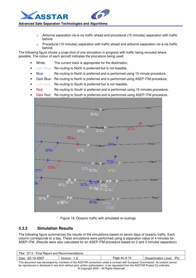
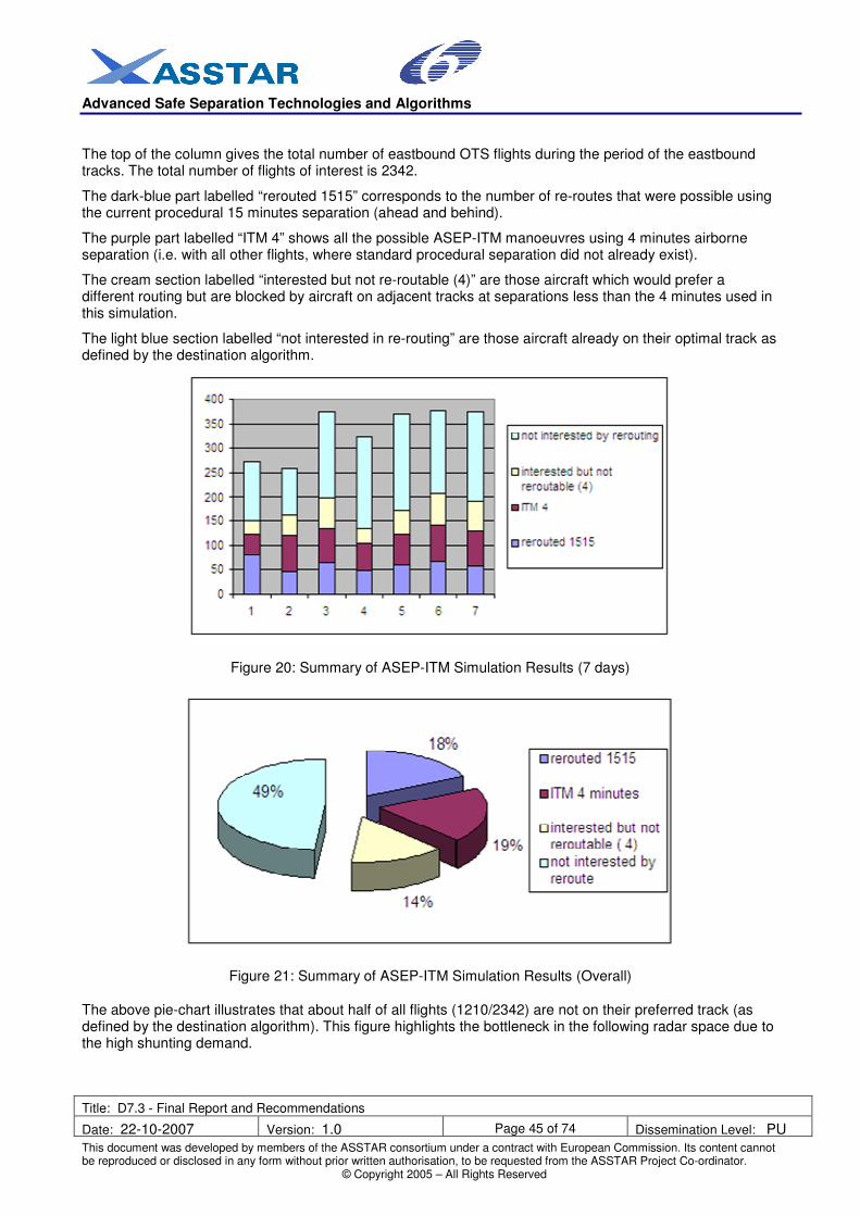
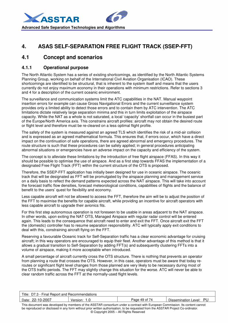
Section 4 deals with ASAS SEPARATION IN-TRAIL-MERGE. For this application, the focus was on a basic evaluation of the operational benefits, and a preliminary safety assessment.
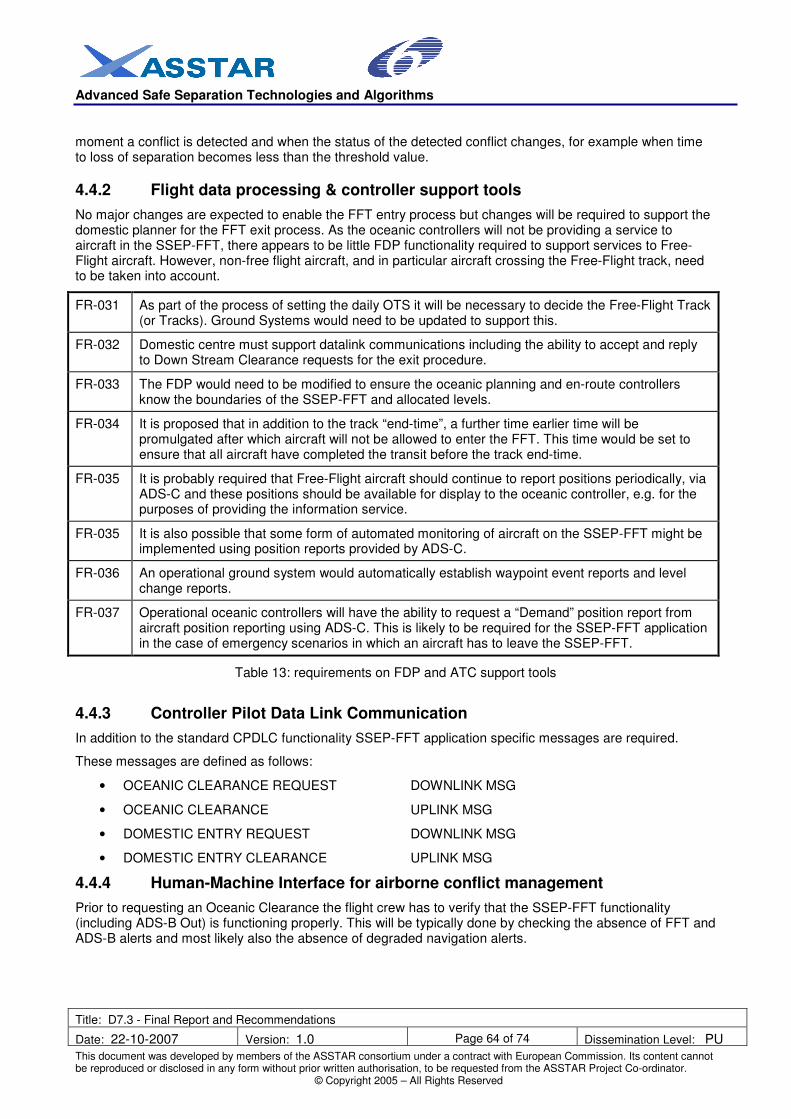
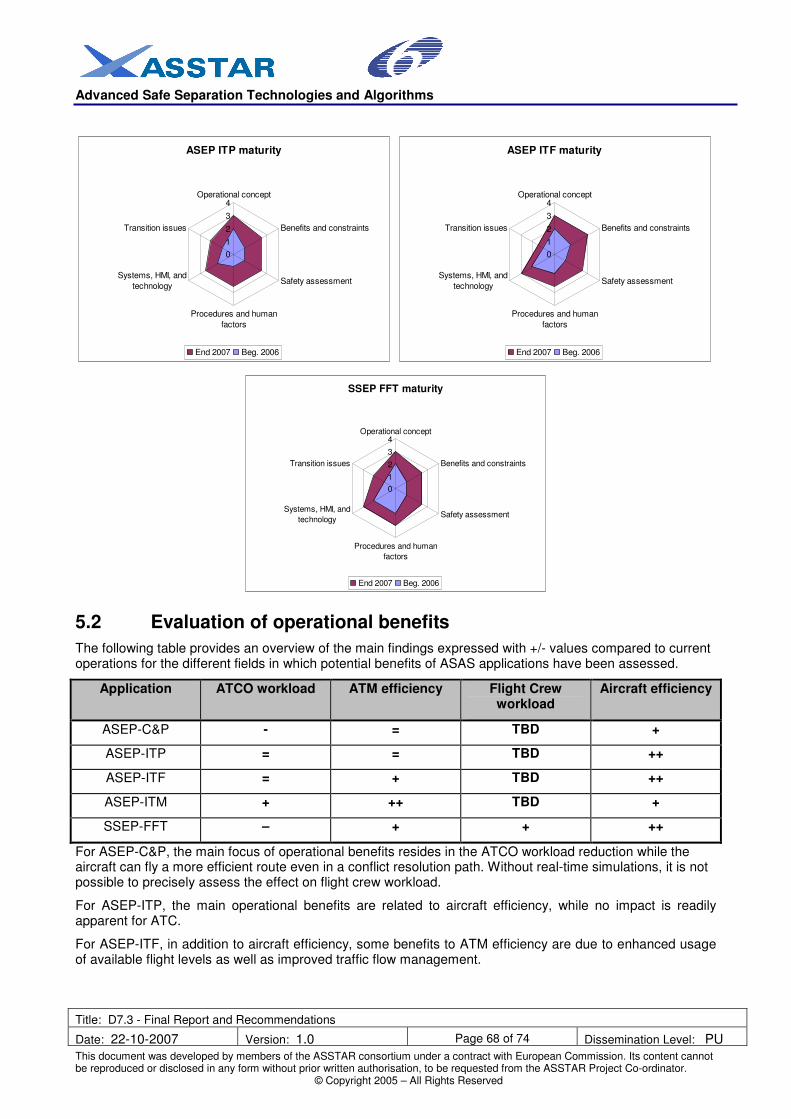
Section 5 deals with ASAS SELF-SEPARATION ON FREE FLIGHT TRACK. For this application, the focus is on the results of human-in-the-loop experiments conducted by the ASSTAR consortium.
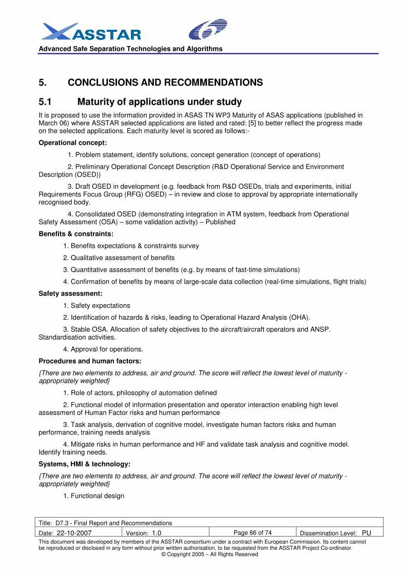
Section 6 deals with the conclusions, in terms of maturity of the applications, evaluation of operational benefits, functional requirement and implementation options, definition of operational standards, contributions for the SESAR Programme and recommendations of future studies for the European Commission.
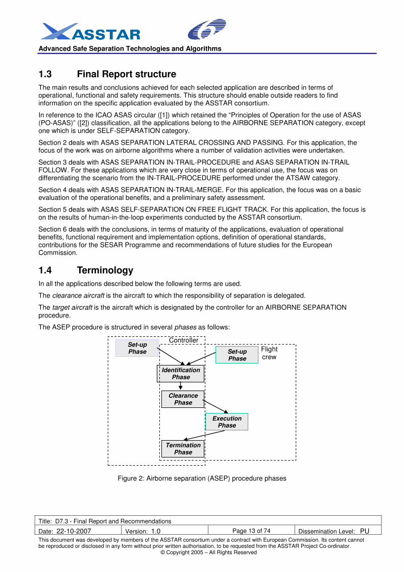
1.4 Terminology
In all the applications described below the following terms are used.
The clearance aircraft is the aircraft to which the responsibility of separation is delegated.
The target aircraft is the aircraft which is designated by the controller for an AIRBORNE SEPARATION procedure.
The ASEP procedure is structured in several phases as follows:
The purpose of the ASAS Lateral Crossing & Passing (LC&P) procedure is to provide a new set of air traffic control clearances, allowing one aircraft to cross or pass a target aircraft using ASAS. The controller delegates the responsibility for the separation from a target aircraft to the flight crew of the clearance aircraft. The controller is still responsible for separation of the clearance aircraft from all other aircraft. This responsibility is limited in time, space and scope for the duration of the ASAS LC&P procedure. Except in these limited specific circumstances where the flight crew takes responsibility for separation, ATC retains all other separation responsibility.
The separation task is delegated to the flight crew in order to support an increase in controller availability, leading to gains in efficiency, and potential capacity within the considered sectors, whilst maintaining or raising current safety levels.
The ASAS LC&P procedure is a procedure in which the qualified flight crew of suitably equipped aircraft maintain safe separation when crossing one aircraft designated by ATC, in compliance with the separation minima to be applied during the ASAS Lateral Crossing procedure, i.e. airborne separation minima.
The ASAS LC&P procedure aims to take into account, as much as possible, the current working methods and practices of flight crews and controllers in order to ensure a smooth transition. The procedure is similar to the visual separation clearance except that it is designed to be applicable both under Visual and Instrument Meteorological Conditions (VMC and IMC) and regardless of the airspace class, altitude and time of day.
Only manoeuvres that preserve lateral separation have been studied within ASAS LC&P procedure. Manoeuvres that preserve vertical separation form a separate class of applications. The main reason for that choice is that Vertical Crossing manoeuvres require a particular attention, as they may interact with vertical manoeuvres induced by advisories generated by an Airborne Collision Avoidance System (ACAS). Vertical interaction may create confusion in the flight crew regarding the manoeuvre to be performed, and thus may induce operational incompatibility and pose a safety risk. LC&P manoeuvres would not create the conditions for such confusion. In addition, LC&P manoeuvres are compatible with continuous descents or climbs, which are environmentally preferable.
1.6.2 Separation minima
The separation tasks will be based on airborne separation minima. These airborne separation minima will have to be determined at international level before being operationally implemented.
International applicability of ASAS procedures, airborne separation minima, and any amendment to flight rules would require agreement and standardisation through ICAO. The applicable airborne minima during an ASAS Lateral procedure may be less than the one applicable by ATC under specific circumstances such as separation based on single radar surveillance. However, it must be noted that the separation minima in radar airspace are already small, e.g. typically 5 NM for Europe core area, and that ATC operates with ground safety nets such as Short Term Conflict Alert (STCA). With these constraints, it is anticipated that airborne separation minima may be not very different from ground separation minima and must be compatible with ground tools.
Within the scope of the ASSTAR project, the radar separation minima applied by ATC and the airborne horizontal separation minima have the same value and in all calculations, 5 NM is taken even if locally, values such as 8NM or 10 NM can be used. Further study may indicate if these airborne separation minima values are reasonable.
Advanced Safe Separation Technologies and Algorithms
Title: D7.3 - Final Report and Recommendations
Date: 22-10-2007 Version: 1.0 Page 16 of 74 Dissemination Level: PU
The assumptions on the operational environment for ASAS LC&P procedure are summarised as follows:
• Controlled radar airspace ATS classes A, B, C, D, and E as defined in ICAO Annex 11 [7] (see section 8.2), between FL60 and FL410;
• Airspace organised through fixed route structures. However, it is anticipated that ASAS LC&P procedure may also be applicable in environments with dynamic route structures, such as free routes;
• Mix of steady, climbing and descending aircraft;
• Combination of jet and turboprop aircraft with ASAS equipment is considered;
• Lateral and longitudinal separation minima conform to ICAO PANS-ATM Doc 4444 [6]: generally not below 5NM for radar separation minima in en-route airspace and 3 NM for radar separation in the terminal area.
In addition, transition between sectors is also considered as part of the operational environment.
1.6.4 Detailed example
The ASAS LC&P procedure is an ASEP procedure which can be divided into the nominal phases described in Figure 2. .A detailed example is provided to better illustrate the typical phases of the procedure under nominal conditions. It has been presented in ASSTAR User Forum hosted by the ASAS-TN2.
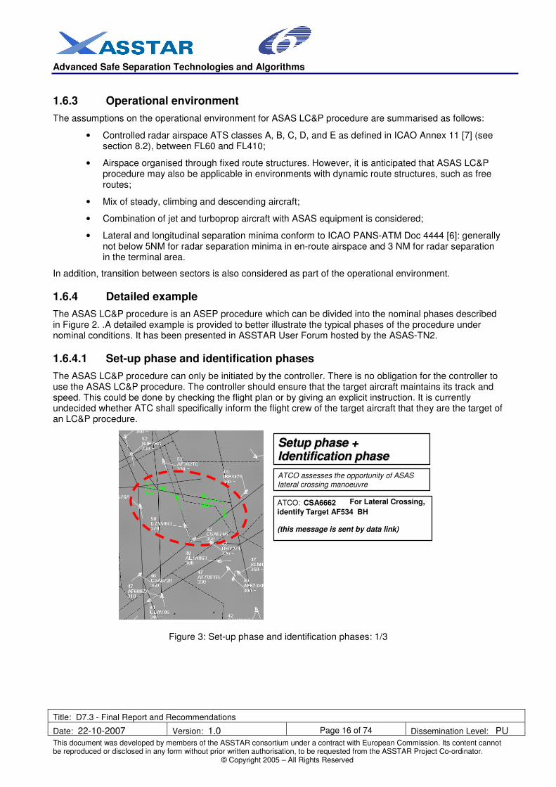
1.6.4.1 Set-up phase and identification phases
The ASAS LC&P procedure can only be initiated by the controller. There is no obligation for the controller to use the ASAS LC&P procedure. The controller should ensure that the target aircraft maintains its track and speed. This could be done by checking the flight plan or by giving an explicit instruction. It is currently undecided whether ATC shall specifically inform the flight crew of the target aircraft that they are the target of an LC&P procedure.
Figure 3: Set-up phase and identification phases: 1/3
ATCO: CSA6662 For Lateral Crossing,
identify Target AF534 BH
(this message is sent by data link)
ATCO assesses the opportunity of ASAS lateral crossing manoeuvre
S S e e t t u u p p p p h h a a s s e e + +
I I d d e e n n t t i i f f i i c c a a t t i i o o n n p p h h a a s s e e
Advanced Safe Separation Technologies and Algorithms
Title: D7.3 - Final Report and Recommendations
Date: 22-10-2007 Version: 1.0 Page 17 of 74 Dissemination Level: PU
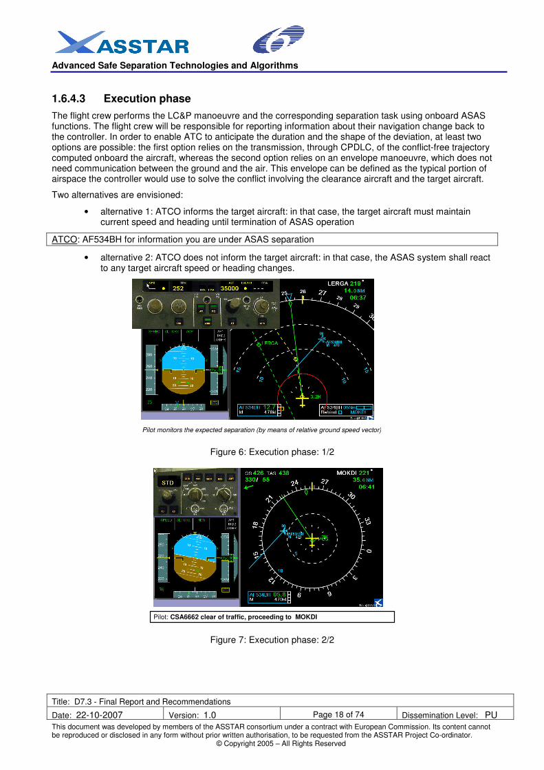
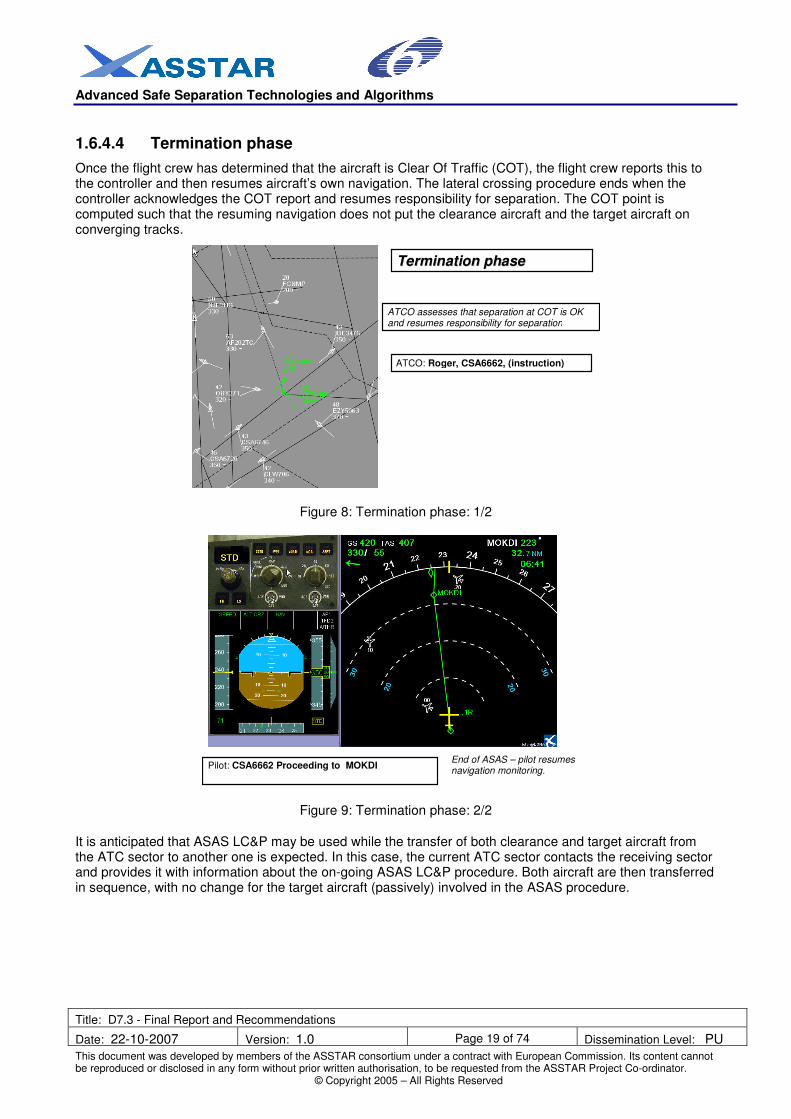
The flight crew performs the LC&P manoeuvre and the corresponding separation task using onboard ASAS functions. The flight crew will be responsible for reporting information about their navigation change back to the controller. In order to enable ATC to anticipate the duration and the shape of the deviation, at least two options are possible: the first option relies on the transmission, through CPDLC, of the conflict-free trajectory computed onboard the aircraft, whereas the second option relies on an envelope manoeuvre, which does not need communication between the ground and the air. This envelope can be defined as the typical portion of airspace the controller would use to solve the conflict involving the clearance aircraft and the target aircraft.
Two alternatives are envisioned:
• alternative 1: ATCO informs the target aircraft: in that case, the target aircraft must maintain current speed and heading until termination of ASAS operation
ATCO: AF534BH for information you are under ASAS separation
• alternative 2: ATCO does not inform the target aircraft: in that case, the ASAS system shall react to any target aircraft speed or heading changes.
Pilot monitors the expected separation (by means of relative ground speed vector)
Figure 6: Execution phase: 1/2
Pilot: CSA6662 clear of traffic, proceeding to MOKDI
Figure 7: Execution phase: 2/2
Advanced Safe Separation Technologies and Algorithms
Title: D7.3 - Final Report and Recommendations
Date: 22-10-2007 Version: 1.0 Page 19 of 74 Dissemination Level: PU
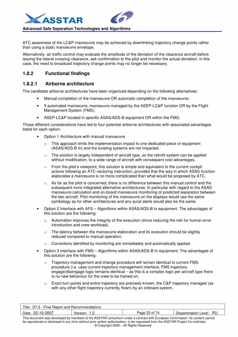
Once the flight crew has determined that the aircraft is Clear Of Traffic (COT), the flight crew reports this to the controller and then resumes aircraft’s own navigation. The lateral crossing procedure ends when the controller acknowledges the COT report and resumes responsibility for separation. The COT point is computed such that the resuming navigation does not put the clearance aircraft and the target aircraft on converging tracks.
ATCO: Roger, CSA6662, (instruction)
ATCO assesses that separation at COT is OK and resumes responsibility for separation
TTeerrmmiinnaattiioonn pphhaassee
Figure 8: Termination phase: 1/2
Pilot: CSA6662 Proceeding to MOKDI
End of ASAS – pilot resumes navigation monitoring.
Figure 9: Termination phase: 2/2
It is anticipated that ASAS LC&P may be used while the transfer of both clearance and target aircraft from the ATC sector to another one is expected. In this case, the current ATC sector contacts the receiving sector and provides it with information about the on-going ASAS LC&P procedure. Both aircraft are then transferred in sequence, with no change for the target aircraft (passively) involved in the ASAS procedure.
Advanced Safe Separation Technologies and Algorithms
Title: D7.3 - Final Report and Recommendations
Date: 22-10-2007 Version: 1.0 Page 20 of 74 Dissemination Level: PU
Equipment suppliers contribution Ease of installation and implementation, certification
Selection of Algorithm
Ease of installation and implementation, certifiable
Universities contribution Research on Algorithm Existence of scenarios
Table 1: Stakeholders requirements summary
Validation of LC&P within ASSTAR project has focused on ANSP priorities; these are capacity, efficiency of ATS, and safety, as indicated in the preceding table. ASSTAR performed research into the design and execution of ASAS LC&P manoeuvres.
1.7.2 Development of ASAS Lateral Crossing and Passing algorithms
Two geometric based ASAS LC&P manoeuvres have been assessed. The aim was to produce with the algorithm the trajectory modifications in the horizontal plane that the ATCO requests the flight crew in today’s control environment.
Both methods are based on the control of the clearance aircraft heading such that the relative velocity vector VIC is tangent to the circle bounding the protected zone of target aircraft (circle with radius S), as illustrated on the following figure: Here, VC stands for the velocity of the clearance aircraft and VI for the velocity of the target aircraft whereas h1 and h2 are the clearance aircraft headings enabling the relative velocity vector to be tangent to the circle bounding the protected zone:
Advanced Safe Separation Technologies and Algorithms
Title: D7.3 - Final Report and Recommendations
Date: 22-10-2007 Version: 1.0 Page 21 of 74 Dissemination Level: PU
Figure 10: Geometric based ASAS Lateral Crossing and Passing manoeuvres
• The first manoeuvre class which has been addressed is ‘Turning Point Manoeuvre’: the objective is to adjust the clearance aircraft velocity direction such that the relative velocity vector is tangent to the circle bounding the protected zone of the target aircraft. The turning point manoeuvre minimizes the number of resolution manoeuvre steps and may be achieved through autopilot lateral functionality.
Target aircraft Clearance aircraft
Suggested TCP Clear of
Traffic Point
Figure 11: Turning point manoeuvre
• The second manoeuvre class which has been addressed is ‘Offset Manoeuvre’: the objective is to set the time for the clearance aircraft to resume on the offset leg such that the relative velocity vector is tangent to the circle bounding the protected zone of the target aircraft. The offset manoeuvre may be compatible with Flight Management System (FMS) functionality. For the simulated offset manoeuvre, a track alteration of 30 degrees alteration has been assumed (this choice has been made in the light of current ATC practices).
Advanced Safe Separation Technologies and Algorithms
Title: D7.3 - Final Report and Recommendations
Date: 22-10-2007 Version: 1.0 Page 22 of 74 Dissemination Level: PU
These two classes of manoeuvres have been addressed through fast-time and real time simulations. This was achieved using simulated air traffic extrapolated from radar data and two interacting aircraft on relevant encounters selected from radar data.
1.8 Operational, functional and safety findings
1.8.1 Operational findings
As far as capacity of ATS is concerned, fast-time simulations have that the upper bound of the probability to use the ASAS LC&P procedure in the specific French ACC sectors which have been studied is 27%. This figure has to be mitigated by the fact that this is an upper bound computed on two sectors with a significant potential for crossing manoeuvres. Furthermore, the actual figure should be assessed by real-time simulations.
The safety aspects have been assessed through the two resolution manoeuvre classes presented in 1.7.2. The assessed airborne conflict resolution is only dependent upon ownship and target positions and velocity. In addition, only pass behind manoeuvres have been investigated since they are perceived by air traffic controllers as safer than pass in-front manoeuvres.
Assuming perfect navigation, it has been shown that 97% of the turning point manoeuvres achieved a separation between 4 and 6 NM. This figure decreases towards 93% in the case where a 1 NM navigation error was introduced. With the offset manoeuvres, 95% of the encounters are in the 4-6 NM range. This figure decreases towards 69% in case of 1 NM navigation error, although 21% of encounters achieved increased separations of between 6 and 8 NM, and are thus not a safety concern. It can be concluded that turning point manoeuvres performed better than offset manoeuvres in terms of achieving the required 5 NM separation but provide a greater maximum cross-track deviation.
As far as efficiency of ATS is concerned, navigation errors (either from ownship or from the target) and late initiation of the resolution manoeuvre significantly increase the percentage of unresolved conflicts by the airborne system. The former points out the close link which should exist between a future airborne separation standard and required navigation performance, whereas the latter is linked with the conditions of applicability of the LC&P manoeuvre. Indeed, the ATCO should avoid the late issuance of clearance:
• if not, the radius of turn may be insufficient to enable the clearance aircraft to correctly perform the LC&P manoeuvre;
• in addition, a required range envelope should be integrated within the applicability conditions.
Advanced Safe Separation Technologies and Algorithms
Title: D7.3 - Final Report and Recommendations
Date: 22-10-2007 Version: 1.0 Page 23 of 74 Dissemination Level: PU
ATC awareness of the LC&P manoeuvre may be achieved by downlinking trajectory change points rather than using a static manoeuvre envelope.
Alternatively, air traffic control may evaluate the amplitude of the deviation of the clearance aircraft before issuing the lateral crossing clearance, ask confirmation to the pilot and monitor the actual deviation: in this case, the need to broadcast trajectory change points may no longer be necessary.
1.8.2 Functional findings
1.8.2.1 Airborne architecture
The candidate airborne architectures have been organized depending on the following alternatives:
• Manual completion of the manoeuvre OR automatic completion of the manoeuvre;
• If automated manoeuvre, manoeuvre managed by the ASEP-LC&P function OR by the Flight Management System (FMS);
• ASEP-LC&P located in specific ASAS/ADS-B equipment OR within the FMS;
Those different considerations have led to four potential airborne architectures with associated advantages listed for each option:
• Option 1 Architecture with manual manoeuvre
o This approach limits the implementation impact to one dedicated piece of equipment (ASAS/ADS-B In) and the existing systems are not impacted.
o The solution is largely independent of aircraft type, so the retrofit system can be applied without modification, to a wide range of aircraft with consequent cost advantages.
o From the pilot’s viewpoint, this solution is simple and equivalent to the current cockpit actions following an ATC vectoring instruction, provided that the way in which ASAS function elaborates a manoeuvre is no more complicated than what would be proposed by ATC.
o As far as the pilot is concerned, there is no difference between this manual control and the subsequent more integrated alternative architectures. In particular with regard to the ASAS manoeuvre calculation and on-board manoeuvre monitoring of predicted separation between the two aircraft. Pilot monitoring of the manoeuvre on the displays would use the same symbology as for other architectures and any aural alerts would also be the same.
• Option 2 Interface with AFS – Algorithms within ASAS/ADS-B In equipment. The advantages of this solution are the following:
o Automation improves the integrity of the execution (since reducing the risk for human error introduction and crew workload).
o The latency between the manoeuvre elaboration and its execution should be slightly reduced compared to manual operation.
o Corrections identified by monitoring are immediately and automatically applied.
• Option 3 Interface with FMS – Algorithms within ASAS/ADS-B In equipment. The advantages of this solution are the following:
o Trajectory management and change procedure will remain identical to current FMS procedure (i.e. uses current trajectory management interface, FMS trajectory engage/disengage logic remains identical – as this is a complex logic per aircraft type there is no new behaviour for the crew to be trained on.
o Exact turn points and entire trajectory are precisely known, the C&P trajectory managed (as with any other flight trajectory currently flown) by an onboard system.
Advanced Safe Separation Technologies and Algorithms
Title: D7.3 - Final Report and Recommendations
Date: 22-10-2007 Version: 1.0 Page 24 of 74 Dissemination Level: PU
o Exact ASAS manoeuvre information to ground ATC is possible via datalink (FMS already has a datalink interface).
• Option 4 Interface with FMS – Algorithms within FMS equipment. The advantages of this solution are the following:
o Transmission of information requires a simple broadcast link (no messaging protocol required); spare I/O data ports readily available for such acquisition.
o Trajectory computed and available for crew validation before FMS insertion.
o Trajectory management and change procedure will remain identical to current FMS procedure (i.e. uses current trajectory management interface for the trajectory change).; FMS trajectory engage/disengage logic remains identical – as this is a complex logic per aircraft type there is not another new behaviour for the crew to be trained on.
o Exact turn points and entire ASAS trajectory is precisely known, the ASAS trajectory is managed (as any other flight trajectory currently flown) by an onboard system, and the trajectory transitions at waypoints (bank angle, turn radius, …) is managed by the FMS according to validated behaviour.
o For conflict resolutions if a vertical change is also occurring, FMS performance computations are likely to be required. Certain flight domains also impose manoeuvring restrictions – such manoeuvring limitation is already managed in the FMS.
o Exact ASAS manoeuvre information to ground ATC possible via datalink (FMS already has a datalink interface).
o System benefits from the dual FMS architecture present on majority of air-transport aircraft such improving availability.
o All change is isolated in a single location; the location is best suited where all the flight data and trajectory information is available.
o Alerts and Information Messages management is done through existing FMS management of display information.
1.8.2.2 Ground architecture
As the ASEP-LC&P application is performed with complete reliance on the aircraft, a key objective in the ground based radar architecture is to minimize changes directly related to the ASEP-LC&P application. Considering the requirements identified along the successive steps of the procedure, including safety requirements, the following evolution should be implemented:
• Before delegation:
o Presentation of the aircraft ASAS capability;
o Assistance tool for supporting identification of pairs of candidate aircraft for the ASEP-LC&P manoeuvre. The ATCO may use specific assistance tools (e.g. trajectory conflict prediction tools) in the planning or anticipation phase but these are not considered mandatory, in the baseline ATC radar system, as a basis for the ASAS C&P application. They could be available, depending on ground control centre implementation, and if available would provide additional assistance to the ATCO in decisions prior to the ASAS manoeuvre.
• During delegation:
o Specific identification of aircraft (clearance : target) under the ASEP-LC&P manoeuvre;
o LC&P manoeuvre elaborated by the clearance aircraft (if available but only a while after clearance delivery), for helping to monitor separation with surrounding traffic. The ATCO must keep in mind this information as the ASAS resolution can vary in time due to necessary adjustment during ASAS clearance execution.
Advanced Safe Separation Technologies and Algorithms
Title: D7.3 - Final Report and Recommendations
Date: 22-10-2007 Version: 1.0 Page 25 of 74 Dissemination Level: PU
ESARR4 requires a quantitative risk assessment whenever the ATM system is changed. The relevant target is 1.55*10
-8 accidents per flight hour with a direct ATM contribution, corresponding to a maximal allowable
accident rate of 2.31*10-8
per flight for an average flight time of 1.5 hours. As far as ASEP-LC&P manoeuvre is concerned, a systematic and structured approach to risk assessment and mitigation, including hazard identification, has been conducted. The following quantitative safety objectives have been derived:
• The likelihood that ASAS system logic generates an erroneous ASEP-LC&P manoeuvre shall be less than EXTREMELY REMOTE i.e. less than 9.5*10
-8 occurrences per flight hour.
• The likelihood of wrong execution of ASEP-LC&P manoeuvre by the pilot shall be less than REMOTE i.e. less than 1.4*10
-6 occurrences per flight hour.
• The likelihood of total/partial loss of ASAS information on board shall be less than EXTREMELY REMOTE i.e. less than 9.5*10
-8 occurrences per flight hour.
• The likelihood of unexpected target behaviour shall be less than REMOTE i.e. less than 1.4*10-6
occurrences per flight hour.
• The likelihood of airborne premature/late determination of Clear Of Traffic shall be less than EXTREMELY REMOTE i.e. less than 9.5*10
-8 occurrences per flight hour.
1.9 ASEP-LC&P summary
The ASEP-LC&P application has been developed in response to the operational need to authorise aircraft to perform lateral crossing whilst maintaining separation, as an extrapolation of the existing visual separation clearance. The work package developed an operational concept supported by the description of the operational scenarios.
A test bed facility has been developed supporting numerous simulations and evaluations, including the development and the validation of conflict resolution algorithms suitable for airborne equipment. Although no real-time simulations were conducted, several illustrations of the procedure based on operational examples were performed. As a consequence, the systems HMI and technology aspects were progressed satisfactorily in particular with several sound proposals for airborne architecture and system requirements.
The operational benefits are anticipated in the area of ATCO workload reduction and aircraft efficiency. According to the typical route structure of a given sector, the frequency of occurrence, i.e., the opportunity for the ATCO to perform an ASEP-LC&P can be quite high. Figures up to 26% are derived from the scenario evaluated in the project in a sector quite suitable for lateral crossing manoeuvres.
The safety assessment was conducted identifying and quantifying the critical hazards that might occur during a LC&P manoeuvre, while enabling the development of an operational procedure including clarification of the roles of all actors.
The main functional requirements are derived from the dimensional hazard which is the collision risk. It is recalled that ATC monitoring loop in current system contributes to high integrity, by enabling a detection of discrepancies and blunders. Airborne separation principles places extremely high confidence on navigation position integrity and continuity; as a consequence, stringent performance levels can be expected on the airborne systems, even if the flight deck is monitoring the situation. In addition, the requirements are placed on both clearance aircraft and target aircraft data. Finally, datalink i.e., CPDLC is recommended for this operational procedure.
Advanced Safe Separation Technologies and Algorithms
Title: D7.3 - Final Report and Recommendations
Date: 22-10-2007 Version: 1.0 Page 26 of 74 Dissemination Level: PU
2. ASAS SEPARATION IN-TRAIL PROCEDURE AND IN-TRAIL FOLLOW
2.1 Concept and scenarios
This section contains an overview of both Airborne Separation In-Trail Procedure (ASEP-ITP) and In-Trail Follow (ASEP-ITF) applications in terms of operational concept, scenarios, functional, procedural and safety requirements. Due to their commonalities, the two applications have been grouped together.
2.1.1 Operational environment
The areas considered for these applications are oceanic airspace where radar surveillance is unavailable and where procedural control is exercised, e.g. the North Atlantic (NAT) and Pacific Airspace. Flight time from entry to exit is typically several hours. The applications are developed for Class A airspace, in which Instrument Flight Rules (IFR) apply at all times. Within the relevant part of the airspace, tracks are defined in a possibly dynamic way.
The North-Atlantic Organised Track System (OTS) is set up on a diurnal basis to facilitate a high throughput of traffic by ensuring separation for the entire oceanic crossing. Each core OTS is comprised of a set, typically 4 to 7, of parallel or nearly parallel tracks, positioned in the light of the prevailing winds (jet streams in particular) to suit the traffic flying between Europe and North America.
The current separation minima (i.e. without implementation of any ASAS application) prescribed by ICAO are contained in the ICAO PANS-ATM (DOC4444) [6] and the ICAO Regional Supplementary Procedures (DOC7030) [8]. Within a track system in an Oceanic airspace, separation can be maintained with respect to three dimensions:
• Vertical. The separation minima are 1000 feet in Reduced Vertical Separation Minima (RVSM) airspace and 2000 feet in non-RVSM airspace. ATC assigns aircraft to Flight Levels (FL) and aircrew and aircraft maintain height.
• Lateral. The distance between tracks depends on the airspace. In the NAT region, the typical spacing between closest tracks is 60 NM (or 1 degree of latitude or change latitude by no more than 2 degrees over a longitude of 10 degrees [8]). In the Composite route structure of the Pacific ICAO Region, the applicable lateral separation minimum is 50 NM
1. ATC assigns aircraft
to tracks and aircrew and aircraft maintain track.
• Longitudinal separation between subsequent aircraft following the same track is provided by the Mach number technique being applied, ensuring that aircraft remain separated in time
2. Typical
separation minima are 10 minutes in the NAT region and 15 minutes in the Pacific ICAO Region. The Mach number technique is based on the calculation of arrival time at certain points by means of Mach number, on the reported Estimated Time of Arrivals (ETA) at common waypoints and on simple rules for required compensation if a second aircraft is overtaking the first aircraft.
2.2 ASAS Separation In-Trail Procedure
2.2.1 Outline of ASEP-ITP procedure
The ASEP-ITP application has been designed for use in oceanic and other non-radar airspace, although the airspace must be controlled. It is intended as a means of improving the vertical flexibility, allowing aircraft to climb where current procedural separation standards would not allow it.
1 The lateral separation minimum in the Rectangular Route Structure of the Pacific ICAO Region ranges from
20 NM for RNP4 aircraft with direct voice or CPDLC or ADS-C communication with ATC to 100 NM. 2 In the Pacific ICAO Region longitudinal separation can also be RNP based (with or without ADS-C), in
which case spacious separation minima apply, from 30 NM for RNP 4 and 14 minutes updates, and higher.
Advanced Safe Separation Technologies and Algorithms
Title: D7.3 - Final Report and Recommendations
Date: 22-10-2007 Version: 1.0 Page 27 of 74 Dissemination Level: PU
ASEP-ITP enables climbs or descents through the FL of one or two target aircraft at an intervening same direction FL. An intervening, same-direction FL is 1,000 feet above (or below) the FL from which the manoeuvre is initiated in the NAT. The primary benefit expected from ASEP-ITP is the fuel-saving achieved by enabling aircraft to fly more often at their optimum fuel efficient level. Secondary benefits include safety and passenger comfort from an improved ability to avoid turbulent FL.
The proposed ASEP-ITP application is analogous to the ATSA-ITP application but would transfer responsibility for separation between the clearance aircraft and the target aircraft from the controller to the flight crew of the manoeuvring aircraft for the period of the manoeuvre. Responsibility for separation is resumed by the controller when the flight crew report that the manoeuvre is complete.
The ASEP-ITP application will enable an aircraft to climb or descend in situations where current oceanic separation standards would prevent the manoeuvre. It may also be of use in a greater range of situations than the proposed ATSA-ITP procedure, i.e. the initial conditions for ASEP-ITP may be less demanding.
However the avionics integrity requirements for ASEP-ITP are likely to be more demanding and the changes to current roles and responsibilities would be more extensive. ASEP-ITP would require the crew to use airborne surveillance information provided on the flight deck to identify the potential opportunity to use ASEP-ITP and to maintain separation from the target aircraft during the manoeuvre. ATC would still be required to check that separation minima will be met with all other aircraft, and to clear the ASEP-ITP climb or descent.
It is expected that ASEP-ITP could be implemented without changes to the current airspace design (e.g. track structures, Flight Level Orientation Scheme (FLOS)) for Oceanic Airspace (procedural control).
To cover different initial geometries, six variations of the ASEP-ITP manoeuvre are envisaged:
1. A Following Climb.
2. A Following Descent.
3. A Leading Climb.
4. A Leading Descent.
5. A Combined Leading-Following Climb.
6. A Combined Leading-Following Descent.
2.2.2 Example of ASEP-ITP following climb scenario
Taking an example for ASEP-ITP use in an Oceanic Airspace (procedural control), suppose that an aircraft is established on an oceanic track at a FL from which it would like to climb (it could also apply for a descent).
ITP Criteria
FL340
FL350
FL360
Other aircraft Other aircraft
Standard Longitudinal
Separation Requirement
Clearance Aircraft
Standard Longitudinal
Separation Requirement
Other aircraft Target Aircraft
Figure 13: Proposed ASEP-ITP scenario
Setup phase
The flight crew of the clearance aircraft notices a blocking aircraft in front at the level above which prevents a standard climb to that level or levels further above. This aircraft will become the target aircraft in the
Advanced Safe Separation Technologies and Algorithms
Title: D7.3 - Final Report and Recommendations
Date: 22-10-2007 Version: 1.0 Page 28 of 74 Dissemination Level: PU
procedure. The flight crew also notices that there is a gap two levels above where standard separation is possible.
Identification phase
If the clearance aircraft is equipped for ASEP-ITP and the target aircraft has at least qualified ADS-B OUT capability, then an ASEP-ITP based climb might be considered. Using ASEP-ITP the clearance aircraft would be able to climb two levels, in this example to reach FL360.
Note: the qualification for ADS-B out capability for the target aircraft could be different between ASEP-ITP and ATSA-ITP. For instance, dual links could be required.
An ASEP-ITP climb will only be permitted if the spacing and speed differential with the target aircraft meet initial conditions which are defined in the section 2.2.3.
Clearance phase
If the flight crew thinks that the ASEP-ITP climb conditions are met then he may request an ASEP-ITP climb, stating the identity and range of the proposed target aircraft. In approving the request the controller must check that the identity and range of the target aircraft stated in the request are consistent with ground held information. The controller must also check that there are no other aircraft, perhaps not ADS-B equipped and hence not known to the clearance aircraft, to prevent the ASEP-ITP climb.
Execution phase
Once approved, the flight crew initiates the climb, maintaining a minimum rate of at least 300 fpm. The crew now has responsibility for separation from the target aircraft and is required to monitor the position of the target aircraft on the CDTI during the climb.
Termination phase
The flight crew reports once established on the new FL and the ASEP-ITP procedure is terminated.
2.2.3 Applicability Conditions for ASEP-ITP
Therefore, In-Trail Procedure (ITP) makes climbs and descents through otherwise blocked FL possible, providing a safe and practical method for Air Navigation Service Providers to approve, and flight crews to conduct, such operations.
It is suggested an airborne separation minima of 10 NM for aircraft on the same track. The value of 10 NM is proposed as an extrapolation of a similar procedure referenced in ICAO PANS-ATM based on DME. The following applicability conditions are described for “Following Climb” case but equivalent conditions can be drawn by analogy for the other cases.
ASEP-ITP qualification:
• The aircraft wanting to perform the ASEP-ITP manoeuvre has “ASEP-ITP Equipment”, providing the flight crew with the flight ID of the target aircraft, the range to the target aircraft, and speed guidance to assist in maintaining the spacing.
• The airline Operational Specifications of the clearance aircraft permit the ASEP-ITP manoeuvre.
• The flight crew of the clearance aircraft is properly qualified for ASEP-ITP.
ASEP-ITP Preconditions:
• Only one intervening FL is allowed between the current level and the level to be requested.
• The maximum FL change requested for an ASEP-ITP climb is 4,000 feet. (2,000 feet for Oceanic Airspace (procedural control) Airspace).
• The Requested Flight Level (RFL) shall be one same direction FL above (for a climb) the intervening FL.
• Clearance aircraft must be able to maintain assigned Mach number throughout the procedure.
Advanced Safe Separation Technologies and Algorithms
Title: D7.3 - Final Report and Recommendations
Date: 22-10-2007 Version: 1.0 Page 29 of 74 Dissemination Level: PU
• Clearance aircraft position data must meet the accuracy requirement for ASEP-ITP.
ASEP-ITP Initiation Criteria:
• Clearance aircraft is following the same Oceanic Airspace (procedural control) Track as the target aircraft. (Oceanic Airspace (procedural control) specific).
• Target aircraft has qualified ADS-B.
• Initial conditions, Option A:
o ASEP-ITP range and ground speed differential criteria are met with the target aircraft i.e.:
� Initiation range of no less than 10 NM and a positive ground speed differential of no more than 20 kt or
� Initiation range of no less than 15 NM and a positive ground speed differential of no more than 30 kts.
• Initial conditions, Option B (alternative proposal)
o Range between the clearance aircraft and the target aircraft is at least 10NM and the flight crew of the clearance aircraft assesses the ground speed differential to be such that this minimum separation can be maintained throughout the manoeuvre.
This implies that the clearance aircraft would need automation in particular for the maintenance of the separation throughout the manoeuvre.
• Clearance aircraft performance will enable a rate of climb or descent of at least 300 fpm at the assigned Mach number to the RFL.
ASEP-ITP Request:
• If the qualifications, preconditions, and criteria are met, the crew requests the ASEP-ITP manoeuvre, using the required ASEP-ITP phraseology and providing the controller with the flight ID and range of the target aircraft.
2.2.4 Roles and Responsibilities during the ASEP-ITP procedure
• Flight crew of the clearance aircraft determines if a FL change is desired.
• Flight crew determines that at least one target aircraft is present.
• Flight crew determines that the own aircraft meets the minimum performance required for the RFL change, i.e., a minimum 300 fpm climb or descent at the assigned Mach number.
• Flight crew decides to use ASEP-ITP, based on an advisory provided by the airborne system.
• Flight crew determines if the ASEP-ITP criteria are met based on information provided by the airborne system.
• If the ASEP-ITP criteria are met, the flight crew requests an ASEP-ITP climb/descent, and provides ATC with the flight ID(s) of and Range(s) to the target aircraft, using the prescribed phraseology.
• ATC determines if the standard longitudinal separation minimum will be met at the RFL and at all FLs between the aircraft’s initial FL and RFL for other aircraft. ATC also determines if the target aircraft has (have) made a request to reduce speed or change FL, or are about to reach a point at which a significant change of track will occur. If the separation criteria are met at the RFL with other aircraft, and the target aircraft is maintaining speed, FL, and track, ATC may issue the ASEP-ITP FL change clearance. The controller uses gross proximate position (from the Range provided by the flight crew) to validate the flight ID of the target aircraft.
• If the request is granted and the FL change clearance received, the flight crew reconfirms that the target aircraft ADS-B remains qualified and the criteria for the ASEP-ITP manoeuvre
Advanced Safe Separation Technologies and Algorithms
Title: D7.3 - Final Report and Recommendations
Date: 22-10-2007 Version: 1.0 Page 30 of 74 Dissemination Level: PU
(minimum range and maximum Positive Ground Speed Differential) are still met, and then initiates the FL change to the assigned FL. The crew reports leaving the initial FL.
• Flight crew assumes responsibility for maintaining separation from the target aircraft during the manoeuvre and monitors the separation throughout.
• Flight crew reports established at the new FL.
• ATCO resumes responsibility for all separations.
2.3 ASAS Separation In-Trail Follow
2.3.1 Outline of ASEP-ITF procedure
The Mediterranean Free Flight (MFF) Operational Concept ( [4]) forms the basis for defining the In-Trail Follow Application. A3 ‘MFF Airborne Spacing – Sequencing and Merging’ has been adapted to Airborne Separation on Oceanic Tracks in the North Atlantic environment.
The ASEP-ITF application is designed for use en-route in an Oceanic environment. The objective is to reduce controller workload and to increase capacity and flight efficiency. This will be achieved by redistributing tasks and separation responsibility related to the in-trail following of traffic between the controllers and the aircrews.
Both oceanic and domestic controllers will be provided with new ATC procedures directing, for example, the aircrews to establish at the oceanic entry point and to maintain a given time or distance from a designated aircraft. The aircrews will perform these new tasks using new aircraft functions (e.g. airborne surveillance, display of traffic information, spacing functions). The use of ITF procedures will replace most of the controller’s use of the sliding Mach technique to separate traffic in the NAT Organised Track System, or more general in NAT airspace for traffic flying the same route. Nevertheless, in the first place the OTS is considered due to its relatively high traffic density.
Expected benefits include reduced controller workload by the reorganisation and the streamlining of tasks. It is also expected to assure more regular and reliable airborne separation, with subsequent separation values below the normal procedural separation minima. This is expected to lead to greater capacity, as well as to more efficient operations. On the airborne side, these procedures will lead to the use of more efficient flight profiles, allowing potential savings in fuel.
Prior to entering the Oceanic Track System the domestic controller builds a time-based sequence of aircraft along the routes towards the entry points of the Oceanic tracks considering the ASEP-ITF application in Oceanic Airspace.
The responsibility for assuring separation will be transferred from the controller to the flight crew during the ASEP-ITF application. Two use cases are considered.
2.3.2 Outline of Procedure – Use Case (i)
ASEP-ITF is intended as a means of improving the vertical flexibility, allowing aircraft to climb where current procedural separation standards would not allow it. The application would transfer responsibility for separation between the clearance aircraft and the target aircraft from the controller to the flight crew of the clearance aircraft for the period of the manoeuvre. It will enable an aircraft to climb or descend in situations where current oceanic separation standards and ASEP-ITP procedures would prevent the manoeuvre. The avionics accuracy and integrity requirements are likely to be rather demanding and the changes to current roles and responsibilities would be significant. ASEP-ITF would require the crew to use airborne surveillance information provided on the flight deck to identify the potential opportunity to use ASEP-ITF and to maintain separation from the target aircraft during the manoeuvre. The controller would still be required to check that standard separation minima will be met with all other aircraft, and to clear the ASEP-ITF climb or descent.
ASEP-ITF enables climbs or descents to the FL of a target aircraft at a same direction FL.
Advanced Safe Separation Technologies and Algorithms
Title: D7.3 - Final Report and Recommendations
Date: 22-10-2007 Version: 1.0 Page 31 of 74 Dissemination Level: PU
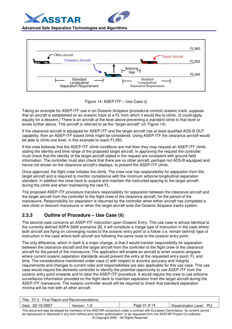
Taking an example for ASEP-ITF use in an Oceanic Airspace (procedural control) oceanic track, suppose that an aircraft is established on an oceanic track at a FL from which it would like to climb. (It could apply equally for a descent.) There is an aircraft at the level above preventing a standard climb to that level or levels further above. This aircraft is referred to as the “target aircraft” (cf. Figure 14).
If the clearance aircraft is equipped for ASEP-ITF and the target aircraft has at least qualified ADS-B OUT capability, then an ASEP-ITF based climb might be considered. Using ASEP-ITF the clearance aircraft would be able to climb one level, in this example to reach FL350.
If the crew believes that the ASEP-ITF climb conditions are met then they may request an ASEP-ITF climb, stating the identity and time range of the proposed target aircraft. In approving the request the controller must check that the identity of the target aircraft stated in the request are consistent with ground held information. The controller must also check that there are no other aircraft, perhaps not ADS-B equipped and hence not shown on the clearance aircraft’s displays, to prevent the ASEP-ITF climb.
Once approved, the flight crew initiates the climb. The crew now has responsibility for separation from the target aircraft and is required to monitor compliance with the minimum airborne longitudinal separation standard. In addition the crew have to acquire and maintain the instructed spacing to the target aircraft during the climb and when maintaining the new FL.
The proposed ASEP-ITF procedure transfers responsibility for separation between the clearance aircraft and the target aircraft from the controller to the flight crew of the clearance aircraft, for the period of the manoeuvre. Responsibility for separation is resumed by the controller when either aircraft has completed a new climb or descent manoeuvre or when the target aircraft exits the Oceanic Airspace tracks system.
2.3.3 Outline of Procedure – Use Case (ii)
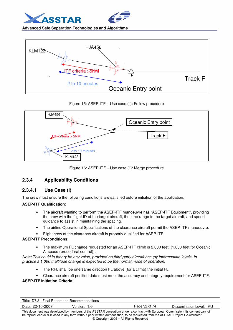
The second case concerns an ASEP-ITF instruction upon Oceanic Entry. This use case is almost identical to the currently defined ASPA-S&M scenarios [9], it will constitute a merge type of instruction in the case where both aircraft are flying on converging routes to the oceanic entry point or a follow (i.e. remain behind) type of instruction in the case where both aircraft are following the same route to the oceanic entry point.
The only difference, which in itself is a major change, is that it would transfer responsibility for separation between the clearance aircraft and the target aircraft from the controller to the flight crew of the clearance aircraft for the period of the manoeuvre. The application will enable an aircraft to enter oceanic airspace where current oceanic separation standards would prevent the entry at the requested entry point, FL and time. The considerations mentioned under case (i) with respect to avionics accuracy and integrity requirements and changes to current roles and responsibilities are also applicable for this use case. This use case would require the domestic controller to identify the potential opportunity to use ASEP-ITF from the oceanic entry point onwards and to clear the ASEP-ITF procedure. It would require the crew to use airborne surveillance information provided on the flight deck to maintain separation from the target aircraft during the ASEP-ITF manoeuvre. The oceanic controller would still be required to check that standard separation minima will be met with all other aircraft.
Advanced Safe Separation Technologies and Algorithms
Title: D7.3 - Final Report and Recommendations
Date: 22-10-2007 Version: 1.0 Page 32 of 74 Dissemination Level: PU
Figure 15: ASEP-ITF – Use case (ii): Follow procedure
Figure 16: ASEP-ITF – Use case (ii): Merge procedure
2.3.4 Applicability Conditions
2.3.4.1 Use Case (i)
The crew must ensure the following conditions are satisfied before initiation of the application:
ASEP-ITF Qualification:
• The aircraft wanting to perform the ASEP-ITF manoeuvre has “ASEP-ITF Equipment”, providing the crew with the flight ID of the target aircraft, the time range to the target aircraft, and speed guidance to assist in maintaining the spacing.
• The airline Operational Specifications of the clearance aircraft permit the ASEP-ITF manoeuvre.
• Flight crew of the clearance aircraft is properly qualified for ASEP-ITF.
ASEP-ITF Preconditions:
• The maximum FL change requested for an ASEP-ITF climb is 2,000 feet. (1,000 feet for Oceanic Airspace (procedural control)).
Note: This could in theory be any value, provided no third party aircraft occupy intermediate levels. In practice a 1,000 ft altitude change is expected to be the normal mode of operation.
• The RFL shall be one same direction FL above (for a climb) the initial FL.
• Clearance aircraft position data must meet the accuracy and integrity requirement for ASEP-ITF.
ASEP-ITF Initiation Criteria:
Track F
HJA456
KLM123
Oceanic Entry point
ITF criteria > 5NM
2 to 10 minutes
Advanced Safe Separation Technologies and Algorithms
Title: D7.3 - Final Report and Recommendations
Date: 22-10-2007 Version: 1.0 Page 33 of 74 Dissemination Level: PU
• The ASEP-ITF Aircraft is following the same Oceanic Airspace (procedural control) Track as the target aircraft. (Oceanic Airspace (procedural control) specific).
• Target aircraft has qualified ADS-B OUT for ASEP-ITF.
• Initial conditions:
o The ASEP-ITF criteria are met with the target aircraft i.e.:
� Target aircraft is flying ahead of clearance aircraft.
� Time spacing of no less than 2 minutes3. The instructed time spacing shall be such
that the minimum airborne separation shall always be larger than 5 NM4. Given a
minimum groundspeed of 240 kts (4 NM/min) the 5 NM translates into 1 minute and 15 seconds. Assuming a 30 second spacing tolerance, the initial minimum allowable spacing is thus set to 2 minutes.
� ASEP-ITF aircraft must be able to maintain Mach numbers between and including the assigned Mach numbers of the clearance aircraft and of the target aircraft throughout the procedure. (A simplification could be that the ASEP-ITF aircraft must be able to maintain the assigned Mach number with a tolerance of plus zero and minus Mach 0.03 (as a basis for discussion).
The transfer of separation responsibility to the flight crew in fact in itself implies that speed authority is delegated for ASEP-ITF, but within a predefined tolerance.
ASEP-ITF Request:
• If the qualifications, preconditions, and criteria are met, the crew requests the ASEP-ITF manoeuvre, using the required ASEP-ITF phraseology and providing the controller with the flight ID and time range of the target aircraft.
2.3.4.2 Use Case (ii)
The main trigger is that oceanic entry requests are received that do not comply with standard longitudinal separation criteria. The oceanic planning controller must ensure that the following conditions are satisfied before issuing an oceanic clearance based on the subsequent use of the ASEP-ITF application:
• Compatible positions of aircraft (altitude and relative position);
• Compatible routes (identical routes or routes merging at the oceanic entry point);
• Compatible performance of aircraft, particularly speed;
• Appropriate ASAS capability of aircraft;
• The spacing value given to the instructed aircraft must be compatible with the predicted spacing at the oceanic entry point. Instructed time spacing shall be no less than 2 minutes.
After the crew receives an identification message for airborne separation they have to make sure that the following conditions are continuously satisfied:
• Clearance aircraft ASAS equipment is adequately functioning for ASEP-ITF;
• Clearance aircraft position data must meet the accuracy and integrity requirement for ASEP-ITF;
• Target aircraft has qualified ADS-B OUT for ASEP-ITF.
3 It has been decided to select time as primary spacing parameter because oceanic control is currently time-based and more important
time-based spacing is more robust in changing wind conditions (e.g. flying into a jet-stream). 4 A value of 5 NM has been chosen to be compatible with ASEP-ITP and SSEP-FFT. When GNSS is used as primary means of
navigation, as is the case for current flight operations, initial studies indicate that -at least for the positioning accuracy parameter- an airborne horizontal separation minimum of 5 NM seems feasible.
Advanced Safe Separation Technologies and Algorithms
Title: D7.3 - Final Report and Recommendations
Date: 22-10-2007 Version: 1.0 Page 34 of 74 Dissemination Level: PU
• Flight crew of the clearance aircraft determines if a FL change is desired.
• Flight crew determines that one target aircraft is present.
• Dlight crew determines that their aircraft meets the minimum performance required for the In-Trail Follow, i.e., the aircraft is able to fly any speed between the assigned Mach numbers of clearance aircraft and target aircraft.
• Flight crew determines if the ASEP-ITF criteria are met based on information provided by the ASAS equipment.
• If the ASEP-ITF criteria are met, the flight crew requests an ASEP-ITF climb/descent and provides ATC with the Flight ID of and Time Range to the target aircraft.,
• ATC determines if the standard longitudinal separation minimum will be met at the RFL for third party aircraft and, if applicable, at all FLs between the aircraft’s initial FL and RFL. ATC also determines if the target aircraft has made a request to reduce speed or change FL. If the separation criteria are met at the RFL with third party aircraft and the target aircraft is maintaining speed and FL, ATC may issue the ASEP-ITF FL change clearance. The controller uses the reported time range and assigned Mach numbers of both aircraft to establish a desired spacing value or spacing interval.
• Flight crew assumes responsibility for acquiring and maintaining spacing from target aircraft during the manoeuvre (task responsibility). To successfully accomplish this task the crew is allowed to make speed changes within a predefined range, i.e. allowable Mach numbers shall be between the assigned Mach numbers of the clearance aircraft and the target aircraft.
• Flight crew also assume responsibility for maintaining separation from the target aircraft during the manoeuvre and monitors compliance with the airborne longitudinal separation standard throughout (separation responsibility).
• If applicable, the crew reports passing the clearance limit.
• Upon receiving the crew report ‘passing the clearance limit’ or upon own initiative the controller resumes responsibility for all separations. This is accomplished by instructing the crew to cancel the ASEP-ITF manoeuvre and to assign a new Mach number as applicable.
2.3.5.2 Use Case (ii)
• Flight crew of the ASEP-ITF Aircraft requests an Oceanic Clearance.
• The oceanic planning controller determines that the request does not comply with standard longitudinal separation criteria.
• The oceanic planning controller determines that all conditions of applicability are met.
• The oceanic planning controller issues the oceanic clearance, including an ‘Expect ASEP-ITF’ at the oceanic entry point.
• The oceanic planning controller coordinates the oceanic clearance including ASEP-ITF necessity with the domestic controllers.
• The domestic executive controller actually initiates the ASEP-ITF manoeuvre with the identification phase followed by the instruction phase, using the prescribed phraseology for both phases.
• Flight crew assumes responsibility for acquiring and maintaining spacing from target aircraft during the manoeuvre (task responsibility). To successfully accomplish this task the crew is allowed to make speed changes within a predefined range, i.e. allowable Mach numbers shall be between the assigned Mach numbers of the clearance aircraft and the target aircraft.
Advanced Safe Separation Technologies and Algorithms
Title: D7.3 - Final Report and Recommendations
Date: 22-10-2007 Version: 1.0 Page 35 of 74 Dissemination Level: PU
• Flight crew also assumes responsibility for maintaining separation from target aircraft during the manoeuvre and monitor compliance with the airborne longitudinal separation standard throughout (separation responsibility).
• If applicable, the crew report passing of the clearance limit.
• Upon receiving the crew report ‘passing the clearance limit’ or upon own initiative the controller resumes responsibility for all separations. This is accomplished by instructing the crew to cancel ASEP-ITF and to assign a new Mach number as applicable.
2.4 Development and validation
To point out the benefits of application of ASEP-ITP and ASEP-ITF the Fast Time Simulation method has been primarily used. The simulations have been performed on two platforms: Traffic Manager & Experimenter (TMX) and RAMS Plus. TMX has been used by NLR, and RAMS Plus has been used by SICTA. The TMX studies covered all applications, a limited number of scenario variables and indicators to be addressed. The RAMS Plus studies covered specifically the ASEP-ITF application with a greater number of scenario variables and more indicators to be addressed. Using two different platforms has required two sets of slightly different assumptions that have been carefully calibrated on the setup phases to permit comparisons of the final results. The traffic sample used for the simulation is based on the actual traffic flown on one day (Friday 16
th December 2005) provided by NATS. Starting from the above baseline two other
traffic samples have been generated cloning and displacing in space and time the existing flights in order to achieve an increase in traffic density of 50% and of 100% with respect to the current sample. A gradual presence of ASAS equipped flights has been simulated as well.
2.4.1 Environment
The oceanic traffic system as used for the simulation has a total of 11 tracks. For the westbound traffic four main tracks were used and two southern tracks, and for the eastbound traffic four main tracks were used and 1 southern track. The westbound and eastbound track systems were sequentially active.
2.4.2 Scenarios
It was important to compare the results of ASEP-ITF and ASEP-ITP with some baseline scenarios. The basic level scenarios are based on current separation criteria and level traffic, same FL along tracks, and the Basic Current scenarios are based on current separation criteria and maximum use of climb step opportunities.
The following characteristics are applicable to all simulations:
• The traffic sample is single 24 hour period.
• Oceanic Scenario: Full unidirectional traffic.
• Only traffic crossing the North Atlantic on the NAT OTS is considered.
• Mach number from EUROCONTROL Base of Aircraft Data (BADA) is considered the optimum Mach number as used during the cruise flight of that aircraft.
• For climb and descent the default speed schedules from BADA are used.
• No jet stream has been modelled in the fast time simulations.
The simulations were performed on all four scenarios BASIC LEVEL; BASIC CURRENT; ASEP-ITP; ASEP-ITF with the following variables:
Traffic density: 2005 2005 x 150% 2005 x 200%
Oceanic Track System: Westbound Eastbound
Equipage level: No (0%) Low (30%) High (70%) Full (100%)
Advanced Safe Separation Technologies and Algorithms
Title: D7.3 - Final Report and Recommendations
Date: 22-10-2007 Version: 1.0 Page 36 of 74 Dissemination Level: PU
2.4.3 Findings of fast time simulations on ASEP-ITP and ASEP-ITF
The Fast Time Simulations for ASAS applications for non-radar airspace resulted in two sets of analysis results. The TMX simulations were aimed at identifying the main differences between the current operational procedures and the ASEP-ITP and ASEP-ITF operations. The RAMS Plus simulations were aimed at identifying in more detail the effects of equipage level and opposite traffic on ASEP-ITF.
The simulations on both platforms overlapped and their results were compared in terms of consistency. Both platforms showed roughly the same absolute numbers for the main indicators such as altitude, ground speed and fuel. In some areas a number of differences can be noticed. These differences can be explained from differences in the assumptions.
Both from the TMX and RAMS Plus simulations the following generic trends were found:
• The ASEP-ITF application showed a significant effect on efficiency in comparison to the current practices. This is reflected most clearly in the fuel consumption which can be up to 200 to 300 kg (around 0.7% to 1.1 % of fuel used on the NAT) lower per flight. The fuel saving is mainly the result of the increased number of step climbs (around 2.0 additional step climbs per aircraft) that were performed.
• The significant effect on efficiency found for ASEP-ITF is also almost fully realised within the Basic Current scenario. This means that the largest part of the efficiency gain found in ASEP-ITF is the result of traffic having step climbs when the traffic situation allows for this and the aircraft is able to perform step climbs. For this reason, airborne traffic situational awareness procedure can be enough to realise the largest part of the efficiency gain.
• The throughput on the OTS is maintained when introducing ASEP-ITF and ASEP-ITP in comparison to the Basic Level and Basic Current scenarios.
• The predictability of flight time is improved when introducing ASEP-ITF in comparison to the current practice. As was indicated with respect to the flight time, the effect can be considerable for a limited percentage of traffic.
• The environmental effect is assumed to be in direct relation to the fuel saving effect. So the environmental effect is between 200 to 300 kg fuel per flight for ASEP-ITF in comparison to the current practice. At an average altitude, the emissions are lower than current.
Additionally, from the TMX simulations the following generic trends can be found:
• The ASEP-ITP application showed significant improvements in respect to the fuel savings in comparison to the current practice. The savings are around 150kg of fuel per flight (around 0.5% of the fuel usage on the Oceanic track). The fuel savings are related to the increased number of step climbs performed.
• The ASEP-ITP application showed a very small effect on the average flight time in comparison to the current practice. Detailed analysis showed that the effect on flight time is limited to less than 10% of traffic. This means that some traffic can have a reasonable decrease in flight time and most traffic has no significant effect in flight time.
• Between the Basic Current scenario and the ITP application also no significant difference with respect to efficiency, capacity, and predictability can be found. The Basic Current scenario can be considered to have additionally traffic awareness in comparison to current practice. The Basic Current scenario showed improved efficiency in comparison to the current practice. It can be considered that the improvements found in the ITP application in comparison to the current practice are largely attributed to the traffic awareness within the ITP application and not so much to the reduced separation.
• With the current day separation minima of 10 minutes around 75% of the potential for fuel savings (around 150kg of 200kg) can already be realised when traffic executes the step climbs when separation is adequate. In current day practice though a lot of opportunities for step climbs are not taken.
Additionally, from the RAMS simulations the following generic trends can be found:
Advanced Safe Separation Technologies and Algorithms
Title: D7.3 - Final Report and Recommendations
Date: 22-10-2007 Version: 1.0 Page 37 of 74 Dissemination Level: PU
• The effect on efficiency of varying equipage levels from Basic Current to ASEP-ITF is not significant, since the Basic Current scenario, with its implicit assumption of full situational awareness, already allows for a high level of efficiency.
• The effect on efficiency of varying equipage levels from current practice to ASEP-ITF is not determined. No statement regarding the transition from current practice to full ASEP-ITF is possible based on the simulations. However, it has been observed that the ASEP-ITF achieves a similar performance to the Basic Current scenario, which corresponds to the assumption that each aircraft operates under full situational awareness. With partial equipage, it would not be unrealistic to assume that each equipped aircraft operates under full situational awareness and each non-equipped aircraft follows current practice. Under this assumption, the observed overall efficiency gain would increase in proportion to the percentage of equipped aircraft.
Overall, the simulation results show that there is scope for fuel savings if aircraft were to adopt a more proactive approach to changing levels. This increased level of response would require for instance an improved situational awareness which could arise from the installation of appropriate ASAS equipment. Another option would be to have Oceanic tactical controllers who pro-actively offer step climbs to aircraft in addition to nominal control tasks. The simulations show that the installation of specific ASEP procedures does offer limited additional benefits over and above those arising from an improved situational awareness.
All of the studied ASAS applications have the improved traffic situational awareness within their concept and so provide the benefits which come from it. Furthermore, the increased traffic situational awareness might allow aircraft to climb more promptly or in anticipation of evolving situations and so potentially realise further benefits in addition to those observed in the simulations.
2.5 Operational, Functional and Safety Requirements
This section lists the set of requirements that have been considered relevant to the ASEP-ITP purpose. They have been grouped to specific functional blocks reflected by following sections.
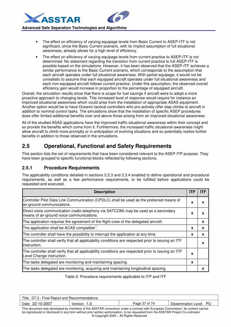
2.5.1 Procedure Requirements
The applicability conditions detailed in sections 2.2.3 and 2.3.4 enabled to define operational and procedural requirements, as well as a few performance requirements, to be fulfilled before applications could be requested and executed.
Description ITP ITF
Controller Pilot Data Link Communication (CPDLC) shall be used as the preferred means of air-ground communications.
x x
Direct voice communication (radio-telephony via SATCOM) may be used as a secondary means of air-ground voice communications.
x x
The application requires the agreement of the flight crew of the delegated aircraft. x
The application shall be ACAS compatible1. x x
The controller shall have the possibility to interrupt the application at any time. x x
The controller shall verify that all applicability conditions are respected prior to issuing an ITF instruction.
x
The controller shall verify that all applicability conditions are respected prior to issuing an ITP Level Change instruction.
x
The tasks delegated are monitoring and maintaining spacing. x
The tasks delegated are monitoring, acquiring and maintaining longitudinal spacing. x
Table 2: Procedure requirements applicable to ITP and ITF
Advanced Safe Separation Technologies and Algorithms
Title: D7.3 - Final Report and Recommendations
Date: 22-10-2007 Version: 1.0 Page 38 of 74 Dissemination Level: PU
Note 1: Since ACAS is mandatory on all large civil aircraft worldwide, it is assumed that all aircraft are equipped with ACAS/TCAS II. This system provides warning and advisories to the crew if near mid-air collision is predicted within a time-scale of about 40 seconds, and will thus act as a safety net. It should be noted that no credit may be given to ACAS/TCAS II in the safety calculations; ACAS/TCAS II is a pure safety net outside an otherwise safe system.
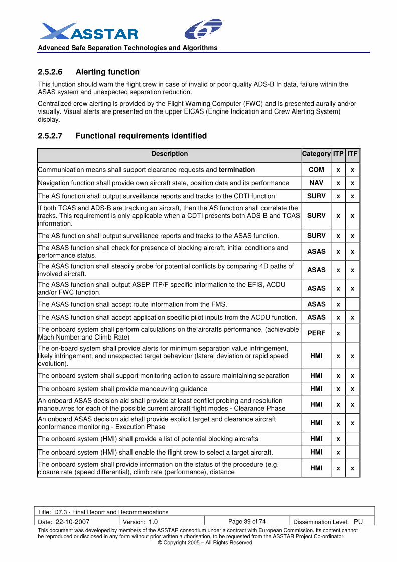
2.5.2 Functional requirements
2.5.2.1 Communication function
The ASEP-ITP application could be implemented with either HF (High Frequency) voice communications or CPDLC (Controller-Pilot Data link Communication). New phraseology or CPDLC messages will be required for this procedure to allow the flight crew to request the clearance and to identify the target aircraft. Any new phraseology developed must be consistent with current standards, practices, and guidelines outlined in the applicable ICAO Annexes and PANS. It must also be compatible with other ASAS applications.
HF datalink is considered to be the only means for transmitting messages between pilot and controller. HF is currently being used for voice communication, but with an inappropriate latency for the ASEP procedure requirements.
SATCOM is used occasionally, as secondary means of voice communication in emergency situations. The applicability of SATCOM to support ASAS is currently been assessed in another European research project, ASPASIA. Depending on its outcome, SATCOM could be considered as a potential option.
2.5.2.2 Navigation function
Regarding the ASAS operations the position data, which incorporate own aircraft position and also the other traffic positions derived from ADS-B reports, are very important data. The accuracy and integrity of those data are therefore required to be not below certain thresholds.
To assure integrity of own position data redundant (different, independent) data sources should be used. In the Oceanic environment the application of short range radio navigation is not relevant. So long range navigation systems like LORAN-C combined with an inertial guidance may be used to complement Global Navigation Satellite System (GNSS) positioning in that area.
The navigation system should include at a minimum two fully serviceable GNSS receivers, an Inertial Reference Systems (IRS) and a DME.
It is highly desirable that the navigation system employed for the provision of steering guidance is capable of being coupled to the autopilot.
Furthermore two fully serviceable independent primary flight level measurement systems are required; one automatic flight level-control system and one flight level-alerting device.
2.5.2.3 Surveillance data processing function
With respect to ASAS function the airborne surveillance (AS) function is a core element and therefore is relevant to all applications.
2.5.2.4 Performance calculation function
This function is valid for ASEP-ITP where the initial conditions reflect the applicability of the procedure. For ASEP-ITP the possible Mach number and Climb Rate need to be assessed before setting up the procedure.
2.5.2.5 HMI – Separation monitoring and maintaining separation
The crew interface for selection of the target aircraft is required in primary / forward field of view. Also display considerations to distinguish selected aircraft on the integrated Navigation and traffic display are required.
Advanced Safe Separation Technologies and Algorithms
Title: D7.3 - Final Report and Recommendations
Date: 22-10-2007 Version: 1.0 Page 39 of 74 Dissemination Level: PU
This function should warn the flight crew in case of invalid or poor quality ADS-B In data, failure within the ASAS system and unexpected separation reduction.
Centralized crew alerting is provided by the Flight Warning Computer (FWC) and is presented aurally and/or visually. Visual alerts are presented on the upper EICAS (Engine Indication and Crew Alerting System) display.
2.5.2.7 Functional requirements identified
Description Category ITP ITF
Communication means shall support clearance requests and termination COM x x
Navigation function shall provide own aircraft state, position data and its performance NAV x x
The AS function shall output surveillance reports and tracks to the CDTI function SURV x x
If both TCAS and ADS-B are tracking an aircraft, then the AS function shall correlate the tracks. This requirement is only applicable when a CDTI presents both ADS-B and TCAS information.
SURV x x
The AS function shall output surveillance reports and tracks to the ASAS function. SURV x x
The ASAS function shall check for presence of blocking aircraft, initial conditions and performance status.
ASAS x x
The ASAS function shall steadily probe for potential conflicts by comparing 4D paths of involved aircraft.
ASAS x x
The ASAS function shall output ASEP-ITP/F specific information to the EFIS, ACDU and/or FWC function.
ASAS x x
The ASAS function shall accept route information from the FMS. ASAS x
The ASAS function shall accept application specific pilot inputs from the ACDU function. ASAS x x
The onboard system shall perform calculations on the aircrafts performance. (achievable Mach Number and Climb Rate)
PERF x
The on-board system shall provide alerts for minimum separation value infringement, likely infringement, and unexpected target behaviour (lateral deviation or rapid speed evolution).
HMI x x
The onboard system shall support monitoring action to assure maintaining separation HMI x x
The onboard system shall provide manoeuvring guidance HMI x x
An onboard ASAS decision aid shall provide at least conflict probing and resolution manoeuvres for each of the possible current aircraft flight modes - Clearance Phase
HMI x x
An onboard ASAS decision aid shall provide explicit target and clearance aircraft conformance monitoring - Execution Phase
HMI x x
The onboard system (HMI) shall provide a list of potential blocking aircrafts HMI x
The onboard system (HMI) shall enable the flight crew to select a target aircraft. HMI x
The onboard system shall provide information on the status of the procedure (e.g. closure rate (speed differential), climb rate (performance), distance
HMI x x
Advanced Safe Separation Technologies and Algorithms
Title: D7.3 - Final Report and Recommendations
Date: 22-10-2007 Version: 1.0 Page 40 of 74 Dissemination Level: PU
Table 3: Functional requirements applicable to ITP and ITF
2.5.3 Safety Requirements
Safety requirements in the ASEP category of applications take into account that the separation responsibility and separation assurance is no longer performed by the ATCO, but by the flight crew.
The resulting impact and safety requirements drawn-up are:
• No complementary and independent mode of ground surveillance can be assumed during the ASAS manoeuvre.
• Safety is entirely dependent on the on-board ASAS implementation which:
o Obtains & calculates target separation.
o Calculates the separation manoeuvre.
o Guides aircraft along that manoeuvre, leaving the regular flight trajectory, and within the procedural envelope.
o Maintains separation with the target ensuring that the applicable airborne separation minima are never transgressed.
• The on-board ASAS implementation will also need to provide monitoring, and alerting to anticipate possible loss of (airborne) separation.
Failure in any of the above list leads to potential collision. In aviation safety terms such a situation is considered hazardous and will require an appropriate level of system and cockpit implementation.
The identified safety objectives described within the safety assessment were used as basic input to identify the key safety requirements. In general all operational hazard analyses (OHA) which are assessed with a severity of one and a Safety Objective of extremely remote were considered. The safety analysis already proposed some mitigation means to reduce the risk of chosen OHA.
Afterwards the approach was to proceed by selecting relevant hazards, identify respective events and mitigation means, which feeds into the compliance with safety requirements.
2.5.3.1 ASEP-ITP
After analysis, relevant safety requirements were extracted by comparing the abnormal events with appropriate mitigation means. They were mainly alerts and the level of automation that could help in lowering the risk of occurrences. In fact, they are highly relevant for infrastructure purposes.
SR-001 ASAS system shall provide information on the ITP criteria and their status to EFIS.
SR-002 GNSS positioning shall be complemented by independent navigational data from long range radio navigation and inertial reference systems.
SR-003 ASAS system shall consider only ADS-B qualified aircraft as blocking aircraft.
SR_004 ASAS system shall provide termination cues to EFIS as reminder to the pilot.
Table 4: Mitigation means for ASEP-ITP
The EFIS function shall present the target aircraft in a unique manner, when it is entered on the ACDU.
HMI x x
The FWC function shall provide a level 2 alert for the actual infringement of the [5] NM minimum longitudinal separation.
ALERT x x
The FWC function shall provide a level 1 alert for the predicted infringement of the [5.5] NM longitudinal separation.
ALERT x x
Advanced Safe Separation Technologies and Algorithms
Title: D7.3 - Final Report and Recommendations
Date: 22-10-2007 Version: 1.0 Page 41 of 74 Dissemination Level: PU
Several mitigations means were identified helping in lowering the risk of potential hazards. The following table shows some main mitigation means:
SR-006 ADS-B message supporting ASAS operations shall include integrity, accuracy and availability of the data contained in the message.
SR-010 The ASAS system shall provide pilot with continuous monitoring of the spacing value and shall trigger aural alarm in case of spacing violations. The same tool should be available to the controller in order to promptly detect wrong spacing values in case of failure of ASAS on board.
SR-014 The ASAS system shall inform pilots when the cleared flight level has been reached. The same tool should be available to the controller in order to promptly reveal any flight level violations.
SR-017 In case of loss of HF communications, ASAS system increases the safety of the flight only if other conditions are nominal. If so, the pilot will be able to continue ITF application using on board information.
SR-018 Controllers shall be provided with a tool able to show the existing spacing value between aircraft involved in the application. In case the cleared spacing value is below the non ASEP-ITF separation minima, the required tool shall not trigger any alarm.
Table 5: Mitigation means for ASEP-ITF
2.6 ASEP-ITP and ASEP-ITF summary
The ASEP-ITP and ASEP-ITF applications were developed in response to the need for expansion of the ATSA-ITP procedure under development for oceanic airspace, aiming at increasing the frequency of occurrence as well as evaluating an airborne separation application in a low density environment.
The simulations performed enabled the conduction of a cost/benefit analysis as well as confirming the potential additional operational benefits brought by ASEP-ITP and ASEP-ITF compared with ATSA-ITP.
One of the findings in the process is that a significant number of level or track change opportunities are today ignored due to lack of awareness from pilots. The introduction of CDTI with associated ATSA procedures could be already a valuable first step.
The safety assessment was conducted showing the way forward towards self-separation, while enabling the development of an operational procedure including clarification on the roles of all actors.
In order to support real time simulations conducted by the project, the systems HMI and technology aspects were progressed significantly, as well as procedures and human factors issues.
Advanced Safe Separation Technologies and Algorithms
Title: D7.3 - Final Report and Recommendations
Date: 22-10-2007 Version: 1.0 Page 42 of 74 Dissemination Level: PU
Following a presentation by NATS, at the ASAS-TN2 workshop 3 (11th-13
th September 2006 – Glasgow), a
proposal was developed to use a variant of ASEP-ITF (which became known as Airborne Separation In Trail Merge) to allow for the re-routing of eastbound traffic within the Shanwick Oceanic Control Area, to improve flight flexibility and manage European domestic airspace congestion.
The current situation for eastbound traffic during the duration of the eastbound OTS is that traffic is often following a routing which is not optimum in terms of flow management from an overall ATC point of view. ASEP-ITM enables the re-routing of aircraft to another oceanic exit point, after 20 West, to reduce ATM complexity, and/or improve the remaining route towards destination.
ASEP-ITM is an Airborne Separation PO-ASAS category application, for use by organised track flights, or random flights, within North Atlantic oceanic airspace.
The strategic ATC concept employed in the North Atlantic, coupled with the large geographical area available, results in very high levels of capacity well in excess of the capability of adjacent domestic centres to feed traffic into or receive traffic from the NAT. In effect, the NAT is capacity unconstrained.
Another characteristic of the NAT is that the traffic pattern during the eastbound flow has a “funnelling” effect, with traffic originating over a wide range of latitudes from northern North America to South America and concentrating into a relatively small area, with the majority of traffic landing in the London TMA, Paris TMA, Amsterdam and Frankfurt (around 40% of eastbound NAT traffic lands in the London TMA alone). Therefore the traffic tends to arrive over a very short period of time, coinciding with the first rotation of intra-European traffic; the result is often that the European flights encounter delays until the transatlantic traffic abates.
Figure 17: Possible organisation of OTS streams by final destination
Advanced Safe Separation Technologies and Algorithms
Title: D7.3 - Final Report and Recommendations
Date: 22-10-2007 Version: 1.0 Page 43 of 74 Dissemination Level: PU
In order to minimise fuel burn, airlines and ANSP continually seek NAT separation reductions which will allow aircraft to fly closer to their optimum profile. As a result of this demand, plans are in place for reductions in longitudinal and lateral separations in the NAT in 2009 and 2010, respectively. These separation reductions have the potential to more than double traffic concentrations into the busiest European domestic sectors, thus greatly exacerbating the problem of traffic streaming.
3.2 Outline of the procedure
A major factor in preventing traffic streaming is the current longitudinal separation required for flights which have not reported over a common point. In the figure below, the two red aircraft may be separated at 10 minutes apart, since their longitudinal relationship has been established by their position reports and any errors in forward position estimates can be assumed to cancel out since they both experience similar weather. In the case however, where it is desired to move the rear red aircraft onto the same track as the blue aircraft, this “cancelling-out” of weather errors cannot be assumed to have occurred as they will have experienced different weather up to that point in the flight. It is therefore necessary to apply an increased longitudinal separation of 15 minutes in this case (and 15 minutes with any following aircraft on that track). Because of the need for these large longitudinal separations, this particular re-routing manoeuvre is rarely applied in the NAT. However, the front red aircraft could be moved onto the same track as the blue aircraft using ASEP-ITM separation.
Figure 18: NAT Longitudinal In trail separations, and ASEP-ITM traffic streaming
3.3 Results of ASEP-ITM Simulations from Oceanic Traffic Data
3.3.1 ASEP-ITM Simulation Description
ASSTAR developed sample operational criteria for the applicability of this application. These were applied in a series of fast-time simulations. The goal of these simulations was to quantify how often it is possible to perform the suggested rerouting, using both current procedural rerouting (based on 15 minutes separation), and airborne delegated separation using the ITM procedure based on different separation values in the range of 2 to 6 minutes.
Using an algorithm to relate an aircraft’s final destination to its optimum oceanic exit point, the traffic sample was run, and when a flight reached 20W, if its re-routing was feasible, depending on the current and estimated traffic situation, it began to re-route. Note that no flight was considered for a re-route more than 1 degree north or south (i.e. only to the adjacent track), and only flights on OTS tracks were considered.
• Three simulation categories were examined:
o Airborne separation vis-à-vis traffic ahead and traffic behind.
15 minutes
10 minutes
4 minutes
ASAS Non ASAS
Advanced Safe Separation Technologies and Algorithms
Title: D7.3 - Final Report and Recommendations
Date: 22-10-2007 Version: 1.0 Page 44 of 74 Dissemination Level: PU
o Airborne separation vis-à-vis traffic ahead and procedural (15 minutes) separation with traffic behind.
o Procedural (15 minutes) separation with traffic ahead and airborne separation vis-à-vis traffic behind.
The following figure shows a snap-shot of one simulation in progress with traffic being rerouted where possible. The colour of each aircraft indicates the procedure being used:
• White: The current track is appropriate for the destination,
• Light Blue: Re-routing to North is preferred but is not feasible,
• Blue: Re-routing to North is preferred and is performed using 15 minute procedure,
• Dark Blue: Re-routing to North is preferred and is performed using ASEP-ITM procedure,
• Light pink: Re-routing to South is preferred but is not feasible,
• Red: Re-routing to South is preferred and is performed using 15 minutes procedure,
• Dark Red: Re-routing to South is preferred and is performed using ASEP-ITM procedure.
Figure 19: Oceanic traffic with simulated re-routings
3.3.2 Simulation Results
The following figure summarizes the results of the simulations based on seven days of oceanic traffic. Each column corresponds to a day. These simulations were performed using a separation value of 4 minutes for ASEP-ITM. (Results were also calculated for an ASEP-ITM procedure based on 2 and 3 minutes separation)
Advanced Safe Separation Technologies and Algorithms
Title: D7.3 - Final Report and Recommendations
Date: 22-10-2007 Version: 1.0 Page 45 of 74 Dissemination Level: PU
The top of the column gives the total number of eastbound OTS flights during the period of the eastbound tracks. The total number of flights of interest is 2342.
The dark-blue part labelled “rerouted 1515” corresponds to the number of re-routes that were possible using the current procedural 15 minutes separation (ahead and behind).
The purple part labelled “ITM 4” shows all the possible ASEP-ITM manoeuvres using 4 minutes airborne separation (i.e. with all other flights, where standard procedural separation did not already exist).
The cream section labelled “interested but not re-routable (4)” are those aircraft which would prefer a different routing but are blocked by aircraft on adjacent tracks at separations less than the 4 minutes used in this simulation.
The light blue section labelled “not interested in re-routing” are those aircraft already on their optimal track as defined by the destination algorithm.
Figure 20: Summary of ASEP-ITM Simulation Results (7 days)
Figure 21: Summary of ASEP-ITM Simulation Results (Overall)
The above pie-chart illustrates that about half of all flights (1210/2342) are not on their preferred track (as defined by the destination algorithm). This figure highlights the bottleneck in the following radar space due to the high shunting demand.
Advanced Safe Separation Technologies and Algorithms
Title: D7.3 - Final Report and Recommendations
Date: 22-10-2007 Version: 1.0 Page 46 of 74 Dissemination Level: PU
The figure shows that a third of the aircraft which it would be beneficial to re-route could be re-routed using procedural separation of 15 minutes. A further third can be re-routed using ASEP-ITM with a 4 minutes airborne separation value. The remaining aircraft are blocked by aircraft on adjacent tracks at separations below the 4 minute value used.
3.4 Aircraft Systems Requirements for ASEP-ITM
This section summarises the investigation of aircraft navigation systems performance and capability in the context of ASEP-ITM.
The requirements concern both:
• The aircraft performing the ASEP oceanic reroute manoeuvre (ownship - clearance aircraft Navigation and ASAS).
• Target aircraft (ADS-B out).
The performance requirements for the ASEP-ITM were derived from existing requirements for aircraft in oceanic airspace (i.e. MNPS requirements) and included:
• RNP-4 performance levels as per the ICAO guidance material in the performance based navigation (former RNP) manual (ICAO Doc. 9613).
• In support of oceanic separation down to 30 NM (30/30 separation criteria).
The basis of onboard separation responsibility for ASAS separation application imposes a change in the requirements allocation which also applies in determining the performance requirements for the ASEP ITM application. These changes were investigated as part of this analysis. The investigation then proposed candidate equipment which could support the ASEP-ITM application in oceanic airspace.
3.4.1 Performance Requirements for ASEP-ITM
Due to ASAS separation environment, and hazard severity levels, System and Navigation integrity requirements have been raised by two orders of magnitude - this is a preliminary estimate to cater for reallocation of the ATC ground component System and Navigation integrity performance to the aircraft performance in an ASAS separation scenario.
The system attributes considered in specifying the requirements for ASEP-ITM in this analysis included:
• Horizontal Accuracy – deemed identical and compatible with RNP-4 requirement.
• System Integrity – Classed as a ‘severe’ requirement due to the separation responsibility onboard and consequent collision risk.
• Navigation Integrity - Overall Navigation Integrity (Performance based navigation (PBN) RNP-4 requirement is 10
–5 per flight hour) for each aircraft involved: 10
–7 per flight hour.
• Navigation Position Continuity - Identical and compatible with RNP-4 requirement.
• Signal in Space - Identical and compatible with RNP-4 requirement, GNSS being mandatory.
3.4.2 Proposed ASEP-ITM Navigation Equipment
Amongst the Long range navigation systems used in MNPS airspace, the technical discussion on airborne equipage is restricted to GNSS based systems, where aircraft based augmentation system (ABAS) is required in meeting the requirements.
The systems considered are multi-sensor systems incorporating Global Positioning System (GPS), with integrity provided by RAIM - Receiver Autonomous Integrity Monitoring (e.g. systems approved under FAA AC20-130A) ; or with integrity provided by AAIM - Aircraft Autonomous Integrity Monitoring : which through redundancy of position estimates from multiple sensors, including GNSS, provides integrity performance that is at least equivalent to RAIM (e.g. systems approved under TSO C-115b, JTSO C-115b).
Advanced Safe Separation Technologies and Algorithms
Title: D7.3 - Final Report and Recommendations
Date: 22-10-2007 Version: 1.0 Page 47 of 74 Dissemination Level: PU
Dispatch fault detection and exclusion (FDE) availability prediction program will not be appropriate for ASEP Oceanic reroute applications.
The main systems for consideration were therefore:
• Either GNSS and Inertial systems, with GPS integrity monitoring and GPS/Inertial coupling,
• Or Two GNSS [GPS+RAIM] noting however that this configuration is vulnerable to loss of GPS during the ASAS separation manoeuvre, leading to loss of accurate positioning means to ensure required performance thereby implying a procedural mitigation scenario (dead reckoning, or recovery by ATC).
3.5 Operational Hazard Assessment for ASEP-ITM
This section describes the hazard assessment of the ASEP-ITM application undertaken in the ASSTAR project. The intention of this assessment was to specify the maximum tolerable likelihood of hazard effects for the application of ASEP-ITM in oceanic airspace. The main objective being to identify an appropriate list of hazards and related effects in order to derive the associated safety objectives, to be assigned to those identified hazards. This activity drew on the previous hazard assessments undertaken for the other applications considered in the ASSTAR project.
3.5.1 Approach and methodology
The analysis used the EUROCAE ED-78A/RTCA DOC-264 methodology as a means to establish the operational, safety, performance and interoperability requirements for ATS supported by data communications, to assess their validity, and to qualify the related CNS/ATM System. This included ground based elements, operational procedures, including the human and aircraft equipage.
The Operational Hazard Analysis (OHA) is part of the methodology; it is defined as a qualitative assessment of the operational hazards associated with the Operational Services and Environment Definition (OSED). This approach was used to generate a hazard analysis for the ASEP-ITM application. The main output from the assessment was a list of safety objectives to be assigned to the identified hazards.
The process adopted to perform this initial operational safety assessment was intended to cover only failures directly affected by the introduction of ASEP-ITM applications. It consists of hazard identifications and allocation of severity classes from the Severity Classification Scheme. For each identified hazard an initial estimation of severity has been performed looking at the worst credible case. Safety objectives have then been derived in order to provide an acceptable frequency of occurrence for the identified hazards.
3.5.2 Hazard Analysis Summary
A number of failure modes leading to the hazard effects were identified. The applied failure modes considered are similar to those used by the ADS-B Requirement Focus Group (RFG):
• Loss: action not available or not executed.
• Incorrect: Action performed using incorrect information or incorrectly performed.
• Misdirection: message sent to an unintended aircraft.
• Others: actions executed in non suitable conditions, or executed after or before the expected moment.
The hazards which were identified from the failure modes and subsequently investigated included:
• Missed and incorrect visualization of information needed by the ATCO.
• Pilot inserts a wrong target aircraft in the system.
• Nomination of the target to the wrong clearance aircraft.
• ADS-B In/Out does not work properly for one or both clearance and target aircraft.
• Pilot initiates a manoeuvre not compliant with the ASEP-ITM criteria.
Advanced Safe Separation Technologies and Algorithms
Title: D7.3 - Final Report and Recommendations
Date: 22-10-2007 Version: 1.0 Page 48 of 74 Dissemination Level: PU
• Airborne premature/late determination of termination point.
• Aircraft fails to report passing of ITM instruction limit.
For each of these hazards a severity level was assigned and a safety objective derived giving the tolerable frequency of occurrence of the hazard.
3.6 ASEP-ITM Summary
The ASEP-ITM application has been developed in response to a potential operational issue. The work-package developed an operational concept into a formalised Operational Services & Environment Description.
A simulator platform was developed and recorded operational data analysed to determine the applicability of the procedure in the current environment. This identified that 2/3 of aircraft which it would be beneficial to ATC to re-route could be rerouted with either the current 15 minute procedure or with the ASEP-ITM procedure.
Additionally an initial operational hazard analysis was conducted to characterise the hazards in the application and assign safety objectives. A review of navigation performance requirements was also conducted which identified candidate equipment needs for the application.
Advanced Safe Separation Technologies and Algorithms
Title: D7.3 - Final Report and Recommendations
Date: 22-10-2007 Version: 1.0 Page 49 of 74 Dissemination Level: PU
4. ASAS SELF-SEPARATION FREE FLIGHT TRACK (SSEP-FFT)
4.1 Concept and scenarios
4.1.1 Operational purpose
The North Atlantic System has a series of existing shortcomings, as identified by the North Atlantic Systems Planning Group, working on behalf of the International Civil Aviation Organisation (ICAO). These shortcomings are identified to be structural, that is inherent to the system itself and means that the users currently do not enjoy maximum economy in their operations with minimum restrictions. Refer to sections 3 and 4 for a description of the current oceanic environment.
The surveillance and communication systems limit the ATC capabilities in the NAT. Manual waypoint insertion errors for example can cause Gross Navigational Errors and the current surveillance system provides only a limited ability to detect those errors and to contain them by ATC intervention. The ATC limitations dictate relatively large separation minima and this in turn limits exploitation of the airspace capacity. While the NAT as a whole is not saturated, a local ‘capacity’ shortfall can occur in the busiest part of the Europe/North America axis. This constrains aircraft profiles: aircraft may not obtain the desired route or flight level and therefore must be re-cleared on a less optimal flight profile.
The safety of the system is measured against an agreed TLS which identifies the risk of a mid-air collision and is expressed as an agreed mathematical formula. This ensures that, if errors occur, which have a direct impact on the continuation of safe operations, there are agreed abnormal and emergency procedures. The route structure is such that these procedures can be safely applied; in general procedures anticipating abnormal situations or emergencies have an adverse impact on the capacity and efficiency of the system.
The concept is to alleviate these limitations by the introduction of free flight airspace (FFAS). In this way it should be possible to optimise the use of airspace. And as a first step towards FFAS the implementation of a designated Free Flight Track (FFT) within the current structure of the OTS is proposed.
Therefore, the SSEP-FFT application has initially been designed for use in oceanic airspace. The oceanic track that will be designated as FFT will be promulgated by the airspace planning and management service on a daily basis to reflect the demand patterns expected across the NAT airspace. This will take into account the forecast traffic flow densities, forecast meteorological conditions, capabilities of flights and the balance of benefit to the users’ quest for flexibility and economy.
Less capable aircraft will not be allowed to access the FFT, therefore the aim will be to adjust the position of the FFT to maximise the benefits for capable aircraft, while providing an incentive for aircraft operators with less capable aircraft to upgrade their avionics fits.
For this first step autonomous operation is not foreseen to be usable in areas adjacent to the NAT airspace. In other words, upon exiting the NAT OTS, Managed Airspace with regular radar control will be entered again. This leads to the consequence that aircraft need to enter and exit the FFT. Once aircraft exit the FFT the (domestic) controller has to resume separation responsibility. ATC will typically apply exit conditions to deal with this, constraining aircraft flying on the FFT.
Reserving a favourable Oceanic track for Self-Separation traffic has a clear economic advantage for cruising aircraft; in this way operators are encouraged to equip their fleet. Another advantage of this method is that it allows a gradual transition to Self-Separation by adding FFT(s) and subsequently clustering FFTs into a volume of airspace, making it more acceptable when introduced.
A small percentage of aircraft currently cross the OTS structure. There is nothing that prevents an operator from planning a route that crosses the OTS. However, in this case, operators must be aware that today re-routes or significant flight level changes from those planned are very likely to be necessary during most of the OTS traffic periods. The FFT may slightly change this situation for the worse. ATC will never be able to clear random traffic across the FFT at the normally-used flight levels.
Advanced Safe Separation Technologies and Algorithms
Title: D7.3 - Final Report and Recommendations
Date: 22-10-2007 Version: 1.0 Page 50 of 74 Dissemination Level: PU
The proposed SSEP-FFT would transfer responsibility for separation between all aircraft from the controller to the crews of aircraft operating on the FFT. The SSEP-FFT application will enable an aircraft to climb or descend, to speed up or slow down in situations where current oceanic operations would prevent it. The avionics accuracy and integrity requirements for SSEP-FFT are likely to be rather demanding and the changes to current roles and responsibilities would be significant. SSEP-FFT would require the crew to use airborne surveillance information provided on the flight deck to prevent, detect and resolve conflicts with other aircraft on the FFT. The controller would not be required to monitor aircraft on that track.
The primary benefit expected from SSEP-FFT is the fuel-saving achieved by enabling aircraft to fly at their optimum Mach number and optimum flight level. Secondary benefits include safety and passenger comfort benefits from an improved ability to avoid turbulent flight levels.
4.1.2 Outline of the procedure
The normal air-ground procedures for SSEP-FFT are solely related to FFT Entry and FFT Exit.
4.1.2.1 FFT Entry
Aircraft wishing to use the FFT will plan their routing and file their flight plan accordingly. ATC will be aware that the aircraft wishes to use the FFT from the requested oceanic entry point and FFT letter contained in the flight plan and confirmed in the oceanic clearance request. It will be the responsibility of the aircraft operator and flight crew to ensure that the aircraft is appropriately equipped to use the FFT.
The aircraft should be between 90 minutes and 30 minutes from reaching the oceanic boundary when it makes its Oceanic Clearance Request. The oceanic planning controller assesses the oceanic clearance request and checks that traffic loading on the requested FFT is acceptable for this flight to enter the FFT at the requested time. This requirement will be met in practice by using the current (standard separation) procedures for initial placing of aircraft on the FFT. This implies at least an initial 10 minute longitudinal spacing at FFT entry point for aircraft starting at a given level.
The oceanic planning controller issues an oceanic clearance for the FFT, giving the flight a time at the oceanic boundary, i.e. FFT entry point. The oceanic entry clearance will also specify an entry level. The oceanic (planning) controller coordinates the oceanic clearance with the domestic controller as normal.
The domestic controller continues to be responsible for the flight until reaching the oceanic boundary at the FFT Entry Point. Approaching the entry point the domestic controller advises the crew that the flight is leaving managed airspace and instructs the crew to establish CPDLC contact with oceanic control.
Once the aircraft passes the FFT entry point the oceanic (en-route) controller receives a position report as normal. The en-route controller has no responsibilities except to provide information, if asked, to the flight.
It is suggested that there should be a formal transfer of separation responsibility via an R/T exchange to confirm entry to the FFT.
4.1.2.2 FFT Exit
Aircraft leaving the oceanic track, on completing the oceanic crossing, will need to contact the domestic control centre in advance to obtain a clearance to enter managed airspace.
Note: There is currently no means for an aircraft in oceanic airspace to contact directly a domestic planning controller. The ground system and procedures for domestic control could be changed to allow direct contact from an aircraft in oceanic airspace. One way of doing this would be to use the data link “Down-Stream Clearance (DSC)” service to make data link contact with the domestic planning controller while still in oceanic airspace. This is assumed in the procedure described below.
The aircraft should be about 30-45 minutes from leaving oceanic airspace when it makes its domestic entry clearance request. At approximately the same time the flight plan is made available to the receiving ATS unit.
After the decision to request a domestic entry clearance the flight crew establish a DSC link to allow CPDLC communications with the domestic centre. Within the domestic centre this allows clearance requests to be
Advanced Safe Separation Technologies and Algorithms
Title: D7.3 - Final Report and Recommendations
Date: 22-10-2007 Version: 1.0 Page 51 of 74 Dissemination Level: PU
directed to the planning controller for the sector which the flight will enter. The flight crew uses this DSC link to request a clearance to re-enter domestic airspace. The clearance request will contain the oceanic exit point, estimated time at that point and requested exit level.
The domestic (planning) controller considers the details of the request and assesses it with other aircraft known to be exiting oceanic airspace at that time and other aircraft in domestic airspace. If acceptable, the domestic (planning) controller provides a clearance to enter based on the requested exit point, time and flight level. The domestic controller may choose to offer an alternative clearance with a different flight level.
The aircraft proceeds to the oceanic exit point in accordance with the accepted domestic entry clearance, manoeuvring as necessary on the FFT to get to the assigned exit level. After receiving the entry clearance the crew will aim to reach the exit flight level as soon as practical and thereafter will try to avoid level changes unless essential to maintain separation.
Once at the oceanic exit point/domestic airspace entry point the flight crew report to the domestic (tactical) controller on the assigned frequency.
4.1.2.3 Flight Operation on the FFT
As a typical example of operation on the FFT, an aircraft could take advantage of the significantly reduced longitudinal separation standard to perform a climb (or descent) whereas it would be blocked by any above aircraft less than 10 minutes in front or behind in the current OTS structure.
All aircraft are equipped for the FFT and consequently have qualified ADS-B OUT, ADS-B IN and Conflict Prevention, Detection and Resolution capabilities. Using SSEP-FFT functionality, and especially the conflict prevention capability, the clearance aircraft would make sure -prior to a manoeuvre- that it does not generate a conflict. In the example the aircraft would be able to climb one level, to reach FL350.
The second typical conflict case will be if the clearance aircraft is flying at the same level as another aircraft and is closing in on that aircraft. At a certain point a conflict will be detected, and the resolution algorithm will advise the clearance aircraft to decelerate or to perform a level change.
In normal operation without conflicts a manoeuvre will only be permitted if it does not generate a conflict, therefore relative positioning and groundspeed differential will be the basis of information that a crew will use to make a decision to manoeuvre.
4.1.3 Applicability Conditions
4.1.3.1 FFT Entry Procedure
For the FFT entry the crew must ensure the following conditions are satisfied before requesting an FFT clearance:
SSEP-FFT Qualification:
• The aircraft wanting to cross the NAT on a FFT has “SSEP-FFT Equipment”: providing the crew with tools for traffic awareness, and airborne traffic conflict management; and providing qualified ADS-B OUT to other aircraft on the FFT.
• The airline Operational Specifications of the SSEP-FFT Aircraft permit the FFT operations.
• The crew of the SSEP-FFT Aircraft is properly qualified for FFT.
SSEP-FFT Preconditions:
• The aircraft has planned their routing and filed their flight plan accordingly for the FFT. ATC will be aware that the aircraft wishes to use the FFT from the requested oceanic entry point contained in the flight plan and confirmed in the oceanic clearance request.
• The SSEP-FFT avionics must be operative.
Advanced Safe Separation Technologies and Algorithms
Title: D7.3 - Final Report and Recommendations
Date: 22-10-2007 Version: 1.0 Page 52 of 74 Dissemination Level: PU
• The SSEP-FFT aircraft’s position data must meet the accuracy and integrity requirement for SSEP-FFT. RNP 0.5 is currently considered to be an appropriate starting value for FFT research.
SSEP-FFT Initiation Criteria:
• The SSEP-FFT Aircraft is between 90 and 30 minutes from reaching the oceanic boundary.
SSEP-FFT Request:
• If the qualifications, preconditions, and criteria are met, the crew makes it Oceanic Clearance Request following existing procedures, including specifying that the flight is to enter the FFT.
4.1.3.2 FFT Exit Procedure
For the FFT exit the crew must ensure the following conditions are satisfied before requesting a domestic entry clearance:
SSEP-FFT Initiation Criteria:
• The SSEP-FFT Aircraft is between 90 and 30 minutes from reaching the oceanic boundary.
SSEP-FFT Request:
• If the criteria are met, the crew makes it Domestic Airspace Entry Request following newly designed procedures, including specifying that the flight is leaving a FFT.
Constraints have been taken into account for the applicability conditions as described in this section. One additional constraint has been identified. In case lateral resolutions are not allowed a deadlock situation could be foreseen due to blocking traffic above and below, and two aircraft at the same altitude with incompatible speed bands. A number of alternatives in the conceptual design are possible to address this issue.
• A common speed range for all aircraft. The speed performance of each aircraft that is given access the FFT should be such that they are able to fly at least a minimal common speed range, e.g. M.78-M.80 [values need to be discussed]. A disadvantage is that this alternative might severely restrict the access to and also the economics of the FFT.
• Shoulders to the FFT: in the nominal case aircraft would have to fly on the FFT, but in case of conflicts (and then possibly only as a last resort) the shoulder(s) of the track could be used for lateral conflict resolutions. It is proposed to have a shoulder with an offset of 6 NM relative to the FFT on one side or either sides of the nominal track. This also addresses comments from the airspace users as received during the first ASSTAR User Forum in Rome and the third ASSTAR User Workshop in Amsterdam. A disadvantage is that this alternative has a larger impact on the navigation (and possibly surveillance) requirements of aircraft operating on adjacent tracks.
Given the advances in navigation performance the second option is preferred and this option was considered as part of the conceptual design of the SSEP-FFT application in the last part of the ASSTAR project.
4.1.4 Roles and Responsibilities
• The flight crew of the SSEP-FFT aircraft plan their routing and file their flight plan accordingly for the FFT.
• The flight crew request an Oceanic Clearance including specifying that the flight is to enter the FFT.
• The Oceanic (Planning) Controller assesses the Oceanic Clearance Request and checks that traffic loading on the FFT is acceptable for the flight to enter the FFT at the requested time.
• The Oceanic (Planning) Controller issues an Oceanic Clearance for the FFT. This clearance is passed to the crew and the domestic controller.
• The crew is primarily responsible for complying with the oceanic entry requirements -given in the Oceanic Clearance- as normal. Nevertheless the domestic controller is tasked to deliver the
Advanced Safe Separation Technologies and Algorithms
Title: D7.3 - Final Report and Recommendations
Date: 22-10-2007 Version: 1.0 Page 53 of 74 Dissemination Level: PU
aircraft at the cleared entry point and entry level. If the intended separation is within 5 minutes of the required minimum, the domestic controller is responsible for feeding the aircraft into oceanic airspace at the correct separation (i.e. a time interval between the pair to ensure that minimum separation exists as communicated by the Oceanic planner).
• Once at the oceanic entry point the flight crew is advised that the flight is leaving managed airspace and is instructed to establish CPDLC contact with oceanic control. The flight crew now assumes responsibility for separation with other aircraft on the FFT. To successfully comply with this responsibility and to accomplish associated tasks the crew is supported by on-board tools for preventing, detecting and resolving conflicts. The crew may execute speed and altitude changes at their own discretion taking into account the vertical boundaries of the FFT. A rule should be designed for deciding which aircraft should manoeuvre to ensure the separation when several equipped aircraft are in conflict.
• At the appropriate time the flight crew request a Domestic Airspace Entry Clearance (using a DSC link) including specifying that the flight is preparing to leave the FFT.
• The Domestic Planning Controller assesses the Domestic Clearance Request with other aircraft known to be exiting oceanic airspace and other aircraft in domestic airspace.
• The Domestic Planning Controller issues a domestic entry clearance.
• The crew flies the aircraft as necessary to proceed to the oceanic exit point in accordance with the domestic entry clearance. Until passing the oceanic exit point the crew remains responsible for separating their aircraft with other aircraft on the FFT.
• Once at the oceanic exit point the flight crew report to the domestic (tactical) controller and after successful (radar) identification the domestic controller assumes responsibility for all separations.
4.2 Development and validation
4.2.1 Fast Time Simulations
Fast Time Simulations have been performed to investigate benefits of the SSEP-FFT application. The simulations have been done on the NLR TMX platform. The TMX studies covered all oceanic ASAS applications, for a limited number of scenario variables and indicators. The traffic sample used for the simulation is based on the actual traffic flown on Friday 16
th December 2005 provided by NAT. Starting from
the above baseline one other traffic sample has been generated by cloning and displacing in space and time the existing flights in order to achieve a doubling of the traffic density with respect to the one day sample. For the TMX simulations it was assumed that all aircraft were equipped for the application under investigation.
4.2.1.1 Scenarios
It was important to compare the results of SSEP-FFT with some baseline scenarios. The basic level scenarios are based on current separation criteria and level traffic, same FL along tracks. The basic current scenarios are based on current separation criteria and maximum use of climb step opportunities. The optimal scenarios correspond to aircraft flying their optimum altitude and speed profile, irrespective of other aircraft.
The following scenario characteristics are applicable to all simulations:
• The traffic sample is for a single 24 hour period.
• Oceanic Scenario: Full unidirectional traffic.
• Only traffic crossing the North Atlantic on the NAT OTS is considered.
• Mach number from EUROCONTROL Base of Aircraft Data (BADA) are considered the optimum Mach number as used during the cruise flight of that aircraft.
• For climb and descent the default speed schedules from BADA are used.
• No jet stream has been used in the fast time simulations.
Advanced Safe Separation Technologies and Algorithms
Title: D7.3 - Final Report and Recommendations
Date: 22-10-2007 Version: 1.0 Page 54 of 74 Dissemination Level: PU
The simulations were performed on all four scenarios BASIC LEVEL; BASIC CURRENT; SSEP-FFT; Optimal with the following variables:
Traffic density: 2005 2005 x 200%
Oceanic Track System: Westbound Eastbound
4.2.1.2 Findings on fast time simulations on SSEP-FFT
The TMX simulations were aimed at identifying the main differences between the current operational procedures and SSEP-FFT. The following trends can be found:
• The SSEP-FFT application showed significant improvements with respect to the fuel savings in comparison to the current practice. The savings are around 220kg of fuel per flight (around 0.8% of the fuel usage on the Oceanic track). The fuel savings are related to the increased number of step climbs performed. The fuel savings found for the SSEP-FFT application were very similar to the savings found for the ASEP-ITF application.
• The SSEP-FFT application showed a small effect on the average flight time in comparison to the current practice. Detailed analysis showed that the effect on flight time is limited to less than 10% of traffic. This means that some traffic can have a considerable decrease in flight time and most traffic has no significant effect in flight time.
• The throughput on the OTS is maintained when introducing SSEP-FFT in comparison to the Basic Level and Basic Current scenarios.
• With the current ground separation minima of 10 minutes around 75% of the potential for fuel savings (around 150kg of 200kg) can already be realised when traffic executes the step climbs when separation is adequate. In current practice though, a lot of opportunities for step climbs are not taken because pilots are not aware of these opportunities. This means that airborne traffic situational awareness in the cockpit would enable the flight crews to take these opportunities.
Overall, the simulation results show that there is scope for fuel savings if aircraft were to adopt a more proactive approach to changing levels. This increased level of response would require for instance an improved airborne traffic situational awareness which could arise from the installation of appropriate ASAS equipment. Another option would be to have Oceanic tactical controllers not only do control by exception, but also pro-actively offer step climbs to aircraft. The simulations show that the installation of specific ASAS separation procedures does offer limited further benefits over and above those arising from an improved traffic situational awareness.
# step climbs per aircraft on Westbound OTS
0,00
0,50
1,00
1,50
2,00
2,50
Basic
Level
Basic
Current
ATSA-
ITP
ASEP-
ITP
ASEP-
ITF
SSEP-
FFT
Basic
Optimal
Application
# S
tep
Cli
mb
s
Requested
Actual
Immediate
Double
# step climbs per aircraft on Eastbound OTS
0,00
0,50
1,00
1,50
2,00
2,50
Basic
Level
Basic
Current
ATSA-
ITP
ASEP-
ITP
ASEP-
ITF
SSEP-
FFT
Basic
Optimal
Application
# S
tep
Cli
mb
s
Requested
Actual
Immediate
Double
Figure 22: Number of step climbs for the 100% scenario
Advanced Safe Separation Technologies and Algorithms
Title: D7.3 - Final Report and Recommendations
Date: 22-10-2007 Version: 1.0 Page 55 of 74 Dissemination Level: PU
The NLR flight and ATC simulators were used for a pilot-in-the-loop and controller-in-the-loop evaluation of the application(s). The objective of the simulator trials was:
To evaluate the ASSTAR functionality with its HMI, applying new procedures and new task distribution between air and ground, in a simulated environment regarding pilot/controller acceptance, pilot/controller workload, pilot/system performance and pilot/controller behaviour.
This has been evaluated in a number of simulation runs in which system, procedure and/or environmental conditions were varied between the runs. The experimental design for the pilot-in-the-loop simulations integrates all conditions into one matrix covering all flights for all crews and makes sure that it is randomised over the crews. The controller-in-the-loop simulation was more an explorative experiment, in which mainly controller feedback was gathered and system enhancements were minimized to the addition of new CPDLC messages. Measurements taken in order to meet these objectives cover both subjective as well as objective measurements. However, the objective measures, such as minimum separation infringement, were initially analysed based on observations and, only if needed, was the recorded data looked at in more detail.
4.2.2.1 Environment
In addition the FFT was defined as follows:
• Track in between OTS tracks, assigned for self-separation operation.
• Vertical bounds FL310 to FL400, both inclusive.
• Conflict Prevention, Conflict Detection and Conflict Resolution functions operative.
• Resolution Advisories in the lateral, vertical and speed domain.
• For resolutions in the vertical domain, obey the vertical bounds.
• For resolutions in the lateral domain, nominally fly on the FFT, and perform an offset of maximum 6 NM (on both sides) for conflict resolution.
4.2.2.2 Scenarios
The piloted simulation focussed in the first place on nominal operations for ASEP-ITF, as major improvements had been carried by BAE Systems as a result of the first piloted experiment, and in the second place this simulation addressed non-nominal situations.
The non-nominal conditions contained detected and undetected failure conditions, undesired pilot behaviour and complex traffic situations. The failure conditions concerned the ASAS and ADS-B equipment of both own aircraft and relevant other traffic.
For each nominal and non-nominal situation 4 runs were selected, giving a total of 12 runs. The runs were grouped together such that 3 groups were created, two ITF groups and one FFT group. Within the FFT group and within the ITF groups the individual runs were selected randomly per flight crew.
In total 60 runs were performed, 40 for ASEP-ITF and 20 for SSEP-FFT. A brief description of the FFT runs is given in Table 6.
Advanced Safe Separation Technologies and Algorithms
Title: D7.3 - Final Report and Recommendations
Date: 22-10-2007 Version: 1.0 Page 56 of 74 Dissemination Level: PU
t=0 min GRACE wants to climb to FL390. After ~5 minutes there is the opportunity to climb
FFT015 Initial Conditions
KLM204 380 0.86 492 512 DAL66 BAW112
380 390
0.80 0.85
459 488
478 488
+34 +14
+11.5 -3.6
After N min GRACE has to take action, unable to slow down to DAL66 Mach number
When GRACE on offset route, DAL66 has emergency and passes closely in front, ADS- B FAULT of DAL66 � TCAS symbol for DAL66 on ND of GRACE. DAL66 turns 45 degrees, DAL66 (slowly) descend to FL375.
t=2-3 min GRACE: ADS-B FAULT, resulting in loss of ASAS functionality
ATC acts (after call of flight crew GRACE):
a. GRACE, report current speed b. GRACE, roger c. altn route north - GRACE, descend to level 350, proceed direct to N58W020, speed Mach .84 d. altn route south - GRACE, descend to level 350, proceed direct to N56W020, speed Mach .84 e. GRACE ready to copy route/oceanic clearance f. route north - GRACE proceed via N58W020 to MIMKU g. route south - GRACE proceed via N56W020, to MASIT
The experiment comprised one day per flight crew. In the morning pilots were briefed about the concept of ASAS separation operations. After the briefing the pilots were trained in the flight simulator for both the flight simulator as well as ASSTAR specific functions. Depending on the progress and questions from pilots this training included three or four flights of each 15 to 20 minutes. After this training session, the experiment flights started. The experimental flights took approximately 15 minutes each. The experimental flights were completed in the afternoon and were followed by the debriefing questionnaire and debriefing discussion.
The controller-in-the-loop experiment did not have such a rigid experimental design. The Shanwick OCA was simulated, but the traffic sample was limited to the OTS.Traffic samples were taken from the same day of operations on the NAT OTS. Four baseline scenarios of 40 minutes were created representing the beginning and ending of the daily eastbound flow, and two busy periods during the eastbound flow. Based on these scenarios either ITF scenarios were created with ITF operations on all five tracks or FFT scenarios were created where one track (the busiest one) was assigned as self-separation track.
For the first session six runs were performed:
• Two nominal ITF runs.
• Two non-nominal ITF runs.
• One nominal FFT run.
• One non-nominal FFT run.
For the second session seven runs were performed in which the following events were looked at:
• Aircraft requesting an ITF with no or incorrect flight identifier.
• Aircraft requesting an ITF for aircraft below instead of above, pilot misread -01 for +01.
• Self-separation track with 5 minutes periodic updates (run 602) vs. no periodic updates. In case of no periodic updates, only standard waypoint reporting is used, as a consequence predictions have unreliable level and speed information.
• 2000 ft ITF climb in combination with ITP.
• Aircraft requests climb/descent due to turbulence, ATCO first checks if standard climb is possible, then checks ITF climb, and the only way to grant this request is to instruct another aircraft to perform an ITF.
4.3 Operational, functional and safety requirements
4.3.1 Findings on real time simulations on SSEP-FFT
The following conclusions are drawn from the ASSTAR pilot-in-the-loop and controller-in-the-loop simulations regarding SSEP-FFT operations in a track-structured procedural environment.
The feasibility of the SSEP-FFT concept could not be refuted from either a pilot’s point of view or a controller’s point of view, no major irresolvable issues were revealed.
The most important (flight crew/aircraft) issues are:
• Offset routes (in the order of the lateral separation standard plus a small margin) are needed to resolve conflicts as integral part of this concept. The majority of resolutions were performed by means of a lateral manoeuvre, climb manoeuvres were typically not selected because aircraft were already flying at their optimum level or they were prohibited to do so due to other traffic.
• The Mach target of other traffic is needed. Future ADS-B definitions and implementations shall include the speed of the target aircraft.
• The intentions of other traffic are needed. A dedicated air-to-air frequency was often cited as the means to find out the intentions of nearby traffic.
• Rules to prohibit abuse and asocial behaviour are needed, e.g. a slow aircraft climbing just in front of a faster aircraft forcing that aircraft to manoeuvre.
Advanced Safe Separation Technologies and Algorithms
Title: D7.3 - Final Report and Recommendations
Date: 22-10-2007 Version: 1.0 Page 58 of 74 Dissemination Level: PU
The most important (controller/ground) issues are:
• Transition from oceanic airspace to domestic airspace needs to be investigated; the effect of self-separation oceanic tracks -that end at the boundary between oceanic and domestic airspace- on domestic air traffic control is a concern.
The following (flight crew/aircraft) issues need further consideration/attention:
• SSEP-FFT makes it necessary to also look behind you. Nowadays, flight crews do not use the ND ROSE mode when flying in Oceanic airspace.
• Checklist procedures are needed in case of failure conditions, e.g. ADS-B, Conflict Detection, similar to all other failure conditions that may occur on-board the aircraft.
• The contingency procedure to leave the FFT shall be developed in detail, the standard contingency procedure for leaving oceanic tracks is not sufficient.
• The readability of data tags, displayed above the traffic symbols on the ND, was poor due to clutter, colour and font size.
The following (controller/ground) issues need further consideration/attention:
• Direct pilot-controller voice communication is needed for the contingency procedure to leave the Self-Separation track, due to the fact that the messages are too complicated for data link.
• More preset datalink messages would be required for this procedure.
4.3.2 Safety Assessment
The main objective of the safety work was to provide the results of a qualitative and quantitative risk assessment for the Airborne Self-Separation – Free Flight on an Oceanic Track (SSEP-FFT) application.
4.3.2.1 Qualitative Safety Assessment
The qualitative risk assessment for the Self Separation Free Flight on Track (SSEP-FFT) included a description of the application and an Operational Hazard Assessment (OHA). This work served as a base for a quantitative risk assessment which was conducted later.
The most important existing result for the development of an OHA for Self-Separation on an OTS is the ‘Initial OHA’ for this application, which has been developed at the early stages of the project. Actually, this initial OHA was further developed. In the development of the initial OHA extensive use was made of the OHA developed for Application A5 of the Mediterranean Free Flight (MFF) program (the “airborne Self Separation” application).
In the MFF A5 operation, pilots had the freedom to select their heading, altitude and velocity; in the ASSTAR SSEP-FFT operation pilots are allowed to select their altitude and velocity freely, but they are restricted to stick to their track.
For the scope of the initial OHA for SSEP-FFT, the following assumptions were taken:
• Transitions in time are not considered, it is assumed that the application is steady.
• Transitions in space are not considered.
• Some effects of global hazards are not fully included (e.g., for a global navigation failure only the effect on one pair of aircraft is considered).
• The effects of multiple concurrent conflicts are not fully considered.
• Crossing and opposing traffic are out of scope.
• Aircraft flying outside of the width of the track are out of scope.
• The collision avoidance functionality of TCAS is out of scope.
Advanced Safe Separation Technologies and Algorithms
Title: D7.3 - Final Report and Recommendations
Date: 22-10-2007 Version: 1.0 Page 59 of 74 Dissemination Level: PU
Next, the consequences (or ‘effects’) of the operational hazards were identified, the conditional probabilities (the probability that the worst case effects occur, given the occurrence of a hazard) were estimated and the applicable safety criteria were used to deduce Safety Objectives: the acceptable frequency of occurrence per operational hazard.
OH_1 The co-operative phase is entered while at least one of the two aircraft has a navigational problem being an altitude estimate error, or being a horizontal positioning error with at least a longitudinal component.
The two aircraft in conflict do not have correct information about their relative positions.
In case of a longitudinal position estimate problem, both aircraft may well fly at the same altitude, as they may have the same optimal altitude.
In case of an altitude estimate problem, the aircraft may also fly coincidentally on the same altitude.
A mid-air collision could be the consequence.
1
OH_2 The co-operative phase is entered, while one crew is expected to solve it and the other crew is not expected to do an adverse manoeuvre.
One of the crews is expected to solve the conflict, while the other crew is not expected to do an adverse manoeuvre. The workload will be increased as the conflict is in the co-operative phase. Only one of the two flight crews is fully controlling the situation.
4
OH_3 The co-operative phase is entered, while one crew is expected to solve it, and the other crew may do an adverse manoeuvre.
One of the crews is expected to solve the conflict, but the other crew may do an adverse manoeuvre. As such, neither one of the crews does fully control the situation. Even though the aircraft are still three minutes from a separation underscore when entering the co-operative phase, it cannot be ruled out that such a separation underscore will be prevented. As one usually has a 2
nd CR proposal
available, as one can also contact the other crew via R/T, and as at least one crew is expected to be alert to the situation, it is unlikely that the separation underscore gets to be major.
3
OH_4 An additional conflict is entered
The crew will enter a new conflict, in which the time to protrusion of the protected zone can be between 0 and 6 minutes. In this additional conflict the standard conflict detection and resolution may be hampered by the other aircraft involved in the initial conflict. The additional conflict may therefore only be solved after a separation underscore.
3
Table 7: Operational Hazards assessment for SSEP-FFT
Applying the risk classification scheme, a Safety Objective can be deduced for each Operational Hazard, as listed below:
OH # OH description SO: Likelihood
OH_1 The co-operative phase is entered while at least one of the two aircraft has a navigational problem being an altitude estimate error, or being a horizontal positioning error with at least a longitudinal component.
No greater than Extremely Improbable
Advanced Safe Separation Technologies and Algorithms
Title: D7.3 - Final Report and Recommendations
Date: 22-10-2007 Version: 1.0 Page 60 of 74 Dissemination Level: PU
OH_2 The co-operative phase is entered, while one crew is expected to solve it and the other crew is not expected to do an adverse manoeuvre.
No greater than Probable
OH_3 The co-operative phase is entered, while one crew is expected to solve it, and the other crew may do an adverse manoeuvre.
No greater than Remote
OH_4 An additional conflict is entered No greater than Remote
Table 8: Summary of OHA results: global Safety Objective per Operational Hazard
4.3.2.2 Quantitative Safety Assessment
In order to execute a quantitative risk assessment, an environment in which aircraft fly according to the SSEP-FFT application needs to be modelled, including possible failures and errors. This section presents such model in a high level way.
The model has a dynamic-stochastic nature, taking into account the following main elements:
• The actual, physical state of the aircraft.
• Communication, navigation and surveillance; both the specific means (ADS-B receivers and transmitters, Flight Management Systems, GNNS receivers, etcetera) and information flows of individual aircraft, as well as global aspects as frequency saturation or corruption of GNSS (Global Navigation Satellite System).
• The ASAS system of each aircraft: including P-ASAS, conflict detection, conflict alerting and conflict resolution functionality.
• Each aircraft crew, including their state and intent situation awareness, their memory, their cognitive mode and their task performance containing a detailed blue-print of the way tasks are executed, for example prioritizing emergency actions over conflict resolution and navigation tasks.
• Safety critical factors, such as turbulence, engine failures, cabin decompression, ADS-B receiver failure, ASAS system corruption, etc.
It is noted that the model is built to enable risk assessment for specific aircraft encounters. Aspects as transitions in airspace, air-ground position reporting, ground systems and Air Traffic Flow Management are not taken into the model.
The risk of collision of the SSEP-FFT application (including non-nominal events) is estimated using state of the art Monte Carlo simulations. These simulations go to the level of mid-air collisions (for which probabilities of order 10
-9 or even lower are common). Hence “standard” Monte Carlo techniques are not suitable. The
approach taken consists of two steps.
• In step 1, a Monte Carlo simulation model of the SSEP-FFT application was systematically specified.
• In step 2 a novel “rare event” approach to Monte Carlo simulation for application to mid-air collision risk assessment of advanced air traffic concepts of operation was applied.
Safety findings
The frequencies of collisions and other safety related events were estimated by using Monte Carlo simulations, applying a novel rare event Monte Carlo simulation approach. This approach turned out to be successful in the sense that SSEP-FFT encounters can be simulated including non-nominal situations, up to an extent in which collisions become apparent.
Advanced Safe Separation Technologies and Algorithms
Title: D7.3 - Final Report and Recommendations
Date: 22-10-2007 Version: 1.0 Page 61 of 74 Dissemination Level: PU
Four FFT encounter sub-scenarios were considered, in which two aircraft fly on the same FFT and on the same FL, and where a conflict may develop as the aircraft in front tends to fly slower than the aircraft behind. The difference between the sub-scenarios lies in the existence of back-ground traffic (sub-scenario’s 2a and 2b) and in the overlap (1a and 2a) or the lack of overlap (1b and 2b) of the aircraft’s speed envelopes.
The results provide evidence for the following two statements. First, as the frequency of safety related events in sub-scenario 1a is relatively low, it might be claimed that the SSEP-FFT application is feasible in the sense that the underlying separation management is potentially effective. Secondly however, as the frequency of collisions in sub-scenario 2b is actually very high, it can be stated that the SSEP-FFT application as considered in this study has an unacceptably high risk of confinement. It might happen that a conflict cannot be solved as vertical manoeuvres are not allowed due to the background traffic and as speed changes are not feasible due to the non-overlapping speed envelopes of the involved aircraft. This requires an adaptation of the SSEP-FFT such that potential confinement situations can be resolved. A possible option would be the introduction of two off-set tracks (say at 5 or 6 NM of the main track), thus allowing lateral conflict resolution manoeuvres.
The existing model and Monte Carlo simulation approach can be re-used to assess the safety, and hence to verify the effectiveness, of such adapted SSEP-FFT application.
4.4 Functional requirements
In the aircraft the functions of Airborne Conflict Management, Display of Information, Alerting and Air-Ground Communication are either new or need to be modified. The new Airborne Conflict Management function is broken down in Conflict Prevention, Conflict Detection and Conflict Resolution. The communication function is extended due to additional CPDLC messages to enter and exit the designated FFT.
On the ground side, the main functional changes apply to Flight Data Processing and ATCO Support Tools.
4.4.1 Airborne conflict management
4.4.1.1 Conflict prevention
The flight crew is required to monitor other traffic on the FFT with the use of the ASAS system and appropriate displays. When changing altitude and/or speed the flight crew is not allowed to generate new conflicts within a look-ahead horizon of the ASAS system. Conflict prevention is a tool for the flight crew to anticipate conflict occurrences. This function indicates to the flight crew whether and how they can modify their speed, altitude, rate of climb or descent.
In the state-based ASSTAR CD&R concept with conflict prevention based on state information, intrusions of the protected zones can be prevented by adding a rule to the operational procedures that the flight crew is not allowed to manoeuvre if this manoeuvre will lead to a short term conflict. The conflict prevention tool indicates to the flight crew where they are not allowed to manoeuvre based on the aircraft state information of all surrounding aircraft. Moreover, if conflicts are detected, the conflict prevention tool allows manoeuvring in such a way that while solving a conflict, no new conflicts are triggered.
Only a few functional requirements are provided here:
FR-002 The SSEP-FFT function shall generate and provide information about the vertical speed range(s) (i.e. PASAS vertical speed range(s)) that will result, without changes in other parameters of the actual state vector, in an infringement of the airborne separation minima, 5 NM and 1,000 ft, with any aircraft on the FFT within the look-ahead time of 6 minutes. The target altitude of both own aircraft and other traffic shall be taken into account in future developments
FR-006 The EFIS function shall present the following information when the ASAS FF Track mode is active:
• PASAS vertical speed range(s).
Advanced Safe Separation Technologies and Algorithms
Title: D7.3 - Final Report and Recommendations
Date: 22-10-2007 Version: 1.0 Page 62 of 74 Dissemination Level: PU
• Surrounding aircraft involved in the calculated PASAS range(s): position, relative altitude, vertical speed, track and ground speed and target Mach number).
Table 9: Conflict prevention requirements for SSEP-FFT
4.4.1.2 Conflict detection
A conflict is defined as a potential intrusion of the protected zone in the near future. The protected zone of an aircraft is a zone around the aircraft, which has to remain clear of other aircraft. The shape and size of the protected zone depends on the separation minima. For example, in radar coverage areas, current ATC separation minima can be translated to a cylindrical protected zone, with radius of 5 NM and 2000 ft height.
In ASAS concepts, the volume of the protected zone will vary depending on the Actual Navigation Performance (ANP) achieved during flight, which is computed by the aircraft’s Flight Management System (FMS) based on data from GPS, IRS and VOR/DME equipment. For oceanic flights with appropriate satellite navigation the ANP will be in the order of 0.1 NM. The table below gives an example of how the dimensions of the protected zone may vary, depending on ANP values. Within ASSTAR, 5 NM and +/- 1,000 ft were used as protected zone, assuming ANP 0-0.5 and adequate Actual Surveillance Performance (ASP).
Protected zone dimensions Actual Surveillance Performance
Actual Navigation
Performance Radius [NM] Altitude [ft]
< RSP 5 0-0.5 5 2,000
< RSP 8 0.5-1 8 2,000
< RSP 12 1-2 12 2,000
< RSP 16 2-3 16 2,000
< RSP 20 3-4 20 2,000
Table 10: Airborne Separation Minima for SSEP-FFT
Note that although the radius of the protected zone changes, its height remains the same (2000 ft). The relatively small vertical separation, as used by ATC today, is caused by the fact that ATC uses the altitude as determined by the aircraft and transmitted by its transponder (quantization 100 ft or 25 ft). Although the barometric altitude may not be the exact actual altitude, both aircraft use the same reference and therefore the relative altitude can be determined with a high accuracy.
FR-007 The SSEP-FFT function shall generate and provide information, based on the current state vector of the own and surrounding aircraft, about infringement of the airborne separation minima (normally 5 NM and 1,000 ft) with any aircraft on the FFT within the look-ahead time of 6 minutes
FR-011 The EFIS function shall present the following information when the ASAS FF Track mode is active:
• Geometry of the detected conflict(s);
• Time to loss of separation for the detected conflict(s);
• Surrounding aircraft involved in the detected conflict(s): its position, relative altitude, track angle, vertical speed, groundspeed and target Mach number.
Table 11: Conflict detection requirements for SSEP-FFT
Advanced Safe Separation Technologies and Algorithms
Title: D7.3 - Final Report and Recommendations
Date: 22-10-2007 Version: 1.0 Page 63 of 74 Dissemination Level: PU
The selection of the resolution method is related to safety, crew acceptability, crew workload, flight economics, required communication (e.g. confirmation requirements, bandwidth, update rates, etc.).An autonomous operation concept does not necessarily need to be based on one single method for conflict resolution. Within ASSTAR, a combination of the conflict resolution methods was used:
• Conflict resolution based on priority rules.
• Resolution manoeuvring according to ‘modified voltage potential’, taking into account the aircraft performance.
• Conflict can be solved by a heading, altitude or airspeed change.
• Aircraft not having priority is required to manoeuvre.
• Aircraft having priority is allowed to manoeuvre, but only in the direction of (one of) the advised resolutions.
• If the time to loss of separation becomes too small (goes below a ‘threshold’ value), then the conflict resolution methodology shifts from priority based to co-operative: in that case both aircraft are required to manoeuvre. The ‘threshold’ value in ASSTAR was set on 3 minutes.
• Co-ordination / confirmation of resolution and priority will take place implicitly by means of common data (ADS-B) and common algorithms.
This method aims to combine the advantages of priority rule based conflict resolution (only one aircraft is required to manoeuvre) in which it is clear what and when an aircraft needs to manoeuvre, with the enhanced safety of co-operative conflict resolution, in which both aircraft manoeuvre (fail safe, redundant). The ‘modified voltage potential’ has been chosen due to its proven efficiency, safety and crew-acceptance during various other projects.
Another set of functional requirements was derived (only main items are provided):
FR-012 The SSEP-FFT function shall generate and provide information about possible conflict resolutions in the airspeed, heading and vertical speed domain
FR-015 The SSEP-FFT function shall perform the conflict resolution calculations according to the ‘modified voltage potential’, taking into account aircraft performance.
FR-016 The SSEP-FFT function shall solve conflicts sequentially in case of a multi-aircraft conflict. The most urgent conflict shall be solved first. Once this is done, the second most urgent conflict shall be solved, etc.
FR-021 The EFIS function shall present the following information when the ASAS FF Track mode is active:
• Conflict resolution in the vertical speed domain;
• Conflict resolution in the airspeed domain;
• Conflict resolution in the heading domain;
• Conflict resolution method and within the priority based method the priority itself
Table 12: Conflict resolution requirements for SSEP-FFT
4.4.1.4 Alert generation
The SSEP-FFT application requires the aircraft and flight crew to monitor and provide separation with respect to all other aircraft on the FFT, in addition to conflict detection flight crew alerting is also required. First of all an alert is required for actual infringement of the airborne separation minima, normally 5 NM and 1,000ft, but to prevent such occurrences anticipation is required. Therefore, alerting is required at the
Advanced Safe Separation Technologies and Algorithms
Title: D7.3 - Final Report and Recommendations
Date: 22-10-2007 Version: 1.0 Page 64 of 74 Dissemination Level: PU
moment a conflict is detected and when the status of the detected conflict changes, for example when time to loss of separation becomes less than the threshold value.
4.4.2 Flight data processing & controller support tools
No major changes are expected to enable the FFT entry process but changes will be required to support the domestic planner for the FFT exit process. As the oceanic controllers will not be providing a service to aircraft in the SSEP-FFT, there appears to be little FDP functionality required to support services to Free-Flight aircraft. However, non-free flight aircraft, and in particular aircraft crossing the Free-Flight track, need to be taken into account.
FR-031 As part of the process of setting the daily OTS it will be necessary to decide the Free-Flight Track (or Tracks). Ground Systems would need to be updated to support this.
FR-032 Domestic centre must support datalink communications including the ability to accept and reply to Down Stream Clearance requests for the exit procedure.
FR-033 The FDP would need to be modified to ensure the oceanic planning and en-route controllers know the boundaries of the SSEP-FFT and allocated levels.
FR-034 It is proposed that in addition to the track “end-time”, a further time earlier time will be promulgated after which aircraft will not be allowed to enter the FFT. This time would be set to ensure that all aircraft have completed the transit before the track end-time.
FR-035 It is probably required that Free-Flight aircraft should continue to report positions periodically, via ADS-C and these positions should be available for display to the oceanic controller, e.g. for the purposes of providing the information service.
FR-035 It is also possible that some form of automated monitoring of aircraft on the SSEP-FFT might be implemented using position reports provided by ADS-C.
FR-036 An operational ground system would automatically establish waypoint event reports and level change reports.
FR-037 Operational oceanic controllers will have the ability to request a “Demand” position report from aircraft position reporting using ADS-C. This is likely to be required for the SSEP-FFT application in the case of emergency scenarios in which an aircraft has to leave the SSEP-FFT.
Table 13: requirements on FDP and ATC support tools
4.4.3 Controller Pilot Data Link Communication
In addition to the standard CPDLC functionality SSEP-FFT application specific messages are required.
These messages are defined as follows:
• OCEANIC CLEARANCE REQUEST DOWNLINK MSG
• OCEANIC CLEARANCE UPLINK MSG
• DOMESTIC ENTRY REQUEST DOWNLINK MSG
• DOMESTIC ENTRY CLEARANCE UPLINK MSG
4.4.4 Human-Machine Interface for airborne conflict management
Prior to requesting an Oceanic Clearance the flight crew has to verify that the SSEP-FFT functionality (including ADS-B Out) is functioning properly. This will be typically done by checking the absence of FFT and ADS-B alerts and most likely also the absence of degraded navigation alerts.
Advanced Safe Separation Technologies and Algorithms
Title: D7.3 - Final Report and Recommendations
Date: 22-10-2007 Version: 1.0 Page 65 of 74 Dissemination Level: PU
The actual SSEP-FFT operations are to be selected when an oceanic clearance for the FFT has been received and the OCA entry point is (about to be) passed. The flight crew has to activate the FFT function on the ASAS SELF-SEPARATION page; this page is accessible via the ASAS MENU page.
On the ASAS Self-Separation page the default minimum separation distance of 5 NM, default minimum separation altitude of 1000 feet and default look-ahead time of 6 minutes will be displayed. Selecting the <<SSEP-FFT>> mode on 1R will activate the Airborne Conflict Management functions and will result in displaying the SSEP-FFT elements on the Primary Flight Display and Navigation Display.
Figure 23: PFD in <<SSEP-FFT>> mode
Figure 24: ND in <<SSEP-FFT>> mode
No-go airspeed
(yellow: infringement in 3-6 mins,
amber: infringement less than 3 mins)
Vertical speed
resolution
advisory
Heading
resolution
advisory
No-go airspeed
(yellow: infringement in 3-6 mins,
amber: infringement less than 3 mins)
Vertical speed
resolution
advisory
Heading
resolution
advisory
Heading
resolution
advisory
Detected conflict
(amber: in less than 3 mins
yellow: in 3-6 mins, give way
green: in 3-6 mins, priority)
Heading
resolution
advisory
Detected conflict
(amber: in less than 3 mins
yellow: in 3-6 mins, give way
green: in 3-6 mins, priority)
Advanced Safe Separation Technologies and Algorithms
Title: D7.3 - Final Report and Recommendations
Date: 22-10-2007 Version: 1.0 Page 66 of 74 Dissemination Level: PU
It is proposed to use the information provided in ASAS TN WP3 Maturity of ASAS applications (published in March 06) where ASSTAR selected applications are listed and rated: [5] to better reflect the progress made on the selected applications. Each maturity level is scored as follows:-
Operational concept:
1. Problem statement, identify solutions, concept generation (concept of operations)
2. Preliminary Operational Concept Description (R&D Operational Service and Environment Description (OSED))
3. Draft OSED in development (e.g. feedback from R&D OSEDs, trials and experiments, initial Requirements Focus Group (RFG) OSED) – in review and close to approval by appropriate internationally recognised body.
4. Consolidated OSED (demonstrating integration in ATM system, feedback from Operational Safety Assessment (OSA) – some validation activity) – Published
Benefits & constraints:
1. Benefits expectations & constraints survey
2. Qualitative assessment of benefits
3. Quantitative assessment of benefits (e.g. by means of fast-time simulations)
4. Confirmation of benefits by means of large-scale data collection (real-time simulations, flight trials)
Safety assessment:
1. Safety expectations
2. Identification of hazards & risks, leading to Operational Hazard Analysis (OHA).
3. Stable OSA. Allocation of safety objectives to the aircraft/aircraft operators and ANSP. Standardisation activities.
4. Approval for operations.
Procedures and human factors:
{There are two elements to address, air and ground. The score will reflect the lowest level of maturity - appropriately weighted}
1. Role of actors, philosophy of automation defined
2. Functional model of information presentation and operator interaction enabling high level assessment of Human Factor risks and human performance
3. Task analysis, derivation of cognitive model, investigate human factors risks and human performance, training needs analysis
4. Mitigate risks in human performance and HF and validate task analysis and cognitive model. Identify training needs.
Systems, HMI & technology:
{There are two elements to address, air and ground. The score will reflect the lowest level of maturity - appropriately weighted}
1. Functional design
Advanced Safe Separation Technologies and Algorithms
Title: D7.3 - Final Report and Recommendations
Date: 22-10-2007 Version: 1.0 Page 67 of 74 Dissemination Level: PU
2. R&D, mock-up/part-task evaluation with humans-in-the-loop
3. Industry-led system simulations, including human-in-the-loop simulations for Human Machine Interface (HMI). Shadow-mode/flight trials.
4. Manufacturer(s) commit to full system development
Transition issues (All benefit dependant; Benefits high – just do it! Benefits proven low – forget it?):
1. Issues identified
2. Options identified (mixed equipage/airspace)
3. Impact assessed
4. A solution has been shown feasible and agreed upon
As explained in each application summary, (last sub-section of each section), it is appropriate to increase the rating where the project provided significant progress, i.e., operational concept, benefits and constraints, safety assessment. A rating of 2.5 indicates that not all the criteria for 3 are obtained but work beyond the criteria for 2 was produced.
Procedures and human factors were progressed differently for the applications evaluated with real time simulations. Transition issues show little progress on all applications mostly because it is difficult to transition to Package II applications from the not yet implemented Package I environment. Indeed, it is difficult to investigate Package II applications in detail while only assuming Package I would exist since Package I is still under review and progress.
The five applications studied within ASSTAR have been sufficiently refined so that it was possible to illustrate them using simplified HMI for the airborne and for the ground sides, and even use some of them in real-time simulations.
When the work started within ASSTAR, the applications were simply expressed in terms of ATM needs which can be associated to the level V0 in the European Operational Concept Validation Methodology.
The ASSTAR work focused on the scope of the operational concept (V1) and evaluated the feasibility (V2) through iterative evaluations and simulations. Some initial work on the functional architecture as well as some hardware options and limited work on the HMI would facilitate the progress of Integration (V3).
ASEP LC&P maturity
0
1
2
3
4Operational concept
Benefits and constraints
Safety assessment
Procedures and human
factors
Systems, HMI, and
technology
Transition issues
End 2007 Beg. 2006
ASEP ITM maturity
0
1
2
3
4Operational concept
Benefits and constraints
Safety assessment
Procedures and human
factors
Systems, HMI, and
technology
Transition issues
End 2007 Beg. 2006
Advanced Safe Separation Technologies and Algorithms
Title: D7.3 - Final Report and Recommendations
Date: 22-10-2007 Version: 1.0 Page 68 of 74 Dissemination Level: PU
The following table provides an overview of the main findings expressed with +/- values compared to current operations for the different fields in which potential benefits of ASAS applications have been assessed.
For ASEP-C&P, the main focus of operational benefits resides in the ATCO workload reduction while the aircraft can fly a more efficient route even in a conflict resolution path. Without real-time simulations, it is not possible to precisely assess the effect on flight crew workload.
For ASEP-ITP, the main operational benefits are related to aircraft efficiency, while no impact is readily apparent for ATC.
For ASEP-ITF, in addition to aircraft efficiency, some benefits to ATM efficiency are due to enhanced usage of available flight levels as well as improved traffic flow management.
Advanced Safe Separation Technologies and Algorithms
Title: D7.3 - Final Report and Recommendations
Date: 22-10-2007 Version: 1.0 Page 69 of 74 Dissemination Level: PU
For ASEP-ITM, the ATM and the aircraft efficiency are increased compensating the probable increase in ATCO workload.
For SSEP-FFT, the benefits brought by the addition of one Free-Flight-Track affect both the ATM and the aircraft efficiency, while reducing the ATCO workload. The increase in flight crew workload is based on the results of real time simulations.
It is important to note that the significance of the operational benefits can vary depending on each stakeholder: for instance, NATS and DSNA, as ANSPs, were interested in investigating the potential reduction in ATCO workload. The absence of airline in the consortium did not enable a detailed assessment of benefits from an airline perspective. The results provided must be read with this in mind.
Controller workload
It was determined that ATC providers will experience no measurable benefits from ITP procedures and small to moderate benefits from ASEP-ITF. For SSEP-FFT, the controller workload is expected to be substantially reduced under normal operation. This could lead to direct cost savings to the ANSPs and hence to reduced navigation charges for the users. Any reduction in controller resourcing must in part be balanced against the need to keep in reserve sufficient backup to accommodate any potential adverse scenario.
Reduced flight time
Measurements undertaken by FTS show that ITP applications do not provide a flight time reduction but ASEP-ITF and SSEP-FFT provide average flight time reductions which are a number of seconds rather than a number of minutes. A reduction of less than a minute of flight time will not provide a meaningful benefit to an aircraft which is scheduled to undertake two oceanic crossings a day. In practice it is thought unlikely that a particular aircraft or aircraft type will consistently experience a significant flight time reduction benefit. In any case, flight time will be more significantly affected by the impact of the jet stream than by direct aircraft speed attainment.
Reduction in fuel consumption
The reduction in fuel consumption which arises from improved flight efficiency can lead to direct cost savings and reduced environmental impact. It will be assumed that an equipped aircraft takes-off with the same payload but with a lower fuel load.
ATSA-ITP ASEP-ITP ASEP-ITF SSEP-FFT
Fuel reduction 150 kg 150 kg 220 kg 220 kg
Table 14: Fuel Savings for a Single Oceanic Transition
Environmental impact
The reduction in CO2 emission due to the introduction of non-radar airspace applications will be no more than 0.9% within the oceanic track. Overall any reduction in aircraft emissions is to be welcome.
Cost/benefit assessment
The important operational benefit brought by ASAS is clearly flight efficiency although it is not always possible for the ASAS equipped aircraft to achieve its optimal flight profile (route or level).
A cost benefit analysis has determined that for the retrofit of SSEP-FFT (Self Separation FFT) the net present value is 390,000€ per aircraft to an airspace user based upon an 8% discount rate. This corresponds to an internal rate of return of 55% and a payback period of 1.8 years. For other applications studied, the return on investment is more favourable both for a retrofit and forward fit implementation.
Advanced Safe Separation Technologies and Algorithms
Title: D7.3 - Final Report and Recommendations
Date: 22-10-2007 Version: 1.0 Page 70 of 74 Dissemination Level: PU
The benefits achieved by the implementation of ASAS oceanic applications can for a large part be attributed to the improved efficiency that an aircraft can achieve from enhanced situational awareness rather than from the utilisation of the particular ASAS procedures.
The business case for each of the applications that have been investigated is extremely favourable based upon the best available estimates of costs and benefits and remains favourable over a wide variation of assumptions for those values. The case for incremental updates is less compelling but is still favourable for an update from ATSA-ITP (Airborne Traffic Situational Awareness In Trail Procedure) to ASEP-ITF (Airborne Separation In Trail Follow). However, a further update from ASEP-ITF to SSEP-FFT would not be economic unless considerable savings can be demonstrated from ANSP efficiencies. A holistic approach to cost benefit analysis is advised since otherwise the adoption of an interim solution, based upon ASAS or some other approach, could prevent the eventual implementation of a further more efficient solution.
The process of cost estimation has highlighted the fact the cost of training is critical to the business case. Further work needs to be undertaken to accurately determine the exact level of training required and the associated costs.
No cost benefit analysis has been undertaken for radar airspace applications due to a lack of suitable data. However, a number of new possibilities have been uncovered which suggest that the benefits for crossing and passing applications may be more substantial than was originally assumed in the preliminary benefit analysis. These possibilities could be the subject of future studies.
In addition to the quantitative benefits presented here additional qualitative and environmental benefits have been identified.
5.3 Functional requirements and implementation options
5.3.1 Separation values
The separation values used within ASSTAR are tentative and should be revisited. However, for the specific use of ASAS in radar airspace, it is essential to use a separation value which:
1. does not trigger ACAS resolution advisories and does not question ACAS independence,
2. is compatible with ATC practices and ATC safety net (STCA).
It is not clear how to display ASAS SEPARATION aircraft on the controller working position. (It was not conclusive since there were real time simulations with human in the loop only for ASEP ITF and SSEP FFT).
5.3.2 Airborne requirements
Most of the airborne functions were identified and described. Some implementation options have been studied and are documented. In addition to these functional descriptions, some limited work on the airborne HMI and CDTI has been done when preparing presentations to ASSTAR or to the ASAS-TN workshops.
Because of the basic principle of delegation of separation assurance to the flight deck, the overall key requirement is to perform the manoeuvre with high reliability, although the ASAS function relies upon data which are provided by the other aircraft and not measured. As a consequence, the safety objectives will require high integrity performance not only on the ASAS-equipped aircraft but also on the neighbouring traffic. In addition, the broadcast data link must also show robustness to support continuity of service for all the applications.
Real time simulations performed on the oceanic scenarios were conducted achieved through realistic HMI (NLR GRACE Flight Simulator).
5.3.3 Ground requirements
The approach retained by the consortium was to minimize the ground requirements using the fundamental principle that the controller would delegate some tasks to the pilot and therefore, less information on the traffic would be needed.
Advanced Safe Separation Technologies and Algorithms
Title: D7.3 - Final Report and Recommendations
Date: 22-10-2007 Version: 1.0 Page 71 of 74 Dissemination Level: PU
However, certain key issues for the airborne implementation findings dealing with integrity and continuity of navigation to support airborne (dependent) surveillance could be mitigated by certain ground infrastructure e.g., monitoring of ADS-B out data, alerting ground tools using independent data (measured).
Similarly, the requirement for continuity for the broadcast data link could be supported by a ground monitoring system.
The preferred means for air-ground communication is data link with CPDLC. There is the need to complement or complete the coverage to provide CPDLC services to all ATCOs. In addition, new services must be developed and standardized with user-friendly interfaces both for ATCO and flight crew.
5.4 Definition of operational standards
The ASSTAR project developed a consolidated operational procedure for airborne separation application in the form of draft text for inclusion in ICAO documentation. The proposals are written as amendments for inclusion in the PANS-ATM (DOC4444) and in the PANS-OPS (DOC8168) as well as in ICAO Regional SUPPS (DOC7030).
The proposals focus on the need for clear role of all actors in the procedure, the controller and the flight crew. The various phases of the procedure are detailed both for PANS-ATM (controller use) and for PANS-OPS (flight crew use). It was possible to combine in one procedure all the AIRBORNE SEPARATION applications regardless of the airspace (oceanic or radar).
In addition, draft phraseology in support of the operational procedures is proposed even if data link messages are preferred or even recommended for airborne separation.
5.5 Contributions to SESAR programme
It is recalled that the SESAR programme was launched after the start of the project. Only limited and high level documentation is available at the time of the production of this report. One of the main points of the SESAR concept of operation is related to the new modes of separation and in particular, airborne separation (named Cooperative separation) and self-separation.
“When such cooperative separation or self-separation applications are implemented, a clear and unambiguous statement for separation responsibility is required.”
ASSTAR work on the operational procedure provides valuable information in this respect, namely the definition of phases for the airborne separation with an associated phraseology. In addition, ASSTAR proposed in D4.3 and D6.3 draft amendments for inclusion in PANS-ATM and PANS-OPS to support global interoperability as well as international standardisation.
“The following benefits must be subject to validation through R&D:
• That the delegation of separation responsibility may reduce controller task load and increase safety (responsibilities must be clearly defined),
• That significant capacity gains can be achieved,”
ASSTAR simulations results both for radar airspace and oceanic airspace support the dual aspects of reduction of controller’s workload and the capacity gains.
One difficulty encountered for the cost/benefit assessment is the strong “requirement” coming from the SESAR community that the operational benefits should be provided to the ASAS-equipped aircraft rather than all the traffic. The difficulty arises from the fact that in a conflict where ASAS separation is used, only the equipped aircraft is able to monitor the resolution of the conflict and is likely to manoeuvre, whereas the non-ASAS equipped cannot manoeuvre without ATCO instruction. This issue is specific to crossing conflicts. It is thought that airborne monitoring alone may enable a significant proportion of resolutions that ATC might otherwise have solved by manoeuvring one or both aircraft in conflict.
In addition, most of the assessments are based upon assumptions such as mandatory carriage of ADS-B-OUT as well as high continuity broadcast data link.
Advanced Safe Separation Technologies and Algorithms
Title: D7.3 - Final Report and Recommendations
Date: 22-10-2007 Version: 1.0 Page 72 of 74 Dissemination Level: PU
Oceanic applications may not be described in the SESAR concept but they are essential in the progress of cooperation with FAA, either in the Requirement Focus Group (in charge of standardisation of ADS-B applications) or in the FAA/EUROCONTROL Action Plan 23 (dealing with advanced airborne applications, i.e. Package II).
5.6 Recommendations for future studies
Airborne separation minima
Whenever necessary, separation values were assumed based on best expert judgment. Safety studies need to be conducted to confirm that the chosen values are always above airborne separation minima, for each and every application. In the particular case of ASEP application in radar airspace, it is recommended to ensure that the airborne separation values are the same as ground separation minima. This will help the ATCO to resume responsibility at the end of the procedure and even in case of abortion of ASEP procedure.
Airborne systems
ASSTAR studied the possible functions and architectures to achieve one specific application. It is required to proceed with the verification that ONE single system is able to support all AIRBORNE SEPARATION applications and possibly SSEP-FFT application.
The navigation data (position and velocity) of all traffic appear critical to ASEP or SSEP applications. It is necessary to pursue activities on the integrity and continuity of navigation positions for all traffic of interest (clearance and target(s)). In addition, there is a need to conduct studies on the robustness of the broadcast data link to ensure it can support the selected applications.
Flight deck
There are still a number of open issues related to the flight deck. It is recommended to undertake proper assessment of flight crew workload and their acceptability of the new procedures in association with the level of automation provided by the ASAS functions and the CDTI.
Combination of ASEP applications
When preparing the RTS, it has been found that new applications or scenarios were found worth considering such as In-Trail-Lead or In-Trail Between. Most of the oceanic applications should not be seen in isolation. On the contrary, RTS performed on oceanic operations as well as WP8 scenarios seem to favour a combination of certain applications e.g., ITF after an ITM or an ITF before an ITP.
Conflict involving more than one aircraft
All the examples usually refer to a conflict as a pair of aircraft. However, in the work on oceanic procedures, it has been obvious that in addition to ITF or ITM new scenarios such as In Trail Between were beneficial. These scenarios need to refer to a conflict with 3 aircraft one of the 3 ensuring separation simultaneously towards the two others.
It is necessary to refer back to PO-ASAS where airborne separation is defined by a defined space, time and conflict but not specific to two aircraft.
This broadening approach is also useful for a transition to self-separation where multiple aircraft surveillance, conflict detection and conflict resolution is required.
Advanced Safe Separation Technologies and Algorithms
Title: D7.3 - Final Report and Recommendations
Date: 22-10-2007 Version: 1.0 Page 73 of 74 Dissemination Level: PU