DEPARTMENT OF CIVIL ENGINEERING Page 1 DARSHAN INSTITUTE OF ENGINEERING & TECHNOLOGY RAJKOT SOIL MECHANICS LAB MANUAL- 2150609 DEGREE CIVIL ENGINEERING SEMESTER –V Name of student Roll No Enrollment No Department of Civil Engineering Geotechnical Engineering Laboratory Darshan Institute of Engineering and Technology Rajkot
Transcript
D E P A R T M E N T O F C I V I L E N G I N E E R I N G Page 1
DARSHAN INSTITUTE
OF
ENGINEERING & TECHNOLOGY
RAJKOT
SOIL MECHANICS
LAB MANUAL- 2150609
DEGREE CIVIL ENGINEERING
SEMESTER –V
Name of student
Roll No
Enrollment No
Department of Civil Engineering
Geotechnical Engineering Laboratory
Darshan Institute of Engineering and Technology Rajkot
D E P A R T M E N T O F C I V I L E N G I N E E R I N G Page 2
INDEX
SR.
NO. TITLE
PAGE
NO. DATE SIGN.
1 FREE SWELLING INDEX 1
2 STANDARD PROCTOR TEST 3
3 DIRECT SHEAR TEST 7
4 CBR TEST 12
5 UNCONFINE COMPRESSION TEST(UCS) 18
6 CONSOLIDATION TEST 21
7 TRIAXIAL TEST 30
8 AUGER BOARING /SAMPLING 34
SOIL MECHANICS LAB MANUAL (2150609)
IS: 2720- 40 1.0 FREE SWELLING INDEX
D E P A R T M E N T O F C I V I L E N G I N E E R I N G Page 1
SCOPE:
This standard (Part 40) covers the method for Free swell Index of soils. [As per IS: 2720
(Part 40) -1986 (Reaffirmed 2011)]
APPARATUS:
Sieve – 425 micron 1S Sieve.
Glass Graduated Cylinders - Two, 100-ml Capacity (see IS: 878-1956).
PROCEDURE:
Take two 10 g soil specimens of oven dry soil passing through 425 micron IS Sieve.
Each soil specimen shall be poured in each of the two glass graduated cylinders of
100 ml capacity.
One cylinder shall then be filled with kerosene oil and the other with distilled water
up to the 100 ml mark. After removal of entrapped air (by gentle shaking or stirring
with a glass rod), the soils in both the cylinders shall be allowed to settle. Sufficient
time (not less than 24 h) shall be allowed for the soil sample to attain equilibrium
state of volume without any further change in the volume of the soils.
The final volume of soils in each of the cylinders shall be read out.
CALCULATION:
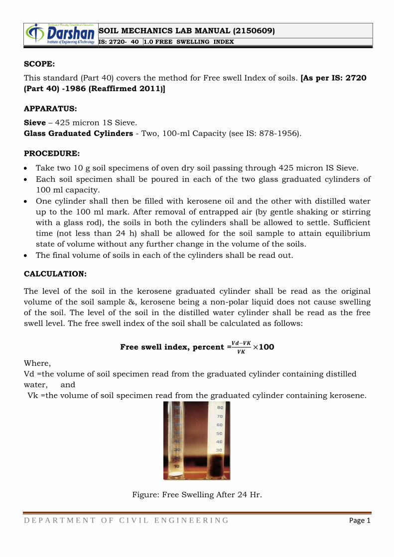
The level of the soil in the kerosene graduated cylinder shall be read as the original
volume of the soil sample &, kerosene being a non-polar liquid does not cause swelling
of the soil. The level of the soil in the distilled water cylinder shall be read as the free
swell level. The free swell index of the soil shall be calculated as follows:
Free swell index, percent =𝑽𝒅−𝑽𝑲
𝑽𝑲×100
Where,
Vd =the volume of soil specimen read from the graduated cylinder containing distilled
water, and
Vk =the volume of soil specimen read from the graduated cylinder containing kerosene.
Figure: Free Swelling After 24 Hr.
SOIL MECHANICS LAB MANUAL (2150609)
IS: 2720- 40 1.0 FREE SWELLING INDEX
D E P A R T M E N T O F C I V I L E N G I N E E R I N G Page 2
Value of free swelling index =
Conclusion:
Signature:
SOIL MECHANICS LAB MANUAL (2150609)
IS: 2720 -7&8 2.0 LIGHT/HEAVY COMPACTION TEST (PROCTOR TEST)
D E P A R T M E N T O F C I V I L E N G I N E E R I N G Page 3
OBJECT:
Determination of the relation between the water content and the dry density of soils
using light/heavy compaction.[As per IS: 2720 (Part 7&8) -1980] (Reaffirmed 1987)
APPARATUS:
Sample Extruder (Optional)
Container Tray or pan Balances
Oven Trowel and spatula Spoon 10 kg sensitive to 1 g and other of capacity 200 g sensitive to 0.01 g
Steel Straightedge - Mixing Tools
Metal Rammer Mould
A representative portion of air-dried soil material about 5 kg of material passing a 4.75-
mm IS Sieve shall be taken.
PROCEDURE:
Obtain a sufficient quantity of air-dried soil and pulverize it. Take about 5 kg of soil
passing through 4.75 mm sieve in a mixing tray.
Weigh the mould with base plate and apply grease lightly on the interior surfaces. Fit
the collar and place the mould on a solid base.
Add water to the soil to bring its moisture content to about 8% and then mix it
thoroughly using the trowel until the soil gets a uniform color.
For light compaction, compact the moist soil in three equal layers using a rammer of
mass 2.6 kg and having free fall of 31 cm. Distribute the blows evenly, and apply 25
blows in each layer. Ensure that the last compacted layer extends above the collar
joint. Alternatively for heavy compaction, compact the soil with 25 blows per layer,
in five equal layers with a rammer of mass 4.9 kg and 45 cm free fall.
Rotate the collar so as to remove it, trim off the compacted soil flush with the top of
the mould, and weigh the mould with soil and base plate.
Extrude the soil from the mould and collect soil samples from the top, middle and
bottom parts for water content determination. Place the soil back in the tray, add 2%
more water based on the original soil mass, and re-mix as in step 3. Repeat steps 4
and 5 until a peak value of compacted soil mass is reached followed by a few samples
of lesser compacted soil masses.
Calculate the bulk density of each compacted soil specimen.
Calculate the average moisture content of the compacted specimen and then its dry
density.
Plot the dry densities obtained as ordinates against the corresponding moisture
contents as abscissa, draw a smooth compaction curve passing through them, and
obtain the values of maximum dry density (MDD) and optimum moisture content
(OMC).
SOIL MECHANICS LAB MANUAL (2150609)
IS: 2720 -7&8 2.0 LIGHT/HEAVY COMPACTION TEST (PROCTOR TEST)
D E P A R T M E N T O F C I V I L E N G I N E E R I N G Page 4
On the same graph, plot a curve corresponding to 100% saturation, calculated from
Where,
S = degree of saturation,
Gs = specific gravity of solids, and
Ƴw = unit weight of water. CALCULATIONS:
Bulk Density –γb in g/ml, of each compacted specimen shall be calculated from the equation:
Ƴ𝐛 =𝐌𝟐 −𝐌𝟏
𝐕𝐦
Where,
Ml = mass in g of mould and base;
M2 = mass in g of mould, base and soil; and
Vm = volume in cm3 of mould.
The dry density, γdin g/cc, shall be calculated from the equation:
Ƴ𝒅 =𝟏𝟎𝟎 Ƴ𝒃
𝟏𝟎𝟎 + 𝐰
Where,
w = water content of soil in percent.
γb= Bulk Density g/cc
γd= Dry Density g/cc
The dry densities, 𝛾𝑏 obtained in a series of determinations shall be plotted against the
corresponding moisture contents w (%). A smooth curve shall be drawn through the
resulting points and the position of the maximum on this curve shall be determined.
SOIL MECHANICS LAB MANUAL (2150609)
IS: 2720 -7&8 2.0 LIGHT/HEAVY COMPACTION TEST (PROCTOR TEST)
D E P A R T M E N T O F C I V I L E N G I N E E R I N G Page 5
REPORTING OF RESULTS:
The dry density in g/cc corresponding to the maximum point on the moisture
content/ dry density curve shall be reported as the maximum dry density to the
nearest 0.01.
DETERMINATION OF WATER CONTENT – DRY DENSITY RELATION USING
LIGHT/HEAVY COMPACTION
COMPACTION TEST (PROCTOR TEST) [IS:2720-PART 7&8 – 1980, RA 1987]
Type of test (Standard/ Modified proctor test)
Volume of mould (cm3) (1000cm3/2250cm3)
TEST 1 2 3 4 5
Container no.
Empty weight of container
Container + wet soil(gm)
Container+ dry soil (gm)
Mass of mould(gm)
Mass of mould + compacted soil (gm)
Mass of compacted soil, Wt.(gm)
Bulk density (g/cc)
Average water contentw (%)
Dry density (g/cc )
Dry density at 100% saturation (g/cc )
RESULT SUMMARY (after plotting a graph)
Maximum Dry Density……………gm/cc
Optimum Moisture Content……………%
SOIL MECHANICS LAB MANUAL (2150609)
IS: 2720 -7&8 2.0 LIGHT/HEAVY COMPACTION TEST (PROCTOR TEST)
D E P A R T M E N T O F C I V I L E N G I N E E R I N G Page 6
Conclusion:
Signature:
SOIL MECHANICS LAB MANUAL (2150609)
IS: 2720 - 13 3.0 DIRECT SHEAR TEST
D E P A R T M E N T O F C I V I L E N G I N E E R I N G Page 7
SCOPE:
Determination of shear strength of soil with a maximum particle size of 4.75 mm in
untrained, consolidated untrained and consolidated drained conditions [As per IS: 2720
(Part 13) -1986 (Reaffirmed 2011)].
APPARATUS:
The shear box grid plates, porous stones, base plates, and loading pad and water jacket
shall conform to IS: 11229-1985.
The apparatus required for the test is as follows:
1. Loading Frame, Proving Ring - Force measuring of suitable capacity, fitted with a
dial-gauge accurate to 0.002 mm to measure the shear force.
2. Micrometer Dial Gauges – Accurate to 0.01 mm. One suitably mounted to measure
horizontal movement and the other suitably mounted to measure the vertical
compression of the specimen.
3. Sample Trimmer or Core Cutter, Stop Clock, Balance - Balance of I kg capacity
sensitive to 0.1 g.
PREPARATION OF SPECIMEN:
Undisturbed Specimens - Specimens of required size shall be prepared in accordance
with IS: 2720 (Part I)-1983.
Remolded Specimens
a. Cohesive soils may be compacted to the required density and moisture content, the
sample extracted and then trimmed to required size. Alternatively, the soil may be
compacted to the required density and moisture content directly into the shear box
after fixing the two halves of the shear box together by means of the fixing screws.
b. Cohesion less soils may be tamped in the shear box itself with the base plate and grid
plate or porous stone as required in place at the bottom of the box.
The cut specimen shall be weighed and trimmings obtained during cutting shall be used
to obtain the moisture content. Using this information, the bulk dry density of the
specimen in the shear box shall be determined.
SOIL MECHANICS LAB MANUAL (2150609)
IS: 2720 - 13 3.0 DIRECT SHEAR TEST
D E P A R T M E N T O F C I V I L E N G I N E E R I N G Page 8
PROCEDURE:
Undrained Test -The shear box with the specimen, plain grid plate over the base plate
at the bottom of the specimen and plain grid plate at the top of the specimen should be
fitted into position in the load frame.
The serrations of the grid plates should be at right angles to the direction of shear the
loading pad should be placed on the top grid plate. The water jacket should be
provided so that the sample does not get dried during the test.
The required normal stress should be applied and the rate of longitudinal
displacement/shear stress application so adjusted that no drainage can occur in the
sample during the test. The upper part of the shear box should be raised such that a
gap of about I mm is left between the two parts of the box.
The test may now be conducted by applying horizontal shear load to failure or to 20
percent longitudinal displacement, whichever occurs first. The shear load readings
indicated by the proving ring assembly and the corresponding longitudinal
displacements should be noted at regular intervals.
CALCULATIONS AND REPORT:
If necessary, the vertical compression, if any, of the soil specimen may be measured to
serve as check to ensure that drainage has not taken place from the soil specimen. At
the end of the test, the specimen should be removed from the box and the final moisture
content measured. A minimum of three (preferably four) tests shall be made on separate
specimens of the same density.
From the calibration chart of the proving ring, the loads corresponding to the load dial
readings obtained during the test should be calculated.
The loads so obtained divided by the corrected cross-sectional area of the specimen gives
the shear stress in the sample. The corrected cross-sectional area shall be calculated
from the following equation:
Corrected area = Ao (𝟏 − 𝜹
𝟑 )
Where, Ao = initial area of the specimen in cm2, and
𝛿 = displacement in cm.
SOIL MECHANICS LAB MANUAL (2150609)
IS: 2720 - 13 3.0 DIRECT SHEAR TEST
D E P A R T M E N T O F C I V I L E N G I N E E R I N G Page 9
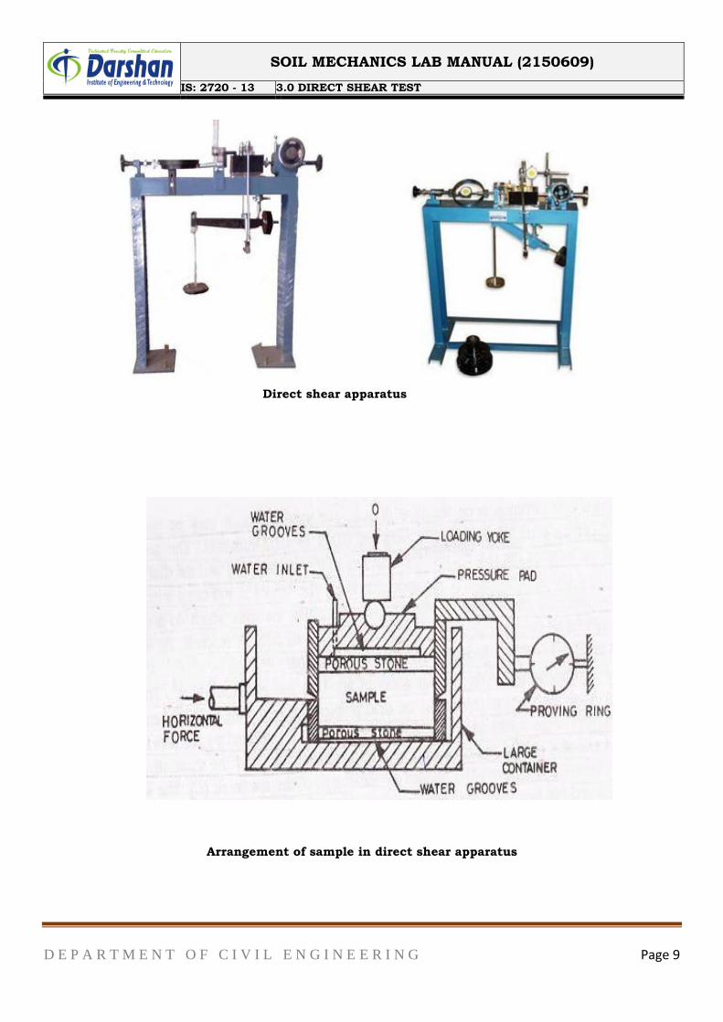
Direct shear apparatus
Arrangement of sample in direct shear apparatus
SOIL MECHANICS LAB MANUAL (2150609)
IS: 2720 - 13 3.0 DIRECT SHEAR TEST
D E P A R T M E N T O F C I V I L E N G I N E E R I N G Page 10
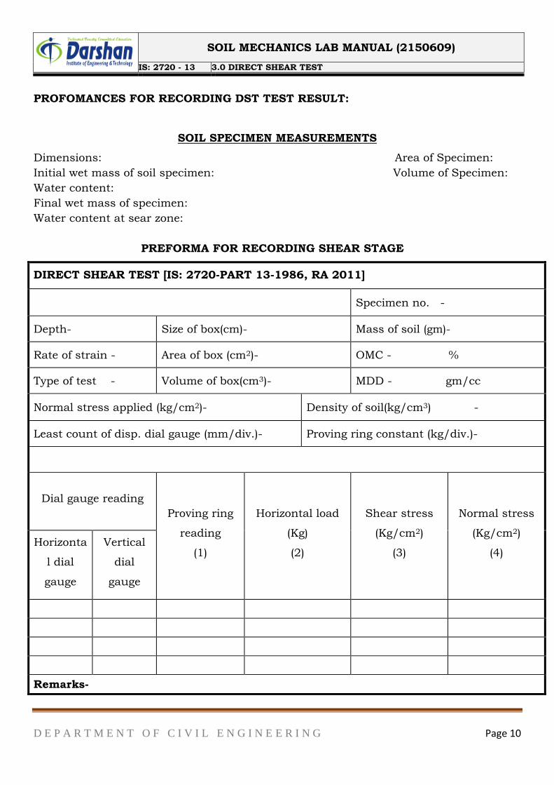
PROFOMANCES FOR RECORDING DST TEST RESULT:
SOIL SPECIMEN MEASUREMENTS
Dimensions: Area of Specimen:
Initial wet mass of soil specimen: Volume of Specimen:
Water content:
Final wet mass of specimen:
Water content at sear zone:
PREFORMA FOR RECORDING SHEAR STAGE
DIRECT SHEAR TEST [IS: 2720-PART 13-1986, RA 2011]
Specimen no. -
Depth- Size of box(cm)- Mass of soil (gm)-
Rate of strain - Area of box (cm2)- OMC - %
Type of test - Volume of box(cm3)- MDD - gm/cc
Normal stress applied (kg/cm2)- Density of soil(kg/cm3) -
Least count of disp. dial gauge (mm/div.)- Proving ring constant (kg/div.)-
Dial gauge reading
Proving ring
reading
(1)
Horizontal load
(Kg)
(2)
Shear stress
(Kg/cm2)
(3)
Normal stress
(Kg/cm2)
(4) Horizonta
l dial
gauge
Vertical
dial
gauge
Remarks-
SOIL MECHANICS LAB MANUAL (2150609)
IS: 2720 - 13 3.0 DIRECT SHEAR TEST
D E P A R T M E N T O F C I V I L E N G I N E E R I N G Page 11
From the graph
C = …………………….. Kg/cm2
Φ = ……………………... °
Conclusion:
Signature:
Shea
r st
ress
(kg
/cm
2)
Normal stress (kg/cm2)
BOX SHEAR TEST
SOIL MECHANICS LAB MANUAL (2150609)
IS: 2720 - 16 4.0 DETERMINATION OF CALIFORNIA BEARING RATIO OF SOIL
D E P A R T M E N T O F C I V I L E N G I N E E R I N G Page 12
SCOPE:
Determination of California Bearing Ratio (CBR) of undisturbed soil specimens obtained
from the field and also remoulded specimens of the soil compacted in the laboratory
both by the static and dynamic method, and in the soaked and unsoaked state.[As per
IS: 2720 (Part 16) -1987 (Reaffirmed 2011)].
APPARATUS/EQUIPMENT:
The apparatus required for the test is as follows:
1. Moulds with Base Plate, Stay Rod and Wing Nut -Spacer Disc Metal Rammer - As
specified in IS: 9198-1979.
2. Expansion Measuring Apparatus -.Weights - This shall conform to 4.4 of IS: 9669-
1989.
3. Loading Machine -Penetration Plunger - This shall conform to 4.4 of IS: 9669-1980.
To use a plunger of greater length, a suitable extension rod may be used.
4. Dial Gauges - Two dial gauges reading to 0.01 mm.
5. Sieves - 47.5-mm IS Sieve and 19-mm IS Sieve [see IS: 460 (Part 1)-1978].
Sieves - 47.5-mm IS Sieve and 19-mm IS Sieve [see IS: 460 (Part 1)-1978].
PREPARATION OF TEST SPECIMEN:
The test may be performed:
a) On undisturbed specimens, and
b) On remoulded specimens which may be compacted either statically or dynamically.
Soil Sample -The material used in the remoulded specimen shall pass a 19-mm IS
Sieve.
Allowance for larger material shall be made by replacing it by an equal amount of
material which passes a 19-mm IS Sieve but is retained on 4.75-mm IS Sieve.
Statically Compacted Specimens – The mass of the wet soil at the required moisture
content to give the desired density when occupying the standard specimen volume in the
mould shall be calculated, A batch of soil shall be thoroughly mixed with water to give
the required water content. The correct mass of the moist soils shall be placed in the
mould and compaction obtained by pressing in the displacer disc, a filter paper being
placed between the disc and the soil.
Dynamically Compacted Specimen – For dynamic compaction, a representative sample
of the soil weighing approximately 4.5 kg or more for fine-grained soils and 5.5 kg or
more for granular soils shall be taken and mixed thoroughly with water. If the soil is to
be compacted to the maximum dry-density at the optimum water content determined in
accordance with IS: 2720 (Part 7)-1980 or IS: 2720 (Part 8)-1983, the exact mass of soil
required shall be taken and the necessary quantity of water added so that the water
content of the soil sample is equal to the determined optimum water content.
SOIL MECHANICS LAB MANUAL (2150609)
IS: 2720 - 16 4.0 DETERMINATION OF CALIFORNIA BEARING RATIO OF SOIL
D E P A R T M E N T O F C I V I L E N G I N E E R I N G Page 13
PROCEDURE:
Test for Swelling:
A filter paper shall be placed over the specimen.
Weights to produce a surcharge equal to the weight of base material and pavement to
the nearest 2.5 kg shall be placed on the compact soil specimen.
The whole mould and weights shall be immersed in a tank of water allowing free
access of water to the top and bottom of the specimen.
The tripod for the expansion measuring device shall be mounted on the edge of the
mould and the initial dial gauge reading recorded.
This set-up shall be kept as such undisturbed for 96 hours.
Noting down the readings everyday against the time of reading.
A constant water level shall be maintained in the tank throughout the period.
At the end of the soaking period, the final reading of the dial gauge shall be noted, the
tripod removed and the mould taken out of the water tank.
The free water collected in the mould shall be removed and the specimen allowed
draining downward for 15 minutes. Care shall be taken not to disturb the surface of
the specimen during the removal of the water.
The weights, the perforated plate and the top filter paper shall be removed and the
mould with the soaked soil sample shall be weighed and the mass recorded.
PENETRATION TEST:
The mould, containing the specimen, with the base plate in position, but the top face
exposed, shall be placed on the lower plate of the testing machine.
To prevent upheaval of soil into the hole of the surcharge weights, 2.5 kg annular
weight shall be placed on the soil surface prior to seating the penetration plunger
after which the remainder of the surcharge weights shall be placed.
The initial load applied to the plunger shall be considered as the zero load when
determining the load penetration relation.
Load shall be applied to the penetration plunger so that the penetration is
approximately 1.25 mm per minute. Reading of the load shall be taken at
penetrations of 0.0, 0.5, 1.0, 1.5, 2.0, 2.5, 4.0, 5.0, 7.5, 10.0 and 12.5 mm The
maximum load and penetration shall be recorded it if occurs for a penetration of less
than 12.5 mm.
About 20 to 50 g of soil shall be collected from the top 30 mm layer of the specimen
and the water content determined.
SOIL MECHANICS LAB MANUAL (2150609)
IS: 2720 - 16 4.0 DETERMINATION OF CALIFORNIA BEARING RATIO OF SOIL
D E P A R T M E N T O F C I V I L E N G I N E E R I N G Page 14
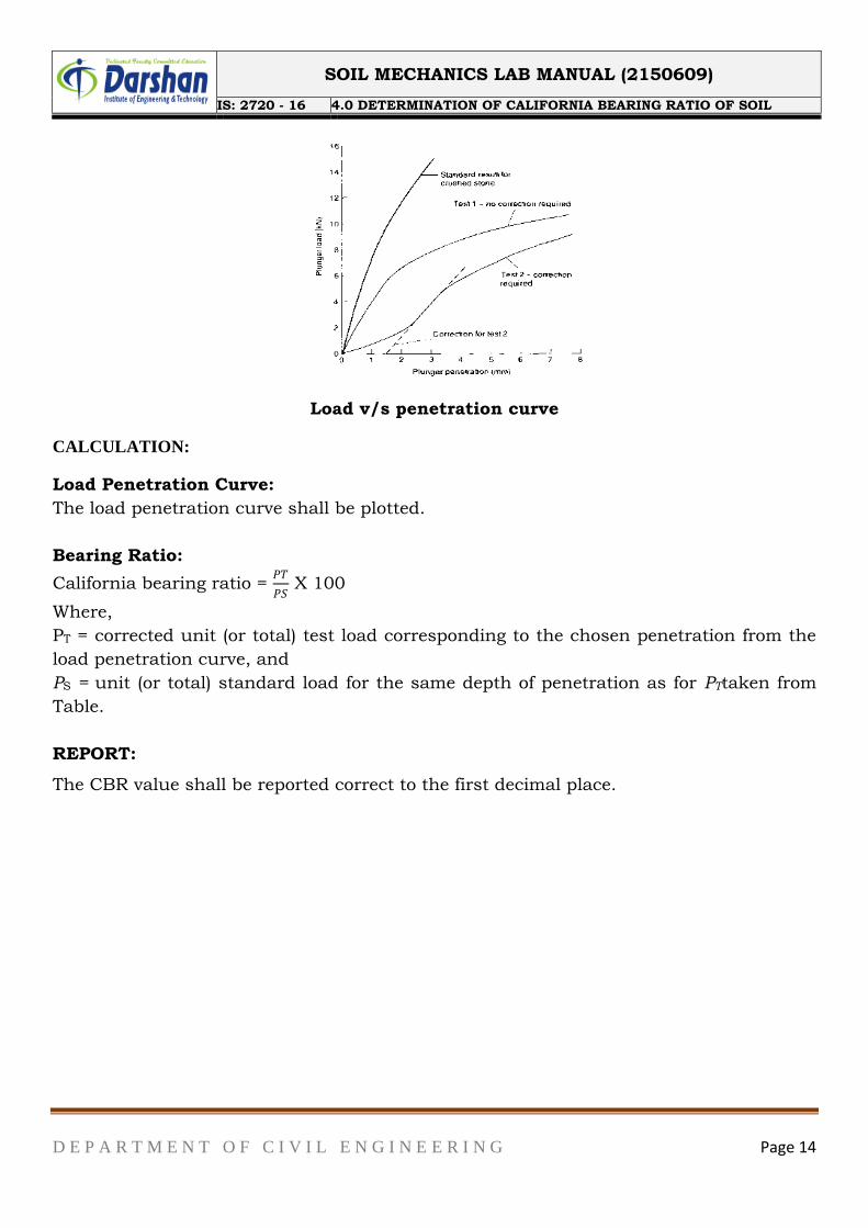
Load v/s penetration curve
CALCULATION:
Load Penetration Curve:
The load penetration curve shall be plotted.
Bearing Ratio:
California bearing ratio = 𝑃𝑇
𝑃𝑆 X 100
Where,
PT = corrected unit (or total) test load corresponding to the chosen penetration from the
load penetration curve, and
PS = unit (or total) standard load for the same depth of penetration as for PTtaken from
Table.
REPORT:
The CBR value shall be reported correct to the first decimal place.
SOIL MECHANICS LAB MANUAL (2150609)
IS: 2720 - 16 4.0 DETERMINATION OF CALIFORNIA BEARING RATIO OF SOIL
D E P A R T M E N T O F C I V I L E N G I N E E R I N G Page 15
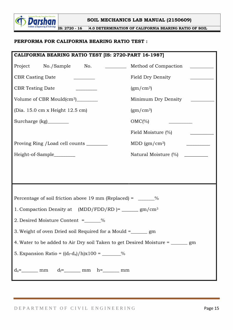
PERFORMA FOR CALIFORNIA BEARING RATIO TEST :
CALIFORNIA BEARING RATIO TEST [IS: 2720-PART 16-1987] Project No./Sample No. _________
CBR Casting Date _________
CBR Testing Date _________
Volume of CBR Mould(cm3)_________
(Dia. 15.0 cm x Height 12.5 cm)
Surcharge (kg)_________
Proving Ring /Load cell counts _________
Height-of-Sample_________
Method of Compaction __________
Field Dry Density __________
(gm/cm3)
Minimum Dry Density __________
(gm/cm3)
OMC(%) __________
Field Moisture (%) __________
MDD (gm/cm3) __________
Natural Moisture (%) __________
Percentage of soil friction above 19 mm (Replaced) = _______%
1. Compaction Density at (MDD/FDD/RD )= _______ gm/cm3
2. Desired Moisture Content =_______%
3. Weight of oven Dried soil Required for a Mould =_______ gm
4. Water to be added to Air Dry soil Taken to get Desired Moisture = _______ gm
5. Expansion Ratio = ((df-ds)/h)x100 = ________%
ds=_______ mm df=_______ mm h=_______ mm
SOIL MECHANICS LAB MANUAL (2150609)
IS: 2720 - 16 4.0 DETERMINATION OF CALIFORNIA BEARING RATIO OF SOIL
D E P A R T M E N T O F C I V I L E N G I N E E R I N G Page 16
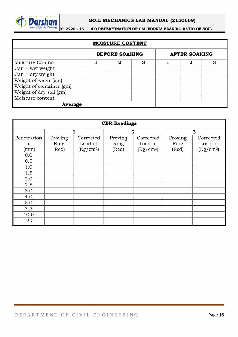
MOISTURE CONTENT
BEFORE SOAKING AFTER SOAKING
Moisture Can no 1 2 3 1 2 3
Can + wet weight
Can + dry weight
Weight of water (gm)
Weight of container (gm)
Weight of dry soil (gm)
Moisture content
Average
CBR Readings
1 2 3
Penetration in
(mm)
Proving Ring (Red)
Corrected Load in
(Kg/cm2)
Proving Ring (Red)
Corrected Load in
(Kg/cm2)
Proving Ring (Red)
Corrected Load in
(Kg/cm2)
0.0
0.5
1.0
1.5
2.0
2.5
3.0
4.0
5.0
7.5
10.0
12.5
SOIL MECHANICS LAB MANUAL (2150609)
IS: 2720 - 16 4.0 DETERMINATION OF CALIFORNIA BEARING RATIO OF SOIL
D E P A R T M E N T O F C I V I L E N G I N E E R I N G Page 17
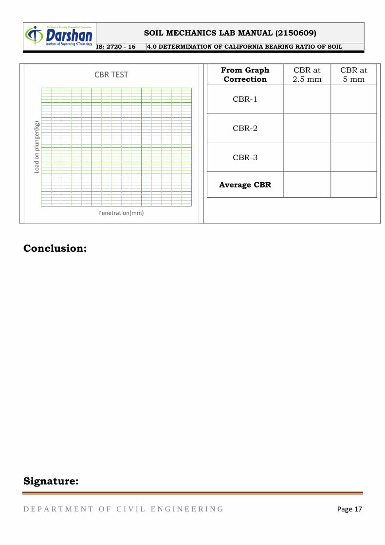
From Graph
Correction CBR at 2.5 mm
CBR at 5 mm
CBR-1
CBR-2
CBR-3
Average CBR
Conclusion:
Signature:
Load
on
plu
nge
r(kg
)
Penetration(mm)
CBR TEST
SOIL MECHANICS LAB MANUAL (2150609)
IS: 2720 - 10 5.0 UNCONFINED COMPRESSIVE STRENGTH
D E P A R T M E N T O F C I V I L E N G I N E E R I N G Page 18
OBJECT AND SCOPE:
The object of the experiment is to determine the unconfined compressive strength of
clayey soil using controlled strain. The purpose of the test is to obtain a quantitative
value of compressive and shearing strength of soils in an untrained state. The test may
be performed on both undisturbed and remolded soil specimen.
MATERIALS AND EQUIPMENTS:
I. Compression device of any suitable type
II. Sample ejector
III. Strain measuring dial gauge with 0.01 mm graduations
IV. Stopwatch
V. Oven
VI. Balance
VII. Miscellaneous equipment, such as specimen trimming and curving tools,
remolding apparatus, moisture cans, etc.
VIII. Split moulds 3.5 cm diameter and 7 cm long (or 3.75 cm diameter and 7.5 cm
long)
TEST PROCEDURE
Preparation of Test Specimen
I. Undisturbed cylindrical specimen may be cut from the bigger undisturbed
sample obtained from the field. A wire saw may be used to trim the ends parallel
to each other. a lathe or trimmermaybeusedtotrimthespecimentocircularcross-
section.Alternatively, fieldsample may be obtained directly in a thin sampling
tube having the same internal diameter as the specimen to be tested. The split
mould is oiled lightly from inside and the sample is then pushed out of the tube
into the split mould. The split mould is opened carefully and sample taken is
out.
II. Remolded sample may be prepared by compacting the soil at the desired water
content and dry density in a bigger mould, and then cut by the sampling tube.
Alternatively, remoulded specimen may be prepared directly in the split mould.
SOIL MECHANICS LAB MANUAL (2150609)
IS: 2720 - 10 5.0 UNCONFINED COMPRESSIVE STRENGTH
D E P A R T M E N T O F C I V I L E N G I N E E R I N G Page 19
Compression Test
1. Measure the initial length and diameter of the specimen.
2. Put the specimen on the bottom plate of the loading device. Adjust the upper plate to
make contact with the specimen. Set the load dial gauge and the strain (compression)
dial gauge to zero.
3. Compress the specimen until cracks have definitely developed of the stress strain
curve is well past it speak or until a vertical deformation of 20 percent reached. Take
the load dial readings approximately at every 1 mm deformation of the specimen.
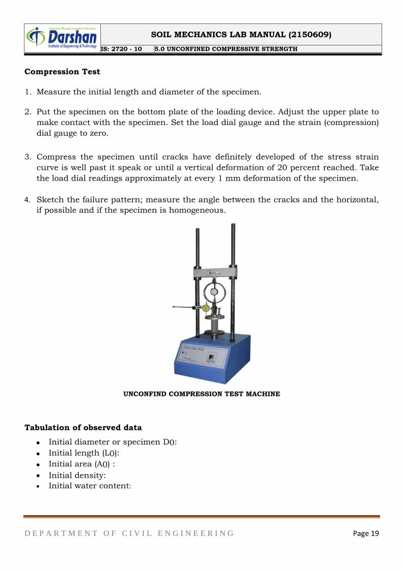
4. Sketch the failure pattern; measure the angle between the cracks and the horizontal,
if possible and if the specimen is homogeneous.
UNCONFIND COMPRESSION TEST MACHINE
Tabulation of observed data
Initial diameter or specimen D0:
Initial length (L0):
Initial area (A0) :
Initial density:
Initial water content:
SOIL MECHANICS LAB MANUAL (2150609)
IS: 2720 - 10 5.0 UNCONFINED COMPRESSIVE STRENGTH
D E P A R T M E N T O F C I V I L E N G I N E E R I N G Page 20
Determination of Unconfined Compressive Strength
Sr. No.
Elapsed time
(min.)
Load (Kg)
Deformation (cm)
Strain (%)
Area A
(cm2)
Stress (kg/cm2)
1
2
3
4
5
6
7
8
Calculation:
The axial strain ∈is determined by the following equation:
∈= ∆𝑳𝑳
Area = 𝑨𝟎
𝟏−∈
Where:
∆L = Change in specimen, as read from the strain dial.
L= Initial length of specimen.
Conclusion:
Signature:
SOIL MECHANICS LAB MANUAL (2150609)
IS: 2720 - 15 6.0 DETERMINATION OF CONSOLIDATION PARAMETERS
D E P A R T M E N T O F C I V I L E N G I N E E R I N G Page 21
OBJECT AND SCOPE:
To determine the compressibility i.e., consolidation characteristics of a soil by one
dimensional consolidation using consolidometer apparatus.
THEORY
Consolidation of soil is the process of compression by gradual reduction of pores under
a steady applied pressure. The main purpose of the consolidation test is to obtain soil
data required for predicting the rate and amount of settlement of structures. The data
can also be used to develop void ratio (e) versus pressure (p) curve generally for cohesive
soil.
The void ratio (e) of a soil specimen under any applied pressure (p) may be computed
using the following relationship, e=𝐻−𝐻𝑠
𝐻𝑠
Where,
H = Height of soil specimen at the end of each pressure increment (cm)
Hs = equivalent height of solids (cm), which is determined as follows:
Hs = 𝑊𝑠
𝐺×𝛾𝑤×𝐴
Where,
Ws= dry weight of the specimen
G = specific gravity of the solid particles
𝛾𝑤= unit weight of water (g/cc)
A = cross-sectional area of the soil specimen (cm2)
PREPARATION OF TEST SPECIMEN
1. UNDISTURBED SOIL SAMPLE
Clean, dry and lubricate the consolidation ring from inside with silicon
grease. Then weigh it. Record it as (W1) g.
Preparation from a block (undisturbed) sample
Sometimes, the soil sample from field is also collected as blocked mass. In that case,
cut a sample disc with two plain faces parallel to each other having its diameter and
thickness each at least 10mm greater than that of the consolidation ring. Hold the
consolidation ring vertically with cutting edge downwards and place it on the
prepared disc of the undisturbed soil sample. Using the ring as a template, trim off
SOIL MECHANICS LAB MANUAL (2150609)
IS: 2720 - 15 6.0 DETERMINATION OF CONSOLIDATION PARAMETERS
D E P A R T M E N T O F C I V I L E N G I N E E R I N G Page 22
the excess soil around the cutting edge. Gently, press the ring downwards with
minimum force required until the soil protrudes into the ring by about 5 mm above
its top. Cut the soil at the level of the-cutting edge of the cutter of the consolidation
ring. Trim the excess soil flush with top and bottom edges of the ring, using straight
edge. Remove the small interfering inclusion if any, during trimming process and fill
the cavity completely with the soil from the cuttings. Avoid the excessive remoulding
of the soil surfaces. Keep a portion from the trimmings/cuttings for determination of
initial moisture content and specific gravity. Weigh the ring with the specimen.
Record it as (W2)g.
PREPARATION FROM A TUBE SAMPLE
To push the sample directly into the consolidation ring, hold the ring firmly about 5
mm above the sample tube keeping the cutting face downwards. By means of a
hydraulic jack, eject the sample gently and steadily out of the tube so that it
introduces into the ring. During the process, continue trimming the specimen
carefully from outside the consolidation ring to reduce friction. Finally trim and
flush the soil sample with the ends of the consolidation ring.
2. REMOLDED SPECIMEN
Prepare the soil sample by compaction method in a compaction mould. The
compaction efforts (number of blows required for each layer) may be determined by
trial and error if the test is to be performed at desired moisture content and density,
other than optimum moisture content and maximum dry density. Place the
consolidation ring on a glass plate with the cutting edge upwards. Press the
remoulded soil into the ring by suitable means. Flush the soil specimen with the top
end of the ring and weigh. Alternatively the soil specimen may also be intruded into
the consolidation ring as explained.
Dynamically compacted specimen
Weigh the consolidation ring. Attach extension collar to the ring and place it on the
base plate. Prepare about 300 g wet soil for desired water content and density.
Calculate the volume of the ring including collar thickness (For a 60 mm dia. 30
mm total height (including 20 mm soil sample height), volume = 84.86 cm2) and the
required quantity of soil. Place this soil in the ring and compact by 2.6 kg rammer
or by any other suitable tool, to the total thickness including that of collar (30 mm).
Detach the extension collar and trim the excess soil flushing with the ring ends to
make the thickness of the specimen as 20 mm. Weigh the ring with compacted soil.
Statically compacted specimen
Prepare the soil specimen by mixing required quantity of water to about 300 g dry
SOIL MECHANICS LAB MANUAL (2150609)
IS: 2720 - 15 6.0 DETERMINATION OF CONSOLIDATION PARAMETERS
D E P A R T M E N T O F C I V I L E N G I N E E R I N G Page 23
soil. Leave the mix for about 5-6 hours. Keep a small quantity of this mix for
moisture content determination. Place the ring on the base plate and attach the
extension collar to it. Weigh the required quantity of the processed mix of wet soil to
obtain the desired test density when compressed to 84.86 cm2 volume. Place gently
the soil into the consolidation ring. Compress this apparatus by means of a suitable
pressing device. Detach the extension collar and trim the soil flushing with the edge
of the ring.
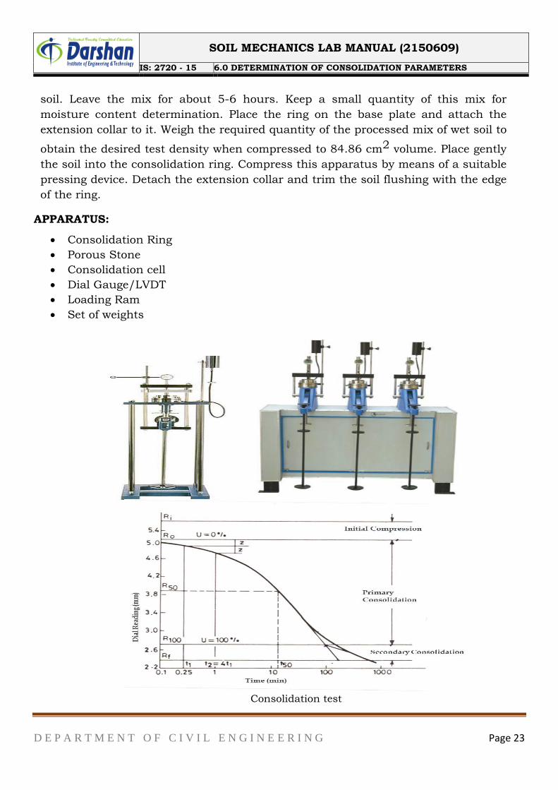
APPARATUS:
Consolidation Ring
Porous Stone
Consolidation cell
Dial Gauge/LVDT
Loading Ram
Set of weights
Consolidation test
SOIL MECHANICS LAB MANUAL (2150609)
IS: 2720 - 15 6.0 DETERMINATION OF CONSOLIDATION PARAMETERS
D E P A R T M E N T O F C I V I L E N G I N E E R I N G Page 24
PROCEDURE
Soak the porous stones in water and place the bottom porous stone on the base of
the consolidation cell. Keep a filter paper over the stone. Attach guide ring to one
or both ends of the consolidation ring containing soil specimen (as required) and
place it gently on the porous stone. Place another filter paper on the top of
specimen and keep upper porous stone and loading point. Adjust a steel ball in the
groove of the loading cap to provide uniform loading on the specimen.
Place this whole arrangement properly in position in the loading device. Check and
adjust the loading beam and the counter balancing system. Level the loading beam
with the help of a spirit level. Clamp the dial gauges in position for recording the
compression/swelling of the soil specimen. Read the initial dial reading and place a
0.05kg/cm2seating pressure on the pan of weight hanger. Connect the base plate
of the consolidation cell to water reservoir bymeans of rubber/plastic tubing for
saturating the soil specimen. Allow the saturation of the specimen for 24 hrs. Or
more to attain an almost constant dial gauge reading.
Select appropriate sequence of pressures to be applied. It is customary that the
pressure applied at any loading stage is twice that of the proceeding stage
pressure. The test, therefore, may be carried out for loading sequence, to apply
pressure on the soil specimen in the range of 0.125, 0.25, 0.5, 1.0, 2.0, 4.0, 8.0
and 16.0 kg/cm2. However some other combination of loads may also be taken as
per Table 8.1. The maximum pressure to be applied should be more than the
effective vertical pressure envisaged due to in-situ over burden and the proposed
structure to be constructed on that soil.
Take the dial gauge readings after application of each load according to a time
sequence i.e. total elapsed such as 0.25, 1.00, 2.25, 4, 6.25, 9, 12.25, 16, 20.25,
25, 36, 49, 64, 100, 144, 196, 225, 256 minutes and thereafter 24 hours. A period
of 24 hours is generally sufficient for completion of primary consolidation of the soil
specimen for a particular load. A longer time. May be required in case of hard soil.
i.e., soil containing clay particles 25% or (N) SPT values= 30 or qu i.e. unconfined
compressive strength> 4.0 kg/cm2). With the help of the above time sequence it is
easy to plot the specimen thickness against square root of time or logarithm of time.
If the object of the study is to obtain pressure-void ratio relationship only, the time
versus dial gauge readings may be avoided and record only the final dial gauge
reading for each load increment after 24hours.
After completing the dial gauge observations at maximum pressure, release the
applied pressure to zero (0.05 kg/cm'' seating pressure) and leave the soil specimen
to swell by water for 24 hours. Record the final reading of the dial gauge. If
SOIL MECHANICS LAB MANUAL (2150609)
IS: 2720 - 15 6.0 DETERMINATION OF CONSOLIDATION PARAMETERS
D E P A R T M E N T O F C I V I L E N G I N E E R I N G Page 25
required, the loads may be reduced in stages and time-swelling readings may also
be taken accordingly.
Remove the seating load (0.05 kg/cm') and dismantle the consolidation ring. Wipe
off water from the ring and remove filter papers from both the ends of the specimen.
Weigh the ring and record it as (W') g with the specimen and then place it in a
container and dry in an oven (105°- 110°C).Alternatively push the soil specimen out
of the ring carefully so that no soil particle is lost, weigh the specimen and dry.
After drying, weigh the ring with the specimen and record it as (W3) g. Determine
the specific gravity of the soil from the dried specimen. Place the porous stones in a
container filled with water and boil for about 20-30 minutes and then clean to
remove any soil particle therein for their further use.
OBSERVATION DATA
Details of Soil Sample
Measurements of container ring:
Diameter (interior) of container =
Area of container =
Initial thickness of soil sample =
Specific gravity of soils =
Equivalent height of solid, Hs =
Least count of Dial gauge =
Wet density =
Dry density =
SOIL MECHANICS LAB MANUAL (2150609)
IS: 2720 - 15 6.0 DETERMINATION OF CONSOLIDATION PARAMETERS
D E P A R T M E N T O F C I V I L E N G I N E E R I N G Page 26
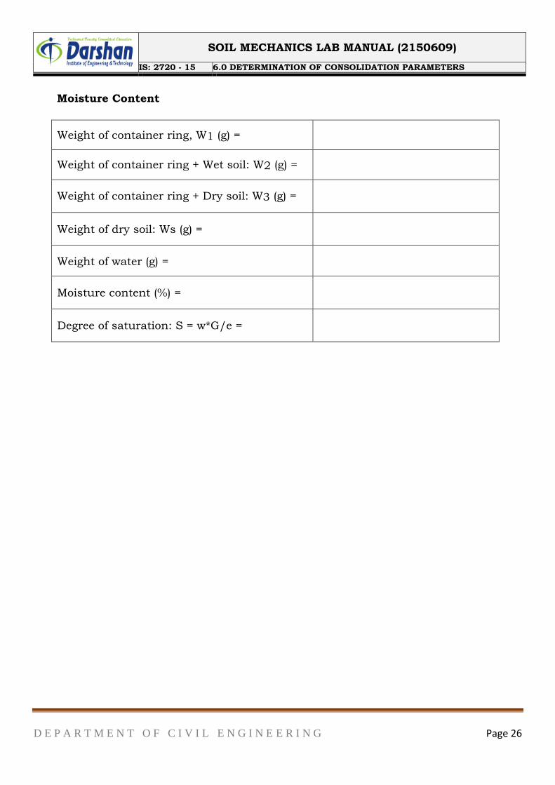
Moisture Content
Weight of container ring, W1 (g) =
Weight of container ring + Wet soil: W2 (g) =
Weight of container ring + Dry soil: W3 (g) =
Weight of dry soil: Ws (g) =
Weight of water (g) =
Moisture content (%) =
Degree of saturation: S = w*G/e =
SOIL MECHANICS LAB MANUAL (2150609)
IS: 2720 - 15 6.0 DETERMINATION OF CONSOLIDATION PARAMETERS
D E P A R T M E N T O F C I V I L E N G I N E E R I N G Page 27
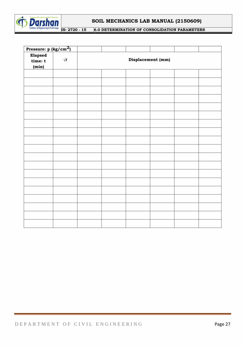
Pressure: p (kg/cm2)
Elapsed
time: t
(min)
√𝒕
Displacement (mm)
SOIL MECHANICS LAB MANUAL (2150609)
IS: 2720 - 15 6.0 DETERMINATION OF CONSOLIDATION PARAMETERS
D E P A R T M E N T O F C I V I L E N G I N E E R I N G Page 28
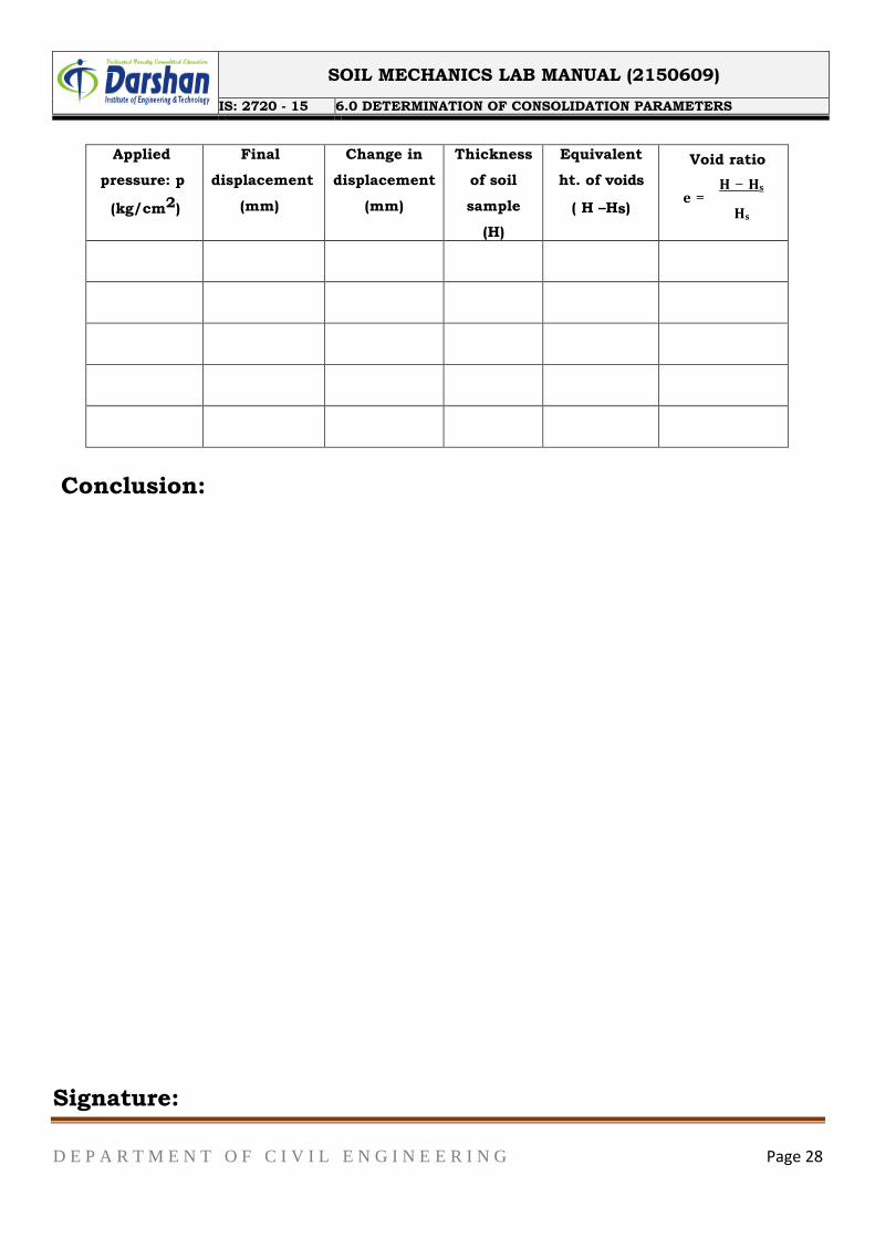
Applied
pressure: p
(kg/cm2)
Final
displacement
(mm)
Change in
displacement
(mm)
Thickness
of soil
sample
(H)
Equivalent
ht. of voids
( H –Hs)
Void ratio
𝐇 − 𝐇𝐬 𝐞 =
𝐇𝐬
Conclusion:
Signature:
SOIL MECHANICS LAB MANUAL (2150609)
IS: 2720 - 11 7.0 DETERMINATION OF SHEAR STRENTH PARAMETER BY TRIAXIAL TEST
D E P A R T M E N T O F C I V I L E N G I N E E R I N G Page 29
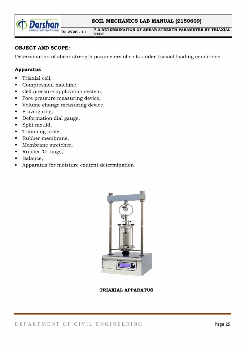
OBJECT AND SCOPE:
Determination of shear strength parameters of soils under triaxial loading conditions.
Apparatus
Triaxial cell,
Compression machine,
Cell pressure application system,
Pore pressure measuring device,
Volume change measuring device,
Proving ring,
Deformation dial gauge,
Split mould,
Trimming knife,
Rubber membrane,
Membrane stretcher,
Rubber „O' rings,
Balance,
Apparatus for moisture content determination
TRIAXIAL APPARATUS
SOIL MECHANICS LAB MANUAL (2150609)
IS: 2720 - 11 7.0 DETERMINATION OF SHEAR STRENTH PARAMETER BY TRIAXIAL TEST
D E P A R T M E N T O F C I V I L E N G I N E E R I N G Page 30
CU test
SOIL MECHANICS LAB MANUAL (2150609)
IS: 2720 - 11 7.0 DETERMINATION OF SHEAR STRENTH PARAMETER BY TRIAXIAL TEST
D E P A R T M E N T O F C I V I L E N G I N E E R I N G Page 31
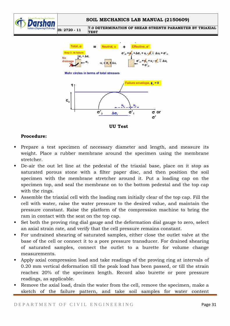
UU Test
Procedure:
Prepare a test specimen of necessary diameter and length, and measure its
weight. Place a rubber membrane around the specimen using the membrane
stretcher.
De-air the out let line at the pedestal of the triaxial base, place on it stop as
saturated porous stone with a filter paper disc, and then position the soil
specimen with the membrane stretcher around it. Put a loading cap on the
specimen top, and seal the membrane on to the bottom pedestal and the top cap
with the rings.
Assemble the triaxial cell with the loading ram initially clear of the top cap. Fill the
cell with water, raise the water pressure to the desired value, and maintain the
pressure constant. Raise the platform of the compression machine to bring the
ram in contact with the seat on the top cap.
Set both the proving ring dial gauge and the deformation dial gauge to zero, select
an axial strain rate, and verify that the cell pressure remains constant.
For undrained shearing of saturated samples, either close the outlet valve at the
base of the cell or connect it to a pore pressure transducer. For drained shearing
of saturated samples, connect the outlet to a burette for volume change
measurements.
Apply axial compression load and take readings of the proving ring at intervals of
0.20 mm vertical deformation till the peak load has been passed, or till the strain
reaches 20% of the specimen length. Record also burette or pore pressure
readings, as applicable.
Remove the axial load, drain the water from the cell, remove the specimen, make a
sketch of the failure pattern, and take soil samples for water content
SOIL MECHANICS LAB MANUAL (2150609)
IS: 2720 - 11 7.0 DETERMINATION OF SHEAR STRENTH PARAMETER BY TRIAXIAL TEST
D E P A R T M E N T O F C I V I L E N G I N E E R I N G Page 32
determination.
Repeat the test on identical soil specimens under different cell pressures.
Conclusion:
Signature:
SOIL MECHANICS LAB MANUAL (2150609)
ASTM D1452 8.0 AUGER BOARING /SAMPLING
D E P A R T M E N T O F C I V I L E N G I N E E R I N G Page 34
BORING METHODS OF EXPLORATION
The boring methods are used for exploration at greater depths where direct methods
fail. These provide both disturbed as well as undisturbed samples depending upon the
method of boring. In selecting the boring method for a particular job, consideration
should be made for the following:
The materials to be encountered and the relative efficiency of the various boring
methods in such materials
The available facility and accuracy with which changes in the soil and ground water
conditions can be determined
Possible disturbance of the material to be sampled The different types of boring
methods are:
Displacement boring
Wash boring
Auger boring
Rotary drilling
Percussion drilling
Continuous sampling
DISPLACEMENTBORING
It is combined method of sampling & boring operation. Closed bottom sampler, slit cup,
or piston type is forced in to the ground up to the desired depth. Then the sampler is
detached from soil below it, by rotating the piston, & finally the piston is released or
withdrawn. The sampler is then again forced further down & sample is taken. After
withdrawal of sampler & removal of sample from sampler, the sampler is kept in closed
condition & again used for another depth.
FEATURES
Simple and economic method if excessive caving does not occur. Therefore not
suitable for loose sand.
Major changes of soil character can be detected by means of penetration resistance.
These are 25mm to 75mmholes.
It requires fairly continuous sampling in stiff and dense soil, either to protect the
sampler from damage or to avoid objectionably heavy construction pit.
SOIL MECHANICS LAB MANUAL (2150609)
ASTM D1452 8.0 AUGER BOARING /SAMPLING
D E P A R T M E N T O F C I V I L E N G I N E E R I N G Page 35
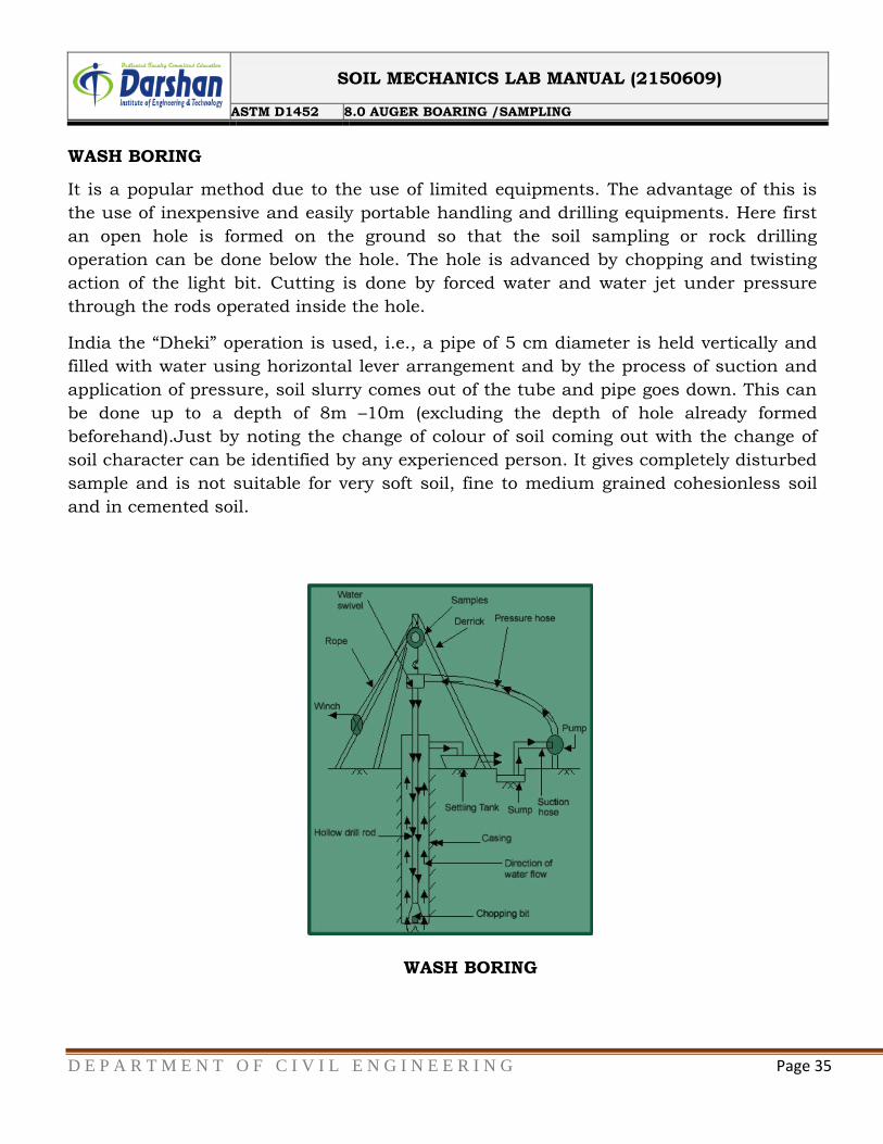
WASH BORING
It is a popular method due to the use of limited equipments. The advantage of this is
the use of inexpensive and easily portable handling and drilling equipments. Here first
an open hole is formed on the ground so that the soil sampling or rock drilling
operation can be done below the hole. The hole is advanced by chopping and twisting
action of the light bit. Cutting is done by forced water and water jet under pressure
through the rods operated inside the hole.
India the “Dheki” operation is used, i.e., a pipe of 5 cm diameter is held vertically and
filled with water using horizontal lever arrangement and by the process of suction and
application of pressure, soil slurry comes out of the tube and pipe goes down. This can
be done up to a depth of 8m –10m (excluding the depth of hole already formed
beforehand).Just by noting the change of colour of soil coming out with the change of
soil character can be identified by any experienced person. It gives completely disturbed
sample and is not suitable for very soft soil, fine to medium grained cohesionless soil
and in cemented soil.
WASH BORING
SOIL MECHANICS LAB MANUAL (2150609)
ASTM D1452 8.0 AUGER BOARING /SAMPLING
D E P A R T M E N T O F C I V I L E N G I N E E R I N G Page 36
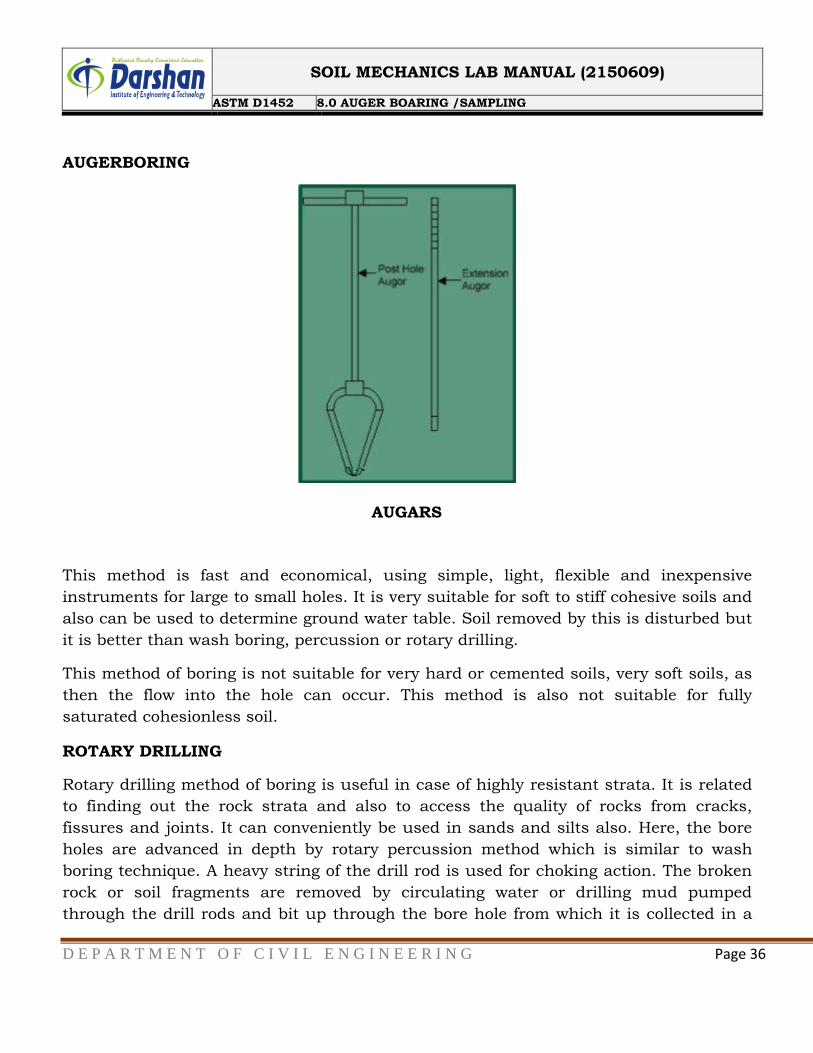
AUGERBORING
AUGARS
This method is fast and economical, using simple, light, flexible and inexpensive
instruments for large to small holes. It is very suitable for soft to stiff cohesive soils and
also can be used to determine ground water table. Soil removed by this is disturbed but
it is better than wash boring, percussion or rotary drilling.
This method of boring is not suitable for very hard or cemented soils, very soft soils, as
then the flow into the hole can occur. This method is also not suitable for fully
saturated cohesionless soil.
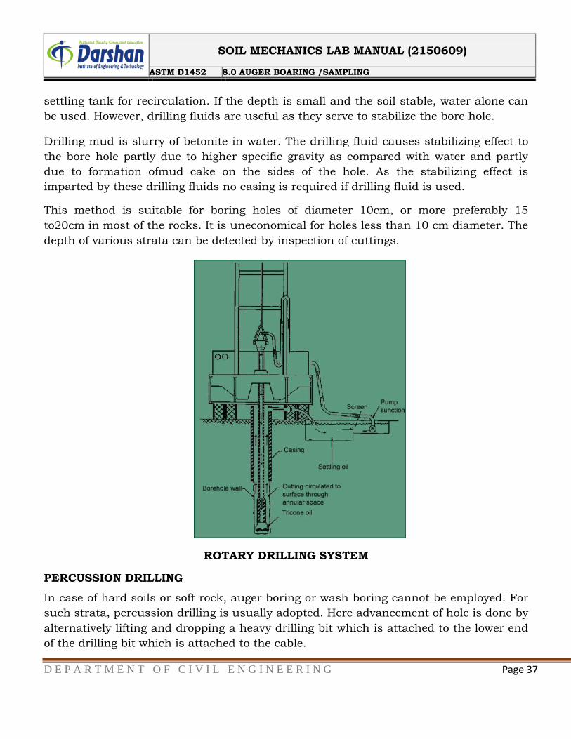
ROTARY DRILLING
Rotary drilling method of boring is useful in case of highly resistant strata. It is related
to finding out the rock strata and also to access the quality of rocks from cracks,
fissures and joints. It can conveniently be used in sands and silts also. Here, the bore
holes are advanced in depth by rotary percussion method which is similar to wash
boring technique. A heavy string of the drill rod is used for choking action. The broken
rock or soil fragments are removed by circulating water or drilling mud pumped
through the drill rods and bit up through the bore hole from which it is collected in a
SOIL MECHANICS LAB MANUAL (2150609)
ASTM D1452 8.0 AUGER BOARING /SAMPLING
D E P A R T M E N T O F C I V I L E N G I N E E R I N G Page 37
settling tank for recirculation. If the depth is small and the soil stable, water alone can
be used. However, drilling fluids are useful as they serve to stabilize the bore hole.
Drilling mud is slurry of betonite in water. The drilling fluid causes stabilizing effect to
the bore hole partly due to higher specific gravity as compared with water and partly
due to formation ofmud cake on the sides of the hole. As the stabilizing effect is
imparted by these drilling fluids no casing is required if drilling fluid is used.
This method is suitable for boring holes of diameter 10cm, or more preferably 15
to20cm in most of the rocks. It is uneconomical for holes less than 10 cm diameter. The
depth of various strata can be detected by inspection of cuttings.
ROTARY DRILLING SYSTEM
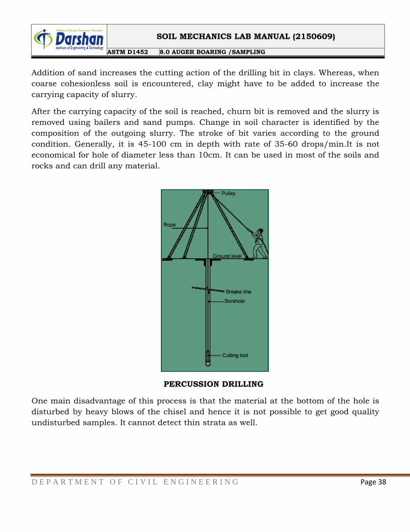
PERCUSSION DRILLING
In case of hard soils or soft rock, auger boring or wash boring cannot be employed. For
such strata, percussion drilling is usually adopted. Here advancement of hole is done by
alternatively lifting and dropping a heavy drilling bit which is attached to the lower end
of the drilling bit which is attached to the cable.
SOIL MECHANICS LAB MANUAL (2150609)
ASTM D1452 8.0 AUGER BOARING /SAMPLING
D E P A R T M E N T O F C I V I L E N G I N E E R I N G Page 38
Addition of sand increases the cutting action of the drilling bit in clays. Whereas, when
coarse cohesionless soil is encountered, clay might have to be added to increase the
carrying capacity of slurry.
After the carrying capacity of the soil is reached, churn bit is removed and the slurry is
removed using bailers and sand pumps. Change in soil character is identified by the
composition of the outgoing slurry. The stroke of bit varies according to the ground
condition. Generally, it is 45-100 cm in depth with rate of 35-60 drops/min.It is not
economical for hole of diameter less than 10cm. It can be used in most of the soils and
rocks and can drill any material.
PERCUSSION DRILLING
One main disadvantage of this process is that the material at the bottom of the hole is
disturbed by heavy blows of the chisel and hence it is not possible to get good quality
undisturbed samples. It cannot detect thin strata as well.
SOIL MECHANICS LAB MANUAL (2150609)
ASTM D1452 8.0 AUGER BOARING /SAMPLING
D E P A R T M E N T O F C I V I L E N G I N E E R I N G Page 39
CONTINUOUS SAMPLING
The sampling operation advances the borehole and the boring is accomplished entirely
by taking samples continuously. The casing is used to prevent the caving in soils. It
provides more reliable and detail information on soil condition than the other methods.
Therefore it is used extensively in detailed and special foundation exploration for
important structures.
It is slower method and more expensive than intermittent sampling. When modern
rotary drilling rigs or power driven augers are not available, continuous sampling may
be used to advantage for advancing larger diameter borings in stiff and tough strata of
clay and mixed soil.
In the Boston district, corps of Engineers has made faster progress and reduced cost by
use of continuous sampling in advancing 3-inch diameter borings through compact
gravelly glacial till, which is difficult to penetrate by any boring method.
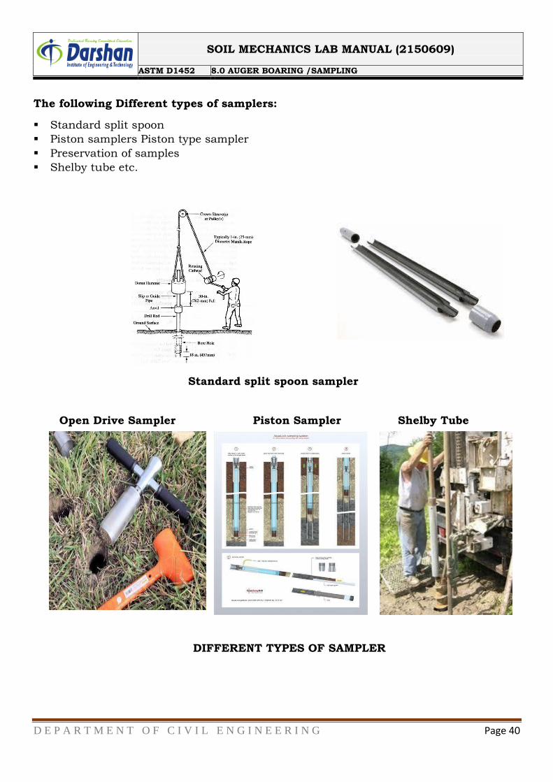
SOIL SAMPLINGS AND SAMPLERS
Soil Sampling In general soil samples are categorized in to 2 types of samples.
Disturbed samples: The structure of the soil is disturbed to the considerable degree by
the action of the boring tools or the excavation equipments.
The disturbances can be classified in following basic types :Change in the stress
condition, Change in the water content and the void ratio, Disturbance of the soil
structure, Chemical changes, Mixing and segregation of soil constituents The causes of
the disturbances are listed below: Method of advancing the bore hole, Mechanism used
to advance the sampler, Dimension and type of sampler, Procedure followed in
sampling and boring. If all the constituents are present in the sample which represents
the same soil type from any place, then it is called a representative sample. In the
remolded sample the engineering properties get changed due to remoulding
Undisturbed samples: It retains as closely as practicable the true in-situ structure and
water content of the soil. For undisturbed sample the stress changes cannot be avoided.
No change due to disturbance of the soil structure, No change in void ratio and water
content, No change in constituents.
SOIL MECHANICS LAB MANUAL (2150609)
ASTM D1452 8.0 AUGER BOARING /SAMPLING
D E P A R T M E N T O F C I V I L E N G I N E E R I N G Page 40