Page 1
1VD.KD.D6.02 © Danfoss 12/2014DEN-SMT/SI
Standard JIP™ ball valves (PN 16, 25, 40)Data sheet
Description
Main data:• DN 15-600• kVS = 11-26.300 m3/h• PN 16 / 25 / 40• Temperature: 0 ... 180 °C• Medium: Circulation water / glycolic water up
to 50 %• Min. storage and transport temperature: −40 °C
Approvals and norms:• 100 % final inspection. Leak and shell test as
well as dimension and functionality test is performed on each and every valve according to applicable standard (EN 12266 part 1 P10-P11-P12 & part 2 F20).
• PED Directive 97/23/EEC Modul H1• Danfoss A/S is certified according to ISO 9001• Furthermore certified according to ISO 14001
and OHSAS 18001.
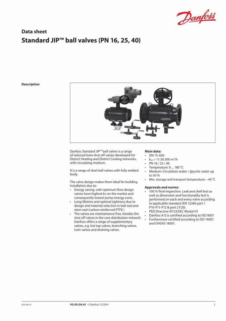
Danfoss Standard JIP™ ball valves is a range of reduced bore shut off valves developed for District Heating and District Cooling networks, with circulating medium.
It is a range of steel ball valves with fully welded body.
The valve design makes them ideal for building installation due to:• Energy saving: with optimum flow design
valves have highest kv on the market and consequently lowest pump energy costs.
• Long lifetime and optimal tightness due to design and material selection in ball seal and stem seal (carbon reinforced PTFE) ;
• The valves are maintainance free, besides the shut off valves in the core distribution network Danfoss offers a range of supplementary valves, e.g. hot tap valves, branching valves, twin valves and draining valves.
Page 2
2 VD.KD.D6.02 © Danfoss 12/2014 DEN-SMT/SI
Data sheet Standard JIP™ ball valves
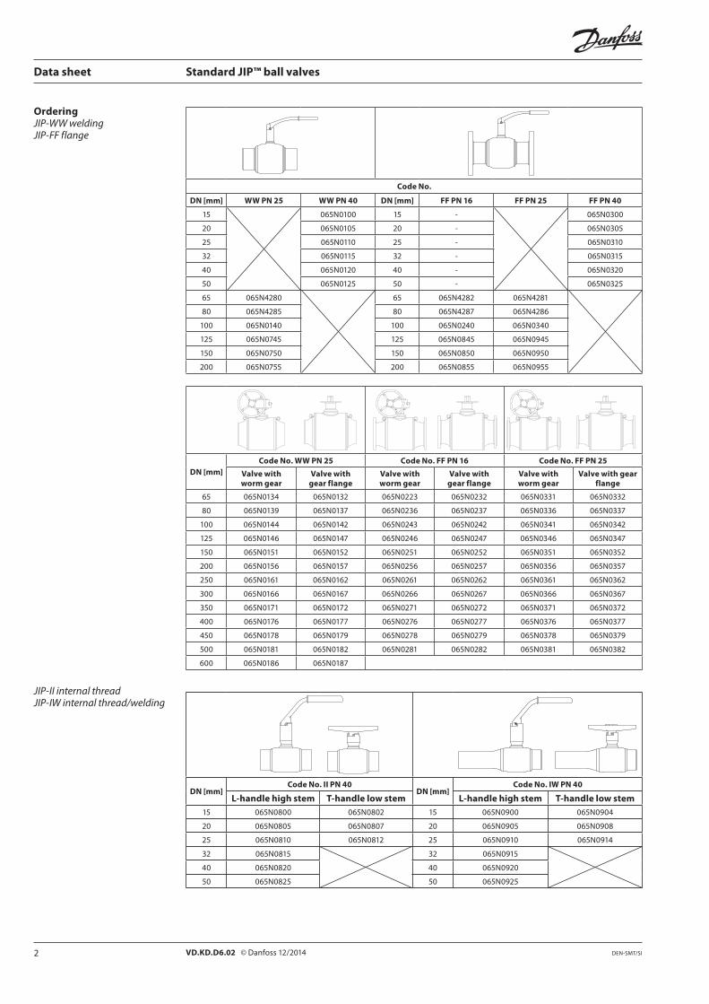
OrderingJIP-WW weldingJIP-FF flange
Code No.
DN [mm] WW PN 25 WW PN 40 DN [mm] FF PN 16 FF PN 25 FF PN 40
15 065N0100 15 - 065N0300
20 065N0105 20 - 065N0305
25 065N0110 25 - 065N0310
32 065N0115 32 - 065N0315
40 065N0120 40 - 065N0320
50 065N0125 50 - 065N0325
65 065N4280 65 065N4282 065N4281
80 065N4285 80 065N4287 065N4286
100 065N0140 100 065N0240 065N0340
125 065N0745 125 065N0845 065N0945
150 065N0750 150 065N0850 065N0950
200 065N0755 200 065N0855 065N0955
DN [mm]Code No. WW PN 25 Code No. FF PN 16 Code No. FF PN 25
Valve with worm gear
Valve with gear flange
Valve with worm gear
Valve with gear flange
Valve with worm gear
Valve with gear flange
65 065N0134 065N0132 065N0223 065N0232 065N0331 065N0332
80 065N0139 065N0137 065N0236 065N0237 065N0336 065N0337
100 065N0144 065N0142 065N0243 065N0242 065N0341 065N0342
125 065N0146 065N0147 065N0246 065N0247 065N0346 065N0347
150 065N0151 065N0152 065N0251 065N0252 065N0351 065N0352
200 065N0156 065N0157 065N0256 065N0257 065N0356 065N0357
250 065N0161 065N0162 065N0261 065N0262 065N0361 065N0362
300 065N0166 065N0167 065N0266 065N0267 065N0366 065N0367
350 065N0171 065N0172 065N0271 065N0272 065N0371 065N0372
400 065N0176 065N0177 065N0276 065N0277 065N0376 065N0377
450 065N0178 065N0179 065N0278 065N0279 065N0378 065N0379
500 065N0181 065N0182 065N0281 065N0282 065N0381 065N0382
600 065N0186 065N0187
JIP-II internal threadJIP-IW internal thread/welding
DN [mm]Code No. II PN 40
DN [mm]Code No. IW PN 40
L-handle high stem T-handle low stem L-handle high stem T-handle low stem15 065N0800 065N0802 15 065N0900 065N0904
20 065N0805 065N0807 20 065N0905 065N0908
25 065N0810 065N0812 25 065N0910 065N0914
32 065N0815 32 065N0915
40 065N0820 40 065N0920
50 065N0825 50 065N0925
Page 3
3VD.KD.D6.02 © Danfoss 12/2014DEN-SMT/SI
Data sheet Standard JIP™ ball valves
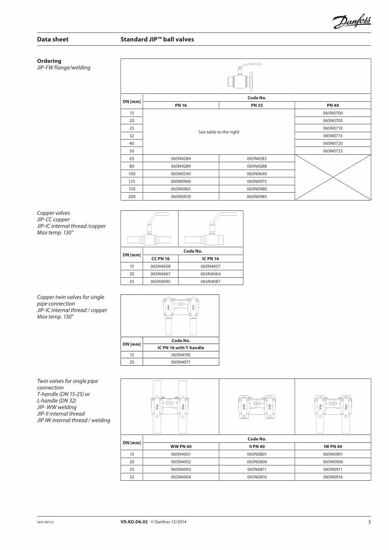
OrderingJIP-FW flange/welding
DN [mm]Code No.
PN 16 PN 25 PN 40
15
See table to the right
065N0700
20 065N0705
25 065N0710
32 065N0715
40 065N0720
50 065N0725
65 065N4284 065N4283
80 065N4289 065N4288
100 065N0540 065N0640
125 065N0960 065N0975
150 065N0965 065N0980
200 065N0970 065N0985
Copper valvesJIP-CC copperJIP-IC internal thread /copperMax temp. 130°
DN [mm]Code No.
CC PN 16 IC PN 16
15 065N4058 065N4057
20 065N4067 065N4064
25 065N4095 065N4087
Copper twin valves for single pipe connectionJIP-IC internal thread / copperMax temp. 130°
DN [mm]Code No.
IC PN 16 with T-handle
15 065N4195
20 065N4071
Twin valves for single pipe connection T-handle (DN 15-25) or L-handle (DN 32)JIP- WW weldingJIP-II internal threadJIP IW internal thread / welding
DN [mm]Code No.
WW PN 40 II PN 40 IW PN 40
15 065N4001 065N0801 065N0901
20 065N4002 065N0806 065N0906
25 065N4003 065N0811 065N0911
32 065N4004 065N0816 065N0916
Page 4
4 VD.KD.D6.02 © Danfoss 12/2014 DEN-SMT/SI
Data sheet Standard JIP™ ball valves
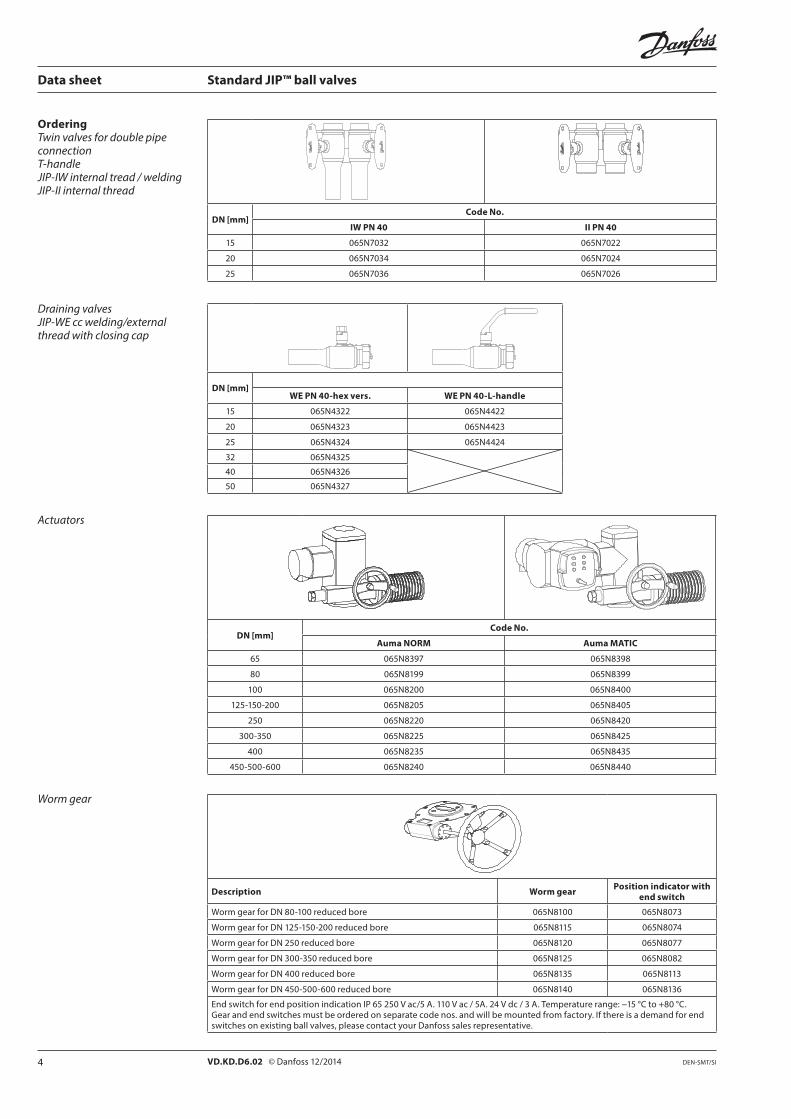
OrderingTwin valves for double pipe connectionT-handleJIP-IW internal tread / weldingJIP-II internal thread
DN [mm]Code No.
IW PN 40 II PN 40
15 065N7032 065N7022
20 065N7034 065N7024
25 065N7036 065N7026
Draining valvesJIP-WE cc welding/external thread with closing cap
DN [mm]WE PN 40-hex vers. WE PN 40-L-handle
15 065N4322 065N4422
20 065N4323 065N4423
25 065N4324 065N4424
32 065N4325
40 065N4326
50 065N4327
Actuators
DN [mm]Code No.
Auma NORM Auma MATIC
65 065N8397 065N8398
80 065N8199 065N8399
100 065N8200 065N8400
125-150-200 065N8205 065N8405
250 065N8220 065N8420
300-350 065N8225 065N8425
400 065N8235 065N8435
450-500-600 065N8240 065N8440
Worm gear
Description Worm gear Position indicator with end switch
Worm gear for DN 80-100 reduced bore 065N8100 065N8073
Worm gear for DN 125-150-200 reduced bore 065N8115 065N8074
Worm gear for DN 250 reduced bore 065N8120 065N8077
Worm gear for DN 300-350 reduced bore 065N8125 065N8082
Worm gear for DN 400 reduced bore 065N8135 065N8113
Worm gear for DN 450-500-600 reduced bore 065N8140 065N8136
End switch for end position indication IP 65 250 V ac/5 A. 110 V ac / 5A. 24 V dc / 3 A. Temperature range: −15 °C to +80 °C. Gear and end switches must be ordered on separate code nos. and will be mounted from factory. If there is a demand for end switches on existing ball valves, please contact your Danfoss sales representative.
Page 5
5VD.KD.D6.02 © Danfoss 12/2014DEN-SMT/SI
Data sheet Standard JIP™ ball valves
OrderingAccessories
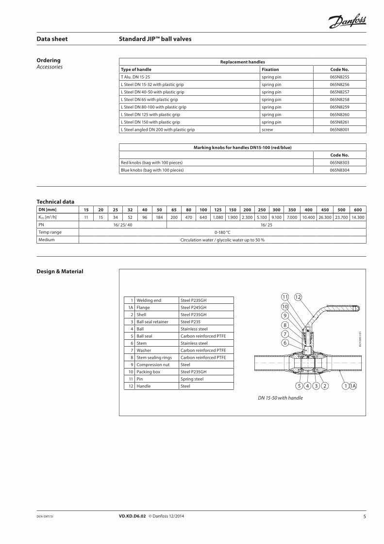
Replacement handles
Type of handle Fixation Code No.
T Alu. DN 15-25 spring pin 065N8255
L Steel DN 15-32 with plastic grip spring pin 065N8256
L Steel DN 40-50 with plastic grip spring pin 065N8257
L Steel DN 65 with plastic grip spring pin 065N8258
L Steel DN 80-100 with plastic grip spring pin 065N8259
L Steel DN 125 with plastic grip spring pin 065N8260
L Steel DN 150 with plastic grip spring pin 065N8261
L Steel angled DN 200 with plastic grip screw 065N8001
Marking knobs for handles DN15-100 (red/blue)
Code No.
Red knobs (bag with 100 pieces) 065N8303
Blue knobs (bag with 100 pieces) 065N8304
Technical dataDN [mm] 15 20 25 32 40 50 65 80 100 125 150 200 250 300 350 400 450 500 600
KVS [m3/h] 11 15 34 52 96 184 200 470 640 1.080 1.900 2.300 5.100 9.100 7.000 10.400 26.300 23.700 14.300
PN 16/ 25/ 40 16/ 25
Temp range 0-180 °C
Medium Circulation water / glycolic water up to 50 %
Design & Material
1 Welding end Steel P235GH
1A Flange Steel P245GH
2 Shell Steel P235GH
3 Ball seal retainer Steel P235
4 Ball Stainless steel
5 Ball seal Carbon reinforced PTFE
6 Stem Stainless steel
7 Washer Carbon reinforced PTFE
8 Stem sealing rings Carbon reinforced PTFE
9 Compression nut Steel
10 Packing box Steel P235GH
11 Pin Spring steel
12 Handle Steel
DN 15-50 with handle
Page 6
6 VD.KD.D6.02 © Danfoss 12/2014 DEN-SMT/SI
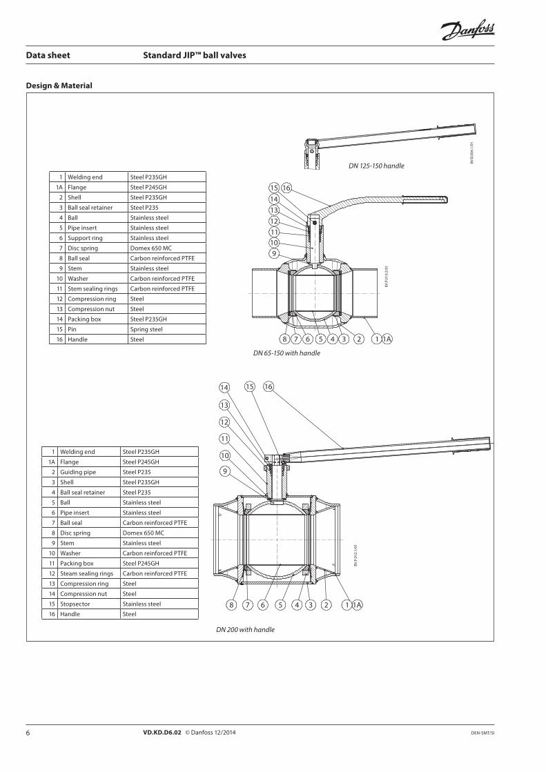
DN 125-150 handle
Design & Material
Data sheet Standard JIP™ ball valves
1 Welding end Steel P235GH
1A Flange Steel P245GH
2 Shell Steel P235GH
3 Ball seal retainer Steel P235
4 Ball Stainless steel
5 Pipe insert Stainless steel
6 Support ring Stainless steel
7 Disc spring Domex 650 MC
8 Ball seal Carbon reinforced PTFE
9 Stem Stainless steel
10 Washer Carbon reinforced PTFE
11 Stem sealing rings Carbon reinforced PTFE
12 Compression ring Steel
13 Compression nut Steel
14 Packing box Steel P235GH
15 Pin Spring steel
16 Handle Steel
1 Welding end Steel P235GH
1A Flange Steel P245GH
2 Guiding pipe Steel P235
3 Shell Steel P235GH
4 Ball seal retainer Steel P235
5 Ball Stainless steel
6 Pipe insert Stainless steel
7 Ball seal Carbon reinforced PTFE
8 Disc spring Domex 650 MC
9 Stem Stainless steel
10 Washer Carbon reinforced PTFE
11 Packing box Steel P245GH
12 Steam sealing rings Carbon reinforced PTFE
13 Compression ring Steel
14 Compression nut Steel
15 Stopsector Stainless steel
16 Handle Steel
DN 65-150 with handle
DN 200 with handle
Page 7
7VD.KD.D6.02 © Danfoss 12/2014DEN-SMT/SI
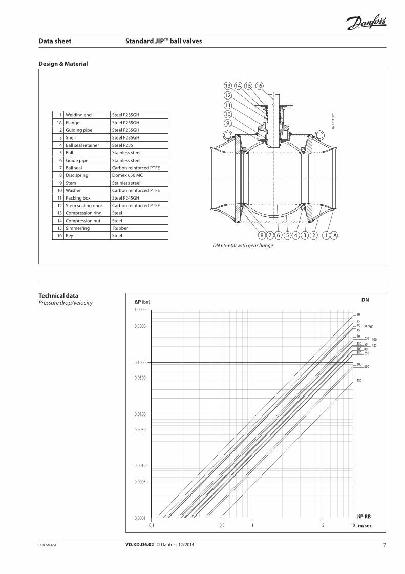
Design & Material
20
3265 25/600
200
50100125
1540
35080400250
500
150
300
450
1,0000
0,1000
0,0100
0,0010
0,00010,1 1 m/sec
DN
10
0,0005
0,0050
0,0500
0,5000
0,5 5
ΔP (bar)
JiP RB
Data sheet Standard JIP™ ball valves
Technical dataPressure drop/velocity
1 Welding end Steel P235GH
1A Flange Steel P235GH
2 Guiding pipe Steel P235GH
3 Shell Steel P235GH
4 Ball seal retainer Steel P235
5 Ball Stainless steel
6 Guide pipe Stainless steel
7 Ball seal Carbon reinforced PTFE
8 Disc spring Domex 650 MC
9 Stem Stainless steel
10 Washer Carbon reinforced PTFE
11 Packing box Steel P245GH
12 Stem sealing rings Carbon reinforced PTFE
13 Compression ring Steel
14 Compression nut Steel
15 Simmerring Rubber
16 Key Steel
DN 65-600 with gear flange
Page 8
8 VD.KD.D6.02 © Danfoss 12/2014 DEN-SMT/SI
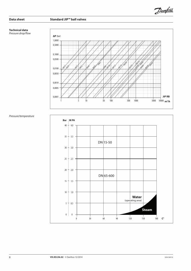
1 10 100 1000 10000 m3/h
1,0000
0,1000
0,0100
0,0010
0,0001
ΔP (bar)
JiP RB
5 50 500 5000
0,0005
0,0050
0,0500
0,5000
DN15DN20
DN25DN32
DN40
DN50
DN65
DN80DN100
DN125
DN150 DN200
DN250
DN350DN300 DN400DN600DN500 DN450
0 30 60 90 120 150 180 C°
Bar M PA
40 4,0
35 3,5
30 3,0
25 2,5
20 2,0
15 1,5
10 1,0
5 0,5
0 0
DN 15-50
DN 65-600
Steam
Water(operating area)
Data sheet Standard JIP™ ball valves
Technical dataPressure drop/flow
Pressure/temperature
Page 9
9VD.KD.D6.02 © Danfoss 12/2014DEN-SMT/SI
R
S
ØC
L
F
H
ØA
ØD
R
ØC
L
F H
ØA
ØD
T
S
ØC
L
F H
ØA
ØB
ØD
O
G1
G2
G3
E
L
FHh H
g
ØD ØB
ØA
ØC
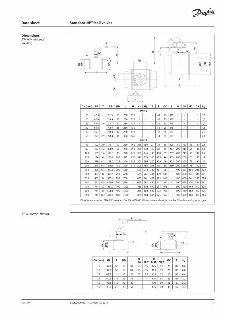
Data sheet Standard JIP™ ball valves
DN [mm] ØA T ØB ØD L H Hh Hg E F ØC S O G1 G2 G3 kg
PN 40
15 42,4
2,6
21,3 15 230 125 - - - 61 25 115 - - - - 1,0
20 42,4 26,9 15 230 125 - - - 58 25 115 - - - - 1,0
25 48,3 33,7 20 230 125 - - - 56 25 115 - - - - 1,2
32 60,3 42,4 25 260 130 - - - 56 25 115 - - - - 1,5
40 76,1 48,3 32 260 140 - - - 54 35 157 - - - - 2,3
50 76,1 2,9 60,3 40 300 145 - - - 54 35 157 - - - - 2,8
PN 25
65 102 2,9 76,1 50 260 160 255 150 97 73 35 205 150 163 63 137 3,8
80 127 3,2 88,9 65 270 190 288 138 110 88 39 257 200 215 56 140 5,6
100 159 3,6 114,3 80 290 225 301 146 145 108 39 257 200 215 56 140 8,6
125 194 4 139,7 100 315 250 345 175 165 109 44 355 200 260 75 190 14
150 219 4,5 168,3 125 340 285 365 186 205 109 49 505 200 260 75 190 24
200 273 6,3 219,1 150 390 315 390 180 245 118 60 650 200 260 75 190 44
250 356 6,3 273,0 200 530 - 585 242 340 181 88 - 400 330 100 245 122
300 457 8 323,9 250 660 - 635 261 400 199 100 - 400 400 141 330 221
350 457 8 355,6 250 760 - 635 261 400 183 100 - 400 400 141 330 228
400 521 8,8 406,4 300 820 - 690 287 480 217 140 - 400 430 150 336 361
450 711 10 457,0 400 1.225 - 855 304 690 297 168 - 500 460 188 410 828
500 711 11 508,0 400 1.220 - 855 304 690 272 168 - 500 460 188 410 835
600 711 12,5 610,0 400 1.500 - 855 304 695 221 168 - 500 460 188 410 885
Weights are based on PN 40/25 versions. DN 250 - DN 600: Dimensions and weights are PN 25 and including worm gear.
DN [mm] ØA R ØD L H low
F low
H high
F high ØC S kg
15 42,4 ½” 15 90 65 35 125 55 25 115 0,6
20 42,4 ¾” 15 90 65 35 125 55 25 115 0,8
25 48,3 1” 20 100 70 35 125 55 25 115 0,9
32 60,3 1 ¼” 25 105 - - 130 55 25 115 1,2
40 76,1 1 ½” 32 130 - - 170 80 35 157 2,2
50 88,9 2” 40 150 - - 175 80 35 157 3,3
DimensionsJIP-WW welding/welding
JIP-II internal thread
Page 10
10 VD.KD.D6.02 © Danfoss 12/2014 DEN-SMT/SI
A ø
ø
L
øD
R
S
ØC
L
F
H
ØA R
ØC
L
F H
ØAØ
B
ØD
ØB
ØD
L
ø
ø
øD
S A ø
ø
L
øD
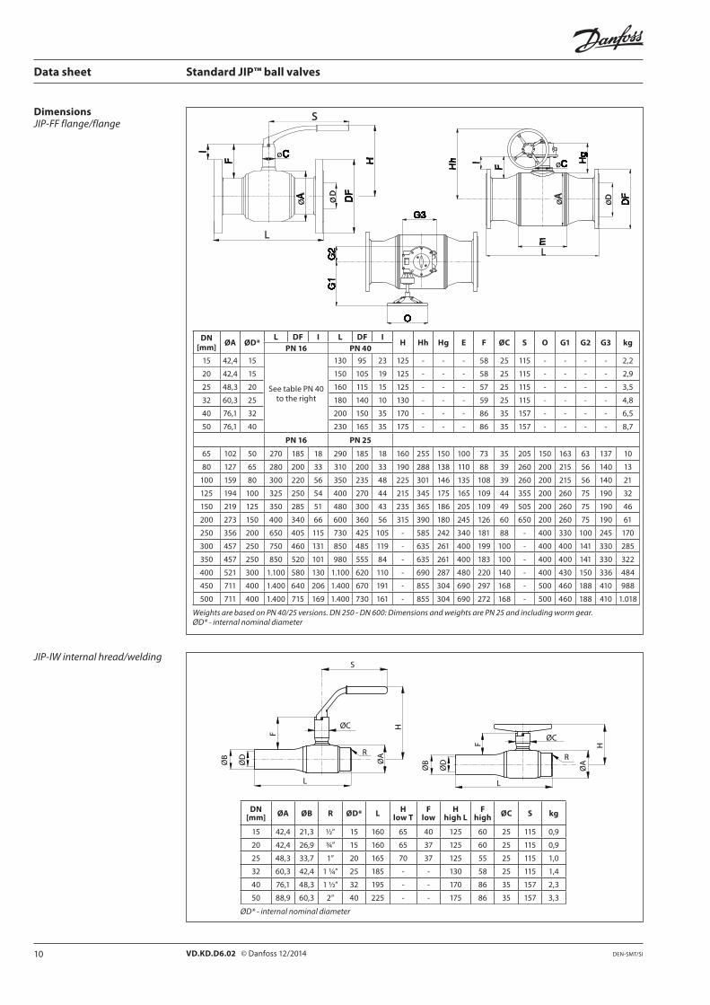
Data sheet Standard JIP™ ball valves
DimensionsJIP-FF flange/flange
JIP-IW internal hread/welding
DN[mm] ØA ØD*
L DF I L DF IH Hh Hg E F ØC S O G1 G2 G3 kg
PN 16 PN 40
15 42,4 15
See table PN 40to the right
130 95 23 125 - - - 58 25 115 - - - - 2,2
20 42,4 15 150 105 19 125 - - - 58 25 115 - - - - 2,9
25 48,3 20 160 115 15 125 - - - 57 25 115 - - - - 3,5
32 60,3 25 180 140 10 130 - - - 59 25 115 - - - - 4,8
40 76,1 32 200 150 35 170 - - - 86 35 157 - - - - 6,5
50 76,1 40 230 165 35 175 - - - 86 35 157 - - - - 8,7
PN 16 PN 25
65 102 50 270 185 18 290 185 18 160 255 150 100 73 35 205 150 163 63 137 10
80 127 65 280 200 33 310 200 33 190 288 138 110 88 39 260 200 215 56 140 13
100 159 80 300 220 56 350 235 48 225 301 146 135 108 39 260 200 215 56 140 21
125 194 100 325 250 54 400 270 44 215 345 175 165 109 44 355 200 260 75 190 32
150 219 125 350 285 51 480 300 43 235 365 186 205 109 49 505 200 260 75 190 46
200 273 150 400 340 66 600 360 56 315 390 180 245 126 60 650 200 260 75 190 61
250 356 200 650 405 115 730 425 105 - 585 242 340 181 88 - 400 330 100 245 170
300 457 250 750 460 131 850 485 119 - 635 261 400 199 100 - 400 400 141 330 285
350 457 250 850 520 101 980 555 84 - 635 261 400 183 100 - 400 400 141 330 322
400 521 300 1.100 580 130 1.100 620 110 - 690 287 480 220 140 - 400 430 150 336 484
450 711 400 1.400 640 206 1.400 670 191 - 855 304 690 297 168 - 500 460 188 410 988
500 711 400 1.400 715 169 1.400 730 161 - 855 304 690 272 168 - 500 460 188 410 1.018
Weights are based on PN 40/25 versions. DN 250 - DN 600: Dimensions and weights are PN 25 and including worm gear. ØD* - internal nominal diameter
DN [mm] ØA ØB R ØD* L H
low TF
lowH
high LF
high ØC S kg
15 42,4 21,3 ½” 15 160 65 40 125 60 25 115 0,9
20 42,4 26,9 ¾” 15 160 65 37 125 60 25 115 0,9
25 48,3 33,7 1” 20 165 70 37 125 55 25 115 1,0
32 60,3 42,4 1 ¼” 25 185 - - 130 58 25 115 1,4
40 76,1 48,3 1 ½” 32 195 - - 170 86 35 157 2,3
50 88,9 60,3 2” 40 225 - - 175 86 35 157 3,3
ØD* - internal nominal diameter
Page 11
11VD.KD.D6.02 © Danfoss 12/2014DEN-SMT/SI
S
ØC
L
F H
ØA
DF
ØB
ØD
I
ØK
ØR
ØD
ØK
q
n
p
ød
Lr
q
ØR
ØD
n Lr
Open position
DN 65 - DN 350 DN 400 - DN 600
Reduced bore
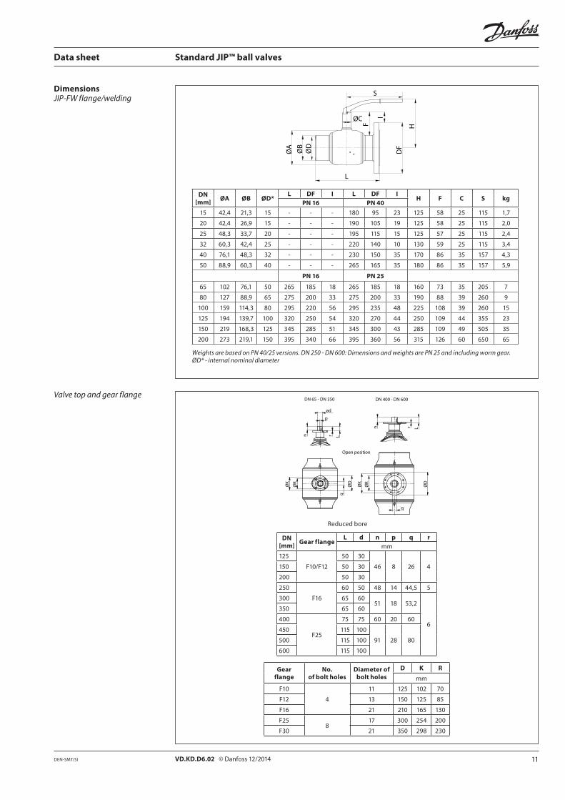
Data sheet Standard JIP™ ball valves
DN[mm] ØA ØB ØD*
L DF I L DF IH F C S kg
PN 16 PN 40
15 42,4 21,3 15 - - - 180 95 23 125 58 25 115 1,7
20 42,4 26,9 15 - - - 190 105 19 125 58 25 115 2,0
25 48,3 33,7 20 - - - 195 115 15 125 57 25 115 2,4
32 60,3 42,4 25 - - - 220 140 10 130 59 25 115 3,4
40 76,1 48,3 32 - - - 230 150 35 170 86 35 157 4,3
50 88,9 60,3 40 - - - 265 165 35 180 86 35 157 5,9
PN 16 PN 25
65 102 76,1 50 265 185 18 265 185 18 160 73 35 205 7
80 127 88,9 65 275 200 33 275 200 33 190 88 39 260 9
100 159 114,3 80 295 220 56 295 235 48 225 108 39 260 15
125 194 139,7 100 320 250 54 320 270 44 250 109 44 355 23
150 219 168,3 125 345 285 51 345 300 43 285 109 49 505 35
200 273 219,1 150 395 340 66 395 360 56 315 126 60 650 65
Weights are based on PN 40/25 versions. DN 250 - DN 600: Dimensions and weights are PN 25 and including worm gear.ØD* - internal nominal diameter
DimensionsJIP-FW flange/welding
DN[mm] Gear flange
L d n p q rmm
125
F10/F12
50 30
46 8 26 4150 50 30
200 50 30
250
F16
60 50 48 14 44,5 5
300 65 6051 18 53,2
6
350 65 60
400
F25
75 75 60 20 60
450 115 100
91 28 80500 115 100
600 115 100
Valve top and gear flange
Gear flange
No. of bolt holes
Diameter of bolt holes
D K R
mm
F10
4
11 125 102 70
F12 13 150 125 85
F16 21 210 165 130
F258
17 300 254 200
F30 21 350 298 230
Page 12
12 VD.KD.D6.02 © Danfoss 12/2014 DEN-SMT/SI
ø
ø
øø
ø
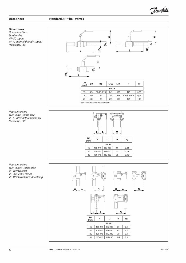
Data sheet Standard JIP™ ball valves
DimensionsHouse insertionsSingle valveJIP-CC copperJIP-IC internal thread / copperMax temp. 130°
DN [mm] ØA ØB L CC L IC H kg
PN 16
15 42,4 18/21,3/18 245 168 125 0,93
20 42,4 22 255 175 125/125/105 0,93
25 48,3 28 255 180 125 1,10
ØD* - internal nominal diameter
House insertionsTwin valve - single pipeJIP-IC internal thread/copperMax temp. 130°
DN [mm] A C H kg
PN 16
15 100-145 115-200 65 2,83
20 100-145 115-200 65 2,75
25 100-145 115-200 70 3,00
House insertionsTwin valves - single pipeJIP-WW weldingJIP -II internal threadJIP IW internal thread/welding
DN [mm] A C H kg
PN 40
15 100-145 115-200 65 2,2
20 100-145 115-200 65 2,2
25 100-145 115-200 70 2,3
32 115-160 115-200 115 3,5
Page 13
13VD.KD.D6.02 © Danfoss 12/2014DEN-SMT/SI
øø ø D
Data sheet Standard JIP™ ball valves
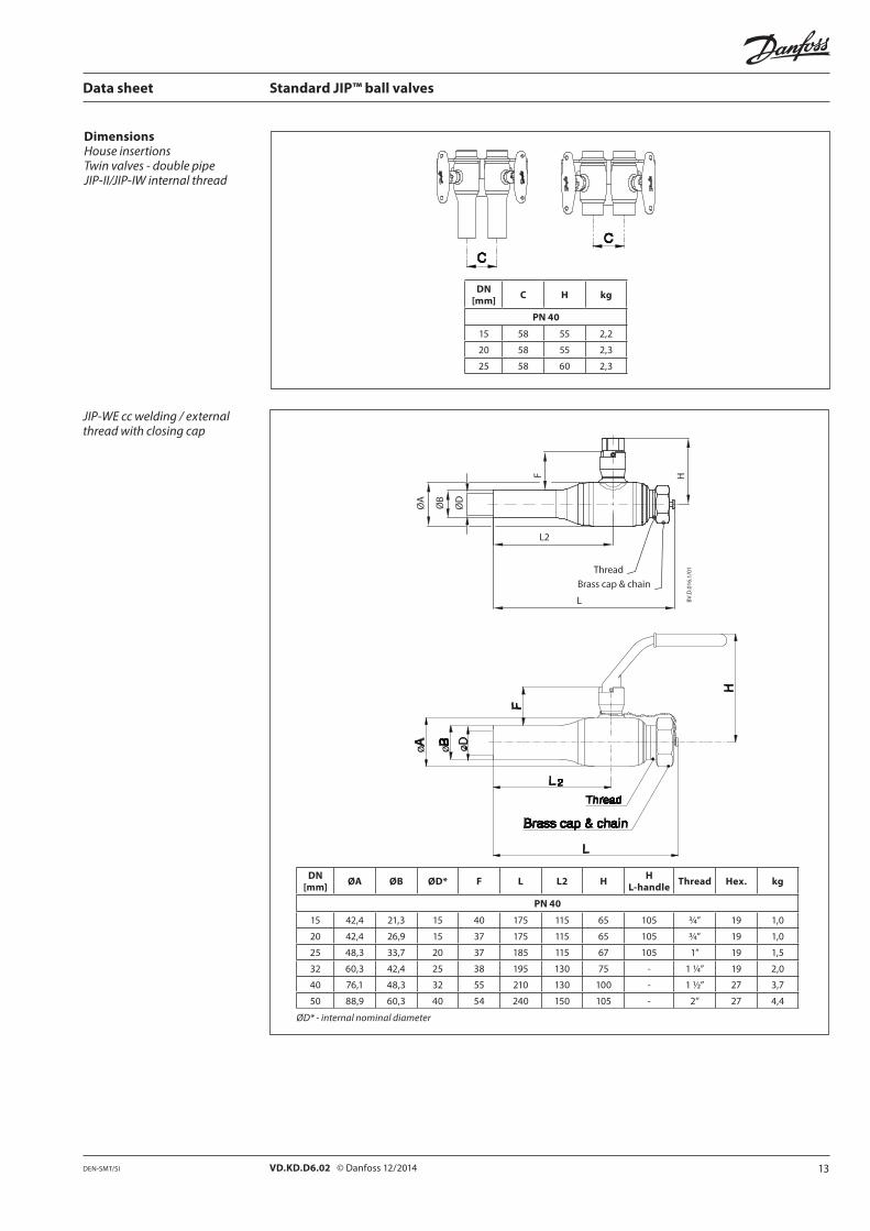
JIP-WE cc welding / external thread with closing cap
DN [mm] ØA ØB ØD* F L L2 H H
L-handle Thread Hex. kg
PN 40
15 42,4 21,3 15 40 175 115 65 105 3/4” 19 1,0
20 42,4 26,9 15 37 175 115 65 105 3/4” 19 1,0
25 48,3 33,7 20 37 185 115 67 105 1” 19 1,5
32 60,3 42,4 25 38 195 130 75 - 1 1/4” 19 2,0
40 76,1 48,3 32 55 210 130 100 - 1 1/2” 27 3,7
50 88,9 60,3 40 54 240 150 105 - 2” 27 4,4
ØD* - internal nominal diameter
DimensionsHouse insertionsTwin valves - double pipeJIP-II/JIP-IW internal thread
DN [mm] C H kg
PN 40
15 58 55 2,2
20 58 55 2,3
25 58 60 2,3
Page 14
14 VD.KD.D6.02 © Danfoss 12/2014 DEN-SMT/SI
Data sheet Standard JIP™ ball valves
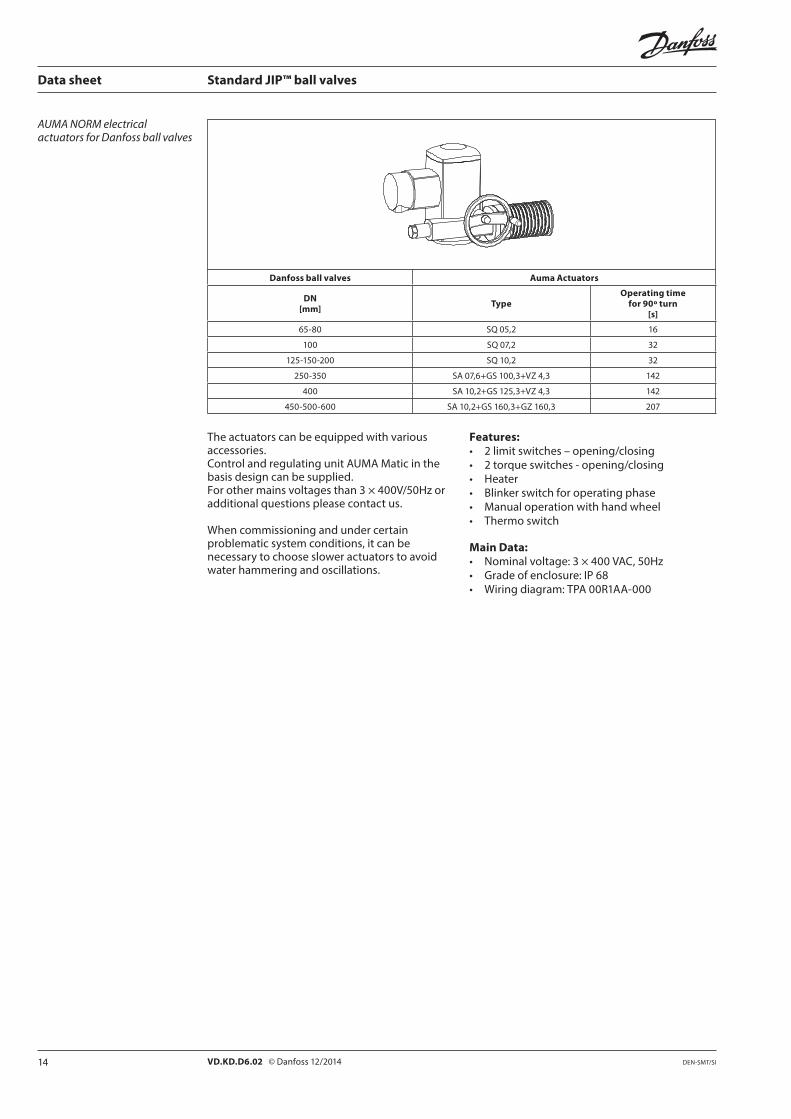
Danfoss ball valves Auma Actuators
DN[mm] Type
Operating timefor 90º turn
[s]
65-80 SQ 05,2 16
100 SQ 07,2 32
125-150-200 SQ 10,2 32
250-350 SA 07,6+GS 100,3+VZ 4,3 142
400 SA 10,2+GS 125,3+VZ 4,3 142
450-500-600 SA 10,2+GS 160,3+GZ 160,3 207
AUMA NORM electrical actuators for Danfoss ball valves
The actuators can be equipped with various accessories. Control and regulating unit AUMA Matic in the basis design can be supplied. For other mains voltages than 3 × 400V/50Hz or additional questions please contact us.
When commissioning and under certain problematic system conditions, it can be necessary to choose slower actuators to avoid water hammering and oscillations.
Features:• 2 limit switches – opening/closing• 2 torque switches - opening/closing• Heater• Blinker switch for operating phase• Manual operation with hand wheel• Thermo switch
Main Data:• Nominal voltage: 3 × 400 VAC, 50Hz• Grade of enclosure: IP 68• Wiring diagram: TPA 00R1AA-000
Page 15
15VD.KD.D6.02 © Danfoss 12/2014DEN-SMT/SI
Data sheet Standard JIP™ ball valves
Page 16
16 VD.KD.D6.02 Produced by Danfoss A/S © 12/2014
Data sheet Standard JIP™ ball valves