ALARM and using the arrow keys to change the value displayed on the screen The System 98 provides comprehensive HELP SCREENS with easy to follow step by step instructions on set-up as well OS all alarm and alert conditions. Datascope” mmHg less that the patient’s diastolic augmentation pressure. . Adjust, if needed, by pressing AUG. be&e the systolic upstroke. Attach the IAB catheter and the appropriate extender to the Safety Disk Fill the IAB Catheter and Initiate Pumping: Press the ASSIST /STANDBY key and observe “Autofilling” message Once the “Autofilling” message clears, pumping begins Ensure optimal augmentation during diastole by fine tuning IAB timing Fine tune the timing by adjusting the IAB INFLATION and DEFLATION controls if needed. 9 Verify AUG. ALARM: . Verify that the AUG . ALARM setting is approximately 10 w Adjust IAB INFLATION and IAB DEFLATION slide controls to position the inflation interval of the arterial waveform to be in at the dicrotic notch and end - NORMAL 6. Set initial Timing: 7. 8. - AUTO IAB TIMING AUTO ECG GAIN i=lll V Midpoint SLOW GAS LOSS ALARM : ON IAB V Midpoint IAB DEFLATION 1 IAB INFLATION 1: : ECG IAB FREQUENCY w Press the ZERO PRESSURE key for 2 sec. n Close the transducer Confirm Initial Pump Settings: TRIGGER SELECT IABP ON/OFF SWITCH are ON Open Helium tank and verify Helium pressure 3 4 Establish ECG and pressure connections from the patient Zero Transducer 5 n Open transducer to air orproperly licensed practitioner 1 2 Establish power, verify MAINS POWER SWITCH and until after thoroughly reading the Operating Instructions, Caution: Federal law restricts this device to sale by or on the order of a physician Dais guide is a reference for personnel trained in using the Datascope System 98. Complete instructions for operation are provided in the Datascope Operating Instructions: System 98 Manual (00 70-00-0402). Do not use this guide Intia-Aortic Balloon Pump Abbreviated Operator’s Guide INITIAL SET-UP Note: 98 System
Transcript
ALARM and using the arrow keys tochange the value displayed on the screen
The System 98 provides comprehensiveHELP SCREENS with easy to follow step by stepinstructions on set-up as well OS all alarm andalert conditions.
Datascope”
mmHg less that thepatient’s diastolic augmentation pressure.
. Adjust, if needed, by pressing AUG.
be&e the systolic upstroke.
Attach the IAB catheter and theappropriate extender to the Safety Disk
Fill the IAB Catheter and Initiate Pumping:
Press the ASSIST /STANDBY key andobserve “Autofilling” message
Once the “Autofilling” message clears,pumping begins
Ensure optimal augmentation duringdiastole by fine tuning IAB timing
Fine tune the timing by adjusting the IABINFLATION and DEFLATION controls ifneeded.
9 Verify AUG. ALARM:
. Verify that the AUG. ALARM setting isapproximately 10
w Adjust IAB INFLATION and IAB DEFLATION
slide controls to position the inflationinterval of the arterial waveform tobe in at the dicrotic notch and end
- NORMAL
6. Set initial Timing:
7.
8.
- AUTO
IAB TIMING AUTO
ECG GAIN
i=lll
V Midpoint
SLOW GAS LOSS ALARM : ON
IAB
V Midpoint
IAB DEFLATION
1IAB INFLATION
1: : ECG
IAB FREQUENCY
w Press the ZERO PRESSURE key for 2 sec.
n Close the transducer
Confirm Initial Pump Settings:
TRIGGER SELECT
IABP ON/OFF SWITCH are ON
Open Helium tank and verify Heliumpressure
3
4
Establish ECG and pressure connectionsfrom the patient
Zero Transducer
5
n Open transducer to air
orproperly licensed practitioner
1
2
Establish power, verify MAINS POWERSWITCH and
until after thoroughly reading the OperatingInstructions, Caution: Federal law restricts this device to sale by oron the order of a physician
Dais guide is a reference for personnel trained in using theDatascope System 98. Complete instructions for operation are
provided in the Datascope Operating Instructions: System 98 Manual
(00 70-00-0402).
Do not use this guide
Intia-Aortic Balloon Pump
Abbreviated Operator’s Guide INITIAL SET-UP
Note:
98System
deJation control.
using pressure trigger, the System 98 willautomatically adjust deflation timing early to avoid interfering with systolic ejection.Do not attempt to adjust the
rfa dysrhythmia develops while
AUXILIARY ARROW keys. The pressure triggerthreshold is displayed with the trigger source on the monitor screen and the arterialwaveform is marked to indicate the trigger point. When using pressure trigger, theballoon must be fully deflated before the upstroke of systole.Precaution: Pressure triggering is NOT recommended for use with irregular rhythms.
mmHg can be selected using the 7-30 Optionally, a fixed pressure trigger threshold
from
98 will automatically adapt the pressure trigger threshold to systolic pulseheight of the arterial pressure waveform.
the preferred trigger mode
PRESSURE:
The systolic upstroke of the arterial waveform is the trigger event. In normal operation,the System
(xxx being the amount of gain from 0.15 to 3.00) will be displayed inplace of ECG SIZE on the monitor screen when variable ECG gain is used.Note: ECG is
xxx
When the ECG trigger mode is selected, the ECG gain can be varied using theAUXILIARY ARROW keys.
The ECG gain can be varied from 0.15 to 3.00, relative to a normal gain of 1.0.
VAR x
this mode.98
screen. ESIS (electrosurgical interference suppression) is automatic in
98 uses to identify the beginning of the cardiaccycle. There are five different trigger selections available.
ECG:
The R wave of the ECG is the trigger event.
Pacer rejection is automatic provided the pacer spikes are enhanced on the System
TRIGGER SELECT
Trigger is the signal the System
the presence of a ventricularpaced rhythm.
I
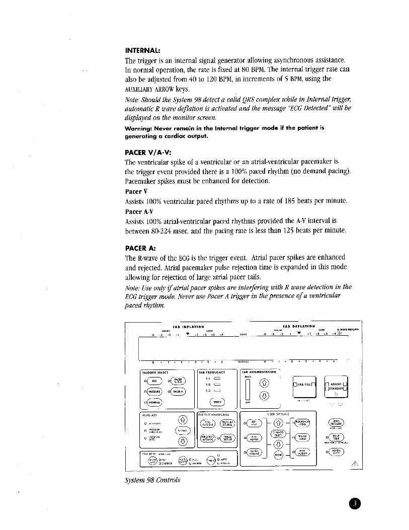
System 98 Controls
V/A-V:
The ventricular spike of a ventricular or an atrial-ventricular pacemaker isthe trigger event provided there is a 100% paced rhythm (no demand pacing).Pacemaker spikes must be enhanced for detection.Pacer VAssists 100% ventricular paced rhythms up to a rate of 185 beats per minute.Pacer A-VAssists 100% atrial-ventricular paced rhythms provided the A-V interval isbetween 80-224 msec. and the pacing rate is less than 125 beats per minute.
PACER A:
The R-wave of the ECG is the trigger event. Atria1 pacer spikes are enhancedand rejected. Atria1 pacemaker pulse rejection time is expanded in this modeallowing for rejection of large atria1 pacer tails.Note: Use only ifatrialpacer spikes are interfering with R wave detection in theECG trigger mode. Never use Pacer A trigger in
“Ecc Detected” will bedisplayed on the monitor screen.Warning: Never remain in the Internal trigger mode if the patient isgenerating a cardiac output.
PACER
BPM, using theAUXILIARY ARROW keys.Note: Should the System 98 detect a valid QRS complex while in Internal trigger,automatic R wave deflation is activated and the message
INTERNAL:
The trigger is an internal signal generator allowing asynchronous assistance.In normal operation, the rate is fixed at 80 BPM. The internal trigger rate canalso be adjusted from 40 to 120 BPM, in increments of 5
1:2 is illustrated below:
In both AUTO and MANUAL timing, it is possible to view the inflation period whileassisting, by pressing and holding the INFLATION INTERVAL key. The highlightedportion indicates the period of balloon inflation. Vertical Inflation Markers locatedbelow the arterial waveform will also be displayed when the INFLATION INTERVALkey is pressed.
98 will adjust timingautomatically to accommodate changes in the patient’s heart rate and rhythm.
MANUAL TIMING
In manual timing, the operator sets fixed inflation and deflation points as a functionof time relative to the trigger point. If the heart rate varies by more than 10 BPM,readjustment of timing may be required.Timing at a frequency of
TIMING
Timing refers to the positioning of inflation and deflation points on the arterialwaveform. Inflation should occur at the onset of diastole and deflation should occurprior to ventricular ejection. On the monitor screen, with the pump in Standby, theInflation Marker on the arterial waveform identifies the selected period of ballooninflation. Vertical timing marks, located below the arterial waveform, are alsoavailable to aid with initial timing.
,Dicrotic Notch
Inflation Marker
AUTO TIMING
With initial set-up, the operator selects the desired inflation and deflation pointswhile in Standby, utilizing the Inflation Marker on the arterial waveform or thevertical Inflation Markers located below the arterial waveform. After initiatingassist, the IAB INFLATION and IAB DEFLATION controls can be adjusted to maximizeaugmentation and hemodynamic unloading. The System
- Pressure Trigger is selected but the transducer hasZero Transducer not been zeroed
Trigger Interference Electrosurgical interference while in Pacer Trigger
Check Pacer Timing V/A-V Pacer Trigger requirements have not beenmet
OPERATOR INTERVENTION
Assess the selected trigger and associated trigger criteria. If necessary, changetrigger selection and resume pumping by pressing the ASSIST/STANDBY key.
,,.....,.,No Pressure Trigger Valid trigger does not exist while in Pressure
Trigger
No Pressure Trigger
IABP assist is suspended and a steady tone will sound.
TRIGGER ALARMS
These alarms indicate the selected trigger source is either not available ornot reliable. Pumping is suspended and a steady tone sounds. Pumping willautomatically resume once the trigger has been reestablished.
MESSAGE CAUSE
No Trigger Valid trigger does not exist
98 Operating Instructions.
ALARMSALARM messages are displayed in the ALARM MESSAGES section of the monitordisplay.
98 provides the operator with comprehensive HELP SCREENS forall of the Alarms and Alerts. In the presence of an Alarm or Alert message,the operator can utilize the HELP SCREEN by pressing the HELP key on thecontrol panel. The operator will be provided with step by step troubleshootinginstructions. Detailed information on all Alarms, Alerts, and Status/Prompts isprovided in the System
SYSTEM ALARMS, ALERTS, AND STATUS/PROMPTS
The System
IAB gas loss andcatheter alarms are disabled. The message, “Gas Loss And Catheter AlarmsDisabled” will be displayed in the Advisory section of the display. The IAB status
bar will not be active.
Warning: Under certain heart rate and timing conditions, catheter alarms may besuspended. Refer to the Operating Instructions for further detail.
IAB procedure, stop pumping and notify the physicianimmediately.
Warning: When the System is operated in MANUAL FILL, the
FILL key. Resume pumping by pressingASSIST/STANDBY.Warning: If blood is observed within the catheter or catheter extender tubing atany time during the
“AutofillFailure-No Helium” open or replace Helium tank if necessary. Inspect the IABcatheter and catheter extender for evidence of a kink or restriction to Helium flow.Fill the IAB, if instructed, by pressing the IAB
autofill tubing and drain port. Verify all connections are leak free. For
.
OPERATOR INTERVENTION
Inspect the IAB and catheter extender tubing for any evidence of a leak, includingthe safety disk/condensate removal assembly connections, IAB catheter connections,
Autofill Required The System 98 has been switched from manual fillto auto fill or pump was placed in standbyduring the two hour scheduled auto fill
.
Autofill Failure IAB could not be automatically filled but Heliumsupply is adequate
.
- IAB could not be adequately filled due to anNo Helium inadequate supply of HeliumAutofill Failure
IAB catheter or catheter extender tubing kinked orballoon not fully unwrapped
Blood Detected Blood has migrated into the drain tubing due to a leakin the IAB.
LAB Catheter
IAB catheter or catheter extension tubing disconnected
Check
IAB Disconnected
IAB catheter or catheter extender
JABcatheter circuit
Rapid Gas Loss Large leak in
98 continually monitors specific parameters within the closed patientpneumatic system. If a change is detected or a specific parameter is violated, IABPassist is suspended and a continuous tone will sound.
MESSAGE CAUSE
Leak in IAB Circuit Small gas loss, gas gain, or slow leak in the
CATHETER ALARMS
The System
#
System Failure Microprocessor or other electronic/pneumaticfailure
Safety Disk Test Fails Leak in safety disk/condensate removal assemblyor pneumatic fitting during a safety disk leak test
OPERATOR INTERVENTION
Refer to help screens and/or the Operating Instructions.
1:2. Pumping suspendeddue to a Low Vacuum alarm will resume automatically when vacuum is restored.If either alarm condition persists, contact Datascope service.
SYSTEM SURVEILLANCE ALARMS
The System 98 provides internal surveillance of certain parameters within theconsole.
MESSAGE CAUSE
Electrical Test Fails Electrical failure during power-up diagnosticsCode
Low Vacuum Insufficient or no compressor vacuum
OPERATOR INTERVENTION
Press the ASSIST/STANDBY key to resume pumping. If “Low Vacuum” persists andthe patient is tachycardiac, change IAB FREQUENCY to
.I.....
.......................
High Drive Pressure Regulated drive pressure exceeds acceptablelevel
(EXT) External battery time is below 30 minutes ofoperating time
ECG Detected ECG activity exists while in Internal Trigger
........
Low Battery ........ ..........I .... .................. .............................................................,..,..Low Battery Battery time is below 30 minutes of operating time
.24-811 reserve
-40 BPM
Low Helium Helium supply is below
.
Heart Rate Low Heart rate
........ CAUSE
Augmentation Below Diastolic augmentation has dropped below limit setLimit Set
Irregular Trigger Pressure trigger in the presence of irregular rhythmsor with deflation set too late
LtzB pumping isnot suspended with Alert conditions. A double beep tone signals the operator thatcorrective action is required. Alert conditions that do not require immediateintervention will result in a double beep tone that repeats for 30 seconds(no tone will sound for “Heart Rate Low”). The Alert message remains displayeduntil the alert condition is corrected.
MESSAGE
ALERTSAlert messages are displayed in the ADVISORY section of the screen.
Status/Prompt messages are displayed in the ADVISORY section of the display.Status/Prompt messages do not sound any tones (with the exception of “UnplugDisk Outlet”
1:3, the unassisted systolic and diastolicpressures will be displayed on the monitor immediately below the assistedsystolic and diastolic pressures.
1:2 or
IAB should not remain immobile for more than 30 minutes in situ.
ARTERIAL PRESSURE DISPLAY
When IAB Frequency is
i%e
98 is completely isolated from thepatient, however, the operator should stand clear of the System during defibrilla-tion. This is especially important during battery (ungrounded) operation.
Note:
98 automatically deflates when an ectopic beat is sensed and willthen inflate the IAB during diastole of the ectopic. To ensure reliable triggeringwith ectopics, select the lead that minimizes the amplitude differences betweenthe normal QRS and the ectopic. If the arterial pressure decreases during theectopic beat, the diastolic augmentation pressure may also decrease.
l Cardiac Arrest/DefibrillationIf possible, use ECG or PRESSURE Trigger during CPR. The system will synchro-nize trigger to the rate and rhythm of chest compressions. If ECG or PRESSURETrigger cannot be utilized, INTERNAL Trigger may be utilized to allow balloonmovement. When defibrillating, the System
IAB INFLATION and IAB DEFLATION should be adjusted to position the InflationMarkers of the arterial waveform to correspond with diastole. Moving the IABDEFLATION slide control to the extreme right will result in automatic R wavedeflation. The Status message “R-Wave Deflate” will be displayed in the ADVISORYsection of the monitor. Adjust the augmentation alarm limit using the AUGALARM key and the UP and DOWN ARROW keys to accommodate any change inthe patient’s pressure.
l EctopicsThe System
- Use AUTO TIMING and ECG TRIGGER.
LEAD/EXT. key, and the bedside monitor is in the diagnosticoutput mode.
There are several methods to correct conditions which alter or hamper theacquisition of a reliable ECG. Repositioning electrodes to the anterior thoracicchest or replacement of the ECG electrodes, checking that the patient cable isproperly connected, choosing an alternate lead selection and adjusting the ECG Gainsetting are the most common solutions. If the ECG signal is acquired from a bedsidemonitor, ensure the appropriate cable is utilized, ECG External is selected using thePATIENT WAVEFORM ECG
IABP.l They can now connect with the IABP to view waveforms, patient data, and
pump information.
98 is equipped with a telephone jack located on the rear panelbelow the Helium tank. When a direct dial analog telephone line is connectedfrom the telephone jack in the wall to the telephone jack in the IABP, patientdata, waveforms, and pump information can be accessed from a remote locationusing a computer and the PC-IABP software.To use the modem capabilities of the System 98:l Connect a telephone cord from the telephone jack in the wall to the port
labeled “Phone Line” on the rear panel of the System 98 below the Heliumtank.
l From a separate telephone line, contact the person who is going to connectby computer with the IABP and provide them with the phone number of thetelephone line connected to the
98 will proceed with the test which takes approximately 6 minutes.When the test is complete, a 10 second tone will sound and the message“System Test O.K.” or “Safety Disk Test Fails” is displayed adjacent to theADVISORY section.If the Safety Disk leak test fails, check all pneumatic connections. Turn thepump OFF and repeat from Step 1. If the Safety Disk Leak Test fails again,replace the Safety Disk.
Warning: This procedure must not be performed when the system is connectedto the patient.
PC-IABP REMOTE MODEM DIAGNOSTICS
The System
luer lock plug or a closedstopcock.
4. The System
IAB CATHETER EX TENDER INPU T with a
CHANGE IN PRESSURE MONITORING SITE
If the arterial pressure monitoring site is changed while pumping, quickly pressand release the INFLATION INTERVAL key to recalculate arterial pressuretransmission delay. This will ensure accurate digital pressure displays andappropriate display of the Inflation Markers.
SAFETY DISK LEAK TEST
The Safety Disk should be removed from the condensate removal module andreplaced after 1000 hours of use or 2 years, whichever comes first. The SafetyDisk should also be checked on a regular basis. To initiate the Safety Disk LeakTest, the following procedure should be performed:1. Press and hold the IAB FILL key while turning on the power. Release the IAB
FILL key when the message “Leak Testing Safety Disk” is displayed in theADVISORY section of the monitor screen.
2. After approximately 10 seconds, a tone will sound and the message “PlugDisk Outlet” will be displayed adjacent to the ADVISORY section.
3. Plug the
IAB and resume pumping.
9V alkalinebattery. Slide the cover back into position.
TRANSPORT CONSIDERATIONSIf it is necessary to disconnect patient connections or to detach the battery from theconsole to facilitate movement into a transport vehicle or aircraft, the System 98will hold pump settings in memory for 15 minutes. Once the patient and pump arereattached, turn the power ON, verify timing settings, press ASSIST/STANDBY to AutoFill the
6LF22, or equivalent 6LR61, ,If battery replacement is necessary, remove the cover of the battery compartment,and lift out the old battery. Install a new
98 is equipped with a doppler located in the upper storage compartmenton the side of the System 98 cart.To Use:1. After removing the doppler from the storage compartment, press the on/off key
located on the front of the doppler, The LCD will display the power ON indicator.
2. Place a small amount of coupling gel on the doppler probe or at the site to beexamined.
3. Place the probe at a 45 degree angle over the artery to be assessed.
4. Listen for pulsatile blood flow sounds, adjust volume control as needed.
STRIP key. To end the recording, press the PRINT STRIP key again.
Trend data can also be printed from the recorder using the Printer Menu.
A Printer Menu allows the user to configure the printer for specific functions.Press the PRINTER MENU key to access the printer configuration menu. Use the UP andDOWN ARROW keys to highlight a menu item and press the SELECT/CHANGE key toselect specific options for the function. When finished, press DONE to save changes.
PREFERENCES MENU
The preferences menu allows the operator to adjust Audio Preferences, DisplayPreferences, or to Set Time and Date.
Press the P REFERENCES MENU key to access the preferences menu. Use the UP andDOWN ARROW keys to highlight a menu item. Press the SELECT/CHANGE key to selecta menu item or to change a preference item. Press DONE to exit the PreferencesMenu and save changes.
DOPPLER
The System
PRINT
STRIP CHART RECORDER
The dual trace recorder provides a hard copy record of ECG and arterial pressure, ECG
and balloon pressure waveform, or arterial pressure and balloon pressure waveform.Alarm/ Advisory messages, Timing and Trigger mode, heart rate and arterial pressuresare provided at the end of the strip. Trigger event markers are annotated across the topof the strip with an inflation marker at the bottom of the strip. To activate the recorder,press the
mmHg respectively. These pressure changesoccur approximately every 1,000 feet of rise or 2,000 feet of drop in altitude.The Auto Fill mode should be used during air transport. If the Auto Fill modecannot be used and the Manual Fill mode is required, a Manual Fill must beperformed at the same intervals that an Auto Fill would occur.
IAB when local atmospheric pressuredecreases or increases by 25 or 50
98 is operated from theexternal DC power source. Interruption of the external DC source will result inportable internal battery operation. Refer to the Operating Instructions foradditional detail.
ALTITUDE CHANGES DURING AIR TRANSPORT
For proper operation during air transport, the System 98 balloon pressuremust adapt to local atmospheric pressure. In the Auto Fill mode, the systemwill automatically purge and fill the
98 can also be powered from a voltage compatible external 24 voltDC power source. The message, “Battery in Use (EXT)” will be displayed in theADVISORY section of the monitor when the System
98 can be supplied from an emergency vehicle inverter.The inverter should be checked for proper operation. Refer to the OperatingInstructions for vehicle inverter specifications. Interruption of the vehicle inverterAC power will result in portable internal battery operation.
Portable Operation-External DC Source:The System
BAITERY CHARGING LED is either continuously illuminated or is flashingwhen the system is plugged in.
If the unit is stored for an extended period and AC power is unavailable,disconnect the system battery pack from the console. Refer to the OperatingInstructions for additional detail.
Portable Operation from Vehicle Inverter:AC power for the System
98 switches automatically to portable operation. Thebatteries recharge whenever the System 98 is plugged into an AC outlet with theMAINS switch ON. To maintain batteries at full charge and maximize battery life, itis recommended that the System be plugged in at all times even when not in use.
The message, “Battery In Use,” will be displayed in the ADVISORY section of themonitor and the BATTERY INDICATOR will be display on the monitor screen when-ever the System is operated from the internal batteries. When approximately 30minutes of battery operation time remains, the following occurs: The message,“Low Battery,” is continuously displayed in the ADVISORY section and a doublebeep alarm is activated for 30 seconds.
To return to AC power, plug the AC power cord into an AC outlet. The Systemautomatically switches to AC operation and the internal batteries will recharge.Verify
PORTABLE OPERATION
Portable Operation from Internal Batteries:To switch from AC power to battery operation, unplug the power cord fromthe AC outlet. The System
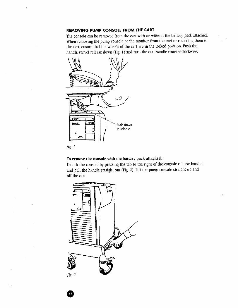
fig. 1
To remove the console with the battery pack attached:Unlock the console by pressing the tab to the right of the console release handleand pull the handle straight out (Fig. 2). Lift the pump console straight up andoff the cart.
REMOVING PUMP CONSOLE FROM THE CART
The console can be removed from the cart with or without the battery pack attached.When removing the pump console or the monitor from the cart or returning them tothe cart, ensure that the wheels of the cart are in the locked position. Push thehandle swivel release down (Fig. 1) and turn the cart handle counter-clockwise.
,JRelease Levers
-
To remove the console by detaching the battery pack:With the console on the cart, lift the battery release levers to the unlockposition (Fig. 3). Lift the console straight up and off the cart. To release thebattery from the cart, unlock the battery pack by pressing the tab to the rightof the console release handle and pull the release handle straight out. Lift thebattery pack off the cart. With the release levers in the unlocked position, liftthe pump console and lower it straight down onto the battery pack. Return therelease levers to the locked position (Fig 4).
Pump
1.973.244.6100 (outside the U.S.)
Datascope”
1.800.777.4222 (within the U.S.)
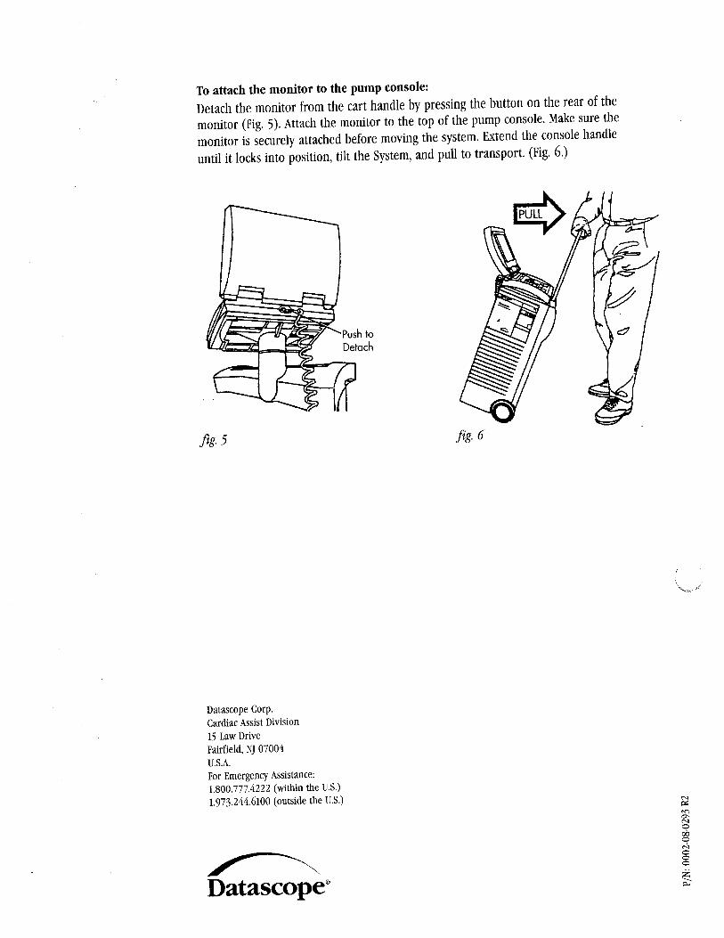
To attach the monitor to the pump console:Detach the monitor from the cart handle by pressing the button on the rear of themonitor (Fig. 5). Attach the monitor to the top of the pump console. Make sure themonitor is securely attached before moving the system. Extend the console handleuntil it locks into position, tilt the System, and pull to transport. (Fig. 6.)
Datascope Corp.Cardiac Assist Division15 Law DriveFairfield, NJ 07004U.S.A.For Emergency Assistance:


![[XLS] · Web view118 118 45 45 88 118 118 128 128 128 128 98 98 12 12 12 98 98 98 88 98 58 128 128 98 98 98 98 98 98 98 98 12 12 98 98 98 98 12 98 98 98 58 12 98 98 98 98 98 98 98](https://static.documents.pub/doc/80x56/5b1aab787f8b9a1e258df5af/xls-web-view118-118-45-45-88-118-118-128-128-128-128-98-98-12-12-12-98-98.jpg)


