96
Cleco ® DC Electric Assembly Tools SP-1020-EN 0909 7.5M

Cleco ®
DC Electric Assembly Tools
SP-1020-EN 0909 7.5MSPEcificatioNS SubjEct to chaNgE without NoticE. coPYRight © 2009 cooPER iNDuStRiES. PRiNtED iN uSa.
Cooper Tools1000 Lufkin Roadapex, Nc 27539Phone: 919-387-0099fax: 919-387-2614www.coopertools.com
Sales & Service Centers Note: all locations may not service all products. Please contact the nearest Sales & Service center for the appropriate facility to handle your service requirements.
SP
-102
0-E
N 0
909
7.5M
CLE
CO
DC
ELE
CTR
IC A
SS
EM
BLY
TOO
LSSP-1020-EN 0909 7.5M
Dallas, TXCooper ToolsSales & Service Center1470 Post & Paddockgrand Prairie, tX 75050tel: 972-641-9563fax: 972-641-9674
Detroit, MICooper ToolsSales & Service Center2630 Superior courtauburn hills, Mi 48326tel: 248-391-3700fax: 248-391-7824
Houston, TXCooper ToolsSales & Service Center6550 west Sam houston Parkway North, Suite 200houston, tX 77041tel: 713-849-2364fax: 713-849-2047
Lexington, SCCooper Tools670 industrial DriveLexington, Sc 29072tel: 800-845-5629tel: 803-359-1200fax: 803-358-7681
Los Angeles, CACooper ToolsSales & Service Center15503 blackburn ave Norwalk, ca 90650tel: 562-926-0810fax: 562-802-1718
Seattle, WACooper ToolsSales & Service Center2865 152nd ave N.E. Redmond, wa 98052tel: 425-497-0476fax: 425-497-0496
York, PACooper ToolsSales & Service Center3990 East Market StreetYork, Pa 17402tel: 717-755-2933fax: 717-757-5063
CanadaCooper ToolsSales & Service Center5925 McLaughlin RoadMississauga, ont. L5R 1b8 canadatel: 905-501-4785fax: 905-501-4786
Westhausen, EMEACooper Power ToolsGmbH & Co. OHGPostfach 30D-73461 westhausengermanyPhone: +49 (0) 73 63/ 81-0fax: +49 (0) 73 63/ [email protected]
Coventry, UKCooper Power ToolsGmbH & Co. OHGunit g Quinn closeSeven Stars industrial Estatewhitletcoventry cV3 4LhuKPhone: +44-2476-3089 60fax: +44-2476-3089 69
Cooper ToolsP.o. box 1410Lexington, Sc 29071-1410uSaPhone: 800-845-5629 803-359-1200fax: 803-359-0822
Cooper Tools2630 Superior courtauburn hills, Mi 48326Phone: 248-391-3700 888-332-6061fax: 248-391-7824
Cooper Tools5925 McLaughlin RoadMississauga, ontariocanada L5R 1b8Phone: 905-501-4785fax: 905-501-4786
Cooper Tools de México S.A. de C.V.Libramiento La joya No. 1 bodega No. 2Esq. Politécnico barrio San josécuautitlán, Edo de México c.P. 54870Phone: +52-55-5899-9510fax: +52-55-5870-5012
Cooper Tools Industrial Ltda.av. Liberdade, 4055Zona industrial - iporanga18087-170 Sorocaba, SP braziltel: +55-15-3238-3929fax: +55-15-228-3260
Cooper Power Tools SASZone industrielle – b.P. 2877831 ozoir-la-ferrière cedexfrancetéléphone: +33-1-6443-2200téléfax: +33-1-6440-1717
Cooper Power ToolsGmbH & Co. OHGPostfach 30D-73461 westhausengermanyPhone: +49 (0) 73 63/ 81-0fax: +49 (0) 73 63/ [email protected]
Cooper (China) Co., Ltd.955 Sheng Li Road,heqing Pudong, Shanghaichina 201201tel: +86-21-28994176 +86-21-28994177fax: + 86-21-51118446
www.coopertools.com
ww
w.coopertools.com

Cooper Tools provides a complete resource for power tools on-line. Our website www.coopertools.com offers product information, service literature, brand catalogs, press releases and more. A dominant source of information, the Cooper Tools website is your source for application solutions on-line.
Making your job easier is our goal!You can access service literature anytime. Choose a category such as Assembly Tools or Material Removal Tools from the main menu and then click on the brand you’re looking for. You’ll be on your way to any current service literature you need, whether it’s Cleco, Apex, Master Power, or any of our power tool brands.
Up-to-date product catalogs are also avail-able online providing
you with current information on our broad product line. Even Material Safety Data Sheets (M.S.D.S.) for Safety and Disposal Information are available on our website.
It’s simple!Our Customer Care section provides you with information such as answers to frequently asked questions or contact phone numbers and addresses for your area of the country. You can browse through the What’s New information to learn how Cooper Tools continues to be your source for solutions.
For even faster searches, you can go direct to a brand site by simply entering the brand name. Entering www.dotco-tools.com takes you directly to the Dotco brand site.
What is the future of www.coopertools.com? A dynamic site continuing to focus on your need for up-to-date information on the latest Cooper Tools’ offerings that you can access anytime you need...twenty-four hours a day, seven days a week!
Cooper Tools Is On The Web!
Cooper Tools Division has attained ISO 9001 Quality System Certification for seven of our facilities. The driving force behind the implementation of the Quality System is the commitment “to provide our customers with the best value delivered by offering only products and services that meet or exceed their expectations”.
Lexington, South Carolina
Springfield, OhioDayton, Ohio Hicksville, Ohio
Braunschweig, Germany Westhausen, Germany Ozoir-la-Ferrière, France
ISO 9001 www.coopertools.com
1
Table of Contents
Warranty, Lubrication, Safety . . . . . . . . . . . . . . . . . . . . . . . . . . . . . 2
DC Tool Cross Reference . . . . . . . . . . . . . . . . . . . . . . . . . . . . . . . . 3
Model Number Index . . . . . . . . . . . . . . . . . . . . . . . . . . . . . . . . . . . 4
DC Electric Tools Introduction . . . . . . . . . . . . . . . . . . . . . . . . . . . . 6
Cordless Transducer Control Tools . . . . . . . . . 10 Right Angle Tools . . . . . . . . . . . . . . . . . . . . . . . . . . . . . . . . . . . 14 Pistol Tools . . . . . . . . . . . . . . . . . . . . . . . . . . . . . . . . . . . . . . . . 15 Tube Nut Tools . . . . . . . . . . . . . . . . . . . . . . . . . . . . . . . . . . . . . 16 Crowfoot Tools . . . . . . . . . . . . . . . . . . . . . . . . . . . . . . . . . . . . . 17 TMEC Controllers . . . . . . . . . . . . . . . . . . . . . . . . . . . . . . . . . . . 18 LiveWire Power Module . . . . . . . . . . . . . . . . . . . . . . . . . . . . . . 18 Cordless Tool Accessories . . . . . . . . . . . . . . . . . . . . . . . . . . . . 19
Corded Transducer Control Tools . . . . . . . . . . . 20 Right Angle Tools . . . . . . . . . . . . . . . . . . . . . . . . . . . . . . . . . . . . 22 Inline Tools . . . . . . . . . . . . . . . . . . . . . . . . . . . . . . . . . . . . . . . . . 24 Pistol Tools . . . . . . . . . . . . . . . . . . . . . . . . . . . . . . . . . . . . . . . . . 26 Push-to-Start Tools . . . . . . . . . . . . . . . . . . . . . . . . . . . . . . . . . . 27 Inline Floating Spindle Tools . . . . . . . . . . . . . . . . . . . . . . . . . . . 28 Hold & Drive Tools . . . . . . . . . . . . . . . . . . . . . . . . . . . . . . . . . . . 30 Flush Socket Tools. . . . . . . . . . . . . . . . . . . . . . . . . . . . . . . . . . . 31 Tube Nut Tools . . . . . . . . . . . . . . . . . . . . . . . . . . . . . . . . . . . . . . 32 Crowfoot Tools . . . . . . . . . . . . . . . . . . . . . . . . . . . . . . . . . . . . . . 33 Right Angle Floating Spindle Tools . . . . . . . . . . . . . . . . . . . . . . 34 TME & TMEM “Mini” Controllers . . . . . . . . . . . . . . . . . . . . . . . 36 Transducer Control Tool Accessories . . . . . . . . . . . . . . . . . . . 39
Corded Current Control Tools . . . . . . . . . . . . . . 42 Right Angle Tools . . . . . . . . . . . . . . . . . . . . . . . . . . . . . . . . . . . . 44 Inline Tools . . . . . . . . . . . . . . . . . . . . . . . . . . . . . . . . . . . . . . . . . 45 Pistol Tools . . . . . . . . . . . . . . . . . . . . . . . . . . . . . . . . . . . . . . . . 46 Push-to-Start Tools . . . . . . . . . . . . . . . . . . . . . . . . . . . . . . . . . . 47 Inline Floating Spindle Tools . . . . . . . . . . . . . . . . . . . . . . . . . . . 48 Hold & Drive Tools . . . . . . . . . . . . . . . . . . . . . . . . . . . . . . . . . . . 49 Flush Socket Tools . . . . . . . . . . . . . . . . . . . . . . . . . . . . . . . . . . 50 Tube Nut Tools . . . . . . . . . . . . . . . . . . . . . . . . . . . . . . . . . . . . . 51 Crowfoot Tools . . . . . . . . . . . . . . . . . . . . . . . . . . . . . . . . . . . . . 52 Right Angle Floating Spindle Tools . . . . . . . . . . . . . . . . . . . . . 54 TMEI Controllers . . . . . . . . . . . . . . . . . . . . . . . . . . . . . . . . . . . . 56 Current Control Tool Accessories . . . . . . . . . . . . . . . . . . . . . . 57
Balance Arms . . . . . . . . . . . . . . . . . . . . . . . . . . . . . . . . . . . . . . 58
Tightening Manager Software . . . . . . . . . . . . 60 TM-COM . . . . . . . . . . . . . . . . . . . . . . . . . . . . . . . . . . . . . . . . . . 60 TM-COM1 . . . . . . . . . . . . . . . . . . . . . . . . . . . . . . . . . . . . . . . . . 61
TM-COM1M . . . . . . . . . . . . . . . . . . . . . . . . . . . . . . . . . . . . . . . 62
Automated Systems . . . . . . . . . . . . . . . . . . . . 64 Introduction . . . . . . . . . . . . . . . . . . . . . . . . . . . . . . . . . . . . . . . . 64 Articulating Arms & Cable Management . . . . . . . . . . . . . . . . . 66 Torque Handling System . . . . . . . . . . . . . . . . . . . . . . . . . . . . . . 67 Wheelnut Fastening . . . . . . . . . . . . . . . . . . . . . . . . . . . . . . . . . . 68 Fixtured Spindles . . . . . . . . . . . . . . . . . . . . . . . . . . . . . . . . . . . . 71 Fixtured Spindle Accessories . . . . . . . . . . . . . . . . . . . . . . . . . . 75 Controllers & Accessories . . . . . . . . . . . . . . . . . . . . . . . . . . . . . 76 Mobile Assembly Station (MAS) . . . . . . . . . . . . . . . . . . . . . . . . 80
General Accessories . . . . . . . . . . . . . . . . . . . . 84
Quality Critical
Safety Critical
Fixtured Safety Critical
Software

2
Cooper warrants products and parts sold by it, insofar as they are of its own manufacture, against defects of material and workmanship, under normal use and service in accordance with its written instructions, recommendations, and ratings for installation, operation, maintenance, and service of products, for a period of ONE YEAR FROM THE DATE OF INITIAL USE, BUT IN NO EVENT SHALL THE WARRANTY EXCEED 24 MONTHS FROM DATE OF DELIVERY TO DISTRIBUTOR. Proof of Purchase with shipment date must be furnished by the user to validate the warranty. This warranty applies only to products manufactured by Cooper and specifically excludes products manufactured by others. Products not manufactured by Cooper are warranted only to the extent and in the manner warranted to Cooper by the manufacturer
and then only to the extent Cooper is able to enforce such warranty. Cooper’s warranty with respect to products manufactured by it is limited to the repair or replacement, as Cooper may elect, of any defective part regarding which the Distributor has given 5 days written notice from the discovery of such defect. Installation and transportation costs are not included. Cooper shall have the option of requiring the return to it of the defective material, transportation prepaid, for inspection. No allowance will be made for repairs without Cooper’s approval. COOPER MAKES NO OTHER WARRANTY OF ANY KIND WHATSOEVER, EXPRESSED OR IMPLIED, AND HEREBY DISCLAIMS ALL WARRANTIES OF MERCHANTABILITY AND FITNESS FOR A PARTICULAR PURPOSE.
Cooper Tools’ products are classified as non-hazardous manufactured items, defined in the OSHA 1910.1200 Hazard Communication Standard as “Articles”. These products, under conditions of normal use, do not release or cause exposure to a hazardous chemical.
Under normal conditions of use, lubrication products sold separately for or used within these tools should not cause an exposure hazard. Refer to the Material Safety Data Sheet (M.S.D.S.) for Safety and Disposal Information. M.S.D.S. sheets are available upon request from Cooper Tools.
Cooper is also aware of, and complies with, the provisions of section 611 amendments to the Clean Air Act of 1990. No ozone depleting chemicals have been used in the manufacture of our products.
If you resell or distribute these products, you have the responsibility for ensuring that the Material Safety Data Sheets are provided to the purchaser.
Proper lubrication is essential to the economical operation of pneumatic and electric tools. Cooper Tools perform better and their life is extended by using the recommended lubricants. All lubricants that are listed in the accessory section of this catalog have undergone extensive testing and are recom-mended for use with Cooper Tools products.
Lubrication Products
Fastener SelectionThe suggested fasteners listed in this catalog are determined by matching a tool’s maximum rated load to Society of Automotive Engineers (SAE) Grade 5 and International Organization of Standardization (ISO) Grade 9.8 fasteners. The torque capabilities for SAE Grade 5 fasteners are from SAE Manual, SAE J429 (Mechanical and Material Requirement for Externally Threaded Fasteners). The torque capabilities for ISO Grade 9.8 fasteners are from ISO 898-1 (Mechanical Properties of Fasteners). All values selected are based on lubricated fasteners.
The suggested fasteners listed in this catalog are advisory only, and Cooper Tools recommends that you further consult other technical references before final tool selection. Reliance on the accuracy of this catalog data for any purpose by anyone is at the sole risk of that person. Cooper Tools is not responsible for any loss, claim, or damage arising from improper tool selection.
The torque values listed under the headings “TORQUE” are tested on an ISO 5393 soft joint rate test fixture unless otherwise stated by a special note.
Warranty
Cooper Industries, Cooper Tools

3
17 & 47 Cross Reference To 18 & 48
17EA08AL2 18EA08AL217EA15AM3 18EA15AM317EA15AM3B 18EA15AM3B17EA16F1MB00 18EA16F1MB00*17EA16F1MD00 18EA16F1MD00*17EA16S131 18EA16S13117EA22AM3 18EA22AM317EA22AM3B 18EA22AM3B17EA23S131 18EA23S13117EA28AM3 18EA28AM317EA28AM3B 18EA28AM3B17EA30F1MG20 18EA30F1MG20*17EA30S131 18EA30S13117EP06D2 18EP06D217EP06Q 18EP06Q17EP12D3 18EP12D317EP12Q 18EP12Q17EP17D3 17EP17D317EP17Q 18EP17Q17EP22D3 18EP22D317EP31D3 18EP31D317ES06D2 18ES06D217ES06Q 18ES06Q17ES06ZA 18ES06ZA17ES12D3 18ES12D317ES12Q 18ES12Q17ES12ZA 18ES12ZA17ES17D3 18ES17D317ES17Q 18ES17Q17ES17ZA 18ES17ZA17ES22D3 18ES22D317ES31D3 18ES31D347EA105AH4 48EA105AH447EA105AH4B 48EA105AH4B47EA110F3MF00 48EA110F3MF00*47EA110F3MJ00 48EA110F3MJ00*47EA110H3MIOM6B 48EA110H3MIOM6B*47EA110H3MJT30 48EA110H3MJT30*47EA110H3MLFMB 48EA110H3MLFMB*47EA110H3MLMM5 48EA110H3MLMM5*47EA110H3MLMM6 48EA110H3MLMM6*47EA110H3MMFMB 48EA110H3MMFMB*47EA110H3MRMM6 48EA110H3MRMM6*47EA110H4MPMM6 48EA110H4MPMM6*47EA110H5MIOM6B 48EA110H5MIOM6B*47EA110H5MLOMBD 48EA110H5MLOMBD*47EA110H5MOFMD 48EA110H5MOFMD*47EA110S341 48EA110S34147EA135F4MM10 48EA135F4MM10*47EA135H3MLFMB 48EA135H3MLFMB*47EA135H3MLFMC 48EA135H3MLFMC*47EA135H3MLMM6 48EA135H3MLMM6*47EA135H3MLT40 48EA135H3MLT40*47EA135H3MMMM6 48EA135H3MMMM6*47EA135H3MOFMD 48EA135H3MOFMD*47EA135H3MOT45 48EA135H3MOT45*47EA135H3MRMMB 48EA135H3MRMMB*
47EA135H4MKMM6 48EA135H4MKMM6*47EA135H4MLMM6 48EA135H4MLMM6*47EA135H4MOFMD 48EA135H4MOFMD*47EA135H5MLMM6 48EA135H5MLMM6*47EA135H5MOFMB 48EA135H5MOFMB*47EA135H5MOFMD 48EA135H5MOFMD*47EA135H5MOMM6 48EA135H5MOMM6*47EA135H5MOT45 48EA135H5MOT45*47EA135H6MOFMD 48EA135H6MOFMD*47EA135H9MOFMD 48EA135H9MOFMD*47EA135H9MOMM6 48EA135H9MOMM6*47EA135MH4 48EA135MH447EA135MH4B 48EA135MH4B47EA135S461 48EA135S46147EA15AL3 48EA15AL347EA15AL3B 48EA15AL3B47EA175AX5 48EA175AX647EA175AX5B 48EA175AX6B47EA230AX5 48EA230AX547EA230AX5B 48EA230AX5B47EA230AX6 48EA230AX647EA230AX6B 48EA230AX6B47EA230F4MM00 48EA230F4MM00*47EA230F4MM80 48EA230F4MM80*47EA230F4MO00 48EA230F4MO00*47EA230H3MKT30 48EA230H3MKT30*47EA230H3MKT40 48EA230H3MKT40*47EA230H3MOFMD 48EA230H3MOFMD*47EA230H3MOMM6 48EA230H3MOMM6*47EA230H3MOT40 48EA230H3MOT40*47EA230H3MRFMD 48EA230H3MRFMD*47EA230H6MOT45 48EA230H6MOT45*47EA230H9MRFMF 48EA230H9MRFMF*47EA230S461 48EA230S46147EA30S231 48EA30S23147EA33AM3 48EA33AM347EA39S231 48EA39S23147EA39S232 48EA39S23147EA39S235 48EA39S23147EA43AM3 48EA58AM347EA43AM3B 48EA58AM3B47EA43F3MG00 48EA37F3MG00*47EA43F3MI00 48EA37F3MI00*47EA43H3MIFMD 48EA37H3MIFMD*47EA43H3MIMM5 48EA37H3MIMM5*47EA43H3MLMM5 48EA37H3MLMM5*47EA43S341 48EA37S34147EA55F2MG20 48EA52F2MG20*47EA55S231 48EA55S23147EA56F3MI40 48EA53F3MI40*47EA56H3MHMM5 48EA53H3MHMM5*47EA56H3MIFMA 48EA53H3MIFMA*47EA56H3MJOM5B 48EA53H3MJOM5B*47EA56H4MIOM6B 48EA53H4MIOM6B*47EA56H4MLMMB 48EA53H4MLMMB*47EA60AM3 48EA58AM347EA60AM3B 48EA58AM3B
47EA60AM4 48EA58AM447EA60AM4B 48EA58AM4B47EA80F3MJ00 48EA75F3MJ0047EA80F3ML00 48EA75F3ML0047EA80F3MM20 48EA75F3MM2047EA80H3MIFMA 48EA75H3MIFMA47EA80H3MIMM5 48EA75H3MIMM547EA80H3MIT30 48EA75H3MIT3047EA80H3MLMM5 48EA75H3MLMM547EA80H3MOMMB 48EA75H3MOMMB47EA80H3MPMM6 48EA75H3MPMM647EA80H4MHMM5 48EA75H4MHMM547EA80H4MIFMA 48EA75H4MIFMA47EA80H4MJMMD 48EA75H4MJMMD47EA80S341 48EA75S34147EA90AH4 48EA90AH447EA90AH4B 48EA90AH4B47EC30D1 48EC30D147EC30D3 48EC30D347EP125D4 48EP125D447EP125D4B 48EP125D4B47EP12Q 48EP12Q47EP150D4 48EP150D447EP25D3 48EP25D347EP36D3 48EP36D347EP48D3 48EP48D347EP65D4 48EP65D447EP65D4B 48EP65D4B47EP90D4 48EP90D447EP90D4B 48EP90D4B47ES1152ZA 48ES1152ZA47ES125D4 48ES125D447ES125D4B 48ES125D4B47ES12Q 48ES12Q47ES12ZA 48ES12ZA47ES1502ZA 48ES1502ZB47ES150D4 48ES150D447ES1653ZA 48ES1653ZB47ES221ZA 48ES271ZB47ES2503ZA 48ES2503ZB47ES25D3 48ES25D347ES281ZA 48ES271ZB47ES36D3 48ES36D347ES401ZA 48ES602ZB47ES48D3 48ES48D347ES602ZA 48ES602ZB47ES65D4 48ES65D447ES65D4B 48ES65D4B47ES702ZA 48ES702ZB47ES802ZA 48ES802ZB47ES90D4 48ES90D447ES90D4B 48ES90D4B47ET20T2 48ET20T247ET30T3 48ET30T347ET40T4 48ET40T4
Old Replaced ByPart No. Part No.
Old Replaced ByPart No. Part No.
Old Replaced ByPart No. Part No.
*Tool nomenclature/ordering process changed. See catalog page for details.
4
544055 .............................39544056 .............................39205832 ............................. 41205834 ............................. 41205838 ............................. 41301837 .............................. 19301866..............................57301877 ..............................57301903 .............................57301904..............................57535833 ............................. 41536185 ..............................39541715 .............................. 41541757 ..............................37541860 .............................. 41542428 .............................. 41542778..............................39542779.........................39,45542892 ...................19,39,57542893 ...................19,39,57542916 ..............................39542972.........................40,57542973.........................40,57542974 .........................40,57542975 .........................40,57542977 ...................19,40,57542978 ....................19,40,57542979.........................39,57542985 ...................19,39,57542986 ........................39,57542987 ........................39,57542988 ........................39,57542989 ........................39,57542991 .............................39543070 ............................. 41543071 ............................. 41543230 ............................. 41543232 ............................. 41543235 ............................. 41543334 .............................39543335 .............................39543414 ..............................39543444 ...................19,40,57543445 ...................19,40,57543446 ...................19,40,57543481 .............................39543490 ........................39,57543941.........................39,57543942 .............................39543995 ............................. 19550006 .............................79572644 .............................78572686 .............................78572688 .............................82576058 .............................39576060 ........................40,57910609 .............................75910613 ..............................75
912106 ..............................75912147 ..............................75916642 ..............................75916643..............................75929041..............................75929053 .............................75929061 .............................75929065 .............................75929077 .............................75929089 .............................75935144 .............................. 19935154 .............................. 19935155 .............................. 19935157 .............................. 19935170 .............................. 19935290 ............................. 19935377 ............................. 19935391 ............................. 19935395 ............................. 19935396 ............................. 19935552 .............................75935998 ............................. 19935999 ............................. 19939348 ...................19,39,57960645 ...................19,40,57960646 ...................19,40,57961024 ..............................39961341 .............................. 19961342 .............................. 19961350 .............................. 181110909 ............................3935007004 ......................... 4143287131 .......................... 4145017152 .......................... 4148316033 ......................... 4149097101 ......................... 4157217101 .......................... 4117BPXSB05Q .................. 1517BPXSB07Q .................. 1517BPXSB09Q .................. 1517BPXSB13Q .................. 1518CAE08AL2 ...................4418CAE15AM3 ..................4418CAE16F ........................5018CAE16S131 ..................5418CAE22AM3..................4418CAE23F ........................5018CAE23S131 .................5418CAE28AM3 ..................4418CAE30F ........................5018CAE30S131 .................5418CPE06D2 .....................4618CPE06D3P .................. 4718CPE06Q .......................4618CPE06QP .................... 4718CPE12D3 .....................4618CPE12D3P ................... 4718CPE12Q .......................46
18CPE12QP ..................... 4718CPE17D3......................4618CPE17Q ........................4618CPE22D3 .....................4618CPE31D3 .....................4618CSE06D2 .....................4518CSE06D3P .................. 4718CSE06Q .......................4518CSE06QP .................... 4718CSE06ZA .....................4818CSE12D3 .....................4518CSE12D3P ................... 4718CSE12Q .......................4518CSE12QP ..................... 4718CSE12ZA .....................4818CSE17D3 .....................4518CSE17Q........................4518CSE17ZA .....................4818CSE22D3 .....................4518CSE31D3 .....................4518EA08AL2 ......................2218EA15AM3 .....................2218EA16S131.....................3418EA16S131.....................7318EA16F ........................... 3118EA22AM3 ....................2218EA23F .......................... 3118EA23S131 ...............34,7318EA28AM3 ....................2218EA30F .......................... 3118EA30S131 ...............34,7318EP06D2 ........................2618EP06D3P .....................2718EP06Q ..........................2618EP06QP .......................2718EP12D3 ........................2618EP12D3P ......................2718EP12Q ..........................2618EP12QP ........................2718EP17D3 ........................2618EP17Q ..........................2618EP22D3 ........................2618EP31D3 ........................2618ES06D2 ........................ 2418ES06D3P .....................2718ES06Q .......................... 2418ES06QP .......................2718ES06ZA ...................28,7118ES12D3 ........................ 2418ES12D3P ......................2718ES12Q .......................... 2418ES12QP ........................2718ES12ZA ...................28,7118ES17D3 ........................ 2418ES17Q .......................... 2418ES17ZA ...................28,7118ES22D3 ........................ 2418ES31D3 ........................ 24
1BB-1B011A-1K3MS-1ZA 711BB-1B011A-1VK3M ......721BB-1B011A-1WK3M ..... 741BB-1B030A-1K1M-1ZA 711BB-1B030A-1VK2B ......721BB-1B030A-1WK1M ..... 741BB-1B050A-1K2M-1ZA 711BB-1B050A-1VK1M ......721BB-1B050A-1WK2M .... 742BB-2B100A-2K1M-2ZA 712BB-2B100A-2VK1M......722BB-2B100A-2WK1M .... 742BB-2B150A-2K2M-2ZA 712BB-2B150A-2VK2M .....722BB-2B150A-2WK2M .... 743BB-3B180A-3K1M-3ZA 713BB-3B180A-3VK1M .....723BB-3B180A-3WK1M .... 743BB-3B260A-3K2M-3ZA 713BB-3B260A-3VK2M ....723BB-3B260A-3WK2M ... 7447BAXSB15AM3 ............ 1447BAXSB21AM3 ............. 1447BAXSB28AM3 ............ 1447BAXSB35AM3 ............ 1447BAXSB50AM3 ............ 1447BAXSB70AH4 ............. 1447BCXSB30C1 ................ 1747BCXSB30C3 ............... 1747BTXSB20T2 ................. 1647BTXSB30T3 ................. 1647BTXSB40T4 ................. 1648CAE105AH4 ................4448CAE110F ......................5048CAE110H .....................4948CAE110S341 ...............5448CAE135F ......................5048CAE135H .....................4948CAE135MH4 ...............4448CAE135S461 ...............5448CAE15AL3 ...................4448CAE175AX6 .................4448CAE230AX6 ................4448CAE230F .....................5048CAE230H .....................4948CAE230S461 ..............5448CAE28AL3 ...................4448CAE37F ........................5048CAE37S231 .................5448CAE41AM3 ..................4448CAE52F ........................5048CAE52S231 .................5448CAE53F .......................5048CAE53H .......................4948CAE53S341 .................5448CAE58AM3 .................4448CAE58AM4 .................4448CAE75F ........................50
48CAE75H .......................4948CAE75S341 .................5448CAE90AH4 ..................4448CAE95S341 .................5448CCE30C1 ....................5248CCE30C3 ....................5248CPE125D4 ...................4648CPE12D2 .....................4648CPE12Q .......................4648CPE150D4 ...................4648CPE25D3 .....................4648CPE36D3 .....................4648CPE48D3 .....................4648CPE65D4 .....................4648CPE90D4 .....................4648CSE1152ZB .................4848CSE125D4 ...................4548CSE12D2 .....................4548CSE12Q .......................4548CSE12ZA .....................4848CSE1502ZB.................4848CSE150D4 ...................4548CSE1653ZB ................4848CSE2503ZB ................4848CSE25D3 .....................4548CSE271ZB ...................4848CSE361ZB ...................4848CSE36D3 .....................4548CSE48D3 .....................4548CSE602ZB ..................4848CSE65D4 .....................4548CSE702ZB ..................4848CSE802ZB ..................4848CSE90D4 .....................4548CTE20T2 ...................... 5148CTE30T3 ...................... 51
48CTE40T4 ...................... 5148EA105AH4 ...................2248EA110F ......................... 3148EA110H ........................3048EA110S341 .............34,7348EA135F ......................... 3148EA135H ........................3048EA135MH4 ..................2248EA135S461 .............34,7348EA15AL3 ......................2248EA175AX6 ....................2248EA230AX6 ...................2248EA230F ........................ 3148EA230H .......................3048EA230S461 ............34,7348EA28AL3 .....................2248EA37F .......................... 3148EA37S231 ...............34,7348EA41AM3 .....................2248EA52F .......................... 3148EA52S231 ...............34,7348EA53F .......................... 31
Model Page Model Page Model Page Model Page Model Page
Model Number Index
5
Model Page Model Page Model Page Model Page Model Page
48EA53H ..........................3048EA53S341 ..............34,7348EA58AM3 ....................2248EA58AM4 ....................2248EA75S341 ...............34,7348EA75F........................... 3148EA75H ..........................3048EA90AH4 .....................2248EA95S341...............34,7348EC30C1 .......................3348EC30C3 .......................3348EP125D4 ......................2648EP12D2 ........................2648EP12Q ..........................2648EP150D4 ......................2648EP25D3 ........................2648EP36D3 ........................2648EP48D3 ........................2648EP65D4 ........................2648EP90D4 .......................2648ES1152ZB ...............28,7148ES125D4 ...................... 2448ES12D2 ........................ 2448ES12Q .......................... 2448ES12ZA ...................28,7148ES1502ZB ..............28,7148ES150D4 ...................... 2448ES1653ZB ..............28,7148ES2503ZB ..............28,7148ES25D3 ........................ 2448ES271ZB .................28,7148ES361ZB .................34,7148ES36D3 ........................ 2448ES48D3 ........................ 2448ES602ZB ................28,7148ES65D4 ........................ 2448ES702ZB.................34,7148ES802ZB ................34,7148ES90D4........................ 2448ET20T2 ........................3248ET30T3 ........................3248ET40T4 .........................324BB-4B360A-4K1M-4Z1250A ...........................714BB-4B360A-4K1M-4ZA 714BB-4B360A-4VK1M .....724BB-4B360A-4WK1M .... 744BB-4B460A-4K2M-4Z1600A ...........................714BB-4B460A-4K2M-4ZA 714BB-4B460A-4VK2M ....724BB-4B460A-4WK2M ... 744BB-4B630A-4K2M-4ZA 714BB-4B630A-4VK3M ....724BB-4B630A-4VK4MS ..724BB-4B630A-4WK3M ... 74541715-2........................... 19572689-1 ..........................82
572689-2 ..........................82572689-3 ..........................8267EA1035AH8 .................2367EA1340AH8 .................2367EA150S461 .............34,7367EA1700AH8 .................2367EA185S461 .............34,7367EA2010AH8 .................2367EA210S461.............34,7367EA235AL6 ...................2367EA235S461 ............34,7367EA255AL6 ...................2367EA255S461 ............34,7367EA310ML6 ...................2367EA340AM6 ..................2367EA460AM6 ..................2367EA570AM6 ..................2367EA730AM6 ..................2367EA860AH8 ...................2367ES1050D8 ....................2567ES1050Z8 ...............29,7167ES105BZ4 ...............29,7167ES105D4 ......................2567ES135BZ4 ...............29,7167ES135D4 ......................2567ES1670D8 ....................2567ES1670Z8 ...............29,7167ES190D6 ......................2567ES190Z6 .................29,7167ES2060D8 ...................2567ES2060Z8 ...............29,7167ES285D6 ......................2567ES285Z6 .................29,7167ES385D6......................2567ES385Z6 .................29,7167ES4050D12 .................2567ES475D6 ......................2567ES475Z6 .................29,7167ES610D6 ......................2567ES610Z6 .................29,7167ES65BZ4.................29,7167ES65D4 ........................2567ES850D8......................2567ES850Z8 .................29,71CPBA-12-AH ...................58CPBA-18 ..........................58CPBA-18-AH ...................58CPBA-30 ..........................58CPBA-30-AH ...................58CPBA-30-WM .................58CSBA-12-AH ...................58CSBA18 ............................58CSBA-18-AH ...................58CSBA-24 ..........................58CSBA-30 ..........................58CSBA-30-AH...................58EMT1200-2R8-1”-APM ..72EMT200-10-OS150-1/2”-
APM ..................................73EMT200-10R6-1/2”-APM 72EMT200-10V-APM .......... 74EMT200-10X-APM .......... 74EMT200-2-OS250-5/8”-APM ..................................73EMT200-2R6-1/2”-APM 72EMT200-2X-APM ........... 74EMT200-3-OS250-1/2”-APM ..................................73EMT200-3R6-1/2”-APM 72EMT200-3V-APM ........... 74EMT200-3X-APM ........... 74EMT200-4-OS150-1/2”-APM ..................................73EMT200-4R6-1/2”-APM 72EMT200-4V-APM ........... 74EMT200-4X-APM ........... 74EMT200-5-OS150-1/2”-APM ..................................73EMT200-5R6-1/2”-APM 72EMT200-5V-APM ........... 74EMT200-5X-APM ........... 74
EMT400-10R6-3/4”-APM 72EMT400-3-OS400-3/4”-APM ..................................73EMT400-3R6-3/4”-APM 72EMT-400-3V-APM .......... 74EMT-400-3X-APM .......... 74EMT400-4-OS400-3/4”-APM ..................................73EMT400-4R6-3/4”-APM 72EMT400-5-OS400-3/4”-APM ..................................73EMT400-5R6-3/4”-APM 72EMT400-8R6-3/4”-APM 72EMT600-2-OS600-1”-APM 73EMT600-2R6-1”-APM ....72EMT600-3-OS600-1”-APM 73EMT600-3R6-1”-APM ....72EMT800-2-OS800-1”-APM 73EMT800-2R6-1”-APM ....72EMT80-10-OS75-3/8”-APM 73EMT80-10P-APM............ 74EMT80-10R6-3/8”-APM 72EMT80-10T-APM ............ 74EMT80-2R6-1/2”-APM ...72EMT80-3-OS75-1/2”-APM .73EMT80-3P-APM ............. 74EMT80-3R6-1/2”-APM ..72EMT80-3T-APM .............. 74EMT80-4-OS75-1/2”-APM .73
EMT80-4P-APM ............. 74EMT80-4R6-1/2”-APM ..72EMT80-4T-APM .............. 74EMT80-6-OS75-3/8”-APM 73EMT80-6P-APM ............. 74EMT80-6R6-1/2”-APM ..72EMT80-6T-APM .............. 74EMT80-2T-APM .............. 74FC-20-N-15-U-L .............82FC-21-M-15-U-E1 ...........82FC-21-M-15-U-E1L .........82FC-21-M-15-U-E2 ..........82FC-21-M-15-U-E2L ........82FC-21-M-15-U-E3 ..........82FC-21-M-15-U-E3L ........82PBA-12 .............................58PBA-12-AH ......................58PBA-12-WM .....................58PBA-18 .............................58PBA-18-18-AH .................58PBA-18-AH ......................58PBA-24 .............................58PBA-24-AH ......................58PBA-30-AH......................58S308434...........................75S308435...........................75S308436...........................75S308437 ...........................75S308438...........................75S308439...........................75S308440...........................75S308441 ...........................75S308450 ...........................75S308474 ...........................75S308475 ...........................75S976956 ...........................75SBA-12 .............................58SBA-12-AH ......................58SBA-18 .............................58SBA-18-AH ......................58SBA-24-AH ......................58SBA-30-AH .....................58SBA-30-WM ....................58T3M-50-N-11-U-DLW .... 18T3M-51-M-15-U ..............78T3M-51-M-15-U-D .........78T3M-51-M-15-U-I ...........78T3M-51-M-15-U-P ..........78T3M-51-M-30-U .............78T3M-51-M-30-U-D .........78T3M-51-M-30-U-I ...........78T3M-51-M-30-U-P .........78T3M-52-A-30-U ..............78T3M-52-A-30-U-D..........78T3M-52-A-30-U-I ...........78T3M-52-A-30-U-P ..........78T3M-53-A-33-U ..............78
T3M-53-A-33-U-D .........78T3M-53-A-33-U-I ...........78T3M-53-A-33-U-P..........78T3MS-11-M-15-SE ..........78T3MS-11-M-15-SM ........78T3MS-11-M-30-SE .........78T3MS-11-M-30-SM ........78T3MS-12-A-30-SE ..........78T3MS-12-A-30-SM .........78T3MS-13-A-33-SE ..........78T3MS-13-A-33-SM.........78TM-COM1M ....................62TM-COM1-V2.05 .......61,63TM-COM-V2.05 .........60,63TME-211- 15 - *................37TME-211-15- * -ED ..........37TME-211-15- * -EP ..........37TME-211-30- * ................37TME-211-30- * -ED .........37TME-211-30- * -EP .........37TME-221- 15 - * -U ..........37TME-221-15- * -ED .........37TME-221-15- * -EP ..........37TME-221- 30 - * -U .........37TME-221-30- * -ED .........37TME-221-30- * -EP .........37TMEB-COM-V2.03 ......... 19TMEC-220-15-* ............... 18TMEC-220-30-* .............. 18TMEI-114-15- * -D-EP .....56TMEI-114-15- * -EP .........56TMEI-114-15-* ..................56TMEI-114-15-* -D ............56TMEI-114-30- * ................56TMEI-114-30- * -D ...........56TMEI-114-30- * -D-EP ....56TMEI-114-30- * -EP .........56TMEM-114-15- * ..............38TMEM-114-15- * -EP .......38TMEM-114-15- * -IO ........38TMEM-114-30- * ..............38TMEM-114-30- * -EP ......38TMEM-114-30- * -IO .......38

Any number of companies can offer you power hand tools. Only Cooper Tools can offer you the innovative concept of Tightening Management.
It is an idea born of necessity, because Cooper Tools’ fastening technology is used globally and across all industries. This technology is used to assemble circuit boards in the electronics industry and a great multitude of applications within general industry where “quality critical” requirements are the rule. In motor vehicle environments across the globe, Cooper Tools’ complete line of transducerized electric tools are used in “safety critical” applications where spot-on precision and traceability are required. And finally, in one of the most demanding environments, our line of DC electric tools are used in aircraft assembly where “good enough” will never be acceptable.
As a result, the Cooper concept of Tightening Management has been forged on a foundation of dedication to technical concepts, creative thinking, diligent scientific inquiry, and the continuous pursuit of perfection. Nothing is left to chance. Nothing is forgotten.
Because of our drive for perfection, you can excel in your job. Indeed, due to our uncommon focus on total fastening solutions instead of just products, our customers look upon us not merely as vendors, but as strategic allies. And at Cooper Tools, we welcome the challenge of leadership this imposes.
The Systems
Cooper Tools’ state of the art Cleco Tightening Manager System delivers unprecedented performance,
6
The Total Solution For Quality & Critical Fastening Operations

productivity and accountability in both “quality critical” and “safety critical” assembly applications.
Durability, speed, and ergonomics are achieved using the corded Cleco DC electric tools with a complete line of tool configurations and an assortment of controller options to choose from.
The Cleco LiveWire™ system provides the most cost-effective safety critical fastening solution available in the world today. By marrying cordless tools and WiFi communications, the operators gain the mobility and flexibility they need to increase productivity and reduce in-system damage costs. One line controller managing up to 10 cordless tools while utilizing the most up-to-date wireless encryption technology provides a cost savings unparalleled in industry today. When considering the cumulative impact of all these components – the tools, the controllers, the software,
the flexibility, the accessories and the support – it becomes easy to see why the Cleco Tightening Manager System is the benchmark for all DC electric tool systems.
7
8
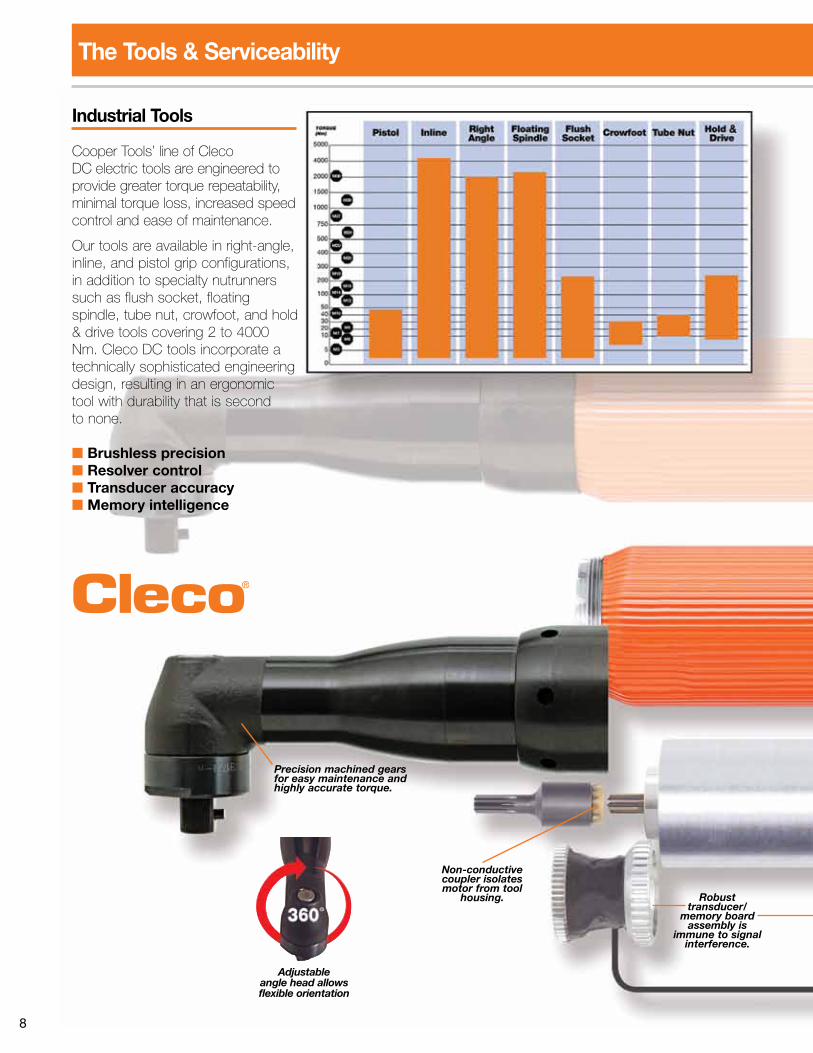
Industrial Tools
Cooper Tools’ line of Cleco DC electric tools are engineered to provide greater torque repeatability, minimal torque loss, increased speed control and ease of maintenance.
Our tools are available in right-angle, inline, and pistol grip configurations, in addition to specialty nutrunners such as flush socket, floating spindle, tube nut, crowfoot, and hold & drive tools covering 2 to 4000 Nm. Cleco DC tools incorporate a technically sophisticated engineering design, resulting in an ergonomic tool with durability that is second to none.
■ Brushless precision■ Resolver control■ Transducer accuracy■ Memory intelligence
Precision machined gears for easy maintenance and highly accurate torque.
Non-conductive coupler isolates motor from tool
housing. Robust transducer/
memory board assembly is
immune to signal interference.
Adjustable angle head allows flexible orientation
The Tools & Serviceability
9
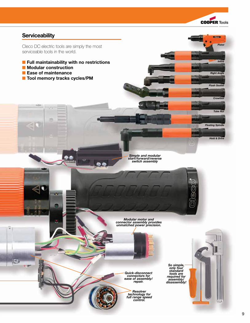
Simple and modular start/forward/reverse
switch assembly
Modular motor and connector assembly provides unmatched power precision.
So simple, only four standard tools are
required for assembly/
disassembly!
Quick-disconnect connectors for
ease of assembly/repair.
Resolver technology for
full range speed control.
Pistol
Inline
Right Angle
Flush Socket
Tube Nut
Crowfoot
Hold & Drive
Floating Spindle
Serviceability
Cleco DC electric tools are simply the most serviceable tools in the world.
■ Full maintainability with no restrictions■ Modular construction■ Ease of maintenance■ Tool memory tracks cycles/PM

10
The Most Cost-Effective Safety Critical Solution Available. Up To 50% Savings Over Traditional Systems!Mobility is a major advantage with wireless communications. Cleco LiveWire™ marries the freedom and flexibility of cordless tools with real-time wireless error proofing. Utilizing an industry standard 2.4GHz WLAN (Wireless Local Area Network) interface in conjunction with the highest security encryption and authentication levels, plus a 512-cycle tool memory buffer, LiveWire™ ensures you will never compromise safety critical data transmissions.
10 Tools.1 Line
Controller.
Electric Nutrunners – Cordless Transducer ControlLiveWire® Wireless Communications
10

11
The Most Cost-Effective Safety Critical Solution Available.
Wireless Security■ WEP (Wired Equivalent Privacy) • 64/128 Bit Encryption HEX (RC4)
■ WPA (Wireless Protected Access)/WPA2/802.11 • 128 Bit TKIP/CCMP Encryption • 802.1x EAP Authentication - LEAP, PEAP, TTLS - GTC, MD5, OTP, PAP, CHAP, MSCHAP, MSCHAPv2, TTLS MSCHAPv2
New! Tethered Productivity!Cleco LiveWire™ tools are now available with Vmax™, a tethered solution that drives continuous tool power and speed increases up to 83% without losing accuracy or durability. This leading innovation utilizes the same 10 tools to one line controller hardware solution with up to 33% cost savings over traditional systems. New Vmax™ technology auto-senses the applied power source and adjusts the maximum tool speed capability on the fly. LiveWire™ with Vmax™ combines the power you need with the most versatile wireless system available today.
Cordless Freedom or Tethered Speed...The Choice Is Yours.
V-max tether is 59% lighter and 46% smaller diameter than traditional cables.
11

12
Low compression
trigger
Low vibration soft grip handle
LiveWire™ offers precision torque, angle and speed control features for safety critical fastening in a lightweight, wireless design.
With up to 1,000 tightening operations per battery charge and quick charge cycles, your safety critical applications are assured to never run out of power.
LiveWire™ has been designed and tested to provide wireless connectivity across the harshest of machine-to-machine environments.
Electronic Intelligence■ On-board controller with power management
■ Integrated servo with I/O signal handling
■ Corded functionality in a cordless solution
High Resolution Resolver■ Rotor position detection
■ Angle control and monitoring for Quality Assurance
■ Full range speed control for operator ergonomics
Battery Technology■ 26V, 1.6 Ah Li-Ion rechargeable battery
■ High power-to-weight technology
■ Up to 1,000 cycles per charge (hard joint)
■ >900 charging cycles
■ Fully charged in 1 hour
Operator Status Display■ Configurable real-time 3 line display
■ Green/Red/Yellow LCD for status
■ 2 configurable application buttons
■ Multiple LED status indicators
All The Brains. All The Power. And It’s Wireless.Electric Nutrunners – Cordless Transducer Control

13
Configurable LED Illumination
Solid metal construction for maximum
durability
Precision Gearing
Reaction Transducer■ Accurate detection of torque via Strain Gage Bridge
■ Torque traceability of safety critical jointsBrushless Motor■ Superior performance with full range speed control
■ Low rotor inertia for high torque accuracy
Digital Audio Interface■ Operator audible alarm
■ Programmable sound duration
All The Brains. All The Power. And It’s Wireless.Integrated Bar Code Scanner (optional)
■ Enables real-time bar code data collection
■ Programmable bit for Auto Parameter Select
■ Tool enable and disable configurability
14
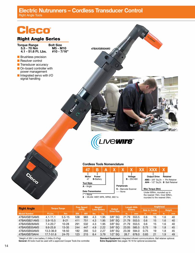
Data Transmission- – NoneX – WLAN: WEP, WPA, WPA2, 802.1x
PeripheralsS – Barcode Scanner - – None
Motor47
Tool StyleA – Angle
PowerB-Battery
47 B A X X X XX XXX X
Max Torque (Nm)
Under 60Nm, rounded up to the nearest 1Nm. Over 60Nm, rounded to the nearest 5Nm.
VoltageB – 26V/48V
Output DriveAM3 – 3/8” Sq.Dr.AH4 – 1/2” Sq.Dr.
Retainer– Pin RetainerB Ball Retainer
Cordless Tools Nomenclature
Electric Nutrunners – Cordless Transducer ControlRight Angle Tools
Right Angle SeriesTorque Range Bolt Size 5.5 - 70 Nm M5 - M10 4.1 - 51.6 Ft. Lbs. #10 - 7/16”
■ Brushless precision■ Resolver control■ Transducer accuracy■ On-board controller with power management■ Integrated servo with I/O signal handling
47BAXSB50AM3
Right Angle Torque Range Free Speed(RPM)
Weight*Less Battery Output
Drive Size
Length With Battery
Anglehead
Side to Center Height
Model Number Ft.Lbs. Nm 26V 48V lbs. kg in. mm in. mm in. mm
47BAXSB15AM3 4.1-11.1 5.5-15 538 983 4.3 1.95 3/8" SQ 21.79 553.5 0.6 15 1.6 4047BAXSB21AM3 5.9-15.5 8-21 411 751 4.3 1.95 3/8" SQ 21.79 553.5 0.6 15 1.6 4047BAXSB28AM3 7.4-20.7 10-28 291 532 4.3 1.95 3/8" SQ 21.79 553.5 0.6 15 1.6 4047BAXSB35AM3 9.6-25.8 13-35 244 447 4.9 2.22 3/8" SQ 23.05 585.5 0.75 19 1.8 4547BAXSB50AM3 13.3-36.9 18-50 182 293 5.0 2.27 3/8" SQ 23.39 594.0 0.75 19 1.8 4547BAXSB70AH4 17.7-51.6 24-70 123 215 8.4 3.79 1/2" SQ 26.7 678.0 0.83 21 1.9 49*Weight of 26V Li-Ion battery (1.04lbs./0.47kg). General: All tools must be used with a approved Cooper Tools line controller.
Standard Equipment: Integrated infrared communications. Ball retainer optional.Extra Equipment: See pages 18-19 for optional accessories.

15
17BPXSB13Q
Data Transmission- – NoneX – WLAN: WEP, WPA, WPA2, 802.1x
PeripheralsS – Barcode Scanner - – None
Motor17
Tool StyleP – Pistol
PowerB-Battery
17 B P X X X XX Q
Max Torque (Nm)
Under 60Nm, rounded up to the nearest 1Nm.
VoltageB – 26V/48V
Output DriveQ – Quick change
Cordless Tools Nomenclature
Electric Nutrunners – Cordless Transducer ControlPistol Grip Tools
Pistol Grip Torque Range Free Speed(RPM)
Weight*Less Battery Output
Drive SizeLength With Battery Side to Center
Model Number Ft.Lbs. Nm 26V 48V lbs. kg in. mm in. mm
17BPXSB05Q 2.2-3.7 3-5 1639 2428 2.8 1.29 1/4" Hex 8.44 214.5 0.71 1817BPXSB07Q 2.2-5.2 3-7 1161 1721 2.8 1.29 1/4" Hex 8.44 214.5 0.71 1817BPXSB09Q 2.2-6.6 3-9 887 1314 2.8 1.29 1/4" Hex 8.44 214.5 0.71 1817BPXSB13Q 2.2-9.6 3-13 629 931 2.8 1.29 1/4" Hex 8.44 214.5 0.71 18*Weight of 26V Li-Ion battery (1.04lbs./0.47kg). General: All tools must be used with a approved Cooper Tools line controller.
Standard Equipment: Integrated infrared communications.Extra Equipment: See pages 18-19 for optional accessories.
Pistol Grip SeriesTorque Range Bolt Size 3.0 - 13 Nm M5 - M6 2.2 - 9.6 Ft. Lbs. #10 - 1/4”
■ Brushless precision■ Resolver control■ Transducer accuracy■ On-board controller with power management■ Integrated servo with I/O signal handling
16
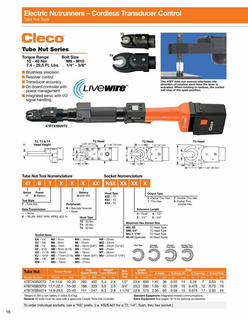
Tube Nut Torque Range FreeSpeed (RPM)
Weight*Less Battery
Max.Drive Size
Length w/Battery
HeadA Width B Blade Ht. C Opening D End/Cntr.
Model Number Ft.Lbs. Nm 26V 48V lbs. kg in. mm in. mm in. mm in. mm in. mm
47BTXSB20T2 7.4-14.6 10-20 260 455 5.4 2.4 1/2" 23.6 600 1.42 36 0.55 14 0.28 7 0.53 1347BTXSB30T3 11.1-22.1 15-30 188 329 5.5 2.5 3/4" 23.3 592 1.65 42 0.59 15 0.475 12 0.73 1947BTXSB40T4 14.8-29.5 20-40 141 247 6.3 2.8 1 1/16" 22.6 575 2.36 60 0.59 15 0.675 17 0.93 24*Weight of 26V Li-Ion battery (1.04lbs./0.47kg). General: All tools must be used with a approved Cooper Tools line controller.
Standard Equipment: Integrated infrared communications.Extra Equipment: See pages 18-19 for optional accessories.
To order individual sockets, use a “KS” prefix. (i.e. KS2EA01 for a T2, 1/4”, flush, thru hex socket.)
“B”T2, T3 & T4Head Height
“A”
2.63” (67 mm) 1.56” (40 mm)T2 Head T3 Head
1.44” (37 mm)
“A”“C”
“D”
T4 Head
1.94” (49 mm)
“A”“C”
“D”
“C”
“D”
T3
T4
Electric Nutrunners – Cordless Transducer ControlTube Nut Tools
Tube Nut SeriesTorque Range Bolt Size 10 - 40 Nm M6 - M10 7.4 - 29.5 Ft. Lbs. 1/4” - 3/8”
■ Brushless precision■ Resolver control■ Transducer accuracy■ On-board controller with power management■ Integrated servo with I/O signal handling
47BTXSB20T2
The 47BT tube nut wrench alternates the direction of rotation each time the lever is actuated. When rotating in reverse, the socket will stop at the open position.
Tube Nut Tool Nomenclature Socket Nomenclature
PeripheralsS – Barcode Scanner - – None
BatteryB-26V-48V
Series47
Tool StyleT – Tube Nut
PowerB–Battery
Output Type
0 -Partial Thru Hex 2 -Double Thru Hex1 -Thru Hex 3 -Partial Thru Double Hex
Extension Length
0 – Flush 4 – 1/2”2 – 1/4” 6 – 3/4”
Maximum Hex Socket Size
MG, EE T2 Head TypeMM, 3/4” T3 Head TypeMU, 1 1/16” T4 Head Type00, ## (Specials) All Head Types
Socket Sizes
EA - 1/4” M5 – 5mm MH – 14mm MP – 22mmEC – 3/8 M6 – 6mm MI – 15mm MQ – 23mmEE – 1/2 MA – 7mm MJ – 16mm (5/8”) MR – 24mm (15/16”)EF – 9/16 MB – 8mm (5/16) MK – 17mm MS – 25mmEH – 11/16 MD – 10mm ML – 18mm MT – 26mmEJ – 13/16 ME – 11mm (7/16) MM – 19mm (3/4”) MU – 27mm (1 1/16”)EK – 7/8 MF – 12mm MN – 20mmEM – 1 MG – 13mm MO – 21mm
47 B T X X X XX KSX XX XX X
Data Transmission- – NoneX – WLAN: WEP, WPA, WPA2, 802.1x Head Type
T2 - 20 NmT3 - 30 NmT4 - 40 Nm
Thru Hex DoubleThru Hex
PartialThru Hex
Partial Thru Double Hex
Head TypeKS2 – T2KS3 – T3KS4 – T4
17
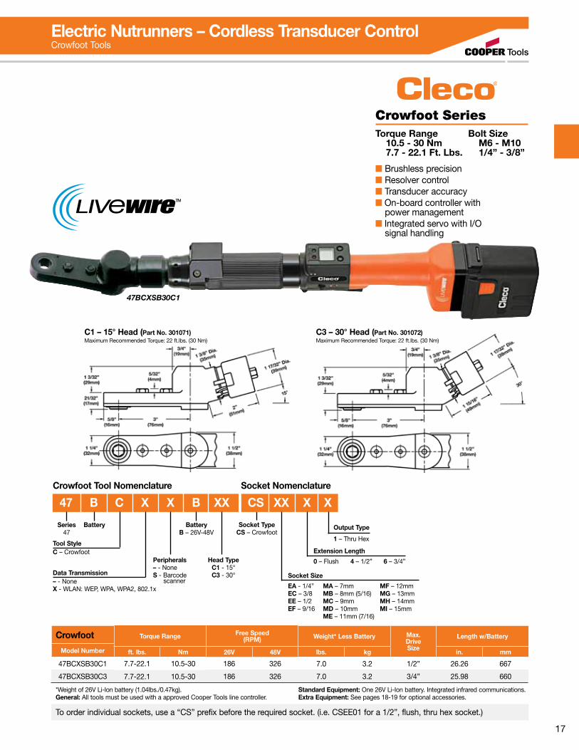
Crowfoot Torque Range Free Speed(RPM) Weight* Less Battery Max.
DriveSize
Length w/Battery
Model Number ft. lbs. Nm 26V 48V lbs. kg in. mm
47BCXSB30C1 7.7-22.1 10.5-30 186 326 7.0 3.2 1/2” 26.26 667
47BCXSB30C3 7.7-22.1 10.5-30 186 326 7.0 3.2 3/4” 25.98 660
*Weight of 26V Li-Ion battery (1.04lbs./0.47kg). General: All tools must be used with a approved Cooper Tools line controller.
Standard Equipment: One 26V Li-Ion battery. Integrated infrared communications.Extra Equipment: See pages 18-19 for optional accessories.
To order individual sockets, use a “CS” prefix before the required socket. (i.e. CSEE01 for a 1/2”, flush, thru hex socket.)
C3 – 30° Head (Part No. 301072)Maximum Recommended Torque: 22 ft.lbs. (30 Nm)
C1 – 15° Head (Part No. 301071)Maximum Recommended Torque: 22 ft.lbs. (30 Nm)
Electric Nutrunners – Cordless Transducer ControlCrowfoot Tools
Crowfoot SeriesTorque Range Bolt Size 10.5 - 30 Nm M6 - M10 7.7 - 22.1 Ft. Lbs. 1/4” - 3/8”
■ Brushless precision■ Resolver control■ Transducer accuracy■ On-board controller with power management■ Integrated servo with I/O signal handling
47BCXSB30C1
Socket TypeCS – Crowfoot
Data Transmission– - NoneX - WLAN: WEP, WPA, WPA2, 802.1x
Peripherals– - NoneS - Barcode scanner
Series47
Tool StyleC – Crowfoot
Battery Output Type
1 – Thru Hex
Extension Length
0 – Flush 4 – 1/2” 6 – 3/4”
Socket Size
EA - 1/4” MA – 7mm MF – 12mmEC – 3/8 MB – 8mm (5/16) MG – 13mmEE – 1/2 MC – 9mm MH – 14mmEF – 9/16 MD – 10mm MI – 15mm ME – 11mm (7/16)
Socket NomenclatureCrowfoot Tool Nomenclature
47 B C X X B XX CS XX X X
Head TypeC1 - 15°C3 - 30°
BatteryB – 26V-48V

18
TMEC Series Tightening Manager Controller■ Multiple channel configurations■ Configurable 24V I/O■ Ethernet TCP/IP standard■ Serial & USB ports standard■ Local storage 50,000 cycles■ High resolution color LCD■ Full programming keypad
Model Number*Features
Weight Width Height Depth
115VAC 230VAC lbs. kg in. mm in. mm in. mm
TMEC-220-15-* TMEC-220-30-* 1-10 channel controller, Ethernet, I/O 13 5.9 11 279.9 17 431.8 5 12.7
T3M-50-N-11-U-DLW 1-10 channel controller, Ethernet, Devicenet, I/O 45 20.4 19 482.6 15 381.0 13 330.2
*Languages offered: D-German, P-Portuguese, S-Spanish, U-English, F-French, I-Italian.Note: See page 78 for T3M specifications.
Controllers
Series Model NumberFree Speed (RPM)
% Increase26V
Battery48V Power
Module
Pis
tol
17BPXSB05Q 1639 2428 48%17BPXSB07Q 1161 1721 48%17BPXSB09Q 887 1314 48%17BPXSB13Q 629 931 48%
Rig
ht A
ngle
47BAXSB15AM3 538 983 83%47BAXSB21AM3 411 751 83%47BAXSB28AM3 291 532 83%47BAXSB35AM3 244 447 83%47BAXSB50AM3 182 293 75%47BAXSB70AH4 123 215 75%
Speed Improvement Comparison
LiveWire Power Module■ Up to 83% faster!■ Auto sensing input – (85-275 VAC)■ Power & status LEDs■ Electronic circuit protection■ Durable metal housing■ Light weight – 6.8lbs. (3.1kg)
Model No.Weight Width Length Depth
lbs. kg in. mm in. mm in. mm
961350 1.5 6.8 9.4 240 4.7 120 5.9 150
2M power cable included.
Power Module
Cordless Tool Controllers & Power Module TMEC & Power Module
TMEC Nomenclature
I/O Channels2 – Dual
Cordless
TME C – 2 2 0 – 15 – U – X X X X
LanguageU – English S – SpanishD – German I – ItalianF – French P – Portuguese
Options for special applications
Model Generation2 – Second
Servo Type0 – None
Voltage15 – 115V30 – 230V
TighteningManagerElectric
19
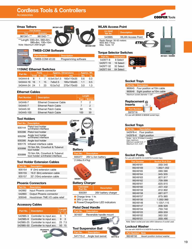
Vmax TethersPart Number
Tool Extension
961341-*** 961342-******Length: 030=3m, 060=6m, 080=8m, 100=10mNote: Maximum 20M length
961341-030
961342-030
For use with 960645 & 960646 socket trays.
Replacement Inserts
S970716 Part Number
Battery Charger115V/220VPart No. Description
935391 26V battery charger
■ Charge time: 1 hr.■ 26V Li-Ion only■ Power/Charge/Error LED indicators
935391
Pistol Dead HandlePart No. Description
301837 Reversible handle mount301837
TMEB-COM Software
Part Number Description
TMEB-COM-V2.03 Programming software
115VAC Ethernet SwitchesPart No.
Ports Approx. Dimensions Approx. Wt.Total In Out in. mm lbs. kg
543444-8 8 1 7 6.5x4.5x1.5 160x110x35 0.6 0.3543444-16 16 1 15 7x6x2.5 185x150x65 1.1 0.5543444-24 24 1 23 10.5x7x2 270x170x50 3.0 1.3
Ethernet Cables
Part Number DescriptionLength
Feet Meters
543446-7 Ethernet Crossover Cable 7 2543445-7 Ethernet Patch Cable 7 2543445-50 Ethernet Patch Cable 50 15543445-100 Ethernet Patch Cable 100 30
Tool Holder Extension CablesPart No. Description
935154 9’ (3m) extension cable935155 19.5’ (6m) extension cable935157 33’ (10m) extension cable
WLAN Access Point
961323 / 593995
2.4 GHZNA No. Description
543995 WLAN Access PointRadio Range: 30-50 metersIEEE 802.11b/gMax. Tools: 10
Socket TraysPart No. Description960645 Four position w/10m cable960646 Eight position w/10m cableMaximum socket diameter 1.125”.
Socket TraysPart No. Description542978-4 Four position542978-8 Eight positionNotes: Up to 16 linked 4 position trays maximum.Minimum socket O.D. 1”.Maximum O.D. 2.25”.
Socket PostsFor use with 542978-4 & 542978-8 socket trays.
Part Number Socket Post Size99249181 .550/.54099249169 1.062/1.05299249165 .590/.58099249164 .945/.93599249163 .827/.81799249162 .709/.69999249161 .625/.61599249160 .437/.43299249159 .812/.80299249158 .687/.67799249157 .875/.86599249156 1.000/.99099249148 1.125/1.11599249147 .938/.92899249104 .750/.74099249103 .669/.65999249102 .562/.55299249101 .500/.490
Note: Select socket post size within tolerance of socket used.
Lockout WasherFor use with 542978-4 & 542978-8 socket trays.
Part Number Note99248150 Vacant position lockout washer
Phoenix ConnectorsPart No. Description
542892 Input Phoenix connector542893 Output Phoenix connector939348 Hood/strain TME I/O cable relief
Torque Selector SwitchesPart No. Description
542977-8 8 Select542977-16 16 Select542977-32 32 Select542977-64 64 Select
Accessory Cable
Accessory Cables
Part No. DescriptionLength
ft. m542985-3 Controller to input acc. 3 1542985-9 Controller to input acc. 9 3542985-25 Controller to input acc. 25 7.5542985-50 Controller to input acc. 50 15
Tool HoldersPart No. Description
935144 Pistol tool holder w/infrared interface
935396 Pistol tool holder
935290 Angle tool holder w/infrared interface
935395 Angle tool holder935170 Infrared interface cable
935998 70 Nm RA, Crowfoot & Tubenut tool holder
935999 70 Nm RA, Crowfoot & Tubenut tool holder w/infrared interface
935290
935170935144
Cordless Tools & ControllersAccessories
541715-2
Tool Suspension BailPart No. Description
541715-2 Angle tool swivel
BatteryPart No. Description
935377 26V Li-Ion battery(1.04lbs./0.47kg)
935377

20
Durability. Speed. Ergonomics.Cleco 18-48 series tools are driven by a new maintenance-free brushless motor with up to 50% more speed and productivity. This new motor technology coupled with our high-resolution resolver offers full range control for safety critical joints. The 18-48 series tools with industry proven gear trains create outstanding durable production performance.
The Cleco 18-48 series electric tools provide a unique modular assembly design for ease of repair. The on-board intelligent memory chip records tool set-up values and counts cycles for maintenance scheduling to prevent costly production downtime.
Highly visible operator feedback LEDs
Intelligent memory
chip
New low compression
switch
New handle for operator comfort
Resolver technology for full range speed control
Tools shown with Apex® u-Guard™ protective covered industrial sockets. Cover spins independently of socket virtually eliminating damages and risks associated with incidental contact between the tool and the workpiece or user. Not included with tool.
Error free connector
Matrix
Electric Nutrunners – Corded Transducer Control

21
Durability. Speed. Ergonomics.Optimal tool weight
and balance
Reaction transducer for consistent torque
repeatability
Standard tools required for service
Durable industry proven
gear train
Tools shown with Apex® u-Guard™ protective covered industrial sockets. Cover spins independently of socket virtually eliminating damages and risks associated with incidental contact between the tool and the workpiece or user. Not included with tool.
Adjustable angle head allows flexible orientationNew low inertia brushless motor
for superior fastening control
22
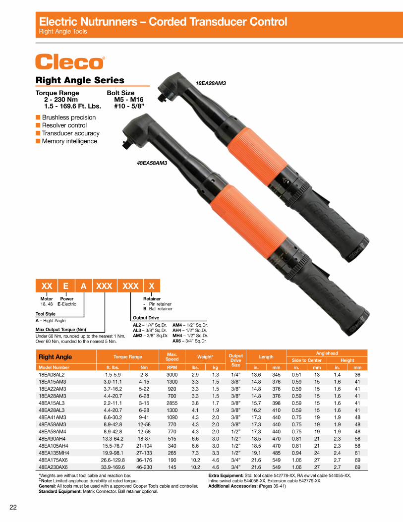
Right Angle Torque Range Max.Speed Weight* Output
DriveSize
LengthAnglehead
Side to Center Height
Model Number ft. lbs. Nm RPM lbs. kg in. mm in. mm in. mm
18EA08AL2 1.5-5.9 2-8 3000 2.9 1.3 1/4” 13.6 345 0.51 13 1.4 3618EA15AM3 3.0-11.1 4-15 1300 3.3 1.5 3/8” 14.8 376 0.59 15 1.6 4118EA22AM3 3.7-16.2 5-22 920 3.3 1.5 3/8” 14.8 376 0.59 15 1.6 4118EA28AM3 4.4-20.7 6-28 700 3.3 1.5 3/8” 14.8 376 0.59 15 1.6 4148EA15AL3 2.2-11.1 3-15 2855 3.8 1.7 3/8” 15.7 398 0.59 15 1.6 4148EA28AL3 4.4-20.7 6-28 1300 4.1 1.9 3/8” 16.2 410 0.59 15 1.6 4148EA41AM3 6.6-30.2 9-41 1090 4.3 2.0 3/8” 17.3 440 0.75 19 1.9 4848EA58AM3 8.9-42.8 12-58 770 4.3 2.0 3/8” 17.3 440 0.75 19 1.9 4848EA58AM4 8.9-42.8 12-58 770 4.3 2.0 1/2” 17.3 440 0.75 19 1.9 4848EA90AH4 13.3-64.2 18-87 515 6.6 3.0 1/2” 18.5 470 0.81 21 2.3 5848EA105AH4 15.5-76.7 21-104 340 6.6 3.0 1/2” 18.5 470 0.81 21 2.3 5848EA135MH4 19.9-98.1 27-133 265 7.3 3.3 1/2” 19.1 485 0.94 24 2.4 6148EA175AX6 26.6-129.8 36-176 190 10.2 4.6 3/4” 21.6 549 1.06 27 2.7 6948EA230AX6 33.9-169.6 46-230 145 10.2 4.6 3/4” 21.6 549 1.06 27 2.7 69
*Weights are without tool cable and reaction bar. ‡Note: Limited anglehead durability at rated torque.General: All tools must be used with a approved Cooper Tools cable and controller.Standard Equipment: Matrix Connector. Ball retainer optional.
Extra Equipment: Std. tool cable 542778-XX, RA swivel cable 544055-XX, Inline swivel cable 544056-XX, Extension cable 542779-XX.Additional Accessories: (Pages 39-41)
Right Angle SeriesTorque Range Bolt Size 2 - 230 Nm M5 - M16 1.5 - 169.6 Ft. Lbs. #10 - 5/8”
■ Brushless precision■ Resolver control■ Transducer accuracy■ Memory intelligence
18EA28AM3
48EA58AM3
Electric Nutrunners – Corded Transducer ControlRight Angle Tools
Max Output Torque (Nm)Under 60 Nm, rounded up to the nearest 1 Nm.Over 60 Nm, rounded to the nearest 5 Nm.
Motor18, 48
Tool StyleA – Right Angle
PowerE-Electric
XX E A XXX XXX X
Output Drive
AL2 – 1/4” Sq.Dr. AM4 – 1/2” Sq.Dr.AL3 – 3/8” Sq.Dr. AH4 – 1/2” Sq.Dr.AM3 – 3/8” Sq.Dr. MH4 – 1/2” Sq.Dr. AX6 – 3/4” Sq.Dr.
Retainer- Pin retainer B Ball retainer
23
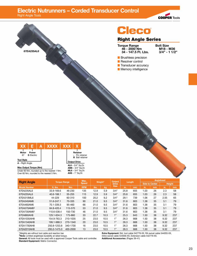
Right Angle Torque Range Max.Speed Weight* Output
DriveSize
LengthAnglehead
Side to Center Height
Model Number ft. lbs. Nm RPM lbs. kg in. mm in. mm in. mm
67EA235AL6 33.9-169.6 46-230 135 12.9 5.9 3/4” 25.8 655 1.03 26 2.3 5867EA255AL6 40.6-188.1 55-255 115 12.9 5.9 3/4” 25.8 655 1.03 26 2.3 5867EA310ML6 44-229 60-310 100 20.2 9.2 3/4” 29.1 739 1.06 27 2.55 6567EA340AM6 51.6-247.1 70-335 90 21.0 9.5 3/4” 31.6 803 1.38 35 3.1 7967EA460AM6 70.1-339.3 95-460 66 21.0 9.5 3/4” 31.6 803 1.38 35 3.1 7967EA570AM6‡ 84.8-420.4 115-570 53 21.0 9.5 3/4” 31.6 803 1.38 35 3.1 7967EA730AM6‡ 110.6-538.4 150-730 46 21.0 9.5 3/4” 31.6 803 1.38 35 3.1 7967EA860AH8 129.1-634.3 175-860 33 22.7 10.3 1” 25.3 643 1.50 38 9.32 23767EA1035AH8 154.9-763.3 210-1035 25 23.0 10.5 1” 26.3 668 1.50 38 9.32 23767EA1340AH8 199.1-988.3 270-1340 20 23.0 10.5 1” 26.3 668 1.50 38 9.32 23767EA1700AH8 250.8-1253.8 340-1700 16 23.0 10.5 1” 26.3 668 1.50 38 9.32 23767EA2010AH8 295.0-1475.0 400-2000 13 23.0 10.5 1” 26.3 668 1.50 38 9.32 237
*Weights are without tool cable and reaction bar. ‡Note: Limited anglehead durability at rated torque.General: All tools must be used with a approved Cooper Tools cable and controller.Standard Equipment: Matrix Connector.
Extra Equipment: Std. tool cable 542778-XX, RA swivel cable 544055-XX, Inline swivel cable 544056-XX, Extension cable 542779-XX.Additional Accessories: (Pages 39-41)
Right Angle SeriesTorque Range Bolt Size 46 - 2000 Nm M18 - M36 34 - 147.5 Ft. Lbs. 3/4” - 1 1/2”
■ Brushless precision■ Resolver control■ Transducer accuracy■ Memory intelligence
67EA235AL6
Electric Nutrunners – Corded Transducer ControlRight Angle Tools
Max Output Torque (Nm)Under 60 Nm, rounded up to the nearest 1 Nm.Over 60 Nm, rounded to the nearest 5 Nm.
Motor67
Tool StyleA – Right Angle
PowerE-Electric
XX E A XXXX XXX X
Output Drive
AL6 – 3/4” Sq.Dr.AM6 – 3/4” Sq.Dr.ML6 – 3/4” Sq.Dr.AH8 – 1” Sq.Dr.
Retainer- Pin retainer B Ball retainer
24
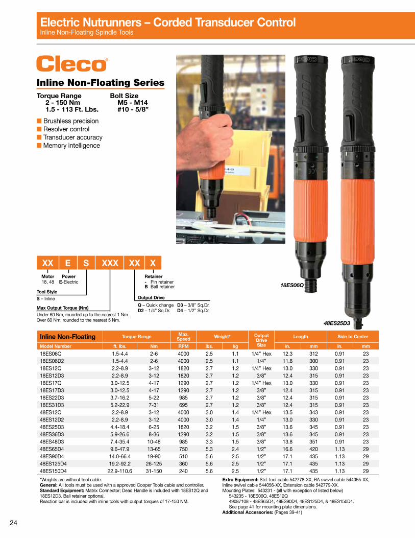
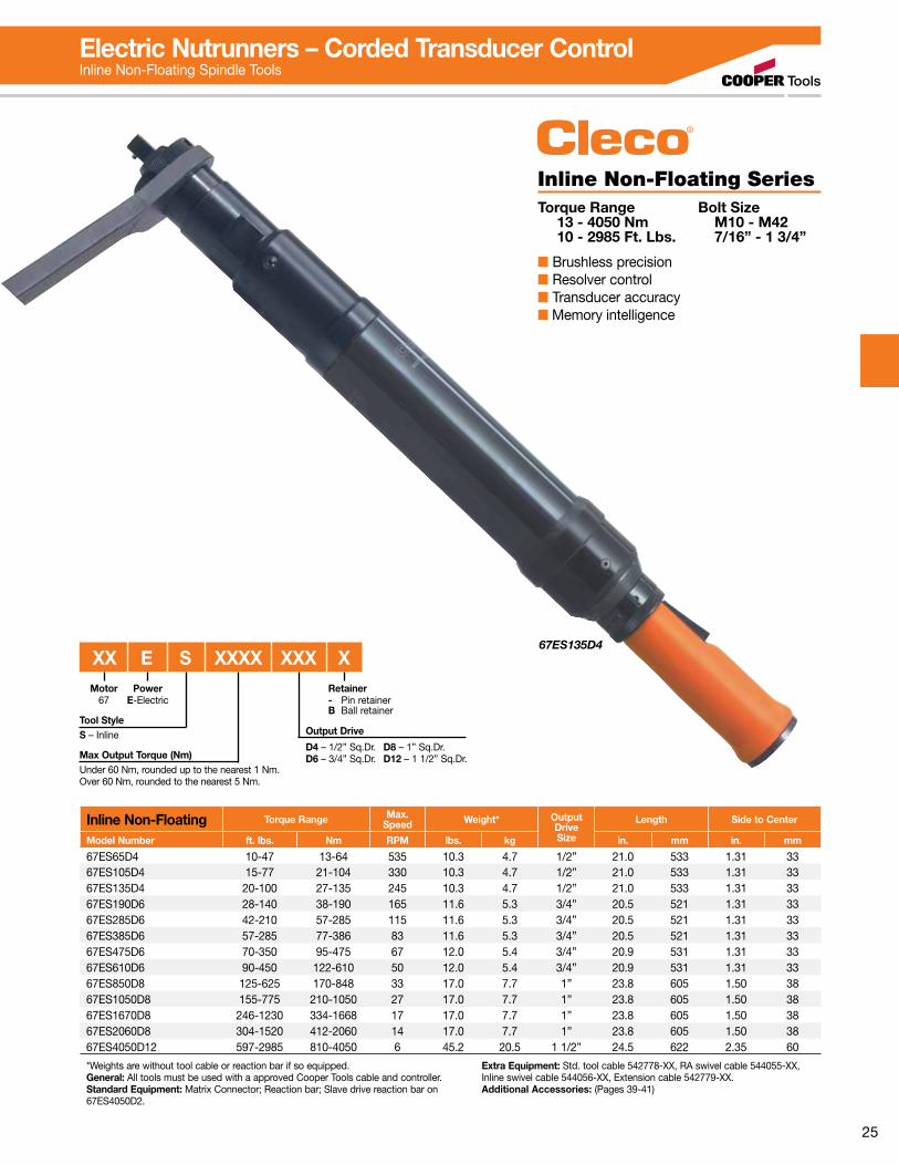
Inline Non-Floating SeriesTorque Range Bolt Size 2 - 150 Nm M5 - M14 1.5 - 113 Ft. Lbs. #10 - 5/8”
■ Brushless precision■ Resolver control■ Transducer accuracy■ Memory intelligence
48ES25D3
18ES06Q
Inline Non-Floating Torque Range Max.Speed Weight* Output
DriveSize
Length Side to Center
Model Number ft. lbs. Nm RPM lbs. kg in. mm in. mm
18ES06Q 1.5-4.4 2-6 4000 2.5 1.1 1/4” Hex 12.3 312 0.91 2318ES06D2 1.5-4.4 2-6 4000 2.5 1.1 1/4” 11.8 300 0.91 2318ES12Q 2.2-8.9 3-12 1820 2.7 1.2 1/4” Hex 13.0 330 0.91 2318ES12D3 2.2-8.9 3-12 1820 2.7 1.2 3/8” 12.4 315 0.91 2318ES17Q 3.0-12.5 4-17 1290 2.7 1.2 1/4” Hex 13.0 330 0.91 2318ES17D3 3.0-12.5 4-17 1290 2.7 1.2 3/8” 12.4 315 0.91 2318ES22D3 3.7-16.2 5-22 985 2.7 1.2 3/8” 12.4 315 0.91 2318ES31D3 5.2-22.9 7-31 695 2.7 1.2 3/8” 12.4 315 0.91 2348ES12Q 2.2-8.9 3-12 4000 3.0 1.4 1/4” Hex 13.5 343 0.91 2348ES12D2 2.2-8.9 3-12 4000 3.0 1.4 1/4” 13.0 330 0.91 2348ES25D3 4.4-18.4 6-25 1820 3.2 1.5 3/8” 13.6 345 0.91 2348ES36D3 5.9-26.6 8-36 1290 3.2 1.5 3/8” 13.6 345 0.91 2348ES48D3 7.4-35.4 10-48 985 3.3 1.5 3/8” 13.8 351 0.91 2348ES65D4 9.6-47.9 13-65 750 5.3 2.4 1/2” 16.6 420 1.13 2948ES90D4 14.0-66.4 19-90 510 5.6 2.5 1/2” 17.1 435 1.13 2948ES125D4 19.2-92.2 26-125 360 5.6 2.5 1/2” 17.1 435 1.13 2948ES150D4 22.9-110.6 31-150 240 5.6 2.5 1/2” 17.1 435 1.13 29
*Weights are without tool cable. General: All tools must be used with a approved Cooper Tools cable and controller.Standard Equipment: Matrix Connector; Dead Handle is included with 18ES12Q and 18ES12D3. Ball retainer optional. Reaction bar is included with inline tools with output torques of 17-150 NM.
Extra Equipment: Std. tool cable 542778-XX, RA swivel cable 544055-XX, Inline swivel cable 544056-XX, Extension cable 542779-XX.Mounting Plates: 543231 - (all with exception of listed below) 543235 - 18ES06Q, 48ES12Q 49087108 - 48ES65D4, 48ES90D4, 48ES125D4, & 48ES150D4. See page 41 for mounting plate dimensions.Additional Accessories: (Pages 39-41)
Electric Nutrunners – Corded Transducer ControlInline Non-Floating Spindle Tools
Max Output Torque (Nm)Under 60 Nm, rounded up to the nearest 1 Nm.Over 60 Nm, rounded to the nearest 5 Nm.
Output Drive
Q – Quick change D3 – 3/8” Sq.Dr.D2 – 1/4” Sq.Dr. D4 – 1/2” Sq.Dr.
Motor18, 48
Tool StyleS – Inline
PowerE-Electric
XX E S XXX XX XRetainer- Pin retainer B Ball retainer
25
Inline Non-Floating Torque Range Max.Speed Weight* Output
DriveSize
Length Side to Center
Model Number ft. lbs. Nm RPM lbs. kg in. mm in. mm
67ES65D4 10-47 13-64 535 10.3 4.7 1/2” 21.0 533 1.31 3367ES105D4 15-77 21-104 330 10.3 4.7 1/2” 21.0 533 1.31 3367ES135D4 20-100 27-135 245 10.3 4.7 1/2” 21.0 533 1.31 3367ES190D6 28-140 38-190 165 11.6 5.3 3/4” 20.5 521 1.31 3367ES285D6 42-210 57-285 115 11.6 5.3 3/4” 20.5 521 1.31 3367ES385D6 57-285 77-386 83 11.6 5.3 3/4” 20.5 521 1.31 3367ES475D6 70-350 95-475 67 12.0 5.4 3/4” 20.9 531 1.31 3367ES610D6 90-450 122-610 50 12.0 5.4 3/4” 20.9 531 1.31 3367ES850D8 125-625 170-848 33 17.0 7.7 1” 23.8 605 1.50 3867ES1050D8 155-775 210-1050 27 17.0 7.7 1” 23.8 605 1.50 3867ES1670D8 246-1230 334-1668 17 17.0 7.7 1” 23.8 605 1.50 3867ES2060D8 304-1520 412-2060 14 17.0 7.7 1” 23.8 605 1.50 3867ES4050D12 597-2985 810-4050 6 45.2 20.5 1 1/2” 24.5 622 2.35 60
*Weights are without tool cable or reaction bar if so equipped. General: All tools must be used with a approved Cooper Tools cable and controller.Standard Equipment: Matrix Connector; Reaction bar; Slave drive reaction bar on 67ES4050D2.
Extra Equipment: Std. tool cable 542778-XX, RA swivel cable 544055-XX, Inline swivel cable 544056-XX, Extension cable 542779-XX.Additional Accessories: (Pages 39-41)
Inline Non-Floating SeriesTorque Range Bolt Size 13 - 4050 Nm M10 - M42 10 - 2985 Ft. Lbs. 7/16” - 1 3/4”
■ Brushless precision■ Resolver control■ Transducer accuracy■ Memory intelligence
67ES135D4
Electric Nutrunners – Corded Transducer ControlInline Non-Floating Spindle Tools
Max Output Torque (Nm)Under 60 Nm, rounded up to the nearest 1 Nm.Over 60 Nm, rounded to the nearest 5 Nm.
Output Drive
D4 – 1/2” Sq.Dr. D8 – 1” Sq.Dr.D6 – 3/4” Sq.Dr. D12 – 1 1/2” Sq.Dr.
Motor67
Tool StyleS – Inline
PowerE-Electric
XX E S XXXX XXX XRetainer- Pin retainerB Ball retainer

26
Pistol Grip Torque Range Max.Speed Weight* Output
DriveSize
Length Side to Center
Model Number ft. lbs. Nm RPM lbs. kg in. mm in. mm
18EP06Q 1.5-4.4 2-6 4000 2.2 1.0 1/4” Hex 7.0 178 0.84 2118EP06D2 1.5-4.4 2-6 4000 2.2 1.0 1/4” 6.5 165 0.84 2118EP12Q 2.2-8.9 3-12 1820 2.4 1.1 1/4” Hex 7.7 196 0.84 2118EP12D3 2.2-8.9 3-12 1820 2.4 1.1 3/8” 7.2 183 0.84 2118EP17Q 3.0-12.5 4-17 1290 2.4 1.1 1/4” Hex 7.7 196 0.84 2118EP17D3 3.0-12.5 4-17 1290 2.4 1.1 3/8” 7.2 183 0.84 2118EP22D3 3.7-16.2 5-22 985 2.4 1.1 3/8” 7.2 183 0.84 2118EP31D3 5.2-22.9 7-31 695 2.4 1.1 3/8” 7.2 183 0.84 2148EP12Q 2.2-8.9 3-12 4000 2.7 1.2 1/4” Hex 8.2 208 0.84 2148EP12D2 2.2-8.9 3-12 4000 2.7 1.2 1/4” 7.7 196 0.84 2148EP25D3 3.7-18.4 5-25 1820 2.9 1.3 3/8” 8.4 213 0.84 2148EP36D3 5.9-26.6 8-36 1290 2.9 1.3 3/8” 8.4 213 0.84 2148EP48D3 7.4-35.4 10-48 985 3.0 1.4 3/8” 8.6 218 0.84 2148EP65D4 9.6-47.9 13-65 750 5.0 2.3 1/2” 11.4 290 1.1 2848EP90D4 14.0-66.4 19-90 510 5.3 2.4 1/2” 12.0 305 1.1 2848EP125D4 19.2-92.2 26-125 360 5.3 2.4 1/2” 12.0 305 1.1 2848EP150D4 22.9-110.6 31-150 240 5.3 2.4 1/2” 12.0 305 0.9 23
*Weights are without tool cable or suspension bail. General: All tools must be used with a approved Cooper Tools cable and controller.Standard Equipment: Matrix Connector; Suspension Bail; Dead Handle is included with 18EP12Q & 18EP12D3. Reaction bar is included with pistol tools with output torques of 17-150 Nm. Ball retainer optional.
Extra Equipment: Std. tool cable 542778-XX, RA swivel cable 544055-XX, Inline swivel cable 544056-XX, Extension cable 542779-XX.Additional Accessories: (Pages 39-41)
Pistol Grip SeriesTorque Range Bolt Size 2 - 150 Nm M5 - M14 1.5 - 113 Ft. Lbs. #10 - 5/8”
■ Brushless precision■ Resolver control■ Transducer accuracy■ Memory intelligence
18EP12Q
48EP25D3
Electric Nutrunners – Corded Transducer ControlPistol Grip Tools
Max Output Torque (Nm)Under 60 Nm, rounded up to the nearest 1 Nm.Over 60 Nm, rounded to the nearest 5 Nm.
Motor18, 48
Tool StyleP – Pistol
PowerE-Electric
XX E P XXX XX PRetainer- Pin retainer B Ball retainer
Output Drive
Q – Quick change D3 – 3/8” Sq.Dr.D2 – 1/4” Sq.Dr. D4 – 1/2” Sq.Dr.

27
Push-to-Start SeriesTorque Range Bolt Size 2 - 12 Nm M5 - M6 1.5 - 8.9 Ft. Lbs. #10 - 1/4”
■ Brushless precision■ Resolver control■ Transducer accuracy■ Memory intelligence
Push-to-Start Torque Range Max.Speed Weight* Output
DriveSize
Length Side to Center
Model Number ft. lbs. Nm RPM lbs. kg in. mm in. mm
18EP06QP 1.5-4.4 2-6 4000 2.66 1.19 1/4” Hex 9.35 238 0.84 2118EP06D3P 2.2-8.9 3-12 4000 2.66 1.19 3/8” 8.8 224 0.84 2118EP12QP 2.2-8.9 3-12 1820 2.83 1.27 1/4” Hex 9.35 196 0.84 2118EP12D3P 2.2-8.9 3-12 1820 2.83 1.27 3/8” 8.8 224 0.84 2118ES06QP 1.5-4.4 2-6 4000 2.93 1.31 1/4” Hex 14.75 375 0.91 2318ES06D3P 2.2-8.9 3-12 4000 2.93 1.31 3/8” 14.20 360 0.91 2318ES12QP 2.2-8.9 3-12 1820 3.10 1.40 1/4” Hex 14.75 375 0.91 2318ES12D3P 2.2-8.9 3-12 1820 3.10 1.40 3/8” 14.20 360 0.91 23
*Weights are without tool cable or suspension bail. General: All tools must be used with a approved Cooper Tools cable and controller.Standard Equipment: Matrix Connector; Suspension Bail (pistol only); Dead Handle (301857) is included with 18CPE12Q & 18CPE12D3.
Extra Equipment: Std. tool cable 542778-XX, RA swivel cable 544055-XX, Inline swivel cable 544056-XX, Extension cable 542779-XX.Additional Accessories: (Pages 39-41)
18EP06QP
18ES06QP
Electric Nutrunners – Corded Transducer ControlPush-to-Start Pistol Grip/Inline Tools
Max Output Torque (Nm)Under 60 Nm, rounded up to the nearest 1 Nm.
Output Drive
Q – Quick changeD3 – 3/8” Sq.Dr.
Motor18
Tool StyleP – PistolS – Inline
PowerE-Electric
XX E X XX XX PPush-to-Start

28
Inline Floating Spindle SeriesTorque Range Bolt Size 2 - 248 Nm M5 - M16 1.5 - 182.9 Ft. Lbs. #10 - 5/8”
■ Brushless precision■ Resolver control■ Transducer accuracy■ Memory intelligence
Inline Floating Spindle Torque Range Max.
Speed Weight* OutputDriveSize
Length Side to Center
Model Number ft. lbs. Nm RPM lbs. kg in. mm in. mm
18ES06ZA 1.5-4.4 2-6 4000 3.0 1.4 1/4 15.5 394 0.91 2318ES12ZA 2.2-8.9 3-12 1820 3.2 1.5 1/4 16.0 406 0.91 2318ES17ZA 3.0-12.5 4-17 1290 3.2 1.5 1/4 16.0 406 0.91 23 48ES12ZA 2.2-8.9 3-12 4000 3.4 1.5 1/4 16.7 425 0.91 2348ES271ZB 5.9-19.9 8-27 1820 5.8 2.6 3/8 22.0 559 0.92 2348ES361ZB 5.2-26.6 7-36 1290 5.8 2.6 3/8 22.0 559 0.92 23 48ES602ZB 8.1-42.0 11-57 855 8.4 3.8 1/2 24.4 620 1.10 2848ES702ZB 10.3-50.2 14-68 570 8.4 3.8 1/2 24.4 620 1.10 2848ES802ZB 12.5-60.5 17-82 450 9.6 4.4 1/2 26.7 678 1.10 3148ES1152ZB 18.4-84.8 25-115 320 9.6 4.4 1/2 26.7 678 1.10 3148ES1502ZB 22.9-110.6 31-150 245 9.6 4.4 1/2 26.7 678 1.10 3148ES1653ZB 24.3-121.7 33-165 220 14.6 6.6 3/4 28.6 726 1.57 4048ES2503ZB 36.8-182.9 50-248 145 14.6 6.6 3/4 28.6 726 1.57 40
*Weights are without tool cable or reaction bar if so equipped. General: All tools must be used with a approved Cooper Tools cable and controller.Standard Equipment: Matrix Connector. Tools have thru hole output.
Extra Equipment: Std. tool cable 542778-XX, RA swivel cable 544055-XX, Inline swivel cable 544056-XX, Extension cable 542779-XX.Additional Accessories: (Pages 39-41)
48ES12ZA
1.22”58.87mm
2.318”
1.159”29.43mm
.669”16.99mm
1.339”34.01mm
3.15”80.01mm
31.1mm
1ZBZA 2ZB 3ZB
Dimensional Spindle Float: 1” (25mm) ZA 2” (50mm) 1ZB, 2ZB, 3ZB
tolerances = ± .004” (0.1mm)
0.25”6.3mm
1.22”31.1mm 1.31”
33.3mm1.73”
44.0mm
0.35”9.0mm
1.37”34.9mm
1.41”35.92mm
1.41”35.92mm
2.00”50.8mm
1.97”50.04mm
.56”14.22mm
1.50”38.1mm
1.10”27.94mm
M5 x 0.8Thd. Typ.
Base Plate Mounting Dimensions
Electric Nutrunners – Corded Transducer ControlInline Floating Spindle Tools
Motor18, 48
Tool StyleS – Inline
Electric
XX E S XXX XXX
Output Drive
ZA – 1/4” Sq.Dr.1ZB – 3/8” Sq.Dr.2ZB – 1/2” Sq.Dr.3ZB – 3/4” Sq.Dr.
Max Output Torque (Nm)Under 60 Nm, rounded up to the nearest 1 Nm.Over 60 Nm, rounded to the nearest 5 Nm.
29
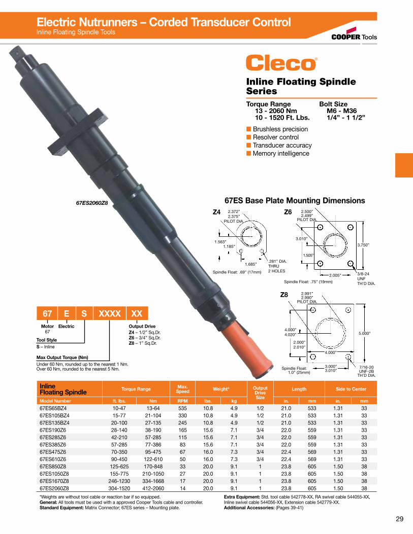
67ES2060Z8
Inline Floating Spindle Torque Range Max.
Speed Weight* OutputDriveSize
Length Side to Center
Model Number ft. lbs. Nm RPM lbs. kg in. mm in. mm
67ES65BZ4 10-47 13-64 535 10.8 4.9 1/2 21.0 533 1.31 3367ES105BZ4 15-77 21-104 330 10.8 4.9 1/2 21.0 533 1.31 3367ES135BZ4 20-100 27-135 245 10.8 4.9 1/2 21.0 533 1.31 3367ES190Z6 28-140 38-190 165 15.6 7.1 3/4 22.0 559 1.31 3367ES285Z6 42-210 57-285 115 15.6 7.1 3/4 22.0 559 1.31 3367ES385Z6 57-285 77-386 83 15.6 7.1 3/4 22.0 559 1.31 3367ES475Z6 70-350 95-475 67 16.0 7.3 3/4 22.4 569 1.31 3367ES610Z6 90-450 122-610 50 16.0 7.3 3/4 22.4 569 1.31 3367ES850Z8 125-625 170-848 33 20.0 9.1 1 23.8 605 1.50 3867ES1050Z8 155-775 210-1050 27 20.0 9.1 1 23.8 605 1.50 3867ES1670Z8 246-1230 334-1668 17 20.0 9.1 1 23.8 605 1.50 3867ES2060Z8 304-1520 412-2060 14 20.0 9.1 1 23.8 605 1.50 38
*Weights are without tool cable or reaction bar if so equipped. General: All tools must be used with a approved Cooper Tools cable and controller.Standard Equipment: Matrix Connector; 67ES series – Mounting plate.
Extra Equipment: Std. tool cable 542778-XX, RA swivel cable 544055-XX, Inline swivel cable 544056-XX, Extension cable 542779-XX.Additional Accessories: (Pages 39-41)
Inline Floating Spindle SeriesTorque Range Bolt Size 13 - 2060 Nm M6 - M36 10 - 1520 Ft. Lbs. 1/4” - 1 1/2”
■ Brushless precision■ Resolver control■ Transducer accuracy■ Memory intelligence
67ES Base Plate Mounting Dimensions
Spindle Float: .69” (17mm)
2.372”2.375”
PILOT DIA.
1.185”
.281” DIA.THRU 2 HOLES
1.685”
1.563”
Z4
2.005”
3.010”
1.505”
3/8-24 UNF TH'D DIA.
3.750”
2.500”2.499”
PILOT DIA.
Z6
Spindle Float: .75” (19mm)
4.000”4.020”
7/16-20 UNF-2B
TH’D DIA.
5.000”
4.000”
2.000”2.010”
3.000”3.010”
2.991”2.990”
PILOT DIA.
Z8
Spindle Float: 1.0” (25mm)
Electric Nutrunners – Corded Transducer ControlInline Floating Spindle Tools
Motor67
Tool StyleS – Inline
Electric
67 E S XXXX XXOutput DriveZ4 – 1/2” Sq.Dr.Z6 – 3/4” Sq.Dr.Z8 – 1” Sq.Dr.
Max Output Torque (Nm)Under 60 Nm, rounded up to the nearest 1 Nm.Over 60 Nm, rounded to the nearest 5 Nm.

30
Hold & Drive Torque Range FreeSpeed Length Weight* Head Height Side to Center
Model Number Ft.Lbs. Nm RPM in. mm lbs. kg in. mm in. mm
48EA53H 8.1 – 39.1 11 – 53 850 20.2 512 7.9 3.60 2.40 61 1.06 2748EA75H 11.1 – 54.6 15 – 74 600 20.2 512 7.9 4.03 2.40 61 1.06 2748EA110H 17.0 – 82.6 23 – 112 400 20.2 512 8.9 4.03 2.40 61 1.06 2748EA135H 20.7 – 98.8 28 – 134 270 20.6 522 8.9 4.03 2.40 61 1.06 2748EA230H 34.7 – 167.4 47 – 227 150 22.2 563 10.6 4.79 2.40 61 1.06 27
*Weights are without tool cable and reaction bar. General: All tools must be used with a approved Cooper Tools cable and controller.Standard Equipment: Matrix Connector. Retraction 1” standard for hold bit.
Extra Equipment: Std. tool cable 542778-XX, RA swivel cable 544055-XX, Inline swivel cable 544056-XX, Extension cable 542779-XX.Additional Accessories: (Pages 39-41)
Hold & Drive SeriesTorque Range 11 - 227 Nm 8.1 - 167.4 Ft. Lbs. ■ Brushless precision■ Resolver control■ Transducer accuracy■ Memory intelligence
48EA115H
Electric Nutrunners – Corded Transducer ControlHold & Drive Tools
48 E A XXX H H X XX X XX XHold & Drive Tool Nomenclature Socket Nomenclature
Max Output Torque
<60 Nm, rounded up to the nearest 1 Nm. >60 Nm, rounded to the nearest 5 Nm.
Retainer Shaft
3 - 3 1/2”4 - 4”5 - 5 3/8”6 - 5 7/8”9 - 9 1/2”
Head TypeH-Hold & Drive
Motor48
Tool Style
A – Angle
Electric
Drive Socket Sizes (surface drive)
EH – 11/16 MG – 13mm MM – 19mm (3/4”) MS – 25mmEJ – 13/16 MH – 14mm MN – 20mm MT – 26mmEK – 7/8 MI – 15mm MO – 21mm MU – 27mm (1 1/16”)EM – 1 MJ – 16mm (5/8”) MP – 22mm MX – 30mm (1 3/16”)EO – 1 1/8 MK – 17mm MQ – 23mm MZ – 32mm (1 1/4”) ML – 18mm MR – 24mm (15/16”)
Hold & Drive
Oval Dim. (length)If socket style =0 (female oval)
Socket Style
F – Female HexM – Male HexT – TorxO – Female Oval Hold Socket (width across flats)
EA – 1/4 ME – 11mm (7/16”)EC – 3/8 MF – 12mmM5 – 5mm 15 – T15M6 – 6mm 20 – T20MA – 7mm 25 – T25MB – 8mm (5/16”) 30 – T30MC – 9mm 40 – T40MD – 10mm 45 – T45 50 – T50
Male Oval (length)
Hold Size (width)
Output Drive Size
31
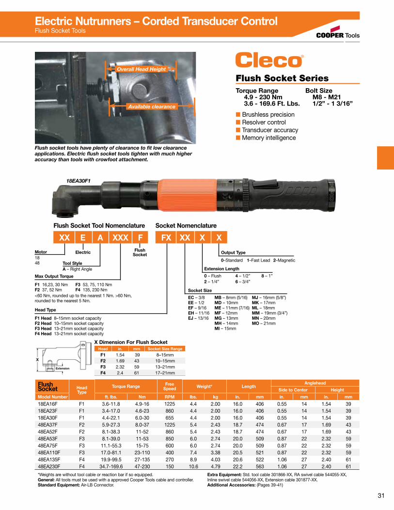
Flush Socket SeriesTorque Range Bolt Size 4.9 - 230 Nm M8 - M21 3.6 - 169.6 Ft. Lbs. 1/2” - 1 3/16”
■ Brushless precision■ Resolver control■ Transducer accuracy■ Memory intelligence
18EA30F1
Flush socket tools have plenty of clearance to fit low clearance applications. Electric flush socket tools tighten with much higher accuracy than tools with crowfoot attachment.
Overall Head Height
Available clearance
Electric Nutrunners – Corded Transducer ControlFlush Socket Tools
Flush Socket Head
TypeTorque Range Free
Speed Weight* LengthAnglehead
Side to Center Height
Model Number ft. lbs. Nm RPM lbs. kg in. mm in. mm in. mm
18EA16F F1 3.6-11.8 4.9-16 1225 4.4 2.00 16.0 406 0.55 14 1.54 3918EA23F F1 3.4-17.0 4.6-23 860 4.4 2.00 16.0 406 0.55 14 1.54 3918EA30F F1 4.4-22.1 6.0-30 655 4.4 2.00 16.0 406 0.55 14 1.54 3948EA37F F2 5.9-27.3 8.0-37 1225 5.4 2.43 18.7 474 0.67 17 1.69 4348EA52F F2 8.1-38.3 11-52 860 5.4 2.43 18.7 474 0.67 17 1.69 4348EA53F F3 8.1-39.0 11-53 850 6.0 2.74 20.0 509 0.87 22 2.32 5948EA75F F3 11.1-55.3 15-75 600 6.0 2.74 20.0 509 0.87 22 2.32 5948EA110F F3 17.0-81.1 23-110 400 7.4 3.38 20.5 521 0.87 22 2.32 5948EA135F F4 19.9-99.5 27-135 270 8.9 4.03 20.6 522 1.06 27 2.40 6148EA230F F4 34.7-169.6 47-230 150 10.6 4.79 22.2 563 1.06 27 2.40 61
*Weights are without tool cable or reaction bar if so equipped. General: All tools must be used with a approved Cooper Tools cable and controller.Standard Equipment: Air-LB Connector.
Extra Equipment: Std. tool cable 301866-XX, RA swivel cable 544055-XX, Inline swivel cable 544056-XX, Extension cable 301877-XX.Additional Accessories: (Pages 39-41)
FX XX X X
Head Type
F1 Head 8–15mm socket capacityF2 Head 10–15mm socket capacityF3 Head 13–21mm socket capacityF4 Head 13–21mm socket capacity
Motor1848 Tool Style
A – Right Angle
Electric Output Type
0–Standard 1–Fast Lead 2–Magnetic
Extension Length
0 – Flush 4 – 1/2” 8 – 1”2 – 1/4” 6 – 3/4”
Flush Socket Tool Nomenclature Socket Nomenclature
XX E A XXX F
Socket Size
EC – 3/8 MB – 8mm (5/16) MJ – 16mm (5/8”)EE – 1/2 MD – 10mm MK – 17mmEF – 9/16 ME – 11mm (7/16) ML – 18mmEH – 11/16 MF – 12mm MM – 19mm (3/4”)EJ – 13/16 MG – 13mm MN – 20mm MH – 14mm MO – 21mm MI – 15mm
X Dimension For Flush SocketHead in. mm Socket Size Range
F1 1.54 39 8–15mmF2 1.69 43 10–15mmF3 2.32 59 13–21mmF4 2.4 61 17–21mm
Max Output Torque
F1 16,23, 30 Nm F3 53, 75, 110 NmF2 37, 52 Nm F4 135, 230 Nm<60 Nm, rounded up to the nearest 1 Nm. >60 Nm, rounded to the nearest 5 Nm.
Flush Socket
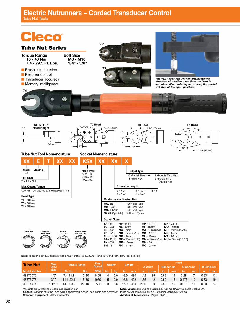
32
T2
T3
T4
“B”T2, T3 & T4Head Height
“A”
2.63” (67 mm) 1.56” (40 mm)T2 Head T3 Head
1.44” (37 mm)
“A”“C”
“D”
T4 Head
1.94” (49 mm)
“A”“C”
“D”
“C”
“D”
Tube Nut Max.DriveSize
Torque Range FreeSpeed Weight* Length
Head
A Width B Blade Ht. C Opening D End/Cntr.
Model Number Ft.Lbs. Nm RPM lbs. kg in. mm in. mm in. mm in. mm in. mm
48ET20T2 1/2” 7.4-14.8 10-20 1425 4.4 2.0 16.9 430 1.42 36 0.55 14 0.28 7 0.53 1348ET30T3 3/4” 11.1-22.1 15-30 1030 4.5 2.0 16.6 422 1.65 42 0.59 15 0.475 13 0.73 1948ET40T4 1 1/16” 14.8-29.5 20-40 770 5.3 2.3 17.9 454 2.36 60 0.59 15 0.675 18 0.93 24
*Weights are without tool cable and reaction bar. General: All tools must be used with a approved Cooper Tools cable and controller.Standard Equipment: Matrix Connector.
Extra Equipment: Std. tool cable 542778-XX, RA swivel cable 544055-XX, Inline swivel cable 544056-XX, Extension cable 542779-XX.Additional Accessories: (Pages 39-41)
Tube Nut SeriesTorque Range Bolt Size 10 - 40 Nm M6 - M10 7.4 - 29.5 Ft. Lbs. 1/4” - 3/8”
■ Brushless precision■ Resolver control■ Transducer accuracy■ Memory intelligence
The 48ET tube nut wrench alternates the direction of rotation each time the lever is actuated. When rotating in reverse, the socket will stop at the open position.
Note: To order individual sockets, use a “KS” prefix (i.e. KS2EA01 for a T2 1/4”, Flush, Thru Hex socket.)
Electric Nutrunners – Corded Transducer ControlTube Nut Tools
Tube Nut Tool Nomenclature Socket Nomenclature
Max Output Torque<60 Nm, rounded up to the nearest 1 Nm.
Head TypeT2 - 20 NmT3 - 30 NmT4 - 40 Nm
Motor48
Tool StyleT – Tube Nut
Electric Output Type
0 -Partial Thru Hex 2 -Double Thru Hex1 -Thru Hex 3 -Partial Thru Double Hex
Extension Length
0 – Flush 4 – 1/2” 8 – 1”2 – 1/4” 6 – 3/4”
Maximum Hex Socket Size
MG, EE T2 Head TypeMM, 3/4” T3 Head TypeMU, 1 1/16” T4 Head Type00, ## (Specials) All Head Types
Thru Hex DoubleThru Hex
PartialThru Hex
Partial Thru Double Hex
Head TypeKS2 – T2KS3 – T3KS4 – T4
XX E T XX XX KSX XX XX X
Socket Sizes
EA - 1/4” M5 – 5mm MH – 14mm MP – 22mmEC – 3/8 M6 – 6mm MI – 15mm MQ – 23mmEE – 1/2 MA – 7mm MJ – 16mm (5/8) MR – 24mm (15/16)EF – 9/16 MB – 8mm (5/16) MK – 17mm MS – 25mmEH – 11/16 MD – 10mm ML – 18mm MT – 26mmEJ – 13/16 ME – 11mm (7/16) MM – 19mm (3/4) MU – 27mm (1 1/16)EK – 7/8 MF – 12mm MN – 20mmEM – 1 MG – 13mm MO – 21mm
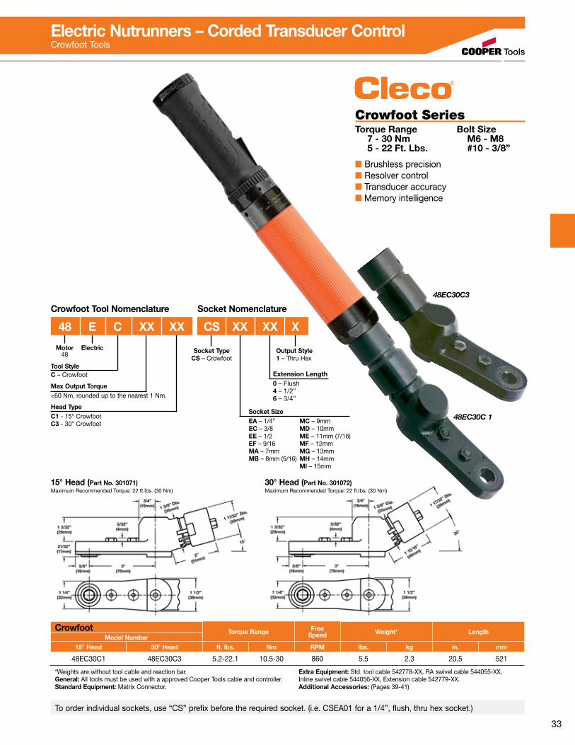
33
15° Head (Part No. 301071)Maximum Recommended Torque: 22 ft.lbs. (30 Nm)
30° Head (Part No. 301072)Maximum Recommended Torque: 22 ft.lbs. (30 Nm)
48EC30C3
48EC30C 1
Crowfoot Torque Range FreeSpeed Weight* Length
Model Number15° Head 30° Head ft. lbs. Nm RPM lbs. kg in. mm
48EC30C1 48EC30C3 5.2-22.1 10.5-30 860 5.5 2.3 20.5 521
*Weights are without tool cable and reaction bar. General: All tools must be used with a approved Cooper Tools cable and controller.Standard Equipment: Matrix Connector.
Extra Equipment: Std. tool cable 542778-XX, RA swivel cable 544055-XX, Inline swivel cable 544056-XX, Extension cable 542779-XX.Additional Accessories: (Pages 39-41)
To order individual sockets, use “CS” prefix before the required socket. (i.e. CSEA01 for a 1/4”, flush, thru hex socket.)
Crowfoot SeriesTorque Range Bolt Size 7 - 30 Nm M6 - M8 5 - 22 Ft. Lbs. #10 - 3/8”
■ Brushless precision■ Resolver control■ Transducer accuracy■ Memory intelligence
Electric Nutrunners – Corded Transducer ControlCrowfoot Tools
Max Output Torque<60 Nm, rounded up to the nearest 1 Nm.
Head TypeC1 - 15° CrowfootC3 - 30° Crowfoot
Motor48
Tool StyleC – Crowfoot
Electric
Socket SizeEA – 1/4” MC – 9mmEC – 3/8 MD – 10mmEE – 1/2 ME – 11mm (7/16)EF – 9/16 MF – 12mmMA – 7mm MG – 13mmMB – 8mm (5/16) MH – 14mm MI – 15mm
Socket NomenclatureCrowfoot Tool Nomenclature
Output Style1 – Thru Hex
Socket TypeCS – Crowfoot
Extension Length0 – Flush4 – 1/2”6 – 3/4”
48 E C XX XX CS XX XX X

34
Right Angle Floating Spindle SeriesTorque Range Bolt Size 5.1 - 255 Nm M7 - M18 3.7 - 188.1 Ft. Lbs. 1/4” - 3/4”
■ Brushless precision■ Resolver control■ Transducer accuracy■ Memory intelligence
Right Angle Floating Spindle Torque Range Max.
Speed Weight* OutputDriveSize
Length Side to Center
Model Number ft. lbs. Nm RPM lbs. kg in. mm in. mm
18EA16S131 3.7-11.8 5.1-16 1225 4.4 2.00 3/8” 16.0 406 0.55 1418EA23S131 5.3-16.9 7.2-23 860 4.4 2.00 3/8” 16.0 406 0.55 1418EA30S131 4.4-22.1 6.0-30 655 4.4 2.00 3/8” 16.0 406 0.55 1448EA37S231 5.9-27.2 8.0-37 1225 5.4 2.43 3/8” 18.7 474 0.67 1748EA52S231 8.1-38.3 11-52 860 5.4 2.43 3/8” 18.7 474 0.67 1748EA53S341 8.1-39.1 11-53 850 6.0 2.74 1/2” 20.0 509 0.87 2248EA75S341 11.0-55.3 15-75 600 6.0 2.74 1/2” 20.0 509 0.87 2248EA95S341 14.7-70.0 20-95 460 7.4 3.38 1/2” 20.5 521 0.87 2248EA110S341 16.9-81.1 23-110 400 7.4 3.38 1/2” 20.5 521 0.87 2248EA135S461 20.6-99.5 28-135 270 8.9 4.03 3/4” 20.6 522 1.06 2748EA230S461 34.6-169.6 47-230 150 10.6 4.79 3/4” 22.2 563 1.06 2767EA150S461 22.1-110.6 30-150 210 12.9 5.90 3/4” 25.8 655 1.03 2667EA185S461 27.3-136.3 37-185 170 12.9 5.90 3/4” 25.8 655 1.03 2667EA210S461 31.0-154.8 42-210 155 12.9 5.90 3/4” 25.8 655 1.03 2667EA235S461 33.9-169.6 46-230 135 12.9 5.90 3/4” 25.8 655 1.03 2667EA255S461 40.6-188.1 55-255 115 12.9 5.90 3/4” 25.8 655 1.03 26
*Weights are without tool cable and mounting plate. General: All tools must be used with a approved Cooper Tools cable and controller.Standard Equipment: Matrix Connector; Mounting plate.
Extra Equipment: Std. tool cable 542778-XX, RA swivel cable 544055-XX, Inline swivel cable 544056-XX, Extension cable 542779-XX.Additional Accessories: (Pages 39-41)
48EA135S461
Max Output Torque
S1 Head – 16, 23, or 30 NmS2 Head – 37 or 52 NmS3 Head – 53, 75, 95, or 110 NmS4 Head – 135 or 230 Nm (48 series)S4 Head – 150, 185, 210, 235 or 255 Nm (67 series)
Tool Termination
S1 Sliding (Floating) Spindle S3 Sliding (Floating) SpindleS2 Sliding (Floating) Spindle S4 Sliding (Floating) Spindle
Motor184867 Tool Style
A – Right Angle
Electric
XX E A XXX XX X XExtension Length
1 –1.13” (S1), 1.00” (S2 & S3), 1.25” (S4)2 –2.13” (S1), 3.00” (S2), 2.5” (S4 1/2” Dr.)5 –5.13” (S2), 4.25” (S4)6 – 6.0” (S4 1/2” Dr.), 7.0” (S4 3/4” Dr.)11 – 11.0” (S4 3/4” Dr.)
Square Drive3 – 3/8” (S1, S2)4 – 1/2” (S3, S4)6 – 3/4” (S4)
Right Angle Floating Spindle Tool Nomenclature
Electric Nutrunners – Corded Transducer ControlRight Angle Floating Spindle Tools
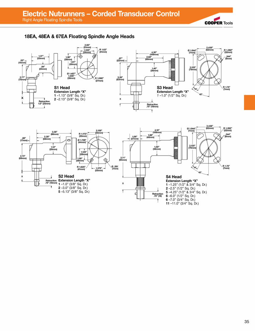
35
S3 Head Extension Length “X”1 –1.0” (1/2” Sq. Dr.)
S4 Head Extension Length “X”1 –1.25” (1/2” & 3/4” Sq. Dr.)2 –2.5” (1/2” Sq. Dr.)5 –4.25” (1/2” & 3/4” Sq. Dr.)6 –6.0” (1/2” Sq. Dr.)6 –7.0” (3/4” Sq. Dr.)11 –11.0” (3/4” Sq. Dr.)
18EA, 48EA & 67EA Floating Spindle Angle Heads
S1 Head Extension Length “X”1 –1.13” (3/8” Sq. Dr.)2 –2.13” (3/8” Sq. Dr.)
S2 Head Extension Length “X”1 –1.0” (3/8” Sq. Dr.)2 –3.0” (3/8” Sq. Dr.)5 –5.13” (3/8” Sq. Dr.)
Electric Nutrunners – Corded Transducer ControlRight Angle Floating Spindle Tools
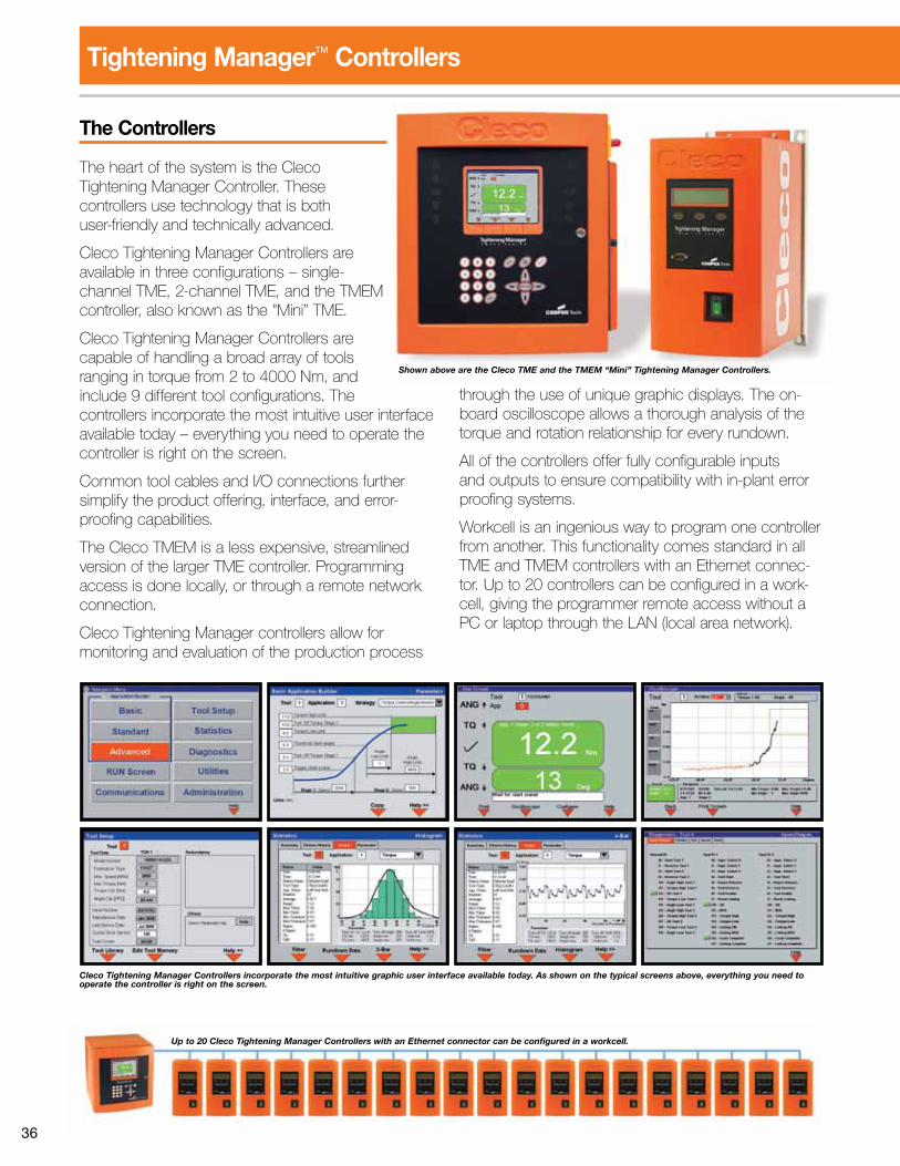
36
The Controllers
The heart of the system is the Cleco Tightening Manager Controller. These controllers use technology that is both user-friendly and technically advanced.
Cleco Tightening Manager Controllers are available in three configurations – single-channel TME, 2-channel TME, and the TMEM controller, also known as the "Mini” TME.
Cleco Tightening Manager Controllers are capable of handling a broad array of tools ranging in torque from 2 to 4000 Nm, and include 9 different tool configurations. The controllers incorporate the most intuitive user interface available today – everything you need to operate the controller is right on the screen.
Common tool cables and I/O connections further simplify the product offering, interface, and error-proofing capabilities.
The Cleco TMEM is a less expensive, streamlined version of the larger TME controller. Programming access is done locally, or through a remote network connection.
Cleco Tightening Manager controllers allow for monitoring and evaluation of the production process
through the use of unique graphic displays. The on-board oscilloscope allows a thorough analysis of the torque and rotation relationship for every rundown.
All of the controllers offer fully configurable inputs and outputs to ensure compatibility with in-plant error proofing systems.
Workcell is an ingenious way to program one controller from another. This functionality comes standard in all TME and TMEM controllers with an Ethernet connec-tor. Up to 20 controllers can be configured in a work-cell, giving the programmer remote access without a PC or laptop through the LAN (local area network).
Shown above are the Cleco TME and the TMEM “Mini” Tightening Manager Controllers.
Up to 20 Cleco Tightening Manager Controllers with an Ethernet connector can be configured in a workcell.
Cleco Tightening Manager Controllers incorporate the most intuitive graphic user interface available today. As shown on the typical screens above, everything you need to operate the controller is right on the screen.
Tightening Manager™ Controllers
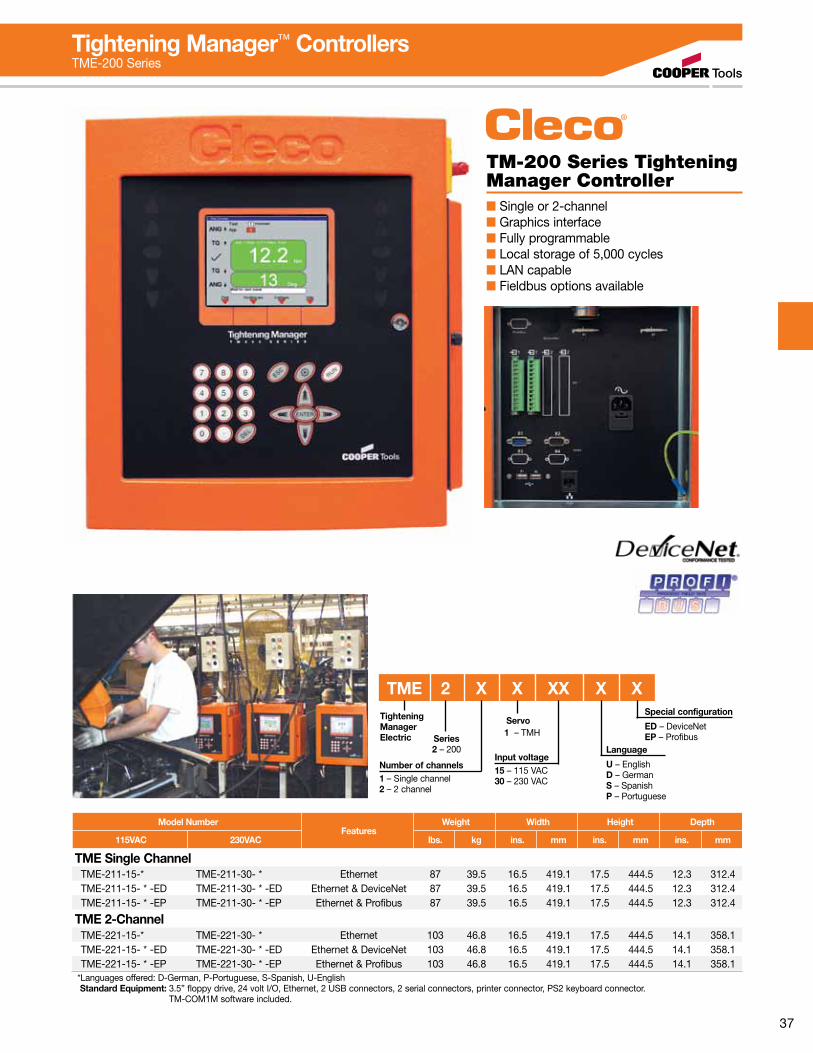
37
TM-200 Series Tightening Manager Controller■ Single or 2-channel■ Graphics interface■ Fully programmable■ Local storage of 5,000 cycles■ LAN capable■ Fieldbus options available
Input voltage15 – 115 VAC30 – 230 VAC
Language
U – EnglishD – GermanS – SpanishP – Portuguese
Tightening Manager Electric
Number of channels1 – Single channel2 – 2 channel
Series2 – 200
TME 2 X X XX X XSpecial configuration
ED – DeviceNetEP – Profibus
Servo 1 – TMH
Model NumberFeatures
Weight Width Height Depth
115VAC 230VAC lbs. kg ins. mm ins. mm ins. mm
TME Single ChannelTME-211-15-* TME-211-30- * Ethernet 87 39.5 16.5 419.1 17.5 444.5 12.3 312.4TME-211-15- * -ED TME-211-30- * -ED Ethernet & DeviceNet 87 39.5 16.5 419.1 17.5 444.5 12.3 312.4TME-211-15- * -EP TME-211-30- * -EP Ethernet & Profibus 87 39.5 16.5 419.1 17.5 444.5 12.3 312.4
TME 2-ChannelTME-221-15-* TME-221-30- * Ethernet 103 46.8 16.5 419.1 17.5 444.5 14.1 358.1TME-221-15- * -ED TME-221-30- * -ED Ethernet & DeviceNet 103 46.8 16.5 419.1 17.5 444.5 14.1 358.1TME-221-15- * -EP TME-221-30- * -EP Ethernet & Profibus 103 46.8 16.5 419.1 17.5 444.5 14.1 358.1
*Languages offered: D-German, P-Portuguese, S-Spanish, U-English Standard Equipment: 3.5” floppy drive, 24 volt I/O, Ethernet, 2 USB connectors, 2 serial connectors, printer connector, PS2 keyboard connector. TM-COM1M software included.
Tightening Manager™ ControllersTME-200 Series
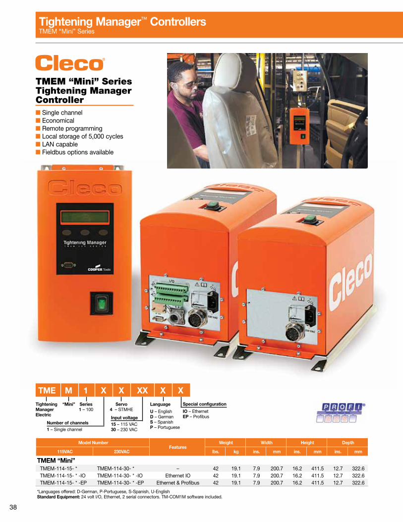
38
TMEM “Mini” Series Tightening Manager Controller■ Single channel■ Economical■ Remote programming■ Local storage of 5,000 cycles■ LAN capable■ Fieldbus options available
Model NumberFeatures
Weight Width Height Depth
115VAC 230VAC lbs. kg ins. mm ins. mm ins. mm
TMEM “Mini”TMEM-114-15- * TMEM-114-30- * – 42 19.1 7.9 200.7 16.2 411.5 12.7 322.6TMEM-114-15- * -IO TMEM-114-30- * -IO Ethernet IO 42 19.1 7.9 200.7 16.2 411.5 12.7 322.6TMEM-114-15- * -EP TMEM-114-30- * -EP Ethernet & Profibus 42 19.1 7.9 200.7 16.2 411.5 12.7 322.6
*Languages offered: D-German, P-Portuguese, S-Spanish, U-EnglishStandard Equipment: 24 volt I/O, Ethernet, 2 serial connectors. TM-COM1M software included.
Tightening Manager™ ControllersTMEM “Mini” Series
Input voltage15 – 115 VAC30 – 230 VAC
Language
U – EnglishD – GermanS – SpanishP – Portuguese
Tightening Manager Electric
Number of channels1 – Single channel
Series1 – 100
TME M 1 X X XX X XSpecial configuration
IO – EthernetEP – Profibus
Servo4 – STMHE
“Mini”

39
Tool CablesModel Number Swivel Length
Tool Extension Right Angle Inline Feet Meters
542778-1M* 542779-1M 544055-1M* 544056-1M* 3 1542778-2M* 542779-2M 544055-2M* 544056-2M* 6 2542778-3M 542779-3M 544055-3M 544056-3M 9 3542778-6M 542779-6M 544055-6M 544056-6M 19.5 6542778-8M 542779-8M 544055-8M 544056-8M 26 8542778-10M 542779-10M 544055-10M 544056-10M 33 10542778-15M 542779-15M 544055-15M 544056-15M 49 15
542779-20M 66 20542779-25M 82 25542779-30M 96 30542779-40M 131 40
542778-50M 542779-50M 544055-50M 544056-50M 164 50
Maximum cable length 100M 115VAC/20M 230VAC.Overall minimum cable length 3M.*Must be used with 542779 extension cable.
Swivel Cable
Swivel cable rotates 330° to absorb constant
twisting and turning.
Accessory Cables
Accessory Cable
Controller toInput
Accessory
Input Acc.to
Input Acc.
Controller toSynch Box
Controller to1 Spindle
Annunciator
Controller to2 Spindle
Annunciator
Synch Boxto Input
Accessory
Synch Box toAnnunciators
(2/more spindles)
Length
ft. m542985-3 542986-3 576058-3 542989-3 543451-3 542987-3 542988-3 3 1542985-9 542986-9 576058-9 542989-9 543451-9 542987-9 542988-9 9 3542985-25 542986-25 576058-25 542989-25 543451-25 542987-25 542988-25 25 7.5542985-50 542986-50 576058-50 542989-50 543451-50 542987-50 542988-50 50 15
Part No. Description Lengthft. m
543446-7 Ethernet crossover cable 7 2543490-10 Serial cable null modem 10 3
Direct Connect CablesConnects controller direct to PC
Phoenix ConnectorsPart No. Description
542892 Input Phoenix connector542893 Output Phoenix connector939348 Hood/strain TME I/O cable relief
8 Position Remote Parameter Switch
Description Part Number
Remote Parameter Switch 542979 (with 25’ integrated cable)Remote Parameter Switch 542979-50 (with 50’ integrated cable)
Tool & Cable TesterPart No. Description
961024 Tool & cable testertool memory programming
542991 Tool & cable tester
Special Adapter Cable
Part No. Description
542916-1 Adapter cable for Rotorresolver tools
Tightening Manager Upgrade KitsPart Number Description
543481 Upgrades a Standard TMEM to a TMEM I/O543334-EN Upgrades a Standard TME with a 6 character serial number to an Ethernet TME543334J-EN Upgrades a Standard TME with a serial number having a J as the seventh character to an Ethernet TME543335-ED Upgrades a Standard TME with a 6 character serial number to a DeviceNet TME543335J-ED Upgrades a Standard TME with a serial number having a J as the seventh character to a DeviceNet TME543941 Upgrades a Standard TME 200-U to -EP (Ethernet & Profibus TME)543942 Upgrades a Standard TME 200-U to -ED (Ethernet & DeviceNet TME)
Lever Extension KitsDescription Part No.
Lever Extension Kit (non-swivel) 541757Lever Extension Kit (swivel) 543414Note: Models for standard tool cable (non-swivel) and swivel cable.
Suspension BailDescription Part No.
Tool suspension bail 1110909
Electric Nutrunners & ControllersAccessories
Medium to Hard TorqueBelleville Washer Test Fixture is clamped in a vise and used to test tools (10 In. Lbs. – 100 Ft. Lbs., 1.13Nm – 135.6Nm). Washers can be rearranged to simulate “hard” or “soft” joints.
Test Fixture
536185
Part Number
3/4”100 Ft.Lbs.
Max. 1/2” Hex25 Ft.Lbs.
Max.
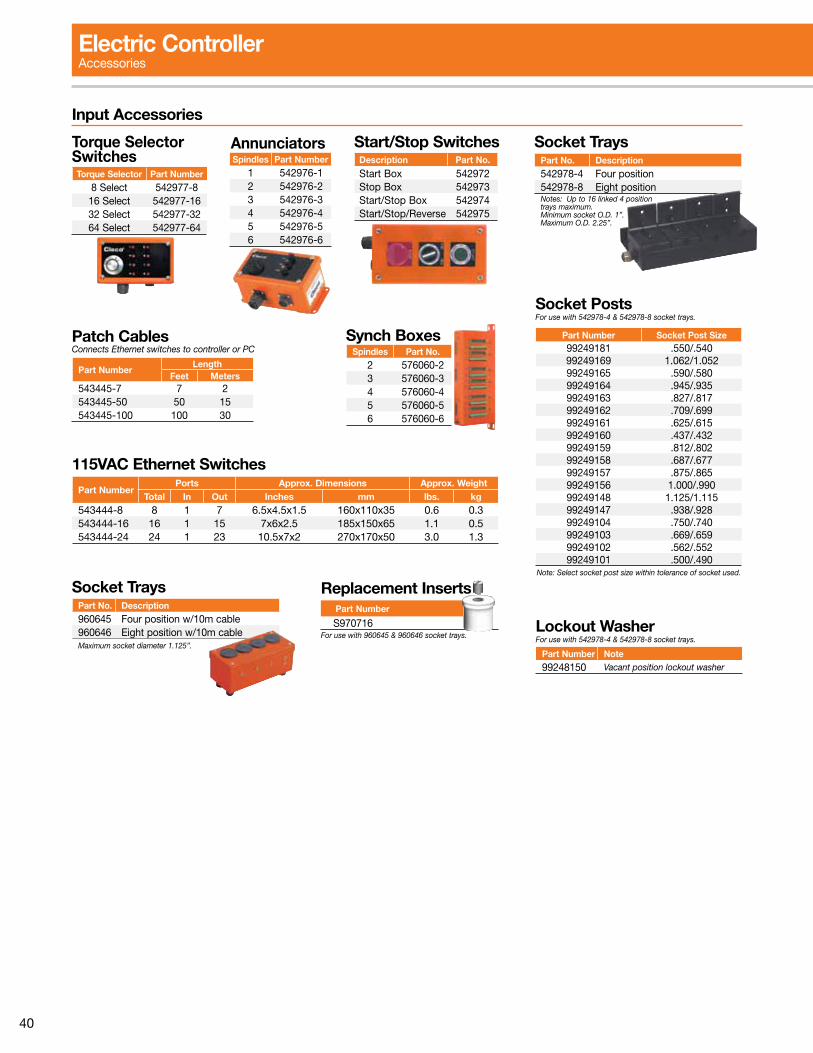
40
Input Accessories
Torque Selector SwitchesTorque Selector Part Number
8 Select 542977-816 Select 542977-1632 Select 542977-3264 Select 542977-64
AnnunciatorsSpindles Part Number
1 542976-12 542976-23 542976-34 542976-45 542976-56 542976-6
Start/Stop SwitchesDescription Part No.
Start Box 542972Stop Box 542973Start/Stop Box 542974Start/Stop/Reverse 542975
Patch CablesConnects Ethernet switches to controller or PC
Part NumberLength
Feet Meters543445-7 7 2543445-50 50 15543445-100 100 30
Synch BoxesSpindles Part No.
2 576060-23 576060-34 576060-45 576060-56 576060-6
115VAC Ethernet SwitchesPart Number
Ports Approx. Dimensions Approx. WeightTotal In Out Inches mm lbs. kg
543444-8 8 1 7 6.5x4.5x1.5 160x110x35 0.6 0.3543444-16 16 1 15 7x6x2.5 185x150x65 1.1 0.5543444-24 24 1 23 10.5x7x2 270x170x50 3.0 1.3
Socket TraysPart No. Description960645 Four position w/10m cable960646 Eight position w/10m cableMaximum socket diameter 1.125”.
For use with 960645 & 960646 socket trays.
Replacement Inserts
S970716 Part Number
Socket TraysPart No. Description542978-4 Four position542978-8 Eight positionNotes: Up to 16 linked 4 position trays maximum.Minimum socket O.D. 1”.Maximum O.D. 2.25”.
Socket PostsFor use with 542978-4 & 542978-8 socket trays.
Part Number Socket Post Size99249181 .550/.54099249169 1.062/1.05299249165 .590/.58099249164 .945/.93599249163 .827/.81799249162 .709/.69999249161 .625/.61599249160 .437/.43299249159 .812/.80299249158 .687/.67799249157 .875/.86599249156 1.000/.99099249148 1.125/1.11599249147 .938/.92899249104 .750/.74099249103 .669/.65999249102 .562/.55299249101 .500/.490
Note: Select socket post size within tolerance of socket used.
Lockout WasherFor use with 542978-4 & 542978-8 socket trays.
Part Number Note99248150 Vacant position lockout washer
Electric ControllerAccessories
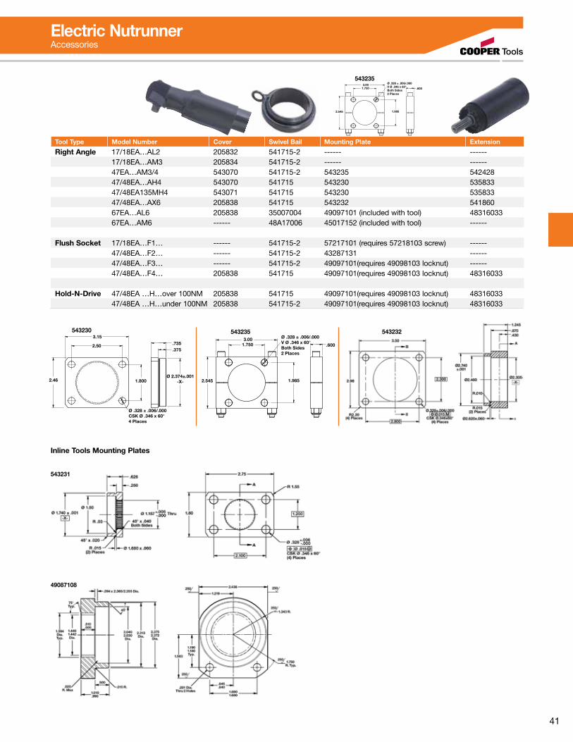
41
Ø .328 ± .006/.000CSK Ø .346 x 60°4 Places
Ø 2.374±.001-X-1.800
.375
3.15
2.50
2.46
.735
543230Ø .328 ± .006/.000V Ø .346 x 60°Both Sides2 Places
3.001.750 .600
1.9852.545
543235 543232
Ø .328 ± .006/.000V Ø .346 x 60°Both Sides2 Places
3.001.750 .600
1.9852.545
543235
Tool Type Model Number Cover Swivel Bail Mounting Plate Extension
Right Angle 17/18EA…AL2 205832 541715-2 ------ ------17/18EA…AM3 205834 541715-2 ------ ------47EA…AM3/4 543070 541715-2 543235 54242847/48EA…AH4 543070 541715 543230 53583347/48EA135MH4 543071 541715 543230 53583347/48EA…AX6 205838 541715 543232 54186067EA…AL6 205838 35007004 49097101 (included with tool) 4831603367EA…AM6 ------ 48A17006 45017152 (included with tool) ------
Flush Socket 17/18EA…F1… ------ 541715-2 57217101 (requires 57218103 screw) ------47/48EA…F2… ------ 541715-2 43287131 ------47/48EA…F3… ------ 541715-2 49097101(requires 49098103 locknut) ------47/48EA…F4… 205838 541715 49097101(requires 49098103 locknut) 48316033
Hold-N-Drive 47/48EA …H…over 100NM 205838 541715 49097101(requires 49098103 locknut) 4831603347/48EA …H…under 100NM 205838 541715-2 49097101(requires 49098103 locknut) 48316033
Electric NutrunnerAccessories
543231
49087108
Inline Tools Mounting Plates

42
Durability. Speed. Ergonomics.Cost Effective Solution for Quality Critical Applications.Cleco CurrentControl electric assembly tools provide an up-sell solution to quality critical applications presently specifying a pneumatic clutch tool and verifier combination. Cleco proprietary CurrentControl systems up-sell on superior productivity, error proofing and process flexibility.
Our Cleco controller systems are recognized globally for “best in class” software interface. This is accomplished through simple navigation, basic programming screens, visual programming graphics and real-time process feedback. Our latest innovation “Auto Program” takes the guesswork out of programming. Simply enter the applica-tion torque target and the software automatically compiles the program for production use.
Adjustable angle head
allows flexible
orientation
New Cleco TMEI Controller
Unrestricted Speed Control
Electric Nutrunners – Corded Current Control
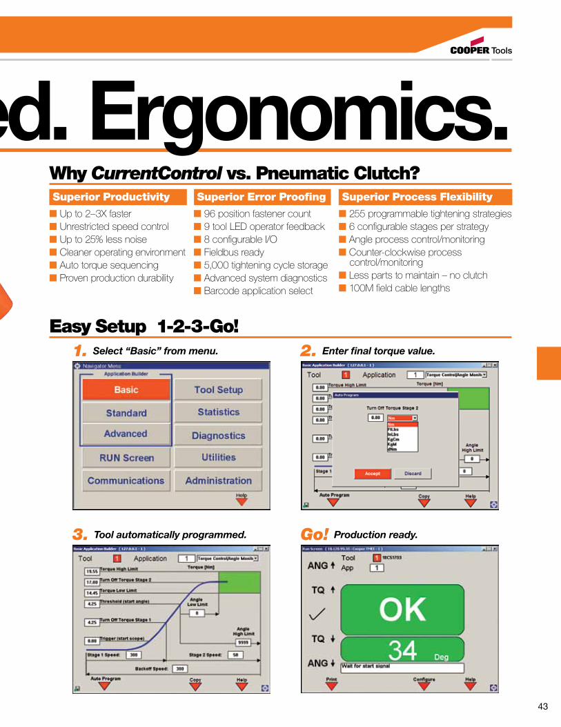
43
Durability. Speed. Ergonomics.Why CurrentControl vs. Pneumatic Clutch? Superior Productivity
■ Up to 2–3X faster■ Unrestricted speed control■ Up to 25% less noise■ Cleaner operating environment■ Auto torque sequencing■ Proven production durability
Superior Process Flexibility
■ 255 programmable tightening strategies■ 6 configurable stages per strategy■ Angle process control/monitoring■ Counter-clockwise process control/monitoring■ Less parts to maintain – no clutch■ 100M field cable lengths
Superior Error Proofing
■ 96 position fastener count■ 9 tool LED operator feedback■ 8 configurable I/O■ Fieldbus ready■ 5,000 tightening cycle storage■ Advanced system diagnostics■ Barcode application select
Easy Setup 1-2-3-Go!1. Select “Basic” from menu. 2. Enter final torque value.
3. Tool automatically programmed. Go! Production ready.
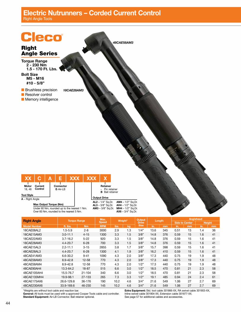
44
18CAE28AM3
48CAE58AM3
Right Angle SeriesTorque Range 2 - 230 Nm 1.5 - 170 Ft. Lbs.Bolt Size M5 - M16 #10 - 5/8”
■ Brushless precision■ Resolver control■ Memory intelligence
Right Angle Torque Range Max.Speed Weight* Output
DriveSize
LengthAnglehead
Side to Center HeightModel Number ft. lbs. Nm RPM lbs. kg in. mm in. mm in. mm
18CAE08AL2 1.5-5.9 2-8 3000 2.9 1.3 1/4” 13.6 345 0.51 13 1.4 3618CAE15AM3 3.0-11.1 4-15 1300 3.3 1.5 3/8” 14.8 376 0.59 15 1.6 4118CAE22AM3 3.7-16.2 5-22 920 3.3 1.5 3/8” 14.8 376 0.59 15 1.6 4118CAE28AM3 4.4-20.7 6-28 700 3.3 1.5 3/8” 14.8 376 0.59 15 1.6 4148CAE15AL3 2.2-11.1 3-15 2855 3.8 1.7 3/8” 15.7 398 0.59 15 1.6 4148CAE28AL3 4.4-20.7 6-28 1300 4.1 1.9 3/8” 16.2 410 0.59 15 1.6 4148CAE41AM3 6.6-30.2 9-41 1090 4.3 2.0 3/8” 17.3 440 0.75 19 1.9 4848CAE58AM3 8.9-42.8 12-58 770 4.3 2.0 3/8” 17.3 440 0.75 19 1.9 4848CAE58AM4 8.9-42.8 12-58 770 4.3 2.0 1/2” 17.3 440 0.75 19 1.9 4848CAE90AH4 13.3-64.2 18-87 515 6.6 3.0 1/2” 18.5 470 0.81 21 2.3 5848CAE105AH4 15.5-76.7 21-104 340 6.6 3.0 1/2” 18.5 470 0.81 21 2.3 5848CAE135MH4 19.9-98.1 27-133 265 7.3 3.3 1/2” 19.1 485 0.94 24 2.4 6148CAE175AX6 26.6-129.8 36-176 190 10.2 4.6 3/4” 21.6 549 1.06 27 2.7 6948CAE230AX6 33.9-169.6 46-230 145 10.2 4.6 3/4” 21.6 549 1.06 27 2.7 69
*Weights are without tool cable and reaction bar. General: All tools must be used with a approved Cooper Tools cable and controller.Standard Equipment: Air-LB Connector. Ball retainer optional.
Extra Equipment: Std. tool cable 301866-XX, RA swivel cable 301903-XX, Inline swivel cable 301904-XX, Extension cable 301877-XX.See page 57 for additional cables and accessories.
Electric Nutrunners – Corded Current ControlRight Angle Tools
Tool StyleA – Right Angle
Current Control
XX C A E XXX XXX XRetainer- Pin retainer B Ball retainer
Output Drive
AL2 – 1/4” Sq.Dr. AM4 – 1/2” Sq.Dr.AL3 – 3/8” Sq.Dr. AH4 – 1/2” Sq.Dr.AM3 – 3/8” Sq.Dr. MH4 – 1/2” Sq.Dr. AX6 – 3/4” Sq.Dr.
ConnectorE-Air-LB
Motor18, 48
Max Output Torque (Nm)Under 60 Nm, rounded up to the nearest 1 Nm.Over 60 Nm, rounded to the nearest 5 Nm.
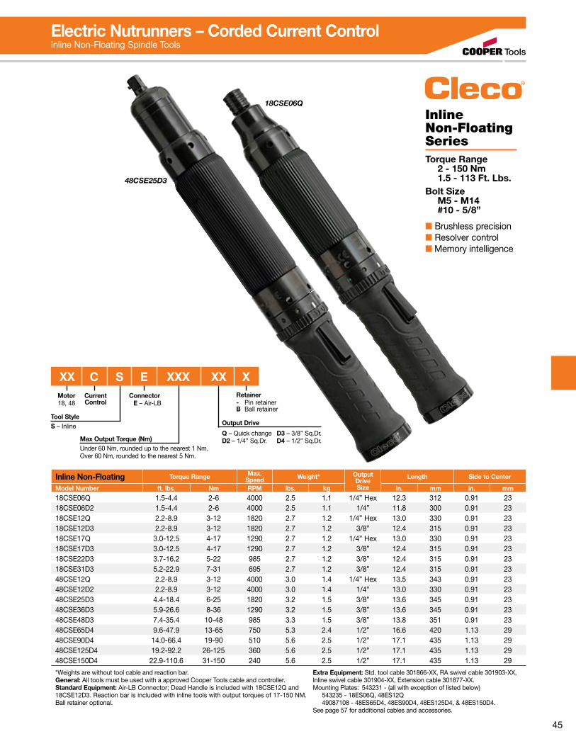
45
18CSE06Q
48CSE25D3
Inline Non-Floating SeriesTorque Range 2 - 150 Nm 1.5 - 113 Ft. Lbs.Bolt Size M5 - M14 #10 - 5/8”
■ Brushless precision■ Resolver control■ Memory intelligence
Inline Non-Floating Torque Range Max.Speed Weight* Output
DriveSize
Length Side to Center
Model Number ft. lbs. Nm RPM lbs. kg in. mm in. mm
18CSE06Q 1.5-4.4 2-6 4000 2.5 1.1 1/4” Hex 12.3 312 0.91 2318CSE06D2 1.5-4.4 2-6 4000 2.5 1.1 1/4” 11.8 300 0.91 2318CSE12Q 2.2-8.9 3-12 1820 2.7 1.2 1/4” Hex 13.0 330 0.91 2318CSE12D3 2.2-8.9 3-12 1820 2.7 1.2 3/8” 12.4 315 0.91 2318CSE17Q 3.0-12.5 4-17 1290 2.7 1.2 1/4” Hex 13.0 330 0.91 2318CSE17D3 3.0-12.5 4-17 1290 2.7 1.2 3/8” 12.4 315 0.91 2318CSE22D3 3.7-16.2 5-22 985 2.7 1.2 3/8” 12.4 315 0.91 2318CSE31D3 5.2-22.9 7-31 695 2.7 1.2 3/8” 12.4 315 0.91 2348CSE12Q 2.2-8.9 3-12 4000 3.0 1.4 1/4” Hex 13.5 343 0.91 2348CSE12D2 2.2-8.9 3-12 4000 3.0 1.4 1/4” 13.0 330 0.91 2348CSE25D3 4.4-18.4 6-25 1820 3.2 1.5 3/8” 13.6 345 0.91 2348CSE36D3 5.9-26.6 8-36 1290 3.2 1.5 3/8” 13.6 345 0.91 2348CSE48D3 7.4-35.4 10-48 985 3.3 1.5 3/8” 13.8 351 0.91 2348CSE65D4 9.6-47.9 13-65 750 5.3 2.4 1/2” 16.6 420 1.13 2948CSE90D4 14.0-66.4 19-90 510 5.6 2.5 1/2” 17.1 435 1.13 2948CSE125D4 19.2-92.2 26-125 360 5.6 2.5 1/2” 17.1 435 1.13 2948CSE150D4 22.9-110.6 31-150 240 5.6 2.5 1/2” 17.1 435 1.13 29
*Weights are without tool cable and reaction bar. General: All tools must be used with a approved Cooper Tools cable and controller.Standard Equipment: Air-LB Connector; Dead Handle is included with 18CSE12Q and 18CSE12D3. Reaction bar is included with inline tools with output torques of 17-150 NM. Ball retainer optional.
Extra Equipment: Std. tool cable 301866-XX, RA swivel cable 301903-XX, Inline swivel cable 301904-XX, Extension cable 301877-XX.Mounting Plates: 543231 - (all with exception of listed below) 543235 - 18ES06Q, 48ES12Q 49087108 - 48ES65D4, 48ES90D4, 48ES125D4, & 48ES150D4.See page 57 for additional cables and accessories.
Electric Nutrunners – Corded Current ControlInline Non-Floating Spindle Tools
Motor18, 48
Tool StyleS – Inline
Current Control
XX C S E XXX XX XRetainer- Pin retainer B Ball retainer
Output Drive
Q – Quick change D3 – 3/8” Sq.Dr.D2 – 1/4” Sq.Dr. D4 – 1/2” Sq.Dr.
Connector E – Air-LB
Max Output Torque (Nm)Under 60 Nm, rounded up to the nearest 1 Nm.Over 60 Nm, rounded to the nearest 5 Nm.

46
Pistol Grip SeriesTorque Range 2 - 150 Nm 1.5 - 113 Ft. Lbs.Bolt Size M5 - M14 #10 - 5/8”
■ Brushless precision■ Resolver control■ Memory intelligence
Pistol Grip Torque Range Max.Speed Weight* Output
DriveSize
Length Side to Center
Model Number ft. lbs. Nm RPM lbs. kg in. mm in. mm
18CPE06Q 1.5-4.4 2-6 4000 2.2 1.0 1/4” Hex 7.0 178 0.84 2118CPE06D2 1.5-4.4 2-6 4000 2.2 1.0 1/4” 6.5 165 0.84 2118CPE12Q 2.2-8.9 3-12 1820 2.4 1.1 1/4” Hex 7.7 196 0.84 2118CPE12D3 2.2-8.9 3-12 1820 2.4 1.1 3/8” 7.2 183 0.84 2118CPE17Q 3.0-12.5 4-17 1290 2.4 1.1 1/4” Hex 7.7 196 0.84 2118CPE17D3 3.0-12.5 4-17 1290 2.4 1.1 3/8” 7.2 183 0.84 2118CPE22D3 3.7-16.2 5-22 985 2.4 1.1 3/8” 7.2 183 0.84 2118CPE31D3 5.2-22.9 7-31 695 2.4 1.1 3/8” 7.2 183 0.84 2148CPE12Q 2.2-8.9 3-12 4000 2.7 1.2 1/4” Hex 8.3 211 0.84 2148CPE12D2 2.2-8.9 3-12 4000 2.7 1.2 1/4” 7.7 196 0.84 2148CPE25D3 4.4-18.4 6-25 1820 2.9 1.3 3/8” 8.4 213 0.84 2148CPE36D3 5.9-26.6 8-36 1290 2.9 1.3 3/8” 8.4 213 0.84 2148CPE48D3 7.4-35.4 10-48 985 3.0 1.4 3/8” 8.6 218 0.84 2148CPE65D4 9.6-47.9 13-65 750 5.0 2.3 1/2” 10.8 274 1.1 2848CPE90D4 14.0-66.4 19-90 510 5.3 2.4 1/2” 11.3 287 1.1 2848CPE125D4 19.2-92.2 26-125 360 5.3 2.4 1/2” 11.3 287 1.1 2848CPE150D4 22.9-110.6 31-150 240 5.3 2.4 1/2” 11.3 287 0.9 23
*Weights are without tool cable and reaction bar. General: All tools must be used with a approved Cooper Tools cable and controller.Standard Equipment: Air-LB Connector; Suspension Bail; Dead Handle is included with 18CPE12Q & 18CPE12D3. Reaction bar is included with pistol tools with output torques of 17-150 Nm. Ball retainer optional.
Extra Equipment: Std. tool cable 301866-XX, RA swivel cable 301903-XX, Inline swivel cable 301904-XX, Extension cable 301877-XX.See page 57 for additional cables and accessories.
18CPE6Q
48CPE25D3
Electric Nutrunners – Corded Current ControlPistol Grip Tools
Tool StyleP – Pistol
Current Control
XX C P E XXX XX XRetainer- Pin retainer B Ball retainer
Output Drive
Q – Quick change D3 – 3/8” Sq.Dr.D2 – 1/4” Sq.Dr. D4 – 1/2” Sq.Dr.
ConnectorE-Air-LB
Motor18, 48
Max Output Torque (Nm)Under 60 Nm, rounded up to the nearest 1 Nm.Over 60 Nm, rounded to the nearest 5 Nm.

47
Push-to-Start SeriesTorque Range 2 - 12 Nm 1.5 - 8.9 Ft. Lbs.Bolt Size M5 - M6 #10 - 1/4”
■ Brushless precision■ Resolver control■ Memory intelligence
Push-to-Start Torque Range Max.Speed Weight* Output
DriveSize
Length Side to Center
Model Number ft. lbs. Nm RPM lbs. kg in. mm in. mm
18CPE06QP 1.5-4.4 2-6 4000 2.66 1.19 1/4” Hex 9.35 238 0.84 2118CPE06D3P 2.2-8.9 3-12 4000 2.66 1.19 3/8” 8.8 224 0.84 2118CPE12QP 2.2-8.9 3-12 1820 2.83 1.27 1/4” Hex 9.35 196 0.84 2118CPE12D3P 2.2-8.9 3-12 1820 2.83 1.27 3/8” 8.8 224 0.84 2118CSE06QP 1.5-4.4 2-6 4000 2.93 1.31 1/4” Hex 14.75 375 0.91 2318CSE06D3P 2.2-8.9 3-12 4000 2.93 1.31 3/8” 14.20 360 0.91 2318CSE12QP 2.2-8.9 3-12 1820 3.10 1.40 1/4” Hex 14.75 375 0.91 2318CSE12D3P 2.2-8.9 3-12 1820 3.10 1.40 3/8” 14.20 360 0.91 23
*Weights are without tool cable and reaction bar. General: All tools must be used with a approved Cooper Tools cable and controller.Standard Equipment: Air-LB Connector; Suspension Bail on pistol models; Dead Handle (301857) is included with 18CPE12Q & 18CPE12D3.
Extra Equipment: Std. tool cable 301866-XX, RA swivel cable 301903-XX, Inline swivel cable 301904-XX, Extension cable 301877-XX.See page 57 for additional cables and accessories.
18CPE06QP
18CSE06QP
Electric Nutrunners – Corded Current ControlPush-to-Start Pistol Grip/Inline Tools
Tool StyleP – PistolS – Inline
Current Control
XX C X E XXX XX PPush-to-Start
Output Drive
Q – Quick changeD3 – 3/8” Sq.Dr.
ConnectorE-Air-LB
Motor18, 48
Max Output Torque (Nm)Under 60 Nm, rounded up to the nearest 1 Nm.

48
Inline Floating Spindle SeriesTorque Range 2 - 248 Nm 1.5 - 182.9 Ft. Lbs.Bolt Size M5 - M16 #10 - 5/8”
■ Brushless precision■ Resolver control■ Memory intelligence
Inline Floating Spindle Torque Range Max.
Speed Weight* OutputDriveSize
Length Side to Center
Model Number ft. lbs. Nm RPM lbs. kg in. mm in. mm
18CSE06ZA 1.5-4.4 2-6 4000 3.0 1.4 1/4 15.5 394 0.91 2318CSE12ZA 2.2-8.9 3-12 1820 3.2 1.5 1/4 16.0 406 0.91 2318CSE17ZA 3.0-12.5 4-17 1290 3.2 1.5 1/4 16.0 406 0.91 23 48CSE12ZA 2.2-8.9 3-12 4000 3.4 1.5 1/4 16.7 425 0.91 2348CSE271ZB 5.9-19.9 8-27 1820 5.8 2.6 3/8 22.0 559 0.92 2348CSE361ZB 5.2-26.6 7-36 1290 5.8 2.6 3/8 22.0 559 0.92 23 48CSE602ZB 8.1-42.0 11-57 855 8.4 3.8 1/2 24.4 620 1.10 2848CSE702ZB 10.3-50.2 14-68 570 8.4 3.8 1/2 24.4 620 1.10 2848CSE802ZB 12.5-60.5 17-82 450 9.6 4.4 1/2 26.7 678 1.10 3148CSE1152ZB 18.4-84.8 25-115 320 9.6 4.4 1/2 26.7 678 1.10 3148CSE1502ZB 22.9-110.6 31-150 245 9.6 4.4 1/2 26.7 678 1.10 3148CSE1653ZB 24.3-121.7 33-165 220 14.6 6.6 3/4 28.6 726 1.57 4048CSE2503ZB 36.8-182.9 50-248 145 14.6 6.6 3/4 28.6 726 1.57 40
*Weights are without tool cable or reaction bar if so equipped. General: All tools must be used with a approved Cooper Tools cable and controller.Standard Equipment: Air-LB Connector.Tools have thru hole output.
Extra Equipment: Std. tool cable 301866-XX, RA swivel cable 301903-XX, Inline swivel cable 301904-XX, Extension cable 301877-XX.See page 57 for additional cables and accessories.
1.22”58.87mm
2.318”
1.159”29.43mm
.669”16.99mm
1.339”34.01mm
3.15”80.01mm
31.1mm
1ZBZA 2ZB 3ZB
Dimensional Spindle Float: 1” (25mm) ZA 2” (50mm) 1ZB, 2ZB, 3ZB
tolerances = ± .004” (0.1mm)
0.25”6.3mm
1.22”31.1mm 1.31”
33.3mm1.73”
44.0mm
0.35”9.0mm
1.37”34.9mm
1.41”35.92mm
1.41”35.92mm
2.00”50.8mm
1.97”50.04mm
.56”14.22mm
1.50”38.1mm
1.10”27.94mm
M5 x 0.8Thd. Typ.
Base Plate Mounting Dimensions
18CSE12ZA
Electric Nutrunners – Corded Current ControlInline Floating Spindle Tools
Tool StyleS – Inline
Current Control
XX C S E XXX XXXOutput Drive
ZA – 1/4” Sq.Dr.1ZB – 3/8” Sq.Dr.2ZB – 1/2” Sq.Dr.3ZB – 3/4” Sq.Dr.
ConnectorE-Air-LB
Motor18, 48
Max Output Torque (Nm)Under 60 Nm, rounded up to the nearest 1 Nm.Over 60 Nm, rounded to the nearest 5 Nm.
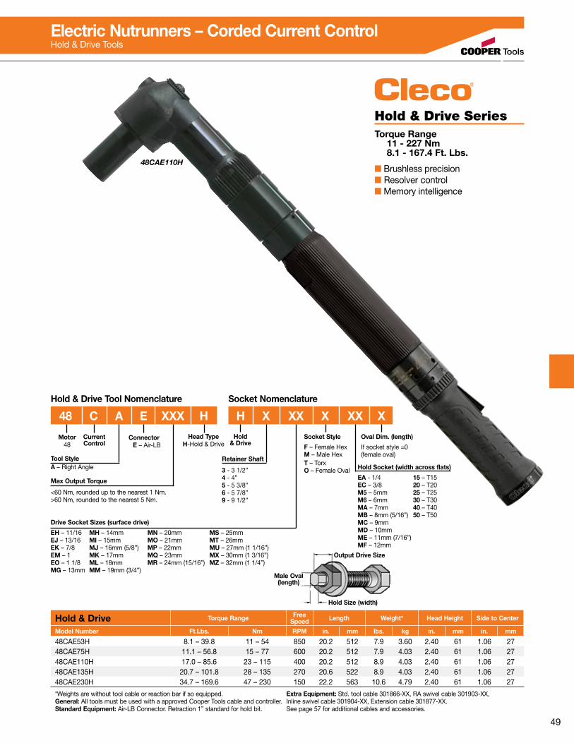
49
48CAE110H
Hold & Drive Torque Range FreeSpeed Length Weight* Head Height Side to Center
Model Number Ft.Lbs. Nm RPM in. mm lbs. kg in. mm in. mm
48CAE53H 8.1 – 39.8 11 – 54 850 20.2 512 7.9 3.60 2.40 61 1.06 2748CAE75H 11.1 – 56.8 15 – 77 600 20.2 512 7.9 4.03 2.40 61 1.06 2748CAE110H 17.0 – 85.6 23 – 115 400 20.2 512 8.9 4.03 2.40 61 1.06 2748CAE135H 20.7 – 101.8 28 – 135 270 20.6 522 8.9 4.03 2.40 61 1.06 2748CAE230H 34.7 – 169.6 47 – 230 150 22.2 563 10.6 4.79 2.40 61 1.06 27
*Weights are without tool cable or reaction bar if so equipped. General: All tools must be used with a approved Cooper Tools cable and controller.Standard Equipment: Air-LB Connector. Retraction 1” standard for hold bit.
Extra Equipment: Std. tool cable 301866-XX, RA swivel cable 301903-XX, Inline swivel cable 301904-XX, Extension cable 301877-XX.See page 57 for additional cables and accessories.
Hold & Drive SeriesTorque Range 11 - 227 Nm 8.1 - 167.4 Ft. Lbs.
■ Brushless precision■ Resolver control■ Memory intelligence
Electric Nutrunners – Corded Current ControlHold & Drive Tools
H X XX X XX XHold & Drive Tool Nomenclature Socket Nomenclature
48 C A E XXX H
Max Output Torque
<60 Nm, rounded up to the nearest 1 Nm. >60 Nm, rounded to the nearest 5 Nm.
Retainer Shaft
3 - 3 1/2”4 - 4”5 - 5 3/8”6 - 5 7/8”9 - 9 1/2”
Motor48
Current Control
Socket Style
F – Female HexM – Male HexT – TorxO – Female Oval
Oval Dim. (length)
If socket style =0 (female oval)
Connector E – Air-LB
Tool StyleA – Right Angle
Hold & Drive
Head TypeH-Hold & Drive
Drive Socket Sizes (surface drive)
EH – 11/16 MH – 14mm MN – 20mm MS – 25mmEJ – 13/16 MI – 15mm MO – 21mm MT – 26mmEK – 7/8 MJ – 16mm (5/8”) MP – 22mm MU – 27mm (1 1/16”)EM – 1 MK – 17mm MQ – 23mm MX – 30mm (1 3/16”)EO – 1 1/8 ML – 18mm MR – 24mm (15/16”) MZ – 32mm (1 1/4”)MG – 13mm MM – 19mm (3/4”)
Hold Socket (width across flats)
EA - 1/4 15 – T15EC – 3/8 20 – T20M5 – 5mm 25 – T25M6 – 6mm 30 – T30MA – 7mm 40 – T40MB – 8mm (5/16”) 50 – T50MC – 9mm MD – 10mm ME – 11mm (7/16”) MF – 12mm
Male Oval (length)
Hold Size (width)
Output Drive Size

50
Flush Socket SeriesTorque Range Bolt Size 4.9 - 234 Nm M8 - M21 3.6 - 172.6 Ft. Lbs. 1/2” - 1 3/16”
■ Brushless precision■ Resolver control■ Memory intelligence
Flush Socket HeadType
Torque Range FreeSpeed Weight* Length
Anglehead
Side to Center Height
Model Number ft. lbs. Nm RPM lbs. kg in. mm in. mm in. mm
18CAE16F F1 3.6-11.8 4.9-16 1225 4.4 2.00 16.0 406 0.55 14 1.54 3918CAE23F F1 3.4-17.0 4.6-23 860 4.4 2.00 16.0 406 0.55 14 1.54 3918CAE30F F1 4.4-22.1 6.0-30 655 4.4 2.00 16.0 406 0.55 14 1.54 3948CAE37F F2 5.9-27.3 8.0-37 1225 5.4 2.43 18.7 474 0.67 17 1.69 4348CAE52F F2 8.1-38.3 11-52 860 5.4 2.43 18.7 474 0.67 17 1.69 4348CAE53F F3 8.1-39.0 11-53 850 6.0 2.74 20.0 509 0.87 22 2.32 5948CAE75F F3 11.1-55.3 15-75 600 6.0 2.74 20.0 509 0.87 22 2.32 5948CAE110F F3 17.0-81.1 23-110 400 7.4 3.38 20.5 521 0.87 22 2.32 5948CAE135F F4 19.9-99.5 27-135 270 8.9 4.03 20.6 522 1.06 27 2.40 6148CAE230F F4 34.7-172.6 47-230 150 10.6 4.79 22.2 563 1.06 27 2.40 61
*Weights are without tool cable or reaction bar if so equipped. General: All tools must be used with a approved Cooper Tools cable and controller.Standard Equipment: Air-LB Connector.
Extra Equipment: Std. tool cable 301866-XX, RA swivel cable 301903-XX, Inline swivel cable 301904-XX, Extension cable 301877-XX.See page 57 for additional cables and accessories.
18CAE30F1
Electric Nutrunners – Corded Current ControlFlush Socket Tools
FX XX X X
Max Output Torque
F1 16,23, 30 Nm F3 53, 75, 110 NmF2 37, 52 Nm F4 135, 230 Nm<60 Nm, rounded up to the nearest 1 Nm. >60 Nm, rounded to the nearest 5 Nm.
Head Type
F1 Head 8–15mm socket capacityF2 Head 10–15mm socket capacityF3 Head 13–21mm socket capacityF4 Head 13–21mm socket capacity
Motor18, 48
Tool StyleA – Right Angle
Current Control
Flush Socket
Output Type0–Standard 1–Fast Lead 2–Magnetic
Extension Length
0 – Flush 4 – 1/2” 8 – 1”2 – 1/4” 6 – 3/4”
Flush Socket Tool Nomenclature Socket Nomenclature
XX C A E XXX FConnectorE – Air-LB
Socket Size
EC – 3/8 MB – 8mm (5/16”) MJ – 16mm (5/8”)ED – 7/16 MD – 10mm MK – 17mmEE – 1/2 ME – 11mm (7/16”) ML – 18mmEF – 9/16 MF – 12mm MM – 19mm (3/4”)EH – 11/16 MG – 13mm MN – 20mmEJ – 13/16 MH – 14mm MO – 21mm MI – 15mm
X Dimension For Flush SocketHead in. mm Socket Size Range
F1 1.54 39 8–15mmF2 1.69 43 10–15mmF3 2.32 59 13–21mmF4 2.4 61 17–21mm
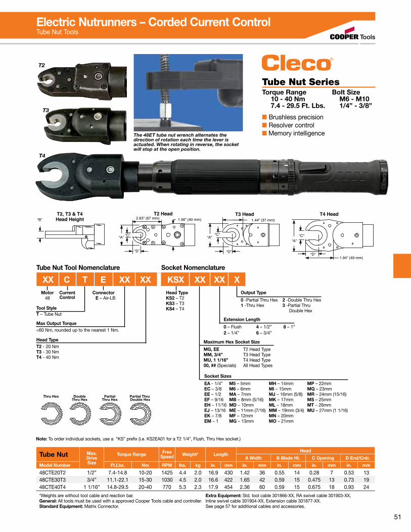
51
T2
T3
T4
“B”T2, T3 & T4Head Height
“A”
2.63” (67 mm) 1.56” (40 mm)T2 Head T3 Head
1.44” (37 mm)
“A”“C”
“D”
T4 Head
1.94” (49 mm)
“A”“C”
“D”
“C”
“D”
Tube Nut Max.DriveSize
Torque Range FreeSpeed Weight* Length
Head
A Width B Blade Ht. C Opening D End/Cntr.
Model Number Ft.Lbs. Nm RPM lbs. kg in. mm in. mm in. mm in. mm in. mm
48CTE20T2 1/2” 7.4-14.8 10-20 1425 4.4 2.0 16.9 430 1.42 36 0.55 14 0.28 7 0.53 1348CTE30T3 3/4” 11.1-22.1 15-30 1030 4.5 2.0 16.6 422 1.65 42 0.59 15 0.475 13 0.73 1948CTE40T4 1 1/16” 14.8-29.5 20-40 770 5.3 2.3 17.9 454 2.36 60 0.59 15 0.675 18 0.93 24
*Weights are without tool cable and reaction bar. General: All tools must be used with a approved Cooper Tools cable and controller.Standard Equipment: Matrix Connector.
Extra Equipment: Std. tool cable 301866-XX, RA swivel cable 301903-XX, Inline swivel cable 301904-XX, Extension cable 301877-XX.See page 57 for additional cables and accessories.
Tube Nut SeriesTorque Range Bolt Size 10 - 40 Nm M6 - M10 7.4 - 29.5 Ft. Lbs. 1/4” - 3/8”
■ Brushless precision■ Resolver control■ Memory intelligenceThe 48ET tube nut wrench alternates the
direction of rotation each time the lever is actuated. When rotating in reverse, the socket will stop at the open position.
Note: To order individual sockets, use a “KS” prefix (i.e. KS2EA01 for a T2 1/4”, Flush, Thru Hex socket.)
Electric Nutrunners – Corded Current ControlTube Nut Tools
Tube Nut Tool Nomenclature Socket Nomenclature
Max Output Torque<60 Nm, rounded up to the nearest 1 Nm.
Head TypeT2 - 20 NmT3 - 30 NmT4 - 40 Nm
Motor48
Tool StyleT – Tube Nut
Current Control
Output Type
0 -Partial Thru Hex 2 -Double Thru Hex1 -Thru Hex 3 -Partial Thru Double Hex
Extension Length
0 – Flush 4 – 1/2” 8 – 1”2 – 1/4” 6 – 3/4”
Maximum Hex Socket Size
MG, EE T2 Head TypeMM, 3/4” T3 Head TypeMU, 1 1/16” T4 Head Type00, ## (Specials) All Head Types
Thru Hex DoubleThru Hex
PartialThru Hex
Partial Thru Double Hex
Connector E – Air-LB
Head TypeKS2 – T2KS3 – T3KS4 – T4
XX C T E XX XX KSX XX XX X
Socket Sizes
EA - 1/4” M5 – 5mm MH – 14mm MP – 22mmEC – 3/8 M6 – 6mm MI – 15mm MQ – 23mmEE – 1/2 MA – 7mm MJ – 16mm (5/8) MR – 24mm (15/16)EF – 9/16 MB – 8mm (5/16) MK – 17mm MS – 25mmEH – 11/16 MD – 10mm ML – 18mm MT – 26mmEJ – 13/16 ME – 11mm (7/16) MM – 19mm (3/4) MU – 27mm (1 1/16)EK – 7/8 MF – 12mm MN – 20mmEM – 1 MG – 13mm MO – 21mm
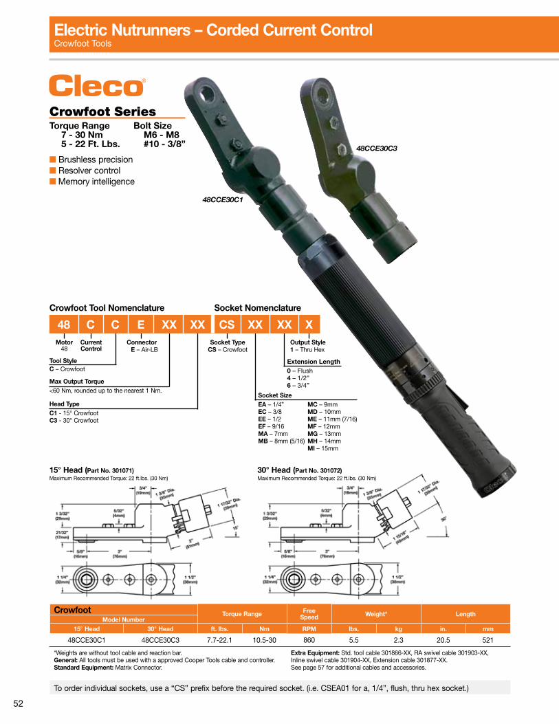
52
48CCE30C3
Crowfoot Torque Range FreeSpeed Weight* Length
Model Number15° Head 30° Head ft. lbs. Nm RPM lbs. kg in. mm
48CCE30C1 48CCE30C3 7.7-22.1 10.5-30 860 5.5 2.3 20.5 521
*Weights are without tool cable and reaction bar. General: All tools must be used with a approved Cooper Tools cable and controller.Standard Equipment: Matrix Connector.
Extra Equipment: Std. tool cable 301866-XX, RA swivel cable 301903-XX, Inline swivel cable 301904-XX, Extension cable 301877-XX.See page 57 for additional cables and accessories.
To order individual sockets, use a “CS” prefix before the required socket. (i.e. CSEA01 for a, 1/4”, flush, thru hex socket.)
Crowfoot SeriesTorque Range Bolt Size 7 - 30 Nm M6 - M8 5 - 22 Ft. Lbs. #10 - 3/8”
■ Brushless precision■ Resolver control■ Memory intelligence
48CCE30C1
15° Head (Part No. 301071)Maximum Recommended Torque: 22 ft.lbs. (30 Nm)
30° Head (Part No. 301072)Maximum Recommended Torque: 22 ft.lbs. (30 Nm)
Electric Nutrunners – Corded Current ControlCrowfoot Tools
Max Output Torque<60 Nm, rounded up to the nearest 1 Nm.
Head TypeC1 - 15° CrowfootC3 - 30° Crowfoot
Motor48
Tool StyleC – Crowfoot
Current Control
Socket SizeEA – 1/4” MC – 9mmEC – 3/8 MD – 10mmEE – 1/2 ME – 11mm (7/16)EF – 9/16 MF – 12mmMA – 7mm MG – 13mmMB – 8mm (5/16) MH – 14mm MI – 15mm
Socket NomenclatureCrowfoot Tool Nomenclature
Output Style1 – Thru Hex
Connector E – Air-LB
Socket TypeCS – Crowfoot
Extension Length0 – Flush4 – 1/2”6 – 3/4”
48 C C E XX XX CS XX XX X

53
Notes
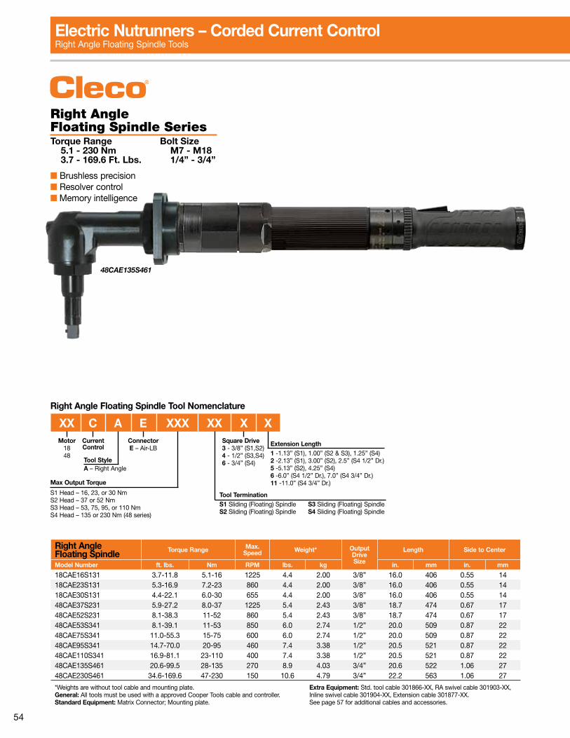
54
Right Angle Floating Spindle SeriesTorque Range Bolt Size 5.1 - 230 Nm M7 - M18 3.7 - 169.6 Ft. Lbs. 1/4” - 3/4”
■ Brushless precision■ Resolver control■ Memory intelligence
Right Angle Floating Spindle Torque Range Max.
Speed Weight* OutputDriveSize
Length Side to Center
Model Number ft. lbs. Nm RPM lbs. kg in. mm in. mm
18CAE16S131 3.7-11.8 5.1-16 1225 4.4 2.00 3/8” 16.0 406 0.55 1418CAE23S131 5.3-16.9 7.2-23 860 4.4 2.00 3/8” 16.0 406 0.55 1418CAE30S131 4.4-22.1 6.0-30 655 4.4 2.00 3/8” 16.0 406 0.55 1448CAE37S231 5.9-27.2 8.0-37 1225 5.4 2.43 3/8” 18.7 474 0.67 1748CAE52S231 8.1-38.3 11-52 860 5.4 2.43 3/8” 18.7 474 0.67 1748CAE53S341 8.1-39.1 11-53 850 6.0 2.74 1/2” 20.0 509 0.87 2248CAE75S341 11.0-55.3 15-75 600 6.0 2.74 1/2” 20.0 509 0.87 2248CAE95S341 14.7-70.0 20-95 460 7.4 3.38 1/2” 20.5 521 0.87 2248CAE110S341 16.9-81.1 23-110 400 7.4 3.38 1/2” 20.5 521 0.87 2248CAE135S461 20.6-99.5 28-135 270 8.9 4.03 3/4” 20.6 522 1.06 2748CAE230S461 34.6-169.6 47-230 150 10.6 4.79 3/4” 22.2 563 1.06 27
*Weights are without tool cable and mounting plate. General: All tools must be used with a approved Cooper Tools cable and controller.Standard Equipment: Matrix Connector; Mounting plate.
Extra Equipment: Std. tool cable 301866-XX, RA swivel cable 301903-XX, Inline swivel cable 301904-XX, Extension cable 301877-XX.See page 57 for additional cables and accessories.
48CAE135S461
Max Output Torque
S1 Head – 16, 23, or 30 NmS2 Head – 37 or 52 NmS3 Head – 53, 75, 95, or 110 NmS4 Head – 135 or 230 Nm (48 series)
Tool TerminationS1 Sliding (Floating) Spindle S3 Sliding (Floating) SpindleS2 Sliding (Floating) Spindle S4 Sliding (Floating) Spindle
Motor1848
Tool StyleA – Right Angle
Current Control
XX C A E XXX XX X X
Right Angle Floating Spindle Tool Nomenclature
ConnectorE – Air-LB
Square Drive3 - 3/8” (S1,S2)4 - 1/2” (S3,S4)6 - 3/4” (S4)
Extension Length1 -1.13” (S1), 1.00” (S2 & S3), 1.25” (S4)2 -2.13” (S1), 3.00” (S2), 2.5” (S4 1/2” Dr.)5 -5.13” (S2), 4.25” (S4)6 -6.0” (S4 1/2” Dr.), 7.0” (S4 3/4” Dr.)11 -11.0” (S4 3/4” Dr.)
Electric Nutrunners – Corded Current ControlRight Angle Floating Spindle Tools
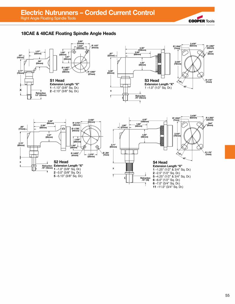
55
S3 Head Extension Length “X”1 –1.0” (1/2” Sq. Dr.)
S4 Head Extension Length “X”1 –1.25” (1/2” & 3/4” Sq. Dr.)2 –2.5” (1/2” Sq. Dr.)5 –4.25” (1/2” & 3/4” Sq. Dr.)6 –6.0” (1/2” Sq. Dr.)6 –7.0” (3/4” Sq. Dr.)11 –11.0” (3/4” Sq. Dr.)
18CAE & 48CAE Floating Spindle Angle Heads
S1 Head Extension Length “X”1 –1.13” (3/8” Sq. Dr.)2 –2.13” (3/8” Sq. Dr.)
S2 Head Extension Length “X”1 –1.0” (3/8” Sq. Dr.)2 –3.0” (3/8” Sq. Dr.)5 –5.13” (3/8” Sq. Dr.)
Electric Nutrunners – Corded Current ControlRight Angle Floating Spindle Tools
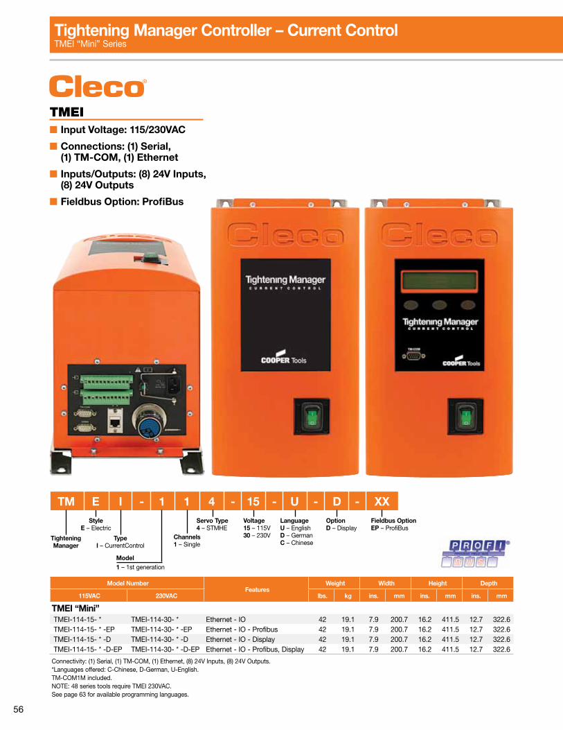
56
TMEI■ Input Voltage: 115/230VAC
■ Connections: (1) Serial, (1) TM-COM, (1) Ethernet
■ Inputs/Outputs: (8) 24V Inputs, (8) 24V Outputs
■ Fieldbus Option: ProfiBus
Tightening Manager Controller – Current ControlTMEI “Mini” Series
TypeI – CurrentControl
StyleE – Electric
Voltage15 – 115V30 – 230V
TM E I - 1 1 4 - 15 - U - D - XX
Model1 – 1st generation
Channels1 – Single
Servo Type4 – STMHE
LanguageU – EnglishD – GermanC – Chinese
OptionD – Display
Fieldbus OptionEP – ProfiBus
Tightening Manager
Model NumberFeatures
Weight Width Height Depth
115VAC 230VAC lbs. kg ins. mm ins. mm ins. mm
TMEI “Mini” TMEI-114-15- * TMEI-114-30- * Ethernet - IO 42 19.1 7.9 200.7 16.2 411.5 12.7 322.6 TMEI-114-15- * -EP TMEI-114-30- * -EP Ethernet - IO - Profibus 42 19.1 7.9 200.7 16.2 411.5 12.7 322.6 TMEI-114-15- * -D TMEI-114-30- * -D Ethernet - IO - Display 42 19.1 7.9 200.7 16.2 411.5 12.7 322.6 TMEI-114-15- * -D-EP TMEI-114-30- * -D-EP Ethernet - IO - Profibus, Display 42 19.1 7.9 200.7 16.2 411.5 12.7 322.6
Connectivity: (1) Serial, (1) TM-COM, (1) Ethernet, (8) 24V Inputs, (8) 24V Outputs. *Languages offered: C-Chinese, D-German, U-English. TM-COM1M included.NOTE: 48 series tools require TMEI 230VAC.See page 63 for available programming languages.
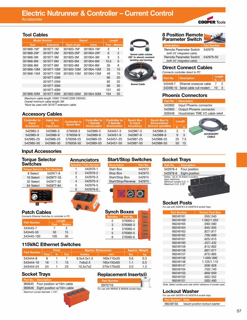
57
Tool CablesModel Number Swivel Length
Tool Extension Right Angle Inline Feet Meters
301866-1M* 301877-1M 301903-1M* 301904-1M* 3 1301866-2M* 301877-2M 301903-2M* 301904-2M* 6 2301866-3M 301877-3M 301903-3M 301904-3M 9 3301866-6M 301877-6M 301903-6M 301904-6M 19.5 6301866-8M 301877-8M 301903-8M 301904-8M 26 8301866-10M 301877-10M 301903-10M 301904-10M 33 10301866-15M 301877-15M 301903-15M 301904-15M 49 15
301877-20M 66 20301877-25M 82 25301877-30M 96 30301877-40M 131 40
301866-50M 301877-50M 301903-50M 301904-50M 164 50Maximum cable length 100M 115VAC/20M 230VAC.Overall minimum cable length 3M.*Must be used with 301877 extension cable.
Swivel Cable
Swivel cable rotates 330° to absorb constant
twisting and turning.
8 Position Remote Parameter Switch
Description Part Number
Remote Parameter Switch 542979 (with 25’ integrated cable)Remote Parameter Switch 542979-50 (with 50’ integrated cable)
Accessory Cables
ACCESSORY CABLE
Controller toInput
Accessory
Input Acc.to
Input Acc.
Controller toSynch Box
Controller to1 Spindle
Annunciator
Controller to2 Spindle
Annunciator
Synch Boxto Input
Accessory
Synch Box toAnnunciators
(2/more spindles)
Length
ft. m542985-3 542986-3 576058-3 542989-3 543451-3 542987-3 542988-3 3 1542985-9 542986-9 576058-9 542989-9 543451-9 542987-9 542988-9 9 3542985-25 542986-25 576058-25 542989-25 543451-25 542987-25 542988-25 25 7.5542985-50 542986-50 576058-50 542989-50 543451-50 542987-50 542988-50 50 15
Input Accessories
Torque Selector SwitchesTorque Selector Part Number
8 Select 542977-816 Select 542977-1632 Select 542977-3264 Select 542977-64
AnnunciatorsSpindles Part Number
1 542976-12 542976-23 542976-34 542976-45 542976-56 542976-6
Start/Stop SwitchesDescription Part No.
Start Box 542972Stop Box 542973Start/Stop Box 542974Start/Stop/Reverse 542975
Patch CablesConnects Ethernet Switches to controller or PC
Part NumberLength
Feet Meters543445-7 7 2543445-50 50 15543445-100 100 30
Synch BoxesSpindles Part No.
2 576060-23 576060-34 576060-45 576060-56 576060-6
115VAC Ethernet SwitchesPart Number
Ports Approx. Dimensions Approx. WeightTotal In Out Inches mm lbs. kg
543444-8 8 1 7 6.5x4.5x1.5 160x110x35 0.6 0.3543444-16 16 1 15 7x6x2.5 185x150x65 1.1 0.5543444-24 24 1 23 10.5x7x2 270x170x50 3.0 1.3
Socket TraysPart No. Description960645 Four position w/10m cable960646 Eight position w/10m cableMaximum socket diameter 1.125”.
For use with 960645 & 960646 socket trays.
Replacement Inserts
S970716 Part Number
Socket TraysPart No. Description542978-4 Four position542978-8 Eight positionNotes: Up to 16 linked 4 position trays maximum.Minimum socket O.D. 1”.Maximum O.D. 2.25”.
Socket PostsFor use with 542978-4 & 542978-8 socket trays.
Part Number Socket Post Size99249181 .550/.54099249169 1.062/1.05299249165 .590/.58099249164 .945/.93599249163 .827/.81799249162 .709/.69999249161 .625/.61599249160 .437/.43299249159 .812/.80299249158 .687/.67799249157 .875/.86599249156 1.000/.99099249148 1.125/1.11599249147 .938/.92899249104 .750/.74099249103 .669/.65999249102 .562/.55299249101 .500/.490
Note: Select socket post size within tolerance of socket used.
Lockout WasherFor use with 542978-4 & 542978-8 socket trays.
Part Number Note99248150 Vacant position lockout washer
Part No. Description Lengthft. m
543446-7 Ethernet crossover cable 7 2543490-10 Serial cable null modem 10 3
Direct Connect CablesConnects controller direct to PC
Phoenix ConnectorsPart No. Description
542892 Input Phoenix connector542893 Output Phoenix connector939348 Hood/strain TME I/O cable relief
Electric Nutrunner & Controller – Current ControlAccessories
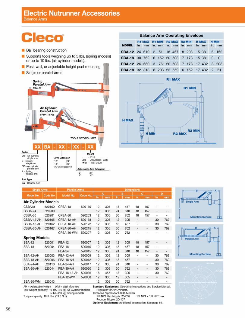
58
■ Ball bearing construction
■ Supports tools weighing up to 5 lbs. (spring models) or up to 10 lbs. (air cylinder models).
■ Post, wall, or adjustable height post mounting
■ Single or parallel arms
R1 MAX
R1 MIN
R2 MINH MIN
H MAX
R2 MAX
Balance Arm Operating Envelope
MODEL R1 MAX R1 MIN R2 MAX R2 MIN H MAX H MIN
in. mm in. mm in. mm in. mm in. mm in. mm
SBA-12 24 610 2 51 18 457 8 203 15 381 6 152
SBA-18 30 762 6 152 20 508 7 178 15 381 0 0
PBA-12 26 660 3 76 20 508 7 178 17 432 8 203
PBA-18 32 813 8 203 22 559 6 152 17 432 2 51
Single Arms Parallel Arms Dimensions
Model No. Code No. Model No. Code No.A B C D
in. mm in. mm in. mm in. mm
Air Cylinder ModelsCSBA18 520160 CPBA-18 520170 12 305 18 457 18 457 - -CSBA-24 520200 12 305 24 610 18 457 - -CSBA-30 520201 CPBA-30 520203 12 305 30 762 18 457 - -CSBA-12-AH 520165 CPBA-12-AH 520178 12 305 12 305 - - 30 762CSBA-18-AH 520162 CPBA-18-AH 520172 12 305 18 457 - - 30 762CSBA-30-AH 520167 CPBA-30-AH 520215 12 305 30 762 - - 30 762
CPBA-30-WM 520207 12 305 30 762 - - - -
Spring ModelsSBA-12 520001 PBA-12 520007 12 305 12 305 18 457 - -SBA-18 520004 PBA-18 520010 12 305 18 457 18 457 - -
PBA-24 520045 12 305 24 610 18 457 - -SBA-12-AH 520003 PBA-12-AH 520009 12 305 12 305 - - 30 762SBA-18-AH 520006 PBA-18-AH 520012 12 305 18 457 - - 30 762SBA-24-AH 520110 PBA-24-AH 520047 12 305 24 610 - - 30 762SBA-30-AH 520044 PBA-30-AH 520050 12 305 30 762 - - 30 762
PBA-18-18-AH 520036 18 457 18 305 - - 30 762PBA-12-WM 520008 12 305 12 305 - - - -
SBA-30-WM 520043 12 305 30 762 - - - -
AH = Adjustable Height WM = Wall MountedTool weight capacity: 10 lbs. (4.6 kg) Air Cylinder models 5 lbs. (2.3 kg) Spring modelsTorque capacity: 10 ft. lbs. (13.5 Nm)
Standard Equipment: Operating Instructions and Service Manual. Regulator for Air Cylinders.
Threaded Nipples for CSBA Models 1/4 NPT Hex Nipple: 204032 1/4 NPT x 1/8 NPT Hex Reducer Nipple: 204137
Optional Equipment: Additional accessories: See page 59.
TOOLS NOT INCLUDED
Air CylinderParallel Arm CPBA-18-AH
SpringParallel Arm PBA-18
Mount- – PostAH – Adjustable HeightWM – Wall Mount
Series
CS – Air cylinder, single armS – Spring, single armCP – Air cylinder, parallel armP – Spring, parallel arm
Tool Type
BA – Balance Arm
XX BA - XX - XX - XX
Arm Extension12” 24”18” 30”(12” unless specified)
Adjustable Arm Extension
12” 24”18” 30”
Electric Nutrunner AccessoriesBalance Arms
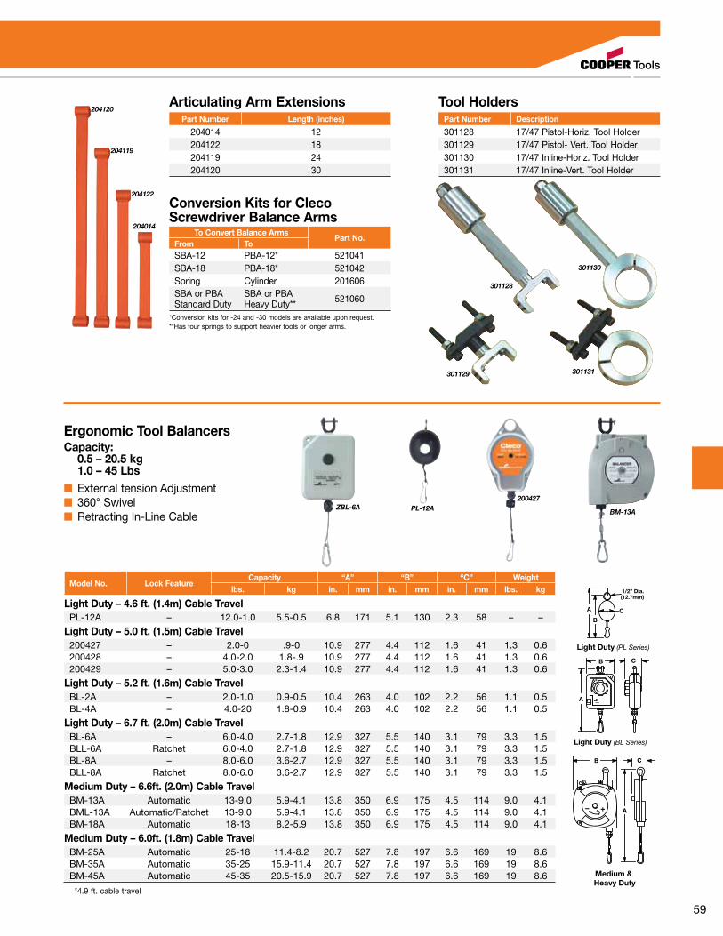
59
BM-13AZBL-6A
200427PL-12A
Ergonomic Tool BalancersCapacity: 0.5 – 20.5 kg 1.0 – 45 Lbs■ External tension Adjustment■ 360° Swivel■ Retracting In-Line Cable
Model No. Lock FeatureCapacity “A” “B” “C” Weight
lbs. kg in. mm in. mm in. mm lbs. kg
Light Duty – 4.6 ft. (1.4m) Cable TravelPL-12A – 12.0-1.0 5.5-0.5 6.8 171 5.1 130 2.3 58 – –
Light Duty – 5.0 ft. (1.5m) Cable Travel200427 – 2.0-0 .9-0 10.9 277 4.4 112 1.6 41 1.3 0.6200428 – 4.0-2.0 1.8-.9 10.9 277 4.4 112 1.6 41 1.3 0.6200429 – 5.0-3.0 2.3-1.4 10.9 277 4.4 112 1.6 41 1.3 0.6
Light Duty – 5.2 ft. (1.6m) Cable TravelBL-2A – 2.0-1.0 0.9-0.5 10.4 263 4.0 102 2.2 56 1.1 0.5BL-4A – 4.0-20 1.8-0.9 10.4 263 4.0 102 2.2 56 1.1 0.5
Light Duty – 6.7 ft. (2.0m) Cable TravelBL-6A – 6.0-4.0 2.7-1.8 12.9 327 5.5 140 3.1 79 3.3 1.5BLL-6A Ratchet 6.0-4.0 2.7-1.8 12.9 327 5.5 140 3.1 79 3.3 1.5BL-8A – 8.0-6.0 3.6-2.7 12.9 327 5.5 140 3.1 79 3.3 1.5BLL-8A Ratchet 8.0-6.0 3.6-2.7 12.9 327 5.5 140 3.1 79 3.3 1.5
Medium Duty – 6.6ft. (2.0m) Cable TravelBM-13A Automatic 13-9.0 5.9-4.1 13.8 350 6.9 175 4.5 114 9.0 4.1BML-13A Automatic/Ratchet 13-9.0 5.9-4.1 13.8 350 6.9 175 4.5 114 9.0 4.1BM-18A Automatic 18-13 8.2-5.9 13.8 350 6.9 175 4.5 114 9.0 4.1
Medium Duty – 6.0ft. (1.8m) Cable TravelBM-25A Automatic 25-18 11.4-8.2 20.7 527 7.8 197 6.6 169 19 8.6BM-35A Automatic 35-25 15.9-11.4 20.7 527 7.8 197 6.6 169 19 8.6BM-45A Automatic 45-35 20.5-15.9 20.7 527 7.8 197 6.6 169 19 8.6
*4.9 ft. cable travel
B
A
C
+
_
+– A
B C
1/2” Dia.(12.7mm)
C
B
A
Light Duty (PL Series)
Light Duty (BL Series)Medium & Heavy Duty
B
A
C
+
_
+– A
B C
1/2” Dia.(12.7mm)
C
B
A
Light Duty (PL Series)
Light Duty (BL Series)Medium & Heavy Duty
204120
204119
204122
204014
Conversion Kits for Cleco Screwdriver Balance Arms
To Convert Balance ArmsPart No.
From ToSBA-12 PBA-12* 521041SBA-18 PBA-18* 521042Spring Cylinder 201606SBA or PBAStandard Duty
SBA or PBAHeavy Duty** 521060
*Conversion kits for -24 and -30 models are available upon request.**Has four springs to support heavier tools or longer arms.
Articulating Arm ExtensionsPart Number Length (inches)
204014 12204122 18204119 24204120 30
301129
301128
301130
301131
Tool HoldersPart Number Description
301128 17/47 Pistol-Horiz. Tool Holder301129 17/47 Pistol- Vert. Tool Holder301130 17/47 Inline-Horiz. Tool Holder301131 17/47 Inline-Vert. Tool Holder
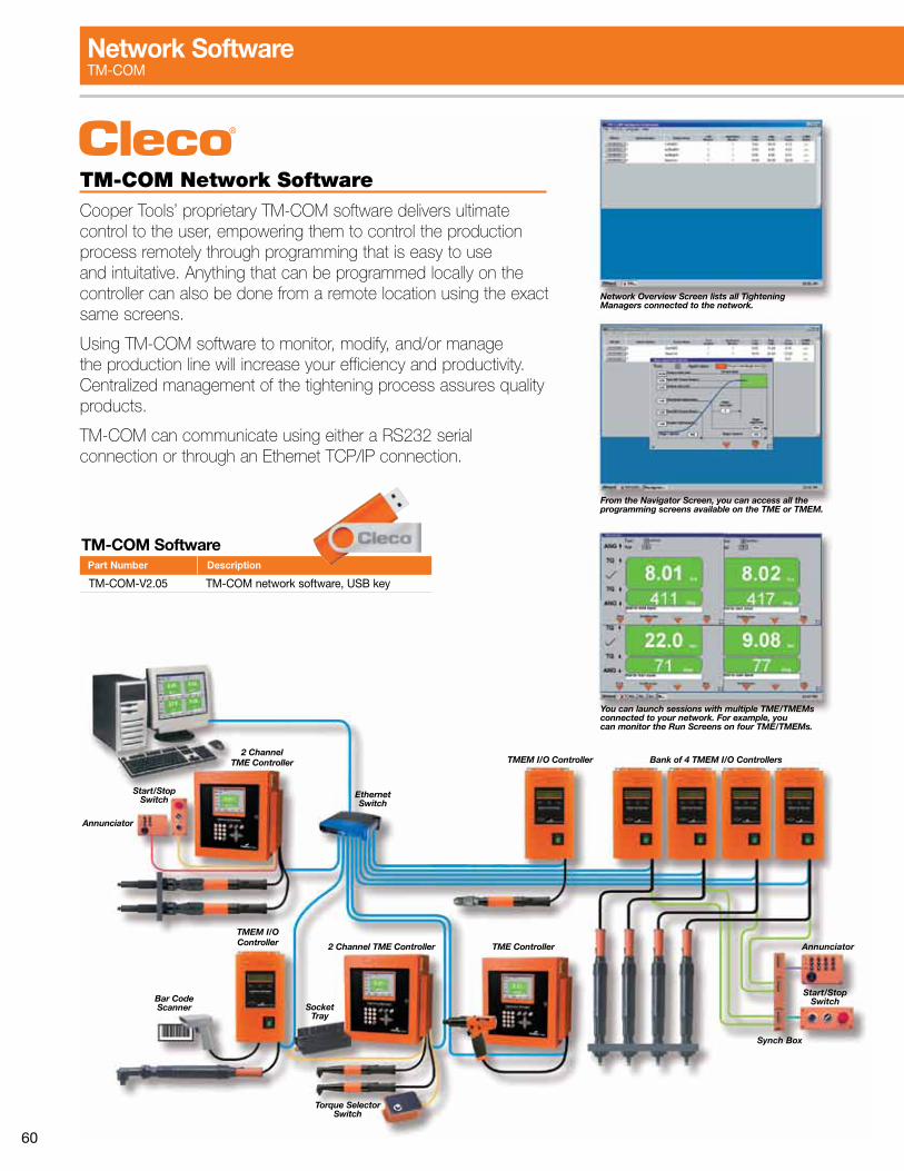
60
Start/Stop Switch Ethernet
Switch
Annunciator
Annunciator
Start/Stop Switch
Synch Box
2 Channel TME Controller TMEM I/O Controller Bank of 4 TMEM I/O Controllers
TMEM I/O Controller TME Controller2 Channel TME Controller
Bar Code Scanner Socket
Tray
Torque Selector Switch
Network Overview Screen lists all Tightening Managers connected to the network.
From the Navigator Screen, you can access all the programming screens available on the TME or TMEM.
You can launch sessions with multiple TME/TMEMs connected to your network. For example, you can monitor the Run Screens on four TME/TMEMs.
TM-COM Network SoftwareCooper Tools’ proprietary TM-COM software delivers ultimate control to the user, empowering them to control the production process remotely through programming that is easy to use and intuitative. Anything that can be programmed locally on the controller can also be done from a remote location using the exact same screens.
Using TM-COM software to monitor, modify, and/or manage the production line will increase your efficiency and productivity. Centralized management of the tightening process assures quality products.
TM-COM can communicate using either a RS232 serial connection or through an Ethernet TCP/IP connection.
TM-COM Software
TM-COM-V2.05 TM-COM network software, USB key
Part Number Description
Network SoftwareTM-COM
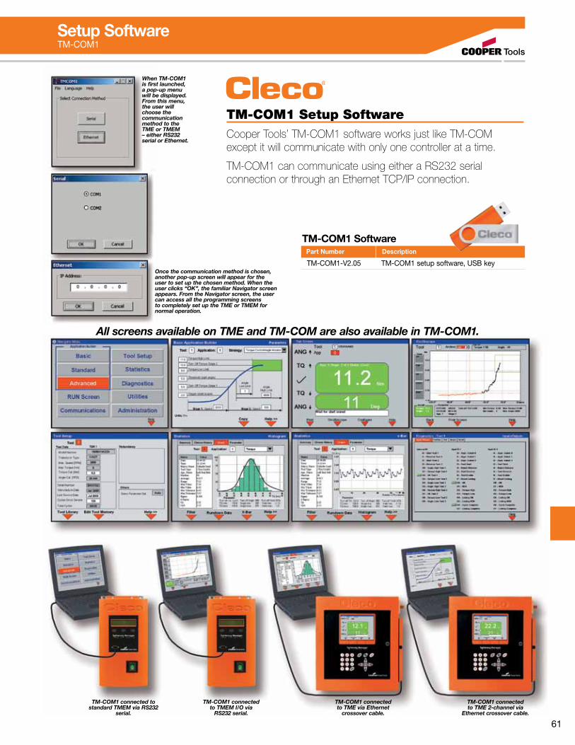
61
TM-COM1 Setup SoftwareCooper Tools’ TM-COM1 software works just like TM-COM except it will communicate with only one controller at a time.
TM-COM1 can communicate using either a RS232 serial connection or through an Ethernet TCP/IP connection.
Setup SoftwareTM-COM1
All screens available on TME and TM-COM are also available in TM-COM1.
TM-COM1 connected to standard TMEM via RS232
serial.
TM-COM1 connected to TMEM I/O via
RS232 serial.
TM-COM1 connected to TME via Ethernet
crossover cable.
TM-COM1 connected to TME 2-channel via
Ethernet crossover cable.
When TM-COM1 is first launched, a pop-up menu will be displayed. From this menu, the user will choose the communication method to the TME or TMEM – either RS232 serial or Ethernet.
Once the communication method is chosen, another pop-up screen will appear for the user to set up the chosen method. When the user clicks “OK”, the familiar Navigator screen appears. From the Navigator screen, the user can access all the programming screens to completely set up the TME or TMEM for normal operation.
TM-COM1 Software
TM-COM1-V2.05 TM-COM1 setup software, USB key
Part Number Description
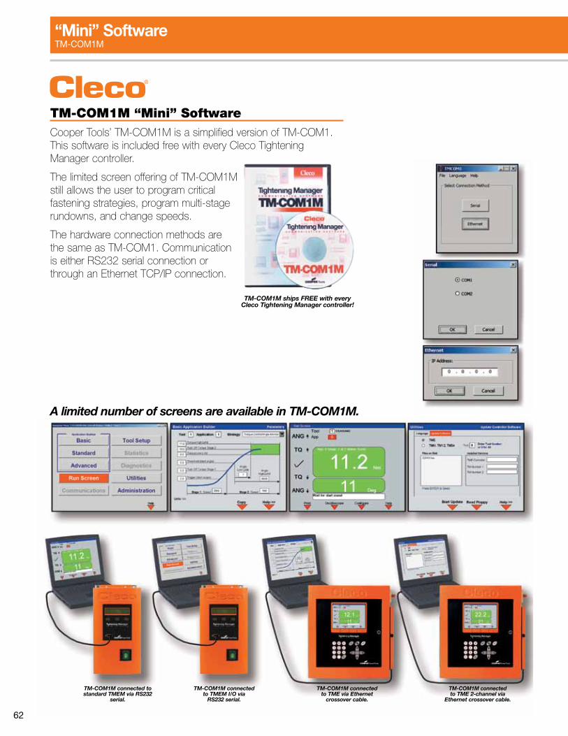
62
TM-COM1M “Mini” SoftwareCooper Tools’ TM-COM1M is a simplified version of TM-COM1. This software is included free with every Cleco Tightening Manager controller.
The limited screen offering of TM-COM1M still allows the user to program critical fastening strategies, program multi-stage rundowns, and change speeds.
The hardware connection methods are the same as TM-COM1. Communication is either RS232 serial connection or through an Ethernet TCP/IP connection.
TM-COM1M ships FREE with every Cleco Tightening Manager controller!
TM-COM1M connected to standard TMEM via RS232
serial.
TM-COM1M connected to TMEM I/O via
RS232 serial.
TM-COM1M connected to TME via Ethernet
crossover cable.
TM-COM1M connected to TME 2-channel via
Ethernet crossover cable.
A limited number of screens are available in TM-COM1M.
“Mini” SoftwareTM-COM1M
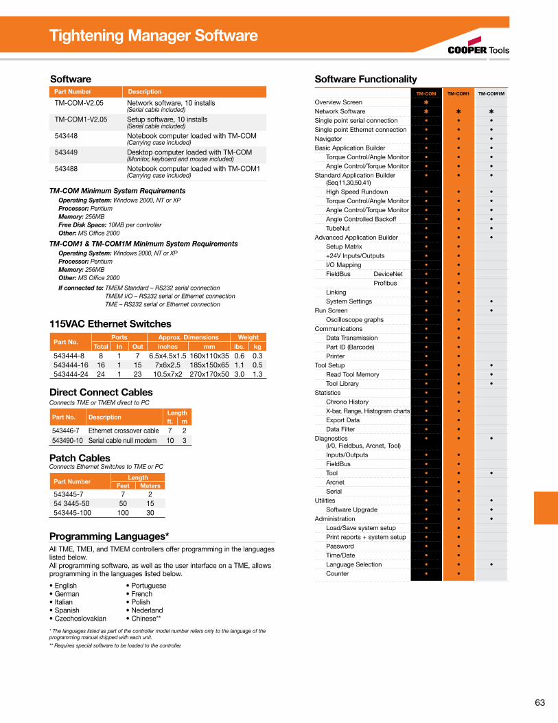
63
Software
TM-COM-V2.05 Network software, 10 installs (Serial cable included)
TM-COM1-V2.05 Setup software, 10 installs (Serial cable included)
543448 Notebook computer loaded with TM-COM (Carrying case included)
543449 Desktop computer loaded with TM-COM (Monitor, keyboard and mouse included)
543488 Notebook computer loaded with TM-COM1 (Carrying case included)
Part Number Description
TM-COM Minimum System Requirements Operating System: Windows 2000, NT or XP Processor: Pentium Memory: 256MB Free Disk Space: 10MB per controller Other: MS Office 2000
TM-COM1 & TM-COM1M Minimum System Requirements Operating System: Windows 2000, NT or XP Processor: Pentium Memory: 256MB Other: MS Office 2000
If connected to: TMEM Standard – RS232 serial connection TMEM I/O – RS232 serial or Ethernet connection TME – RS232 serial or Ethernet connection
Software Functionality TM-COM TM-COM1 TM-COM1M
Overview Screen ✱ Network Software ✱ ✱ ✱
Single point serial connection • • •Single point Ethernet connection • • •Navigator • • •Basic Application Builder • • • Torque Control/Angle Monitor • • • Angle Control/Torque Monitor • • •Standard Application Builder • • • (Seq 11,30,50,41) High Speed Rundown • • • Torque Control/Angle Monitor • • • Angle Control/Torque Monitor • • • Angle Controlled Backoff • • • TubeNut • • •Advanced Application Builder • • • Setup Matrix • • +24V Inputs/Outputs • • I/O Mapping • • FieldBus DeviceNet • • Profibus • • Linking • • System Settings • • •Run Screen • • • Oscilloscope graphs • •Communications • • Data Transmission • • Part ID (Barcode) • • Printer • •Tool Setup • • • Read Tool Memory • • • Tool Library • • •Statistics • • Chrono History • • X-bar, Range, Histogram charts • • Export Data • • Data Filter • •Diagnostics • • • (I/0, Fieldbus, Arcnet, Tool) Inputs/Outputs • • FieldBus • • Tool • • • Arcnet • • Serial • •Utilities • • • Software Upgrade • • •Administration • • • Load/Save system setup • • Print reports + system setup • • Password • • Time/Date • • Language Selection • • • Counter • •
115VAC Ethernet Switches
Part No.Ports Approx. Dimensions Weight
Total In Out Inches mm lbs. kg543444-8 8 1 7 6.5x4.5x1.5 160x110x35 0.6 0.3543444-16 16 1 15 7x6x2.5 185x150x65 1.1 0.5543444-24 24 1 23 10.5x7x2 270x170x50 3.0 1.3
Part No. DescriptionLengthft. m
543446-7 Ethernet crossover cable 7 2543490-10 Serial cable null modem 10 3
Direct Connect CablesConnects TME or TMEM direct to PC
Patch CablesConnects Ethernet Switches to TME or PC
Part NumberLength
Feet Meters543445-7 7 254 3445-50 50 15543445-100 100 30
Tightening Manager Software
Programming Languages*All TME, TMEI, and TMEM controllers offer programming in the languages listed below.All programming software, as well as the user interface on a TME, allows programming in the languages listed below.
•English •Portuguese•German •French•Italian •Polish•Spanish •Nederland•Czechoslovakian •Chinese**
* The languages listed as part of the controller model number refers only to the language of the programming manual shipped with each unit.
** Requires special software to be loaded to the controller.
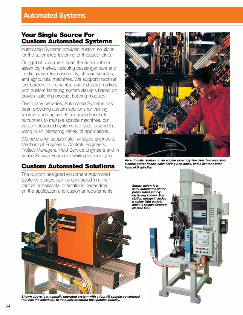
64
Your Single Source For Custom Automated SystemsAutomated Systems provides custom solutions for the automated fastening of threaded joints.
Our global customers span the entire vehicle assembly market, including passenger cars and trucks, power train assembly, off-road vehicles, and agricultural machines. We support machine tool builders in the vehicle and industrial markets with custom fastening system designs based on proven fastening product building modules.
Over many decades, Automated Systems has been providing custom solutions for training, service, and support. From single handheld nutrunners to multiple spindle machines, our custom designed systems are used around the world in an interesting variety of applications.
We have a full support staff of Sales Engineers, Mechanical Engineers, Controls Engineers, Project Managers, Field Service Engineers and In house Service Engineers waiting to serve you.
Custom Automated SolutionsThe custom designed equipment Automated Systems creates can be configured in either vertical or horizontal orientations depending on the application and customer requirements
Automated Systems
Shown below is a semi-automated water-pump subassembly fastening station. This station design includes a safety light curtain and a 4 spindle fixtured electric tool.
An automatic station on an engine assembly line uses two opposing electric power heads, each having 8 spindles, and a center power head of 6 spindles.
Shown above is a manually operated system with a four (4) spindle powerhead that has the capability to manually orientate the spindles radially.
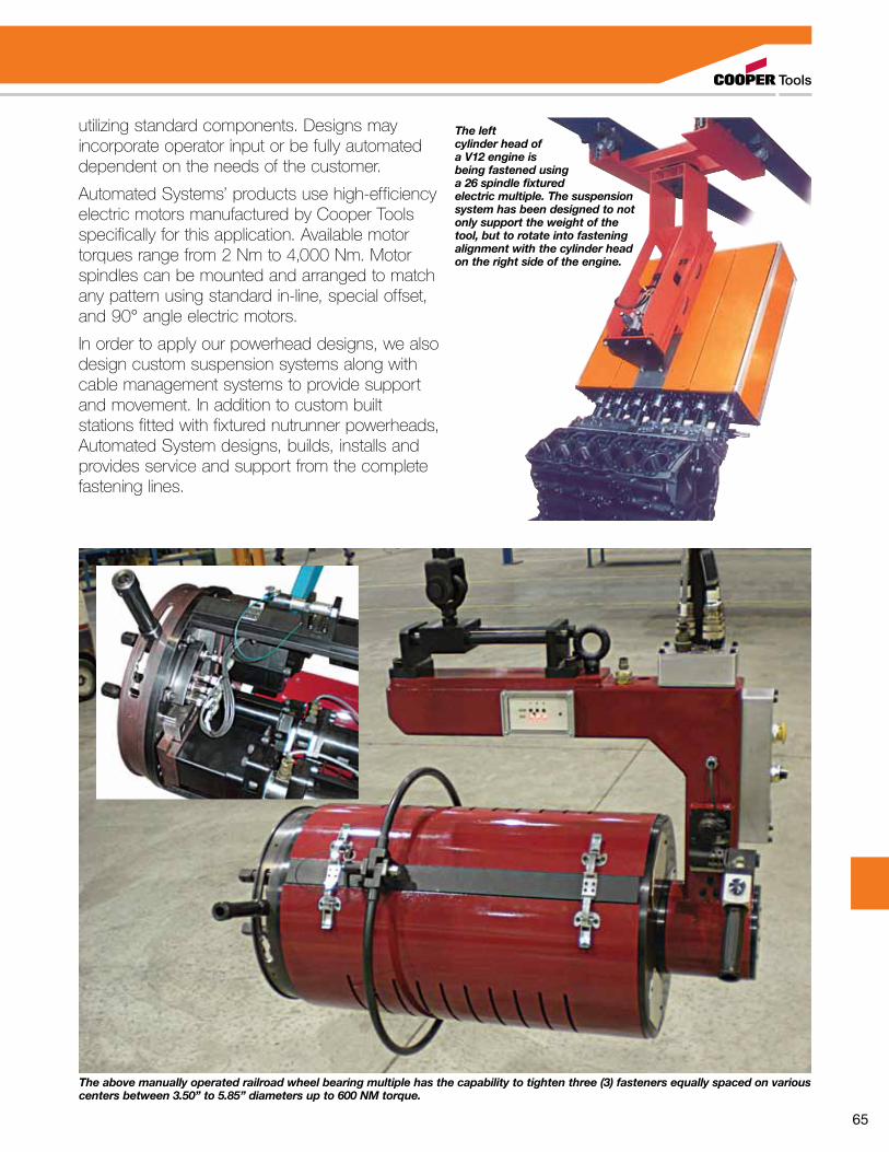
65
The left cylinder head of a V12 engine is being fastened using a 26 spindle fixtured electric multiple. The suspension system has been designed to not only support the weight of the tool, but to rotate into fastening alignment with the cylinder head on the right side of the engine.
utilizing standard components. Designs may incorporate operator input or be fully automated dependent on the needs of the customer.
Automated Systems’ products use high-efficiency electric motors manufactured by Cooper Tools specifically for this application. Available motor torques range from 2 Nm to 4,000 Nm. Motor spindles can be mounted and arranged to match any pattern using standard in-line, special offset, and 90° angle electric motors.
In order to apply our powerhead designs, we also design custom suspension systems along with cable management systems to provide support and movement. In addition to custom built stations fitted with fixtured nutrunner powerheads, Automated System designs, builds, installs and provides service and support from the complete fastening lines.
The above manually operated railroad wheel bearing multiple has the capability to tighten three (3) fasteners equally spaced on various centers between 3.50” to 5.85” diameters up to 600 NM torque.
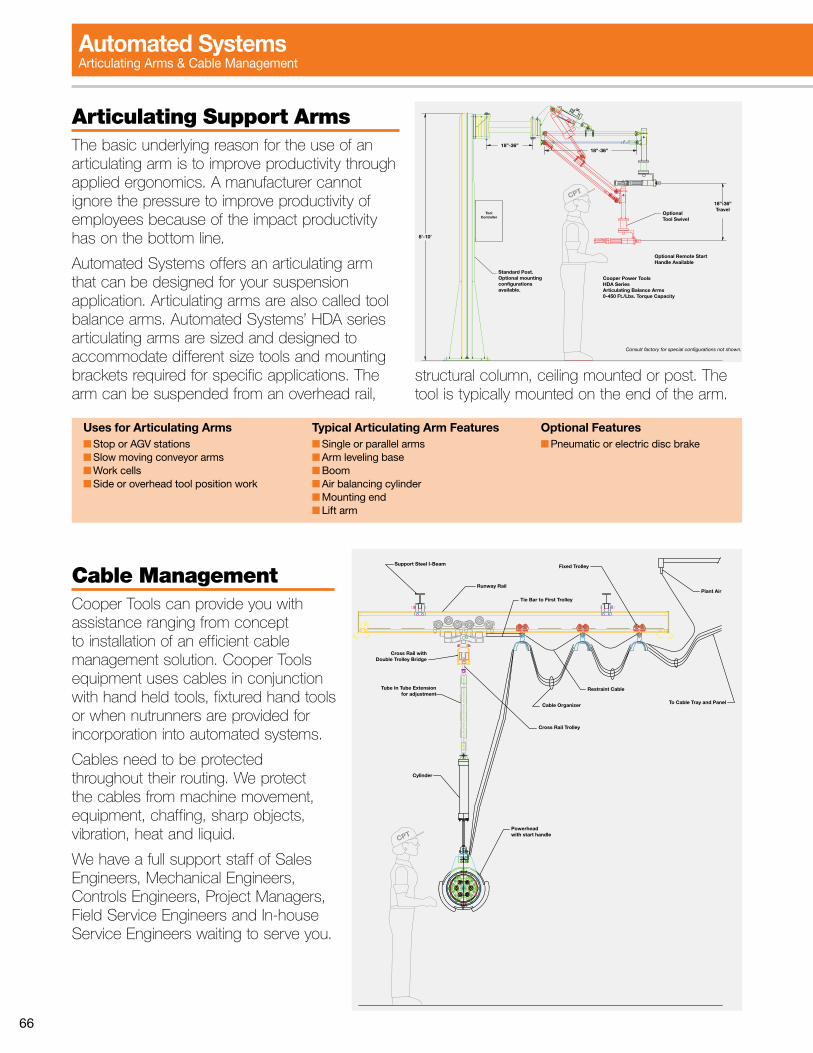
66
Articulating Support ArmsThe basic underlying reason for the use of an articulating arm is to improve productivity through applied ergonomics. A manufacturer cannot ignore the pressure to improve productivity of employees because of the impact productivity has on the bottom line.
Automated Systems offers an articulating arm that can be designed for your suspension application. Articulating arms are also called tool balance arms. Automated Systems’ HDA series articulating arms are sized and designed to accommodate different size tools and mounting brackets required for specific applications. The arm can be suspended from an overhead rail,
structural column, ceiling mounted or post. The tool is typically mounted on the end of the arm.
Uses for Articulating Arms■ Stop or AGV stations■ Slow moving conveyor arms■ Work cells ■ Side or overhead tool position work
Typical Articulating Arm Features■ Single or parallel arms■ Arm leveling base■ Boom■ Air balancing cylinder■ Mounting end■ Lift arm
Optional Features■ Pneumatic or electric disc brake
Cable ManagementCooper Tools can provide you with assistance ranging from concept to installation of an efficient cable management solution. Cooper Tools equipment uses cables in conjunction with hand held tools, fixtured hand tools or when nutrunners are provided for incorporation into automated systems.
Cables need to be protected throughout their routing. We protect the cables from machine movement, equipment, chaffing, sharp objects, vibration, heat and liquid.
We have a full support staff of Sales Engineers, Mechanical Engineers, Controls Engineers, Project Managers, Field Service Engineers and In-house Service Engineers waiting to serve you.
UII
DET
180
215
UII
DET
180
215
CPT
To Cable Tray and PanelCable Organizer
Fixed Trolley
Runway Rail
Support Steel I-Beam
Restraint Cable
Tie Bar to First Trolley
Tube In Tube Extensionfor adjustment
Cylinder
Powerhead with start handle
Cross Rail withDouble Trolley Bridge
Cross Rail Trolley
Plant Air
CPT
18”-36”
ToolController
8’-10’
18”-36”
18”-36”Travel
OptionalTool Swivel
Cooper Power ToolsHDA Series Articulating Balance Arms0-450 Ft./Lbs. Torque Capacity
Optional Remote Start Handle Available
Consult factory for special configurations not shown.
Standard Post.Optional mounting configurationsavailable.
Automated Systems Articulating Arms & Cable Management
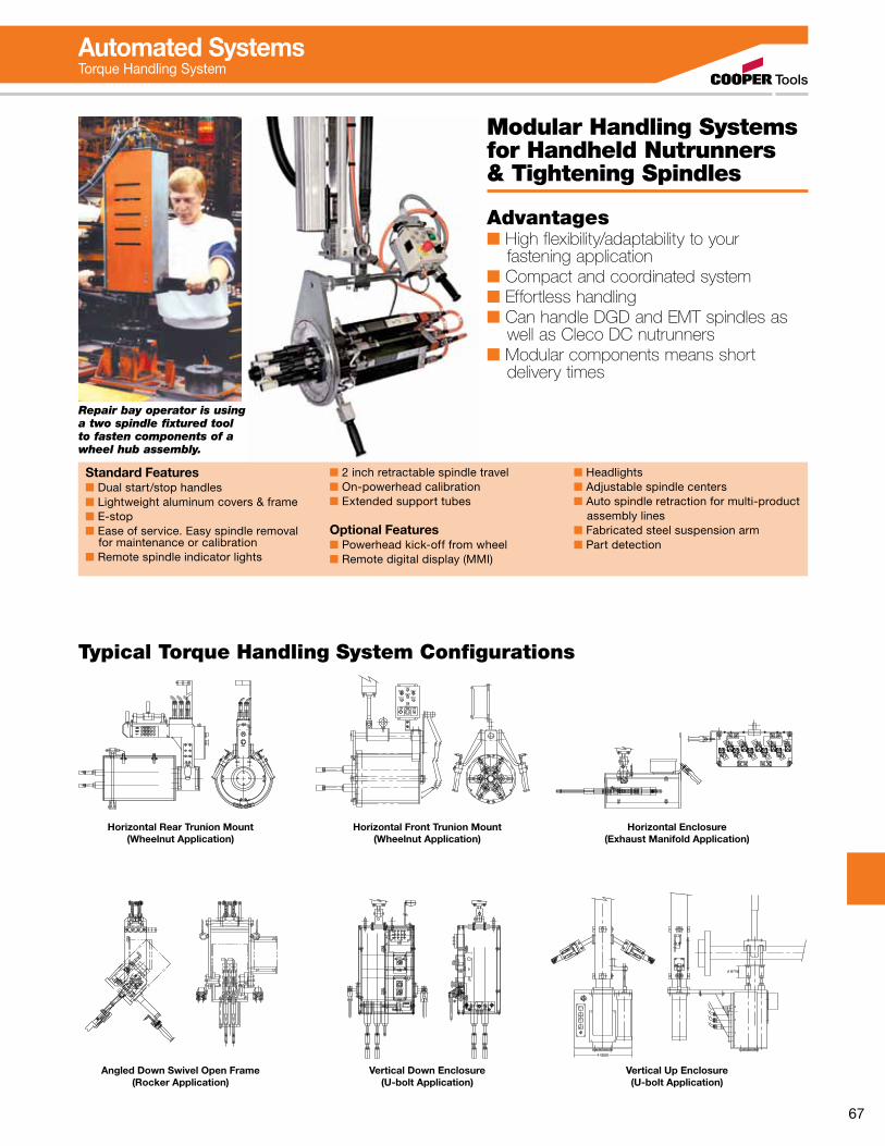
67
Modular Handling Systems for Handheld Nutrunners & Tightening Spindles
Advantages■ High flexibility/adaptability to your fastening application■ Compact and coordinated system■ Effortless handling■ Can handle DGD and EMT spindles as well as Cleco DC nutrunners■ Modular components means short delivery times
Repair bay operator is using a two spindle fixtured tool to fasten components of a wheel hub assembly.
Standard Features■ Dual start/stop handles■ Lightweight aluminum covers & frame■ E-stop■ Ease of service. Easy spindle removal for maintenance or calibration■ Remote spindle indicator lights
■ 2 inch retractable spindle travel■ On-powerhead calibration■ Extended support tubes
Optional Features■ Powerhead kick-off from wheel■ Remote digital display (MMI)
■ Headlights■ Adjustable spindle centers■ Auto spindle retraction for multi-product assembly lines■ Fabricated steel suspension arm■ Part detection
Horizontal Rear Trunion Mount(Wheelnut Application)
Angled Down Swivel Open Frame(Rocker Application)
Horizontal Front Trunion Mount(Wheelnut Application)
Vertical Down Enclosure(U-bolt Application)
Horizontal Enclosure(Exhaust Manifold Application)
Vertical Up Enclosure(U-bolt Application)
Typical Torque Handling System Configurations
Automated Systems Torque Handling System
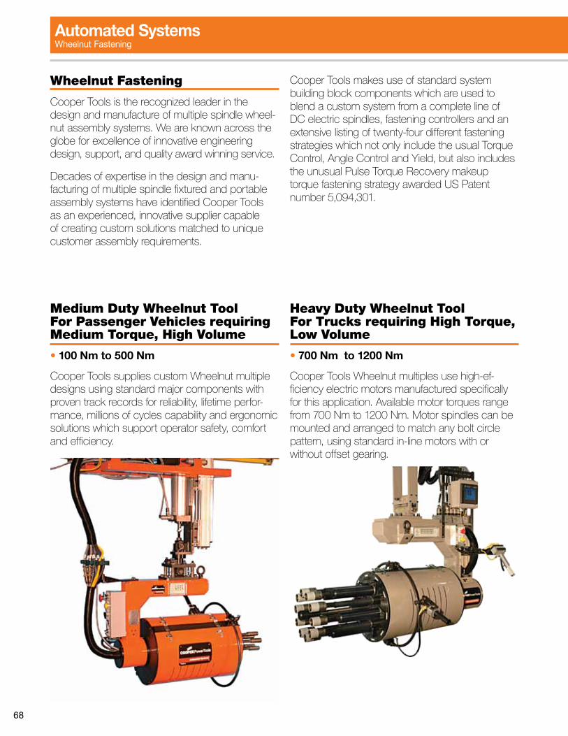
68
Wheelnut Fastening
Cooper Tools is the recognized leader in the design and manufacture of multiple spindle wheel-nut assembly systems. We are known across the globe for excellence of innovative engineering design, support, and quality award winning service.
Decades of expertise in the design and manu-facturing of multiple spindle fixtured and portable assembly systems have identified Cooper Tools as an experienced, innovative supplier capable of creating custom solutions matched to unique customer assembly requirements.
Cooper Tools makes use of standard system building block components which are used to blend a custom system from a complete line of DC electric spindles, fastening controllers and an extensive listing of twenty-four different fastening strategies which not only include the usual Torque Control, Angle Control and Yield, but also includes the unusual Pulse Torque Recovery makeup torque fastening strategy awarded US Patent number 5,094,301.
Medium Duty Wheelnut Tool For Passenger Vehicles requiring Medium Torque, High Volume
• 100 Nm to 500 Nm
Cooper Tools supplies custom Wheelnut multiple designs using standard major components with proven track records for reliability, lifetime perfor-mance, millions of cycles capability and ergonomic solutions which support operator safety, comfort and efficiency.
Heavy Duty Wheelnut Tool For Trucks requiring High Torque, Low Volume
• 700 Nm to 1200 Nm
Cooper Tools Wheelnut multiples use high-ef-ficiency electric motors manufactured specifically for this application. Available motor torques range from 700 Nm to 1200 Nm. Motor spindles can be mounted and arranged to match any bolt circle pattern, using standard in-line motors with or without offset gearing.
Automated SystemsWheelnut Fastening
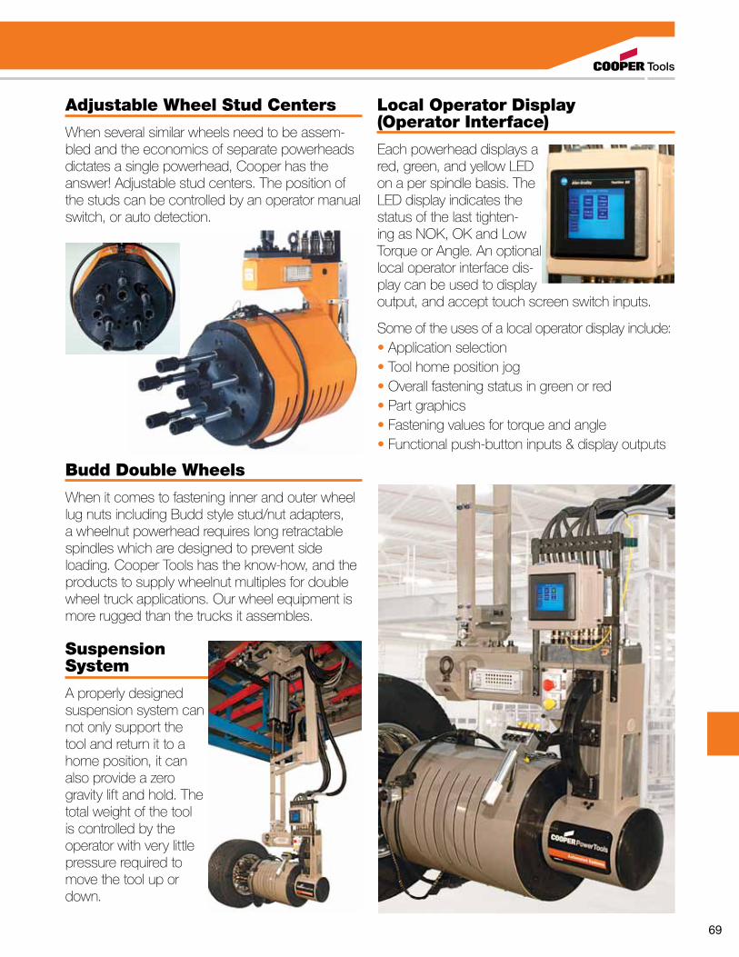
69
Adjustable Wheel Stud Centers
When several similar wheels need to be assem-bled and the economics of separate powerheads dictates a single powerhead, Cooper has the answer! Adjustable stud centers. The position of the studs can be controlled by an operator manual switch, or auto detection.
Budd Double Wheels
When it comes to fastening inner and outer wheel lug nuts including Budd style stud/nut adapters, a wheelnut powerhead requires long retractable spindles which are designed to prevent side loading. Cooper Tools has the know-how, and the products to supply wheelnut multiples for double wheel truck applications. Our wheel equipment is more rugged than the trucks it assembles.
Suspension System
A properly designed suspension system can not only support the tool and return it to a home position, it can also provide a zero gravity lift and hold. The total weight of the tool is controlled by the operator with very little pressure required to move the tool up or down.
Local Operator Display (Operator Interface)
Each powerhead displays a red, green, and yellow LED on a per spindle basis. The LED display indicates the status of the last tighten-ing as NOK, OK and Low Torque or Angle. An optional local operator interface dis-play can be used to display output, and accept touch screen switch inputs.
Some of the uses of a local operator display include:• Application selection• Tool home position jog• Overall fastening status in green or red• Part graphics• Fastening values for torque and angle• Functional push-button inputs & display outputs
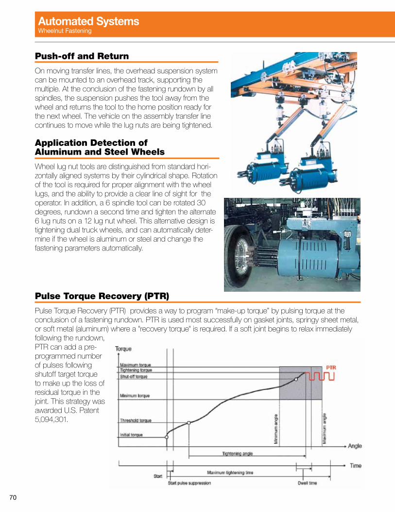
70
Pulse Torque Recovery (PTR)
Pulse Torque Recovery (PTR) provides a way to program “make-up torque” by pulsing torque at the conclusion of a fastening rundown. PTR is used most successfully on gasket joints, springy sheet metal, or soft metal (aluminum) where a "recovery torque" is required. If a soft joint begins to relax immediately following the rundown, PTR can add a pre-programmed number of pulses following shutoff target torque to make up the loss of residual torque in the joint. This strategy was awarded U.S. Patent 5,094,301.
Push-off and Return
On moving transfer lines, the overhead suspension system can be mounted to an overhead track, supporting the multiple. At the conclusion of the fastening rundown by all spindles, the suspension pushes the tool away from the wheel and returns the tool to the home position ready for the next wheel. The vehicle on the assembly transfer line continues to move while the lug nuts are being tightened.
Application Detection of Aluminum and Steel Wheels
Wheel lug nut tools are distinguished from standard hori-zontally aligned systems by their cylindrical shape. Rotation of the tool is required for proper alignment with the wheel lugs, and the ability to provide a clear line of sight for the operator. In addition, a 6 spindle tool can be rotated 30 degrees, rundown a second time and tighten the alternate 6 lug nuts on a 12 lug nut wheel. This alternative design is tightening dual truck wheels, and can automatically deter-mine if the wheel is aluminum or steel and change the fastening parameters automatically.
Automated SystemsWheelnut Fastening
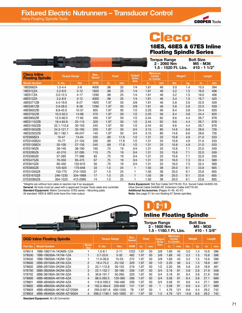
71
Fixtured Electric Nutrunners – Transducer ControlInline Floating Spindle Tools
18ES, 48ES & 67ES Inline Floating Spindle SeriesTorque Range Bolt Size 2 - 2060 Nm M5 - M36 1.5 - 1520 Ft. Lbs. #10 - 1 1/2”
DGD Inline Floating Spindle Torque Range Max.Speed Float Output
DriveSize
MinimumCenter
to CenterWeight Length
Part No. Model Number Motor Size ft. lbs. Nm RPM in. mm in. mm lbs. kg in. mm
578514 1BB-1B011A-1K3MS-1ZA 1 1.5-8.1 2-11 1222 1.97 50 3/8 1.69 43 3.0 1.4 15.6 396578500 1BB-1B030A-1K1M-1ZA 1 3.7-23.6 5-32 462 1.97 50 3/8 1.69 43 3.2 1.5 15.6 396578502 1BB-1B050A-1K2M-1ZA 1 11.0-39.0 15-53 272 1.97 50 3/8 1.69 43 3.2 1.5 15.6 396578600 2BB-2B100A-2K1M-2ZA 2 18.4-75.2 25-102 329 1.97 50 1/2 2.20 56 3.4 1.5 18.9 481578602 2BB-2B150A-2K2M-2ZA 2 22.1-112.8 30-153 219 1.97 50 1/2 2.20 56 5.8 2.6 18.9 481578700 3BB-3B260A-3K2M-3ZA 3 22.1-132.7 30-180 339 1.97 50 3/4 3.18 81 5.8 2.6 21.9 558578702 3BB-3B180A-3K1M-3ZA 3 36.8-191.7 50-260 220 1.97 50 3/4 3.18 81 8.4 3.8 21.9 558578800 4BB-4B360A-4K1M-4ZA 4 88.5-265.5 120-360 266 1.97 50 3/4 3.58 91 8.4 3.8 27.1 689578801 4BB-4B460A-4K2M-4ZA 4 118.0-339.2 160-460 209 1.97 50 3/4 3.58 91 9.6 4.4 27.1 689578802 4BB-4B630A-4K2M-4ZA 4 162.2-464.6 220-630 141 1.97 50 1 3.58 91 9.6 4.4 27.1 689578803 4BB-4B360A-4K1M-4Z1250A 4 295.0-921.8 400-1250 78 1.97 50 1 4.76 121 9.6 4.4 29.2 742578804 4BB-4B460A-4K2M-4Z1600A 4 398.2-1180.1 540-1600 61 1.97 50 1.5 4.76 121 14.6 6.6 29.2 742
Standard Equipment: Air LB Connector
Inline Floating SpindleTorque Range Bolt Size 2 - 1600 Nm M5 - M30 1.5 - 1180.1 Ft. Lbs. #10 - 1 3/8”
Cleco Inline Floating Spindle Torque Range Max.
Speed Float OutputDriveSize
MinimumCenter
to CenterWeight* Length
Model Number ft. lbs. Nm RPM in. mm in. mm lbs. kg in. mm
18ES06ZA 1.5-4.4 2-6 4000 .98 25 1/4 1.81 46 3.0 1.4 15.5 39418ES12ZA 2.2-8.9 3-12 1820 .98 25 1/4 1.81 46 3.2 1.5 16.0 40618ES17ZA 3.0-12.5 4-17 1290 .98 25 1/4 1.81 46 3.2 1.5 16.0 40648ES12ZA 2.2-8.9 3-12 4000 .98 25 1/4 1.81 46 3.4 1.5 16.7 42548ES271ZB 4.4-19.9 6-27 1820 1.97 50 3/8 1.81 46 5.8 2.6 22.0 55948ES361ZB 5.9-28.0 8-38 1290 1.97 50 3/8 1.81 46 5.8 2.6 22.0 55948ES602ZB 8.8-42.0 12-57 855 1.97 50 1/2 2.20 56 8.4 3.8 24.4 62048ES702ZB 10.3-50.2 14-68 570 1.97 50 1/2 2.20 56 8.4 3.8 24.4 62048ES802ZB 12.5-60.5 17-82 450 1.97 50 1/2 2.44 62 9.6 4.4 26.7 67848ES1152ZB 18.4-84.8 25-115 320 1.97 50 1/2 2.44 62 9.6 4.4 26.7 67848ES1502ZB 22.1-110.6 30-150 245 1.97 50 1/2 2.44 62 9.6 4.4 26.7 67848ES1653ZB 24.3-121.7 33-165 220 1.97 50 3/4 3.15 80 14.6 6.6 28.6 72648ES2503ZB 36.1-182.1 49-247 145 1.97 50 3/4 3.15 80 14.6 6.6 28.6 72667ES65BZ4 10-47 13-64 535 .69 17.6 1/2 1.31 33 10.8 4.9 21.0 53367ES105BZ4 15-77 21-104 330 .69 17.6 1/2 1.31 33 10.8 4.9 21.0 53367ES135BZ4 20-100 27-135 245 .69 17.6 1/2 1.31 33 10.8 4.9 21.0 53367ES190Z6 28-140 38-190 165 .75 19 3/4 1.31 33 15.6 7.1 22.0 55967ES285Z6 42-210 57-285 115 .75 19 3/4 1.31 33 15.6 7.1 22.0 55967ES385Z6 57-285 77-386 83 .75 19 3/4 1.31 33 15.6 7.1 22.0 55967ES475Z6 70-350 95-475 67 .75 19 3/4 1.31 33 16.0 7.3 22.4 56967ES610Z6 90-450 122-610 50 .75 19 3/4 1.31 33 16.0 7.3 22.4 56967ES850Z8 125-625 170-848 33 1.0 25 1 1.50 38 20.0 9.1 23.8 60567ES1050Z8 155-775 210-1050 27 1.0 25 1 1.50 38 20.0 9.1 23.8 60567ES1670Z8 246-1230 334-1668 17 1.0 25 1 1.50 38 20.0 9.1 23.8 60567ES2060Z8 304-1520 412-2060 14 1.0 25 1 1.50 38 20.0 9.1 23.8 605
*Weights are without tool cable or reaction bar if so equipped. General: All tools must be used with a approved Cooper Tools cable and controller.Standard Equipment: Matrix Connector; 67ES series – Mounting plate.All standard 18ES & 48ES tools have thru hole output.
Extra Equipment: Std.Tool Cable 542778-XX, R.A. Swivel Cable 544055-XX, Inline Swivel Cable 544056-XX. Extension Cable 542779-XX. Additional Accessories: (Pages 41-49, 45-47)Note: See page 31 for non-floating 67 Series spindles.
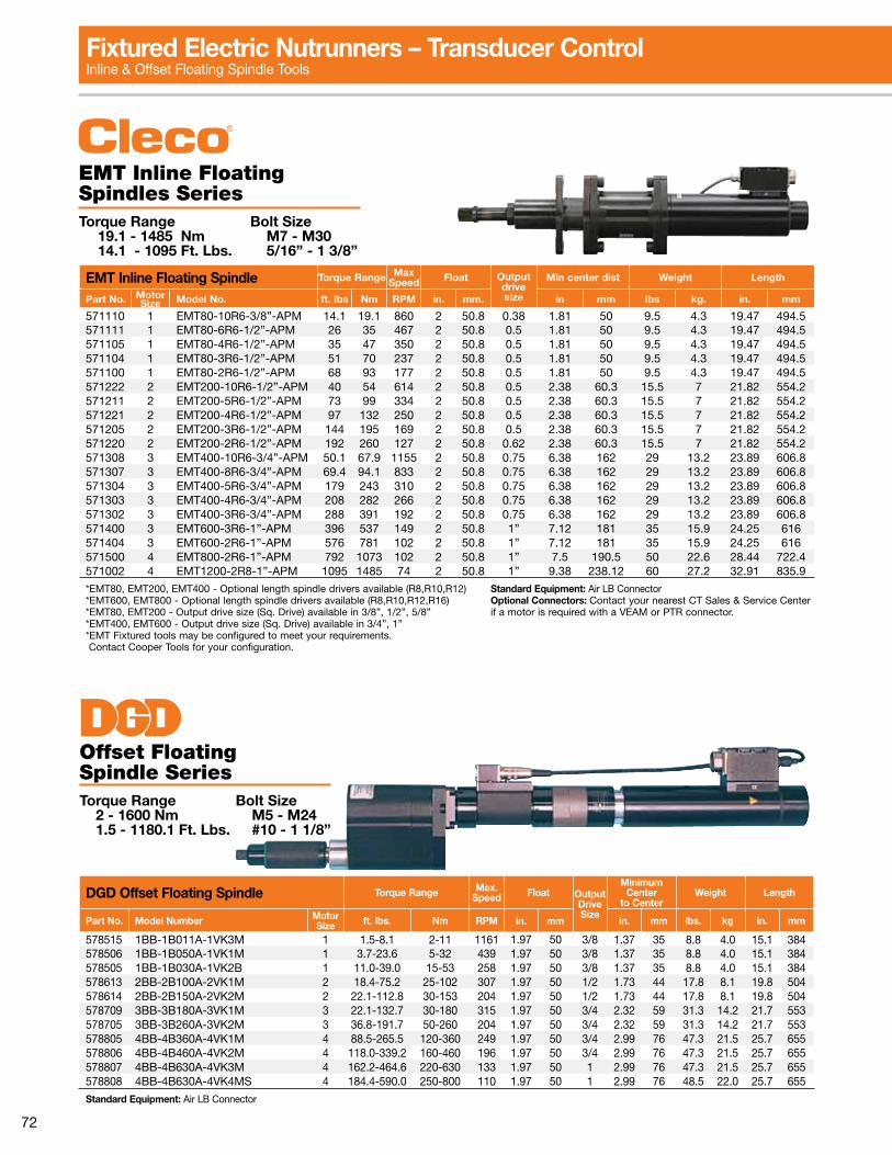
72
DGD Offset Floating Spindle Torque Range Max.Speed Float Output
DriveSize
MinimumCenter
to CenterWeight Length
Part No. Model Number Motor Size ft. lbs. Nm RPM in. mm in. mm lbs. kg in. mm
578515 1BB-1B011A-1VK3M 1 1.5-8.1 2-11 1161 1.97 50 3/8 1.37 35 8.8 4.0 15.1 384578506 1BB-1B050A-1VK1M 1 3.7-23.6 5-32 439 1.97 50 3/8 1.37 35 8.8 4.0 15.1 384578505 1BB-1B030A-1VK2B 1 11.0-39.0 15-53 258 1.97 50 3/8 1.37 35 8.8 4.0 15.1 384578613 2BB-2B100A-2VK1M 2 18.4-75.2 25-102 307 1.97 50 1/2 1.73 44 17.8 8.1 19.8 504578614 2BB-2B150A-2VK2M 2 22.1-112.8 30-153 204 1.97 50 1/2 1.73 44 17.8 8.1 19.8 504578709 3BB-3B180A-3VK1M 3 22.1-132.7 30-180 315 1.97 50 3/4 2.32 59 31.3 14.2 21.7 553578705 3BB-3B260A-3VK2M 3 36.8-191.7 50-260 204 1.97 50 3/4 2.32 59 31.3 14.2 21.7 553578805 4BB-4B360A-4VK1M 4 88.5-265.5 120-360 249 1.97 50 3/4 2.99 76 47.3 21.5 25.7 655578806 4BB-4B460A-4VK2M 4 118.0-339.2 160-460 196 1.97 50 3/4 2.99 76 47.3 21.5 25.7 655578807 4BB-4B630A-4VK3M 4 162.2-464.6 220-630 133 1.97 50 1 2.99 76 47.3 21.5 25.7 655578808 4BB-4B630A-4VK4MS 4 184.4-590.0 250-800 110 1.97 50 1 2.99 76 48.5 22.0 25.7 655
Standard Equipment: Air LB Connector
Offset Floating Spindle SeriesTorque Range Bolt Size 2 - 1600 Nm M5 - M24 1.5 - 1180.1 Ft. Lbs. #10 - 1 1/8”
EMT Inline Floating Spindles Series Torque Range Bolt Size 19.1 - 1485 Nm M7 - M30 14.1 - 1095 Ft. Lbs. 5/16” - 1 3/8”
EMT Inline Floating Spindle Torque Range Max Speed Float Output
drive size
Min center dist Weight Length
Part No. Motor Size Model No. ft. lbs Nm RPM in. mm. in mm lbs kg. in. mm
571110 1 EMT80-10R6-3/8”-APM 14.1 19.1 860 2 50.8 0.38 1.81 50 9.5 4.3 19.47 494.5571111 1 EMT80-6R6-1/2”-APM 26 35 467 2 50.8 0.5 1.81 50 9.5 4.3 19.47 494.5571105 1 EMT80-4R6-1/2”-APM 35 47 350 2 50.8 0.5 1.81 50 9.5 4.3 19.47 494.5571104 1 EMT80-3R6-1/2”-APM 51 70 237 2 50.8 0.5 1.81 50 9.5 4.3 19.47 494.5571100 1 EMT80-2R6-1/2”-APM 68 93 177 2 50.8 0.5 1.81 50 9.5 4.3 19.47 494.5571222 2 EMT200-10R6-1/2”-APM 40 54 614 2 50.8 0.5 2.38 60.3 15.5 7 21.82 554.2571211 2 EMT200-5R6-1/2”-APM 73 99 334 2 50.8 0.5 2.38 60.3 15.5 7 21.82 554.2571221 2 EMT200-4R6-1/2”-APM 97 132 250 2 50.8 0.5 2.38 60.3 15.5 7 21.82 554.2571205 2 EMT200-3R6-1/2”-APM 144 195 169 2 50.8 0.5 2.38 60.3 15.5 7 21.82 554.2571220 2 EMT200-2R6-1/2”-APM 192 260 127 2 50.8 0.62 2.38 60.3 15.5 7 21.82 554.2571308 3 EMT400-10R6-3/4”-APM 50.1 67.9 1155 2 50.8 0.75 6.38 162 29 13.2 23.89 606.8571307 3 EMT400-8R6-3/4”-APM 69.4 94.1 833 2 50.8 0.75 6.38 162 29 13.2 23.89 606.8571304 3 EMT400-5R6-3/4”-APM 179 243 310 2 50.8 0.75 6.38 162 29 13.2 23.89 606.8571303 3 EMT400-4R6-3/4”-APM 208 282 266 2 50.8 0.75 6.38 162 29 13.2 23.89 606.8571302 3 EMT400-3R6-3/4”-APM 288 391 192 2 50.8 0.75 6.38 162 29 13.2 23.89 606.8571400 3 EMT600-3R6-1”-APM 396 537 149 2 50.8 1” 7.12 181 35 15.9 24.25 616571404 3 EMT600-2R6-1”-APM 576 781 102 2 50.8 1” 7.12 181 35 15.9 24.25 616571500 4 EMT800-2R6-1”-APM 792 1073 102 2 50.8 1” 7.5 190.5 50 22.6 28.44 722.4571002 4 EMT1200-2R8-1”-APM 1095 1485 74 2 50.8 1” 9.38 238.12 60 27.2 32.91 835.9
*EMT80, EMT200, EMT400 - Optional length spindle drivers available (R8,R10,R12) *EMT600, EMT800 - Optional length spindle drivers available (R8,R10,R12,R16)*EMT80, EMT200 - Output drive size (Sq. Drive) available in 3/8”, 1/2”, 5/8”*EMT400, EMT600 - Output drive size (Sq. Drive) available in 3/4”, 1”*EMT Fixtured tools may be configured to meet your requirements. Contact Cooper Tools for your configuration.
Standard Equipment: Air LB ConnectorOptional Connectors: Contact your nearest CT Sales & Service Center if a motor is required with a VEAM or PTR connector.
Fixtured Electric Nutrunners – Transducer ControlInline & Offset Floating Spindle Tools

73
Fixtured Electric Nutrunners – Transducer ControlOffset & Right Angle Floating Spindle Tools
Right 18EA, 48EA & 67EA Angle Floating Spindle Torque Range Bolt Size 5.1 - 255 Nm M7 - M18 3.7 - 188.1 Ft. Lbs. 1/4” - 3/4”
Cleco Angle Floating Spindle Torque Range Max.
Speed Float OutputDriveSize
MinimumCenter
to CenterWeight* Length
Model Number ft. lbs. Nm RPM in. mm in. mm lbs. kg in. mm
18EA16S131 3.7-12.5 5.1-17 1225 .98 25 3/8 1.10 28 4.4 2.0 16.0 40618EA23S131 5.3-17.7 7.2-24 860 .98 25 3/8 1.10 28 4.4 2.0 16.0 40618EA30S131 4.4-22.8 6.0-31 655 .98 25 3/8 1.10 28 4.4 2.0 16.0 40648EA37S231 5.9-28.0 8.0-38 1225 .74 19 3/8 1.33 34 5.2 2.4 18.6 47448EA52S231 8.1-39.8 11-54 860 .74 19 3/8 1.33 34 5.2 2.4 18.6 47448EA53S341 8.1-39.8 11-54 850 .74 19 1/2 1.73 44 5.9 2.7 20.0 50948EA74S341 11.0-56.8 15-77 600 .74 19 1/2 1.73 44 5.9 2.7 20.0 50948EA95S341 14.7-72.2 20-98 460 .74 19 1/2 1.73 44 5.9 2.7 20.0 50948EA110S341 16.9-81.1 23-110 400 .74 19 1/2 1.73 44 7.2 3.3 20.5 52148EA135S461 20.6-101.7 28-138 270 .74 19 3/4 2.12 54 8.8 4.0 20.5 52248EA230S461 34.6-172.5 47-234 150 .74 19 3/4 2.12 54 10.3 4.7 22.1 56367EA150S461 22.1-110.6 30-150 210 .74 19 3/4 2.04 52 13.0 5.9 25.7 65567EA185S461 27.3-136.3 37-185 170 .74 19 3/4 2.04 52 13.0 5.9 25.7 65567EA210S461 31.0-154.8 42-210 155 .74 19 3/4 2.04 52 13.0 5.9 25.7 65567EA235S461 33.9-169.6 46-230 135 .74 19 3/4 2.04 52 13.0 5.9 25.7 65567EA255S461 40.6-188.1 55-255 115 .74 19 3/4 2.04 52 13.0 5.9 25.7 655
*Weights are without tool cable or reaction bar if so equipped. General: All tools must be used with a approved Cooper Tools cable and controller.Standard Equipment: Matrix Connector.
Extra Equipment: Std.Tool Cable 542778-XX, R.A. Swivel Cable 544055-XX, Inline Swivel Cable 544056-XX, Extension Cable 542779-XX. Additional Accessories: (Pages 41-49)
EMT Offset Floating Spindles Series Torque Range Bolt Size 19.1 - 1073 Nm M7 - M27 14.1 - 792 Ft. Lbs. 5/16” - 1 1/4”
EMT Offset Floating Spindles Torque Range Max Speed Float Output
drive size
Min center dist Weight Length
Part No. Motor Size Model No ft. lbs Nm RPM in. mm. in mm lbs kg. in. mm
571112 1 EMT80-10-OS75-3/8”-APM 14.1 19.1 860 2 50.8 0.38 1.06 27 11 4.9 21.51 546.3571113 1 EMT80-6-OS75-3/8”-APM 26 35 467 2 50.8 0.38 1.06 27 11 4.9 21.51 546.3571114 1 EMT80-4-OS75-1/2”-APM 35 47 350 2 50.8 0.5 1.06 27 11 4.9 21.51 546.3571115 1 EMT80-3-OS75-1/2”-APM 51 70 237 2 50.8 0.5 1.06 27 11 4.9 21.51 546.3571223 2 EMT200-10-OS150-1/2”-APM 40 54 614 2 50.8 0.5 1.5 38.1 21 9.5 25.26 641.6571215 2 EMT200-5-OS150-1/2”-APM 73 99 334 2 50.8 0.5 1.5 38.1 21 9.5 25.26 641.6571224 2 EMT200-4-OS150-1/2”-APM 97 132 250 2 50.8 0.5 1.5 38.1 21 9.5 25.26 641.6571225 2 EMT200-3-OS250-1/2”-APM 144 195 169 2 50.8 0.5 1.88 47.6 21 9.5 25.26 641.6571201 2 EMT200-2-OS250-5/8”-APM 192 260 127 2 50.8 0.62 1.88 47.6 21 9.5 25.26 641.6571309 3 EMT400-5-OS400-3/4”-APM 179 243 310 2 50.8 0.75 4.75 120.6 39 17.7 30 762571310 3 EMT400-4-OS400-3/4”-APM 208 282 266 2 50.8 0.75 4.75 120.6 39 17.7 30 762571311 3 EMT400-3-OS400-3/4”-APM 288 391 192 2 50.8 0.75 4.75 120.6 39 17.7 30 762571410 3 EMT600-3-OS600-1”-APM 396 537 149 2 50.8 1” 4.75 120.6 45 20.4 30.38 771.6571413 3 EMT600-2-OS600-1”-APM 576 781 102 2 50.8 1” 4.75 120.6 45 20.4 30.38 771.6571503 4 EMT800-2-OS800-1”-APM 792 1073 102 2 50.8 1” 5.62 142.7 90 40.8 34.56 877.8
*EMT Fixtured Offset tools may be configured to meet your requirements. Contact CooperTools for your configuration. Standard Equipment: Air LB Connector. Optional Connectors: Contact your nearest CT Sales & Service Center if a motor is required with a VEAM or PTR connector.
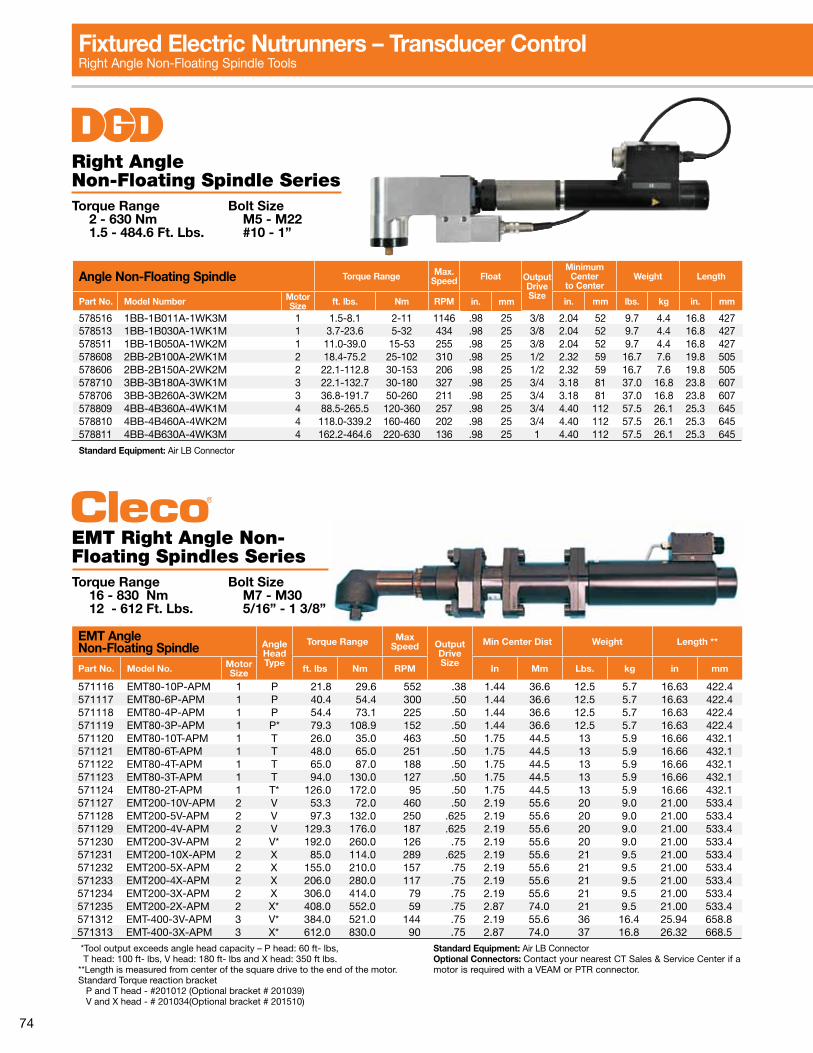
74
Fixtured Electric Nutrunners – Transducer ControlRight Angle Non-Floating Spindle Tools
Angle Non-Floating Spindle Torque Range Max.Speed Float Output
DriveSize
MinimumCenter
to CenterWeight Length
Part No. Model Number Motor Size ft. lbs. Nm RPM in. mm in. mm lbs. kg in. mm
578516 1BB-1B011A-1WK3M 1 1.5-8.1 2-11 1146 .98 25 3/8 2.04 52 9.7 4.4 16.8 427578513 1BB-1B030A-1WK1M 1 3.7-23.6 5-32 434 .98 25 3/8 2.04 52 9.7 4.4 16.8 427578511 1BB-1B050A-1WK2M 1 11.0-39.0 15-53 255 .98 25 3/8 2.04 52 9.7 4.4 16.8 427578608 2BB-2B100A-2WK1M 2 18.4-75.2 25-102 310 .98 25 1/2 2.32 59 16.7 7.6 19.8 505578606 2BB-2B150A-2WK2M 2 22.1-112.8 30-153 206 .98 25 1/2 2.32 59 16.7 7.6 19.8 505578710 3BB-3B180A-3WK1M 3 22.1-132.7 30-180 327 .98 25 3/4 3.18 81 37.0 16.8 23.8 607578706 3BB-3B260A-3WK2M 3 36.8-191.7 50-260 211 .98 25 3/4 3.18 81 37.0 16.8 23.8 607578809 4BB-4B360A-4WK1M 4 88.5-265.5 120-360 257 .98 25 3/4 4.40 112 57.5 26.1 25.3 645578810 4BB-4B460A-4WK2M 4 118.0-339.2 160-460 202 .98 25 3/4 4.40 112 57.5 26.1 25.3 645578811 4BB-4B630A-4WK3M 4 162.2-464.6 220-630 136 .98 25 1 4.40 112 57.5 26.1 25.3 645
Standard Equipment: Air LB Connector
Right Angle Non-Floating Spindle SeriesTorque Range Bolt Size 2 - 630 Nm M5 - M22 1.5 - 484.6 Ft. Lbs. #10 - 1”
EMT Right Angle Non-Floating Spindles Series Torque Range Bolt Size 16 - 830 Nm M7 - M30 12 - 612 Ft. Lbs. 5/16” - 1 3/8”
EMT Angle Non-Floating Spindle Angle
Head Type
Torque Range Max Speed Output
Drive Size
Min Center Dist Weight Length **
Part No. Model No. Motor Size ft. lbs Nm RPM In Mm Lbs. kg in mm
571116 EMT80-10P-APM 1 P 21.8 29.6 552 .38 1.44 36.6 12.5 5.7 16.63 422.4571117 EMT80-6P-APM 1 P 40.4 54.4 300 .50 1.44 36.6 12.5 5.7 16.63 422.4571118 EMT80-4P-APM 1 P 54.4 73.1 225 .50 1.44 36.6 12.5 5.7 16.63 422.4571119 EMT80-3P-APM 1 P* 79.3 108.9 152 .50 1.44 36.6 12.5 5.7 16.63 422.4571120 EMT80-10T-APM 1 T 26.0 35.0 463 .50 1.75 44.5 13 5.9 16.66 432.1571121 EMT80-6T-APM 1 T 48.0 65.0 251 .50 1.75 44.5 13 5.9 16.66 432.1571122 EMT80-4T-APM 1 T 65.0 87.0 188 .50 1.75 44.5 13 5.9 16.66 432.1571123 EMT80-3T-APM 1 T 94.0 130.0 127 .50 1.75 44.5 13 5.9 16.66 432.1571124 EMT80-2T-APM 1 T* 126.0 172.0 95 .50 1.75 44.5 13 5.9 16.66 432.1571127 EMT200-10V-APM 2 V 53.3 72.0 460 .50 2.19 55.6 20 9.0 21.00 533.4571128 EMT200-5V-APM 2 V 97.3 132.0 250 .625 2.19 55.6 20 9.0 21.00 533.4571129 EMT200-4V-APM 2 V 129.3 176.0 187 .625 2.19 55.6 20 9.0 21.00 533.4571230 EMT200-3V-APM 2 V* 192.0 260.0 126 .75 2.19 55.6 20 9.0 21.00 533.4571231 EMT200-10X-APM 2 X 85.0 114.0 289 .625 2.19 55.6 21 9.5 21.00 533.4571232 EMT200-5X-APM 2 X 155.0 210.0 157 .75 2.19 55.6 21 9.5 21.00 533.4571233 EMT200-4X-APM 2 X 206.0 280.0 117 .75 2.19 55.6 21 9.5 21.00 533.4571234 EMT200-3X-APM 2 X 306.0 414.0 79 .75 2.19 55.6 21 9.5 21.00 533.4571235 EMT200-2X-APM 2 X* 408.0 552.0 59 .75 2.87 74.0 21 9.5 21.00 533.4571312 EMT-400-3V-APM 3 V* 384.0 521.0 144 .75 2.19 55.6 36 16.4 25.94 658.8571313 EMT-400-3X-APM 3 X* 612.0 830.0 90 .75 2.87 74.0 37 16.8 26.32 668.5
*Tool output exceeds angle head capacity – P head: 60 ft- lbs, T head: 100 ft- lbs, V head: 180 ft- lbs and X head: 350 ft lbs.**Length is measured from center of the square drive to the end of the motor.Standard Torque reaction bracket P and T head - #201012 (Optional bracket # 201039) V and X head - # 201034(Optional bracket # 201510)
Standard Equipment: Air LB ConnectorOptional Connectors: Contact your nearest CT Sales & Service Center if a motor is required with a VEAM or PTR connector.
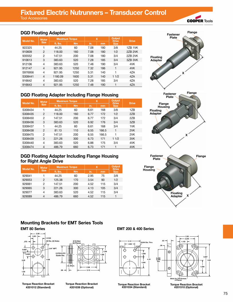
75
Fixtured Electric Nutrunners – Transducer ControlTool Accessories
X
FlangeFastener
Plate
Floating Adapter
X
FlangeFastener Plate
Floating Adapter
Flange Housing
X
FlangeFastener Plate
Floating Adapter
Flange Housing
Model No. Motor Size
Maximum Torque X OutputDriveSize
Driveft. lbs. Nm in. mm
922325 1 44.25 60 7.08 180 3/8 1ZB 1VK910609 2 118.00 160 7.08 180 1/2 2ZB 2VK935552 2 147.51 200 7.08 180 3/4 2ZB 2VK910613 3 383.63 520 7.28 185 3/4 3ZB 3VK912106 4 383.63 520 7.48 190 3/4 4VK912147 4 921.95 1250 7.32 186 1 4VKS976956 4 921.95 1250 5.31 140 1 4ZAS308441 4 1180.09 1600 5.31 140 1 1/2 4ZA916642 4 383.63 520 7.28 185 3/4 4ZA916643 4 921.95 1250 7.48 190 1 4ZA
DGD Floating Adapter
Model No. Motor Size
Maximum Torque X OutputDriveSize
Driveft. lbs. Nm in. mm
S308434 1 44.25 60 6.61 168 3/8 1ZBS308435 2 118.00 160 6.77 172 1/2 2ZBS308450 2 147.51 200 6.77 172 3/4 2ZBS308436 3 383.63 520 6.92 176 3/4 3ZBS308437 1 44.25 60 6.61 168 3/4 1VKS308438 2 81.13 110 6.55 166.5 1 2VKS308475 2 147.51 200 6.55 166.5 1 2VKS308439 3 221.26 300 6.73 171 1 1/2 3VKS308440 4 383.63 520 6.88 175 3/4 4VKS308474 4 486.79 660 6.73 171 1 4VK
DGD Floating Adapter Including Flange Housing
Model No. Motor Size
Maximum Torque X OutputDriveSizeft. lbs. Nm in. mm
929041 1 44.25 60 2.95 75 3/8929053 2 125.38 170 3.54 90 1/2929061 2 147.51 200 4.52 115 3/4929065 3 221.26 300 4.13 105 3/4929077 4 383.63 520 4.52 115 3/4929089 4 486.79 660 4.52 115 1
DGD Floating Adapter Including Flange Housing for Right Angle Drive
DIA.
.50
1.06
2.47
16.63 FOR EMT80-2P, -3P, -4P AND -6P
5.20
3/8 AVAILABLE1/2 SQ. DRIVE STANDARD
2.53 DIA
2.65
1.65
2.38
3.13
2.06
1.3125
.375
1.031
(4) Places
4.38
Torque Reaction Bracket#201012 (Standard)
Torque Reaction Bracket#201039 (Optional)
2.25
1.00
0.625
0.625
.50
.38
Guide Dia.2.375/2.373
3/4” NPT
5/16 Slot.38 Dia. (4) Holes
2.46
1.69
EMT80-10P-3/8-29PEMT80-6P-1/2-29PEMT80-4P-1/2-29PEMT80-3P-1/2-29P570409
570401570408570407
PART NO. MODEL Nm
108735529
ft-lbs
300
152225
rpm552
40
8054
22
EMT80-P FIXTUREDRIGHT ANGLE NUTRUNNERSWITH 29-PIN CONNECTOR
-P ANGLE HEAD CAPACITY: 60 FTLBSNOTE: TOOL OUTPUT EXCEEDS ANGLE HEAD CAPACITY
Mounting Brackets for EMT Series Tools
3.2483.250
.38
Slots for 3/8 Screws4-Places
Torque Reaction Bracket#201034 (Standard)
Torque Reaction Bracket#201510 (Optional)
1/2", 5/8', & 3/4 SQUARE DRIVE AVAILABLE
EMT200-V FIXTURED
WITH 29-PIN CONNECTORRIGHT ANGLE NUTRUNNERS
EMT200-10V-1/2-29PEMT200-5V-5/8-29PEMT200-4V-5/8-29PEMT200-3V-5/8-29P
200V98.DWG 11/97ACAD FILE:
570511570512
570507570513
PART NO. MODEL Nm
260.0176.0132.072.0
ft-lbs
187126
rpm
250460
129.3192.0
97.353.3
DIA.
21.00 FOR EMT200-2V, -3V, -4V AND -5V
3.69
1.67
.63
5.25
2.16
25/64 Dia. Thru
Dia.
3.12
4.19
1.640
1.000
1.500
2.73
3.25 DIA
-V ANGLE HEAD CAPACITY: 180 FTLBSNOTE: TOOL OUTPUT EXCEEDS ANGLE HEAD CAPACITY
4.84
3.897
1.949
3.38
.63 1.125
2.250
2.19DIA.
EMT 80 Series EMT 200 & 400 Series
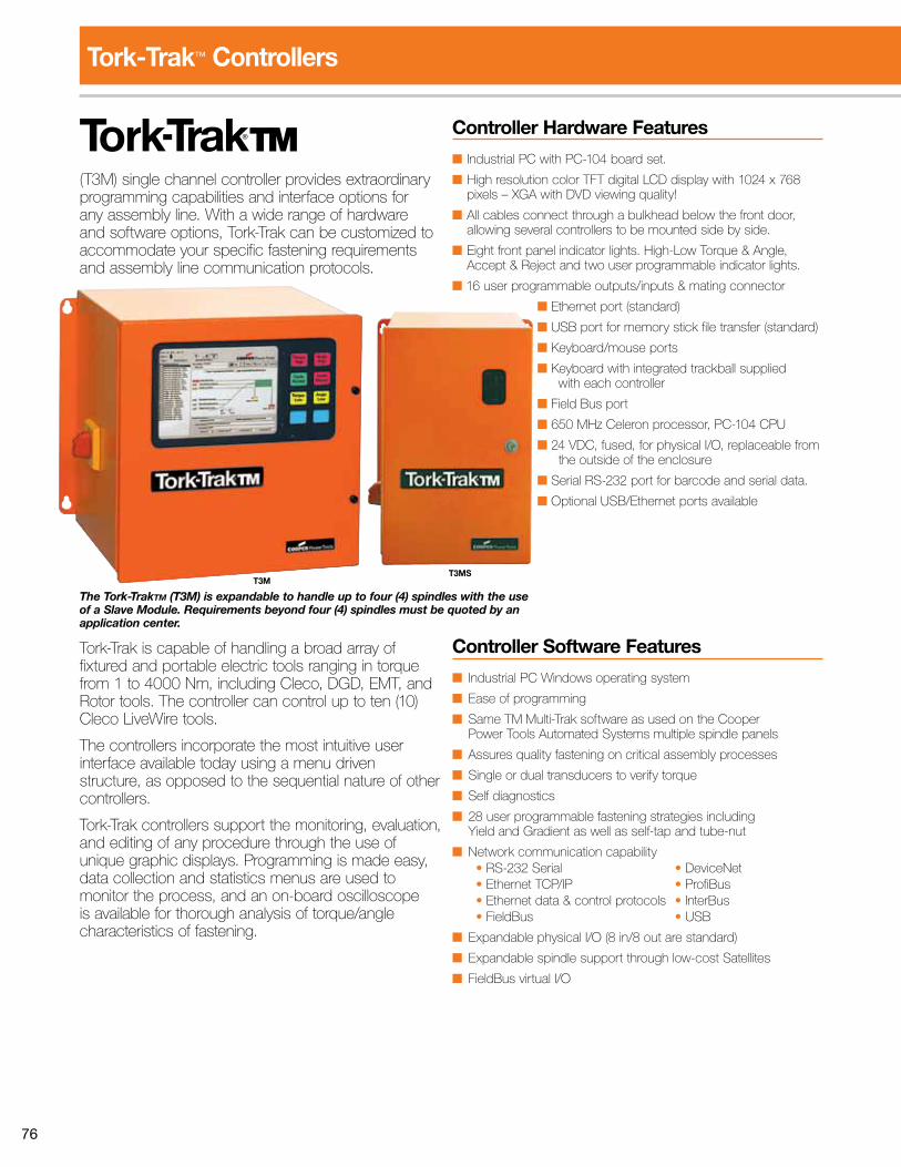
76
Controller Hardware Features
■ Industrial PC with PC-104 board set.
■ High resolution color TFT digital LCD display with 1024 x 768 pixels – XGA with DVD viewing quality!
■ All cables connect through a bulkhead below the front door, allowing several controllers to be mounted side by side.
■ Eight front panel indicator lights. High-Low Torque & Angle, Accept & Reject and two user programmable indicator lights.
■ 16 user programmable outputs/inputs & mating connector
■ Ethernet port (standard)
■ USB port for memory stick file transfer (standard)
■ Keyboard/mouse ports
■ Keyboard with integrated trackball supplied with each controller
■ Field Bus port
■ 650 MHz Celeron processor, PC-104 CPU
■ 24 VDC, fused, for physical I/O, replaceable from the outside of the enclosure
■ Serial RS-232 port for barcode and serial data.
■ Optional USB/Ethernet ports available
Controller Software Features
■ Industrial PC Windows operating system
■ Ease of programming
■ Same TM Multi-Trak software as used on the Cooper Power Tools Automated Systems multiple spindle panels
■ Assures quality fastening on critical assembly processes
■ Single or dual transducers to verify torque
■ Self diagnostics
■ 28 user programmable fastening strategies including Yield and Gradient as well as self-tap and tube-nut
■ Network communication capability • RS-232 Serial • DeviceNet • Ethernet TCP/IP • ProfiBus • Ethernet data & control protocols • InterBus • FieldBus • USB
■ Expandable physical I/O (8 in/8 out are standard)
■ Expandable spindle support through low-cost Satellites
■ FieldBus virtual I/O
Tork-Trak™ Controllers
(T3M) single channel controller provides extraordinary programming capabilities and interface options for any assembly line. With a wide range of hardware and software options, Tork-Trak can be customized to accommodate your specific fastening requirements and assembly line communication protocols.
Tork-Trak is capable of handling a broad array of fixtured and portable electric tools ranging in torque from 1 to 4000 Nm, including Cleco, DGD, EMT, and Rotor tools. The controller can control up to ten (10) Cleco LiveWire tools.
The controllers incorporate the most intuitive user interface available today using a menu driven structure, as opposed to the sequential nature of other controllers.
Tork-Trak controllers support the monitoring, evaluation, and editing of any procedure through the use of unique graphic displays. Programming is made easy, data collection and statistics menus are used to monitor the process, and an on-board oscilloscope is available for thorough analysis of torque/angle characteristics of fastening.
T3MST3M
The Tork-TrakTM (T3M) is expandable to handle up to four (4) spindles with the use of a Slave Module. Requirements beyond four (4) spindles must be quoted by an application center.
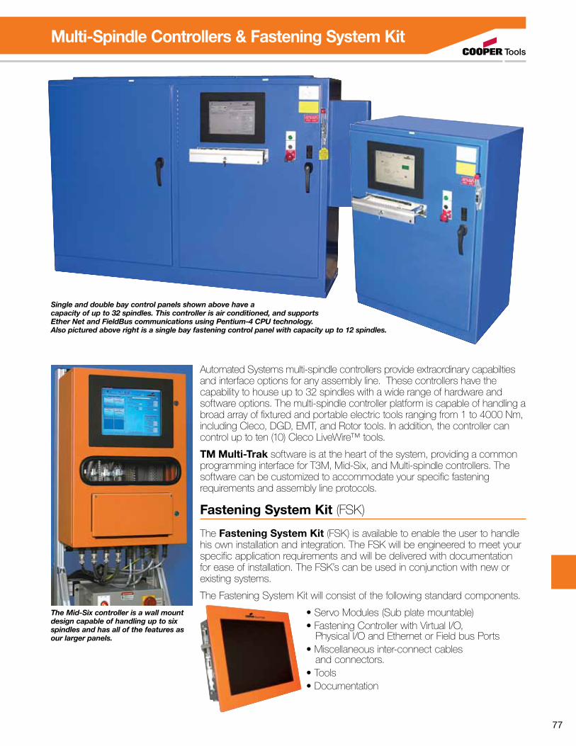
77
Multi-Spindle Controllers & Fastening System Kit
Single and double bay control panels shown above have a capacity of up to 32 spindles. This controller is air conditioned, and supports Ether Net and FieldBus communications using Pentium-4 CPU technology. Also pictured above right is a single bay fastening control panel with capacity up to 12 spindles.
Automated Systems multi-spindle controllers provide extraordinary capabilties and interface options for any assembly line. These controllers have the capability to house up to 32 spindles with a wide range of hardware and software options. The multi-spindle controller platform is capable of handling a broad array of fixtured and portable electric tools ranging from 1 to 4000 Nm, including Cleco, DGD, EMT, and Rotor tools. In addition, the controller can control up to ten (10) Cleco LiveWire™ tools.
TM Multi-Trak software is at the heart of the system, providing a common programming interface for T3M, Mid-Six, and Multi-spindle controllers. The software can be customized to accommodate your specific fastening requirements and assembly line protocols.
Fastening System Kit (FSK)
The Fastening System Kit (FSK) is available to enable the user to handle his own installation and integration. The FSK will be engineered to meet your specific application requirements and will be delivered with documentation for ease of installation. The FSK’s can be used in conjunction with new or existing systems.
The Fastening System Kit will consist of the following standard components.
• Servo Modules (Sub plate mountable)• Fastening Controller with Virtual I/O, Physical I/O and Ethernet or Field bus Ports• Miscellaneous inter-connect cables and connectors. • Tools• Documentation
The Mid-Six controller is a wall mount design capable of handling up to six spindles and has all of the features as our larger panels.
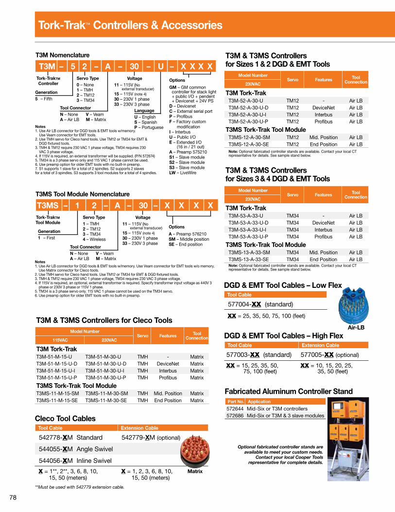
78
Tork-Trak™ Controllers & Accessories
Optional fabricated controller stands are available to meet your custom needs.
Contact your local Cooper Tools representative for complete details.
Servo Type1 – TMH2 – TM123 – TM344 – Wireless
T3MS – 1 2 – A – 30 – X X X XT3MS Tool Module Nomenclature
Generation1 – First
Voltage11 – 115V (No external transducer)15 – 115V (note 4)30 – 230V 1 phase33 – 230V 3 phase
Tork-TrakTM Tool Module
Tool ConnectorN – None V – VeamA – Air LB M – Matrix
Notes1. Use Air LB connector for DGD tools & EMT tools w/memory. Use Veam connector for EMT tools w/o memory. Use Matrix connector for Cleco tools.2. Use TMH servo for Cleco hand tools. Use TM12 or TM34 for EMT & DGD fixtured tools.3. TMH & TM12 require 230 VAC 1 phase voltage, TM34 requires 230 VAC 3 phase voltage.4. If 115V is required, an optional, external transformer is required. Specify transformer input voltage as 440V 3 phase or 230V 3 phase or 115V 1 phase.5. TM34 is a 3 phase servo only. 115 VAC 1 phase cannot be used on the TM34 servo.6. Use preamp option for older EMT tools with no built-in preamp.
Options
A – Preamp 576210SM – Middle positionSE – End position
Model NumberServo Features Tool
Connection115VAC 230VAC
T3M Tork-TrakT3M-51-M-15-U T3M-51-M-30-U TMH - MatrixT3M-51-M-15-U-D T3M-51-M-30-U-D TMH DeviceNet MatrixT3M-51-M-15-U-I T3M-51-M-30-U-I TMH Interbus MatrixT3M-51-M-15-U-P T3M-51-M-30-U-P TMH Profibus Matrix
T3MS Tork-Trak Tool ModuleT3MS-11-M-15-SM T3MS-11-M-30-SM TMH Mid. Position MatrixT3MS-11-M-15-SE T3MS-11-M-30-SE TMH End Position Matrix
T3M & T3MS Controllers for Cleco Tools
Cleco Tool Cables Tool Cable Extension Cable
542778-XM Standard 542779-XM (optional)
544055-XM Angle Swivel
544056-XM Inline Swivel
X = 1**, 2**, 3, 6, 8, 10, 15, 50 (meters)
X = 1, 2, 3, 6, 8, 10, 15, 50 (meters)
**Must be used with 542779 extension cable.
Matrix
T3M & T3MS Controllers for Sizes 1 & 2 DGD & EMT Tools
Model NumberServo Features Tool
Connection230VAC
T3M Tork-TrakT3M-52-A-30-U TM12 - Air LBT3M-52-A-30-U-D TM12 DeviceNet Air LBT3M-52-A-30-U-I TM12 Interbus Air LBT3M-52-A-30-U-P TM12 Profibus Air LB
T3MS Tork-Trak Tool ModuleT3MS-12-A-30-SM TM12 Mid. Position Air LBT3MS-12-A-30-SE TM12 End Position Air LB Note: Optional fabricated controller stands are available. Contact your local CT representative for details. See sample stand below.
DGD & EMT Tool Cables – High Flex Tool Cable Extension Cable
577003-XX (standard) 577005-XX (optional)
XX = 15, 25, 35, 50, 75, 100 (feet)
XX = 10, 15, 20, 25, 35, 50 (feet)
Fabricated Aluminum Controller Stand Part No. Application
572644 Mid-Six or T3M controllers 572686 Mid-Six or T3M & 3 slave modules
DGD & EMT Tool Cables – Low Flex Tool Cable
577004-XX (standard)
XX = 25, 35, 50, 75, 100 (feet)
Air-LB
Model NumberServo Features Tool
Connection230VAC
T3M Tork-TrakT3M-53-A-33-U TM34 - Air LBT3M-53-A-33-U-D TM34 DeviceNet Air LBT3M-53-A-33-U-I TM34 Interbus Air LBT3M-53-A-33-U-P TM34 Profibus Air LB
T3MS Tork-Trak Tool ModuleT3MS-13-A-33-SM TM34 Mid. Position Air LBT3MS-13-A-33-SE TM34 End Position Air LB Note: Optional fabricated controller stands are available. Contact your local CT representative for details. See sample stand below.
T3M & T3MS Controllers for Sizes 3 & 4 DGD & EMT Tools
Servo Type0 – None1 – TMH2 – TM123 – TM34
T3M – 5 2 – A – 30 – U – X X X X
LanguageU – EnglishS – SpanishP – Portuguese
T3M Nomenclature
Generation5 – Fifth
Voltage11 – 115V (No external transducer)15 – 115V (note 4)30 – 230V 1 phase33 – 230V 3 phase
Tork-TrakTM Controller
Tool ConnectorN – None V – VeamA – Air LB M – Matrix
Options
GM – GM common controller for stack light + public I/O + pendent + Devicenet + 24V PSD – DevicenetC – External serial portP – ProfibusF – Factory custom modificationI – InterbusU – Public I/OE – Extended I/O (16 in / 21 out)A – Preamp 575210S1 – Slave moduleS2 – Slave moduleS3 – Slave moduleLW – LiveWire
Notes1. Use Air LB connector for DGD tools & EMT tools w/memory. Use Veam connector for EMT tools.2. Use TMH servo for Cleco hand tools. Use TM12 or TM34 for EMT & DGD fixtured tools.3. TMH & TM12 require 230 VAC 1 phase voltage, TM34 requires 230 VAC 3 phase voltage.4. If 115V is required, an external transformer will be supplied. (P/N 572674)5. TM34 is a 3 phase servo only and 115 VAC 1 phase cannot be used.6. Use preamp option for older EMT tools with no built-in preamp.7. S1 supports 1 slave for a total of 2 spindles. S2 supports 2 slaves for a total of 3 spindles. S3 supports 3 tool modules for a total of 4 spindles.
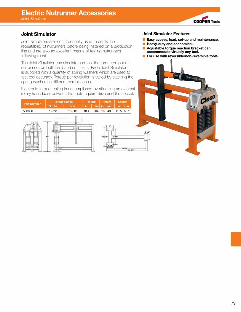
79
Electric Nutrunner AccessoriesJoint Simulator
Joint SimulatorJoint simulators are most frequently used to certify the repeatability of nutrunners before being installed on a production line and are also an excellent means of testing nutrunners following repair.
The Joint Simulator can simulate and test the torque output of nutrunners on both hard and soft joints. Each Joint Simulator is supplied with a quantity of spring washers which are used to test tool accuracy. Torque per revolution is varied by stacking the spring washers in different combinations.
Electronic torque testing is accomplished by attaching an external rotary transducer between the tool’s square drive and the socket.
Part Number
Torque Range Width Height Length
Ft. Lbs. Nm in. mm in. mm in. mm
550006 12-220 15-300 10.4 264 16 406 26.5 667
Joint Simulator Features■ Easy access, load, set-up and maintenance.■ Heavy-duty and economical.■ Adjustable torque reaction bracket can accommodate virtually any tool.■ For use with reversible/non-reversible tools.
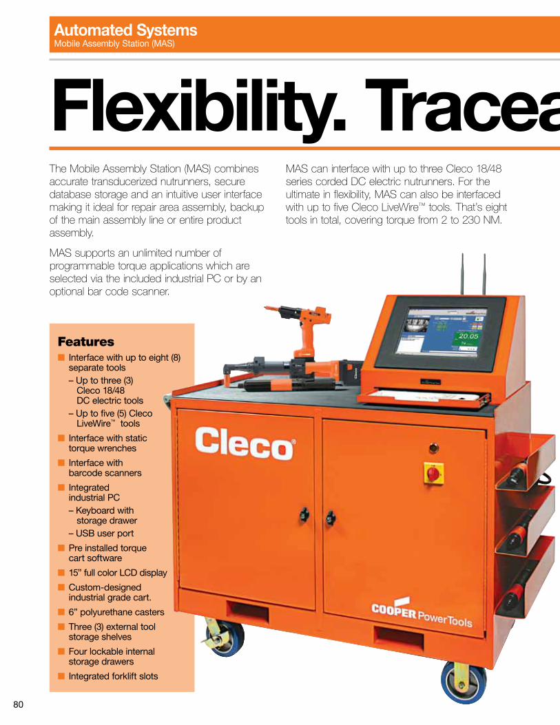
80
The Mobile Assembly Station (MAS) combines accurate transducerized nutrunners, secure database storage and an intuitive user interface making it ideal for repair area assembly, backup of the main assembly line or entire product assembly.
MAS supports an unlimited number of programmable torque applications which are selected via the included industrial PC or by an optional bar code scanner.
MAS can interface with up to three Cleco 18/48 series corded DC electric nutrunners. For the ultimate in flexibility, MAS can also be interfaced with up to five Cleco LiveWire™ tools. That’s eight tools in total, covering torque from 2 to 230 NM.
Features■ Interface with up to eight (8) separate tools – Up to three (3) Cleco 18/48 DC electric tools – Up to five (5) Cleco LiveWire™ tools
■ Interface with static torque wrenches
■ Interface with barcode scanners
■ Integrated industrial PC – Keyboard with storage drawer – USB user port
■ Pre installed torque cart software
■ 15” full color LCD display
■ Custom-designed industrial grade cart.
■ 6” polyurethane casters
■ Three (3) external tool storage shelves
■ Four lockable internal storage drawers
■ Integrated forklift slots
Flexibility. Traceability. Portability. Automated SystemsMobile Assembly Station (MAS)
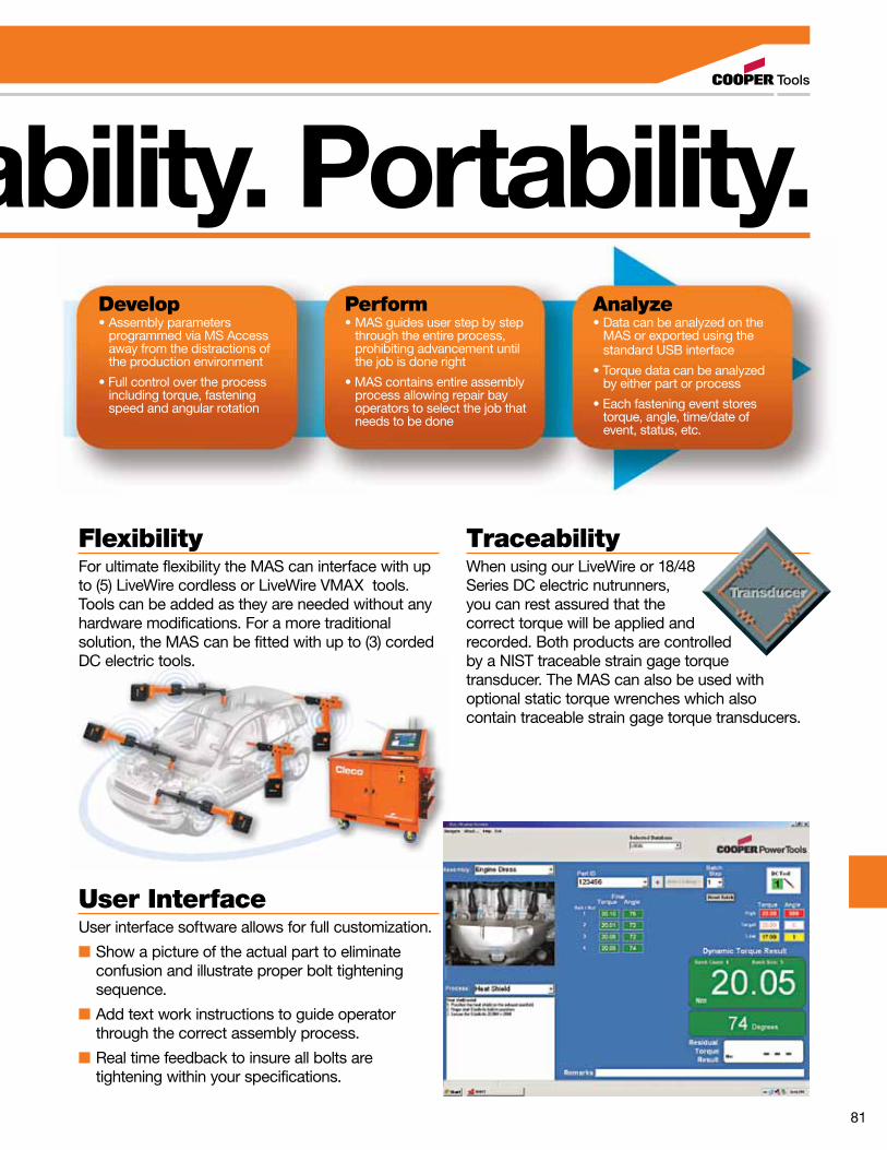
81
FlexibilityFor ultimate flexibility the MAS can interface with up to (5) LiveWire cordless or LiveWire VMAX tools. Tools can be added as they are needed without any hardware modifications. For a more traditional solution, the MAS can be fitted with up to (3) corded DC electric tools.
Develop•Assemblyparameters programmed via MS Access away from the distractions of the production environment
•Fullcontrolovertheprocess including torque, fastening speed and angular rotation
Perform•MASguidesuserstepbystep through the entire process, prohibiting advancement until the job is done right
•MAScontainsentireassembly process allowing repair bay operators to select the job that needs to be done
Analyze•Datacanbeanalyzedonthe MAS or exported using the standard USB interface
•Torquedatacanbeanalyzed by either part or process
•Eachfasteningeventstores torque, angle, time/date of event, status, etc.
User InterfaceUser interface software allows for full customization.
■ Show a picture of the actual part to eliminate confusion and illustrate proper bolt tightening sequence.
■ Add text work instructions to guide operator through the correct assembly process.
■ Real time feedback to insure all bolts are tightening within your specifications.
TraceabilityWhen using our LiveWire or 18/48 Series DC electric nutrunners, you can rest assured that the correct torque will be applied and recorded. Both products are controlled by a NIST traceable strain gage torque transducer. The MAS can also be used with optional static torque wrenches which also contain traceable strain gage torque transducers.
Flexibility. Traceability. Portability.
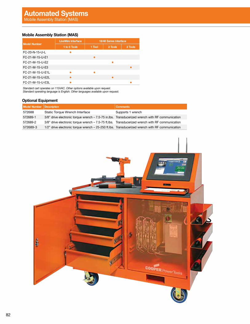
82
Automated Systems Mobile Assembly Station (MAS)
Model NumberLiveWire Interface 18/48 Series Interface
1 to 5 Tools 1 Tool 2 Tools 3 Tools
FC-20-N-15-U-L •FC-21-M-15-U-E1 •FC-21-M-15-U-E2 •FC-21-M-15-U-E3 •FC-21-M-15-U-E1L • •FC-21-M-15-U-E2L • •FC-21-M-15-U-E3L • •Standard cart operates on 115VAC. Other options available upon request.Standard operating language is English. Other languages available upon request.
Mobile Assembly Station (MAS)
Model Number Description Comments
572688 Static Torque Wrench Interface Supports 1 wrench
572689-1 3/8” drive electronic torque wrench – 7.5-75 in.lbs. Transducerized wrench with RF communication
572689-2 3/8” drive electronic torque wrench – 7.5-75 ft.lbs. Transducerized wrench with RF communication
572689-3 1/2” drive electronic torque wrench – 25-250 ft.lbs. Transducerized wrench with RF communication
Optional Equipment
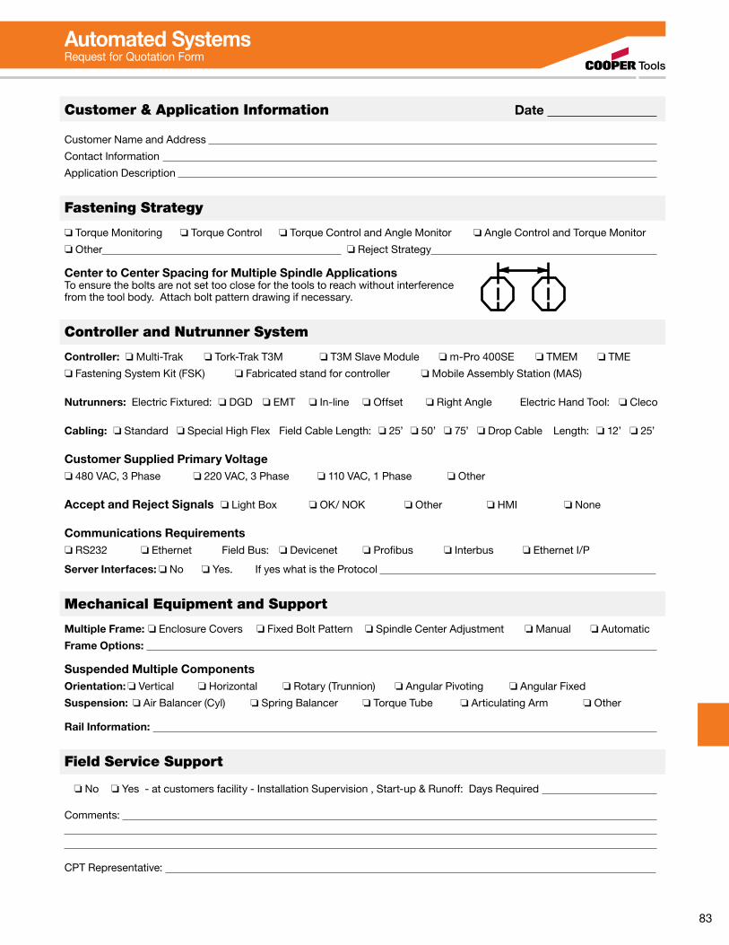
83
Automated Systems Request for Quotation Form
Customer & Application Information Date
Customer Name and Address
Contact Information
Application Description
Fastening Strategy
o Torque Monitoring o Torque Control o Torque Control and Angle Monitor o Angle Control and Torque Monitor
o Other o Reject Strategy
Center to Center Spacing for Multiple Spindle ApplicationsTo ensure the bolts are not set too close for the tools to reach without interference from the tool body. Attach bolt pattern drawing if necessary.
Controller and Nutrunner System
Controller: o Multi-Trak o Tork-Trak T3M o T3M Slave Module o m-Pro 400SE o TMEM o TME
o Fastening System Kit (FSK) o Fabricated stand for controller o Mobile Assembly Station (MAS)
Nutrunners: Electric Fixtured: o DGD o EMT o In-line o Offset o Right Angle Electric Hand Tool: o Cleco
Cabling: o Standard o Special High Flex Field Cable Length: o 25’ o 50’ o 75’ o Drop Cable Length: o 12’ o 25’
Customer Supplied Primary Voltageo 480 VAC, 3 Phase o 220 VAC, 3 Phase o 110 VAC, 1 Phase o Other
Accept and Reject Signals o Light Box o OK/ NOK o Other o HMI o None
Communications Requirementso RS232 o Ethernet Field Bus: o Devicenet o Profibus o Interbus o Ethernet I/P
Server Interfaces: o No o Yes. If yes what is the Protocol
Mechanical Equipment and Support
Multiple Frame: o Enclosure Covers o Fixed Bolt Pattern o Spindle Center Adjustment o Manual o Automatic
Frame Options:
Suspended Multiple ComponentsOrientation: o Vertical o Horizontal o Rotary (Trunnion) o Angular Pivoting o Angular Fixed
Suspension: o Air Balancer (Cyl) o Spring Balancer o Torque Tube o Articulating Arm o Other
Rail Information:
Field Service Support
o No o Yes - at customers facility - Installation Supervision , Start-up & Runoff: Days Required
Comments:
CPT Representative:
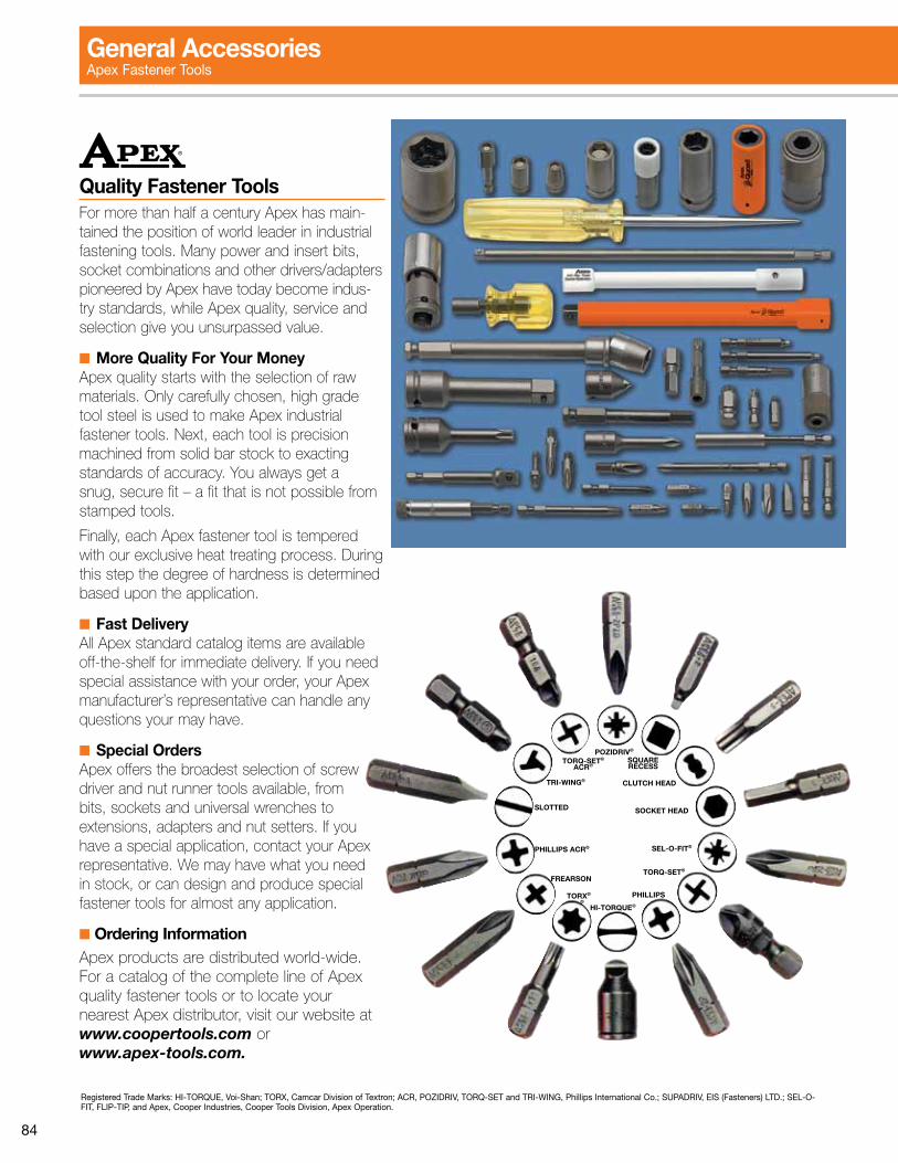
84
Quality Fastener ToolsFor more than half a century Apex has main-tained the position of world leader in industrial fastening tools. Many power and insert bits, socket combinations and other drivers/adapters pioneered by Apex have today become indus-try standards, while Apex quality, service and selection give you unsurpassed value.
■ More Quality For Your MoneyApex quality starts with the selection of raw materials. Only carefully chosen, high grade tool steel is used to make Apex industrial fastener tools. Next, each tool is precision machined from solid bar stock to exacting standards of accuracy. You always get a snug, secure fit – a fit that is not possible from stamped tools.
Finally, each Apex fastener tool is tempered with our exclusive heat treating process. During this step the degree of hardness is determined based upon the application.
■ Fast DeliveryAll Apex standard catalog items are available off-the-shelf for immediate delivery. If you need special assistance with your order, your Apex manufacturer’s representative can handle any questions your may have.
■ Special OrdersApex offers the broadest selection of screw driver and nut runner tools available, from bits, sockets and universal wrenches to extensions, adapters and nut setters. If you have a special application, contact your Apex representative. We may have what you need in stock, or can design and produce special fastener tools for almost any application.
■ Ordering InformationApex products are distributed world-wide. For a catalog of the complete line of Apex quality fastener tools or to locate your nearest Apex distributor, visit our website at www.coopertools.com or www.apex-tools.com.
Registered Trade Marks: HI-TORQUE, Voi-Shan; TORX, Camcar Division of Textron; ACR, POZIDRIV, TORQ-SET and TRI-WING, Phillips International Co.; SUPADRIV, EIS (Fasteners) LTD.; SEL-O-FIT, FLIP-TIP, and Apex, Cooper Industries, Cooper Tools Division, Apex Operation.
POZIDRIV®
TORQ-SET®
ACR®
TORQ-SET®
SEL-O-FIT®
SOCKET HEAD
CLUTCH HEAD
SQUARE RECESS
PHILLIPS ACR®
TORX®
HI-TORQUE®
PHILLIPS®
FREARSON
TRI-WING®
SLOTTED
General AccessoriesApex Fastener Tools
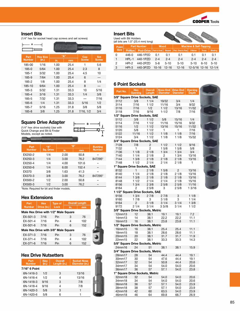
85
Insert Bits(1/4” hex for socket head cap screws and set screws)
A
Insert BitsUsed with Bit Holders (all bits are 1.0” (25.4 mm) long)
PartNumber
Hex Size(in.)
“A” CapScrew
SetScrewin. mm
185-00 1/16 1.00 25.4 1 5.6185-0 5/64 1.00 25.4 2.3 8185-1 3/32 1.00 25.4 4.5 10185-9 7/64 1.00 25.4 6 —185-2 1/8 1.00 25.4 8 1/4185-10 9/64 1.00 25.4 8 —185-3 5/32 1.31 33.3 10 5/16185-4 3/16 1.31 33.3 1/4 3/8185-5 7/32 1.31 33.3 — 7/16185-6 1/4 1.31 33.3 5/16 1/2185-7 5/16 1.25 31.8 3/8 5/8185-8 3/8 1.25 31.8 7/16, 1/2 3/4
Square Drive Adapter(1/4” hex drive sockets) Use with Quick Change and Bit & Finder Models, except as noted.
B
A
PartNumber
“A”Sq. Drive
“B” BushingNumberin. mm
EX250-2 1/4 2.00 50.8 –EX250-3 1/4 3.00 76.2 847295*EX250-4 1/4 4.00 101.6 –EX250-6 1/4 6.00 152.4 –EX370 3/8 1.63 41.3 –EX370-3 3/8 3.00 76.2 847295*EX500-2 1/2 2.00 50.8 –EX500-3 1/2 3.00 76.2 –
*Note: Required for bit and finder models.
Hex ExtensionsPart
NumberHex
Drive (in.)Type ofLock
Overall Length
in. mm
Male Hex Drive with 1/2” Male Square
EX-501-3 7/16 Pin 3 76EX-501-4 7/16 Pin 4 102EX-501-6 7/16 Pin 6 152
Male Hex Drive with 3/8” Male Square
EX-371-3 7/16 Pin 3 76EX-371-4 7/16 Pin 4 102EX-371-6 7/16 Pin 6 152
Hex Drive NutsettersPart
NumberSize(in.)
OverallLength (in.)
Socket NoseDiameter (in.)
7/16” 6 Point
6N-1416-3 1/2 3 13/166N-1416-4 1/2 4 13/166N-1418-3 9/16 3 7/86N-1418-4 9/16 4 7/86N-1420-3 5/8 3 16N-1420-6 5/8 6 1
PointSize
Part Number Wood Machine & Self-Tapping
Phillips Pozi-Drive Flat & Oval Round Flat, Oval & Pan Fillister Truss Binding
0 446-0 446-1P2D 0.1 0.1 0.1 0.1 0.1 0.11 HPL-1 440-1PZD 2-4 2-4 2-4 2-4 2-4 2-42 HPI-2 440-2PZD 5-8 5-10 5-10 5-10 6-10 5-103 HPI-3 440-3PZD 10-16 12-16 12-16 12-5/16 12-16 12-1/4
6 Point SocketsPart No. Hex
OpeningOverallLength
Nose EndDiameter
Drive EndDiameter
OpeningDepth
3/8” Square Drive Sockets, SAE3112 3/8 1 1/4 19/32 3/4 1/43114 7/16 1 1/2 11/16 3/4 9/323116 7/16 1/2 1 1/2 13/16 11/323118 7/16 9/16 1-1/2 7/8 7/16
1/2” Square Drive Sockets, SAE5112 3/8 1 1/2 5/8 15/16 1/45114 7/16 1 1/2 11/16 15/16 9/325116 1/2 1 1/2 13/16 15/16 11/325120 5/8 1 1/2 1 1 7/165122 11/16 1 1/2 1 1/8 1 1/8 7/165124 3/4 1 1/2 1 1/8 1 1/8 15/32
3/4” Square Drive Sockets, SAE7128 7/8 2 1 1/2 1 1/2 9/167132 1 2 1 5/8 1 5/8 5/87136 1 1/8 2 1/8 1 3/4 1 3/4 3/47140 1 1/4 2 1/8 2 1 3/4 13/167144 1 3/8 2 1/8 2 1/8 2 1/8 13/167148 1 1/2 2 1/4 2 1/4 2 1/8 1
1” Square Drive Sockets, SAE8132 1 2 1/8 1 5/8 2 13/168140 1 1/4 2 1/8 2 1/8 2 1/8 13/168144 1 3/8 2 1/8 2 1/8 2 1/8 13/168148 1 1/2 2 1/4 2 1/4 2 1/8 15/168156 1 3/4 2 3/8 2 5/8 2 5/8 11/168164 2 2 5/8 3 2 5/8 1 3/16
1 1/2” Square Drive Sockets, SAE9156 1 3/4 2 7/8 2 7/8 3 1 1/89160 1 7/8 3 3 1/8 3 1 1/49164 2 3 1/8 3 1/4 3 1/4 1 3/89172 2 1/4 3 1/4 3 3//8 3 1/4 1 1/2
3/8” Square Drive Sockets, Metric12mm13 12 38.1 19.1 19.1 7.214mm13 14 38.1 22.2 22.2 11.116mm13 16 38.1 23.8 23.8 11.1
1/2” Square Drive Sockets, Metric16mm15 16 38.1 25.4 25.4 11.118mm15 18 38.1 28.6 28.6 11.120mm15 20 38.1 31.7 31.7 11.922mm15 22 38.1 33.3 33.3 14.3
5/8” Square Drive Sockets, Metric24mm16 24 51 38.1 38.1 15.9
3/4” Square Drive Sockets, Metric28mm17 28 54 44.4 44.4 19.130mm17 30 54 47.6 44.4 19.132mm17 32 54 50.8 44.4 20.634mm17 34 54 54.0 54.0 20.636mm17 36 57 57.1 54.0 23.8
1” Square Drive Sockets, Metric32mm18 32 54 54.0 54.0 20.634mm18 34 54 54.0 54.0 20.636mm18 36 57 57.1 54.0 23.938mm18 38 57 57.1 54.0 23.942mm18 42 60 63.5 54.0 23.946mm18 46 64 69.8 66.7 26.9

86
Quality Anti-Mar Fastener Tools Begin With Quality Fastener Tools.
Apex µ-Guard™ provides a protective barrier between genuine Apex fastener tools and your finely finished workpiece. The free-spinning patent-pending design provides maximum protection for polished and highly sensitive surfaces.
Apex µ-Guard™ covering is made of a thermo plastic urethane (TPU elastomer) which cushions against costly incidental side impacts. It offers the lowest coefficient of friction for maximum tool efficiency. It is also non-removable for tamper resistance.
With Apex µ-Guard™ you get the proven Apex fastener tool fit and performance plus the best protection available against marring and in-system damage.
µ-Guard™ is your guard against the potential hazards caused by rotational friction.
Prevents Side Impact Damage
Free-Spinning Design
Virtually Damage Free
If it doesn’t say Apex on the outside, how can
you be sure of what’s on the inside?
General AccessoriesApex µ-Guard
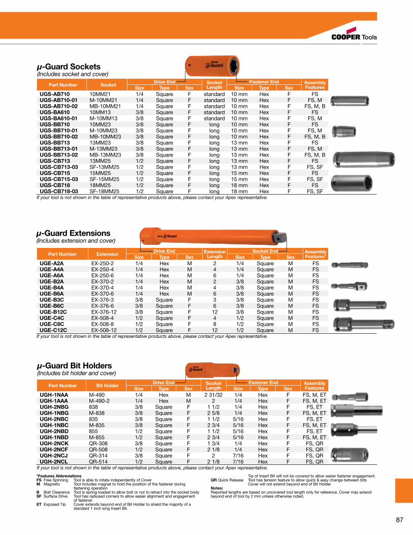
87
µ-Guard Sockets(Includes socket and cover)
Part Number SocketDrive End Socket
LengthFastener End Assembly
FeaturesSize Type Sex Size Type SexUGS-AB710 10MM21 1/4 Square F standard 10 mm Hex F FSUGS-AB710-01 M-10MM21 1/4 Square F standard 10 mm Hex F FS, MUGS-AB710-02 MB-10MM21 1/4 Square F standard 10 mm Hex F FS, M, BUGS-BA610 10MM13 3/8 Square F standard 10 mm Hex F FSUGS-BA610-01 M-10MM13 3/8 Square F standard 10 mm Hex F FS, MUGS-BB710 10MM23 3/8 Square F long 10 mm Hex F FSUGS-BB710-01 M-10MM23 3/8 Square F long 10 mm Hex F FS, MUGS-BB710-02 MB-10MM23 3/8 Square F long 10 mm Hex F FS, M, BUGS-BB713 13MM23 3/8 Square F long 13 mm Hex F FSUGS-BB713-01 M-13MM23 3/8 Square F long 13 mm Hex F FS, MUGS-BB713-02 MB-13MM23 3/8 Square F long 13 mm Hex F FS, M, BUGS-CB713 13MM25 1/2 Square F long 13 mm Hex F FSUGS-CB713-03 SF-13MM25 1/2 Square F long 13 mm Hex F FS, SFUGS-CB715 15MM25 1/2 Square F long 15 mm Hex F FSUGS-CB715-03 SF-15MM25 1/2 Square F long 15 mm Hex F FS, SFUGS-CB718 18MM25 1/2 Square F long 18 mm Hex F FSUGS-CB718-03 SF-18MM25 1/2 Square F long 18 mm Hex F FS, SF
If your tool is not shown in the table of representative products above, please contact your Apex representative.
Part Number ExtensionDrive End Extension
LengthSocket End Assembly
Features*Size Type Sex Size Type SexUGE-A2A EX-250-2 1/4 Hex M 2 1/4 Square M FSUGE-A4A EX-250-4 1/4 Hex M 4 1/4 Square M FSUGE-A6A EX-250-6 1/4 Hex M 6 1/4 Square M FSUGE-B2A EX-370-2 1/4 Hex M 2 3/8 Square M FSUGE-B4A EX-370-4 1/4 Hex M 4 3/8 Square M FSUGE-B6A EX-370-6 1/4 Hex M 6 3/8 Square M FSUGE-B3C EX-376-3 3/8 Square F 3 3/8 Square M FSUGE-B6C EX-376-6 3/8 Square F 6 3/8 Square M FSUGE-B12C EX-376-12 3/8 Square F 12 3/8 Square M FSUGE-C4C EX-508-4 1/2 Square F 4 1/2 Square M FSUGE-C8C EX-508-8 1/2 Square F 8 1/2 Square M FSUGE-C12C EX-508-12 1/2 Square F 12 1/2 Square M FS
If your tool is not shown in the table of representative products above, please contact your Apex representative.
µ-Guard Extensions(Includes extension and cover)
*Features AbbreviationsFS Free Spinning Tool is able to rotate independently of CoverM Magnetic Tool includes magnet to hold the position of the fastener during fastening operationB Bolt Clearance Tool is spring-loaded to allow bolt or nut to retract into the socket bodySF Surface Drive Tool has radiused corners to allow easier alignment and engagement of fastenerET Exposed Tip Cover extends beyond end of Bit Holder to shield the majority of a standard 1 inch long Insert Bit.
Tip of Insert Bit will not be covered to allow easier fastener engagement.QR Quick Release Tool has tension feature to allow quick & easy change between bits Cover will not extend beyond end of Bit HolderNotes:Reported lengths are based on uncovered tool length only for reference. Cover may extend beyond end of tool by 2 mm unless otherwise noted.
µ-Guard Bit Holders(Includes bit holder and cover)
Part Number Bit HolderDrive End Socket
LengthFastener End Assembly
FeaturesSize Type Sex Size Type SexUGH-1NAA M-490 1/4 Hex M 2 31/32 1/4 Hex F FS, M, ETUGH-1AAA M-490-2 1/4 Hex M 2 1/4 Hex F FS, M, ETUGH-2NBG 838 3/8 Square F 1 1/2 1/4 Hex F FS, ETUGH-1NBG M-838 3/8 Square F 2 5/8 1/4 Hex F FS, M, ETUGH-2NBC 835 3/8 Square F 1 1/2 5/16 Hex F FS, ETUGH-1NBC M-835 3/8 Square F 2 3/4 5/16 Hex F FS, M, ETUGH-2NBD 855 1/2 Square F 1 1/2 5/16 Hex F FS, ETUGH-1NBD M-855 1/2 Square F 2 3/4 5/16 Hex F FS, M, ETUGH-2NCK QR-308 3/8 Square F 1 3/4 1/4 Hex F FS, QRUGH-2NCF QR-508 1/2 Square F 2 1/8 1/4 Hex F FS, QRUGH-2NCJ QR-314 3/8 Square F 2 7/16 Hex F FS, QRUGH-2NCL QR-514 1/2 Square F 2 1/8 7/16 Hex F FS, QR
If your tool is not shown in the table of representative products above, please contact your Apex representative.
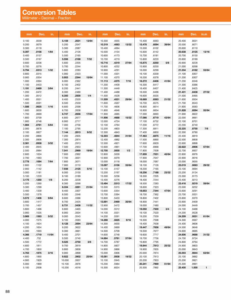
88
0.100 .0039
0.200 .0079
0.300 .0118
0.397 .0156 1/640.400 .0157
0.500 .0197
0.600 .0236
0.700 .0276
0.794 .0313 1/320.800 .0315
0.900 .0354
1.000 .0394
1.100 .0433
1.191 .0469 3/641.200 .0472
1.300 .0512
1.400 .0551
1.500 .0591
1.588 .0625 1/161.600 .0630
1.700 .0669
1.800 .0709
1.900 .0748
1.984 .0781 5/642.000 .0878
2.100 .0827
2.200 .0866
2.300 .0906
2.381 .0938 3/322.400 .0945
2.500 .0984
2.600 .1024
2.700 .1063
2.778 .1094 7/642.800 .1102
2.900 .1142
3.000 .1181
3.100 .1220
3.175 .1250 1/83.200 .1260
3.300 .1299
3.400 .1339
3.500 .1378
3.572 .1406 9/643.600 .1417
3.700 .1457
3.800 .1496
3.900 .1535
3.969 .1563 5/324.000 .1575
4.100 .1624
4.200 .1654
4.300 .1693
4.366 .1719 11/644.400 .732
4.500 .1772
4.600 .1811
4.700 .1850
4.763 .1875 3/164.800 .1890
4.900 .1929
5.000 .1969
5.100 .2008
5.159 .2031 13/645.200 .2047
5.300 .2087
5.400 .2126
5.500 .2165
5.556 .2188 7/325.600 .2205
5.700 .2244
5.800 .2283
5.900 .2323
5.953 .2344 15/646.000 .2362
6.100 .2402
6.200 .2441
6.300 .2480
6.350 .2500 1/46.400 .2520
6.500 .2559
6.600 .2598
6.700 .2638
6.747 .2656 17/646.800 .2677
6.900 .2717
7.000 .2756
7.100 .2795
7.144 .2813 9/327.200 .2835
7.300 .2874
7.400 .2913
7.500 .2953
7.541 .2969 19/647.600 .2992
7.700 .3031
7.800 .3071
7.900 .3110
7.938 .3125 5/168.000 .3150
8.100 .3189
8.200 .3228
8.300 .3268
8.334 .3281 21/648.400 .3307
8.500 .3346
8.600 .3386
8.700 .3425
8.731 .3438 11/328.800 .3465
8.900 .3504
9.000 .3543
9.100 .3583
9.128 .3594 23/649.200 .3622
9.300 .3661
9.400 .3701
9.500 .3740
9.525 .3750 3/8 9.700 .3819
9.800 .3858
9.900 .3898
9.922 .3902 25/6410.000 .3937
10.100 .3976
10.200 .4016
10.300 .4055
10.319 .4063 13/3210.400 .4094
10.500 .4134
10.600 .4173
10.700 .4219
10.716 .4219 27/6410.800 .4252
10.900 .4291
11.000 .4331
11.100 .4370
11.113 .4375 7/1611.200 .4409
11.300 .4449
11.400 .4488
11.500 .4528
11.509 .4531 29/6411.600 .4567
11.700 .4606
11.800 .4646
11.900 .4685
11.906 .4688 15/3212.000 .4724
12.100 .4764
12.200 .4803
12.300 .4843
12.303 .4844 31/6412.400 .4882
12.500 .4921
12.600 .4961
12.700 .5000 1/212.800 .5039
12.900 .5079
13.000 .5118
13.097 .5156 33/6413.100 .5157
13.200 .5197
13.300 .5236
13.400 .5276
13.494 .5313 17/3213.500 .5315
13.600 .5354
13.700 .5394
13.800 .5433
13.891 .5469 35/6413.900 .5472
14.000 .5512
14.100 .5551
14.200 .5591
14.288 .5625 9/1614.300 .5630
14.400 .5669
14.500 .5709
14.600 .5748
14.684 .5781 37/6414.700 .5787
14.800 .5827
14.900 .5866
15.000 .5906
15.081 .5938 19/3215.100 .5945
15.200 .5984
15.300 .6024
15.400 .6063
15.478 .6094 39/6415.500 .6102
15.600 .6142
15.700 .6181
15.800 .6220
15.875 .6250 5/815.900 .6250
16.000 .6299
16.100 .6339
16.200 .6378
16.272 .6406 41/6416.300 .6417
16.400 .6457
16.500 .6496
16.600 .6535
16.669 .6563 21/3216.700 .6575
16.800 .6614
16.900 .6654
17.000 .6693
17.066 .6719 43/6417.100 .6732
17.200 .6772
17.300 .6811
17.400 .6850
17.463 .6875 11/1617.500 .6890
17.600 .6929
17.700 .6968
17.800 .7008
17.859 .7031 45/6417.900 .7047
18.000 .7087
18.100 .7126
18.200 .7165
18.256 .7188 23/3218.300 .7205
18.400 .7244
18.500 .7283
18.600 .7323
18.653 .7344 47/6418.700 .7362
18.800 .7402
18.900 .7441
19.000 .7480
19.050 .7500 3/419.100 .7520
19.200 .7559
19.300 .7598
19.400 .7638
19.447 .7656 49/6419.500 .7677
19.600 .7717
19.700 .7756
19.800 .7795
19.844 .7813 25/3219.900 .7835
20.000 .7874
20.100 .7913
20.200 .7953
20.241 .7969 51/6420.300 .7992
20.400 .8031
20.500 .8071
20.600 .8110
20.638 .8125 13/1620.700 .8150
20.800 .8189
20.900 .8228
21.000 .8268
21.034 .8182 53/6421.100 .8307
21.200 .8307
21.200 .8346
21.300 .8386
21.400 .8425
21.431 .8438 27/3221.500 .8465
21.600 .8504
21.700 .8543
21.800 .8583
21.828 .8594 55/9421.900 .8622
22.000 .8661
22.100 .8701
22.200 .8740
22.225 .8750 7/822.300 .8780
22.400 .8819
22.500 .8858
22.600 .8898
22.622 .8906 57/6422.700 .8937
22.800 .8976
22.900 .9016
23.000 .9055
23.019 .9063 29/3223.100 .9094
23.200 .9134
23.300 .9173
23.400 .9213
23.416 .9219 59/6423.500 .9252
23.600 .9291
23.700 .9331
23.800 .9370
23.900 .9409
24.000 .9449
24.100 .9488
24.200 .9528
24.209 .9531 61/6424.300 .9567
24.400 .9606
24.500 .9646
24.600 .9685
24.606 .9688 31/3224.700 .9724
24.800 .9764
24.900 .9803
25.000 .9843
25.003 .9844 63/6425.100 .9882
25.200 .9921
25.300 .9961
25.400 1.000 1
mm Dec. in. mm Dec. in. mm Dec. in. mm Dec. in. mm Dec. in.m
Conversion TablesMillimeter – Decimal – Fraction
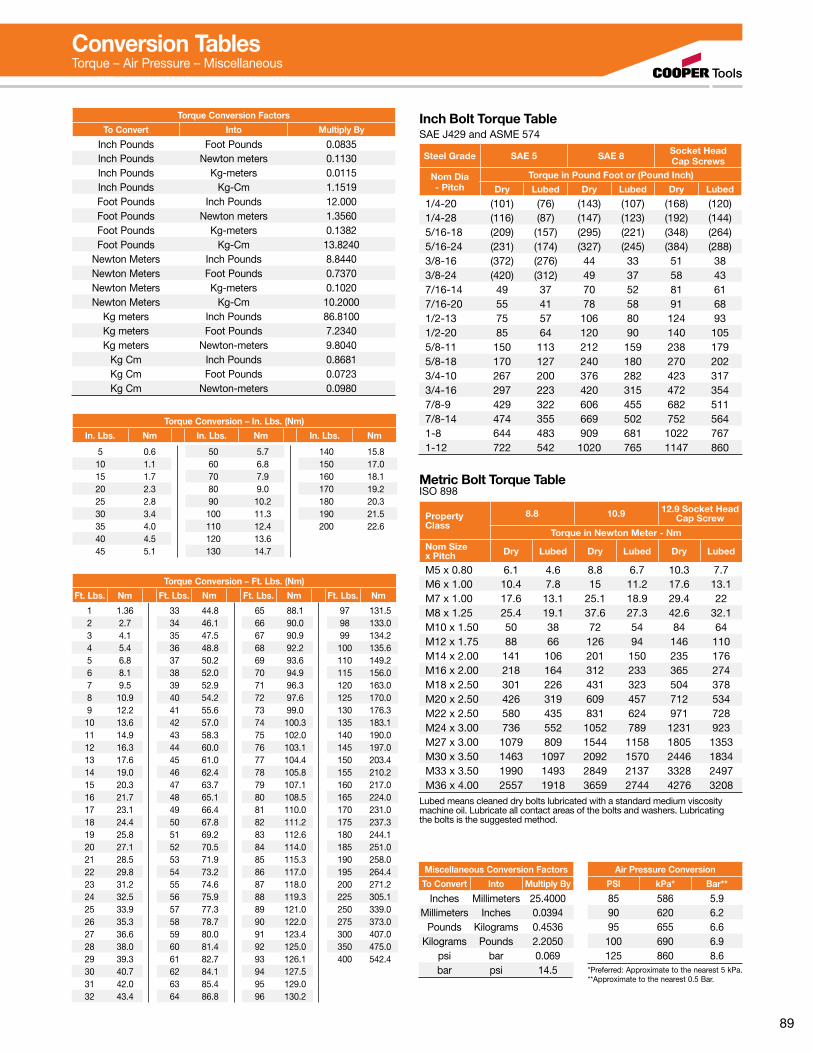
89
5 0.610 1.115 1.720 2.325 2.830 3.435 4.040 4.545 5.1
50 5.760 6.870 7.980 9.090 10.2100 11.3110 12.4120 13.6130 14.7
140 15.8150 17.0160 18.1170 19.2180 20.3190 21.5200 22.6
Torque Conversion – In. Lbs. (Nm)
In. Lbs. Nm In. Lbs. Nm In. Lbs. Nm
Torque Conversion Factors
To Convert Into Multiply By
Inch Pounds Foot Pounds 0.0835Inch Pounds Newton meters 0.1130Inch Pounds Kg-meters 0.0115Inch Pounds Kg-Cm 1.1519Foot Pounds Inch Pounds 12.000Foot Pounds Newton meters 1.3560Foot Pounds Kg-meters 0.1382Foot Pounds Kg-Cm 13.8240
Newton Meters Inch Pounds 8.8440Newton Meters Foot Pounds 0.7370Newton Meters Kg-meters 0.1020Newton Meters Kg-Cm 10.2000
Kg meters Inch Pounds 86.8100Kg meters Foot Pounds 7.2340Kg meters Newton-meters 9.8040
Kg Cm Inch Pounds 0.8681Kg Cm Foot Pounds 0.0723Kg Cm Newton-meters 0.0980
Inch Bolt Torque TableSAE J429 and ASME 574
Steel Grade SAE 5 SAE 8 Socket HeadCap Screws
Nom Dia - Pitch
Torque in Pound Foot or (Pound Inch)
Dry Lubed Dry Lubed Dry Lubed
1/4-20 (101) (76) (143) (107) (168) (120)1/4-28 (116) (87) (147) (123) (192) (144)5/16-18 (209) (157) (295) (221) (348) (264)5/16-24 (231) (174) (327) (245) (384) (288)3/8-16 (372) (276) 44 33 51 383/8-24 (420) (312) 49 37 58 437/16-14 49 37 70 52 81 617/16-20 55 41 78 58 91 681/2-13 75 57 106 80 124 931/2-20 85 64 120 90 140 1055/8-11 150 113 212 159 238 1795/8-18 170 127 240 180 270 2023/4-10 267 200 376 282 423 3173/4-16 297 223 420 315 472 3547/8-9 429 322 606 455 682 5117/8-14 474 355 669 502 752 5641-8 644 483 909 681 1022 7671-12 722 542 1020 765 1147 860
Metric Bolt Torque TableISO 898
PropertyClass
8.8 10.9 12.9 Socket HeadCap Screw
Torque in Newton Meter - NmNom Size x Pitch Dry Lubed Dry Lubed Dry Lubed
M5 x 0.80 6.1 4.6 8.8 6.7 10.3 7.7M6 x 1.00 10.4 7.8 15 11.2 17.6 13.1M7 x 1.00 17.6 13.1 25.1 18.9 29.4 22M8 x 1.25 25.4 19.1 37.6 27.3 42.6 32.1M10 x 1.50 50 38 72 54 84 64M12 x 1.75 88 66 126 94 146 110M14 x 2.00 141 106 201 150 235 176M16 x 2.00 218 164 312 233 365 274M18 x 2.50 301 226 431 323 504 378M20 x 2.50 426 319 609 457 712 534M22 x 2.50 580 435 831 624 971 728M24 x 3.00 736 552 1052 789 1231 923M27 x 3.00 1079 809 1544 1158 1805 1353M30 x 3.50 1463 1097 2092 1570 2446 1834M33 x 3.50 1990 1493 2849 2137 3328 2497M36 x 4.00 2557 1918 3659 2744 4276 3208
Lubed means cleaned dry bolts lubricated with a standard medium viscosity machine oil. Lubricate all contact areas of the bolts and washers. Lubricating the bolts is the suggested method.
Miscellaneous Conversion Factors
To Convert Into Multiply By
Inches Millimeters 25.4000Millimeters Inches 0.0394
Pounds Kilograms 0.4536Kilograms Pounds 2.2050
psi bar 0.069bar psi 14.5
Air Pressure Conversion
PSI kPa* Bar**
85 586 5.990 620 6.295 655 6.6100 690 6.9125 860 8.6
*Preferred: Approximate to the nearest 5 kPa.**Approximate to the nearest 0.5 Bar.
1 1.362 2.73 4.14 5.45 6.86 8.17 9.58 10.99 12.210 13.611 14.912 16.313 17.614 19.015 20.316 21.717 23.118 24.419 25.820 27.121 28.522 29.823 31.224 32.525 33.926 35.327 36.628 38.029 39.330 40.731 42.032 43.4
33 44.834 46.135 47.536 48.837 50.238 52.039 52.940 54.241 55.642 57.043 58.344 60.045 61.046 62.447 63.748 65.149 66.450 67.851 69.252 70.553 71.954 73.255 74.656 75.957 77.358 78.759 80.060 81.461 82.762 84.163 85.464 86.8
65 88.166 90.067 90.968 92.269 93.670 94.971 96.372 97.673 99.074 100.375 102.076 103.177 104.478 105.879 107.180 108.581 110.082 111.283 112.684 114.085 115.386 117.087 118.088 119.389 121.090 122.091 123.492 125.093 126.194 127.595 129.096 130.2
97 131.598 133.099 134.2100 135.6110 149.2115 156.0120 163.0125 170.0130 176.3135 183.1140 190.0145 197.0150 203.4155 210.2160 217.0165 224.0170 231.0175 237.3180 244.1185 251.0190 258.0195 264.4200 271.2225 305.1250 339.0275 373.0300 407.0350 475.0400 542.4
Torque Conversion – Ft. Lbs. (Nm)
Ft. Lbs. Nm Ft. Lbs. Nm Ft. Lbs. Nm Ft. Lbs. Nm
Conversion TablesTorque – Air Pressure – Miscellaneous

90
The total solution from Cooper Tools includes not only a complete line of quality industrial tools and accessories but also a professional engineering and product support staff to help customize each tool to specific application requirements. All are as close as a telephone or e-mail.
Cooper Tools maintains company-owned Service Centers in strategic locations throughout the world, staffed with professional tool repair technicians who use genuine Cooper Tools parts and who are outfitted with the very latest in testing, calibration
and inspection equipment. Each tool that is returned to a customer from one of our Service Centers carries with it a warranty that is Cooper Tools’ assurance that it will perform just like it did when it
was purchased new.
Our support personnel are fully capable of helping to diagnose problems and promptly recommend solutions.
Our complete line of tools are carefully designed and
built from the finest materials available in order to provide years of trouble free service. But, as with any piece of equipment, service problems can occur. All tools are designed to be easy to service ... that is, of course, with properly trained personnel.
To facilitate quick repairs, and limit downtime ... Cooper Tools conducts training seminars covering all aspects of every tool we make.
Introductory training seminars are designed to fully acquaint students with the entire line of tools and their fundamental operation. Advanced training seminars, which are often tailored to individual needs, are designed to hone the skills of the experienced student. Hands-on experience, with an emphasis on troubleshooting and repairing, are the focus of this training.
Service literature, product information, brand catalogs and FAQs are also available around the clock on the web. Just access www.coopertools.com for the latest information available.
The Total Solution

91

92
Sales & Service Centers
Note: All locations may not service all products. Please contact the nearest Sales & Service Center for the appropriate facility to handle your service requirements.
Dallas, TXCooper ToolsSales & Service Center1470 Post & PaddockGrand Prairie, TX 75050Tel: (972) 641-9563Fax: (972) 641-9674
Detroit, MICooper ToolsSales & Service Center2630 Superior Ct.Auburn Hills, MI 48326Tel: (248) 391-3700Fax: (248) 391-6295
Houston, TXCooper ToolsSales & Service Center6550 West Sam Houston Parkway North, Suite 200Houston, TX 77041Tel: (713) 849-2364Fax: (713) 849-2047
Seattle, WACooper ToolsSales & Service Center2865 152nd Ave N.E. Redmond, WA 98052Tel: (425) 497-0476Fax: (425) 497-0496
Lexington, SCCooper Tools670 Industrial DriveLexington, SC 29072Tel: (800) 845-5629Tel: (803) 951-7544Fax: (803) 358-7681
Los Angeles, CACooper ToolsSales & Service Center15503 Blackburn Ave Norwalk, CA 90650Tel: (562) 926-0810Fax: (562) 802-1718
York, PACooper ToolsSales & Service CenterYork Service Center 3990 E. Market Street York, PA 17402Tel: (717) 755-2933Fax: (717) 757-1659
BrazilCooper Tools Industrial Ltda.Av. Liberdade, 4055Zona Industrial - Iporanga18087-170 Sorocaba, SP BrazilTel: (011) 55 15 238 3929Fax: (011) 55 15 228 3260
CanadaCooper ToolsSales & Service Center5925 McLaughlin RoadMississauga, Ont. L5R 1B8 CanadaTel: (905) 501-4785Fax: (905) 501-4786
ChinaCooper (China) Co., Ltd.955 Sheng Li Road,Heqing Pudong, ShanghaiChina 201201Tel:+86-21-28994176Fax: + 86-21-51118446
FranceCooper Tools SASRecoules OperationZone IndustrielleBP 28 Avenue Maurice Chevalier77831 Ozoir-la-Ferrière CedexFranceTel: (011) 33 1 64 43 22 00Fax: (011) 33 1 64 40 17 17
GermanyCooper Tools GmbH & Co. OHGPostfach 30D-73461 WesthausenTel: +49 (0) 73 63/ 81-0Fax: +49 (0) 73 63/ 81-222
MexicoCooper Tools de México S.A. de C.V.Libramiento La Joya No. 1 Bodega No. 2Esq. Politécnico, Barrio San JoséCuautitlán, Edo de México C.P. 54870Phone: (011) 525 5899 9510Fax: (011) 525 5870 5012

Cooper Tools provides a complete resource for power tools on-line. Our website www.coopertools.com offers product information, service literature, brand catalogs, press releases and more. A dominant source of information, the Cooper Tools website is your source for application solutions on-line.
Making your job easier is our goal!You can access service literature anytime. Choose a category such as Assembly Tools or Material Removal Tools from the main menu and then click on the brand you’re looking for. You’ll be on your way to any current service literature you need, whether it’s Cleco, Apex, Master Power, or any of our power tool brands.
Up-to-date product catalogs are also avail-able online providing
you with current information on our broad product line. Even Material Safety Data Sheets (M.S.D.S.) for Safety and Disposal Information are available on our website.
It’s simple!Our Customer Care section provides you with information such as answers to frequently asked questions or contact phone numbers and addresses for your area of the country. You can browse through the What’s New information to learn how Cooper Tools continues to be your source for solutions.
For even faster searches, you can go direct to a brand site by simply entering the brand name. Entering www.dotco-tools.com takes you directly to the Dotco brand site.
What is the future of www.coopertools.com? A dynamic site continuing to focus on your need for up-to-date information on the latest Cooper Tools’ offerings that you can access anytime you need...twenty-four hours a day, seven days a week!
Cooper Tools Is On The Web!
Cooper Tools Division has attained ISO 9001 Quality System Certification for seven of our facilities. The driving force behind the implementation of the Quality System is the commitment “to provide our customers with the best value delivered by offering only products and services that meet or exceed their expectations”.
Lexington, South Carolina
Springfield, OhioDayton, Ohio Hicksville, Ohio
Braunschweig, Germany Westhausen, Germany Ozoir-la-Ferrière, France
ISO 9001 www.coopertools.com

Cleco ®
DC Electric Assembly Tools
SP-1020-EN 0909 7.5MSPEcificatioNS SubjEct to chaNgE without NoticE. coPYRight © 2009 cooPER iNDuStRiES. PRiNtED iN uSa.
Cooper Tools1000 Lufkin Roadapex, Nc 27539Phone: 919-387-0099fax: 919-387-2614www.coopertools.com
Sales & Service Centers Note: all locations may not service all products. Please contact the nearest Sales & Service center for the appropriate facility to handle your service requirements.
SP
-102
0-E
N 0
909
7.5M
CLE
CO
DC
ELE
CTR
IC A
SS
EM
BLY
TOO
LSSP-1020-EN 0909 7.5M
Dallas, TXCooper ToolsSales & Service Center1470 Post & Paddockgrand Prairie, tX 75050tel: 972-641-9563fax: 972-641-9674
Detroit, MICooper ToolsSales & Service Center2630 Superior courtauburn hills, Mi 48326tel: 248-391-3700fax: 248-391-7824
Houston, TXCooper ToolsSales & Service Center6550 west Sam houston Parkway North, Suite 200houston, tX 77041tel: 713-849-2364fax: 713-849-2047
Lexington, SCCooper Tools670 industrial DriveLexington, Sc 29072tel: 800-845-5629tel: 803-359-1200fax: 803-358-7681
Los Angeles, CACooper ToolsSales & Service Center15503 blackburn ave Norwalk, ca 90650tel: 562-926-0810fax: 562-802-1718
Seattle, WACooper ToolsSales & Service Center2865 152nd ave N.E. Redmond, wa 98052tel: 425-497-0476fax: 425-497-0496
York, PACooper ToolsSales & Service Center3990 East Market StreetYork, Pa 17402tel: 717-755-2933fax: 717-757-5063
CanadaCooper ToolsSales & Service Center5925 McLaughlin RoadMississauga, ont. L5R 1b8 canadatel: 905-501-4785fax: 905-501-4786
Westhausen, EMEACooper Power ToolsGmbH & Co. OHGPostfach 30D-73461 westhausengermanyPhone: +49 (0) 73 63/ 81-0fax: +49 (0) 73 63/ [email protected]
Coventry, UKCooper Power ToolsGmbH & Co. OHGunit g Quinn closeSeven Stars industrial Estatewhitletcoventry cV3 4LhuKPhone: +44-2476-3089 60fax: +44-2476-3089 69
Cooper ToolsP.o. box 1410Lexington, Sc 29071-1410uSaPhone: 800-845-5629 803-359-1200fax: 803-359-0822
Cooper Tools2630 Superior courtauburn hills, Mi 48326Phone: 248-391-3700 888-332-6061fax: 248-391-7824
Cooper Tools5925 McLaughlin RoadMississauga, ontariocanada L5R 1b8Phone: 905-501-4785fax: 905-501-4786
Cooper Tools de México S.A. de C.V.Libramiento La joya No. 1 bodega No. 2Esq. Politécnico barrio San josécuautitlán, Edo de México c.P. 54870Phone: +52-55-5899-9510fax: +52-55-5870-5012
Cooper Tools Industrial Ltda.av. Liberdade, 4055Zona industrial - iporanga18087-170 Sorocaba, SP braziltel: +55-15-3238-3929fax: +55-15-228-3260
Cooper Power Tools SASZone industrielle – b.P. 2877831 ozoir-la-ferrière cedexfrancetéléphone: +33-1-6443-2200téléfax: +33-1-6440-1717
Cooper Power ToolsGmbH & Co. OHGPostfach 30D-73461 westhausengermanyPhone: +49 (0) 73 63/ 81-0fax: +49 (0) 73 63/ [email protected]
Cooper (China) Co., Ltd.955 Sheng Li Road,heqing Pudong, Shanghaichina 201201tel: +86-21-28994176 +86-21-28994177fax: + 86-21-51118446
www.coopertools.com
ww
w.coopertools.com


