17
DCN Analog Audio I/O Module Security Systems en Instructions for Use LBB 3513/00
DCN Analog Audio I/O Module
Security Systems
en
Instructions for Use
LBB 3513/00
DCN Analog Audio Input/Output Module | LBB 3513/00 |
BOSCH Security System | April 03 | 3922 988 92512 en
Table of Contents1. Introduction . . . . . . . . . . . . . . . . . . . . . . . . . .42. Installation . . . . . . . . . . . . . . . . . . . . . . . . . . .42.1 Connecting the Analog Audio Input/Output . .
Module to the DCN system . . . . . . . . . . . . . . .52.2 Initializing the Module . . . . . . . . . . . . . . . . . .72.3 Connecting Audio Inputs and Outputs . . . . . . .73. Controls and Indicators Analog Audio . . . . . . .94. Application Examples . . . . . . . . . . . . . . . . . . .104.1 Remote Interpretation . . . . . . . . . . . . . . . . . . .114.2 Music Distribution . . . . . . . . . . . . . . . . . . . . . .124.3 Distribution of other DCN system audio . . . . .13 5. Connectors . . . . . . . . . . . . . . . . . . . . . . . . . . .14 5.1 25-pole Sub-D connector . . . . . . . . . . . . . . . . .145.2 3-pole XLR connector (Input/Output) . . . . . . .14 5.3 6-pole DIN connector (DCN) . . . . . . . . . . . . .14 6. Electrical data and requirements . . . . . . . . . . .16
Conventions used in this document
NOTE: Notes draw attention to special instructions tipsor other useful information
ReferenceRefer to the DCN Installation &Operating Manual Chapter x page xx
ReferenceRefer to the relevant DCN SoftwareManuals
InstallationThe ‘screwdriver’ symbol describes the Installationrequirements. If installation is identical to that stat-ed in the ‘DCN Installation and OperatingManual’ the text ‘See Installation and OperatingManual will be stated.
en | 3
Digital Congress NetworkInstallation and Operating Manual
DCNSoftwareManuals
BOSCH
DCN Analog Audio Input/Output Module | LBB 3513/00 |
BOSCH Security System | April 03 | 3922 988 92512 en
1. IntroductionThe Analog Audio Input/Output Module type LBB3513/00 has been designed for use in the BOSCHDigital Congress Network (DCN) system. The module isused to connect external analog audio equipment for dis-tribution through one of the DCN audio distributionchannels. The module also provides monitoring facili-ties for the distributed audio channels as well as facilitiesfor coupling to external audio reproduction systems andaudio recording equipment.
The module is ideally suited for the following applica-tions:● Audio/music input for distribution via DCNs
language channels.● Distribution of one of DCNs distribution channels to
a PA system, monitoring or recording facilities. ● Connecting an interpreter at a remote site via stan-
dard communication links e.g. telephone line.● Connecting to a remote DCN system.
For Application details see Chapter 4.
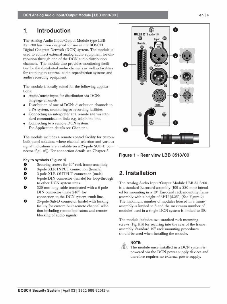
The module includes a remote control facility for custombuilt panel solutions where channel selection and varioussignal indications are available on a 25-pole SUB-D con-nector (fig.1 (6)). For connection details see Chapter 5.
Key to symbols (Figure 1)Securing screws for 19” rack frame assembly3-pole XLR INPUT connection (female) 3-pole XLR OUTPUT connection (male) 6-pole DIN connector (female) for loop-throughto other DCN system units.320 mm long cable terminated with a 6-pole DIN connector (male 240°) for connection to the DCN system trunk-line.25-pole Sub-D connector (male) with lockingfacility for custom built remote channel selec-tion including remote indicators and remoteblocking of audio signals.
en | 4
LBB 3513 audio 1/0Input
Output
Trunk
Remote
1
2
2
1
3
3
1
5
2
36
4
2
1
1
3
4
6
5
BOSCH
Push
Figure 1 - Rear view LBB 3513/00
2. InstallationThe Analog Audio Input/Output Module LBB 3513/00is a standard Eurocard assembly (100 x 220 mm) intend-ed for mounting in a 19” Eurocard rack mounting frameassembly with a height of 3HU (5.25”) (See Figure 2).The maximum number of modules housed in a frameassembly is limited to 8 and the maximum number ofmodules used in a single DCN system is limited to 30.
The module includes two standard rack mountingscrews (Fig.1(1)) for securing into the rear of the frameassembly. Standard 19” rack mounting proceduresshould be used when installing the module.
NOTE: The module once installed in a DCN system is powered via the DCN power supply devices andtherefore requires no external power supply.
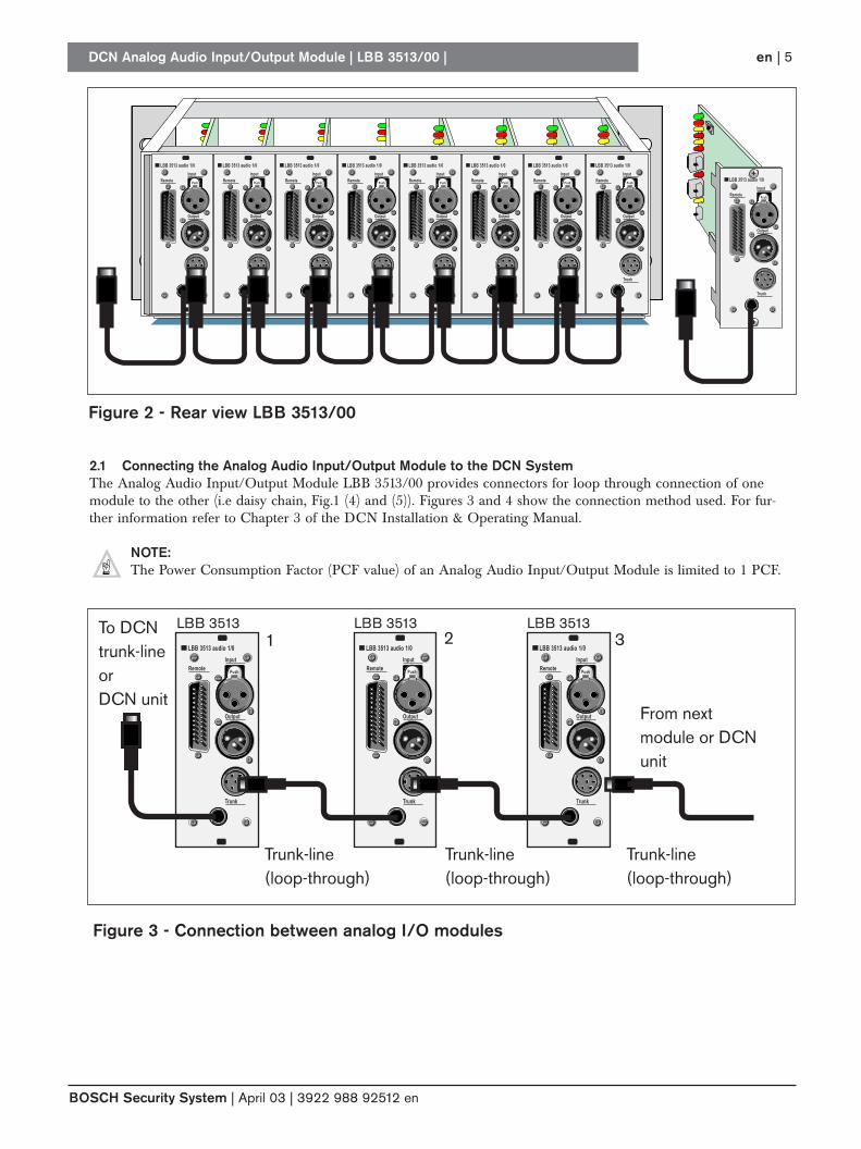
Figure 2 - Rear view LBB 3513/00
DCN Analog Audio Input/Output Module | LBB 3513/00 |
BOSCH Security System | April 03 | 3922 988 92512 en
en | 5
LBB 3513 audio 1/0
Input
Output
Trunk
Remote
LBB 3513 audio 1/0
Input
Output
Trunk
Remote
LBB 3513 audio 1/0
Input
Output
Trunk
Remote
LBB 3513 audio 1/0
Input
Output
Trunk
Remote
LBB 3513 audio 1/0
Input
Output
Trunk
Remote
LBB 3513 audio 1/0
Input
Output
Trunk
Remote
LBB 3513 audio 1/0
Input
Output
Trunk
Remote
LBB 3513 audio 1/0
Input
Output
Trunk
Remote LBB 3513 audio 1/0
Input
Output
Trunk
Remote
Push Push Push Push Push Push Push Push
Push
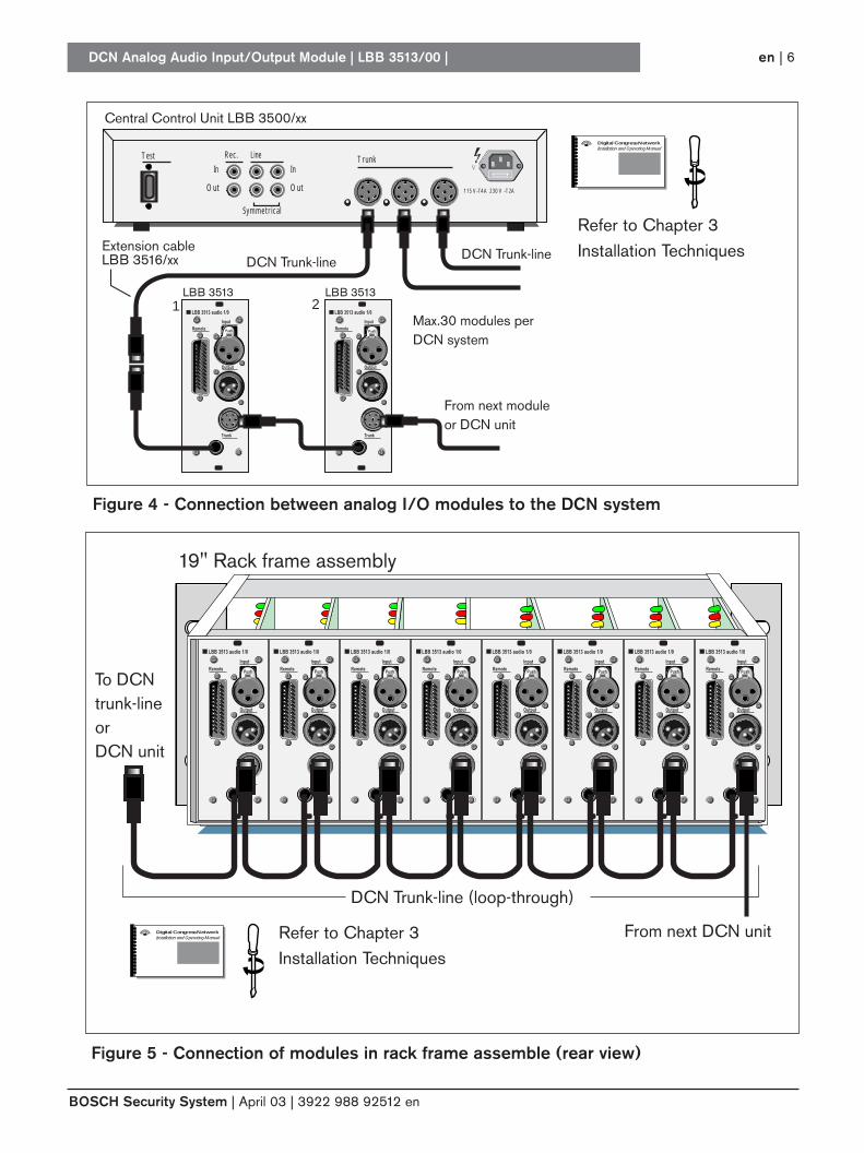
2.1 Connecting the Analog Audio Input/Output Module to the DCN SystemThe Analog Audio Input/Output Module LBB 3513/00 provides connectors for loop through connection of onemodule to the other (i.e daisy chain, Fig.1 (4) and (5)). Figures 3 and 4 show the connection method used. For fur-ther information refer to Chapter 3 of the DCN Installation & Operating Manual.
NOTE: The Power Consumption Factor (PCF value) of an Analog Audio Input/Output Module is limited to 1 PCF.
LBB 3513 audio 1/0
Input
Output
Trunk
Remote
LBB 3513 audio 1/0
Input
Output
Trunk
Remote
LBB 3513 audio 1/0
Input
Output
Trunk
Remote
From nextmodule or DCNunit
1 2LBB 3513LBB 3513 LBB 3513
3
Trunk-line(loop-through)
To DCNtrunk-lineor DCN unit
Trunk-line(loop-through)
Trunk-line(loop-through)
Push Push Push
Figure 3 - Connection between analog I/O modules
DCN Analog Audio Input/Output Module | LBB 3513/00 |
BOSCH Security System | April 03 | 3922 988 92512 en
en | 6
LBB 3500/10 /30Test Rec. Line
In
Out
In
Out
Symmetrical
Trunk
115 V-T4A 230 V -T2A
DCN Trunk-lineDCN Trunk-lineExtension cableLBB 3516/xx
Central Control Unit LBB 3500/xx
LBB 3513 audio 1/0
Input
Output
Trunk
Remote
LBB 3513 audio 1/0
Input
Output
Trunk
Remote
1 2LBB 3513LBB 3513
From next module or DCN unit
Max.30 modules perDCN system
PushPush
Figure 4 - Connection between analog I/O modules to the DCN system
From next DCN unit
To DCNtrunk-lineorDCN unit
19" Rack frame assembly
DCN Trunk-line (loop-through)
LBB 3513 audio 1/0
Input
Output
Trunk
Remote
LBB 3513 audio 1/0
Input
Output
Trunk
Remote
LBB 3513 audio 1/0
Input
Output
Trunk
Remote
LBB 3513 audio 1/0
Input
Output
Trunk
Remote
LBB 3513 audio 1/0
Input
Output
Trunk
Remote
LBB 3513 audio 1/0
Input
Output
Trunk
Remote
LBB 3513 audio 1/0
Input
Output
Trunk
Remote
LBB 3513 audio 1/0
Input
Output
Trunk
Remote Push Push Push Push Push Push Push Push
Figure 5 - Connection of modules in rack frame assemble (rear view)
Digital Congress NetworkInstallation and Operating Manual
Refer to Chapter 3Installation Techniques
Digital Congress NetworkInstallation and Operating Manual Refer to Chapter 3
Installation Techniques
2.2 Initializing the ModuleBefore the Analog Audio Input/Output Module can beused in a DCN system, the module must first be initial-ized for recognition by DCNs Central Control Unit(CCU). This is given in the form of an address allocatedto the module by the CCU. An ‘Init/de-Init’ push-but-ton switch (Fig. 7 (12)) with LED indication (red) ((Fig. 7(10)) located on the modules PCB is used for this proce-dure.
To initialize a module proceed as follows:
A module not initialized is identified when all its LEDsare ON. To initialize a unit proceed as follows:1. Press the units init/de-init switch (Fig.7(12)).2. All LEDs indicate their normal status, the ini
tialization LED (Fig.7(10) must be OFF.3. To de-initialize a unit momentarily press the init/de-
init switch again. All LEDs are ON.
2.3 Connecting Audio Inputs and Outputs
INPUTS (refer to Figure 6.)The Analog Audio Input/Output Module has a single 3-pole XLR connector (female) (Fig. 1(2)) for the connec-tion of a symmetrical analog audio line input with anoptional input transformer for galvanic separation (typeTR/BV3) (see Fig.7 for location details). An asymmetri-cal connection is also possible. Each module can handleone external audio input. This input is selected via a 16-channel select switch (0 - 15) located at the front of themodule (Fig.7 (5)). An audio limiter circuit withON/OFF switch (Fig.7(1)) and LED indication (Fig. 7(2)) is available to optimize the channel signal levelinput for the best result. The limiter circuit is only activewhen the LED is ON.
In applications for remote interpretation (see Chapter 4)several Analog Audio Input/Output Modules can be setto the same input channel. However, the audio signal tothe connected interpreter desks and language channelselectors depends on the selected interlock settings of theinterpreter desks and the level of each channel..
NOTES: 1. For each external audio signal a single Analog
Audio Input/Output Module is required.2. Use of the audio input muting facility is
required when more than one (max.6) ’Analog Audio Input/Output Module’ is usedfor input to the same language channel (seesection 5 about remote control). The micro-phone interlock settings for the interpreterdesks, determine which interpreter desk or‘Analog Audio Input/Output Module’ may beactive.
OUTPUTSRefer to Figure 6.
The Analog Audio Input/Output Module has a single 3-pole XLR connector (male) (Fig. 1(3)) for the connectionof external audio distribution systems -such as a P.A. sys-tem with recording and monitoring facilities. Each module can handle one external audio output. This output is selected via a 16-channel select switch (0 -15) located at the front of the module (Fig.7 (3)).
The output is a symmetrical analog audio line output(via the modules output transformer) of one of theselected DCN language distribution channels.Asymmetrical connection is also possible.
NOTE: The Analog Audio Input/Output Module has thesame functionality as one output of the DCNAudio Media Interface Unit type LBB 3508/00which offers 4 outputs each having 15 channelsselected via a 15-position rotary selector switch.Intercom channels CANNOT be used fordistribution.
GENERALFor symmetrical and asymmetrical input and output con-nections refer to Chapter 5.
DCN Analog Audio Input/Output Module | LBB 3513/00 |
BOSCH Security System | April 03 | 3922 988 92512 en
en | 7
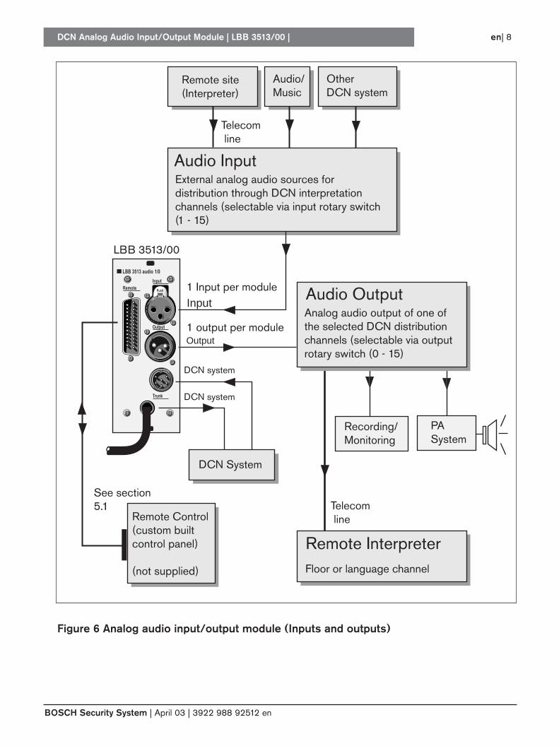
Figure 6 Analog audio input/output module (Inputs and outputs)
DCN Analog Audio Input/Output Module | LBB 3513/00 |
BOSCH Security System | April 03 | 3922 988 92512 en
en| 8
LBB 3513 audio 1/0
Input
Output
Trunk
Remote
Remote Control(custom built control panel)
(not supplied)
1 output per module
1 Input per module
LBB 3513/00
Floor or language channel
Input
Output
Remote Interpreter
DCN system
DCN system
Remote site(Interpreter)
Telecom line
Telecom line
External analog audio sources for distribution through DCN interpretation channels (selectable via input rotary switch(1 - 15)
Audio/Music
Other DCN system
DCN System
See section5.1
Audio Input
PA System
Recording/Monitoring
Push
Analog audio output of one of the selected DCN distribution channels (selectable via output rotary switch (0 - 15)
Audio Output
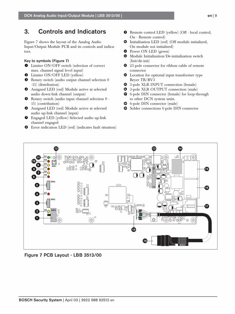
3. Controls and Indicators Figure 7 shows the layout of the Analog AudioInput/Output Module PCB and its controls and indica-tors.
Key to symbols (Figure 7)Limiter ON/OFF switch (selection of correct max. channel signal level input)Limiter ON/OFF LED (yellow) Rotary switch (audio output channel selection 0 -15) (distribution)Assigned LED (red) Module active at selected audio down-link channel (output)Rotary switch (audio input channel selection 0 -15) (contribution)Assigned LED (red) Module active at selected audio up-link channel (input) Engaged LED (yellow) Selected audio up-link channel engaged Error indication LED (red) (indicates fault situation)
Remote control LED (yellow) (Off - local control,On - Remote control)Initialisation LED (red) (Off module initialized, On module not initialized)Power ON LED (green) Module Initialization/De-initialization switch (Init/de-init)25-pole connector for ribbon cable of remoteconnectorLocation for optional input transformer type Beyer TR/BV3 3-pole XLR INPUT connection (female) 3-pole XLR OUTPUT connection (male) 6-pole DIN connector (female) for loop-through to other DCN system units.6-pole DIN connector (male)Solder connections 6-pole DIN connector
DCN Analog Audio Input/Output Module | LBB 3513/00 |
BOSCH Security System | April 03 | 3922 988 92512 en
en | 9
BOSCH
BCDEF
A
1
2
3
4
5
7
9
11
12
18
19
6
8
10
1413
15
16
17
D1
D2
D3
D4
D5
D6
D7
D8
SW3
SW2
SW1
SW4
Figure 7 PCB Layout - LBB 3513/00
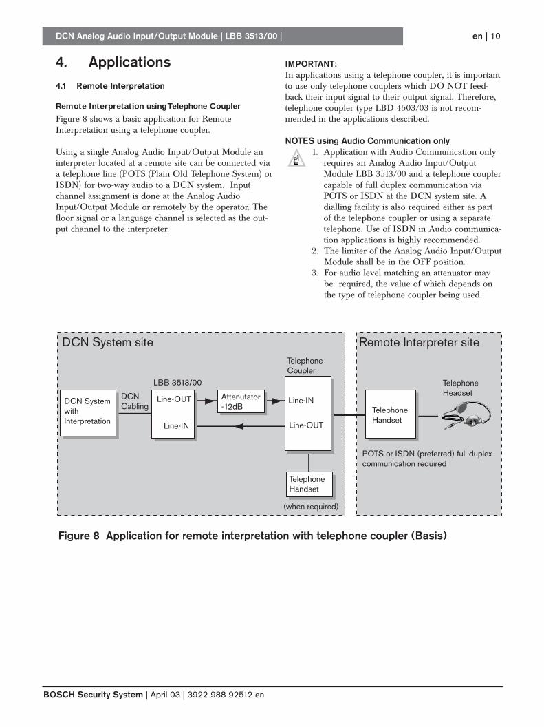
4. Applications4.1 Remote Interpretation
Remote Interpretation using Telephone Coupler
Figure 8 shows a basic application for RemoteInterpretation using a telephone coupler.
Using a single Analog Audio Input/Output Module aninterpreter located at a remote site can be connected viaa telephone line (POTS (Plain Old Telephone System) orISDN) for two-way audio to a DCN system. Inputchannel assignment is done at the Analog AudioInput/Output Module or remotely by the operator. Thefloor signal or a language channel is selected as the out-put channel to the interpreter.
IMPORTANT: In applications using a telephone coupler, it is importantto use only telephone couplers which DO NOT feed-back their input signal to their output signal. Therefore,telephone coupler type LBD 4503/03 is not recom-mended in the applications described.
NOTES using Audio Communication only1. Application with Audio Communication only
requires an Analog Audio Input/OutputModule LBB 3513/00 and a telephone couplercapable of full duplex communication viaPOTS or ISDN at the DCN system site. Adialling facility is also required either as partof the telephone coupler or using a separatetelephone. Use of ISDN in Audio communica-tion applications is highly recommended.
2. The limiter of the Analog Audio Input/OutputModule shall be in the OFF position.
3. For audio level matching an attenuator maybe required, the value of which depends onthe type of telephone coupler being used.
DCN Analog Audio Input/Output Module | LBB 3513/00 |
BOSCH Security System | April 03 | 3922 988 92512 en
en | 10
DCN System site Remote Interpreter site
DCN SystemwithInterpretation
Line-OUTDCNCabling
LBB 3513/00
TelephoneCoupler
Line-OUTLine-IN
TelephoneHandset
TelephoneHeadset
Line-INAttenutator-12dB
TelephoneHandset
POTS or ISDN (preferred) full duplexcommunication required
(when required)
Figure 8 Application for remote interpretation with telephone coupler (Basis)
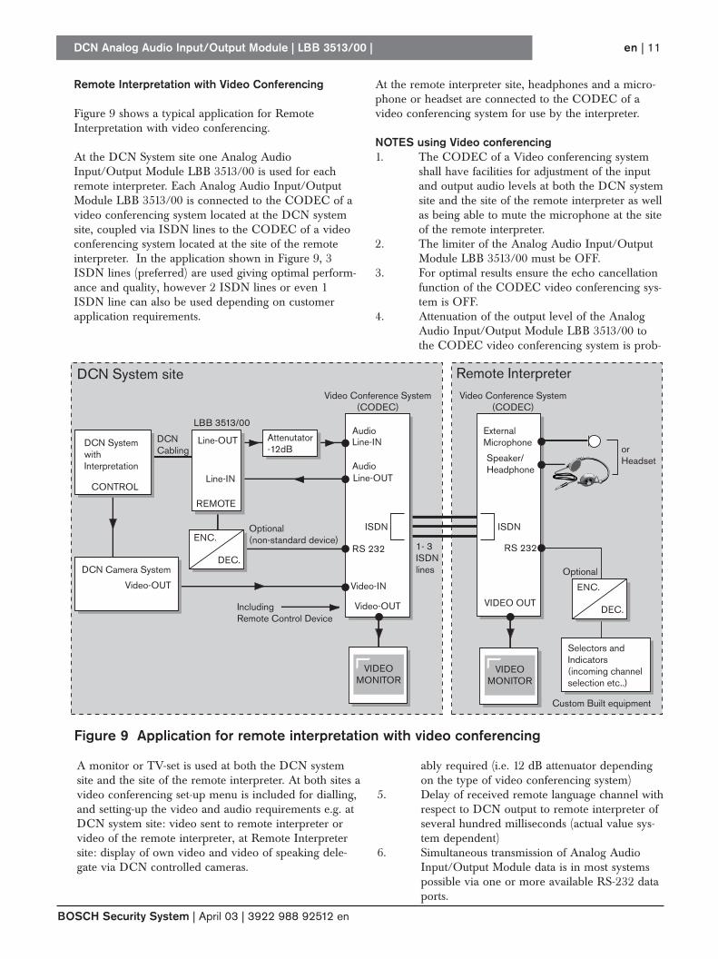
Remote Interpretation with Video Conferencing
Figure 9 shows a typical application for RemoteInterpretation with video conferencing.
At the DCN System site one Analog AudioInput/Output Module LBB 3513/00 is used for eachremote interpreter. Each Analog Audio Input/OutputModule LBB 3513/00 is connected to the CODEC of avideo conferencing system located at the DCN systemsite, coupled via ISDN lines to the CODEC of a videoconferencing system located at the site of the remoteinterpreter. In the application shown in Figure 9, 3ISDN lines (preferred) are used giving optimal perform-ance and quality, however 2 ISDN lines or even 1ISDN line can also be used depending on customerapplication requirements.
DCN Analog Audio Input/Output Module | LBB 3513/00 |
BOSCH Security System | April 03 | 3922 988 92512 en
en | 11
DCN SystemwithInterpretation
DCN Camera System
Line-OUT
REMOTE
DCNCabling
LBB 3513/00Audio
Audio
Video Conference System(CODEC)
Video Conference System(CODEC)
Video-OUT
Video-OUT Video-IN
ISDN
CONTROL
1- 3ISDN lines
DCN System site Remote Interpreter
Line-OUT
Optional(non-standard device)
Optional
IncludingRemote Control Device
Line-IN
Line-INExternalMicrophone
orHeadset
VIDEO OUT
Speaker/Headphone
Attenutator-12dB
ENC.
DEC.
ENC.
Custom Built equipment
Selectors andIndicators(incoming channelselection etc..)
DEC.
VIDEOMONITOR
VIDEOMONITOR
ISDN
RS 232RS 232
At the remote interpreter site, headphones and a micro-phone or headset are connected to the CODEC of avideo conferencing system for use by the interpreter.
NOTES using Video conferencing1. The CODEC of a Video conferencing system
shall have facilities for adjustment of the inputand output audio levels at both the DCN systemsite and the site of the remote interpreter as wellas being able to mute the microphone at the siteof the remote interpreter.
2. The limiter of the Analog Audio Input/Output Module LBB 3513/00 must be OFF.
3. For optimal results ensure the echo cancellationfunction of the CODEC video conferencing sys-tem is OFF.
4. Attenuation of the output level of the AnalogAudio Input/Output Module LBB 3513/00 tothe CODEC video conferencing system is prob-
Figure 9 Application for remote interpretation with video conferencing
A monitor or TV-set is used at both the DCN systemsite and the site of the remote interpreter. At both sites avideo conferencing set-up menu is included for dialling,and setting-up the video and audio requirements e.g. atDCN system site: video sent to remote interpreter orvideo of the remote interpreter, at Remote Interpretersite: display of own video and video of speaking dele-gate via DCN controlled cameras.
ably required (i.e. 12 dB attenuator dependingon the type of video conferencing system)
5. Delay of received remote language channel withrespect to DCN output to remote interpreter ofseveral hundred milliseconds (actual value sys-tem dependent)
6. Simultaneous transmission of Analog AudioInput/Output Module data is in most systemspossible via one or more available RS-232 dataports.
7. Functions for selection of incoming languagesvia a remote selector, remote status indicatorsfor channel assignment, error and engaged indi-cation, analog input/output audio muting etc.can be made available to the remote interpreterthrough project solutions. Project solutionsrequire dedicated hardware for control (selec-tors, LED indicators etc.) and coding/decodingat both sites into and from an RS-232 serial bitstream. At the DCN system site all connectionsare made to the Analog Audio Input/OutputModule LBB 3513/00. For functionality refer toSection 5.1.
NOTE: For more information and support the BOSCHSecurity Systems Customer Service and TechnicalSupport group can be contacted through yourlocal BOSCH sales organization.
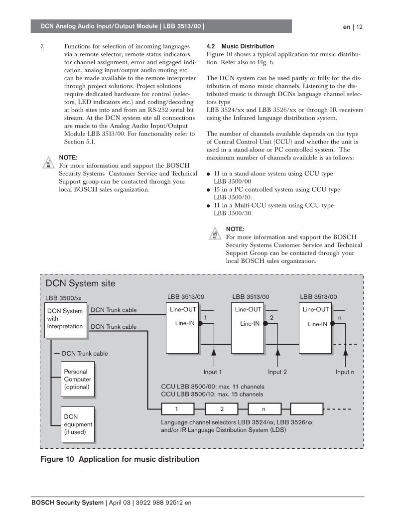
4.2 Music DistributionFigure 10 shows a typical application for music distribu-tion. Refer also to Fig. 6.
The DCN system can be used partly or fully for the dis-tribution of mono music channels. Listening to the dis-tributed music is through DCNs language channel selec-tors type LBB 3524/xx and LBB 3526/xx or through IR receiversusing the Infrared language distribution system.
The number of channels available depends on the typeof Central Control Unit (CCU) and whether the unit isused in a stand-alone or PC controlled system. Themaximum number of channels available is as follows:
● 11 in a stand-alone system using CCU typeLBB 3500/00
● 15 in a PC controlled system using CCU type LBB 3500/10.
● 11 in a Multi-CCU system using CCU typeLBB 3500/30.
NOTE: For more information and support the BOSCHSecurity Systems Customer Service and TechnicalSupport Group can be contacted through yourlocal BOSCH sales organization.
DCN Analog Audio Input/Output Module | LBB 3513/00 |
BOSCH Security System | April 03 | 3922 988 92512 en
DCN System site
Line-OUTDCN Trunk cable
DCN Trunk cable
DCN Trunk cable
Input 1
Language channel selectors LBB 3524/xx, LBB 3526/xxand/or IR Language Distribution System (LDS)
Input 2 Input n
LBB 3513/00
CCU LBB 3500/00: max. 11 channelsCCU LBB 3500/10: max. 15 channels
1 2 nLine-IN
Line-OUT
LBB 3513/00
Line-IN
Line-OUT
LBB 3513/00
Line-IN
DCNequipment(if used)
LBB 3500/xx
DCN SystemwithInterpretation
1 2 n
PersonalComputer(optional)
Figure 10 Application for music distribution
en | 12
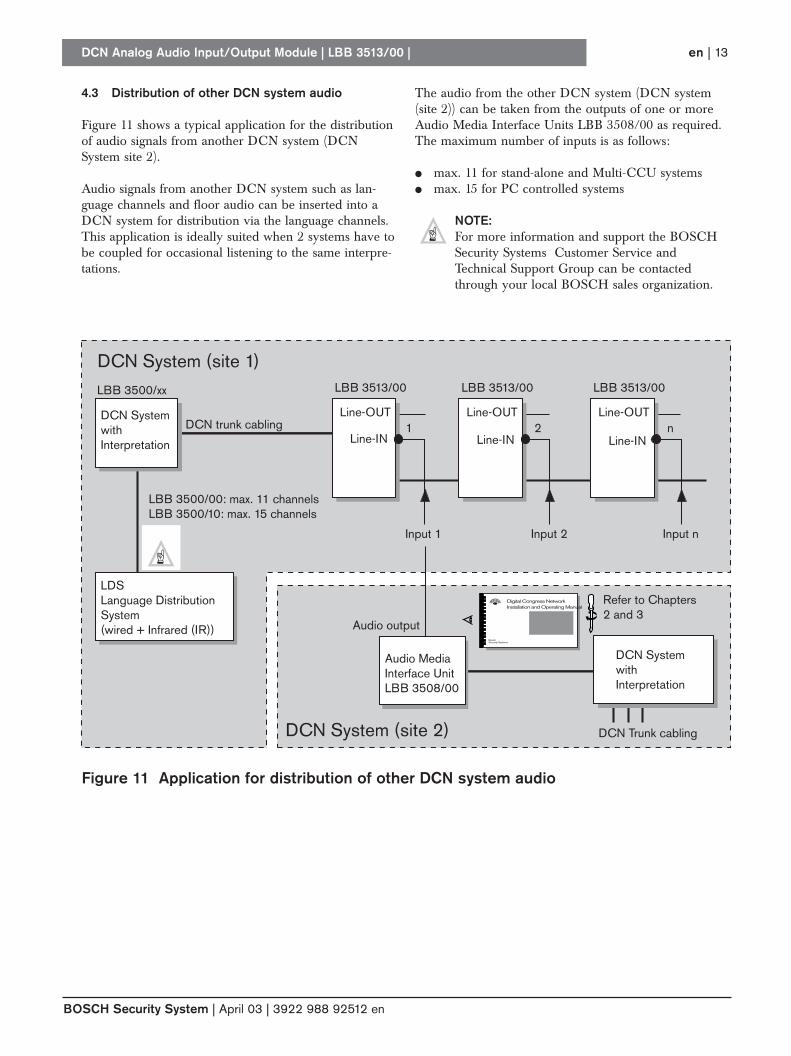
4.3 Distribution of other DCN system audio
Figure 11 shows a typical application for the distributionof audio signals from another DCN system (DCNSystem site 2).
Audio signals from another DCN system such as lan-guage channels and floor audio can be inserted into aDCN system for distribution via the language channels.This application is ideally suited when 2 systems have tobe coupled for occasional listening to the same interpre-tations.
The audio from the other DCN system (DCN system(site 2)) can be taken from the outputs of one or moreAudio Media Interface Units LBB 3508/00 as required. The maximum number of inputs is as follows:
● max. 11 for stand-alone and Multi-CCU systems● max. 15 for PC controlled systems
NOTE: For more information and support the BOSCHSecurity Systems Customer Service andTechnical Support Group can be contactedthrough your local BOSCH sales organization.
DCN Analog Audio Input/Output Module | LBB 3513/00 |
BOSCH Security System | April 03 | 3922 988 92512 en
en | 13
DCN System (site 1)
DCN System (site 2)
Line-OUTDCN trunk cabling
DCN Trunk cabling
Input 1
Audio output
Input 2 Input n
LBB 3513/00
LBB 3500/00: max. 11 channelsLBB 3500/10: max. 15 channels
1 2 nLine-IN
Line-OUT
LBB 3513/00
Line-IN
Line-OUT
LBB 3513/00
Line-IN
DCN SystemwithInterpretation
LDSLanguage DistributionSystem(wired + Infrared (IR))
LBB 3500/xx
Audio Media Interface UnitLBB 3508/00
Digital Congress NetworkInstallation and Operating Manual
BoschSecurity Systems
Refer to Chapters2 and 3
DCN SystemwithInterpretation
Figure 11 Application for distribution of other DCN system audio
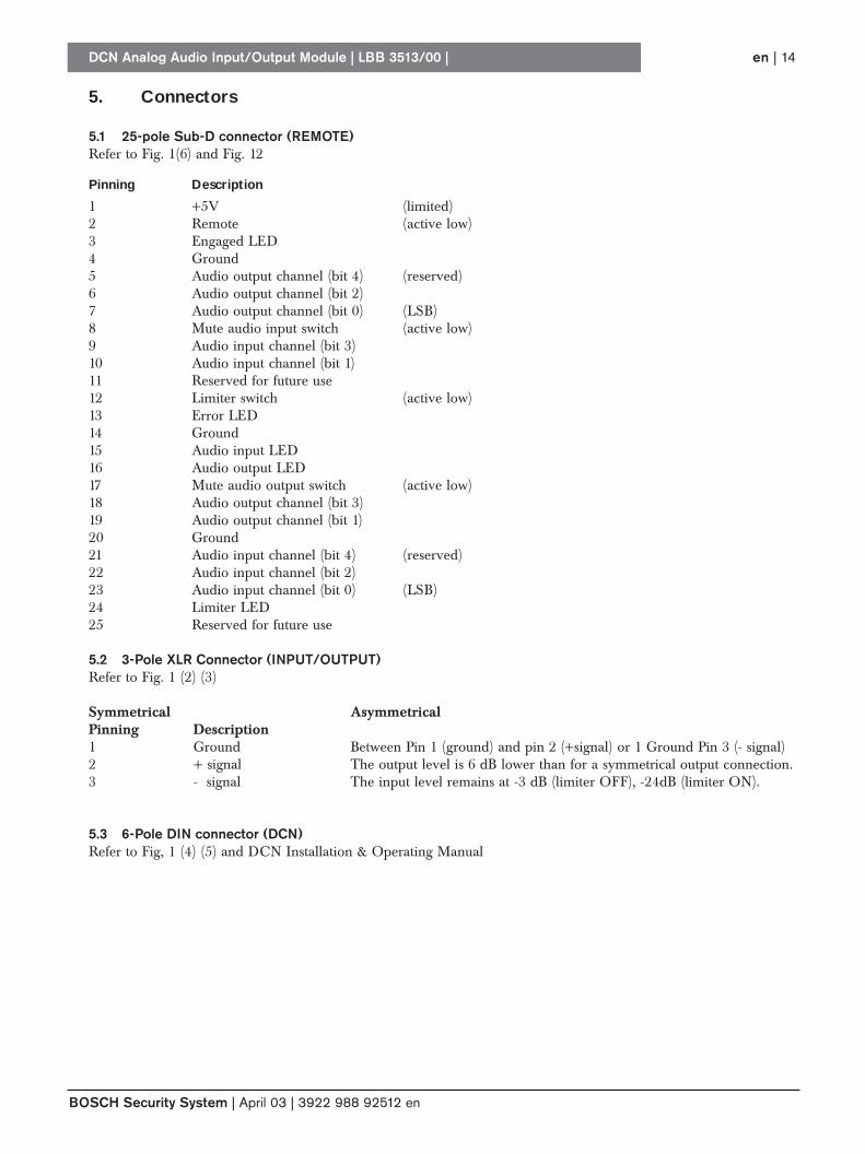
5. Connectors
5.1 25-pole Sub-D connector (REMOTE)Refer to Fig. 1(6) and Fig. 12
Pinning Description
1 +5V (limited)2 Remote (active low)3 Engaged LED4 Ground5 Audio output channel (bit 4) (reserved)6 Audio output channel (bit 2)7 Audio output channel (bit 0) (LSB)8 Mute audio input switch (active low)9 Audio input channel (bit 3)10 Audio input channel (bit 1)11 Reserved for future use12 Limiter switch (active low)13 Error LED14 Ground15 Audio input LED16 Audio output LED17 Mute audio output switch (active low)18 Audio output channel (bit 3)19 Audio output channel (bit 1)20 Ground21 Audio input channel (bit 4) (reserved)22 Audio input channel (bit 2)23 Audio input channel (bit 0) (LSB)24 Limiter LED25 Reserved for future use
5.2 3-Pole XLR Connector (INPUT/OUTPUT)Refer to Fig. 1 (2) (3)
Symmetrical AsymmetricalPinning Description1 Ground Between Pin 1 (ground) and pin 2 (+signal) or 1 Ground Pin 3 (- signal)2 + signal The output level is 6 dB lower than for a symmetrical output connection. 3 - signal The input level remains at -3 dB (limiter OFF), -24dB (limiter ON).
5.3 6-Pole DIN connector (DCN)Refer to Fig, 1 (4) (5) and DCN Installation & Operating Manual
DCN Analog Audio Input/Output Module | LBB 3513/00 |
BOSCH Security System | April 03 | 3922 988 92512 en
en | 14
DCN Analog Audio Input/Output Module | LBB 3513/00 |
BOSCH Security System | April 03 | 3922 988 92512 en
en | 15
5
1325122411
10
9
8
7
6
5
4
3
2
234
6 5 7
6 5 7
0 F
8421
8421
23456789
1
1
234
11
23
22
21
20
19
18
17
16
101112131415161718192021222324
15
14
X6SUBD25
+5V +5VMUTE INPUT SWITCH
OUTPUT CHANNELSELECTOR
INPUT CHANNELSELECTOR
MUTE OUTPUT SWITCH
AUD_IN_LEDENGAGAGED_LED
MUTE_OUTPUT -
MUTE_INPUT -IN4IN3IN2IN1IN0
LIMIT_LEDLIMIT_SWITCH-TESTERROR
OUT4OUT3OUT2
OUT0OUT1
AUD_OUT_LED
2526
LIMITER SWITCH
LIMITER ENGAGEDERROR AUDIO OUTPUT AUDIO INPUT
RED RED REDYELLOW YELLOW
1 2 3 4
0 F
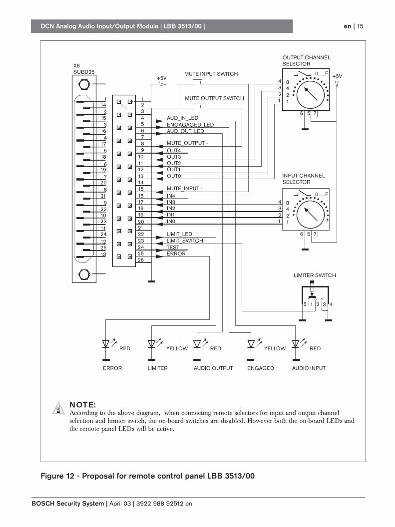
Figure 12 - Proposal for remote control panel LBB 3513/00
NOTE:According to the above diagram, when connecting remote selectors for input and output channelselection and limiter switch, the on-board switches are disabled. However both the on-board LEDs andthe remote panel LEDs will be active.
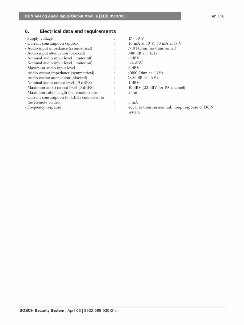
6. Electrical data and requirements- Supply voltage : 17 - 40 V- Current consumption (approx.) : 40 mA at 40 V, 50 mA at 17 V- Audio input impedance (symmetrical) : >10 kOhm (no transformer)- Audio input attenuation (blocked) : >80 dB at 1 kHz- Nominal audio input level (limiter off) : -3dBV- Nominal audio input level (limiter on) : -24 dBV- Maximum audio input level : 6 dBV- Audio output impedance (symmetrical) : <600 Ohm at 1 kHz- Audio output attenuation (blocked) : > 80 dB at 1 kHz- Nominal audio output level (-9 dBFS) : 1 dBV- Maximum audio output level (0 dBFS) : 10 dBV (22 dBV for PA-channel)- Maximum cable length for remote control : 25 m- Current consumption for LEDs connected to
the Remote control : 5 mA- Frequency response : equal to transmission link freq. response of DCN
system
DCN Analog Audio Input/Output Module | LBB 3513/00 |
BOSCH Security System | April 03 | 3922 988 92512 en
en | 16
DCN Analog Audio Input/Output Module | LBB 3513/00 |
BOSCH Security System | April 03 | 3922 988 92512 en
en | 17
© 2003 Bosch Security Systems B.V.Data subject to change without noticeApril 03 | 3922 988 92512 en
For more information please visit www.boschsecuritysystems.com


