128
Stock ID: DDC-IOM August, 1997 '1997 Environmental Technologies, Inc. Largo, FL DDC CONTROL SYSTEM INSTALLATION, OPERATION AND MAINTENANCE MANUAL

Stock ID: DDC-IOMAugust, 1997
©1997 Environmental Technologies, Inc.
Largo, FL
DDCCONTROL SYSTEM
INSTALLATION,OPERATION AND
MAINTENANCE MANUAL
2
DDC CONTROL SYSTEM � I.O.M.
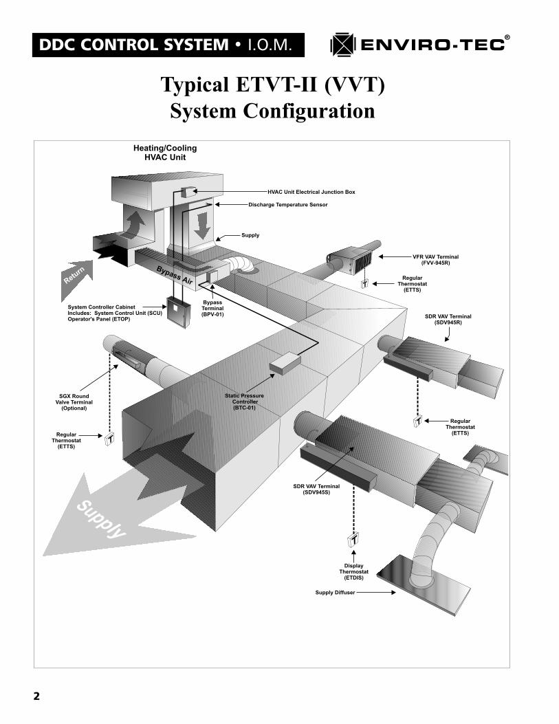
Typical ETVT-II (VVT)System Configuration
3
I.O.M. � DDC CONTROL SYSTEM
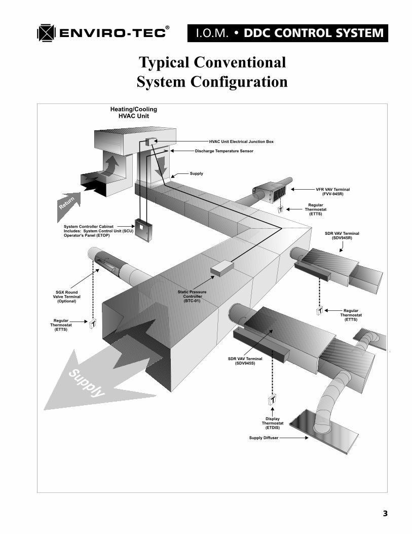
Typical ConventionalSystem Configuration
4
DDC CONTROL SYSTEM � I.O.M.
Table of Contents
Chapter 1 � General Component DescriptionSystem Control Unit - (SCU) .............................................................................................................................. 7Static Pressure Controller - (BTC) ..................................................................................................................... 8Bypass Terminal - (BPV) ..................................................................................................................................... 8Single Duct VAV Terminal - (SDV945) ............................................................................................................... 9Variable Volume Fan Powered VAV Terminal - (FVV945) ................................................................................. 9Constant Volume Fan Powered VAV Terminal - (FCV945) ................................................................................ 9Thermostats - ETTS or ETDIS .......................................................................................................................... 10Quick Wire Pre-Terminated Cables - (QW) ...................................................................................................... 10Communication Interface Converter - (ETINT1) ............................................................................................. 10Modem Interface Cable - (ETNUL) .................................................................................................................. 10Access Tool - (ETKEY) ....................................................................................................................................... 11Quick Wire Cable Coupler - (ETQWX) .............................................................................................................. 11Bus Communication Adapter - (ETRS) .............................................................................................................. 11Front End PC Communication Converter Card - (ETCOMV) .......................................................................... 11Duct Temperature Sensor - (ETDSD and ETDSDL) .......................................................................................... 11Remote Temperature Sensors - (ETDSDL25 and ETDSDL50) .......................................................................... 11
Chapter 2 � Component Installation GuidelinesInspection .......................................................................................................................................................... 12Coordination of Trades ..................................................................................................................................... 12Location of Component Installation ................................................................................................................. 12VAV Terminal Installation - SDV, FVV or FCV Control Sequences ................................................................. 12Bypass Terminal Installation - BPV Control Sequences ................................................................................... 12Static Pressure Controller - BTC Control Sequences ....................................................................................... 13Thermostats - ETTS and ETDIS ........................................................................................................................ 13Wall Board Mounting (Figure G.1) ................................................................................................................... 132" X 4" Single Gang Box Mounting (Figure G.2) ............................................................................................. 13System Control Unit - SCU ............................................................................................................................... 14Discharge Temperature Sensor - ETDSDL ....................................................................................................... 14
Chapter 3 � Component Wiring GuidelinesWARNING: ........................................................................................................................................................ 16General ............................................................................................................................................................. 16Communications Wiring .................................................................................................................................... 16Power Wiring .................................................................................................................................................... 19Control Wiring .................................................................................................................................................. 19External Device Wiring ..................................................................................................................................... 19
Chapter 4 � Control Sequence DrawingsControl Sequence Drawings ............................................................................................................................. 20

5
I.O.M. � DDC CONTROL SYSTEM
Chapter 5 � Software Configuration and OperationSoftware Component Identification .................................................................................................................. 37Determining a Unit Address ............................................................................................................................. 37Setting a Unit Address ....................................................................................................................................... 38Running the VTMON Setup and Monitor Program .......................................................................................... 40Using the VTMON Setup and Monitor Program .............................................................................................. 40Command Line Options .................................................................................................................................... 41
�ETI DDC NETWORK� Screen ....................................................................................................................... 44�System Control Unit - Monitor� Screen ......................................................................................................... 46�System Control Unit - Schedule� Screen ........................................................................................................ 48�System Control Unit - Auxiliary Schedule� Screen ........................................................................................ 50�System Control Unit - Configuration Settings� Screen .................................................................................. 52�System Control Unit - AHU Control Settings� Screen ................................................................................... 55�Pressure Sensor Monitor & Configuration Settings� Screen ......................................................................... 58�Zone (Address) - Monitor� Screen ................................................................................................................. 60�Zone (Address) - User Settings� Screen ......................................................................................................... 63�Zone (Address) - General Configuration Settings� Screen ............................................................................ 65�Zone (Address) - Low Level Configuration Settings� Screen ......................................................................... 68�Zone (Address) - Auxiliary Schedule� Screen ................................................................................................ 72Auxiliary Commands and �Help� Screens ....................................................................................................... 73Diagnostic Mode Test Variable Screens ............................................................................................................ 87
Chapter 6 � Component Start Up GuidelinesVAV Zone Terminals .......................................................................................................................................... 96Bypass Terminals and Static Pressure Controllers ........................................................................................... 96System Control Units ........................................................................................................................................ 97Software Configuration ..................................................................................................................................... 97
Chapter 7 � SCU Operators Panel and ETDIS OperationETOP Operators Panel Operation ................................................................................................................... 99ETDIS Display Thermostat Operation ............................................................................................. 106
Chapter 8 � Static Pressure, Airflow and Temperature Calibration ProceduresTemperature Readings ..................................................................................................................................... 110Airflow Readings .............................................................................................................................................. 110BTC Initial Setup.............................................................................................................................................. 111BTC Static Pressure Calibration ..................................................................................................................... 112
Chapter 9 � System Password OperationInstalling a Password Using the VTMON Program ........................................................................................ 114Accessing a Password Protected System Using the VTMON Program ........................................................... 116Password Operation Using the ETOP Operators Panel ................................................................................. 116

6
DDC CONTROL SYSTEM � I.O.M.
Chapter 10 � System Modem CapabilitiesTo Accomplish Modem Setup ........................................................................................................................... 117Establishing Modem Communication with the Enviro-Tec DDC System ........................................................ 118
Chapter 11 � System Component TroubleshootingSystem Component Troubleshooting ............................................................................................................... 121
Chapter 12 � System Communications TroubleshootingSystem Communications Troubleshooting ...................................................................................................... 128
7
I.O.M. � DDC CONTROL SYSTEM
Chapter 1
ENVIRO-TEC DDC CONTROL SYSTEMGENERAL COMPONENT DESCRIPTIONS
A. System Control Unit - (SCU)The System Control Unit or SCU supports many functions provided by the Enviro-Tec DDC control system.Among these functions are:
1. Internal Clock/Calendar function for mode and auxiliary contact scheduling.2. Modem communications support for the entire system.3. Package or Air Handling unit control when utilizing a VVT type configuration.4. Communication interface for the VAV zone terminal network.5. Communication interface for the inter-SCU network.6. Operator Interface Panel.
There are four different models of System Control Unit with two different output configurations to the packageunit or air handling unit. They are:
1. SCUA8This SCU control sequence provides 8, field definable, dry contact outputs with field adjustable anti-cycletimers. This controller is a microprocessor based, stand-alone device with nonvolatile memory. This controllermay be networked via an RS485 protocol, twisted, shielded pair cable with up to 64 VAV terminals and a BTCstatic pressure controller. It may also be linked to 99 other SCU�s and their VAV terminals via a separate RS485,twisted and shielded pair cable network. The SCUA8 controller consists of the ETOP (operators panel), theETDUA8 (system control board), the ETDUX8 (output board), a control voltage transformer, a primary linevoltage disconnect switch (for control voltage transformer only), the ETDSDL (discharge duct temperaturesensor) and a wall mounted control enclosure. The SCUA8 control sequence may be found on drawing number16564.
2. SCUA4A2This SCU control sequence provides 4, field definable, dry contact outputs with field adjustable anti-cycletimers. It also provides for two modulating outputs for the control of chilled and/or hot water valves at the airhandler with field adjustable throttling range voltages anywhere between 0 VDC to 10 VDC. This controller isa microprocessor based, stand-alone device with nonvolatile memory. This controller may be networked via anRS485 protocol, twisted, shielded pair cable with up to 64 VAV terminals and a BTC static pressure controller.It may also be linked to 99 other SCU�s and their VAV terminals via a separate RS485, twisted and shielded paircable network. The SCUA4A2 controller consists of the ETOP (operators panel), the ETDUA8 (system controlboard), the ETDUX4A2 (output board), a control voltage transformer, a primary line voltage disconnect switch(for control voltage transformer only), the ETDSDL (discharge duct temperature sensor) and a wall mountedcontrol enclosure. The SCUA4A2 control sequence may be found on drawing number 16874.
3. SCULT8This SCU control sequence provides the same functions as the SCUA8 with the addition of Logging andTrending capabilities. The Logging and Trending option will be explained in a separate manual. The SCULT8controller consists of the ETOP (operators panel), the ETDULT (system control board), the ETDUX8 (outputboard), a control voltage transformer, a primary line voltage disconnect switch (for control voltage transformeronly), the ETDSD (discharge duct temperature sensor) and a wall mounted control enclosure. The SCULT8control sequence may be found on drawing number 17290.
8
DDC CONTROL SYSTEM � I.O.M.
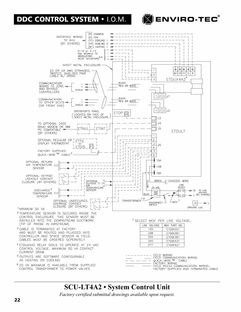
4. SCULT4A2This SCU control sequence provides the same functions as the SCUA4A2 with the addition of Logging andTrending capabilities. The Logging and Trending option will be explained in a separate manual. The SCULT4A2controller consists of the ETOP (operators panel), the ETDULT (system control board), the ETDUX4A2 (outputboard), a control voltage transformer, a primary line voltage disconnect switch (for control voltage transformeronly), the ETDSD (discharge duct temperature sensor) and a wall mounted control enclosure. The SCULT4A2control sequence may be found on drawing number 17289.
B. Static Pressure Controller - (BTC)The static pressure control sequence or BTC gives duct static pressure control capability to the Enviro-Tec DDCcontrol system. There are two different models of BTC for two different static pressure control applications.They are:
1. BTC01This BTC control sequence, powered by 24 VAC control voltage from the BPV01, gives stand-alone DDC staticpressure control by providing 24 VAC damper open and damper close signals to control in parallel 1, 2 or 3bypass terminals. The bypass control BTC01 is used in systems with a constant volume supply fan. Thiscontroller is a microprocessor based, stand-alone device with nonvolatile memory. This controller may benetworked via an RS485 protocol, twisted and shielded pair cable with VAV terminals and an SCU or operate ina stand-alone mode. The BTC01 controller consists of the ETDD6V (static pressure control board), the DwyerA-302 (static pressure sensing probe) and a duct mounted control enclosure. The BTC01 control sequence maybe found on drawing number 15459.
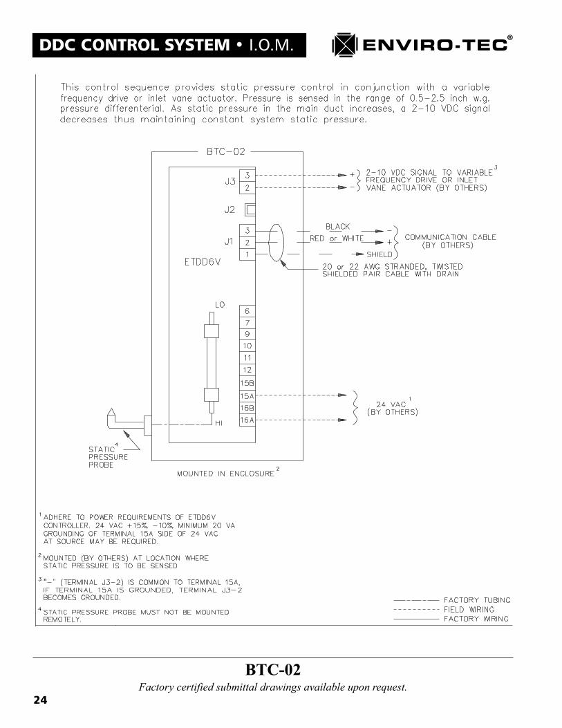
2. BTC02This BTC control sequence, requiring 24 VAC control voltage from an external power source, gives stand-aloneDDC static pressure control by providing a modulating 0 VDC to 10 VDC control signal which may be utilizedto control either a variable frequency fan motor drive, inlet vane type variable volume fan or discharge damperactuator. This controller is a microprocessor based, stand-alone device with nonvolatile memory. This control-ler may be networked via an RS485 protocol, twisted and shielded pair cable with VAV terminals and an SCU,or it can operate in a stand-alone mode. The BTC02 controller consists of the ETDD6V (static pressure controlboard), the Dwyer A-302 (static pressure sensing probe) and a duct mounted control enclosure. The BTC02control sequence may be found on drawing number 16777.
C. Bypass Terminal - (BPV)The Bypass Terminal or BPV is used in conjunction with the BTC01 static pressure controller on a constantvolume type package unit system. There is no inlet airflow measurement probe in this terminal as it is beingcontrolled by pressure as opposed to volume. There are two different models of the BPV bypass terminal. Theyare:
1. BPV01This BPV control sequence is the primary bypass terminal in either a single or multiple bypass terminal applica-tion. The BPV01 has an on board control voltage transformer that supplies power not only to itself, but to thesecondary bypass terminal or terminals (BPV02) and the BTC01 static pressure controller. The BPV01 does,however, rely on the BTC01 for damper actuator control voltage signals. The BPV01 consists of the SDR typebypass terminal itself, the ETACTRTAD (90 degree rotary damper actuator with AC to DC rectifier board), thecontrol voltage transformer and a primary line voltage disconnect switch (for control voltage transformer only).The BPV01 control sequence may be found on drawing number 15459.

9
I.O.M. � DDC CONTROL SYSTEM
2. BPV02This BPV bypass terminal is the second and, if required, third bypass terminal of a multiple bypass terminalapplication. The BPV02 has no on board control voltage transformer and relies on the BTC01 for damperactuator control voltage signals. The BPV02 consists of the SDR type bypass terminal itself and the ETACTRTAD(90 degree rotary damper actuator with rectifier board). The BPV02 control sequence may be found on drawingnumber 15459.
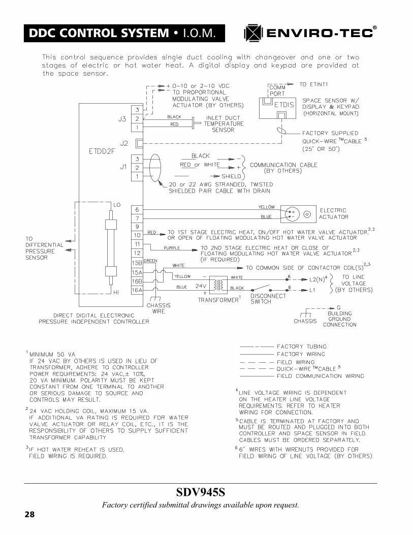
D. Single Duct VAV Terminal - (SDV945)The single duct VAV terminal control sequence or SDV945 provides stand-alone DDC, pressure independentcontrol capability to the single duct VAV terminal. This controller is a microprocessor based, stand-alone devicewith nonvolatile memory as well as three 24 VAC discrete outputs and a 0 VDC to 10 VDC modulating outputto support local heating devices. This controller is linked via a Quick Wire, pre-terminated cable to either theETTS (R) regular thermostat or the ETDIS (S) display thermostat. The �R� or �S� suffix on the SDV945 controlsequence designates which thermostat is used. This controller may be networked via an RS485 protocol, twisted,shielded pair cable with other VAV terminals, a BTC static pressure controller and an SCU, or it can operate ina stand-alone mode. The SDV945 consists of the SDR or SGX single duct type terminal (standard) with the�FlowStar� inlet probe, the ETDSD (inlet duct temperature sensor), the ETDD2F (zone control board), eitherthe ETTS or ETDIS thermostat, the ETACTRT (DC, 90 degree rotary damper actuator), a control voltage trans-former, a primary line voltage disconnect switch (for control voltage transformer only) and control enclosure.The SDV945R control sequence may be found on drawing number 15550. The SDV945S control sequence maybe found on drawing number 15551.
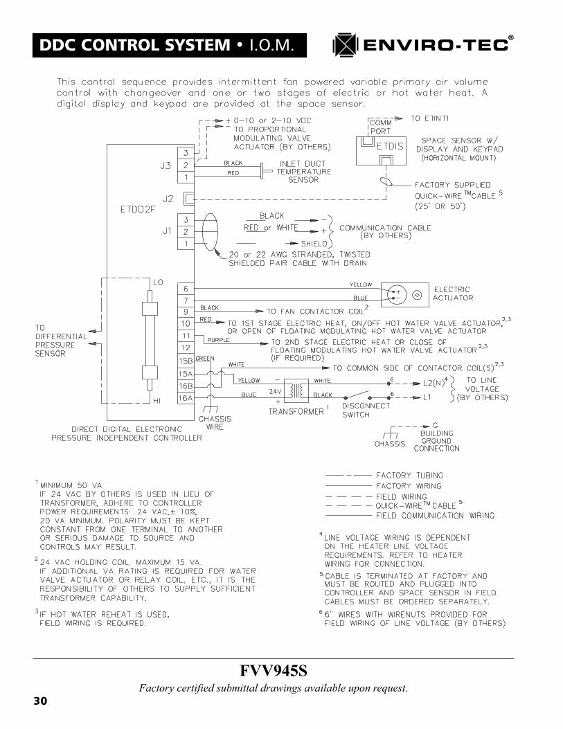
E. Variable Volume Fan Powered VAV Terminal - (FVV945)The variable volume parallel, fan powered VAV terminal control sequence or FVV945 provides stand-aloneDDC, pressure independent control capability to the parallel fan powered VAV terminal. This controller is amicroprocessor based, stand-alone device with nonvolatile memory as well as three 24 VAC discrete outputsand a 0 VDC to 10 VDC modulating output to support the fan motor and local heating devices. This controlleris linked via a Quick Wire, pre-terminated cable to either the ETTS (R) regular thermostat or the ETDIS (S)display thermostat. The �R� or �S� suffix on the FVV945 control sequence designates which thermostat is used.This controller may be networked via an RS485 protocol, twisted, shielded pair with other VAV terminals, aBTC static pressure controller and an SCU, or it can operate in a stand-alone mode. The FVV945 consists of theVFR parallel fan powered VAV terminal with the �FlowStar� inlet probe, the ETDSD (inlet duct temperaturesensor), the ETDD2F (zone control board), either the ETTS or ETDIS thermostat, the ETACTRT (DC, 90degree rotary damper actuator), a control voltage transformer, a primary line voltage disconnect switch (forcontrol voltage transformer only) and control enclosure. The FVV945R control sequence may be found ondrawing number 15458. The FVV945S control sequence may be found on drawing number 15547.
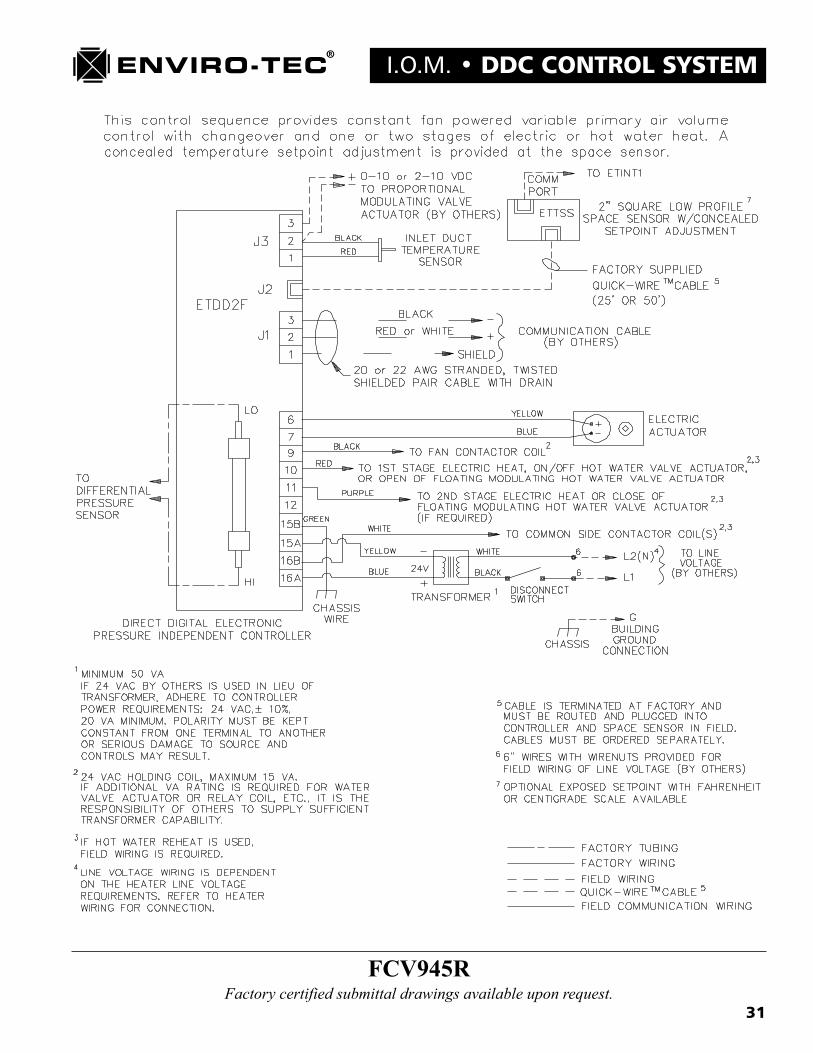
F. Constant Volume Fan Powered VAV Terminal - (FCV945)The constant volume series, fan powered VAV terminal control sequence or FCV945 provides stand-aloneDDC, pressure independent control capability to the series fan powered VAV terminal. This controller is amicroprocessor based, stand-alone device with nonvolatile memory as well as three 24 VAC discrete outputsand a 0 VDC to 10 VDC modulating output to support the fan motor and local heating devices. This controlleris linked via a Quick Wire, pre-terminated cable to either the ETTS (R) regular thermostat or the ETDIS (S)display thermostat. The �R� or �S� suffix on the FCV945 control sequence designates which thermostat is used.This controller may be networked via an RS485 protocol, twisted, shielded pair with other VAV terminals, aBTC static pressure controller and an SCU, or it can operate in a stand-alone mode. The FCV945 consists of theCFR series fan powered VAV terminal with the �FlowStar� inlet probe, the ETDSD (inlet duct temperature
10
DDC CONTROL SYSTEM � I.O.M.sensor), the ETDD2F (zone control board), either the ETTS or ETDIS thermostat, the ETACTRT (DC, 90degree rotary damper actuator), a control voltage transformer, a primary line voltage disconnect switch (forcontrol voltage transformer only) and control enclosure. The FCV945R control sequence may be found ondrawing number 15548. The FCV945S control sequence may be found on drawing number 15549.
G. Thermostats - ETTS or ETDIS
1. ETTS (Regular Thermostat)The ETTS thermostat is a wall mounted device which incorporates a space temperature sensor, a hidden tem-perature set point dial, an unoccupied mode override button and a network communications port. The thermo-stat body is a locking type utilizing set screws to attach the cover to the base. There are 3 different ETTSmodels. The standard ETTS is for use with one VAV terminal. The ETTS2 model may be used with 2 VAVterminals and the ETTS3 may be used with 3 VAV terminals. This thermostat is connected to the VAV terminalvia a Quick Wire, pre-terminated cable. The ETTS consists of the ETTS thermostat board, the thermostat coverand base as well as wall board and 2" X 4" single gang box attaching hardware. The ETTS is used when thereis a �R� suffix designated on the VAV terminal control sequence.
2. ETDIS (Display Thermostat)The ETDIS thermostat is a wall mounted device which incorporates a space temperature sensor, an unoccupiedmode override button and a network communications port as well as a 4 digit, LED display with 6 buttonkeypad. This LED display enables the Heating and Cooling temperature set points to be viewed continuously, orthe current terminal CFM, current space temperature, current inlet duct temperature and terminal controlleraddress may be viewed by pressing a series of buttons on the keypad. The ETDIS also enables completeterminal set point configuration via use of the ETKEY and a series of HEX codes representing those configura-tions. The thermostat body is a locking type utilizing set screws to attach the cover to the base. This thermostatis connected to the VAV terminal via a Quick Wire, pre-terminated cable. The ETDIS consists of the ETDISthermostat board, the thermostat cover and base as well as wall board and 2" X 4" single gang box attachinghardware. The ETDIS is used when there is a �S� suffix designated on the VAV terminal control sequence.
H. Quick Wire Pre-Terminated Cables - (QW)The Quick Wire thermostat cables are pre-terminated for accurate and rapid termination of the thermostat. Thecable is a six conductor device with a 1/4" by 1/4" square, female connector on each end. The cable itself isavailable with either a plenum or non-plenum rated jacket. This cable is also available in two standard lengths,either 25 or 50 feet. Longer, non-standard lengths are also available. The plenum rated 25 and 50 foot cables aredesignated as the QW25 and QW50 respectively. The non-plenum rated cables incorporate a �N� suffix with thecable designation.
I. Communication Interface Converter - (ETINT1)The ETINT1 is an RS485 to RS232 converter utilized when communicating with any system device or the entiresystem via a desktop or laptop computer. The ETINT1 connects to the serial RS232 port on the computer andlinks to any system device with a QW6N cable. The ETINT1 is equipped with 2 red LED�s. One LED indicatesactive communication transmission (TX) and one LED indicates active communication reception (RX).
J. Modem Interface Cable - (ETNUL)The ETNUL is a null modem cable required in the use of a modem connection with the SCU. This cable worksin conjunction with the ETINT1 converter and the QW6N cable to establish a modem communication link to thesystem.

11
I.O.M. � DDC CONTROL SYSTEMK. Access Tool - (ETKEY)
The ETKEY is an access tool used in conjunction with the ETDIS display thermostat to alter the configurationof a VAV terminal or BTC static pressure controller. The ETKEY may also be used to lock out the operatorspanel keypad on the SCU to prevent unauthorized access to system configuration set points. The ETKEY usesthe same female connector as the Quick Wire cables with a jumper wire added.
L. Quick Wire Cable Coupler - (ETQWX)The ETQWX allows for the coupling of two Quick Wire cables in the field should the situation arise that a singlecable is not of sufficient length.
M. Bus Communication Adapter - (ETRS)The ETRS cable allows for communication directly to the RS485 bus via a computer in conjunction with theETINT1 and two QW6N cables.
N. Front End PC Communication Converter Card - (ETCOMV)The ETCOMV is the permanent connection version of the ETINT1. The ETCOMV fits into an empty slot onthe front end computer mother board and permanently occupies one of the available RS232 serial ports via aconnection with the #85031 cable assembly. Either the SCU or a VAV terminal network may be routed to theETCOMV for permanent, on site communication capability.
O. Duct Temperature Sensor - (ETDSD and ETDSDL)The duct temperature sensors are utilized at the inlet of all VAV terminals and the discharge of the air handlingunit. They sense the duct temperature by altering their internal resistance as temperature changes. This resis-tance is sensed by the controller and translated into actual temperature. The short sensor or ETDSD is found inthe inlet of the VAV terminals. The long sensor or ETDSDL is supplied with the SCU and requires fieldmounting to sense the discharge temperature of the air handling unit.
P. Remote Temperature Sensors - (ETDSDL25 and ETDSDL50)The remote temperature sensor is used instead of the wall mounted thermostat in applications where a wallmounted device is not acceptable. This sensor is generally located in the return duct of the space and allows thecontroller to sense the return air temperature. The remote sensor is available in 25 and 50 foot lengths andutilizes a Quick Wire cable.
12
DDC CONTROL SYSTEM � I.O.M.
Chapter 2
ENVIRO-TEC DDC CONTROL SYSTEMCOMPONENT INSTALLATION GUIDELINES
A. InspectionUpon receipt of any and all equipment supplied by Environmental Technologies, check for any shippingdamage. Report any damage found immediately to the carrier. Also, inspect all equipment before and afterinstallation for damage caused by abuse or mishandling.
B. Coordination of TradesContractor must insure that all trades involved in the handling, installation, wiring and startup of any Enviro-TecDDC control system components be supplied with a copy of this Operations and Maintenance manual as well assubmitted control sequence data and/or drawings prior to installation. This is a critical step that must be takenin order to avoid damage that would void any warranties, written or implied, covering the system component inquestion.
C. Location of Component InstallationAccessibility must be considered when locating and installing the various Enviro-Tec DDC system components.Typically, these components will be wired after installation and access to some components may be necessaryduring start up or balancing of the system. Insure that the control enclosure covers on all system componentscan be removed without interference from walls, ductwork, conduit, hanger brackets, etc. Components may notbe mounted in locations where ambient temperatures will exceed 125 degrees F or fall below 35 degrees F.Components may not be installed in locations which are not protected from the weather as the control enclosuresare not weatherproof or weather resistant.
D. VAV Terminal Installation - SDV, FVV or FCV Control SequencesThe VAV terminals should be hung in the horizontal position with the terminal tag arrow pointing up. Sheetmetal hanger straps of sufficient gauge are required. If flexible ducting is used for inlet connections, make surethat a compression strap is utilized to insure an airtight joint. Discharge slip and drive joints should be sealed toinsure an airtight connection.
E. Bypass Terminal Installation - BPV Control SequencesThe BPV bypass terminals should be hung in the horizontal position with the terminal tag arrow pointing up.Sheet metal hanger straps of sufficient gauge are required. Bypass terminals may be installed in one of twoconfigurations. The first would be in a ducted return system. In this configuration, the bypass terminal wouldbe located between the supply and return ducts. The BPV inlet is ducted to the supply duct and the discharge isducted to the return duct. This is the configuration that is recommended for use with series or parallel fanpowered VAV terminals. The second configuration is an open plenum return system. In this configuration, theBPV inlet is ducted to the supply duct and the discharge is open to the plenum space. No branchtakeoffs may be located upstream of the bypass terminal inlet. If an economizer is used, be certain that the returnair damper does not close off or interfere with the bypass terminal and its associated ductwork.
13
I.O.M. � DDC CONTROL SYSTEMF. Static Pressure Controller - BTC Control Sequences
The BTC static pressure controller should be installed two thirds to three quarters of the way down the supplyduct. Installing the static pressure sensor too close to the central unit may cause erratic control. If multiplesupply duct trunks are used, install the BTC static pressure controller on the trunk with greatest potential airvolume usage. The BTC static pressure controller MUST be installed with the Dwyer A-302 pickup probepointing into the airflow. DO NOT remove the Dwyer A-302 static pressure probe from the BTC controlenclosure and mount remotely. The transducer on the BTC controller is calibrated for the specific amount oftubing used to connect it to the static pressure probe. A 3/8" to 1/2" hole must be drilled into to the duct. Theprobe is to be fitted into the hole and the control enclosure is to be attached to the duct using at least two sheetmetal screws. If insulated ducting is used, be certain that the probe has completely penetrated the insulation andis free in the air stream. Insure that there is no leakage around the pickup probe after installation. Use approvedduct sealant if required.
G. Thermostats - ETTS and ETDISThermostats are shipped separately from the VAV terminal units via parcel post ground shipment unless other-wise specified. Store these parts in a secure location until time for installation. Either the ETTS regular thermo-stat or the ETDIS display thermostat will function with any of the three types of VAV terminal control se-quences. If there are both types of thermostats on the job, be sure that the correct type of thermostat is installedin the specified location. Choose the location of the thermostat in the space carefully. Avoid locating thethermostat above any heat generating devices such as printers, refrigerators, space heaters, etc. These deviceswill cause the temperature sensor to register a false reading. These thermostats are designed for horizontalmounting and may be attached directly to wall board or a 2" X 4" single gang box. Mounting hardware for eitherinstallation method is supplied with each thermostat. It may also be necessary to seal the Quick Wire cableopening to eliminate the possibility of cooler or warmer air in the wall from influencing the space temperaturesensor. Use one of the following two methods for mounting the thermostat.
G.1 - Wall Board Mounting (Figure G.1)a. Drill holes in wall for Quick Wire cable and both wall anchors. Feed cable through wall and insert the
two wall anchors provided into the appropriate holes.
b. Run Quick Wire cable through L-shaped opening in the thermostat base and loosely fasten base to wallusing the two screws provided. Level base and tighten screws.
c. Mount thermostat PC board onto thermostat base so that the set point dial (ETTS) or LED display(ETDIS) is at the top. Use the small guide pins on the thermostat base to align the two components.Insert the two plastic retaining pins supplied into the opposite corners of the thermostat base from theguide pins.
d. Insert Quick Wire cable end into the bottom communication port on the thermostat PC board. Thecable end is keyed to go in one way only. DO NOT FORCE the cable end onto the bottomcommunications port. Be sure to tuck away any loose cable under the PC board so that it does notinterfere with the cover.
e. Snap the thermostat cover onto the base. Make sure that the vertical slots in the cover are on the leftside and the �Enviro-Tec� logo is on the right side. Align the cap screw cover locking holes on bothsides and install the two 4-40 painted cap screws provided. Tighten cover locking screws till snug.
G.2 - 2" X 4" Single Gang Box Mounting (Figure G.2)a. Install 2" X 4" single gang box into wall. Insure that box is recessed between 1/8" and 1/4" below wall
surface. Mounting bracket must have room to be recessed below flush level of wall in order forthermostat to flush mount to wall.

14
DDC CONTROL SYSTEM � I.O.M.
b. Install screw provided through right hand hole in mounting bracket into right hand threaded tab on 2"X 4" single gang box. Loosely tighten. Level mounting bracket and securely tighten screw.
c. Run Quick Wire cable through L-shaped opening in the thermostat base. Install screw providedthrough left hand holes of both thermostat base and mounting bracket and into the left hand threadedtab of 2" X 4" single gang box. Loosely tighten screw.
d. Install screw provided through center slot in thermostat base and into center hole of mountingbracket. Loosely tighten. Level thermostat base and securely tighten both left hand and center screws.
e. Mount thermostat PC board onto thermostat base so that the set point dial (ETTS) or LED display(ETDIS) is at the top. Use the small guide pins on the thermostat base to align the two components.Insert the two plastic retaining pins supplied into the opposite corners of the thermostat base from theguide pins.
f. Insert Quick Wire cable end into the bottom communication port on the thermostat PC board. Thecable end is keyed to go in one way only. DO NOT FORCE the cable end onto the bottomcommunications port. Be sure to tuck away any loose cable under the PC board so that it does notinterfere with the cover.
g. Snap the thermostat cover onto the base. Make sure that the vertical slots in the cover are on the leftside and the �Enviro-Tec� logo is on the right side. Align the cap screw cover locking holes on bothsides and install the two 4-40 painted cap screws provided. Tighten the locking screws till snug.
H. System Control Unit - SCUThe SCU should be mounted to the wall in a mechanical room or utility closet using the mounting flangesprovided. When choosing the location for the SCU, consideration must be given to the fact that this control unitmust be wired into the air handling and/or package unit, VAV terminal network, inter-SCU network, dischargetemperature sensor and line voltage. Also, the SCU should NOT be located where it would be subjected tohumidity or extremes in temperature. Do not exceed an ambient temperature range of 35 degrees F to 95 degreesF. Also, do not exceed a humidity range of 10% to 95% RH non-condensing.
I. Discharge Temperature Sensor - ETDSDLLocate the discharge temperature sensor in the supply duct downstream from the coils. This location mustrepresent the true air handler discharge temperature. Due to varying configurations, this location may differ bysystem. Trial and error positioning may be required. The discharge temperature sensor requires a 3/8" hole inthe duct for insertion and is secured using two self tapping sheet metal screws.

15
I.O.M. � DDC CONTROL SYSTEM
Wall AnchorsCable from Controller
Thermostat Face
Screws
Guide Pins PC Board
Retaining Pins ThermostatCover
Install Locking Set Screws
FIGURE G.1
FIGURE G.2
Junction Box
Thermostat Base Plate
Screws
Bracket
PC Board
ThermostatCover
Retaining Pins
16
DDC CONTROL SYSTEM � I.O.M.
Chapter 3
ENVIRO-TEC DDC CONTROL SYSTEMCOMPONENT WIRING GUIDELINES
A. WARNING:DO NOT APPLY POWER TO ANY ENVIRO-TEC SYSTEM COMPONENT BEFORE READING ANDCOMPLYING WITH ALL OF THE SECTIONS IN THIS CHAPTER AS WELL AS THE INDIVIDUALCONTROL SEQUENCE WIRING DRAWINGS AND THEIR NOTES. THESE DRAWINGS CAN BEFOUND IN CHAPTER 4 OF THIS MANUAL AS WELL AS ON THE INSIDE OF THE CONTROLENCLOSURE COVERS OF EACH SYSTEM COMPONENT. FAILURE TO COMPLY WITH THISINSTRUCTION MAY RESULT IN VOIDING OF THE PRODUCT WARRANTY.
B. General1. Local building codes should be checked to determine the necessity of using conduit or plenum rated
cable.
2. Communications, thermostat and DC voltage control wiring should not be routed close to any cable orconduit with cable carrying an AC voltage, electrically powered machinery or fluorescent lighting inorder to reduce the possibility of electrical noise interference.
3. Control sequence wiring diagrams for all Enviro-Tec DDC controls are found in Chapter 4 as well ason the inside of the control enclosure cover of each system component.
4. Duct temperature sensor, communication and optional contact closure wiring terminations are madevia screw terminals. To complete a proper connection, strip 1/4" of insulation from the wire. Turnscrew in terminal fully counterclockwise. Insert stripped portion of wire only into terminal and turnscrew fully clockwise till securely tight. Do not over tighten screws.
5. All 24 VAC power and output connections are made with 1/4" spade lug quick connecting typeterminals except for the ETDD6V control board used in the BTC01 and BTC02 control sequences.This alternative method is used so that there is a distinct difference between AC power connections andDC control and communication connections.
C. Communications WiringCommunications wiring is the most critical portion of the Enviro-Tec DDC control system installation. Themeans of routing the communications cable, and the connection method itself are critical in assuring a smoothand trouble free start up of the system. The type of cable which must be used to �Network� all of the systemcomponents together is called �twisted and shielded pair with drain�. This type of cable consists of two insu-lated conductors, one black and one either red or white, twisted around each other over the length of the cable.The two twisted conductors are wrapped in a foil shield and a third, non-insulated conductor or �drain�, runswith the foil over the length of the cable and allows for easy termination of the shield. Table C lists suitable�Alpha� and �Belden� cable cross reference part numbers. The following four guidelines MUST be adhered toin order to insure a successful and operational control system communication network.

17
I.O.M. � DDC CONTROL SYSTEM
Suggested Wire Types for Various Functions
Type
Communications
BTC-01, BPV-01,BPV-02
Alpha
58411
58114
Belden
87761
88444
Alpha
2211C
1174C
Belden
9462
8444
PLENUM RATED NON-PLENUM RATED
Table C
1. Cable RoutingAs shown in figure C.1.a, the communication network must be routed in a true, serial �Daisy Chain� type ofconfiguration. The network must begin at the SCU (if applicable) and be connected to the next communicatingdevice. From that device, the cable must continue to the next device only. With the exception of the first and lastdevice on each network which should have only one communication cable terminated at its� respective commu-nication port, each remaining device should have only two cables terminated at it�s communication port. Onecable in and one cable out. This method is to be used on both the SCU to VAV terminal network and the SCU toSCU network. The network shown in figure C.1.b is incorrect. �Sub-loops�, �T�s� and �Star� type networkrouting is unacceptable.
FIGURE C.1.A
Communication Cable is in "Daisy Chain" Series
ZONE1
SCU
A B C D E
F
GH
ZONE2
ZONE3
ZONE6
ZONE4
ZONE5
ZONE7
ZONE8
CORRECT
FIGURE C.1.B
ZONE1
ZONE6
ZONE4
SCU ZONE5
ZONE7
ZONE8
ZONE2
ZONE3
INCORRECT
Communication Cable is Randomly Routed

18
DDC CONTROL SYSTEM � I.O.M.2. Conduit UsageIf conduit is used at any point in the communications network, DO NOT run communications cable in the sameconduit with any AC voltage signal. The voltage level is immaterial. Any AC voltage signal in conduit withcommunications cable will induce noise and break up or possibly even eliminate the network communicationcapability. RS485 network communication cable, in or out of conduit, should be routed at least six inches awayfrom any conductors carrying an AC voltage signal, in or out of conduit.
3. Cable TerminationAs shown in figure C.3, only one inch of foil shielding should be removed from the communication cable whenpreparing to terminate the conductors. The foil shield is designed to reject RF interference from the conductorscarrying the RS485 signal. Removing more than one inch of foil will potentially turn the unshielded conductorinto an RF antenna which will induce noise onto the network and once again, break up or possibly eliminatecommunication capability.
4. Alternating Drain ConnectionsEach section of communication cable is terminated at each end to a communicating device. In order to eliminatethe possibility of a �Ground Loop�, or noise running back and forth over a conductor, the drain wire in thecommunication cable should be terminated at only one end. With the drain attached to ground at one end only,any induced noise on the conductors has to go to ground and stay there as the path back over the conductor to analternate ground has been eliminated. See figure C.4 for detail. When utilizing a SCU on a VAV terminal zonenetwork, make the first network drain connection at the SCU zone network communication port.
Communications Wiring Termination Illustration
FIGURE C.4
Zone 13-POSDeplugable
+-
From SCU
Drain Drain
Cut Drain
Zone 23-POSDeplugable
+--
Drain
Cut Drain
Zone 33-POSDeplugable
+--
FIGURE C.3
1/4"
1" Max

19
I.O.M. � DDC CONTROL SYSTEMD. Power Wiring
1. Standard Control TransformerThe Enviro-Tec DDC system components are equipped with standard control voltage transformers. Ensure thatthe primary voltage rating on the transformer matches the primary voltage to be used. When connecting build-ing power to a control voltage transformer, it is critical to also attach the building ground wire to the groundinglug or pigtail provided in the control enclosure. This grounding of the control enclosure is so important becausethe Enviro-Tec DDC controls reference all communication and analog signals to ground. Without this refer-ence, communication, air flow measurement and temperature measurement would not be possible.
2. Distributed 24 VACShould a distributed 24 VAC power source be utilized, there are several important points to observe. The first isto insure that the transformer chosen is of sufficient VA rating to supply 24 VAC to all VAV terminal controllersunder full load. The VA requirement for each control sequence is listed on the individual control sequencedrawing. The second is to insure that the wire used is of sufficient gauge to supply 24 VAC to all VAV terminalcontrollers under full load. The third, and most important, is to observe the polarity of the 24 VAC connectionson all of the controllers. Terminals 15 and 16 are the 24 VAC power connections on all controllers. For reasonsof safety and noise suppression, terminal 15 is the GROUNDED NEUTRAL leg of the 24 VAC input. Terminal16 is the PHASE leg of the 24 VAC input. Reversing the leads will damage the controller and void the warranty.It is the responsibility of the installing contractor to insure that the above steps are taken if a distributed 24 VACpower source is utilized in conjunction with the operation of an Enviro-Tec DDC control system.
E. Control WiringAny field control wiring which may be required is clearly indicated on the individual control sequence draw-ings. Examples would be the cable between the BTC01 static pressure controller and the BPV01 bypass termi-nal, the cable between the SCU and the packaged rooftop unit, the cable between the individual VAV terminalcontroller and a hot water valve, etc. Local building codes should be consulted for cable requirements. Load VAratings and distance of wire run are to be taken into consideration when determining required wire gauge. Sincethere is no way for the factory to know what the local codes or distance of wire runs will be on any giveninstallation where the Enviro-Tec DDC control system will be utilized, the responsibility of determining thecorrect wire gauge and type rests with the installing contractor.
F. External Device WiringModulating and floating point hot or chilled water valves, contactors, etc., are sometimes used in conjunctionwith and controlled by the Enviro-Tec DDC control system. When connecting an external device to an Enviro-Tec controller, first check the VA rating of the device. Then check the VA available from the control transformerafter it supplies power to the controller. The VA available is listed in the notes of the individual control se-quence. If the VA draw of the device exceeds the available VA of the control transformer, it is the responsibilityof the installing contractor to supply an additional transformer to power the external device. Also, some watervalves require an isolated control signal common. If this is so, a separate transformer will be required to powerthe valve as the signal common of the Enviro-Tec DDC controller is common to the grounded neutral leg of the24 VAC power input.
20
DDC CONTROL SYSTEM � I.O.M.
Chapter 4
ENVIRO-TEC® DDC CONTROL SYSTEMCONTROL SEQUENCE DRAWINGS
Page. Control Sequence Drawing Number
21 SCU-LT8 17290
22 SCU-LT4A2 17289
23 BTC-01, BPV-01, BPV-02 15459
24 BTC-02 16777
25 SDV942R 15545
26 SDV942S 15546
27 SDV945R 15550
28 SDV945S 15551
29 FVV945R 15458
30 FVV945S 15547
31 FCV945R 15548
32 FCV945S 15549
33 SDV945DL 17304
34 FVV945DL 17308
35 FCV945DL 17306
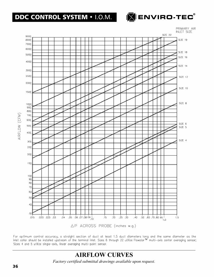
36 Air Flow Curves 15883

21
I.O.M. � DDC CONTROL SYSTEM
SCU-LT8 � System Control UnitFactory certified submittal drawings available upon request.
22
DDC CONTROL SYSTEM � I.O.M.
SCU-LT4A2 � System Control UnitFactory certified submittal drawings available upon request.

23
I.O.M. � DDC CONTROL SYSTEM
BTC-01, BPV-01, BPV-02Factory certified submittal drawings available upon request.
24
DDC CONTROL SYSTEM � I.O.M.
BTC-02Factory certified submittal drawings available upon request.

25
I.O.M. � DDC CONTROL SYSTEM
SDV942RFactory certified submittal drawings available upon request.

26
DDC CONTROL SYSTEM � I.O.M.
SDV942SFactory certified submittal drawings available upon request.

27
I.O.M. � DDC CONTROL SYSTEM
SDV945RFactory certified submittal drawings available upon request.
28
DDC CONTROL SYSTEM � I.O.M.
SDV945SFactory certified submittal drawings available upon request.

29
I.O.M. � DDC CONTROL SYSTEM
FVV945RFactory certified submittal drawings available upon request.
30
DDC CONTROL SYSTEM � I.O.M.
FVV945SFactory certified submittal drawings available upon request.
31
I.O.M. � DDC CONTROL SYSTEM
FCV945RFactory certified submittal drawings available upon request.

32
DDC CONTROL SYSTEM � I.O.M.
FCV945SFactory certified submittal drawings available upon request.

33
I.O.M. � DDC CONTROL SYSTEM
SDV945DLFactory certified submittal drawings available upon request.

34
DDC CONTROL SYSTEM � I.O.M.
FVV945DLFactory certified submittal drawings available upon request.

35
I.O.M. � DDC CONTROL SYSTEM
FCV945DLFactory certified submittal drawings available upon request.
36
DDC CONTROL SYSTEM � I.O.M.
AIRFLOW CURVESFactory certified submittal drawings available upon request.

37
I.O.M. � DDC CONTROL SYSTEM
Chapter 5
ENVIRO-TEC DDC CONTROL SYSTEMSOFTWARE CONFIGURATION AND OPERATION
A. Software Component IdentificationThere are several different software programs that are utilized by the Enviro-Tec DDC control system. Each ofthese different programs perform a specific series of functions and must work in conjunction with the otherprograms in the system. The SCU, BTC and VAV terminal controllers operate from a program that is stored inan IC chip called an EPROM (Erasable, Programmable, Read Only Memory). These EPROM�s are downloadedat the factory with a fixed set of operating instructions. Each EPROM also has a label on it that identifies thetype and revision of software which it contains. The following are some of the current revisions that can befound on the EPROM labels:
ENVIRO-TECETDU-A-008D-52A0
This is the current label found on the SCU controller board. �ETDU� designates the SCU program. The �A�designates the Intel N80C196KB microprocessor being used on board. (If the label does not contain the �A�, thecontroller is using the older Intel N80C198 microprocessor) The �008D� designates the software revision ofthe program. The �52A0� designates the program checksum.
ENVIRO-TECETDD-A-6V-004B-ECCC
This is the current label found on the BTC controller board. �ETDD� designates either a VAV terminal or BTCcontroller. The differentiation is made by the �6V� which designates the BTC program. The �A� designates theIntel N80C196KB microprocessor being used on board. (If the label does not contain the �A�, the controller isusing the older Intel N80C198 microprocessor) The �004B� designates the software revision of the program.The �ECCC� designates the program checksum.
ENVIRO-TECETDD-A-008G-1593
This is the current label found on the VAV terminal controller board. �ETDD� without being followed by �6V�designates a VAV terminal program. The �A� designates the Intel N80C196KB12 microprocessor being used onboard. (If the label does not contain the �A�, the controller is using the older Intel N80C198 microprocessor)The �008G� designates the software revision of the program. The �1593� designates the program checksum.
The remaining software programs utilized by the Enviro-Tec DDC control system are found on a system diskettesupplied with each job. Currently, there are 3 Enviro-Tec programs stored on diskette. These programs will beexplained in subsequent sections of this chapter. They are:
1. �VTMON� This is the system configuration and monitor program.2. �SETADDR� This is the unit set address program.3. �M1SETUP� This is the modem configuration program.
38
DDC CONTROL SYSTEM � I.O.M.Program revisions will be constantly upgraded as improvements and enhancements are made to the Enviro-TecDDC product line. The policy at Enviro-Tec is to upgrade these software programs so that they are backwardcompatible. This means that today�s program will work on the same network as a future upgraded programwithout any complications.
B. Determining a Unit AddressBecause all Enviro-Tec DDC control system components are connected on a communications network, theremust be some way to identify each separate controller from the others. This is accomplished by giving eachcontroller its own unique name or �address�. There is a specific structure to the scheme used to assign anaddress to each system component.
First, the SCU. Up to 100 SCU�s may be networked together on the inter-SCU network. The address of the SCUwill also designate its system number. An SCU can be addressed as 000, 100, 200, 300, 400 up to 9900.Respectively, SCU address 000 would be system 0, SCU address 100 would be system 1, SCU address 2100would be system 21, etc.
Second, the BTC. Each SCU can accommodate 1 BTC on its zone network. The BTC address will always endwith 65. The system number will precede the BTC address 65 on each system zone network. Respectively, thesystem 0 BTC would have an address of 65, the system 8 BTC would have an address of 865, the system 42 BTCwould have an address of 4265, etc.
Third, the VAV terminal controller. Each SCU can accommodate up to 64 VAV zone terminal controllers on itssystem zone network. As with the BTC�s, the VAV terminal controller�s address will be preceded with thesystem number. Respectively, system 0, VAV terminal 3 would have an address of 3; system 5, VAV terminal 16would have an address of 516; system 80, VAV terminal 63 would have an address of 8063, etc.
For convenience of addressing the different components on a zone network, the components do not have to bewired in any particular numerical address order. The SCU, however, must be wired at the physical beginning ofthe zone network. Also, you cannot install components belonging to different SCU systems on the same zonenetwork.
C. Setting a Unit AddressAfter determining the unit address for each system component, this information must then be downloaded to theindividual controller. There are several different methods by which this task may be accomplished. They are:
1. For the SCU, the SETADDR program or the SCU operators panel may be used.
2. For the BTC and the VAV terminal, the ETDIS display thermostat or the SETADDR program may be used.
a. To address the SCU with the SCU operators panel. After turning on the SCU power in accordance withthe instructions in chapter 6, �Current Mode" and "Standby� will be displayed. Press and release the Enterbutton 15 times and �SCU Identifier� will be displayed. Press and release the Next button 1 time. �UnitAddress� will be displayed. Enter the desired SCU address. Press and release the Mode button 1 time.Press and release the �0� button 1 time. Press and release the Enter button 1 time. �System Control Unit�will be displayed. The SCU address has been set.
b. To address any system component with the SETADDR program. This procedure requires an IBMcompatible computer, the system diskette supplied with the job, the ETINT1 and QW6N cables suppliedwith the job. Begin by inserting the system diskette into the computer�s floppy disk drive. Insert theETINT1 cable�s 9 pin female connector into the computer�s serial communication port. Note whichcommunications port is being used (1,2, etc.). Insert either end of the QW6N cable into the free end of the

39
I.O.M. � DDC CONTROL SYSTEMETINT1 cable. Turn the computer on and allow it to boot from the system diskette. Plug the free end of theQW6N cable into any 6 pin communication port on the device to be addressed. On the SCU, there are portson the ETDUA8 mother board as well as a port on the front of the operators panel. On the VAV terminal,the port on the top of the thermostat would be the most convenient. On the BTC, the port is on the controlleritself. At the DOS prompt �A:�, type �SETADDR� if port 1 is being used. If port 2,3 or 4 is being used,type �SETADDR 2� for port 2, etc. The computer will read the file from disk and display the following:
Set Address - 002 Copyright (c) 1993 Environmental Technologies, Inc.Current Address: 101Type in new address or Press <ESC> key to exit...Enter new address:
The standard address default is either 001 or 101. Simply enter the address number required, press the<ENTER> key and the new unit address is now set. Remove the QW6N cable end from the systemcomponent that has just been addressed, move to the next component and repeat only the addressingprocedure. There is no need to turn the computer off after each component is addressed.
c. To address the BTC or the VAV terminal with the ETDIS display thermostat. The ETDIS displaythermostat may be used alone or in conjunction with an ETTS regular thermostat to set the unitaddress on a VAV terminal controller.
If the VAV terminal controller uses an ETDIS display thermostat, insert the ETKEY (shipped with theETCOMPAC communication package) into the communication port at the top of the ETDIS displaythermostat.
If the VAV terminal controller uses an ETTS regular thermostat, insert one end of the QW6N cable into thecommunication port at the top of the ETTS regular thermostat and the other end into the bottom port of theETDIS display thermostat. Insert the ETKEY (shipped with the ETCOMPAC communications package)into the communication port at the top of the ETDIS display thermostat.
In either case, the following will be displayed on the ETDIS display:00 UA
Press the MODE button on the ETDIS. The current unit address will be displayed, example: 1 01
Using the COOLING adjust buttons, set the desired unit address. The right arrow button will increase theaddress number and the left arrow button will decrease the address number. Use the HEATING adjustbuttons to set the desired system number. Again, the right arrow button will increase the system numberand the left arrow button will decrease the system number.
Once the unit address is set, remove the ETKEY from the ETDIS display thermostat. The Heating andCooling setpoints will be displayed again. The address is now set in the EEPROM memory chip. If anETDIS has been used in conjunction with an ETTS, remove the QW6N cable and the ETDIS at thistime. Move on to the next unit.To set the unit address in the BTC, the ETDIS and QW6N cable combination must be inserted directlyinto the communication port on the ETDD6V static pressure control board. The above steps may thenbe utilized.
40
DDC CONTROL SYSTEM � I.O.M.D. Running the VTMON setup and monitor program
To communicate with an Enviro-Tec DDC control system via the VTMON software, the following will berequired:
1. An IBM compatible, DOS based computer, laptop or desktop.
2. The VTMON system disk found in the ETCOMPAC communication package.
3. The ETINT1 interface cable found with the ETCOMPAC communication package.
4. The QW6N 6 foot communication cable, also found with the ETCOMPAC.
Insert the ETINT1 cable�s 9 pin female connector into the computer�s serial communication port. Note whichcommunications port is being used (1,2, etc.). Insert either end of the QW6N cable into the free end of theETINT1 cable. Turn the computer on and allow it to boot from the system diskette or on-board fixed disk drive.If booting the computer from a fixed disk drive, do not attempt to run the VTMON program out of �Windows�.The VTMON program is strictly a �DOS� based operation and attempting to operate out of �Windows� maycause the computer to �lock-up�.
Plug the free end of the QW6N cable into the 6 pin communication port on any system device. At the DOSprompt (A: or C:), type VTMON and press the enter key. The drive will access the disk, read the program anddisplay the following on the screen:
VTMON 2.08a - Copyright (c) 1993 Environmental Technologies, Inc.( Press any key to continue. )
The 2.08a shown above is a program revision level and may change as program enhancements are made andupgrades are written. By pressing any key, the �ETI DDC NETWORK� screen will be displayed, the programwill attempt communication with all system components on the network and initialize the communication rou-tine of the SCU on the network if one is found. Note that the operator�s panel on the SCU will display �InterSCUPC Com in Progress� and the keypad on the operator�s panel will be disabled during VTMON operation.
E. Using the VTMON setup and monitor programOnce the VTMON program has accessed the Enviro-Tec DDC control system, it will be necessary to �maneu-ver� through the program to setup and monitor the various system components. The following keys will allowfor the manipulation of the VTMON program.
1. Cursor navigation keys. The up, down, left and right arrow keys will move the cursor to thedesired data location to access an address or alter setup data.
2. Screen change keys. The page up and page down keys allow the screens to be scrolled through.Once a system component has been accessed, the page up and page down keys allow the operatorto view the different screens related to that unit.
3. Data alteration. Once data is altered, the enter key will insure that the information is stored in theEEPROM chip and also automatically advances the cursor to the next data location.
4. Data Entry keys. The numeric, alphabetic, space bar and minus keys are used to change the variousconfiguration settings. Note that some configurations utilize a decimal point. In most cases, thisdecimal point is fixed. For example, to enter a temperature of 74.5 degrees, simply type in 745 andthe decimal point will automatically be inserted. To enter a negative value in a configuration, type inthe minus after entering a numerical value.

41
I.O.M. � DDC CONTROL SYSTEM5. Data Erase. The backspace key will erase or delete entered data one character at a time.
6. Optional Data configuration settings. Some configurations have a fixed set of options to choose from.The space bar will toggle through those options.
7. Returning to the Network Monitor screen. The Esc key will return the program to the NetworkMonitor screen from any other screen.
8. Exit the program. Pressing the Alt and X keys simultaneously will exit the VTMON program andreturn to DOS from the Network Monitor screen.
F. Command Line OptionsWhen calling up the VTMON program, several options are available to �customize� the program for specificneeds. These options are entered after the VTMON program name at the DOS prompt. The options are identi-fied as either a number or letter, depending on the individual option. A space must separate the program name(VTMON) and the option designation. Multiple options may be used at the same time. These options are:
1. Serial communication port. The VTMON program automatically defaults to the number 1 serial communications port on the PC. If, however, a different communication port is used such as 2, 3 or 4, this must bedesignated on the command line so that the program will know which port to communicate from. Forinstance, if serial port number 2 is used, type: VTMON 2 This will cause the program to communicatethrough serial communication port number 2.
2. Black and White screen display. When using a non-color, monochrome computer display, the command lineoption �b� should be used. This will produce a higher resolution display with sharper features on the blackand white or monochrome monitor. Type: VTMON b
3. Modem communication. When calling into an Enviro-Tec DDC system from a remote location, thecommand line option �m� should be used. This option will prompt the operator to enter the propermodem number to establish a communication link. Type: VTMON m
4. Non-SCU system. When initiating communication with the VTMON program to a system with no SCU, thecommand line option �n� should be used. This will format the program to eliminate the SCU search whennetwork communication is established. Type: VTMON n
5. Maintenance and Override. When a diagnostic, maintenance or balancing need occurs, the command lineoption �d� should be used. The diagnostic mode of operation allows for the manual override of outpts,an additional screen at the end of each individual component screen set to display low level controllerinformation and communication error status at the bottom of any screen. Type: VTMON d.
6. 9600 Baud Communication. When an internal ETCOMV card is used in a PC to communicate directlyto the Enviro-Tec DDC zone bus, the command line option �f� should be used. This will tell the PC toboost the communications baud rate from 2400 to 9600 for a direct, on the bus communication link.This option will not function when using the ETINT1 communication interface cable. Type:VTMON f.

42
DDC CONTROL SYSTEM � I.O.M.In
terS
CU
Com 14
Onl
ine
ET
I DD
C N
ET
WO
RK
Sys
tem
:1
SC
U
RT
U -
3B
TC
S
.P. C
ON
TR
OL
- 3
Pre
ss <
F1>
for
Hel
pS
pace
H
tng
Cln
g
Te
mp
Airf
low
Duc
tTe
mp
Set
ptS
etpt
Offs
et
Act
ual
Set
pt
Tem
p
Dis
char
ge T
emp.
:57
.3S
tatic
Pre
ssur
e:1.
25O
ccup
ied
Coo
ling
76.8
76.0
77.6
76.6
75.5
71.8
73.0
74.0
73.0
74.0
72.0
68.0
77.0
78.0
77.0
78.0
76.0
72.0
75 94 261
65 61 388
0.0
0.0
0.0
0.0
0.0
0.0
62 100
280
50 50 373
57.7
57.4
57.8
58.0
58.0
58.0
Ken
's O
ffice
Hal
lway
Bre
ak R
oom
Bill
's R
oom
Con
fere
nce
Rm
Jerr
y's
Roo
m
14:0
003
/07/
95
1 2 3 4 5 6 7 8 9 10 11 12 13 14
43
I.O.M. � DDC CONTROL SYSTEMIn
terS
CU
Com 14
On l
ine
Sys
t em
:1
SC
U R
TU
- 3
BT
C S
.P. C
ON
TR
OL
- 3
Pre
ss <
F1>
for
He l
pS
p ace
H
tng
Cln
g
Tem
pA
ir flo
w
Du c
tTe
mp
Se t
p tS
e tp t
Offs
e t
Act
u al
Se t
p t
Tem
p
Dis
cha r
g e T
emp.
:5 7
.3S
tatic
Pre
ssu r
e :1 .
2 5O
ccu p
ied
Coo
ling
7 6.8
7 6.0
7 7.6
7 6.6
7 5.5
7 1.8
7 3.0
7 4.0
7 3.0
7 4.0
7 2.0
6 8.0
7 7.0
7 8.0
7 7.0
7 8.0
7 6.0
7 2.0
7 5 9 4 2 61
6 5 6 1 3 88
0 .0
0 .0
0 .0
0 .0
0 .0
0 .0
6 2 1 00
2 80
5 0 5 0 3 73
5 7.7
5 7.4
5 7.8
5 8.0
5 8.0
5 8.0
Ke n
's O
ffice
Ha l
lway
Bre
a k R
o om
Bill
's R
o om
Con
fere
n ce
Rm
Jerr
y's
Ro o
m
14:0
00 3
/07 /
9 5
1 2 3 4 5 6 7 8 9 1 0 1 1 1 2 1 3 1 4
Rea
din
gC
on
fig
ura
tio
n
65%
ET
I DD
C N
ET
WO
RK

44
DDC CONTROL SYSTEM � I.O.M.
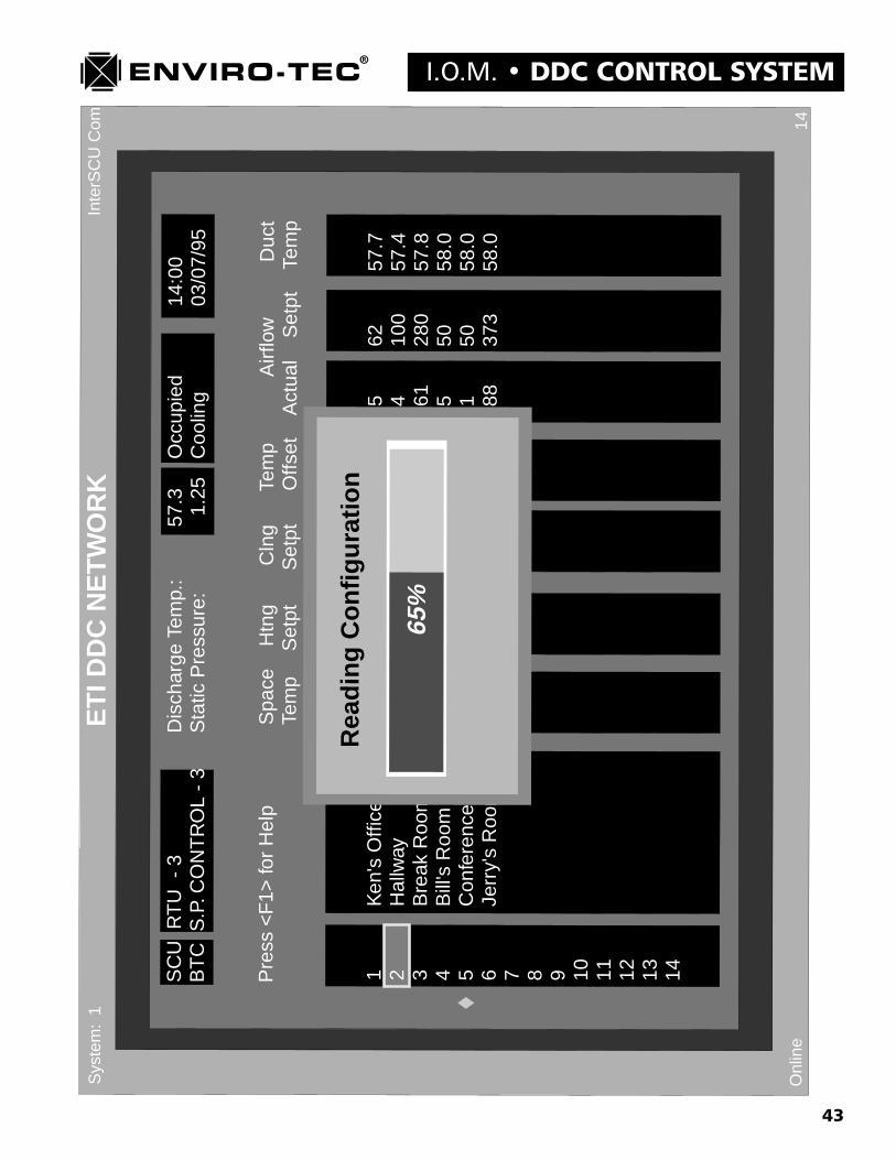
�ETI DDC NETWORK� Screen(see previous page for screen example)
This is the network monitor screen. It lists all of the responding controllers on the network and includes the criticaloperating parameters of each. There is a �Diamond� that scrolls down the left side of this screen. As the diamond pausesnext to each controller address, it updates all of the information displayed from that controller. Since the first ETI DDCNETWORK screen displays only up to address 14, the �Page Down� and �Page Up� keys will scroll to additionalscreens up to address 64 and back.
The following system information is displayed and updated on this screen continuously:1. Discharge Temp: Air handling unit discharge temperature.2. System Mode: Occupied or Unoccupied Mode.3. Time of day and date.4. System Operating Status: Cooling, Heating, Ventilation or Standby.5. Static Pressure: Pressure in inches of water column.
The following VAV terminal information is displayed and updated on this screen continuously:1. VAV terminal address and user established identifier.2. Space Temp: VAV control zone temperature in degrees F.3. Htng Setpt: Heating temperature setpoint.4. Clng Setpt: Cooling temperature setpoint.5. Temp Offset: Degrees space temp is above cooling or below heating setpoint.6. Airflow Actual: Current actual primary airflow through VAV terminal in CFM.7. Airflow Setpt: Current setpoint for primary airflow through VAV terminal in CFM.8. Duct Temp: VAV terminal inlet duct temperature in degrees F.9. System: System number (0-99) currently being communicated with. (Upper left corner)10. Polling time: Time in seconds till next system polling. (Lower right corner)11. Online/Offline: Indicates whether VTMON program is communicating. (Lower left corner)
On the sample screen, pictured on the previous page, notice the reverse video block highlighting address number 2. Thisblock will allow access to whichever unit name (SCU or BTC) or address (VAV terminal) it highlights. The up arrowand down arrow keys will move this block up and down the address column so that the desired address may be accessed.To access a specific unit, move the reverse video block to the unit address or name desired and press the Enter key. A�Reading Configuration� block will appear in the center of the screen. The sample screen displayed on the next pageshows that the enter key was pressed while the reverse video block was located on address number 2. The �ReadingConfiguration� block shows that the computer running the VTMON program has read 65% of the VAV terminal unit 2configuration. When 100% of the configuration has been downloaded, the program will display the first VAV terminalscreen for unit 2 automatically.

45
I.O.M. � DDC CONTROL SYSTEM
Inte
rSC
UC
om 31O
nlin
e
Sys
tem
Co
ntr
ol U
nit
- M
on
ito
rS
yste
m:
1
Zo
ne
Co
ntr
olle
rsA
irTe
mp
erat
ure
Sch
edu
ling
Ou
tpu
tC
on
tro
l
Num
ber
Res
pond
ing
6C
oolin
g V
otes
328
Hea
ting
Vot
es40
Ove
rrid
ing
Zon
e0
Dat
e03
/07/
95T
ime
13:1
1D
ayTu
esda
y
Dis
char
ge T
empe
ratu
re57
.3 °
FR
etur
n Te
mpe
ratu
re**
**.*
°F
Out
side
Tem
pera
ture
****
.* °
F
----
----
----
-Ope
ratio
n M
ode-
----
----
----
Occ
upie
dC
oolin
g--
----
----
-AH
U R
elay
Con
trol
----
----
---
1.Fa
nO
N
00:0
0 m
in.
2.C
oolin
g 1
ON
00
:00
min
.3.
Coo
ling
2O
FF
03:
20 m
in.
4.H
eatin
g 1
OF
F 0
0:00
min
.5.
Hea
ting
2O
FF
00:
00 m
in.
6.A
uxili
ary
1O
N
00:0
0 m
in.
7.A
uxili
ary
2O
FF
00:
00 m
in.
8.C
hang
eove
rO
N
00:0
0 m
in.
Coo
ling
to H
eatin
g00
:00
min
.H
eatin
g00
:00
min
.H
eatin
g to
Coo
ling
00:0
0 m
in.
Coo
ling
04.2
5 m
in.
Cyc
leT
imer
s

46
DDC CONTROL SYSTEM � I.O.M.�System Control Unit - Monitor� Screen
(see previous page for screen example)
The System Control Unit - Monitor screen displays all current operating information related to the system. See thesample screen displayed on the previous page. None of the data on this screen can be altered by the operator. Anysetpoint or parameter changes must be made in subsequent screens. There are 5 information blocks within this screen.The information in each block updates in real time as quickly as the computer running the VTMON program will allow.
1. Zone Controllers (VAV terminal communication and voting information.)a. Number responding: Number of VAV terminal controllers responding to the system polling.b. Cooling Votes: Number of cooling votes recorded during the last system polling.c. Heating Votes: Number of heating votes recorded during the last system polling.d. Overriding Zone: Unit address where an unoccupied override has been pushed.
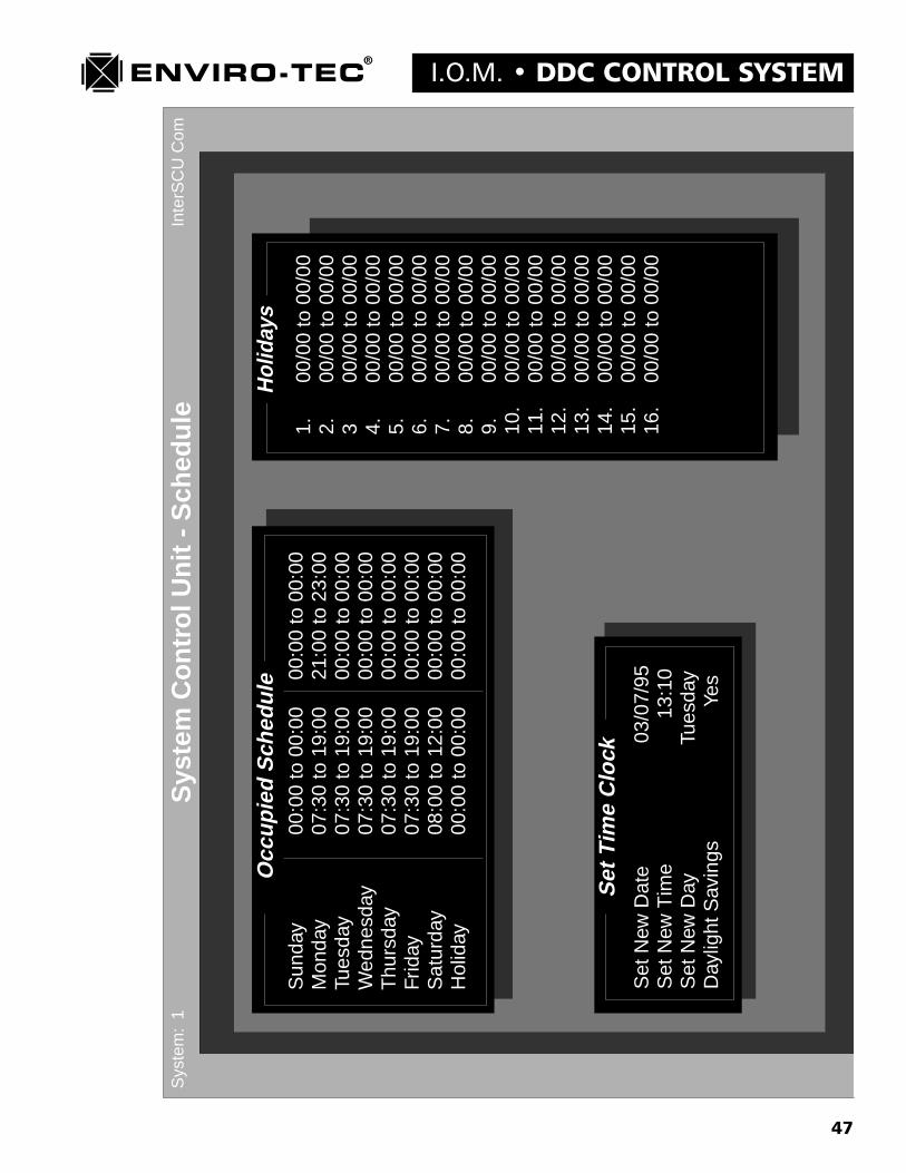
2. Scheduling (Current time and date information.)a. Date: Current date in day/month/year format.b. Time: Current time in 24 hour clock format.c. Day: Current day of week in Sunday through Saturday format.
3. Cycle Timers (Mode of operation timer information.)a. Cooling to Heating: Ventilation cycle time remaining in change from cooling to heating.b. Heating: Heating cycle time remaining till mode change decision is made.c. Heating to Cooling: Ventilation cycle time remaining in change from heating to cooling.d. Cooling: Cooling cycle time remaining till mode change decision is made.
4. Air Temperature (System temperature information.)a. Discharge Temperature: Air handler unit discharge temperature in degrees F.b. Return Temperature: Optional air handler unit return air temperature in degrees F. If no
sensor is connected to this input, a series of asterisks will be displayed.c. Outside Temperature: Optional outside air temperature in degrees F. If no sensor is
connected to this input, a series of asterisks will be displayed.
5. Output Control (System mode and SCU output status.)a. Operation Mode: Occupied or Unoccupied, Cooling or Heating or Ventilation or Standby.b. AHU Relay Control: SCU dry contact status. 1. Left column displays output relay assignments. 2. Center column displays output relay status. 3. Right column displays anti-cycle timer status of output relay.
47
I.O.M. � DDC CONTROL SYSTEM
Sys
tem
Co
ntr
ol U
nit
- S
ched
ule
Inte
rSC
UC
omS
yste
m:
1
Sun
day
00:0
0 to
00:
0000
:00
to 0
0:00
Mon
day
07:3
0 to
19:
0021
:00
to 2
3:00
Tues
day
07:3
0 to
19:
0000
:00
to 0
0:00
Wed
nesd
ay07
:30
to 1
9:00
00:0
0 to
00:
00T
hurs
day
07:3
0 to
19:
0000
:00
to 0
0:00
Frid
ay
07
:30
to 1
9:00
00:0
0 to
00:
00S
atur
day
08:0
0 to
12:
0000
:00
to 0
0:00
Hol
iday
00:0
0 to
00:
0000
:00
to 0
0:00
Set
New
Dat
e
03/0
7/95
Set
New
Tim
e
1
3:10
Set
New
Day
T
uesd
ayD
aylig
ht S
avin
gs
Ye
s
1.00
/00
to 0
0/00
2.00
/00
to 0
0/00
300
/00
to 0
0/00
4.00
/00
to 0
0/00
5.00
/00
to 0
0/00
6.00
/00
to 0
0/00
7.00
/00
to 0
0/00
8.00
/00
to 0
0/00
9.00
/00
to 0
0/00
10.
00/0
0 to
00/
0011
.00
/00
to 0
0/00
12.
00/0
0 to
00/
0013
.00
/00
to 0
0/00
14.
00/0
0 to
00/
0015
.00
/00
to 0
0/00
16.
00/0
0 to
00/
00
Occ
up
ied
Sch
edu
leH
olid
ays
Set
Tim
eC
lock

48
DDC CONTROL SYSTEM � I.O.M.�System Control Unit - Schedule� Screen
(see previous page for screen example)
The System Control Unit - Schedule screen is utilized to set up the daily occupied scheduling, the holiday periodscheduling, as well as the time of day, date, day of week and daylight saving time compensation option. See samplescreen displayed on previous page. There are 3 set up blocks within this screen to handle the above function.
1. Occupied Schedule (Daily system occupied times.)a. Left column displays day of week and holiday designation. The holiday designation applies to all
holiday periods assigned in the �Holidays� block to the right.b. Center column displays the first available daily occupied mode. From and to occupied times must
be set in 24 hour clock format. If no occupied period is desired, use the �00:00 to 00:00� formatentry.
c. Right column displays the second available daily occupied mode. From and to occupiedtimes must be set in 24 hour clock format. If no occupied period is desired, use the �00:00 to00:00� format entry.
2. Set Time Clock (System clock/calendar)a. Set New Date: Set current date using a day/month/year format.b. Set New Time: With �Daylight Savings Time� set to �No�, enter current, standard time in 24 hour
clock format.c. Set new Day: With the spacebar, toggle through choices till current day of week appears.d. Daylight Savings: With spacebar toggle to �Yes� or �No� option. When set to �Yes�, the internal
calendar will automatically compensate for seasonal changes into and out of daylight savingstime.
3. Holidays (Alternate holiday period scheduling.)a. Left column displays holiday number. 16 different holiday periods are available.b. Right column allows entry of specific holiday period in day/month format.
49
I.O.M. � DDC CONTROL SYSTEM
50
DDC CONTROL SYSTEM � I.O.M.�System Control Unit - Auxiliary Schedule� Screen
(see previous page for screen example)
The System Control Unit - Auxiliary Schedule screen is utilized to set up the daily operation of any SCU output relaysdefined as Auxiliary 1, 2 or 3. These schedules may or may not be different from the standard system occupied schedule.These auxiliary output relays may be used to control any system external device that will respond to a dry contactclosure. Enviro-Tec will not accept any responsibility for the operation of any such device as the auxiliary output relayis merely performing an external timeclock function. See sample screen displayed on previous page. There are 2 setupblocks within this screen to handle the above functions.
1. Auxiliary Output Scheduling (Daily auxiliary output relay scheduling.)a. Left column displays day of week and Alternate designation. The alternate designation applies to all
alternate periods assigned in the �Alternate Days� block for that auxiliary output relay.b. Aux1 column displays the from and to daily on time schedule for auxiliary control relay number 1.
From and to on times must be set in 24 hour clock format. If no on time is desired, use the �00:00to 00:00� format entry.
c. Aux2 column displays the from and to daily on time schedule for auxiliary control relay number 2.From and to on times must be set in 24 hour clock format. If no on time is desired, use the �00:00 to00:00� format entry.
d. Aux3 column displays the from and to daily on time schedule for auxiliary control relay number 3.From and to on times must be set in 24 hour clock format. If no on time is desired, use the �00:00 to00:00� format entry.
2. Alternate Days (Alternate day period auxiliary output relay operation.)a. Left column displays alternate day period number. There are 8 alternate schedules available.b. The 3 alternate day columns correspond with the 3 individual auxiliary output relay time schedules.
The alternate day periods allow for alternate on time operation of the specific output relays.Alternate day periods must be entered in day/month format.
c. The bottom line of the alternate days block allows for 2 separate options. These options may beselected by toggling the spacebar.1. Schedule: The auxiliary output relay will be on during schedule time only.2. Plus Override: The auxiliary output relay will be on during schedule time and any user initiated
unoccupied override time.
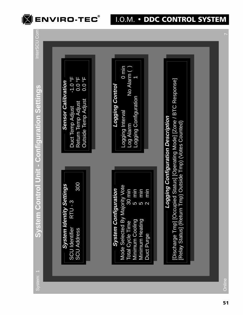
51
I.O.M. � DDC CONTROL SYSTEM
Inte
rSC
UC
om 7O
nlin
e
Sys
tem
Co
ntr
ol U
nit
- C
on
fig
ura
tio
n S
etti
ng
sS
yste
m:
1
Sys
tem
Iden
tity
Set
tin
gs
Sen
sor
Cal
ibra
tio
n
Sys
tem
Co
nfi
gu
rati
on
Lo
ggin
gC
on
tro
l
SC
U Id
entif
ier
RT
U -
3S
CU
Add
ress
300
Mod
e S
elec
ted
By
Maj
ority
Vot
eTo
tal C
ycle
Tim
e30
min
Min
imum
Coo
ling
5 m
inM
inim
um H
eatin
g5
min
Duc
t Pur
ge2
min
Duc
t Tem
p A
djus
t-1
.0 °
FR
etur
n Te
mp
Adj
ust
0.0
°FO
utsi
de T
emp
Adj
ust
0.0
°F
Logg
ing
Inte
rval
0 m
inLo
g A
larm
No
Ala
rm (
)Lo
ggin
g C
onfig
urat
ion
1
[Dis
char
ge T
mp]
[Occ
upie
d S
tatu
s] [O
pera
ting
Mod
e] [Z
one
/ BT
C R
espo
nse]
[Rel
ay S
tatu
s] (
Ret
urn
Tm
p) O
utsi
de T
mp)
(V
otes
Cou
nted
)
Lo
ggin
gC
on
fig
ura
tio
nD
escr
ipti
on
52
DDC CONTROL SYSTEM � I.O.M.�System Control Unit - Configuration Settings� Screen
(see previous page for screen example)
The System Control Unit - Configuration Settings screen is utilized to configure the operating parameters of the systemcontrol unit itself. See sample screen displayed on previous page. There are 5 setup blocks within this screen to handlethe following functions.
1. System Identity Settings (System name and address.)a. SCU Identifier: A name or designation given to the specific SCU that may consist of up to 16
alphanumeric characters. This identifier will appear on the ETI DDC Network screen.b. SCU Address: System unit address given to a specific SCU between 0 and 9900, in increments of
100.
2. System Configuration (SCU control mode and timing functions)a. Mode Selected By: There are 2 options which may be toggled by the space bar for this
selection:1. Majority Vote: When the current cycle timer (System Control Unit - Monitor screen)
counts down to 0, the controller will look at the results of the last polling to determine thenext control mode based on the majority of votes. If there are no heating or cooling votespresent, the controller will assume that all of the VAV terminal temperature setpoints aresatisfied and switch to the ventilation mode.
2. Time Cycling: This option applies the percentage of cooling and heating demand to a fixedtime cycle. When the current total cycle timers (Both heating and cooling cycle timers)count down to 0, the controller looks at the results of the last polling. The total number of votesis broken down into percentage of cooling and percentage of heating demand. Thosepercentages are then applied to the Total Cycle Time. Heating will be the active mode first.When that mode time cycle has counted down to 0, the smaller of the 2 will become active.When this cycle time has counted down to 0, the entire process restarts.
b. Total Cycle Time: Used only when the �Time Cycling� option above is selected.c. Minimum Cooling: Minimum cooling cycle time before controller looks at results of most recent
polling and decides whether to stay in cooling or change modes. Majority vote option only. Intime cycling, set to zero.
d. Minimum Heating: Minimum heating cycle time before controller looks at results of most recentpolling and decides whether to stay in heating or change modes. Majority vote option only. Intime cycling, set to zero.
e. Duct Purge: Ventilation time between cooling and heating mode changes. Applies to bothoptions.
3. Sensor Calibration (Temperature sensor calibration adjustments.)a. Duct Temp Adjust: Air handler discharge temperature sensor calibration adjustment. Add
or subtract the number of degrees and/or tenths of degrees required to adjust the temperaturereading to match that of a calibrated device. If subtracting a value, enter the minus sign afterentering the numeric value.
b. Return Temp Adjust: Air handler return temperature sensor (optional) calibration adjustment.Add or subtract the number of degrees and/or tenths of degrees required to adjust the temperaturereading to match that of a calibrated device. If subtracting a value, enter the minus sign afterentering the numeric value.
c. Outside Temp Adjust: Outside air temperature sensor (optional) calibration adjustment. Add orsubtract the number of degrees and/or tenths of degrees required to adjust the temperaturereading to match that of a calibrated device. If subtracting a value, enter the minus sign afterentering the numeric value.

53
I.O.M. � DDC CONTROL SYSTEM
4. Logging Control (Logging and Trending program setup)a. This setup block will be discussed in a separate logging and trending program manual.
5. Logging Configuration Description (Logging and Trending program configuration.)a. This configuration block will be discussed in a separate logging and trending program manual.

54
DDC CONTROL SYSTEM � I.O.M.In
terS
CU
Com 39
Onl
ine
Sys
tem
Co
ntr
ol U
nit
-A
HU
Co
ntr
ol S
etti
ng
sS
yste
m:1
Valv
eM
odul
atio
nC
ontr
olC
oo
ling
Sta
ge
Co
ntr
ol
Rel
ayO
utpu
tMap
ping
/Ant
icyc
les
Hea
ting
Sta
geC
ontr
ol
Coo
ling
Ful
ly O
n A
bove
70.0
°F
Coo
ling
Ful
ly O
ff B
elow
50.0
°F
Hea
ting
Ful
ly O
ff A
bove
1
20.0
°F
Hea
ting
Ful
ly O
n B
elow
90.0
°F
----
Coo
ling
Thr
ottle
Ran
ge:A
01--
--F
ull O
n 10
Vol
t Ful
l Off
0 V
olt
---H
eatin
g T
hrot
tle R
ange
:A
02 -
--F
ull O
n 10
Vol
t Ful
l Off
0 V
olt
1.Fa
n0
sec
2.C
oolin
g 1
300
sec
3.C
oolin
g 2
300
sec
4.H
eatin
g 1
30 s
ec5.
Hea
ting
230
sec
6.A
uxili
ary
10
sec
7.A
uxili
ary
20
sec
8.C
hang
eove
r0
sec
On
Bel
ow
Off
Abo
veH
eatin
g 1
110.
0 °F
120.
0 °F
Hea
ting
2
10
5.0
°F11
5.0
°FH
eatin
g 3
0
.0 °
F0.
0 °F
Hea
ting
4
0.0
°F
0.0
°FH
eatin
g 5
0
.0 °
F0.
0 °F
Hea
ting
6
0.0
°F
0.0
°FH
eatin
g 7
0
.0 °
F0.
0 °F
Off
Bel
owO
n A
bove
Coo
ling
1
5
1.0
°F59
.0 °
FC
oolin
g 2
56.
0 °F
64.0
°F
Coo
ling
3
0.0
°F
0.0
°FC
oolin
g 4
0
.0 °
F0.
0 °F
Coo
ling
5
0.0
°F
0.0
°FC
oolin
g 6
0
.0 °
F0.
0 °F
Coo
ling
7
0.0
°F
0.0
°F
55
I.O.M. � DDC CONTROL SYSTEM
�System Control Unit - AHU Control Settings� Screen
The System Control Unit - AHU Control Settings screen is utilized to configure the output parameters to the Air Han-dling Unit from the SCU. See sample screen displayed on previous page. There are 4 setup blocks within this screen tohandle the following functions.
1. Valve Modulation Control (Modulating valve control on SCUA4A2 and SCULT4 only.)a. Cooling Fully On Above: Chilled water valve output at designated fully on voltage when air handler
discharge temperature is greater than or equal to this value in degrees F and system is in cooling mode.Total output voltage range is 0 to 10 VDC.
b. Cooling Fully Off Below: Chilled water valve output at designated fully off voltage when air handlerdischarge temperature is less than or equal to this value in degrees F and system is in cooling mode.Total output voltage range is 0 to 10 VDC.
c. Heating Fully Off Above: Hot water valve output at designated fully off voltage when air handlerdischarge temperature is greater than or equal to this value in degrees F and the system is in heatingmode. Total output voltage range is 0 to 10 VDC.
d. Heating Fully On Below: Hot water valve output at designated fully on voltage when air handlerdischarge temperature is less than or equal to this value in degrees F and the system is in heating mode.Total output voltage range is 0 to 10 VDC.
e. AO1 assignment: AO1 or Analog Output 1 may be assigned as either a Cooling or Heating valveoutput. This selection can be made by toggling the space bar.
f. AO1 Throttling Range: This allows the output voltage range of the analog output to be configured tomatch the throttling range of the modulating valve being used. Full On Volts and Full Off Volts can beset by toggling the spacebar to increment the selection by 1 VDC intervals.
g. AO2 assignment: AO2 or Analog Output 2 may be assigned as either a Cooling or Heating valveoutput. This selection can be made by toggling the space bar.
h. AO2 Throttling Range: This allows the output voltage range of the analog output to be configured tomatch the throttling range of the modulating valve being used. Full On Volts and Full Off Volts can beset by toggling the spacebar to increment the selection by 1 VDC intervals.
2. Relay Output Mapping / Anticycles (Output relay and anticycle configuration.)a. Left column indicates the output relay number assignment.b. Center column allows for the �Mapping� or assignment of the function of the relay. One of 19
different functions may be assigned to each relay. The relay assignment is accomplished by togglingthe spacebar till the desired function appears. The 19 options are:1. Fan: Air handler unit fan control.2. Changeover: Water source heat pump changeover valve control. Relay is active in cooling
mode.3. Cooling 1 thru Cooling 7: Cooling mode has 7 possible stages of control.4. Heating 1 thru Heating 7: Heating mode has 7 possible stages of control.5. Auxiliary 1 thru Auxiliary 3: There are 3 possible auxiliary contacts.
c. Right column allows for an �Anticycle� time to be assigned to each output relay individually asrequired. An anticycle time is the amount of time a relay will be held inactive after it has received anoff command from the controller. The primary purpose of this function is to prevent the short cyclingof whatever equipment is being controlled by the individual output relay. The most common use of thisfunction is to keep from short cycling compressors.

56
DDC CONTROL SYSTEM � I.O.M.
3. Cooling Stage Control (Discharge temperature control of the cooling stages.)a. Left column indicates cooling stage number assignment.b. �Off Below� column allows the turn off discharge temperature for the different cooling stages tobe
configured.c. �On Above: column allows the turn on discharge temperature for the different cooling stages tobe
configured.
4. Heating Stage Control (Discharge temperature control of the heating stages.)a. Left column indicates heating stage number assignment.b. �On Below� column allows the turn on discharge temperature for the different heating stages to be
configured.c. �Off Above: column allows the turn off discharge temperature for the different heating stages tobe
configured.

57
I.O.M. � DDC CONTROL SYSTEM
27O
nlin
e
Sta
tic P
ress
ure
Mon
itor
& C
onfig
urat
ion
Set
tings
Sys
tem
:3
Pre
ssur
eS
enso
rS
tatic
Pre
ssur
e1.
18 in
wg
Con
trol
Set
tings
Iden
tifie
rE
ngin
eerin
g B
TC
Uni
t Add
ress
365
Byp
ass
Pre
ssur
e S
etpo
int
1.2
0 in
wg
Byp
ass
Pre
ssur
e D
eadb
and
0.05
in w
gD
ampe
r M
odul
atio
n B
and
0.10
in w
gV
FD
Pre
ssur
e S
etpo
int
1.00
in w
gV
FD
Pre
ssur
e D
eadb
and
0.05
in w
gP
ress
ure
Offs
et A
djus
t0.
00 in
wg
Pre
ssur
e S
lope
Adj
ust
0.00
in w
gV
FD
full
scal
e re
spon
se ti
me
2 m
in
Logg
ing
Inte
rval
1 m
inLo
g A
larm
No
Ala
rm (
)
Logg
ing
Con
trol
58
DDC CONTROL SYSTEM � I.O.M.
�Pressure Sensor Monitor & Configuration Settings� Screen(see previous page for screen example)
The Pressure Sensor Monitor & Configuration Settings screen allows for the configuration of all duct static pressurecontrol parameters. This screen also allows for the real time monitoring of the current system duct static pressure. Seesample screen on previous page. There is 1 monitor block and 1 setup block within this screen to handle the followingfunctions.
1. Pressure Sensora. Static Pressure: Real time system duct static pressure update in inches of water.
2. Control Settings (Static pressure control parameters.)a. Identifier: A name or designation given to the specific BTC that may consist of up to 16 alphanu-
meric characters. The first of the characters entered must be an alpha character. This identifierwillappear on the ETI DDC Network screen.
b. Unit Address: Since the BTC address will always be 65 on any of the 100 possible systems, onlythe system number in front of the 65 will change. 165, 365,2465, etc.
c. Bypass Pressure Setpoint: Desired system duct static pressure setpoint down to hundreds of aninch of water to be controlled by up to 3 bypass terminals.
d. Bypass Pressure Deadband: A control range above and below the pressure setpoint where thecontroller is satisfied with the actual static pressure. As shown in the sample screen, with apressure setpoint of 1.25 in. wg. and a deadband of .02 in. wg., the controller would besatisfied with an actual static pressure range of between 1.23 in. wg. and 1.27 in.wg.
e. Damper Modulation Band: Since the ETI DDC control system uses a damper actuator controlmethod called �pulse width modulation�, some form of pulse output control to the damperactuator is required. Pulse width modulation simply means that the closer to the setpointvalue the actual value becomes, the shorter the output pulses to damper actuator become. Thedamper modulation band tells the controller how close to setpoint the pressure needs to bebefore switching from continuous to pulse width modulation operation.
f. VFD (Variable Frequency Drive) Pressure Setpoint: Desired system duct static pressure setpointdown to hundreds of an inch of water to be controlled by a 0 - 10 VDC modulating output to a VFD.
g. VFD (Variable Frequency Drive) Pressure Deadband: A control range above and below thepressure setpoint where the controller is satisfied with the actual static pressure. As shown in thesample screen, with a pressure setpoint of 1.25 in. wg. and a deadband of .02 in. wg., thecontroller would be satisfied with an actual static pressure range of between 1.23 in. wg. and 1.27in.wg.
h. Pressure Offset Adjust: The ability to calibrate the starting point of the static pressure curve. Theoffset is the software equivalent of an electronic Zero adjust.
i. Pressure Slope Adjust: The ability to calibrate the slope of the static pressure curve. The slope isthe software equivalent of an electronic Gain adjust.
j. VFD full scale response time: When utilizing the modulating 0 VDC thru 10 VDC output tocontrol a frequency drive or inlet vanes on an air handler fan, The VFD full scale response timemay be adjusted to between 20 seconds and 2 minutes. This simply states the shortest amount oftime that the controller will allow the output signal to ramp from 0 VDC to 10 VDC.
3. Logging Control (Logging and Trending program configuration.)a. This configuration block will be discussed in a separate logging and trending program manual.
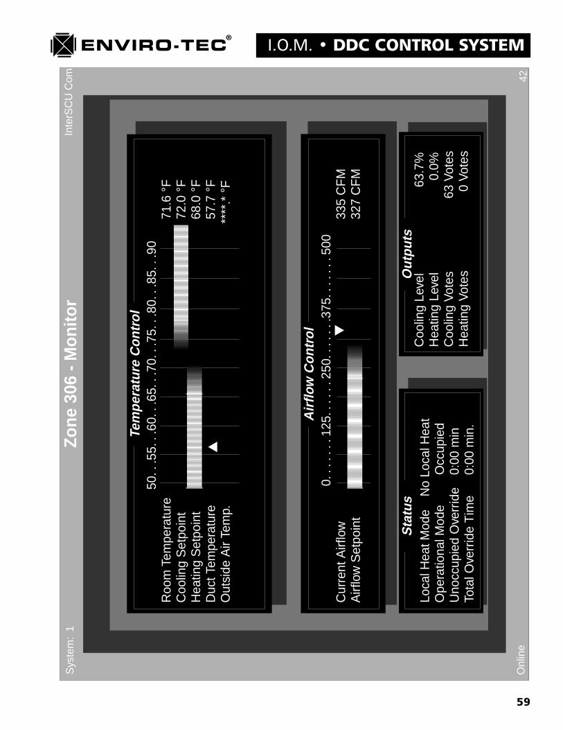
59
I.O.M. � DDC CONTROL SYSTEMIn
terS
CU
Com 42
Onl
ine
Zone
306
- M
onito
rS
yste
m:
1
Tem
pera
ture
Con
trol
Air
flow
Con
trol
Sta
tus
Out
puts
50..
.55.
..60
...6
5...
70..
.75.
..80
...8
5...
90R
oom
Tem
pera
ture
71.6
°F
Coo
ling
Set
poin
t72
.0 °
FH
eatin
g S
etpo
int
68.0
°F
Duc
t Tem
pera
ture
57.7
°F
Out
side
Air
Tem
p.**
**.*
°F
0...
....
125.
....
.250
....
...3
75..
....
.500
Cur
rent
Airf
low
335
CF
MA
irflo
w S
etpo
int
327
CF
M
Loca
l Hea
t Mod
eN
o Lo
cal H
eat
Ope
ratio
nal M
ode
Occ
upie
dU
nocc
upie
d O
verr
ide
0:00
min
Tota
l Ove
rrid
e T
ime
0:00
min
.
Coo
ling
Leve
l63
.7%
Hea
ting
Leve
l0.
0%C
oolin
g Vo
tes
63 V
otes
Hea
ting
Vote
s0
Vote
s

60
DDC CONTROL SYSTEM � I.O.M.�Zone (Address) - Monitor� Screen
(see pages 59 and 61 for screen examples)The Zone - Monitor screen displays all current operating information related to the VAV zone terminal. See the samplescreen displayed on the previous page. Some of this information is displayed in graphical form with different colorsrepresenting various parameters. None of the data or setpoints on this screen can be altered by the operator with theexception of the �Total Override Time�. Any setpoint or parameter changes must be made in subsequent screens. Thereare 4 information blocks within this screen. The information in each block updates in real time as quickly as thecomputer running the VTMON program will allow.
1. Temperature Control (Actual and setpoint temperature data displayed in degrees F.)a. Room Temperature: Current VAV zone terminal thermostat temperatureb. Cooling Setpoint: Current VAV zone terminal cooling setpoint. This setpoint may have been
established either at the thermostat or through the software.c. Heating Setpoint: Current VAV zone terminal heating setpoint. This setpoint may have been
established either at the thermostat or through the software.d. Duct Temperature: Current VAV zone terminal inlet duct temperature.e. Outside Air Temp: If the optional outside air temperature sensor is being utilized at the SCU, this
data is sent down the network during the polling process and displayed here. If the optionaloutside air temperature sensor is not used at the SCU. a series of asterisks will be displayedhere.
2. Airflow Controla. CFM scale: This scale reflects the range in CFM between the minimum and maximum
allowable CFM setpoints entered into the individual VAV zone terminal controller.b. Current Airflow: Actual primary airflow through the VAV zone terminal in CFM.c. Airflow Setpoint: Current airflow setpoint for the individual VAV zone terminal determined by
the PID algorithm based on current temperature demand.
3. Status (Current mode and timer status.)a. Local Heat Mode: Current status of VAV zone terminal controlled heat if any.b. Operational Mode: Current mode status, either Occupied, Unoccupied or Override.c. Unoccupied Override: Countdown timer showing time till VAV zone terminal controller switches
from unoccupied override to unoccupied mode. This timer becomes active when the �On�button is pushed on the thermostat when the system is in the unoccupied mode.
d. Total Override Time: This register accumulates the total amount of time that the VAV zoneterminal has been in unoccupied override mode. This information is generally used to chargetenants for excess energy usage. The time in the register can be reset to 0 by using the �Ctrl C�command. See the sample screen on next page.
4. Outputs (Current PID algorithm output status.)a. Cooling Level: Percentage of output determined by the PID algorithm based on temperature
demand in the current occupied or unoccupied cooling mode.b. Heating Level: Percentage of output determined by the PID algorithm based on temperature
demand in the current occupied or unoccupied heating mode.c. Cooling Votes: Number of individual VAV zone terminal cooling votes being sent to the SCU
during polling. This number is determined by the controller applying the cooling level percentageto the total number of votes that the terminal has been configured with in the current occupied orunoccupied cooling mode.
d. Heating Votes: Number of individual VAV zone terminal heating votes being sent to the SCUduring polling. This number is determined by the controller applying the heating level percentageto the total number of votes that the terminal has been configured with in the current occupied orunoccupied heating mode.
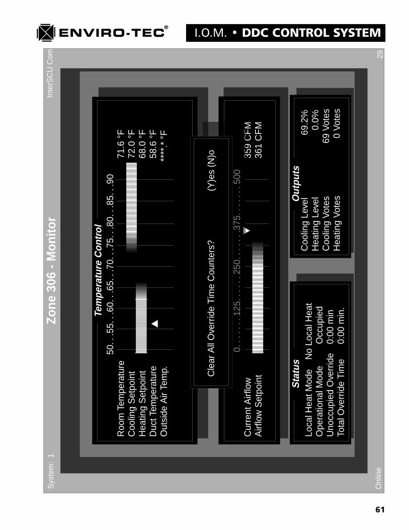
61
I.O.M. � DDC CONTROL SYSTEMIn
terS
CU
Com 29
Onl
ine
Zone
306
- M
onito
rS
yste
m:
1
Tem
pera
ture
Con
trol
Air
flow
Con
trol
Sta
tus
Out
puts
50..
.55.
..60
...6
5...
70..
.75.
..80
...8
5...
90R
oom
Tem
pera
ture
71.6
°F
Coo
ling
Set
poin
t72
.0 °
FH
eatin
g S
etpo
int
68.0
°F
Duc
t Tem
pera
ture
58.6
°F
Out
side
Air
Tem
p.**
**.*
°F
0...
....
125.
....
.250
....
...3
75..
....
.500
Cur
rent
Airf
low
359
CF
MA
irflo
w S
etpo
int
361
CF
M
Loca
l Hea
t Mod
eN
o Lo
cal H
eat
Ope
ratio
nal M
ode
Occ
upie
dU
nocc
upie
d O
verr
ide
0:00
min
Tota
l Ove
rrid
e T
ime
0:00
min
.
Coo
ling
Leve
l69
.2%
Hea
ting
Leve
l0.
0%C
oolin
g Vo
tes
69 V
otes
Hea
ting
Vote
s0
Vote
s
Air
flow
Con
trol
0...
....
125.
....
.250
....
...3
75..
....
.500
359
CF
M
Cle
ar A
ll O
verr
ide
Tim
e C
ount
ers?
(Y)e
s (N
)o
62
DDC CONTROL SYSTEM � I.O.M.
19O
nlin
e
ZON
E 3
06 -
Use
r S
ettin
gsS
yste
m:
1
Uni
tIde
ntity
Set
tings
Ther
mos
tatS
ettin
gs
Zon
e Id
entif
ier
JER
RY
'S O
FF
ICE
Zon
e A
ddre
ss30
6
Lock
Set
poin
ts?
No
Lock
ed S
tat
Coo
ling
Set
poin
t74
°F
Hea
ting
Set
poin
t70
°F
Coo
ling
Set
poin
t90
°F
Hea
ting
Set
poin
t50
°F
Ove
rrid
e T
ime
30 m
in.
Uno
ccup
ied
Mod
e

63
I.O.M. � DDC CONTROL SYSTEM�Zone (Address) - User Settings� Screen
The Zone - User Settings screen allows identifier, address and temperature setpoint configuration. See the sample screenon the previous page. There are 2 setup blocks within this screen to handle the following functions.
1. Unit Identity Settings (VAV zone terminal name and address.)a. Identifier: A name or designation given to the specific VAV zone terminal that may consist of up to
16 alphanumeric characters. The first of the characters entered must be an alpha character. Thisidentifier will appear on the ETI DDC Network screen.
b. Unit Address: An address of between 1 and 64 must be assigned to the VAV zone terminal.No. 2 terminals on the zone bus network may have the same address. The system number must beentered in front of the address unless the system number is 0.
2. Thermostat Settingsa. Lock Setpoints: This option allows for the cooling and heating setpoints to be locked. The yes and
no options can be toggled with the spacebar.b. Locked Stat Cooling Setpoint and Heating Setpoint: These setpoint parameters will be cooling and
heating setpoints if the Lock Setpoints option is set to yes.
3. Unoccupied Modea. Cooling Setpoint: The cooling setpoint will change to this value when the system switches
into unoccupied mode.b. Heating Setpoint: The heating setpoint will change to this value when the system switches
into unoccupied mode.c. Override Time: This is the amount of time in minutes that the VAV zone terminal will put
the system into unoccupied override when the On button is pressed at the thermostat. The realtime counter may be monitored on the Zone - Monitor screen.
64
DDC CONTROL SYSTEM � I.O.M.In
terS
CU
Com
Rea
d:14
86E
roor
:0
%E
rror
:0.
0%36
Onl
ine
Zone
504
- G
ener
al C
onfig
urat
ion
Set
tings
Sys
tem
:1
Air
flow
Con
trol
Ther
mos
tatC
ontr
olC
oolin
g M
axim
um80
0 C
FM
Coo
ling
Min
imum
50 C
FM
Hea
ting
Max
imum
1250
CF
MH
eatin
g M
inim
um20
0 C
FM
War
mU
p M
axim
um
125
0 C
FM
War
mU
p M
inim
um
2
00 C
FM
Loca
l Hea
t FLo
w10
00 C
FM
Dea
dban
d40
CF
MM
odul
atio
n B
and
175
CF
M
Max
imum
Set
poin
t Allo
wed
80.0
°F
Min
imum
Set
poin
t A
llow
ed65
.0 °
F
Coo
ling
Set
poin
t Offs
et2.
0 °F
Hea
ting
Set
poin
tO
ffset
2.0
°F
Min
imum
Dea
dban
d4.
0 °F
Dis
play
ed T
emp
Adj
ust
0.0
°F
Logg
ing
Inte
rval
1 m
inLo
g A
larm
No
Ala
rm (
)
Occ
upie
d C
oolin
g10
0 Vo
tes
Occ
upie
d H
eatin
g10
0 Vo
tes
Uno
ccup
ied
Coo
ling
100
Vote
sU
nocc
upie
d H
eatin
g10
0 Vo
tes
Logg
ing
Con
trol
Max
imum
Vote
s
Dam
per
Con
trol
Reg
ular
Ther
mos
tat
Dis
play
Ther
mos
tat
65
I.O.M. � DDC CONTROL SYSTEM�Zone (Address) - General Configuration Settings� Screen
The Zone - General Configuration Settings screen allows for the adjustment of the parameters which control the VAVzone terminal limits. See the sample screen on the previous page. There are 4 setup blocks within this screen to handlethe following functions.
1. Airflow Control (Individual mode specified CFM setpoint limits.)a. Cooling Maximum: Maximum allowable specified CFM setpoint for cooling mode.b. Cooling Minimum: Minimum allowable specified CFM setpoint for cooling mode.c. Heating Maximum: Maximum allowable specified CFM setpoint for heating mode.d. Heating Minimum: Minimum allowable specified CFM setpoint for heating mode.e. Warm Up Maximum: Maximum allowable specified CFM setpoint for warm-up mode.
(Future option)f. Warm Up Minimum: Minimum allowable specified CFM setpoint for warm-up mode.
(Future option)g. Local Heat Flow: For a VAV zone terminal that is equipped with it�s own local heating capability.
When the zone demand is for heat and the primary inlet air temperature is lower than the heatingsetpoint, the local heat flow value will become the CFM setpoint.
2. Damper Controla. Deadband: A control range above and below the CFM setpoint where the controller is satisfied
with the actual CFM. As shown in the Zone - Monitor sample screen, with a setpoint of 327CFM and a deadband of 40 CFM, the controller would be satisfied with an actual CFM range ofbetween 287 CFM and 367 CFM. See table 5-1 for recommended deadband settings per terminalsize.
b. Modulation Band: Since the ETI DDC control system uses a damper actuator control methodcalled �pulse width modulation,� some form of pulse output control to the damper actuator isrequired. Pulse width modulation simply means that the closer to the setpoint value the actualvalue becomes, the shorter the output pulses to damper actuator become. The damper modulationband tells the controller how close to CFM setpoint the actual CFM needs to be before switch-ing from continuous to pulse width modulation operation. See table 5-1 for recommendedmodulation band settings per terminal size.
Table 5-1
Terminal Minimum Maximum Deadband Modulation Size CFM CFM CFM Band
4 35 225 25 100 5 55 350 30 150 6 65 550 40 175 8 120 1000 50 200 10 195 1600 60 300 12 280 2300 70 350 14 400 3100 75 400 16 550 4100 100 500
Note* Maximum and Minimum CFM�s listed in table 5-1 are recommended absolute VAV terminal limits. These valueswill probably not reflect the design CFM flows on a specific installation.

66
DDC CONTROL SYSTEM � I.O.M.3. Logging Control (Logging and Trending program configuration.)
a. This configuration block will be discussed in a separate logging and trending program manual.
4. Thermostat Control (Thermostat setpoint range limitations.)a. Maximum Setpoint Allowed: Maximum cooling setpoint that the VAV zone terminal controller
will recognize regardless of actual thermostat setting.b. Minimum Setpoint Allowed: Minimum heating setpoint that the VAV zone terminal controller
will recognize regardless of actual thermostat setting.
5. Regulate Thermostat (Establish cooling/heating deadband for use with ETTS thermostat.)a. Cooling Setpoint Offset: Number of degrees F above the thumbwheel setpoint on the thermostat
that will be designated as the controller cooling setpoint.b. Heating Setpoint Offset: Number of degrees F below the thumbwheel setpoint on the thermostat
that will be designated as the controller heating setpoint.
6. Display Thermostat (ETDIS thermostat.)a. Minimum Deadband: Minimum allowable deadband between cooling and heating setpoint. Should
the displayed heating setpoint on the ETDIS thermostat be set closer to the cooling setpoint thanthis deadband value, the cooling setpoint will become the master and subtract the deadbandvalue from itself to establish a new heating setpoint. Recommended deadband is 3 or 4degrees F.
b. Displayed Temp Adjust: This option gives the ability to alter the room temperature display at theETDIS display thermostat only. The temperature display may be altered by a positive or negativeentry in degrees F.
7. Maximum Votes (Mode/terminal priority capability.)a. Each VAV zone terminal has the capability of being assigned an operating priority in comparison
to the other VAV zone terminals on the same system. This is accomplished by assigning �Votes� toeach terminal in each of the 4 operating modes. Each terminal controller has the capability of beingprogrammed with anywhere between 0 and 255 votes in each or these operating modes. The morevotes a terminal controller is assigned in a particular mode, the more capability it has to influencethe SCU as to which mode will be chosen when the decision is made.
67
I.O.M. � DDC CONTROL SYSTEMIn
terS
CU
Com 40
Onl
ine
Zone
306
- Lo
w L
evel
Con
figur
atio
n S
ettin
gsS
yste
m:1
Box
Con
figur
atio
nO
utpu
tCon
trol
Mod
e C
ontr
ol U
se S
CU
Sch
edul
ing
Box
Typ
eS
DV
945-
Sta
ndar
dB
ox S
ize
6 in
ches
Airf
low
Slo
pe0.
00 %
Airf
low
Offs
et0
CF
MS
pace
Tem
p A
djus
t0.
0 °
FD
uct T
emp
Adj
ust
0.0
°F
Tem
p S
etpo
int A
djus
t0.
0 °
F
On
Off
Fan
1.0
°F0.
5 °F
Hea
t 12.
0 °F
0.5
°FH
eat 2
3.0
°F1.
0 °F
Hea
t 30.
0 °F
0.0
°FFa
n10
000
CF
M0
CF
MD
uct T
emp
Cut
off
90.0
°F
----
----
---F
loat
ing
Poi
nt M
odul
atio
n---
----
---
Sta
rt O
ffset
1.0
°FT
hrot
tling
Ran
ge3.
0 °F
Valv
e F
ull S
trok
e12
0.0
sec
Valv
e M
in S
tep
5.0
sec
----
----
--P
ropo
rtio
nal M
odul
atio
n---
----
----
--S
tart
Offs
et1.
0 °F
Thr
ottli
ng R
ange
3.0
°F--
----
----
----
----
-Ana
log
Out
put-
----
----
----
---
Ful
l On
10
Vol
tF
ull O
ff 2
Vol
t
Kp
3
3.33
Ki
0.04
Kd
0
.00
Max
imum
Inte
gral
Val
ue
3
0000
PID
Tem
pera
ture
Con
trol
Sen
sor
Cal
ibra
tion
68
DDC CONTROL SYSTEM � I.O.M.�Zone (Address) - Low Level Configuration Settings� Screen
(see previous page for screen example)The Zone - Low Level Configuration Settings screen allows for the adjustment of parameters which control VAV zoneterminal inputs and outputs. See the sample screen on the previous page. There are 4 setup blocks within this screen tohandle the following functions.
1. Box Configuration (Defines VAV terminal type to controller.)a. Mode Control: This configuration determines which of the 3 currently available scheduling
options will be used. (A fourth auxiliary schedule routine will be available in the near future.)These options are selected by toggling the space bar.
1. Use SCU Scheduling: The VAV zone terminal controller will switch back and forth betweenoccupied and unoccupied modes in conjunction with the schedule that has been programmedinto the SCU schedule screen.
2. Stat ON/OFF Timer: The VAV zone terminal controller will respond only to the �ON�button located at the zone terminal thermostat. The VAV terminal will remain in the occupiedmode after the �ON� button is pressed for the amount of time programmed into the�Override Timer� option in the �Zone - User Settings� screen.
3. Stat ON/OFF Switch: The VAV zone terminal controller will toggle between it�s occupied andunoccupied setpoints each time the �ON� button located at the zone terminal thermostat ispressed.
b. Box Type: This configuration tells the controller exactly what type of VAV terminal it is installedon. These selections will tell the controller not only which type of terminal but which type oflocal heat capability, if any, the terminal has been equipped with. There are 13 different optionswhich may be selected by toggling the space bar.
1. SDV942 Standard: This option designates a single duct terminal with no local heatcapability using the ETDD0 controller board.
2. SDV945 No Local Reheat: This option designates a single duct terminal with no local heatcapability using the ETDD2F controller board. This controller is equipped to control localheat if the equipment is added at a later date.
3. SDV945 Staged Heat: This option designates a single duct terminal with either 1, 2 or 3stages of local electric heat or a stage of hot water heat using a N.C. spring returnvalve actuator.
4. SDV945 Tri-State Heat: This option designates a single duct terminal with a floating pointtype hot water valve.
5. SDV945 Proportional Heat: This option designates a single duct terminal with a modulating,proportional type hot water valve or SCR controlled electric heat.
6. FVV945 No Local Reheat: This option designates a parallel, variable volume, fan poweredterminal with no local heat capability using the ETDD2F controller board. This controller isequipped to control local heat if the equipment is added at a later date.
7. FVV945 Staged Heat: This option designates a parallel, variable volume, fan poweredterminal with either 1 or 2 stages of local electric heat or a stage of hot water heat using an N.C.spring return valve actuator.
8. FVV945 Tri-State Heat: This option designates a parallel, variable volume, fan poweredterminal with a floating point type hot water valve.
9. FVV945 Proportional Heat: This option designates a parallel, variable volume, fan poweredterminal with a modulating, proportional type hot water valve or SCR controlled electricheat.
10. FCV945 No Local Reheat: This option designates a series, constant volume, fan poweredterminal with no local heat capability using the ETDD2F controller board. This controller isequipped to control local heat if the equipment is added at a later date.
69
I.O.M. � DDC CONTROL SYSTEM11. FCV945 Staged Heat: This option designates a series, constant volume, fan powered
terminal with either 1 or 2 stages of local electric heat or a stage of hot water heat using an N.C.spring return valve actuator.
12. FCV945 Tri-State Heat: This option designates a series, constant volume, fan poweredterminal with a floating point type hot water valve.
13. FVV945 Proportional Heat: This option designates a series, constant volume, fan poweredterminal with a modulating, proportional type hot water valve or SCR controlled electricheat.
c. Box Size: This configuration tells the controller what size inlet the VAV zone terminal has. This isa most critical parameter for a pressure independent controller as the box size determines how thecontroller will convert the flow transducer information into actual CFM. This option isselected by toggling the space bar. Available sizes are 4, 5, 6, 8, 10, 12, 14, 16, 19 and 22.
2. Sensor Calibration (Analog input signal calibration.)a. Airflow Slope: This calibration parameter is the equivalent to an electronic �Gain� adjustment.
The unit of slope is percentage (%) and refers to the slope of the airflow curve (Chapter 4, dwg no.15883) for the VAV zone terminal box size. To enter a minus (-) value, enter the numericvalue, then press the minus (-) key to make the entry a negative number. Do not press the minus(-) key first. See chapter 7 for calibration instructions.
b. Airflow Offset: This calibration parameter is the equivalent to an electronic �Zero� adjustment.The units are in CFM and the entry will add to or delete from the actual CFM reading by thesame number. To delete from the actual reading, enter the numeric value, then press the minus (-)key to make the entry a negative number. Do not press the minus (-) key first. See chapter 7 forcalibration instructions.
c. Space Temp Adjust: This calibration parameter allows for the adjustment of the displayed spacetemperature to match that of a calibrated temperature measuring device. To delete from theactual reading, enter the numeric value, then press the minus (-) key to make the entry anegative number. Do not press the minus (-) key first.
d. Duct Temp Adjust: This calibration parameter allows for the adjustment of the displayed ducttemperature to match that of a calibrated temperature measuring device. To delete from theactual reading, enter the numeric value, then press the minus (-) key to make the entry anegative number. Do not press the minus (-) key first.
e. Temp Setpoint Adjust: For use with the ETTS regular thermostat only. This calibrationparameter allows for the adjustment of the displayed cooling and heating setpoint when theETTS thermostat is used to insure that the dial setpoint matches the display. To delete fromthe actual reading, enter the numeric value, then press the minus (-) key to make the entry anegative number. Do not press the minus (-) key first.
3. PID Temperature Control (Proportional, Integral and Derivative. Adjustment not advised.)a. Kp: This represents the proportional segment of the PID algorithm. The proportional finds the
difference between the actual space temperature and the setpoint. This difference is called the erroror offset.
b. Ki: This represents the integral segment of the PID algorithm. The integral determines how longthe offset has existed and forms an accumulated offset over time. This total offset over time iscalled the �integral sum�. This integral sum is updated over 30 second time periods.
c. Kd: This represents the derivative segment of the PID algorithm. The derivative determines therate at which the offset is changing.
d. Maximum Integral Value: This value represents the integral limit or ceiling that the PIDalgorithm will accept.
70
DDC CONTROL SYSTEM � I.O.M.4. Output Control (Local heat control parameters.)There are four sections to this setup block. The first deals with the �On� and Off� setpoints controlling the�Staged� outputs on the controller. The second deals with the operating parameters controlling a�Tri-State�, floating point hot water valve. The third deals with the operating parameters controlling eithera �Proportional�, modulating hot water valve or SCR controlled electric heat. The fourth sets the �FullOn� and �Full Off� DC voltage outputs within the 0 to 10 VDC range that the �Proportional� control iscapable of maintaining.
a. On - Off: The �On� column temperature parameters deal with the number of degrees and tenths ofdegrees F below heating setpoint that the specified output will become energized. The �Off�column temperature parameters deal with the number of degrees and tenths of degrees F belowheating setpoint that the specified output will become de-energized.
b. Fan: Used in conjunction with the �FVV945� box types. Designates the turn on and turn offspace temperature for the VAV zone terminal fan motor.
c. Heat 1: Used in conjunction with any �Staged Heat� box type. Designates the turn on and turn offspace temperature for the first stage of VAV zone terminal local heat.
d. Heat 2: Used in conjunction with any �Staged Heat� box type. Designates the turn on and turn offspace temperature for the second stage of VAV zone terminal local heat.
e. Heat 3: (Special order only) Used in conjunction with any �Staged Heat� box type. Designates theturn on and turn off space temperature for the second stage of VAV zone terminal local heat.
f. Fan: (Optional) Used in conjunction with the �FVV945� box types. Designates the turn on andturn off Primary Airflow CFM for the VAV zone terminal fan motor. Most design specificationscall for the parallel fan powered terminal to energize the fan on temperature demand. However,there are some design specifications that call for the parallel fan powered terminal to energize thefan based on primary CFM. This parameter option would be used in those situations.
g. Duct Temp Cutoff: Used with any local heat capable VAV zone terminal. Designates the VAV zoneterminal inlet duct temperature limit in degrees F where local heat should not be energized.
5. Floating Point Modulation (Tri-State local heat control.)a. Start Offset: This parameter designates the number of degrees and tenths of degrees F below
heating setpoint that the floating point hot water valve will begin to open.b. Throttling Range: This parameter designates the number of degrees and tenths of degrees F
below the Start Offset that the floating point hot water valve will be fully open.c. Valve Full Stroke: This parameter tells the controller what the full close to full open travel time is
in seconds of the actual floating point hot water valve being used.d. Valve Min Step: This parameter determines the minimum time that the valve open or valve close
output will be energized at any given time.
6. Proportional Modulation (Proportional local heat control.)a. Start Offset: This parameter designates the number of degrees and tenths of degrees F below
heating setpoint that either the modulating hot water valve will begin to open or the SCR willbegin to energize the electric heat.
b. Throttling Range: This parameter designates the number of degrees and tenths of degrees Fbelow the Start Offset that either the modulating hot water valve will be fully open or the SCR willdrive the electric heat fully on.
7. Analog Output (Proportional local heat control.)a. Full On: This parameter designates what DC voltage within the 0 to 10 VDC output
range that either the modulating hot water valve will be fully open or the SCR will drive theelectric heat fully on.
b. Full Off: This parameter designates what DC voltage within the 0 to 10 VDC outputrange that either the modulating hot water valve will be fully closed or the SCR will drive theelectric heat fully off.
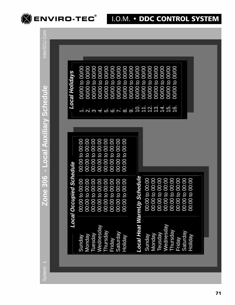
71
I.O.M. � DDC CONTROL SYSTEM
Inte
rSC
UC
om
Sun
day
00;0
0 to
00:
0000
:00
to 0
0:00
Mon
day
00:0
0 to
00:
0000
:00
to 0
0:00
Tues
day
00:0
0 to
00:
0000
:00
to 0
0:00
Wed
nesd
ay00
:00
to 0
0:00
00:0
0 to
00:
00T
hurs
day
00:0
0 to
00:
0000
:00
to 0
0:00
Frid
ay
00
:00
to 0
0:00
00:0
0 to
00:
00S
atur
day
00:0
0 to
00:
0000
:00
to 0
0:00
Hol
iday
00:0
0 to
00:
0000
:00
to 0
0:00
Sun
day
00:0
0 to
00:
00M
onda
y00
:00
to 0
0:00
Teus
day
00:0
0 to
00:
00W
edne
sday
00:0
0 to
00:
00T
hurs
day
00:0
0 to
00:
00Fr
iday
00:0
0 to
00:
00S
atur
day
00:0
0 to
00:
00H
olid
ay00
:00
to 0
0:00
Zone
306
- L
ocal
Aux
iliar
y S
ched
ule
Sys
tem
:1
Loca
lOcc
upie
dS
ched
ule
Loca
lHea
tWar
mU
pS
ched
ule
1.00
/00
to 0
0/00
2.00
/00
to 0
0/00
300
/00
to 0
0/00
4.00
/00
to 0
0/00
5.00
/00
to 0
0/00
6.00
/00
to 0
0/00
7.00
/00
to 0
0/00
8.00
/00
to 0
0/00
9.00
/00
to 0
0/00
10.
00/0
0 to
00/
0011
.00
/00
to 0
0/00
12.
00/0
0 to
00/
0013
.00
/00
to 0
0/00
14.
00/0
0 to
00/
0015
.00
/00
to 0
0/00
16.
00/0
0 to
00/
00
Loca
lHol
iday
s
72
DDC CONTROL SYSTEM � I.O.M.�Zone (Address) - Auxiliary Schedule� Screen(see previous page for screen example)
The Zone - Auxiliary Schedule screen will allow for the individual occupied/unoccupied scheduling of each VAV zoneterminal. This option is not currently available but will be in the near future. See the sample screen on the previouspage. There are 3 setup blocks within this screen to handle the following functions.
1. Local Occupied Schedule (Daily VAV zone terminal occupied times.)a. Left column displays day of week and holiday designation. The holiday designation applies to all
holiday periods assigned in the Local Holidays block to the right.b. Center column displays the first available daily local occupied mode. From and to occupied times
must be set in 24 hour clock format. If no occupied period is desired, use the �00:00 to 00:00�format entry.
c. Right column displays the second available daily local occupied mode. From and to occupiedtimes must be set in 24 hour clock format. If no occupied period is desired, use the �00:00 to00:00� format entry.
2. Local Heat Warm-up Schedule (Local heat application only.)a. Left column displays day of week and holiday designation. The holiday designation applies to all
holiday periods assigned in the Local Holidays block to the right.b. Right column displays the available daily and holiday warm-up times.
3. Local Holidays (Alternate holiday period scheduling.)a. Left column displays holiday number. 16 different holiday periods are available.b. Right column allows entry of specific holiday period in day/month format.
73
I.O.M. � DDC CONTROL SYSTEMAuxiliary Commands and �Help� Screens
(see pages 77 - 86 for screen examples)
Every screen in the VTMON program has an available �Help� screen. These screens are designed to give the start uptechnician or system operator a quick reference to the auxiliary commands available for use with the VTMON program.These auxiliary commands are broken down into two different categories, Standard commands and Diagnostic Modecommands.
The standard commands are available to the operator at any time during standard program operation, provided that theprogram is in the applicable screen. Diagnostic Mode commands are available only when the command line option �D�is used while initiating the VTMON program.
Each command includes either a �Function� key, the �Alt� key or the �Ctrl� key. In the case of the �Alt� or �Ctrl� keys,the proper key must be pressed simultaneously with the corresponding alpha or numeric key. For example, to perform asoftware reset on a controller, the <Alt> and <Z> keys must be pressed at the same time.
Although each help screen displays a brief overview of each command, the following are more detailed explanations ofeach.
1. Standard Commandsa. <F1>
This command will cause the appropriate �Help� menu screen to appear for whichever VTMONprogram screen is currently being viewed.
b. <Alt> <E>This command is used only in the �System Control Unit - Configuration Settings� screen. It willcause a pop up box to appear which will allow the entry or editing of an individual SCU password.See chapter 9 for complete password instructions.
c. <Alt> <S>This command is used only in the �System Control Unit - Configuration Settings� screen. It will cause apop up box to appear which will allow the entry or editing of a multiple SCU system password. See chapter9 for complete password instructions.
d. <Alt> <R>This command will cause a �Read� box to appear. This function will cause the computer to read the storedparameters from an SCU, BTC or VAV zone terminal controller. It will then store the data into a computerdisk file that is created when a file name is entered into the �Read� box.
e. <Alt> <W>This command will cause a �Write� box to appear. This function will cause the computer to read thestored parameters from the computer file name entered into the �Write� box. These parameters will thenbe downloaded into the controller currently being accessed, overwriting the existing parameters beingstored in that controller.
f. <Alt> <Z>This command will cause a software reset to be executed either in the controller currently beingaccessed or, from the �ETI DDC Network� screen, the controller address where the reverse videoblock is currently located.

74
DDC CONTROL SYSTEM � I.O.M.g. <Alt> <T>
This command will cause the update �Diamond� which scrolls down the left side of the �ETI DDCNetwork� screen and updates the controller address data to immediately return to the top of the screen.
h. <Alt> <C>This is a dual purpose command, depending on which screen is currently being accessed. In the �ETI DDCNetwork� screen, it will clear all displayed data and cause the update �Diamond� to return to the top of thescreen and begin a new screen update. In the �Zone - Monitor� screen, it will clear and reset both the�Unoccupied Override� timer and the accumulated �Total Override Time� counter.
i. <Alt> <U>This command will cause the controller to change to unoccupied mode when the zone is under SCUschedule control. The controller will return to occupied mode after one poll is initiated by the SCU.
j. <Alt> <O>This command will cause the controller to change to occupied mode when the zone is under SCUschedule control. The controller will return to unoccupied mode after one poll is initiated by theSCU. This command will function only if the controller is accessed by the VTMON program.
k. <Alt> <N>This command will cause the controller to leave any special mode that has been commanded and return tothe �Normal� operating mode. It will also cause the activation of a recently altered unit address that wasentered into the �User Settings� screen.
l. <Alt> <A>This command will cause all SCU�s, BTC�s and zone controllers to leave any special mode that hadbeen commanded and return to �Normal� operating mode. It will also cause the activation of anyrecently altered unit address that was entered into a �User Settings� screen on any controller.
m. <F6>This command will cause the suspension of the automatic polling process initiated by the SCU while thecomputer is running the VTMON program and is connected to the system. The SCU or SCU�s willreturn to automatic polling when the VTMON program communication to the system is terminated. If the�D� (debug) command line option is not being used, the polling countdown timer at the lower right handcorner of the screen will be removed.
n. <F7>The command will cause the automatic polling process initiated by the SCU to be re-established if it hasbeen suspended by the <F6> command.
o. <F9>This command will shift communication to the next lower system number in a multisystem network.
p. <F10>This command will shift communication to the next higher system number in a multisystem network.
q. <Alt> <P>This command will initiate an immediate, single SCU polling of the network. This command functionsonly when the VTMON program is in �Inter-SCU� communication mode. (The VTMON program willdefault to the �Inter-SCU� communication mode.) Functions even if the SCU�s automatic polling issuppressed.

75
I.O.M. � DDC CONTROL SYSTEMr. <Ctrl> <F>
This command will send a form feed command to any parallel printer attached to the computer running tothe VTMON program.
2. Diagnostic Mode Commands
a. <F8>This command will clear and reset the communication �Percentage of Error� counter found at thebottom of every screen when running the VTMON program in the debug mode.
b. <Alt> <O>This command will cause the SCU to leave the �Automatic� mode and enter the override modessequentially each time the <Alt> <O> keys are pressed. The system will go from �Automatic� to�Cooling Override� to �Heating Override� to �Fan Override� and back to �Automatic� mode. Thiscommand will function only while the SCU is being accessed by the VTMON program.
c. <Alt> <1>This command provides various functions depending on the unit being accessed by the VTMONprogram. The SCU will turn on output relay #1. The zone controller will open the damper fully and set themodulating output to the fully off voltage. The BTC will open damper actuator #1 only, turn off all otherdamper actuator outputs and set the modulating output to 2.5 VDC.
d. <Alt> <2>This command provides various functions depending on the unit being accessed by the VTMON program.The SCU will turn on output relay #2. The zone controller will close the damper fully and set themodulating output to the fully off voltage. The BTC will close damper actuator #1 only, turn off all otherdamper actuator outputs and set the modulating output to 3.4 VDC.
e. <Alt> <3>This command provides various functions depending on the unit being accessed by the VTMON program.The SCU will turn on output relay #3. The zone controller will turn on the fan output and set themodulating output to the fully off voltage. The BTC will open damper actuator #2 only, turn off all otherdamper actuator outputs and set the modulating output to 5 VDC.
f. <Alt> <4>This command provides various functions depending on the unit being accessed by the VTMON program.The SCU will turn on output relay #4. The zone controller will turn on staged heat output #1 and set themodulating output to 1/3 of it�s total voltage. The BTC will close damper actuator #2, turn off all otherdamper actuator outputs and set the modulating output to 6.7 VDC.
g. <Alt> <5>This command provides various functions depending on the unit being accessed by the VTMON program.The SCU will turn on output relay #5. The zone controller will turn on staged heat output #2 and set themodulating output to 2.3 of it�s total voltage. The BTC will open damper actuator #3, turn off all otherdamper actuator outputs and set the modulating output to 7.5 VDC.
h. <Alt> <6>This command provides various functions depending on the unit being accessed by the VTMON program.The SCU will turn on output relay #6. The zone controller will turn on staged heat output #3 and set themodulating output to it�s full on voltage. The BTC will close damper actuator #3, turn off all other damperactuator outputs and set the modulating output to 10 VDC.
76
DDC CONTROL SYSTEM � I.O.M.i. <Alt> <7>
This command provides various functions depending on the unit being accessed by the VTMON program.The SCU will turn on output relay #7. The zone controller will turn off all outputs. The BTC will turn offall outputs.
j. <Alt> <8>This command provides various functions depending on the unit being accessed by the VTMON program.The SCU will turn on output relay #8. The zone controller will set it�s modulating output to 10 VDC. TheBTC will open all 3 damper actuators simultaneously.
k. <Alt> <9>This command provides various functions depending on the unit being accessed by the VTMON program.The SCU will turn off all 8 output relays. The zone controller will set it�s modulating output to 0 VDC.The BTC will close all 3 damper actuators simultaneously.
l. <Alt> <L>This command provides various functions depending on the unit being accessed by the VTMON programand is used for calibration purposes only. The zone controller will drive the damper actuator to control atthe minimum cooling CFM. The BTC will allow the �Offset� calibration factor to be adjusted.
m. <Alt> <H>This command provides various functions depending on the unit being accessed by the VTMON programand is used for calibration purposes only. The zone controller will drive the damper actuator to control atthe maximum cooling CFM. The BTC will allow the �Slope� calibration factor to be adjusted.
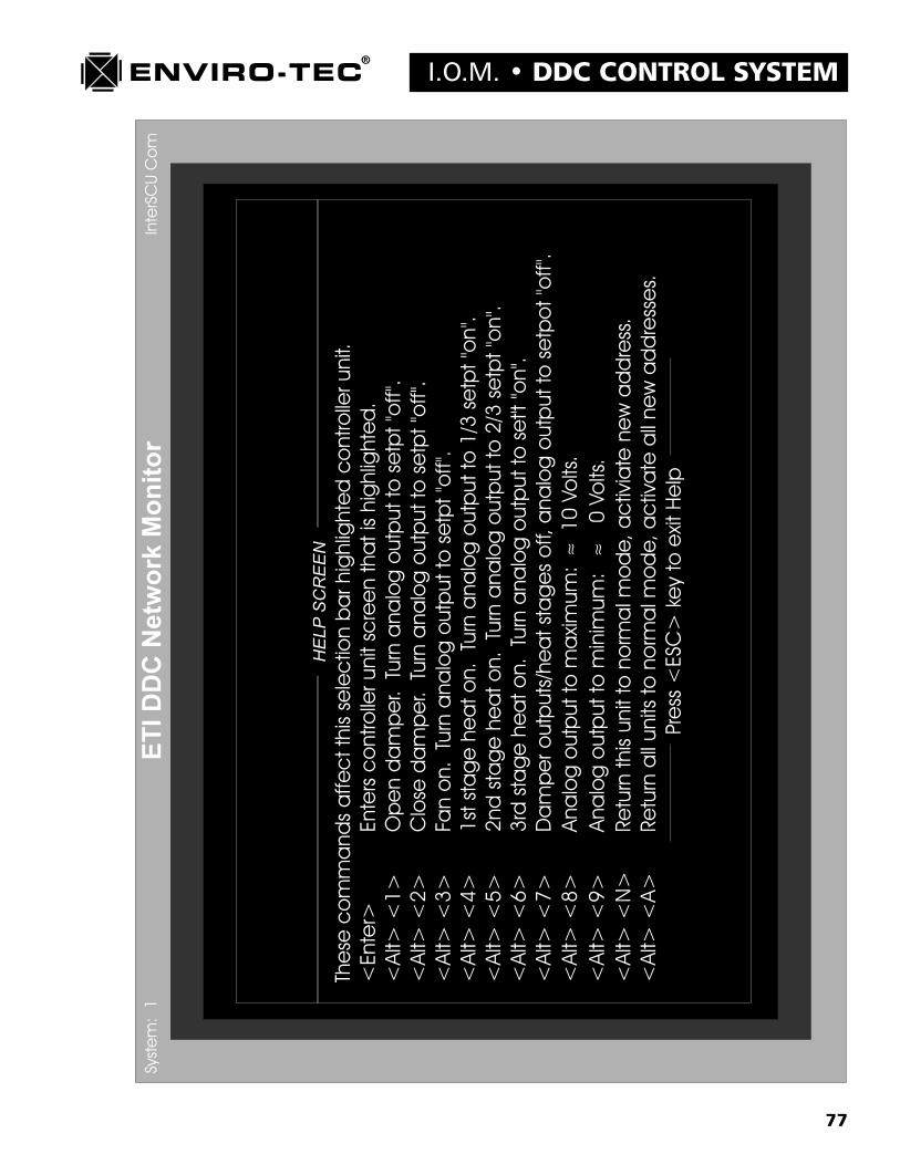
77
I.O.M. � DDC CONTROL SYSTEM

78
DDC CONTROL SYSTEM � I.O.M.

79
I.O.M. � DDC CONTROL SYSTEM
80
DDC CONTROL SYSTEM � I.O.M.

81
I.O.M. � DDC CONTROL SYSTEM
82
DDC CONTROL SYSTEM � I.O.M.
83
I.O.M. � DDC CONTROL SYSTEM
84
DDC CONTROL SYSTEM � I.O.M.
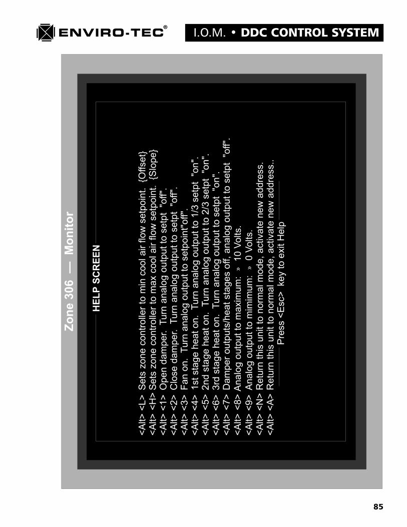
85
I.O.M. � DDC CONTROL SYSTEM

86
DDC CONTROL SYSTEM � I.O.M.

87
I.O.M. � DDC CONTROL SYSTEMDiagnostic Mode Test Variable Screens(see page 89 for screen example)
The SCU, BTC and zone controllers each have their own low level, test variable screens. These screens will be dis-played only when the �D� (Diagnostic) command line option is used while initiating the VTMON program. The testvariables or debug screen can be found by accessing a controller and paging down through all of the standard screens.The debug screen will be the very last screen found.
The information contained within the test variables screen is useful in various troubleshooting functions which may beperformed by an on site technician or by the factory via a modem connection. The following is a line by line explanationof each screen.
1. �System Control Unit - Test Variables� Screen (See sample screen)A. Operational Variables
1. Version: Designates the software version number that is programmed into the EPROM memorychip on board the controller.
2. Revision: Designates the revision of the software version number that is programmed into theEPROM memory chip on board the controller.
3. CPU Program Type: Designates the type of microprocessor that must be utilized with the abovesoftware version and revision.
4. Unit Addr High: High byte of controller unit address. Same as system number. (0-99)
5. Unit Addr Low: Low byte of controller unit address. Zone number on system. (1-64)
6. Command: Displays the last command sent to the SCU from the VTMON program. As soon as thatcommand is executed, the display returns to �No Command�.
7. Special Mode: Displays the controllers current operating mode as commanded by the VTMONprogram. If no special mode has been commanded, �Normal Mode� will be displayed.
8. Analog Output 1: Displays the �AO1� analog output register value between 0 and 255 bits. Thistranslates to 0 bits = 0 VDC and 255 bits = 10 VDC.
9. Analog Output 2: Displays the �AO2� analog output register value between 0 and 255 bits. Thistranslates to 0 bits = 0 VDC and 255 bits = 10 VDC.
10. AI0 - Outside Temp: Analog input that is being read on the controllers first A/D port. This port isassigned to the outside air temperature sensor. Possible values are between 0 and 16,368. If anasterisk (*) is displayed, the analog input channel is either �Open� or �Shorted�, possiblyindicating a failed sensor. This sensor is optional and not required for system operation.
11. AI1 - Key Lock: Analog input that is being read on the controllers second A/D port. This port isassigned to the operators panel keypad lockout function. Possible values are between 0 and16,368. If the ETKEY has been inserted into the �Stat� port on the ETDUA8 SCU motherboard to lock out the operators keypad, the display will be some value close to 0. If the ETKEY hasnot been used, the display will be some value close to 16,368.
88
DDC CONTROL SYSTEM � I.O.M.12. AI2 - Duct Temp: Analog input that is being read on the controllers third A/D port. This port is
assigned to the AHU discharge duct temperature sensor. Possible values are between 0 and 16,368. Ifan asterisk (*) is displayed, the analog input channel is either �Open� or �Shorted�, possiblyindicating a failed sensor. This sensor is NOT optional and IS required for system operation.
13. AI3 - Inlet Temp: Analog input that is being read on the controllers fourth A/D port. This port isassigned to the AHU inlet or return air temperature sensor. Possible values are between 0 and 16,368.If an asterisk (*) is displayed, the analog input channel is either �Open� or �Shorted,� possiblyindicating a failed sensor. This sensor is optional and not required for system operation.
B. Aux A/Ds at J7-#
This block is for factory use only.
C. Communications Flag Byte
This block is for factory use only.

89
I.O.M. � DDC CONTROL SYSTEMIn
terS
CU
Com
Rea
d:20
5E
rror
:0
%E
rror
:0.
0%49
Onl
ine
Sys
tem
Con
trol
Uni
t -
Test
Var
iabl
esS
yste
m:
1
Ope
ratio
nalV
aria
bles
Com
mun
icat
ions
Flag
Byt
eVe
rsio
n9
Rev
isio
n-
CP
U P
rogr
am T
ype
80C
196
Uni
t Add
r H
igh
1U
nit A
ddr
Low
44C
omm
and
No
Com
man
dS
peci
al M
ode
Nor
mal
Mod
eA
nalo
g O
utpu
t 114
7A
nalo
g O
utpu
t 225
5A
I0 -
Out
side
Tem
p*
9412
* S
enso
r O
pen/
Not
Con
nect
edA
I1 -
Key
Loc
k16
355
Ai2
- D
uct T
emp
*16
352
* AI3
- In
let T
emp
*16
354
*S
enso
r O
pen/
Not
Con
nect
ed
A/D
-1 L
6
A/D
-3
L
1
5A
/D-4
5471
A
/D-6
L
15
1.S
CU
PA
SS
DO
WN
BIT
SO
FF
2.S
CU
BU
S R
EC
EIV
ING
OF
F3.
TN
ET
TR
AN
SM
ITT
ING
OF
F4.
SB
UF
TX
LO
AD
ED
ON
5.PA
SS
DO
WN
BY
TE
OF
F6.
INIT
IAT
E P
OLL
ING
OF
F7.
SC
U B
US
AC
TIV
EO
N8.
SC
U B
US
RE
CV
GIP
OF
F
Aux
A/D
sat
J7-#
90
DDC CONTROL SYSTEM � I.O.M.2. �Static Pressure Controller - Test Variables� Screen (See sample screen, page 92)
A. Internal Operational Variables1. Version: Designates the software version number that is programmed into the EPROM memory
chip on board the controller.
2. Revision: Designates the revision of the software version number that is programmed into theEPROM memory chip on board the controller.
3. CPU Program Type: Designates the type of microprocessor that must be utilized with theabove software version and revision.
4. Unit Addr High: High byte of controller unit address. Same as system number. (0-99)
5. Unit Addr Low: Low byte of controller unit address. Zone number on system. (1-64)
6. Command: Displays the last command sent to the SCU from the VTMON program. As soon as thatcommand is executed, the display returns to �No Command�.
7. Special Mode: Displays the controllers current operating mode as commanded by the VTMONprogram. If no special mode has been commanded, �Normal Mode� will be displayed.
8. Stack Peak: Indicates where memory is being overwritten.
9. AI0 - Pressure: Analog input that is being read on the controllers first A/D port. This port isassigned to the static pressure sensor. Possible values are between 0 and 16,368. If an asterisk (*)is displayed, the analog input channel is either �Open� or �Shorted�, possibly indicating a failedsensor.
10. AI1 - Unused: Analog input that is being read on the controllers second A/D port. This port iscurrently not being used.
11. AI2 - Unused: Analog input that is being read on the controllers third A/D port. This port iscurrently not being used.
12. AI3 - Unused: Analog input that is being read on the controllers fourth A/D port. This port iscurrently not being used.
13. Press Bit Count: Displays the static pressure analog input register bit value. Possible values arebetween 0 and 1023 bits.
14. Static Pressure: Actual static pressure measurement displayed in inches of water gain.
15. Analog Output: Displays the �AO1� analog output register value between 0 and 255 bits. Thistranslates to 0 bits = 0 VDC and 255 bits = 10 VDC.
16. Digital Outputs: This number represents the decimal equivalent of the binary total of the activedamper actuator outputs. In normal mode, there would be 3 display possibilities, 0 for nooutputs on, 21 for outputs 1, 3 and 5 on and 42 for outputs 2, 4 and 6 on.
17. Ticks: Program timer ticks measured in 7 AC cycle segments.
91
I.O.M. � DDC CONTROL SYSTEM18. Damper Timer: Factory use only.
19. SCU Timer Check: Count down timer to disregard last SCU command to open damper.
20. Stat Key: 191 Filler: Values read from ETDIS display stat processor during setup or monitoring via useof ETDIS display stat. Factory use only.
21. Stat D0: Display character sent to first ETDIS display stat LED indicator.
22. Stat D1: Display character sent to second ETDIS display stat LED indicator.
23. Stat D2: Display character sent to third ETDIS display stat LED indicator.
24. Stat D3: Display character sent to fourth ETDIS display stat LED indicator.
25. Stat Display: Factory use only.
26. Smart Stat: Factory use only.
27. Response Time Count: Factory use only.
28. Pressure Pivot Pt: Static pressure curve point at which calibration pivot occurs.
29. Display Offset Adj: Factory calibration use only.
30. Stored Offset Adj: Factory calibration use only.
31. Display Slope Adj: Factory calibration use only.
32. Stored Slope Adj: Factory calibration use only.
33. Calib Slope Adj: Factory calibration use only.

92
DDC CONTROL SYSTEM � I.O.M.
93
I.O.M. � DDC CONTROL SYSTEM3. �Zone (Address) - Test Variables (See sample screen, page 95)
A. Internal Operational Variables1. Version: Designates the software version number that is programmed into the EPROM memory
chip on board the controller.
2. Revision: Designates the revision of the software version number that is programmed into theEPROM memory chip on board the controller.
3. CPU Program Type: Designates the type of microprocessor that must be utilized with theabove software version and revision.
4. Unit Addr High: High byte of controller unit address. Same as system number. (0-99)
5. Unit Addr Low: Low byte of controller unit address. Zone number on system. (1-64)
6. Command: Displays the last command sent to the SCU from the VTMON program. As soon asthat command is executed, the display returns to �No Command�.
7. Special Mode: Displays the controllers current operating mode as commanded by the VTMONprogram. If no special mode has been commanded, �Normal Mode� will be displayed.
8. Digital Outputs: This number represents the decimal equivalent of the binary total of the activedigital outputs.
9. Analog Output: Displays the analog output register value between 0 and 255 bits. This translatesto 0 bits = 0 VDC and 255 bits = 10 VDC.
10. AI0 - Airflow: Analog input that is being read on the controllers first A/D port. This port is assignedto the airflow sensor. Possible values are between 0 and 16,368. If an asterisk (*) is displayed, theanalog input channel is either �Open� or �Shorted�, possibly indicating a failed sensor.
11. AI1 - Space Temp: Analog input that is being read on the controllers second A/D port. This port isassigned to the space temperature sensor. Possible values are between 0 and 16,368. If an asterisk (*)is displayed, the analog input channel is either �Open� or �Shorted�, possibly indicating a failed sensor.
12. AI2 - Duct Temp: Analog input that is being read on the controllers third A/D port. This port isassigned to the duct temperature sensor. Possible values are between 0 and 16,368. If an asterisk(*) is displayed, the analog input channel is either �Open� or �Shorted�, possibly indicating a failedsensor.
13. AI3 - Stat Temp Spt: Analog input that is being read on the controllers fourth A/D port. This port isassigned to the ETTS regular thermostat temperature setpoint only. Possible values are between 0 and16,368. If an asterisk (*) is displayed, the analog input channel is either �Open� or �Shorted,� possiblyindicating a failed sensor.
14. Outside Air Temp: This temperature display is received from the SCU if the SCU is utilizing theoptional outside air temperature sensor.
15. Cal Min AirFl Pt: Minimum airflow point on which the airflow curve pivots during calibration.
94
DDC CONTROL SYSTEM � I.O.M.16. Temp Offset: Actual temperature offset above cooling setpoint or below heating setpoint displayed by
the �ETI DDC Network� screen for each VAV zone terminal unit address.
17. Temp Spt: Space temperature setpoint dialed in on the ETTS regular thermostat if used.
18. Prev Space Temp: Used to calculate rate of change in space temperature for PID calculation.
19. Float Pt Spt: Next scheduled output �On� timer value when �Floating Point� type hot water valve isused.
20. Float Pr Timer: Scheduled output �On� timer active countdown for �Floating Point� type hot watervalve.
21. CV Fan Timer: Series fan powered terminal fan motor delay �On� timer. Used to prevent backwardsfan motor rotation.
22. Damper Timer: Factory use only.
23. Sys Ticks Timer: Program timer ticks measured in 7 AC cycle segments.
24. Derivative: PID algorithm derivative counter.
25. Timer: PID algorithm derivative timer.
26. Integral: Clng 0.0 Htng 0.0: Summation of cooling or heating required for use in integral portion ofPID algorithm.
27. Stat Spt: Clng Htng: Thermostat setpoint values for cooling and heating.
28. Stat Disp: Control character for ETDIS thermostat display. Factory use only.
29. Smart Stat Count: Active timer showing count since ETDIS display thermostat was last read.
30. Stat Key: Filler: Values read from ETDIS display stat pick processor. Factory use only.
31. Stat D0: Display character sent to first ETDIS display stat LED indicator.
32. Stat D1: Display character sent to second ETDIS display stat LED indicator.
33. Stat D2: Display character sent to third ETDIS display stat LED indicator.
34. Stat D3: Display character sent to fourth ETDIS display stat LED indicator.
95
I.O.M. � DDC CONTROL SYSTEM

96
DDC CONTROL SYSTEM � I.O.M.
Chapter 6
ENVIRO-TEC DDC CONTROL SYSTEMCOMPONENT START UP GUIDELINES
A. VAV Zone Terminals
1. Check all power and communication wiring terminations to the zone terminal control enclosure.Ensure that all wiring and associated termination�s are in compliance with the guidelines presented inChapter 3 of this manual. The 3 position connector on RS485 communication terminal J1 should beleft unplugged at this time.
2. Measure the incoming line voltage supplying the control transformer. Insure that it matches theprimary voltage rating listed on the transformer. Remove any tools and equipment from the controlenclosure. Move control transformer disconnect switch to the �On� position. If a distributed 24VAC power source is to be used, repeat item 1 at all terminals before activating the 24 VAC powersource.
3. The red �DG� or Diagnostic LED will begin flashing at a rate of approximately one cycle persecond. Also, depending on the current communication mode, the red �RX� or Receive and �TX� orTransmit LED�s may flash intermittently.
4. The �Network� address may now be set into the DDC VAV controller. Either the �Setaddr� setaddress program, used in conjunction with a computer or the �ETDIS� display thermostat method canbe utilized. Instructions for both methods of setting a unit address are found in Chapter 5 of this book.These methods are equally acceptable. The 3 position connector on RS485 communication terminal J1should be plugged in at this time.
5. The above 4 steps need to be repeated at all Single Duct and Fan Powered VAV terminals.
B. Bypass Terminals and Static Pressure Controllers
1. Check all power and control wiring termination�s to the bypass terminal control enclosure(s) and thestatic pressure controller. Insure that all wiring and associated termination�s are in compliance with theguidelines presented in Chapter 3 of this manual. The 3 position connector on RS485 communicationterminal J1 of the static pressure controller (BTC) should be left unplugged at this time.
2. Measure the incoming line voltage supplying the control transformer located in the BPV-01 controlenclosure. Insure that it matches the primary voltage rating listed on the transformer. Remove anytools and equipment from the control enclosure. Move control transformer disconnect switch to the�On� position. If a distributed 24 VAC power source is to be used, repeat item 1 at all terminals beforeactivating the 24 VAC power source.
3. Once the 24 VAC supply is activated, check the duct mounted BTC-01 controller. The red �DG� orDiagnostic LED will begin flashing at a rate of approximately one cycle per second. Also,depending on the current communication mode, the red �RX� or Receive and �TX� or TransmitLED�s may flash intermittently.
97
I.O.M. � DDC CONTROL SYSTEM4. The �Network� address may now be set into the DDC static pressure controller. Either the �Setaddr�
set address program, used in conjunction with a computer or the �ETDIS� display thermostatmethod can be utilized. Instructions for both methods of setting a unit address are found in Chap-ter 5 of this book. These methods are equally acceptable. The 3 position connector on RS485communication terminal J1 should be plugged in at this time.
5. The above 4 steps need to be repeated at all Static Pressure controllers and Bypass terminals.
C. System Control Units
1. Check all power and control wiring termination�s to the System Control Unit enclosure. Insure that allwiring and associated terminations are in compliance with the guidelines presented in Chapter 3 of thismanual. The 3 position connectors on RS485 communication terminals J1(VAV Zone buss) and J2(Inter SCU buss) should be left unplugged at this time.
2. On the ETDUX8 and ETDUX4A2 output boards, just below the dry contact modules, there are 2 slideswitches. One is a cooling override switch and one is a heating override switch. Both of these switchesneed to be in the �OFF� position (to the right) during start-up. These switches are ONLY for emergencyoperation should a total SCU failure occur. They are designed to bypass the dry contacts for manualoperation of either the first stage of heating or cooling in conjunction with the fan. These differ from the�COOL� and �HEAT� override buttons on the front of the SCU operators panel which are controlled bydischarge temperatures programmed into the memory.
3. Measure the incoming line voltage supplying the control transformer located in the SCU enclo-sure. Ensure that it matches the primary voltage rating listed on the transformer. Remove anytools and equipment from the control enclosure. Move control transformer disconnect switch to the�On� position. It is not recommended that the SCU be powered by a distributed 24 VAC controlvoltage loop. The isolation transformer supplied with the SCU should be used.
4. The red �DG� or Diagnostic LED on the ETDUA8 control board will begin flashing at a rate ofapproximately one cycle per second. Also, depending on the current communication mode, thered �RX� or Receive and �TX� or Transmit LED�s on both the Zone bus and SCU bus may flashintermittently.
5. Check the operators panel on the front of the SCU. Insure that the liquid crystal display reads �CurrentMode STANDBY� immediately upon power up. If the display reads any of the override functions suchas Heating, Cooling or Fan, press the �AUTO� button on the operators panel keypad to switch the SCUback to normal control mode.
6. The �Network� address may now be set into the System Control Unit. The �Setaddr� set addressprogram, used in conjunction with a computer must be utilized. Instructions for setting a SCU unitaddress are found in Chapter 5 of this book. The 3 position connector on RS485 communication termi-nal J1 should be plugged in at this time. If the system has multiple SCU�s, the 3 position connector onRS485 communication terminal J2 should be left disconnected until these steps have been completed onthe remaining systems.
D. Software Configuration
1. Enviro-Tec DDC controls are downloaded at the factory with default values that will allow the indi-vidual controller to function in an acceptable fashion in a stand alone mode. Network addressesmust be set before the controllers may function together and communicate as a system. These

98
DDC CONTROL SYSTEM � I.O.M.default values will most likely NOT match the engineered specifications for a particular job. Thedefault settings in each SCU, BTC and Zone controller must be checked and modified if necessary tocomply with engineered job specifications. Also, insure that VAV terminal sizes are compat-ible with design specification minimum and maximum CFM�s. Compare specified design CFM�sfor all VAV terminals with hose listed in Table D.1.
2. Insure that the correct �Box Type� and �Box Size� are entered in the Zone controller �Low LevelConfiguration Settings� screen, �Box Configuration� block. If local VAV terminal heat is to beused, the �Output Control� block has to be configured to operate within engineered specifications.
3. If a parallel fan powered terminal is used, the number of degrees Fahrenheit below heating setpointfor the fan to be turned on must be set in the �Low Level Configuration� screen �OutputConfiguration� block.
4. If a series fan powered box is used, the following sequence of events will occur which will prevent thefan from being energized if the wheel is spinning backwards. This sequence of events will occur aftereither a power up, soft reset or a switch from unoccupied to occupied mode.
a. The damper will begin to close.b. A 4 minute delay timer on the fan output will begin countdown.c. The damper takes a maximum of 2 minutes to come to a complete close.d. There will be at least a 2 minute period where the fan wheel will not be exposed to primary air.
During this time, the fan wheel will stop spinning.e. When the 4 minute timer has counted down, the fan output on the controller will then be
activated.
5. If a �SCU� or System Control Unit is to be used, insure that the Time of Day, occupied schedule and�On/Off� heating and cooling stage discharge temperatures are set properly. The Time of Day shouldbe factory set as well as heating and cooling stage discharge temperature defaults. These defaultsmay not be appropriate for the particular rooftop or package unit being controlled by the Enviro-Tec DDC system. Check the unit manufacturers operating specifications.
6. All setup capabilities on all Enviro-Tec DDC control components must be checked during the start-upprocedure. Due to the flexibility of these controls, it is impossible to anticipate the field requirementswhich must be met on any particular installation. It is the responsibility of the start-up technician toinsure that all setpoint values downloaded into these controllers are accurate and applicable toeach particular installation.
VAV Terminal(Values in CFM)
4 35 2255 55 3506 65 5508 120 1000
10 195 160012 280 230014 400 310016 550 4100
SIZE MINIMUM MAXIMUM
Table D.1

99
I.O.M. � DDC CONTROL SYSTEM
Chapter 7
ENVIRO-TEC DDC CONTROL SYSTEMSCU OPERATORS PANEL & ETDIS OPERATION
A. ETOP Operators Panel OperationThe ETOP operators panel is located on the front door of the SCU enclosure. The ETOP is equipped with a 2row, 16 character, liquid crystal display and a 20 button keypad. There is also a Quick Wire connection commu-nication port on the ETOP. All functions that can be monitored and/or altered via the VTMON program mayalso be monitored and/or altered, 1 line at a time, on the ETOP.
If there is a requirement to limit access to the ETOP for security reasons, the keypad may be locked out. Insertthe ETKEY into the �Stat� port on the ETDUA8 SCU motherboard. This will effectively disable the ETOPkeypad. The program line block that was being displayed when the ETKEY was inserted will continue to updatenormally, even though the keypad itself has been locked out.
AUTO FAN HEAT
JKL MNO PQR
VWX YZ
COOL
MENU
NEXT
ABC DEF GHIPREV
. ENTER+/
STU
7 8 9
4 5 6
1 2 3
0
ENVIRO-TEC®
100
DDC CONTROL SYSTEM � I.O.M.1. The following is a description of the ETOP function keys:
a. AUTO: This key will return the system to automatic control from any of the override functions.
b. FAN: This key will put the system into fan override. This override function will ignore the normalscheduling operation.
c. HEAT: This key will put the system into heat mode override. This override function will ignore thenormal scheduling operation as well as automatic mode selection based on demand. Heat override willcontrol discharge temperature based on programmed parameters.
d. COOL: This key will put the system into cool mode override. This override function will ignore thenormal scheduling operation as well as automatic mode selection based on demand. Cool override willcontrol discharge temperature based on programmed parameters.
e. MENU: This key will prompt the operator to enter the unit address desired for access.
f. NEXT: This key allows the operator to scroll forward through the program lines 1 at a time.
g. PREV: This key allows the operator to scroll backwards through the program line 1 at a time.
h. ENTER: This key allows the operator to scroll forward through the program 1 page at a time. Thepages are denoted by bold type and a �Diamond� symbol in the following program line listing blocks.
2. Selecting a Controller to Accessa. Press the MENU button. The display will change to:
ENTER ADDRESS:
b. Enter the system address of the desired controller (SCU - 0, BTC - 65, zone - 1-64):
ENTER ADDRESS:12
c. Press the ENTER button. The display will change to:
ZONE CONTROLLER12
d. The operator may now scroll through the program line blocks as required by using the NEXT, PREVand ENTER buttons.
e. To alter the data in any program line block, use the numeric portion of the keypad to enter therequired information. To clear or set to 0 the information in any program line block, press the decimal(�.�) button. For fixed, selection type entries, such as YES/NO, press the zero (0) button to toggle thechoices. Once the data in a program line block has been altered as required, press the NEXT, PREV,MENU or ENTER button to store the new data and move on.
101
I.O.M. � DDC CONTROL SYSTEM
System Control Unit Operator�s Panel Displays

102
DDC CONTROL SYSTEM � I.O.M.
103
I.O.M. � DDC CONTROL SYSTEM

104
DDC CONTROL SYSTEM � I.O.M.
System Controller Operator�s Panel Displays
105
I.O.M. � DDC CONTROL SYSTEM
Bypass Controller Operator�s Panel Displays
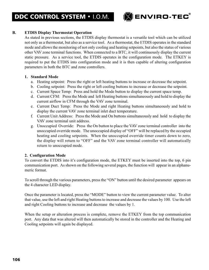
106
DDC CONTROL SYSTEM � I.O.M.
B. ETDIS Display Thermostat OperationAs stated in previous sections, the ETDIS display thermostat is a versatile tool which can be utilizednot only as a thermostat, but also as a service tool. As a thermostat, the ETDIS operates in the standardmode and allows the monitoring of not only cooling and heating setpoints, but also the status of variousother VAV zone terminal functions. When connected to a BTC, it will continuously display the currentstatic pressure. As a service tool, the ETDIS operates in the configuration mode. The ETKEY isrequired to put the ETDIS into configuration mode and it is then capable of altering configurationparameters in both the BTC and zone controllers.
1. Standard Modea. Heating setpoint: Press the right or left heating buttons to increase or decrease the setpoint.b. Cooling setpoint: Press the right or left cooling buttons to increase or decrease the setpoint.c. Current Space Temp: Press and hold the Mode button to display the current space temp.d. Current CFM: Press the Mode and left Heating buttons simultaneously and hold to display the
current airflow in CFM through the VAV zone terminal.e. Current Duct Temp: Press the Mode and right Heating buttons simultaneously and hold to
display the current VAV zone terminal inlet duct temperature.f. Current Unit Address: Press the Mode and On buttons simultaneously and hold to display the
VAV zone terminal unit address.g. Unoccupied Override: Press the On button to place the VAV zone terminal controller into the
unoccupied override mode. The unoccupied display of �OFF� will be replaced by the occupiedheating and cooling setpoints. When the unoccupied override timer counts down to zero,the display will return to �OFF� and the VAV zone terminal controller will automaticallyreturn to unoccupied mode.
2. Configuration ModeTo convert the ETDIS into it�s configuration mode, the ETKEY must be inserted into the top, 6 pincommunication port. As shown on the following several pages, the function will appear in an alphanu-meric format.
To scroll through the various parameters, press the �ON� button until the desired parameter appears onthe 4 character LED display.
Once the parameter is located, press the �MODE� button to view the current parameter value. To alterthat value, use the left and right Heating buttons to increase and decrease the values by 100. Use the leftand right Cooling buttons to increase and decrease the values by 1.
When the setup or alteration process is complete, remove the ETKEY from the top communicationport. Any data that was altered will then automatically be stored in the controller and the Heating andCooling setpoints will again be displayed.

107
I.O.M. � DDC CONTROL SYSTEM
Display Stat Zone Configuration Mode Displays for Zone Controller

108
DDC CONTROL SYSTEM � I.O.M.
[1] 0 = Normal Operation,1 = Open Damper and turn proportional output to setpoint off,2 = Close Damper and turn proportional output to setpoint off,3 = Turn Fan On and turn proportional output to setpoint off,4 = Turn 1st Stage Heat On/Tri-State valve open and proportional output goes to 1/3 setpoint on,5 = Turn 2nd Stage Heat On/Tri-State valve close and proportional output goes to 2/3 setpoint on,6 = Turn 3rd Stage Heat On and proportional output goes to full setpoint on,7 = All Stage Heating and Tri-State output off and turn proportional output to setpoint off,8 = Proportional output at maximum voltage » 10 Volts,9 = Proportional output at minimum voltage » 0 Volts,32 = Software Reset,34 = High Balancing Mode(using VTMon), 35=Low Balancing Mode(using VTMon).
[2] 0 = No Alarm Condition, 1 = Indication of Error when writing to EEPROM Memory.
[3] 0 = Use SCU Schedule, 1 = Use Smart Stat On/Off Timer, 2=Use Smart Stat On/Off Switch.
[4] 0 = SDV942 Standard, 1 = SDV945 No Local Reheat,2 = SDV945 with Staged (and Proportional) Local Heat control,3 = SDV945 with Tri-State (and Proportional) Local Heat control,4 = FVV945 No Local Reheat (Variable Volume Fan control only),5 = FVV945 with Staged (and Proportional) Local Heat control,6 = FVV945 with Tri-State (and Proportional) Local Heat control,7 = FCV945 No Local Reheat (Constant Volume Fan control only),8 = FCV945 with Staged (and Proportional) Local Heat control,9 = FCV945 with Tri-State (and Proportional) Local Heat control,10 = SDV945 Proportional Local Heat control,11 = FVV945 Proportional Local Heat control,12 = FCV945 Proportional Local Heat control.
[5] 0 = Normal Operation, 1 = Command to Clear Zone�s stored Password.
* If both Heating Dec & Cooling Inc are pressed in current setting mode, 0 or minimum is set.
109
I.O.M. � DDC CONTROL SYSTEM
[1] 0 = Normal Operation,1 = Open Damper 1 and turn V F Drive output on 1/4,2 = Close Damper 1 and turn V F Drive output on 1/3,3 = Open Damper 2 and turn V F Drive output on 1/2,4 = Close Damper 2 and turn V F Drive output on 2/3,5 = Open Damper 3 and turn V F Drive output on 3/4,6 = Close Damper 3 and turn V F Drive output completely on,7 = All Damper controlling outputs turned off and turn V F Drive output completely off ,8 = Open all Dampers and turn V F Drive output off,9 = Close all Dampers and turn V F Drive output off,30 = Simulates SCU opening dampers,32 = Software Reset,37 = Set Low pressure calibration,36 = Set High pressure calibration.
[2] 2 = 2 minutes, 3 = 1½ minutes, 4 = 1 minute, 5 = 50 seconds,6 = 40 seconds, 8 = 30 seconds, 10 = 25 seconds, 13 = 20 seconds.
[3] 0 = No Alarm Condition, 1 = Indication of Error when writing to EEPROM Memory.
[4] 0 = Normal Operation, 1 = Command to Clear Zone�s stored Password.
* If both Heating Dec & Cooling Inc are pressed in current setting mode, 0 or minimum is set.
Display Stat Configuration Mode Displays for BTC Controller
110
DDC CONTROL SYSTEM � I.O.M.
Chapter 8
ENVIRO-TEC DDC CONTROL SYSTEMSTATIC PRESSURE, AIRFLOW and TEMPERATURE
CALIBRATION PROCEDURES
As stated previously, all of the analog input data utilized by the Enviro-Tec DDC control system can be calibrated bysoftware, if required. This data consists of static pressure, airflow and various temperature readings. The followingprocedures are a guide to the calibration of these readings.
A. Temperature ReadingsTemperature readings consist of: Space Temp, Inlet Temp, Outside Temp and Discharge Temp. These readingsmay be adjusted by calibration should they be inaccurate in any way. There is also a calibration for the tempera-turesetpoint on the ETTS regular thermostat. Occasionally, the displayed temperature setpoint and the indicatedtemperature setpoint on the ETTS will not coincide. To calibrate any of these readings, simply enter the numberof degrees and/or tenths of degrees F required to adjust the display. If this entry is a negative number, press theminus (-) key AFTER the numeric entry is made, not before.
B. Airflow ReadingsWhen calibrating the airflow reading of a VAV zone terminal, the entire airflow curve of the terminal is beingadjusted. The low or minimum end of the curve is adjusted using the �Offset� calibration. This is the equivalentof an electronic �Zero� calibration. The high or maximum end of the curve is adjusted using the �Slope�calibration. This is the equivalent of an electronic �Gain� calibration.
In the event that an airflow calibration is required, the following procedure may be used to correct any inaccu-racies in the displayed CFM.
Step 1:Using a PC, run the VTMON program using command line option D. (see the chapter 5 section on using com-mand line options.) Enter into the screen of the VAV zone terminal that is to be calibrated. Type the <Alt><L>command. This will cause the controller to ignore the current CFM setpoint and force the minimum coolingCFM to become the artificial current setpoint.
Step 2:Watching the Zone - Monitor screen, wait till the actual CFM reading settles down to within the deadband of theminimum cooling CFM setpoint. With a calibrated flow hood, measure the actual CFM flowing through thezone diffusers.
Step 3:If the actual and displayed readings are outside the design specification, enter the difference between the two inthe �Airflow Offset� calibration location in the Zone - Low Level Configuration Settings screen. If a negativenumber is required, press the minus (-) key after the entry to subtract from the actual reading. Do not press theminus (-) before making the numeric entry.
Step 4:Check the Zone - Low Level Configuration screen and insure that the �Slope� is set to �0%�. Type the <Alt><H>command. This will cause the controller to ignore the current CFM setpoint and force the maximum coolingCFM to become the artificial current setpoint.

111
I.O.M. � DDC CONTROL SYSTEMStep 5:Watching the Zone - Monitor screen, wait till the actual CFM reading settles down to within the deadband of themaximum cooling CFM setpoint. With a calibrated flow hood, measure the actual CFM flowing through thezone diffusers.
Step 6:If the actual and displayed readings are outside the design specification, calculate the required slope percentageusing the following formula:
(Measured Airflow - Displayed Airflow Reading)Slope % = 10% X ���������������������������
(Displayed Airflow Reading - Calibration Offset)
Step 7:Enter the calculated slope % in the �Airflow Slope� calibration location in the Zone - Low Level ConfigurationSettings screen. If a negative number is required, press the minus (-) key after the entry to subtract from theactual reading. Do not press the minus (-) before making the numeric entry.
Step 8:Enter the <Alt><N> command which will instruct the controller to return to the normal control mode.
C. BTC Initial SetupBecause strict accuracy (within .02 wg) is usually not necessary for proper and safe static pressure control, andbecause controller calibration is accomplished at the factory, this reduced set of start-up instructions can befollowed which will result in excellent static pressure control.
Step 1:If using a PC, run the VTMON program using command line option D. (see the chapter 5 section on usingcommand line options.) If using the ETDIS display stat, follow the chapter 7 section using Display-Stat Con-figuration Mode Displays for BTC Controller.
Step 2:Set Bypass Pressure Setpoint and VFD Pressure Setpoint to .2 wg. Set both VFD Pressure Deadband andBypass Pressure Deadband to .05 wg.
Step 3:If using the VTMON program, enter into the Static Pressure monitor screen and type <Alt><L> (for low pres-sure calibration). This can be confirmed by paging down to the next screen called STATIC PRESSURE CON-TROLLER - TEST VARIABLES and checking the special mode indicator. If using the ETDIS display stat, setthe remote control to 37 (which stands for low pressure calibration).
Step 4:Set Pressure Offset Adjust to 0.
Step 5:Next, using the VTMON program, return to the Static Pressure monitor screen and type <Alt><H> (for highpressure calibration). To confirm again, press <PgDn> to STATIC PRESSURE CONTROLLER - TEST VARI-ABLES and check Special Mode indicator. If using the ETDIS display stat, set the remote control to 36 (whichstands for high pressure calibration).
112
DDC CONTROL SYSTEM � I.O.M.Step 6:Set Pressure Slope Adjust to 0.
Step 7:Type <Alt><A> to set all controllers back to normal and then enter in static pressures that are desired for systemoperation. If using an ETDIS display stat, set remote control to 0, which stands for normal operation. Also, setsystem static pressure setpoints following the guidelines in chapter 7 using Display-Stat Configuration ModeDisplays for BTC Controller.
D. BTC Static Pressure Calibration
In the event that a static pressure calibration is required, the following procedure may be used to correct anyinaccuracies in the displayed actual static pressure.
Step 1:Install the BTC and connect to either the Bypass Valves (BPV), the Variable Frequency Drive (VFD), or both, inaccordance with the submittal drawings found in chapter 4. Connect a Manometer, Magnahelic or other pres-sure sensing device on a separate probe located in the same vicinity as the BTC. Energize system in accordancewith the procedures outlined in chapter 6.
Step 2:If using a PC, then run the VTMON program using command line option D. (see the chapter 5 section on usingcommand line options.) If using the ETDIS display thermostat, follow the guidelines in chapter 7 using Display-Stat Configuration Mode Displays for BTC Controller.
Step 3:a. If using either bypass damper control or VFD only: Set Bypass Pressure Setpoint and VFD Pressure Setpointto some minimum value, i.e. from .1 to .3 wg. Set both VFD Pressure Deadband and Bypass Pressure Deadbandto .05 wg.b. If using both the bypass damper control and the VFD: Set VFD Pressure Setpoint to some minimum value,i.e. from .1 to .3 wg. Set Bypass Pressure Setpoint at least .3 wg above the chosen VFD Pressure Setpoint. Setboth VFD Pressure Deadband and Bypass Pressure Deadband to .05 wg.
Step 4:If using the VTMON program, access the Static Pressure monitor screen and type <Alt><L> (for low pressurecalibration). This can be confirmed by paging down to the next screen called STATIC PRESSURE CONTROL-LER - TEST VARIABLES and checking the Special Mode indicator. If using the ETDIS display stat, set remotecontrol to 37 (which stands for low pressure calibration).
Step 5:After setting a pressure setpoint the static pressure controller reading should fall or rise to the new pressuresetpoint value +/- the dead band setting. If the pressure doesn�t quite reach the static pressure setpoint then itmay be necessary to calibrate to a slightly higher pressure or to reduce the actual pressure by commanding VAVbox dampers to open. This latter case is accomplished by pressing <Alt><1> keys when each zone is high-lighted in the Network Monitor screen.
113
I.O.M. � DDC CONTROL SYSTEMStep 6:Once the pressure reading settles to around the static pressure setpoint, +/- the dead band, a comparison shouldbe made between the static pressure being read by the controller and pressure being measured by the calibratedpressure sensing device. To correct for any error between the two, enter into the Pressure Offset Adjustment thepressure difference that needs to be added to or subtracted from the controllers reading so that it will equal thecalibrated pressure sensing device reading.
Pressure Offset Adjust = actual measured pressure - uncorrected Controller Static Pressure
Step 7:Next, using the VTMON program, return to the Static Pressure monitor screen and type <Alt><H> (for highpressure calibration). To confirm again, press <PgDn> to STATIC PRESSURE CONTROLLER - TEST VARI-ABLES and check Special Mode indicator. If using the ETDIS display stat, set remote control to 36 (whichstands for high pressure calibration).
Step 8:Set Bypass Pressure Setpoint and VFD Pressure Setpoint to some maximum calibration value. This maximumvalue will be the highest pressure that is ever required as an accurate reading. Remember, the duct work willactually need to get up to this pressure (and somewhat beyond) to calibrate the system at the maximum calibra-tion pressure chosen. Therefore consideration needs to be given as to what pressures the duct work can with-stand and what maximum pressures are possible to obtain. Suggested maximum pressure is in the range from1.2 to 2 wg. The VFD Pressure Deadband and Bypass Pressure Deadband should be set from .05 wg to .20 wg.
Step 9:When the pressure reading settles once again around the static pressure setpoint, +/- the dead band setting,another comparison should be made between the static pressure being read by the controller and the pressurebeing measured by the calibrated pressure sensing device. (If the pressure doesn�t settle down and the systemuses a VFD, increase VFD full scale response time.) This time, correct the pressure reading value by enteringthe pressure difference into the pressure slope adjustment. Reduce or increase Pressure Slope Adjustment untilstatic pressure is within acceptable tolerances of measured pressure.
Pressure Slope Adjust = actual measured pressure - uncorrected displayed Controller Static Pressure
Step 10:Type <Alt><A> to set all controllers back to normal and then enter in static pressures that are desired for systemoperation. If using an ETDIS display stat, set remote control to 0, which stands for normal operation. Also, setsystem static pressure setpoints following the guidelines in chapter 7 using Display-Stat Configuration ModeDisplays for BTC Controller.
114
DDC CONTROL SYSTEM � I.O.M.
Chapter 9
ENVIRO-TEC DDC CONTROL SYSTEMSYSTEM PASSWORD OPERATION
The VTMON program has been given password protection capability. This is designed to protect the system againstnon-authorized parameter modifications. The password resides in the non-volatile memory on board the SCU. EachSCU may have it�s own password on a multi SCU system, or they may all use the same password.
There is no password loaded into the SCU memory when shipped from the factory. This means that there is unlimitedaccess to the system until such time as a password is loaded into the SCU memory. It is important to remember that theVTMON program will also allow the system to be monitored by an operator without the password, but no parametersmay be altered.
A. To install a password using the VTMON program, use the following steps.
1. Access the system with the VTMON program normally.
2. Once into the �ETI DDC Network� screen, access the SCU.
3. Once into the �System Control Unit - Monitor� screen, press the �Page Down� key 3 times. This willdisplay the �System Control Unit - Configuration Settings� screen.
4. To begin the password entry mode for the SCU currently being accessed only, press the <Alt><E>keys simultaneously. The �Editing Password� block will be displayed in the middle of the screen. See thesample screen on the following page.
5. To begin the password entry mode for all of the SCU�s networked together on the system, press the<Alt><S> keys simultaneously. The �Editing Password� block will be displayed in the middle of thescreen. See the sample screen on the following page.
6. Enter the desired password. The password may consist of up to 16 alphanumeric or keyboard characters.When completed, press the �Enter� key to leave the password entry mode. This will set the newpassword into the SCU�s memory. Press the �ESC� key to exit without changing the password.
7. To confirm the password that was entered is correct, press either <Alt><E> or <Alt><S>. Edit ifincorrect and press the �Enter� key or, if correct, press either the �Esc� key or the �Enter� key. This stepmay be repeated as many times as necessary.
8. To deactivate a password, repeat steps 1 thru 5. Press the �Delete� key, then the �Enter� key. This willcause all blanks to be displayed in the �Editing Password� block. The password will now bedeactivated. Press the �Enter� key to leave the password entry mode.
9. To alter the password, use the same steps that are utilized to enter a new password.
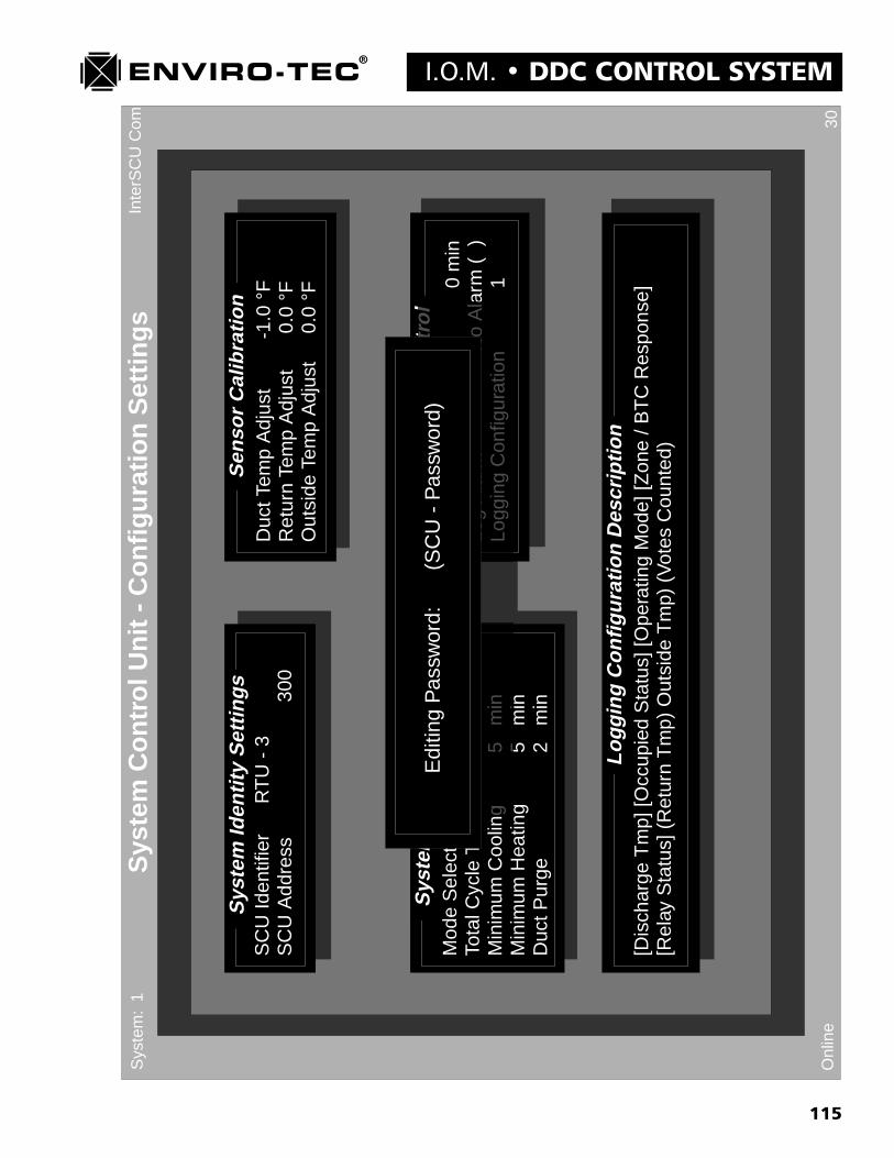
115
I.O.M. � DDC CONTROL SYSTEM
Inte
rSC
UC
om 30O
nlin
e
Sys
tem
Co
ntr
ol U
nit
- C
on
fig
ura
tio
n S
etti
ng
sS
yste
m:
1
Sys
tem
Iden
tity
Set
tin
gs
Sen
sor
Cal
ibra
tio
n
Sys
tem
Co
nfi
gu
rati
on
Lo
ggin
gC
on
tro
l
SC
U Id
entif
ier
RT
U -
3S
CU
Add
ress
300
Mod
e S
elec
ted
By
Maj
ority
Vot
eTo
tal C
ycle
Tim
e30
min
Min
imum
Coo
ling
5 m
inM
inim
um H
eatin
g5
min
Duc
t Pur
ge2
min
Duc
t Tem
p A
djus
t-1
.0 °
FR
etur
n Te
mp
Adj
ust
0.0
°FO
utsi
de T
emp
Adj
ust
0.0
°F
Logg
ing
Inte
rval
0 m
inLo
g A
larm
No
Ala
rm (
)Lo
ggin
g C
onfig
urat
ion
1
[Dis
char
ge T
mp]
[Occ
upie
d S
tatu
s] [O
pera
ting
Mod
e] [Z
one
/ BT
C R
espo
nse]
[Rel
ay S
tatu
s] (
Ret
urn
Tm
p) O
utsi
de T
mp)
(V
otes
Cou
nted
)
Lo
ggin
gC
on
fig
ura
tio
nD
escr
ipti
on
Co
nfi
gu
rati
on
By
Maj
ority
Vot
ee
30 m
ing
5 m
inng
5m
in
Lo
ggin
gC
on
tro
lLo
ggin
g In
terv
alLo
g A
larm
No
Al a
Logg
ing
Con
figur
atio
n
Edi
ting
Pas
swor
d:(S
CU
- P
assw
ord)

116
DDC CONTROL SYSTEM � I.O.M.B. To Access a Password Protected System using the VTMON program.
1. Run the VTMON program. The standard copyright statement is displayed. After pressing any key,the �ETI DDC Network� screen will be displayed with the password request box in the center.
2. The password request box states �Enter Password�. The operator must enter the password at this time.The operators entry will be displayed in X�s.
3. If the correct password has been entered, the VTMON program will allow unrestricted access to thesystem.
4. If an incorrect password has been entered, the following choices will be displayed:
a. Retry in case mistake was made entering passwordb. Password incorrect, enter in Monitor Mode onlyc. Exit program altogether
5. A maximum of 5 minutes are allowed for retrying password entries. This is to prevent tying up thesystem. If the operator has not entered the correct password within 5 minutes, the program willautomatically exit itself.
C. Password Operation Using the ETOP Operators Panel1. Confirm that a stat key is not being used to lock the operators keypad. This is done by installing a stat key
into the quick connector jack labeled STAT on the SCU board in the Operators Panel. If the keypadresponds at all, then is has not been locked.
2. Press the �Enter� key continuously until the program line block �EDITING PASSWORD� (the lastline block in the SCU program) is displayed on the first line of liquid crystal display. The second linewill display the password when one has been entered.
3. To enter a password:
a. To enter a number, press the key with that number on it, then press the �0� key.
b. To enter a lower case letter, press the key with the desired letter on it, then press either the 1, 2 or 3 keydepending on which position the desired letter occupies on the key. For instance, to enter a lower case�s�, press the �STU� key and then the number �1� key, indicating that �s� is the first letter on the key.
c. To enter an upper case letter, press the key with the desired letter on it, then press the key above eitherthe 1, 2 or 3 key which would be either the 4, 5 or 6 depending on which position the desired letteroccupies on the key. For instance, to enter an upper case �O�, press the �MNO� key and then thenumber �6� key. The �6� key is pressed because �O� is the 3rd letter on the �MNO� key and the�6� key is above the �3� key.
d. To enter a space, press the �YZ� key and then the �3� key. Since there is no third letter on the�YZ� key, the third space is blank and becomes a space on the display.
e. To shift the cursor to the right, press the �.� (decimal) key. To shift the cursor to the left, press the�+/-� key.
f. To eliminate a password, enter �spaces� for all characters in the existing password.and deactivatepassword checking, enter "spaces" for all characters in the existing password.
117
I.O.M. � DDC CONTROL SYSTEM
Chapter 10
ENVIRO-TEC DDC CONTROL SYSTEMSYSTEM MODEM CAPABILITIES
The Enviro-Tec DDC control system is equipped with the capability of being connected to a modem for remote monitor-ing and setup capability. With each Enviro-Tec DDC installation, modem connection hardware and software are sup-plied. A modem is not supplied. The Enviro-Tec DDC control system is designed to communicate with an external,�HAYES� (registered trademark of the Hayes Corp.) compatible, 2400 baud capable, external modem.
The supplied modem connection hardware consists of the following:1) ETNUL modem cable.2) ETINT1 converter cable3) QW6N communication cable
This hardware is connected, with the modem (supplied by others) to the system in the following order:
[SCU]��� �[QW6N]����[ETINT1]����[ETNUL]����[Modem]����[Phone Line]
* Note: The QW6N cable connects to the SCU ETDUA8 motherboard in the port labeled �Modem�. It can also beconnected to the front comm port of the Operators Panel, into the top of any thermostat or even into the empty quickconnector jack on the BTC control board. In fact, the modem QW6N cable can be connected to any available open quickconnector jack.
There are 2 versions of the supplied modem software. The older version is named �M_SETUP� and was designed forthe Hayes compatible, 2400 baud modems only. The 2nd and more recent version is named �M1SETUP� and wasdesigned for use by some 9600 and 14400 baud modems as well as for the standardized Hayes compatible, 2400 baudmodems. Recent developments in modem technology have made this addition necessary.
In order for the modem to operate with the Enviro-Tec DDC system, it must be set up with the proper modem �AT�commands. This is the function of the modem setup program (M_SETUP or M1SETUP). The modem setup programdownloads to the modem a variety of operating conditions. It does this by sending individual AT commands to themodem which tell it to answer an incoming call in the correct time frame and manner as well as how to transfer bytes ofdata in a certain, accepted manner to and from the DDC system. The program also tells the modem to store this informa-tion in its non-volatile memory, so check at this time to see if the modem being used requires a battery for a backuppower supply.
A. To accomplish the Modem Setup, the following steps must be followed:1. Connect the modem to any convenient PC with an available serial communication port using a standard
serial communication cable (Not the ETNUL cable supplied with the Enviro-Tec DDC system). Note theserial comm port number being used on the PC. Power up the modem.
2. Either download the modem setup program onto the PC�s hard drive or run the program directly off of thediskette in either drive A or B. Type in either �M_SETUP� or �M1SETUP� depending on which programis available. Press the �Enter� key to run the program.
3. After the PC loads the program, the following will be displayed on the screen:
��WARNING! PROGRAM COMPLETION WILL ALTER STORED MODEM SETUP! ��

118
DDC CONTROL SYSTEM � I.O.M.This M1SETUP 2.01 program Initializes ETDDC system communications linking for a 2400 bpsHayes-compatible type Modem along with some other types of 9600 or 14,400 modems.
Press <ENTER> to continue setup or, <ESC> to quit and exit program.
4. After pressing the <ENTER> key, the following will be displayed on the screen:
What serial port (Comm 1-4) on this PC is the modem connected to?
{ If unknown, type <ENTER> for default of Com 1, <ESC> to quit and exit. }
What Interrupt Request Level (IRQ 3-5) number is your PC�s Com port using?
{ If unknown, type <ENTER> for most common PC industry standard: }{ Default of IRQ 3. Press <ESC> to quit and exit. }
Attempting Modem connection and setup. Please wait a moment.Type <Alt> <S> to stop Modem setup program.
5. When the setup program has been successfully completed, the following will be displayed on the screen:
����� SUCCESSFUL MODEM SETUP �����
This Modem has been successfully setup as a telephone communication device for the ETDDC system.
This modem can now be turned off and moved to a convenient ETDDC access point where it can be plugged directlyinto the ETDDC system using an ETVT null modem cable and an INT1 connector. It can be plugged into either an
SCU operator�s panel (in or out of box), a thermostat, or even the unused quick-wire connector on the bypasscontroller board.
Press <ENTER> or any key to quit and exit program.
6. If the setup program fails to accomplish a successful modem setup, a message like the following will bedisplayed on the screen to help in determining what corrective might be applicable:
Unable to setup modem to receiving mode because of returned data error! This could be caused by a mouse or someother device being on this com port! Suggested corrective action is to try choosing a different Com Port number
and possibly changing modem-PC connection to a different Com port connector.
Nothing was returned to the com port by the modem.(Check to see if you are connected to the right Com port and modem is on.)
Please press any key to try again, or press <Alt><X> to quit.
B. Establishing Modem Communication with the Enviro-Tec DDC systemTo establish a modem communication link to the Enviro-Tec DDC control system from a remote location, thefollowing are required:* A copy of the VTMON program.* A PC with either an internal or external modem.* A dedicated phone line.
119
I.O.M. � DDC CONTROL SYSTEM1. Type �VTMON M� to initiate the VTMON program in the modem call out mode.
2. After reading the disk, the following will be displayed on the screen:Type in the phone number to call.Allowed: Numbers, small letters (which correspond to numbers) and the special commands:
�W� which causes a wait for a 2nd dial tone,�,� (comma) which will delay 2 seconds each before dialing is continued,�P� which starts pulse dialing,�T� which starts tone dialing (default), and special characters �# * ABCD� used only in tone dialing mode.
All other letters and characters are ignored, including �-� and spaces.
Phone Number:
3. After entering the phone number, the following will be added onto the screen. During this time, the modem'sSD and RD lights should blink if using an external modem.
Type in the phone number to call.Allowed: Numbers, small letters (which correspond to numbers) and the special commands:
�W� which causes a wait for a 2nd dial tone,�,� (comma) which will delay 2 seconds each before dialing is continued,�P� which starts pulse dialing,�T� which starts tone dialing (default), and special characters �# * ABCD� used only in tone dialing mode.
All other letters and characters are ignored, including �-� and spaces.
Phone Number: 8135413531Attempting Modem connection and setup. Please wait a moment.Type Alt S to stop Modem setup program.
4. After a successful PC to Modem setup connection, the modem will dial the number and the following will bedisplayed on the screen:
Type in the phone number to call.Allowed: Numbers, small letters (which correspond to numbers) and the special commands:
�W� which causes a wait for a 2nd dial tone,�,� (comma) which will delay 2 seconds each before dialing is continued,�P� which starts pulse dialing,�T� which starts tone dialing (default), and special characters �# * ABCD� used only in tone dialing mode.
All other letters and characters are ignored, including �-� and spaces.
Phone Number: 8135413531
Attempting Modem connection and setup. Please wait a moment.Type Alt S to stop Modem setup program.
Dialing number now.
120
DDC CONTROL SYSTEM � I.O.M.5. If a successful connection has been made over the phone and the receiving modem has picked up, the
standard VTMON program screens will be displayed. If the connection attempt was notsuccessful then an error message like the following will be displayed on the screen. This may helpgive an indication of what went wrong.
Type in the phone number to call.Allowed: Numbers, small letters (which correspond to numbers) and the special commands:
�W� which causes a wait for a 2nd dial tone,�,� (comma) which will delay 2 seconds each before dialing is continued,�P� which starts pulse dialing,�T� which starts tone dialing (default), and special characters �# * ABCD� used only in tone dialing mode.
All other letters and characters are ignored, including �-� and spaces.
Phone Number: 8135413531
Attempting Modem connection and setup. Please wait a moment.Type Alt S to stop Modem setup program.
Dialing Modem now.
Carrier was lost or never detected.Please press any key to try again, or press Alt X to quit.
Should this occur, please re-check all connections and setup procedures.
121
I.O.M. � DDC CONTROL SYSTEM
Chapter 11ENVIRO-TEC DDC CONTROL SYSTEM COMPONENT TROUBLESHOOTING
This chapter is included to aid in identifying malfunctioning components. Many apparent problems are due to incorrectsoftware setup (e.g. unit won't energize cooling because it has been placed in heating override.) Make sure systemsoftware setup and zone configurations are correct before proceeding with this section.
The "Debug" version of the VTMON program can be useful in determining if the source of a problem is with a compo-nent or the configuration. Inputs may be changed and observed through the program, and outputs may independentlyenergized or de-energized in order to test the device in question.
The procedures below assume that both factory and field wiring has been checked and is correct.
A. SCUIn the section below the controller circuit board is referred to as ETDUA/ETSCU since if may be either model.The circuit board incorporating the relays and optional analog output is referred to as ETDUX.
STEP ACTION RESULT PROCEEDTO
1.0 Check 5 VDC (+/- 0.3 VDC) at test loops labeled "+5V" and "COM" on Good 1.1ETDUA/ETSCU. Bad 2.0
1.1 Check for flashing DIA (Diagnostic) LED [see Chapter 6, Section A.4]. Good 1.2Bad 5.3
1.2 Check Zone communications (Zone Bus TXD and RXD LED's flash every Good 1.3minute). Bad Chap 12
1.3 Check SCU communications (in multiple SCU systems only, SCU Bus TXD Good 1.4and RXD LED's flash when VTMON program is run). Bad Chap 12
1.4 Check Operator's Panel Display and Function [Chapter 7, Section A]. Good 1.5Bad 3.0
1.5 Check HVAC unit control [Chapter 5, System Control Unit - Monitor screen]. Good 1.6Bad 4.0
1.6 Unit is operational.
2.0 Check for 24 VAC +4/-2 VAC at quick connect terminals 15 & 16 of ETDUA/ Good 2.1ETSCU. Bad 2.5
2.1 Turn off power, check Fuse on ETDUA/ETSCU. Good 2.3Bad 2.2
2.2 Replace fuse. Go to 2.3.
2.3 Disconnect ETOP cable from J2 on ETDUA/ETSCU, turn on power, check Good 2.45 VDC. Bad 5.3
2.4 Plug Operator's Panel cable into J2 on ETDUA/ETSCU check 5 VDC. Good 1.1Bad 5.0
122
DDC CONTROL SYSTEM � I.O.M. STEP ACTION RESULT PROCEED
TO
2.5 Check for correct line voltage (CAUTION: May be lethal). Good 5.2Bad 5.1
3.0 Replace Operator's Panel QW cable with a known working QW cable. Good 5.10Bad 3.1
3.1 Connect a computer to the ETDUA/ETSCU using the connector normally used Good 5.11for the Operator's Panel QW cable (J3), and run VTMON. Bad 5.3
4.0 Check discharge temperature through Operator's Panel or VTMON program Good 4.4against actual temp. Bad 4.1
4.1 Reading incorrect by less than 10 F: 4.2Reading incorrect by more than 10 F or at limit of range: 4.3
4.2 Using VTMON program, display thermostat, or SCU Operator's Panel, correctthermostat temperature reading [Chapter 8, Section A]. If problems remain, goto 4.4.
4.3 Remove discharge temperature sensor wires from ETDUA/ETSCU and measure Good 5.3resistance (3 Kohm at 77 F, 6 Kohm at 50 F). Bad 5.5
4.4 Problem with contact closure outputs: 4.5Problem with analog outputs: 4.7
4.5 Remove wire from ETDUX output in question (Y1-Y2, W1-W4, O); if no output Good 4.6works, remove fan wire (G). Touch wire to R and listen for relay to make in Bad 5.4HVAC unit.
4.6 Re-install wire removed in previous step. Using the "Debug" mode of the Good 5.8VTMON program [Chapter 5, Section F.5] and the "Alt" commands [Chapter 5, Bad 5.9Auxiliary Commands and "Help" screens, Sections 2.c through 2.k], set ETDUXoutput in question on, then off. If no output works set G output on, then off.
4.7 Remove the hot water valve actuator connections from J3 of the zone controller. Good 4.8Using the Operator's Panel [Chapter 7, Section A] or VTMON program [Chapter Bad 5.65, System Control Unit AHU Control Settings screen], set both the Full On andFull Off values of AO1 to 10 VDC and verify the voltage (+/- 0.1 VDC) on J3,terminals three (+) and two (-). Repeat the procedure for 5 VDC and 0 VDC.
4.8 Repeat step 4.7 for AO2, taking measurements at J3, terminals one (+) and. Good 5.7two (-). Bad 5.6
5.0 Replace Operator's Panel, recheck ETDUA/ETSCU fuse, replace fuse ifnecessary.
5.1 Correct incoming voltage problem.
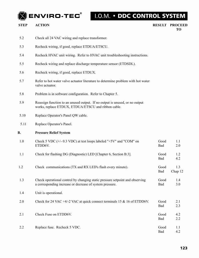
123
I.O.M. � DDC CONTROL SYSTEM STEP ACTION RESULT PROCEED
TO
5.2 Check all 24 VAC wiring and replace transformer.
5.3 Recheck wiring, if good, replace ETDUA/ETSCU.
5.4 Recheck HVAC unit wiring. Refer to HVAC unit troubleshooting instructions.
5.5 Recheck wiring and replace discharge temperature sensor (ETDSDL).
5.6 Recheck wiring, if good, replace ETDUX.
5.7 Refer to hot water valve actuator literature to determine problem with hot watervalve actuator.
5.8 Problem is in software configuration. Refer to Chapter 5.
5.9 Reassign function to an unused output. If no output is unused, or no outputworks, replace ETDUX, ETDUA/ETSCU and ribbon cable.
5.10 Replace Operator's Panel QW cable.
5.11 Replace Operator's Panel.
B. Pressure Relief System
1.0 Check 5 VDC (+/- 0.3 VDC) at test loops labeled "+5V" and "COM" on Good 1.1ETDD6V. Bad 2.0
1.1 Check for flashing DG (Diagnostic) LED [Chapter 6, Section B.3]. Good 1.2Bad 4.2
1.2 Check communications (TX and RX LED's flash every minute). Good 1.3Bad Chap 12
1.3 Check operational control by changing static pressure setpoint and observing Good 1.4a corresponding increase or decrease of system pressure. Bad 3.0
1.4 Unit is operational.
2.0 Check for 24 VAC +4/-2 VAC at quick connect terminals 15 & 16 of ETDD6V. Good 2.1Bad 2.3
2.1 Check Fuse on ETDD6V. Good 4.2Bad 2.2
2.2 Replace fuse. Recheck 5 VDC. Good 1.1Bad 4.2

124
DDC CONTROL SYSTEM � I.O.M.STEP ACTION RESULT PROCEED
TO
2.3 Check for correct line voltage (CAUTION: May be lethal). Good 4.1Bad 4.0
3.0 Control Sequence is BTC-01: 3.1Control Sequence is BTC-02: 3.7
3.1 Remove wires going to BPV-01 from quick connect terminals 6 and 7 of Good 3.2ETDD6V circuit board. Touch the term. 7 wire to terminal 15 and verify Bad 4.3BPV-01 damper closes: touch the term. 6 wire to terminal 15 and verifyBPV-01 damper opens.
3.2 For Multiple Relief Terminal Systems, Repeat 4.1, using terminals 10 & 11 Good 3.3(open and close) for the 2nd Relief Terminal (BPV-02), or terminals 12 & 13 Bad 4.3(open and close) for the 3rd Relief Terminal (also BPV-02).
3.3 Reconnect actuator wires. Remove tubing from flow transducer on the circuit Good 3.4board and verify 5 VDC (+/- 0.3 VDC) between wire loops labeled "TP3" Bad 4.2("VF") and "COM".
3.4 Using a short length of tubing, gently blow through the "HI" side of the transducer Good 3.5transducer and verify voltage between wire loops labeled "TP3" ("VF") and Bad 4.2and "COM" approaches 0 VDC.
3.5 Check tubing from static pressure sensor to flow transducer on circuit board for Good 3.6leaks, kinks and connection to "HI" side. Bad 4.4
3.6 Make sure inlet of static pressure sensor is pointing into direction of airflow. Good 1.4Bad 4.5
3.7 Remove the connections from J3 of the ETDD6 circuit board. Using the "Debug" Good 4.6mode of the VTMON program [Chapter 5, Section F.5] and the "Alt" commands Bad 4.2[Chapter 5, Auxiliary Commands and "Help" screens, Section 2], set the analogoutput to 0 VDC (Alt 7), 5 VDC (Alt 3) and 10 VDC (Alt 6) and verify that thesevoltages are present at the analog output.
4.0 Correct incoming voltage problem.
4.1 Check all 24 VAC wiring and replace transformer.
4.2 Recheck wiring, if good, replace ETDD6V.
4.3 Recheck wiring, if good, replace failed actuator.
4.4 Correct tubing problems.
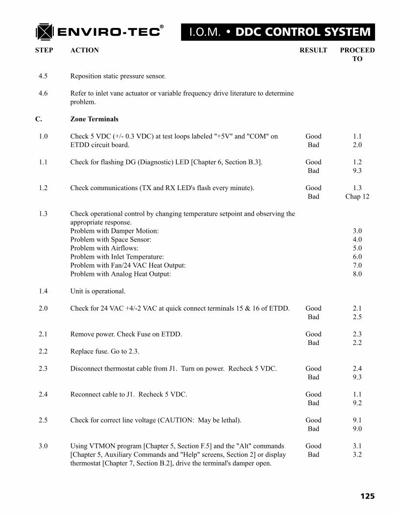
125
I.O.M. � DDC CONTROL SYSTEMSTEP ACTION RESULT PROCEED
TO
4.5 Reposition static pressure sensor.
4.6 Refer to inlet vane actuator or variable frequency drive literature to determineproblem.
C. Zone Terminals
1.0 Check 5 VDC (+/- 0.3 VDC) at test loops labeled "+5V" and "COM" on Good 1.1ETDD circuit board. Bad 2.0
1.1 Check for flashing DG (Diagnostic) LED [Chapter 6, Section B.3]. Good 1.2Bad 9.3
1.2 Check communications (TX and RX LED's flash every minute). Good 1.3Bad Chap 12
1.3 Check operational control by changing temperature setpoint and observing theappropriate response.Problem with Damper Motion: 3.0Problem with Space Sensor: 4.0Problem with Airflows: 5.0Problem with Inlet Temperature: 6.0Problem with Fan/24 VAC Heat Output: 7.0Problem with Analog Heat Output: 8.0
1.4 Unit is operational.
2.0 Check for 24 VAC +4/-2 VAC at quick connect terminals 15 & 16 of ETDD. Good 2.1Bad 2.5
2.1 Remove power. Check Fuse on ETDD. Good 2.3Bad 2.2
2.2 Replace fuse. Go to 2.3.
2.3 Disconnect thermostat cable from J1. Turn on power. Recheck 5 VDC. Good 2.4Bad 9.3
2.4 Reconnect cable to J1. Recheck 5 VDC. Good 1.1Bad 9.2
2.5 Check for correct line voltage (CAUTION: May be lethal). Good 9.1Bad 9.0
3.0 Using VTMON program [Chapter 5, Section F.5] and the "Alt" commands Good 3.1[Chapter 5, Auxiliary Commands and "Help" screens, Section 2] or display Bad 3.2thermostat [Chapter 7, Section B.2], drive the terminal's damper open.

126
DDC CONTROL SYSTEM � I.O.M.STEP ACTION RESULT PROCEED
TO
3.1 Using VTMON program or display thermostat, drive the terminal's damper Good 5.0closed. Bad 3.2
3.2 Measure the voltage across the motor terminals. Verify 1-3 VDC. Good 3.3Bad 9.3
3.3 Actuator is stalled. Loosen set screws from damper shaft and drive open and Good 9.9closed. Bad 9.7
4.0 If space sensor is an ETTS (Regular Thermostat), go to 4.2. Check if ETDIS Good 4.1(Display Thermostat) display is lit. Bad 4.3
4.1 Check function of buttons [Chapter 7, Section B.1]. Good 4.5Bad 4.3
4.2 If setpoints are locked [Chapter 5, Zone (Address) - User Settings screen, Good 4.5Section 2.a.], go to 4.5. Turn setpoint dial and verify setpoint changes using Bad 4.3VTMON program.
4.3 Remove space sensor from wall and connect to zone control using a known Good 9.10working QW cable. Recheck display and buttons (ETDIS) or setpoint (ETTS). Bad 4.4
4.4 Connect a known working space sensor through QW6 cable. Good 9.5Bad 9.3
4.5 Using VTMON program, display thermostat, or SCU Operator's Panel, verify Good 9.11thermostat temperature reading is same as actual temperature. Bad 4.6
4.6 Reading incorrect by less than 10 F: 4.7Reading incorrect by more than 10 F or at limit of range: 9.5
4.7 Using VTMON program, display thermostat, or SCU Operator's Panel, correctthermostat temperature reading [Chapter 8, Section A].
5.0 Remove tubing from flow transducer on circuit board and verify 5 VDC Good 5.1(+/- 0.3 VDC) between wire loops labeled "TP3" ("VF") and "COM". Bad 9.3
5.1 Using a short length of tubing, gently blow through the "HI" side of the Good 5.2transducer and verify voltage between wire loops labeled "TP3" ("VF") and Bad 9.3"COM" approaches 0 VDC.
5.2 Check tubing from flow probe to flow transducer on circuit board for leaks, Good 9.3kinks and connection to "HI" side. Bad 9.8
6.0 Reading incorrect by less than 10 F: 6.1Reading incorrect by more than 10 F or at limit of range: 6.2
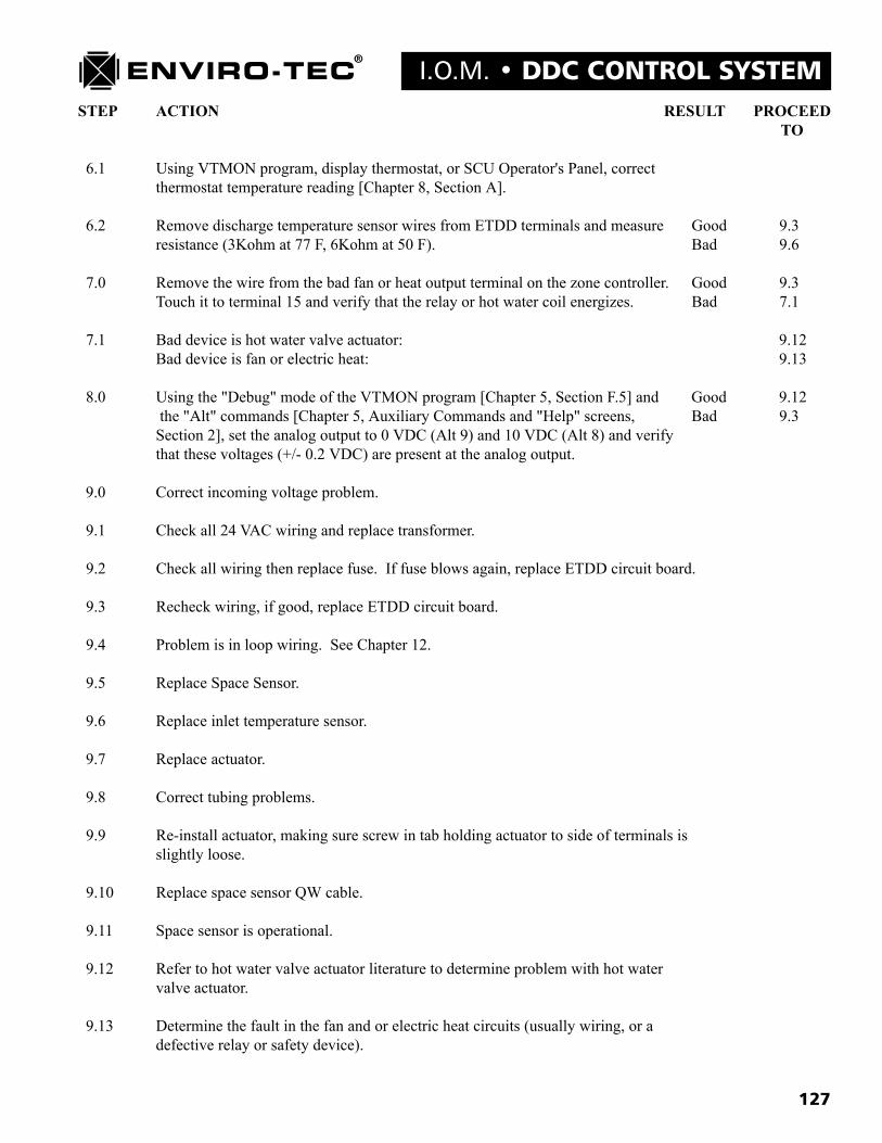
127
I.O.M. � DDC CONTROL SYSTEMSTEP ACTION RESULT PROCEED
TO
6.1 Using VTMON program, display thermostat, or SCU Operator's Panel, correctthermostat temperature reading [Chapter 8, Section A].
6.2 Remove discharge temperature sensor wires from ETDD terminals and measure Good 9.3resistance (3Kohm at 77 F, 6Kohm at 50 F). Bad 9.6
7.0 Remove the wire from the bad fan or heat output terminal on the zone controller. Good 9.3Touch it to terminal 15 and verify that the relay or hot water coil energizes. Bad 7.1
7.1 Bad device is hot water valve actuator: 9.12Bad device is fan or electric heat: 9.13
8.0 Using the "Debug" mode of the VTMON program [Chapter 5, Section F.5] and Good 9.12 the "Alt" commands [Chapter 5, Auxiliary Commands and "Help" screens, Bad 9.3Section 2], set the analog output to 0 VDC (Alt 9) and 10 VDC (Alt 8) and verifythat these voltages (+/- 0.2 VDC) are present at the analog output.
9.0 Correct incoming voltage problem.
9.1 Check all 24 VAC wiring and replace transformer.
9.2 Check all wiring then replace fuse. If fuse blows again, replace ETDD circuit board.
9.3 Recheck wiring, if good, replace ETDD circuit board.
9.4 Problem is in loop wiring. See Chapter 12.
9.5 Replace Space Sensor.
9.6 Replace inlet temperature sensor.
9.7 Replace actuator.
9.8 Correct tubing problems.
9.9 Re-install actuator, making sure screw in tab holding actuator to side of terminals isslightly loose.
9.10 Replace space sensor QW cable.
9.11 Space sensor is operational.
9.12 Refer to hot water valve actuator literature to determine problem with hot watervalve actuator.
9.13 Determine the fault in the fan and or electric heat circuits (usually wiring, or adefective relay or safety device).

128
DDC CONTROL SYSTEM � I.O.M.
Chapter 12ENVIRO-TEC DDC CONTROL SYSTEM COMMUNICATIONS TROUBLESHOOTING
If all the instructions regarding communications wiring presented previously in this manual are followed, it is unlikely there will be aproblem with communications. However, since one error in wiring the communications loop can cause all units to fail to communi-cate, troubleshooting the loop may first seem to be a difficult and confusing task. This need not be the case, however, if the task isapproached in a logical and orderly manner.
A. Type of ProblemThere are several types of communications related problems which require different methods to troubleshoot.Use of the VTMON program is highly recommended for troubleshooting all of these problems.1. Communications solid to some or most units, but one or more do not communicate at all. See Section C.2. Individual units will respond with direct connection (through space sensor), but no other units can be accessed.
See Sections B, C and D.3. Units respond occasionally, but erratically and slowly. See Sections B, C and D.4. Unit won�t respond through space sensor connection. See Section F.
B. Wiring problemsAs discussed previously in this manual, no units should be plugged into the loop until a pre-power check is performed. Also,communications should be checked after each unit�s communications plug is connected. If a unit is attached, and suddenlyall communications is lost, it may be a wiring problem rather than a problem with the unit itself. Check to make sure the plughas been correctly inserted into the board: plugging it in backwards will definitely cause problems with all communications.Also, if the plug is wired backward, communications will function until the backwards plug is connected, then it will cease.Wiring the communications loop in a star or stub configuration, or leaving long lengths of untwisted/unshielded wire atcommunications connectors can cause erratic communications. The only solution for problems caused by this type of poorinstallation is to rewire the loop and/or re-terminate the cable at the controls.
C. Voltage CheckIf communications problems persist, measure the DC voltage from red or white to shield, and black to shield. When commu-nications is not occurring (TXD and RXD LED�s on ETDUA/ETSCU are not flashing), these should be 3.3 and 1.7 VDC,respectively (+/- 0.2 VDC). NOTE: If the loop in question is a zone bus, it must be plugged into ETDUA/ETSCU for thistest to be valid.
D. Splitting MethodIf there are only a few units on a loop, they may be unplugged one at a time until the problem unit is found; however, witha larger number of units on a loop this procedure would be extremely time consuming. To isolate the problem, split the loopin half: if communications resumes with the connected units, the problem resides in the disconnected half. If communica-tions does not resume, the problem resides in the connected half of the loop. Keep splitting the loop in half until the problemunit is found.EXAMPLE: A loop of sixteen zone controllers and an SCU shows no communications. Connect a PC to the Operator�sPanel and run the VTMON program. Disconnect the cable leading from the eighth unit on the loop to the ninth unit on theloop. If communications do not result with the first eight units, disconnect the cable leading from the fourth unit to the fifthunit. Assuming the first four units now begin communicating, this means that one of units which are fifth through eighth onthe loop has a problem. Reconnect the cable leading from the fourth to the fifth unit, and disconnect the cable leading fromthe sixth to the seventh unit. If the first six units are communicating, then the problem lies with the seventh or eighth unit.Reconnect all disconnected wires, making sure that wiring is done correctly. Unplug the seventh unit. If all units except theseventh now communicate, the seventh unit should be replaced.
E. Zone Bus Communications Problems with Individual UnitsIf high voltage has been applied to the loop, one or more of the RS485 IC�s may have been damaged. This device is the eight(8) pin integrated circuit located between the LED�s and the loop communication connectors. It is inserted in a socket so itmay be replaced without requiring the whole circuit board to be replaced. An RS485 IC from a known working (andcommunicating) board may be used to determine if this is the problem.Power should be removed from both the donor board and the problem board before attempting this replacement. Wheninserting the IC, make sure not to bend any of it�s pins. Also make sure the dot on the IC is closest to the end of the socketwhere the decoupling capacitor (small, oval, yellow or blue component) is located. If it is necessary to order one of theseIC�s, the ETI part number is 8905, and the Texas Instruments� part number is SN75176P.If the unit in question still does not communicate, after the RS485 IC has been replaced, the unit itself should be replaced.
F. Space Sensor Communication ProblemsRemove the space sensor QW cable and connect directly to the space sensor connection (J2) on the zone controller. If theunit still does not communicate, replace the zone controller. If it does communicate, the space sensor or QW cable isdefective. Use a know good space sensor to determine which component to replace.


