38
DDS, DKS, DDC and MDD Digital intelligent AC servo drives DOK-DIAX02-DDS+DKS+DDC-WAR1-EN-P Notes on Fault Clearance mannesmann Rexroth engineering Indramat 259905

DDS, DKS, DDC and MDDDigital intelligent AC servo drives
DOK-DIAX02-DDS+DKS+DDC-WAR1-EN-P
Notes on Fault Clearance
mannesmannRexroth
engineering
Indramat259905

2• DOK-DIAX02-DDS+DKS+DDC-WAR1-EN-E1,44 • 12.96
About this documentation
DDS, DKS, DDC and MDD - digital intelligent AC servo drives
Notes on Fault Clearance
DOK-DIAX02-DDS+DKS+DDC-WAR1-EN-E1,44
• Mappe 11b• DDDD-ST.pdf• 209-0069-4357-01
This electronic document is based on the hardcopy document with documentdesig.: 209-0069-4357-01 EN/ 11.94
It is intended as a quick reference manual for trained maintenance personnel
• to enable rapid identification of fault sources,
• as an effective guide for rapid fault clearance, and,
• for rapid and effective consulting with the machine manufacturer orINDRAMAT customer service representative.
This manual is intended for storage in the control cabinet where it should beeasily accessible to maintenance personnel.
If a drive component has to be replaced and the machine or plantsubsequently restarted, refer to the relevant Applications Manualfor the installed drive.
An applications manual can be obtained from the nearest service represenativeupon request (see section 3).
Titel
Type of documentation:
Documenttype
Internal file reference
Reference
This documentationis used:
© INDRAMAT GmbH, 1994Copying of this document, and giving it to others and the use or communicationof the contents thereof, are forbidden without express authority. Offenders areliable to the payment of damages. All rights are reserved in the event of thegrant of a patent or the registration of a utility model or design. (DIN 34-1)
The electronic documentation (E-doc) may be copied as often as needed ifsuch are to be used by the consumer for the purpose intended.
INDRAMAT GmbH • Bgm.-Dr.-Nebel-Straße 2 • D-97816 LohrTelefon 0 93 52 / 40-0 • Tx 689421 • Fax 0 93 52 / 40-48 85Dept ENA (VS, FS)
All rights reserved with respect to the content of this documentation and theavailability of the products.
Copyright
Publisher
Validity
Designation of documentation Release- Coments
up to present edition date
209-0069-4357-01 EN/11.94 Nov./94 First Edition
DOK-DIAX02-DDS+DKS+DDC-WAR1-EN-E1,44 Dez./96 Introduction of document type
Änderungsverlauf
Supplementaryliterature
3• DOK-DIAX02-DDS+DKS+DDC-WAR1-EN-E1,44 • 12.96
Table of Contents
PageTable of Contents
1. General information 5
2. Status indications 7
2.1. H1 status indicator (on the drive controller) .....................................7
2.2 H2 status indicator (on SERCOS interface module) ......................27
2.3 Command errors ............................................................................30
3. List of INDRAMAT service representatives 33
4. Index 35

4• DOK-DIAX02-DDS+DKS+DDC-WAR1-EN-E1,44 • 12.96
5• DOK-DIAX02-DDS+DKS+DDC-WAR1-EN-E1,44 • 12.96
1. General information
1. General information
This manual explains the meanings of the alphanumeric displays on statusindicator H1 (on the drive controller) and H2 (on the SERCOS interfacemodule). It also helps diagnose any existing problem and quickly clear it.
For quick accessing, all display codes are alphanumerically arranged in thesection "Status Indications".
In the event that you cannot clear a fault yourself, please contact yourINDRAMAT customer service representative. All addresses are listed in thesection "INDRAMAT customer representatives".
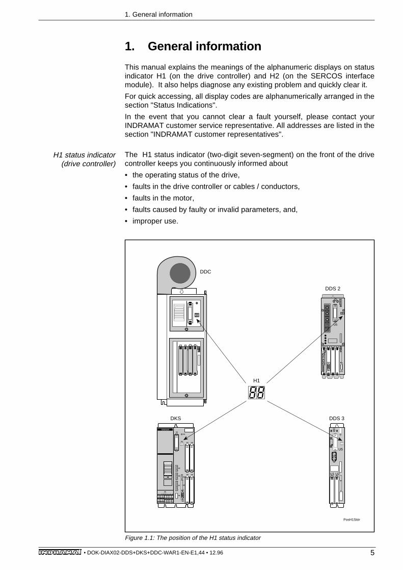
The H1 status indicator (two-digit seven-segment) on the front of the drivecontroller keeps you continuously informed about
• the operating status of the drive,
• faults in the drive controller or cables / conductors,
• faults in the motor,
• faults caused by faulty or invalid parameters, and,
• improper use.
Figure 1.1: The position of the H1 status indicator
U5
SYSTEMKONFIGURATION
A1VU A3A2W
H1
X4
X2
U5
U2
X5
U4
U1 U3
X61
5
X9
1
6
1
7
X8
S1
X7
1
10
1
11
X3
SYSTEMKONFIGURATION
U5
U1 U2
DKS
DDC
DDS 2
DDS 3
PosH1Stör
H1
H1 status indicator(drive controller)
6• DOK-DIAX02-DDS+DKS+DDC-WAR1-EN-E1,44 • 12.96
1. General information
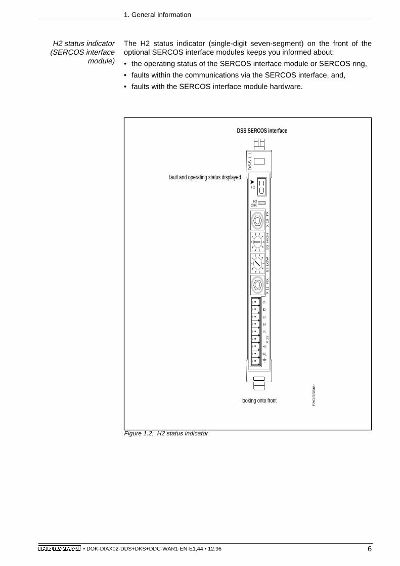
The H2 status indicator (single-digit seven-segment) on the front of theoptional SERCOS interface modules keeps you informed about:
• the operating status of the SERCOS interface module or SERCOS ring,
• faults within the communications via the SERCOS interface, and,
• faults with the SERCOS interface module hardware.
H2 status indicator(SERCOS interface
module)
Figure 1.2: H2 status indicator
fault and operating status displayed
FA
DS
SS
tör
looking onto front
H2
DS
S 1
.1
H3CHK
+UL
0VL
E4
E5
E3
E2
E1
X 1
2X
11
X 1
0S
3L
OW
S2
RX
T
XH
IGH
0
12 3
4
5
6
78
9
0
12 3
4
5
6
78
9
DSS SERCOS interface

7• DOK-DIAX02-DDS+DKS+DDC-WAR1-EN-E1,44 • 12.96
2. Status indications
2. Status indications
The display codes of a status indicator are arranged alphanumerically. Thefollowing is available for each code:
• meaning,
• possible causes, and,
• remedial actions (in the case of either faults or warnings)
Displays on H1 (on the drive controller): see section 2.1Displays on H2 (on the SERCOS interface module): see section 2.2
After clearing a fault, it is necessary to first cancel the error message beforethe drive can be ready to operate.
An error message is cancelled as follows:
• via the controller, if a SERCOS interface module is used,
• via the fault clearance key "S1" on the drive, if the ANALOG interfacemodule is used, and,
• via the fault clerance key "S1" on the drive, and the "CL" key on the controlunit's control panel if a single-axis positioning module (DLC) is used.
2.1. H1 status indicator (on the drive controller)
Clearing data RAM (temporary operating status)Should the drive controller stall in this display, then the drive controller mustbe replaced. (See relevant documentation in Applications Manual.)
Checking and, if necessary, automatic clearing of the parameter memory(EEPROM) in the software module (temporary operating status)This is displayed on new software modules for approximately 15 seconds.Should the drive controller stall in this display, then the drive controller mustbe replaced. (See relevant documentation in Applications Manual.)
Loading program (temporary operating status)The firmware is loaded into programm memory from EPROM .Should the drive controller stall in this display, then the drive controller mustbe replaced. (See relevant documentation in Applications Manual.)
The power source on the drive controller must be ready to operatebefore the status displays can be used for fault diagnostics.
Cancelling a fault

8• DOK-DIAX02-DDS+DKS+DDC-WAR1-EN-E1,44 • 12.96
2. H1 status indications (on the drive controller)
Checking Hardware (temporary operating status)Checking data RAM.Should the drive controller stall in this display, then the drive controller mustbe replaced. (See relevant documentation in Applications Manual.)
Initializing hardware (temporary operating status)Should the drive controller stall in this display, then the drive controller mustbe replaced. (See relevant documentation in Applications Manual.)
Initializing software (temporary operating status)Data from EEPROM are copied onto the RAM and verified to see whether thelimiting values have been maintained.Should the drive controller stall in this display, then the drive controller mustbe replaced. (See relevant documentation in Applications Manual.)
Initializing the software (temporary operating status)(Oscillator functions and feedback codes.)Should the drive controller stall in this display, then the drive controller mustbe replaced. (See relevant documentation in Applications Manual.)
Initializing the software (temporary operating status)(reading DSF data)Should the drive controller stall in this display, then the drive controller mustbe replaced. (See relevant documentation in Applications Manual.)
Initializing the SERCOS (temporary operating status)Should the drive controller stall in this display, then the drive controller mustbe replaced. (See relevant documentation in Applications Manual.)
Watchdog (fault message)
Cause 1: Software module not installed or defective.
Install or replace the software module.
Cause 2: Processor defective.
Replace the drive controller.
Remedy
Remedy

9• DOK-DIAX02-DDS+DKS+DDC-WAR1-EN-E1,44 • 12.96
2. H1 status indicator (on the drive controller)
Drive ready (operating status)The control and power sections of the drive are ready. Power is on. Driveenable signal from the NC control unit has not been applied.
Drive enable signal (operating status)The drive enable signal has been applied and the drive activated. The drivewill follow the velocity command.
Drive halt (operating status)The drive is braked to a stop at the acceleration rate set in the parameters (IDno. 00136 for SERCOS) and remains under control.
Starting lock-out (operating status)The power output stage has been locked. This signal ensures safe torquedisabling of the drive independently of the current operating status of the drivepackage (see Applications Manual).
Ready for input power (operating status)The control section of the drive is ready for powering up.
E-STOP (Emergency stop) (operating status)The E-STOP has been activated. The AC servo drive will be shut downaccording to the set error reaction (see Applications Manual).
Park axis command (operating status)The NC control unit has issued this command. The drive controller has beendeactivated.
Phase 0 (temporary operating status)The drive is in Phase 0 and is waiting for phase progression from Phase 0 toPhase 1. If the drive controller stalls in this display, then there is a problem withphase progression.For further diagnostics, please check the definition of the display presently onH2 (on the SERCOS interface module) in the relevant section of this manual.
Phase 1 (temporary operating status)The drive is in Phase 1 and is waiting for phase progression from Phase 1 toPhase 2. If the drive controller stalls in this display, then there is a problem withphase progression.For further diagnostics, please check the definition of the display presently onH2 (on the SERCOS interface module) in the relevant section of this manual.

10• DOK-DIAX02-DDS+DKS+DDC-WAR1-EN-E1,44 • 12.96
2. H1 status indicator (on the drive controller)
Phase 2 (temporary operating status)Before the NC control unit progresses to Communications Phase 3, the drivecontroller checks the parameters entered for completeness and for compliancewith the input limits (but not for logical accuracy!). If the controller detects anyinvalid parameter values, it will prevent progression of the communicationsphase.
Does not progress to Phase 3
The "ID no. List of Invalid Operation Data for CommunicationsPhase 2" (ID no. S-0-0021) contains parameters that are recognizedas invalid prior to transition to Communications Phase 3. Theseparameters must be run through before any progression to Phase3 is possible. Check the parameters.
Phase 3 (temporary operating status)Before the control unit progresses to Communications Phase 4, the drivecontroller checks the parameters entered for completeness and for compliancewith the input limits (but not for logical accuracy!). These parameters must berun through before any progression to Phase 4 is possible.
Does not progress to Phase 4
The "ID no. List of Invalid Operation Data for CommunicationsPhase 3" (ID.-Nr. S-0-0022) contains parameters that are recognizedas invalid prior to transition to Communications Phase 4. Theseparameters must be run through before any progression to Phase4 is possible. Check the parameters.
Double MST error shutdown (fault message)The drive has not received the master synchronization telegram for twosuccessive SERCOS cycles.
Cause 1: Error in the optical-fiber transmission cable, or excessive dampingof optical signals.
Check the optical-fiber (LWL) connections in the SERCOS ring.Check the damping in the LWL cable (maximum damping betweenTx and Rx: 12.5 dB).
Cause 2: Fault in the SERCOS interface module (general).
Replace the SERCOS interface module in the drive package.
Double MST error shutdown (fault message)The drive has not received the master synchronization telegram for twosuccessive SERCOS cycles.
For cause and remedial actions see display "01" (double MST error shutdown).
Remedy
Remedy
Remedy
Remedy

11• DOK-DIAX02-DDS+DKS+DDC-WAR1-EN-E1,44 • 12.96
2. H1 status indicator (on the drive controller)
Remedy
Remedy
Invalid communication phase shutdown (fault message)The SERCOS master module has commanded an invalid communicationphase (phase > 4).
Fault in the SERCOS master module of the NC control unit
Consult the control unit manufacturer.
Error during phase progression (fault message)Phase progression did not comply with the prescribed sequence.
For cause and remedial action see error message "03" (invalid communicationphase shutdown).
Error during phase regression (fault message)The phase did not revert to Phase 0 during regression.
For cause and remedial action see error message "03" (invalid communicationphase shutdown).
Phase progression without ready signal (fault message)The SERCOS master attempted to switch phases without waiting for thedrive's "ready" signal.
For cause and remedial action see error message "03" (invalid communicationphase shutdown).
Switching to uninitialized operating mode (fault message)
No operating mode defined in the activated operating mode parameter.
Enter the desired operating mode in the activated operating modeparameter.
See control unit manual for entering the desired operating mode as well as theparameters S-0-0032 (primary operating mode) and S-0-0033 to S-0-0035(secondary operating modes 1 through 3) in the SERCOS interface manual.
Permissible operating modes are:
• torque loop• velocity loop• position loop with position feedback value 1• position loop with position feedback value 2• position loop with position feedback value 1, lagless• position loop with position feedback value 2, lagless• position loop with command filter with lag error• position loop with command filter, lagless

12• DOK-DIAX02-DDS+DKS+DDC-WAR1-EN-E1,44 • 12.96
2. H1 status indicator (on the drive controller)
Motor overtemperature shutdown (fault message)The motor temperature has risen above the permissible level. The drivecontroller then a emitted a thirty-second warning: 51 "motor overtemperaturewarning". The drive then shut down according to the selected error reaction,while signalling the above error message (see selection options for errorreactions in the Application Manual).
Cause 1: The motor was overloaded. The effective torque demanded fromthe motor was above the permissible nominal torque for too long.
Check motor dimensioning. For plants which have been in operationfor some time, check whether the drive conditions have changed(e.g., contamination, friction, moved masses, etc.).
Cause 2: Earthing or short-circuit in the conductor for motor temperaturemonitoring.
Check the motor temperature monitoring conductor X 6/1 and X 6/2for earth-short or breaks.
Remedy
Bleeder overtemperature shutdown (fault message)
Excessively high continuous regenerative power.
Change the process cycle or choose a DKS with a higher ratedcurrent.
Remedy
Remedy
Remedy
Remedy
Drive overtemperature shutdown (fault message)Overtemperature was detected in the power output stage of the DDS 2.1 drivecontroller. The drive controller then emitted a thirty-second warning: 50"amplifier overtemperature warning", and shut itself down according to theselected error reaction, while signalling the above error message.
Cause 1: Failure of internal cooling system of unit.
Replace the drive controller.
Cause 2: Failure of the cabinet air conditioning.
Restore the cabinet air conditioning function.
Cause 3: Incorrectly dimensioned heat dissipation of the cabinet airconditioning.
Check the cabinet dimensioning.
Remedy
13• DOK-DIAX02-DDS+DKS+DDC-WAR1-EN-E1,44 • 12.96
2. H1 status indicator (on the drive controller)
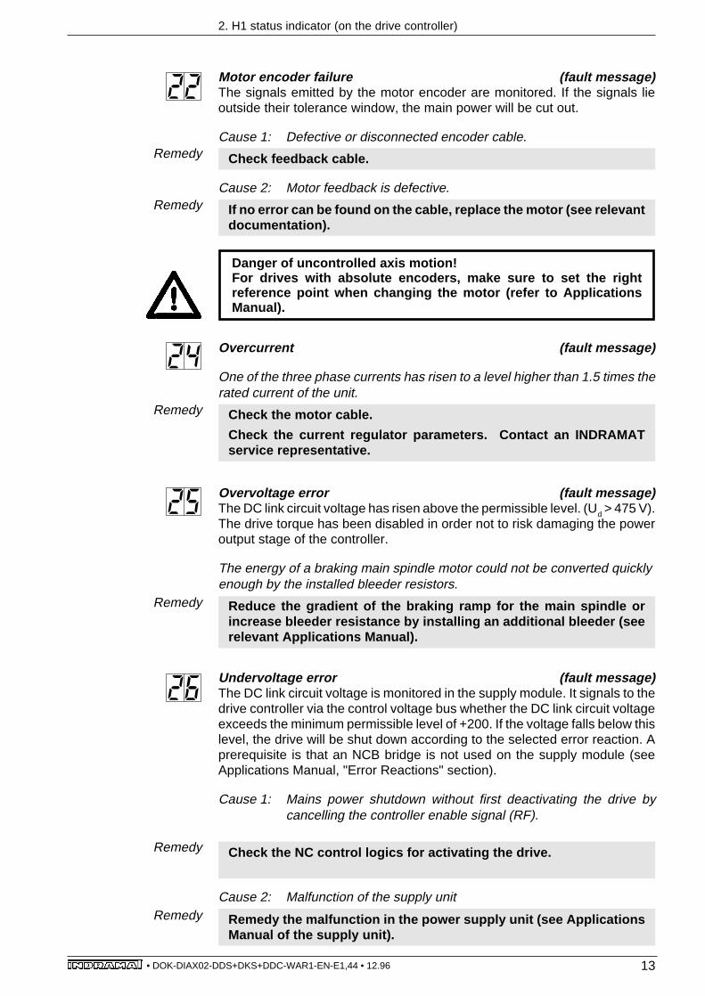
Motor encoder failure (fault message)The signals emitted by the motor encoder are monitored. If the signals lieoutside their tolerance window, the main power will be cut out.
Cause 1: Defective or disconnected encoder cable.
Check feedback cable.
Cause 2: Motor feedback is defective.
If no error can be found on the cable, replace the motor (see relevantdocumentation).
Danger of uncontrolled axis motion!For drives with absolute encoders, make sure to set the rightreference point when changing the motor (refer to ApplicationsManual).
Remedy
Remedy
Overcurrent (fault message)
One of the three phase currents has risen to a level higher than 1.5 times therated current of the unit.
Check the motor cable.
Check the current regulator parameters. Contact an INDRAMATservice representative.
Remedy
Overvoltage error (fault message)The DC link circuit voltage has risen above the permissible level. (Ud > 475 V).The drive torque has been disabled in order not to risk damaging the poweroutput stage of the controller.
The energy of a braking main spindle motor could not be converted quicklyenough by the installed bleeder resistors.
Reduce the gradient of the braking ramp for the main spindle orincrease bleeder resistance by installing an additional bleeder (seerelevant Applications Manual).
Remedy
Undervoltage error (fault message)The DC link circuit voltage is monitored in the supply module. It signals to thedrive controller via the control voltage bus whether the DC link circuit voltageexceeds the minimum permissible level of +200. If the voltage falls below thislevel, the drive will be shut down according to the selected error reaction. Aprerequisite is that an NCB bridge is not used on the supply module (seeApplications Manual, "Error Reactions" section).
Cause 1: Mains power shutdown without first deactivating the drive bycancelling the controller enable signal (RF).
Check the NC control logics for activating the drive.
Cause 2: Malfunction of the supply unit
Remedy the malfunction in the power supply unit (see ApplicationsManual of the supply unit).
Remedy
Remedy
14• DOK-DIAX02-DDS+DKS+DDC-WAR1-EN-E1,44 • 12.96
2. H1 status indicator (on the drive controller)
Excessive deviation (fault message)The drive could not follow the given command value and reacted according tothe selected error reaction.
Cause 1: The command signal exceeded the acceleration potential of thedrive.
Check the parameter "bipolar torque limit value" (no. S-0-0092) andset to the maximum permissible value for the application (see thesection on "Limit Values" in the Applications Manual), or reduce theacceleration command in the control unit (see the control unitmanual).
Cause 2: The axis has jammed.
Check the mechanics and remedy any jamming.
Cause 3: Error in the drive parameters.
Check the drive parameters (see section "Velocity Loop" in therelevant Applications Manual).
Cause 4: S-0-0159 monitoring window incorrectly parametrized.
To check parameter S-0-0159, see section on Operating Modes /Monitoring of Control Loops in the relevant Applications Manual.
Cause 5: Main power was switched off without the controller enable signalhaving been cancelled. Possible cause is an error in one AC servodrive in the common supply module.
Check AC servo drive for errors other than denoted by message "28".
Remedy
Remedy
Remedy
Remedy
Remedy
Travel limit switch is exceeded (fault message)
The drive has received a command value which would move the axis outsidethe permitted travel range.
Check position limit parameters S-0-0049 and S-0-0050 (seeApplications Manual, section on "Limit Values") or check the softwarelimits in the control unit.
Remedy
Command error (fault message)Error messages occurring while a command is being executed are displayedas a collective diagnostic message on the H2 status indicator (32, flashing).The exact error message can be called up via the SERCOS parameter S-0-0095 "diagnostic messages". The definition of all emitted errors is listed insection 2.3 "Command Errors".

15• DOK-DIAX02-DDS+DKS+DDC-WAR1-EN-E1,44 • 12.96
2. H1 status indicator (on the drive controller)
External power supply error (fault message)Different optional plug-in modules have DC-decoupled inputs and outputs. Anexternal power supply must be applied for proper operation of these inputs andoutputs.
The voltage lies above the permissible level.
Check the external power supply.Remedy
Figure 2.1: Voltage tolerances
Error in internal software synchronization (fault message)
Faulty communication between the drive's processor and the SERCOSinterface module
Replace the SERCOS interface module or the drive controller(see relevant Applications Manual).
Remedy
Invalid reference cam position (fault message)
The position of the reference cam relative to the null point of the motor encoderis outside the permissible range.
For software status ≤ DSM2.1-S01.9:Parameter P-0-0020 gives the offset of the home switch flank to theoptimum point. Shift the reference cam by this amount, then initiatea drive-generated homing procedure.For software status ≥ DSM2.1-S01.10:Load the value displayed in parameter P-0-0020 into parameter S-0-0299.
For the tolerance range of the permissible home switch flank positions in theencoder cycle, see Figure 1.2.:
Remedy
Figure 2.2: Positioning the reference cam.
PosRefStör
0° 90°
optimum referencecam position
permissible tolerance range
α cykl Position detection range of one encoder cycle
360°
180° = α zykl12
180°
Description unit minimum rated maximum
External operating voltage +UL V 18 24 32
Current consumption of external +UL
mA 100

16• DOK-DIAX02-DDS+DKS+DDC-WAR1-EN-E1,44 • 12.96
2. H1 status indicator (on the drive controller)
Excessive actual position difference (fault message)In the prepare phase progression command on Communications Phase 4,actual position value 2 is stored on the position feedback value, and thecyclical evaluation of both encoders is initiated. During this cyclical operation(phase 4), the position difference of both encoders is compared every 8milliseconds. If the difference is greater than one parametrized monitoringwindow (P-0-0120), then error "36" appears and the parametrized errorreaction (P-0-0007) is executed.
Cause 1: The parameter for the external encoder is incorrect (S-0-0115,S-0-0117, S-0-0118).
Check position encoder parameter (S-0-0115) and encoder resolution(S-0-0117 or S-0-0118).
Cause 2: The mechanics between the motor shaft and the external encoderare incorrectly parametrized.
Check input and output revolutions of load mechanism (S-0-0121, S-0-0122) and feed constants (S-0-0123).
Cause 3: The mechanics between motor shaft and external encoder arenot rigid (e.g., gear backlash).
Enlarge monitoring window for external encoder (P-0-0120).
Cause 4: The encoder cable is defective.
Replace the encoder cable
Cause 5: DEF 1.1 is defective.
Replace DEF 1.1.
Cause 6: Maximum input frequency of the encoder interface exceeded.
Reduce velocity.
Cause 7: External encoder not mounted to running axis.
Set monitoring window for external encoder (P-0-0120) to "0" (=monitoring disengaged).
Remedy
Remedy
Remedy
Remedy
Remedy
Remedy
Remedy
Excessive position command difference (fault message)When the drive is working in position loop mode, position command signalsarriving through the SERCOS interface are monitored.
If the velocity demanded of the drive by two successive position commandsignals is equal to or greater than the "bipolar velocity limit value", the positoncommand monitoring function will be activated. The excessive positioncommand is stored in parameter P-0-0010. The last valid position commandis stored in parameter P-0-0011 (see Applications Manual).
Compare the "bipolar velocity limit value" (ID-Nr. S-0-0091) with thevelocity stored in the part program and adapt, if necessary.
Remedy

17• DOK-DIAX02-DDS+DKS+DDC-WAR1-EN-E1,44 • 12.96
2. H1 status indicator (on the drive controller)
Remedy
Remedy
Remedy
External encoder failure: quadrant error (fault message)A hardware fault has been detected on the DLF 1.1 high-resolution positioninterface for sine signals in the external measuring system.
Cause 1: Defective encoder cable.
Replace encoder cable.
Cause 2: Interference in the encoder cable.
Lay encoder cable away from power-carrying cables.
Cause 3: Defective DLF 1.1 module.
Replace DLF 1.1 module.
Remedy
Remedy
Remedy
Commands that would move the axis still further out of range will notbe accepted by the drive. If it receives another such command, it willemit the same error message.
Travel limit switch detected (fault message)
The travel limit switch has been detected, resulting in shutdown of the relevantdrive package's power supply. The servo drive was brought to a standstill withmaximum acceleration.
1. Clear the error on the control unit.2. Reactivate the power supply.3. Move the axis back into the permissible travel range.
Invalid feedback data --> Phase 2 (fault message)Error 22 (motor encoder failure) has occurred during cyclic operation (Phase4). This error message is generated by the drive controller once the firstmessage has been cleared in Phase 4.
Defective feedback cable or feedback
Check feedback and feedback cable, repair/replace, if necessary,and clear the error in Phase 2.
External encoder failure: signals too small (fault message)For high-resolution evaluation, an external measuring system will use itsanalog signals.
The signal amplitudes are below a permissible limit.
Check the cable to the measuring system.
18• DOK-DIAX02-DDS+DKS+DDC-WAR1-EN-E1,44 • 12.96
2. H1 status indicator (on the drive controller)
External encoder failure:frequency limit exceeded (fault message)
The interface module for connection of the external measuring system mayonly be operated up to a maximum input frequency.Maximum input frequencies: DEF 1.1 = 1000 kHz
DEF 2.1 = 1000 kHzDLF 1.1 = 150 kHz
Maximum input frequency exceeded.
Reduce the velocity.Remedy
Error in detecting the marker of the external encoder (fault message)
Cause 1: Defective DLF 1.1 module.
Replace DLF 1.1 module.
Cause 2: Error in detecting the marker of the external encoder.
Contact an INDRAMAT service representative as the installed encoderis not compatible with the evaluation electronics.
Remedy
Remedy
Low absolute encoder battery voltage (fault message/ warning)Absolute encoders incorporating a battery in the feedback are voltage-monitored. This mesage is emitted if the battery voltage falls below 2.8V. Theabsolute encoder will still function for roughly another four weeks.
When this period has elapsed, the absolute reference point may belost. This means danger of uncontrolled axis motions! Replace thebattery as soon as possible!
Battery voltage has dropped below 2.8V.
Replace with new battery (part no. 257101).Remedy
The following tools are needed to exchange the battery:
• torx screwdriver, size 10• pointed pliers• torque wrench
Danger of uncontrolled axis motions when replacing batteries!Therefore:• Switch power supply off. Secure it against being swtiched back on.• Exchange the battery while the control voltage is on! If the control voltage is switched off while the battery has been pulled, then the absolute reference point will be lost. The absolute reference point must then first be reset.
Removing the old battery:
• Using a screwdriver, remove the four torx screws (1).• Manually pull out the lid of the resolver feedback RSF with hood.• Carefully remove the battery plug (2).• Use the pointed pliers to pull the batteries out (3).
Procedure

19• DOK-DIAX02-DDS+DKS+DDC-WAR1-EN-E1,44 • 12.96
2. H1 status indicator (on the drive controller)
Putting the new battery in:
• Manually place the battery (part no. 257101) into the housing. Attention:do not pinch the battery cable!
• Re-connect the battery plug (2) to the pc board. Attention: make surepolarity is correct!
• Put lid of the resolver feedback RSF with hood back into the housing.Attention: Only one lid position is possible!
• Screw the four torx screw (1) back into place and, with the use of the torquewrench, tighten them with 1.8 Nm.
2_03RSF.tif Stör
Figure 2.3: Resolver feedback with back-up battery
3
2
1
1
Remedy
Master encoder failure (fault message)The master encoder signals are monitored. This error message is generatedwhen they move out of the tolerance range.
Cause 1: The encoder cable is faulty.
Check the encoder cable.
Cause 2: The feedback is defective.
Replace the feedback.
Cause 3: The DFF card is defective.
Replace the DFF card.
Remedy
Remedy
Remedy
Drive overtemperature warning (warning)The temperature of the heatsink in the drive controller has reached themaximum permissible level. The drive will follow the command value for 30seconds. This permits the axis to be brought to a halt by the NC control unitwithout endangering the process (e.g., completing a machining operation,retreating from an area where collisions might occur, etc.).After 30 seconds, the drive will react according to the parameter "error reaction(P-0-0007) (see relevant Applications Manual).
Cause 1: Failure of unit's internal cooling system.
Replace the drive controller.
Cause 2: Failure of the cabinet's air conditioning system.
Restore the cabinet air conditioning function.
Cause 3: Insufficiently dimensioned cabinet heat dissipation.
Check cabinet dimensioning.
Remedy
Remedy

20• DOK-DIAX02-DDS+DKS+DDC-WAR1-EN-E1,44 • 12.96
2. H1 status indicator (on the drive controller)
Motor overtemperature warning (warning)The motor has risen above the permissible temperature. The drive will followthe given command value for 30 seconds. This permits the axis to be broughtto a halt by the NC control unit without endangering the process (e.g.,completing a machining operation, retreating from an area where collisionsmight occur, etc.). After 30 seconds, the drive will react according to theparameter "error reaction" (see Applications Manual).
The motor was overloaded. The effective torque demanded from the motorwas above the permissible nominal torque for too long.
Check the motor dimensioning. For plants which have been inoperation for some time, check whether the drive conditions havechanged (e.g., contamination, friction, moved masses, etc.).
Remedy
Bleeder overtemperature warning (warning)
On reversing, the motor briefly enters the bleeder overload range.
The contact on the plug terminal block X7 closes and can thus be evaluated.If a predetermined limit is exceeded, error message 20 "bleederovertemperature shutdown" will be generated.
Bridge fuse (fault message)The current in the power transistor bridge has risen to more than twice theunit's rated current. The drive torque function is immediately disabled.
Cause 1: Short-circuit in the motor cable.
Check the motor cable for short-circuits.
Cause 2: Power section of the drive controller is defective.
Replace the drive controller, if necessary.
Remedy
Remedy
Overcurrent: short to ground (fault message)The sum of the phase currents is monitored. During normal operation, the sum= 0. The earth connection fuse will react when the sum of the currents risesabove 0.5 x IN.
Defective motor cable or earth short in the motor.
Check motor cable and motor for shorting to earth and replace, ifnecessary (see relevant documentation when replacing).
Remedy
21• DOK-DIAX02-DDS+DKS+DDC-WAR1-EN-E1,44 • 12.96
2. H1 status indicator (on the drive controller)
Erroneous internal hardware synchronization (fault message)The pulse width modulator of the drive controller is synchronized by a phase controlloop. The synchronization is monitored and the above error message signalledwhen a fault is detected.
Cause 1: Faulty synchronization of the pulse width modulator.
Replace the unit and send it in for checking.
Cause 2: Error in MST from master (NC control unit).
Check transmission starting time. (Consult the manufacturer of theNC control unit.)
Remedy
Remedy
Brake error (fault message)For MDD motors with integral brakes, the drive controller pilots the brake. Thebrake current is monitored. If it lies outside the permissible range, the aboveerror message will be signalled.
Cause 1: The supply voltage for the holding brake has not been properlyconnected or lies outside the tolerance window (24 V, ±10 %).
Check voltage supply.
Cause 2: Motor cable incomplete or wrongly connected (reverse polarity).
Check motor cable.
Cause 3: Defective holding brake.
Replace the motor (see relevant documentation).
Cause 4: Defective drive controller.
Replace the controller.
Remedy
Remedy
Remedy
Remedy
±15 V error (fault message)The controller has detected a vault in the ±15 V supply.
Cause 1: Defective control voltage bus cable.
Check and, if necessary, replace the control voltage bus cable or plugconnector.
Cause 2: Defective supply module.
Check the power supply module (see Applications Manual for supplymodule).
Remedy
Remedy

22• DOK-DIAX02-DDS+DKS+DDC-WAR1-EN-E1,44 • 12.96
Remedy
Remedy
2. H1 status indicator (on the drive controller)
+24 V error (fault message)The controller has detected a fault in the +24 V supply.
Cause 1: Defective control voltage bus cable.
Check and, if necessary, replace the control voltage bus cable or plugconnector.
Cause 2: Overload in the 24 V voltage supply.
Check the 24 V voltage supply in the power supply module.
Cause 3: Defective supply module.
Check the power supply module (see Applications Manual for supplymodule).
Cause 4: Short in the E-stop circuit.
Check the E-stop circuit for shorting.
Remedy
Remedy
Remedy
Remedy
±10 V error (fault message)The supply voltage to the current sensors is faulty.
Defect in the drive controller.
Replace the drive controller.Remedy
+8 V error (fault message)The supply voltage to the encoder systems is faulty.
Short-circuit in motor encoder cable or in cable for external encoders.
Check cables and replace, if necessary.
Power supply to driver stage. (fault message)The voltage supply to the driver stages is faulty.
Defect in the drive controller.
Replace drive controller.
Pattern data transmission time invalid (fault message)The pattern calculator is not sending the pattern data synchronously to thelead axis position.
Wrong trigger signals for sending pattern data.
Check trigger signal (consult NC control unit manufacturer).
Remedy

23• DOK-DIAX02-DDS+DKS+DDC-WAR1-EN-E1,44 • 12.96
2. H1 status indicator (on the drive controller)
Absolute encoder error (fault message)When a DDS with absolute encoder motor (multiturn) is switched off, theinstantaneous actual position is stored. When the unit is powered up again,this position is compared with the position detected by the absolute encoderevaluation. If the deviation is outside the parametrized absolute encodermonitoring window P-0-0097, the above error message is generated andsignalled to the NC control unit.
Cause 1: Initial start-up (stored position invalid).
Clear error (set reference dimensions).
Cause 2: While shut down, the axis was moved outside the permissiblerange as parametrized in the absolute encoder monitoring windowP-0-0097.
Before clearing the fault, check whether a start-up command willcause any damage.
If no damage is possible, then the fault may be cleared.
Cause 3: Erroneous position initialization (feedback defective).
Danger of uncontrolled axis movement!
Check the reference dimension. If this is erroneous, then the feedbackis defective. Replace the motor (see relevant Applications Manual forreplacing motor).
Remedy
Remedy
Remedy
Number of transmitted pattern data invalid (fault message)Too few or no pattern data have been transmitted.
Cause 1: Faulty connection between pattern calculator and control card.
Check the connection between pattern calculator and control card.
Cause 2: Velocity of lead axis is excessive.
Reduce the velocity of the lead axis.
Remedy
Remedy

24• DOK-DIAX02-DDS+DKS+DDC-WAR1-EN-E1,44 • 12.96
2. H1 status indicator (on the drive controller)
Velocity loop error (fault message)If, when the velocity loop is active, the difference between the velocitycommand value and the feedback value is greater than 10% of the maximummotor speed, the velocity feedback value should alter to approach thecommand value. If this has not happened after 10 milliseconds, the system willshut down while signalling an error to the power supply module.
Cause 1 : Motor cable wrongly connected.
Check the motor cable connection.
Cause 2: Defective drive controller power section.
Replace the drive controller.
Cause 3: Feedback is defective.
Replace the motor (see relevant Applications Manual).
Cause 4: Wrong velocity loop parametrization.
Check the velocity loop according to the Applications Manual.
Remedy
Remedy
Remedy
Remedy
Program RAM error (fault message)The memory blocks in the drive controller are checked during initialization. Ifan error is detected, the above message will be signalled.
Hardware error in the controller.
Replace the controller.Remedy
Data RAM error (fault message)The memory blocks in the drive controller are checked during initializaton. Ifan error is detected, the above message will be signalled.
Hardware error in the drive controller.
Replace the drive controller.Remedy
Error reading drive data (fault message)The operating software reads data from an EEPROM in the drive controllerduring initialization. If this is not successful, the above message will begenerated.
Hardware error in the drive controller.
Replace the drive controller.Remedy
Drive data invalid (fault message)
Hardware error.
Replace the drive controller.Remedy

25• DOK-DIAX02-DDS+DKS+DDC-WAR1-EN-E1,44 • 12.96
Remedy
Remedy
Error reading motor data (fault message)All motor data are stored in a data memory in the motor feedback. An error hasoccurred while reading these data.
Cause 1: Defective motor feedback cable.
Check motor feedback cable and replace, if necessary.
Cause 2: Defective motor feedback.
Replace motor (see relevant replacement documentation).
Remedy
Remedy
Motor data invalid (fault message)
Defective motor feedback.
Replace motor (see relevant replacement documentation).Remedy
Error while writing motor data (fault message)An error has been detected while writing data to the motor feedback.
Cause 1: Defective motor feedback cable.
Check motor feedback cable and replace, if necessary.
Cause 2: Defective motor feedback.
Replace motor (see relevant documentation).
Remedy
Remedy
Remedy
2. H1 status indicator (on the drive controller)
Error while writing to parameter memory (fault message)
The parameter memory in the programing module will not accept data.
1. Save the parameter set in the programming module.2. Replace the software module.3. Transfer the parameter set to the new module.
Parameter data invalid (fault message)During the controller initialization phase, one or more parameters in thesoftware module were found to be invalid.
Cause1: The software module was not initialized before, or the operatingsoftware EEPROMs in the software module have been changed.
Start the operator interface (see application manual) and call up eachof the submenus in the "PARAMETERS" menu. Invalid parametersare indicated by "***". Enter new parameters for these items.
Cause 2: Hardware fault in the software module.
Replace the software module.

26• DOK-DIAX02-DDS+DKS+DDC-WAR1-EN-E1,44 • 12.96
2. H1 status indicator (on the drive controller)
Configuration error (fault message)
Cause 1: Software and hardware configurations do not match.
Check the drive controller against its configuration data sheet andreplace software or hardware, if necessary.
Cause 2: Plug-in module defective, not installed or not properly inserted.
Check the plug-in modules.
Remedy
Remedy
Remedy
Remedy
Absolute encoder not calibrated (fault message)The parameter "reference position" and/or "counting direction" in the menu"ABSOLUTE ENCODER PARAMETER" could not be read.
Cause 1: These parameters have not yet been entered.
Enter or confirm parameters.
Cause 2: Defective DSF feedback.
Replace motor (see relevant documentation)
Remedy
DLC watchdog error, no communication with DLC possible(fault message)
The drive controller monitors that the DLC is operating correctly. If theprocessor system of the DLC is out of synchronization with the drive contoller'sprocessors, error no. 93 will be generated in the DKS.
Defective DLC card.
Replace DLC card. If the error is still present after the DLC card hasbeen replaced, replace the DKS.

27• DOK-DIAX02-DDS+DKS+DDC-WAR1-EN-E1,44 • 12.96
Remedy
Remedy
Remedy
2.2 H2 status indicator (on SERCOS interface module)
2. H2 status indicator (on the SERCOS interface module)
Output power (operating status)With the use of the decimal point, it can be determined with what output powerthe SERCOS interface module is working.
Decimal point lit up: output power is high (factory setting)Decimal point not lit up: output power is low
If necessary, the output power can be switched via switch S1 on the printedcircuit board of the SERCOS interface module.
EPROM checksum error (fault message)
The EPROM is faulty.
Replace SERCOS interface module.Remedy
Invalid communications phase (fault message)
The NC control unit has attempted to switch into a presently invalidcommunications phase.
Contact the NC control unit manufacturer.
Error during phase progression (fault message)
The NC control unit has attempted to switch into a presently invalidcommunications phase.
Contact the NC control unit manufacturer.
Error during phase regression (fault message)
The NC control unit has attempted to switch into a presently invalidcommunications phase.
Contact the NC control unit manufacturer.
No progression to Phase 1 (temporary operating status)There is an error in phase progression if this value remains displayed.
The NC control unit has not yet triggered progression from Phase 0 toPhase 1.
Refer to NC control unit manual, or contact the manufacturer.Remedy
28• DOK-DIAX02-DDS+DKS+DDC-WAR1-EN-E1,44 • 12.96
2. H2 status indicator (on the SERCOS interface module)
Remedy
Remedy
NC control unit has not yet triggered progression to Phase 2 (temporaryoperating status)There is an error in phase progression if this value remains displayed.
The NC control unit has not yet triggered the progression from Phase 1 toPhase 2.
See control unit manual or contact control unit manufacturer.
Invalid parameters for Phase 3 (fault message)Before the NC control unit progresses to Communications Phase 3, the drivecontroller checks the input parameters for completeness and compliance withinput limits (but not for logical accuracy!). If any invalid parameters aredetected, the controller will prevent any further phase progression.
Parameters for Phase 3 are invalid
The "ID no. list of invalid operation data for Communications Phase2", ID no. S-0-0021, contains parameters which the drive recognizesas invalid prior to progression to Communications Phase 3. Theseparameters must be run through before any further phase progressionis possible. Check the parameters.
Invalid parameters for Phase 4 (fault message)Before the NC control unit switches to Communications Phase 4, the drivecontroller checks the input parameters for completeness and compliance withinput limits (but not for logical accuracy!). If any invalid parameters aredetected, the controller will prevent any further phase progression.
Invalid parameters for Phase 4
The "ID no. list of invalid operation data for Communications Phase2", ID no. S-0-0021, contains parameters which the drive recognizesas invalid prior to progression to Communications Phase 4. Theseparameters must be run through before any further phase progressionis possible. Check the parameters.
Remedy
Cyclical operation (operating status)The SERCOS ring is in cyclical operation. The communications link within theSERCOS ring has been successfully established.
Hardware error (fault message)
General hardware error.
Replace SERCOS interface module and/or the drive controller.Remedy

29• DOK-DIAX02-DDS+DKS+DDC-WAR1-EN-E1,44 • 12.96
2. H2 status indicator (on the SERCOS interface module)
Remedy
MST not yet received (temporary operating status)No "Master-Sync-Telegram" indicating Communications Phase 0 has yetbeen received.If this value remains displayed, then there is an error in phase progression.
Cause 1: Error in phase progression.
See NC control unit manual or contact manufacturer.
Cause 2: Problem with fiber optics cable.
Check fiber optics connections for proper contact and firm fit ofterminal connections.
Remedy
Remedy
Remedy
Remedy
Remedy
Remedy
orTest mode (operating status)
The SERCOS interface has switched to test mode.
Contact an INDRAMAT service representative.Remedy
Address 0 set (fault message)
Address 0 has been set on the SERCOS interface module. According toSERCOS specifications, this is invalid.
Set a valid drive address (see NC control unit manual).
Double MDT error (fault message)Double master data telegram (MDT) error; will be monitored beginning withCommunications Phase 3.
Cause 1: A telegram with an incorrect length was sent.
Check that fiber optic cables are properly connected.
Cause 2: Checksum error
Replace SERCOS interface module.
Double MST error (fault message)Double master synchronization telegram (MST) error; will be monitoredbeginning with Communications Phase 3.
Cause 1: Fiber optic cable is defective.
Check that fiber optic cables are properly connected.
Cause 2: The SERCOS interface module in the NC control unit, or in one ofthe drive controllers, is defective.
Replace SERCOS interface module.
30• DOK-DIAX02-DDS+DKS+DDC-WAR1-EN-E1,44 • 12.96
Remedy
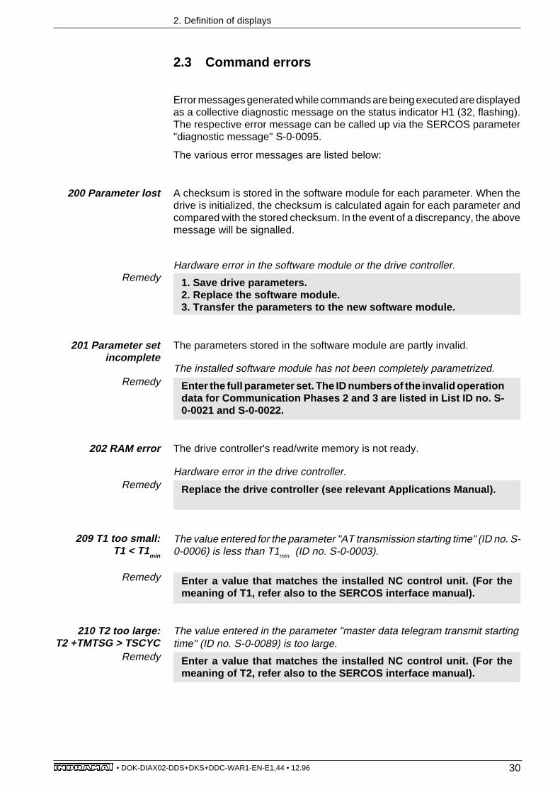
202 RAM error The drive controller's read/write memory is not ready.
Hardware error in the drive controller.
Replace the drive controller (see relevant Applications Manual).Remedy
209 T1 too small:T1 < T1
min
The value entered for the parameter "AT transmission starting time" (ID no. S-0-0006) is less than T1min (ID no. S-0-0003).
Enter a value that matches the installed NC control unit. (For themeaning of T1, refer also to the SERCOS interface manual).
Remedy
210 T2 too large:T2 +TMTSG > TSCYC
The value entered in the parameter "master data telegram transmit startingtime" (ID no. S-0-0089) is too large.
Enter a value that matches the installed NC control unit. (For themeaning of T2, refer also to the SERCOS interface manual).
Remedy
2.3 Command errors
2. Definition of displays
A checksum is stored in the software module for each parameter. When thedrive is initialized, the checksum is calculated again for each parameter andcompared with the stored checksum. In the event of a discrepancy, the abovemessage will be signalled.
Hardware error in the software module or the drive controller.
1. Save drive parameters.2. Replace the software module.3. Transfer the parameters to the new software module.
200 Parameter lost
Error messages generated while commands are being executed are displayedas a collective diagnostic message on the status indicator H1 (32, flashing).The respective error message can be called up via the SERCOS parameter"diagnostic message" S-0-0095.
The various error messages are listed below:
Remedy
The parameters stored in the software module are partly invalid.
The installed software module has not been completely parametrized.
Enter the full parameter set. The ID numbers of the invalid operationdata for Communication Phases 2 and 3 are listed in List ID no. S-0-0021 and S-0-0022.
201 Parameter setincomplete

31• DOK-DIAX02-DDS+DKS+DDC-WAR1-EN-E1,44 • 12.96
2. Definition of displays
Remedy
Remedy
Remedy
Remedy
Remedy
211 Master datatelegram too long
Remedy
The value entered in the parameter "length of master data telegram" (ID no.S-0-0010) is too long.
Enter a value that matches the installed NC control unit (refer also tothe SERCOS interface manual).
212 T1 too large:T1+ TATMT+ AT > T2
The value entered in the parameter "AT transmission starting time" (ID no. S-0-0006) is too large.
Enter a value that matches the installed NC control unit (refer also tothe SERCOS interface manual).
The value entered in the parameter "feedback acquisition starting time" (ID no.S-0-0007) is too large.
Enter a value that matches the installed NC control unit (refer also tothe SERCOS interface manual).
213 T4 too large:T4 + T4min > TSCYC
The value entered in the parameter "command valid time" (ID no. S-0-0008)is too large.
Enter a value that matches the installed NC control unit (refer also tothe SERCOS interface manual).
214 T3 too large:T3 > TSCYC
The value entered in the parameter "starting address in master data telegram"(ID no. S-0-0009) is too large.
Enter a value that matches the installed NC control unit (refer also tothe SERCOS interface manual).
215 Starting addressin MDT too large
Remedy
The value entered in the parameter "SERCOS cycle time" (ID no.S-0-0002)is invalid.
Only whole multiples of 1 ms are valid for the SERCOS cycle time.Enter a value that matches the installed NC control unit.
216 SERCOS cycletime incorrect
219 Starting addressin MDT incorrect
The contents of the parameter "starting address in master data telegram" (IDno. S-0-0009) are incorrect.
Consult the manufacturer of the NC control unit.
Remedy
243-244 Positioninitial error
The position of the motor encoder is calculated when the drive is initialized.If an error occurs during this calculation, this message will be generated.
Check that the motor feedback cable is correctly connected. If thereis no error in the feedack cable, replace the motor (see relevantdocumentation).

32• DOK-DIAX02-DDS+DKS+DDC-WAR1-EN-E1,44 • 12.96
2. Definition of displays
Remedy
250 No absoluteencoder available
260 Command error"travel to dead stop"
Remedy
270 RF missingduring drive-
generated movecommand
271 No referenceavailable
Remedy
Remedy
Status displaysunder the SERCOSinterface parameter
"diagnosticmessages" (ID.-Nr. S-
0-0095)
300 drive in torque mode
301 drive in velocity mode
302 position mode / encoder 1
303 position mode / encoder 1 / lagless
304 position mode / encoder 2
305 position mode / encoder 2 / lagless
320 Communications Phase 3 transition check
321 Communications Phase 4 transition check
322 set absolute measuring command (P-0-0012)
323 dead stop drive command
330 drive-generated homing command
On attempting to trigger the command "set absolute dimension", the drive hasdetected that the installed motor has no absolute encoder.
If necessary, install a motor with an absolute value encoder, otherwisesuppress the trigger for the command "set absolute dimension".
An error occurred while the command "travel to dead stop" was beingexecuted. This causes the drive to shut down.
Look up the error messages of the relevant drive.
The NC control unit has triggered a drive-generated move command (e.g.,drive-controlled homing cycle), without the drive having been activated priorto this.Software error in the NC control unit, since it must first activate the drive beforetriggering a drive-controlled move command.
Consult the manufacturer of the NC control unit.
The command "drive controlled homing cycle" has been sent to a motor withabsolute encoder without any marker having been set.
See the Applications Manual, "setting absolute dimensions in driveswith integral absolute encoders".

33• DOK-DIAX02-DDS+DKS+DDC-WAR1-EN-E1,44 • 12.96
3. List of INDRAMAT service representatives
3. List of INDRAMAT service representatives
ENGLAND
G.L. Rexroth Ltd.Indramat Division4 Esland Place, Love LaneCirencester, Glos GL 7 1 YGTel 02 85/65 86 71Telex 43 565Telefax 02 85/65 49 91
FRANCE
Rexroth - SigmaDivision IndramatParc des Barbanniers4, Place du VillageF - 92 632 Gennevilliers CedexTel 1/47 98 44 66Telex 616 581Telefax 1/47 94 69 41
ITALY
Rexroth S.p.A.Divisione IndramatVia G. Di Vittorio, 1I - 20 063 Cernusco S/N. MITel 02/9 23 65 - 270Telex 331 695Telefax 02/92 10 80 69
NETHERLANDS
Hydraudyne Hydrauliek B.V.Kruisbroeksestraat 1aP.O.Box 32NL - 5280 AA BoxtelTel 04 116/51 951Telefax 04 116/51 483
SPAIN
Rexroth S.A.Centro Industrial SantigaObradors s/nE-08130Santa Perpetuade Mogoda (Barcelona)Tel 03/7 18 68 51Telex 59 181Telefax 03/718 98 62
Goimendi S.A.División IndramatJolastokieta (Herrera)Apartado 11 37San Sebastian, 20 017Tel 043/40 01 63Telex 36 172Telefax 043/39 93 95
GERMANY
Lohr:
Indramat GmbHBgm.-Dr.-Nebel-Str. 297816 Lohr am MainTel 0 93 52/40-0Telex 6 89 421Telefax 0 93 52/40-4885
Chemnitz:
Indramat GmbHc/o Rexroth Vertriebs- undServicegesellschaft mbHBeckerstraße 3109120 ChemnitzTel 03 71/355-0Telefax 03 71/355-230
Düsseldorf:
Indramat GmbHTechnisches Büro RatingenHarkortstraße 25Postfach 32 0240880 Ratingen 1Tel 0 21 02/44 20 48 /-49Telefax 0 21 02/41 315
Stuttgart:
Indramat GmbHTechnisches BüroListstraße 1/271229 Leonberg 1Tel 0 71 52/25 076/-77Telefax 0 71 52/25 034
AUSTRIA
G.L. Rexroth GmbHGeschäftsbereich IndramatRandlstraße 14A - 4061 PaschingTel 07 229/44 01-72Telefax 07 229/44 01-80
DENMARK
BEC Elektronik ASZinkvej 6DK - 8900 RandersTel 086/44 78 66Telefax 086/44 71 60

34• DOK-DIAX02-DDS+DKS+DDC-WAR1-EN-E1,44 • 12.96
3. List of INDRAMAT service representatives
SWEDEN
AB Rexroth mecmanIndramat DivisionVaruvägen 7S - 125 81 StockholmTel 08/72 79 200Telefax 08/99 75 15
REPUBLIC OF SLOVENIA
ISKRA ElektromotorjiOtoki 21YU - 64 228 ZeleznikiTel 064/66 441Telex 34 578Telefax 064/ 67 150
CANADA
Basic Technologies CorporationBurlington Division3426 Mainway DriveBurlington, OntarioCanada L7M 1A8Tel 416/335 - 55 11Telex 06 18 396Telefax 416/335-41 84
MEXICO
Motorizacion y Diseño deControlesAv. Dr. Gustavo Baz No. 288Col. Parque Industrial la lomaApartado Postal No. 31854 060 TlalnepantlaEstado de MexicoTel 5/39 78 64 4Telefax 5/39 89 88 8
USA
Rexroth CorporationIndramat Division255 Mittel DriveWood Dale, Illinois 60 191Tel 708/8 60 - 10 10Telex 206 582Telefax 708/5 30 - 46 31
Rexroth CorporationIndramat Division2110 Austin AvenueRochester Hills, Michigan 48 309Tel 313/853 - 82 90Telefax 313/853 - 82 98
ARGENTINA
Mannesmann Rexroth S.A.I.CDivision IndramatAcassusso 48 41/71605 Munro (Buenos Aires)ArgentinaTel 01/7 56 01 40
01/7 56 02 40Telex 26 266 rexro arTelefax 01/7 56 01 36
BRAZIL
Rexroth Hidráulica Ltda.Divisão IndramatRua Heinrich Passold,130CP 156BR - 89. 107-000 Pomerode SCTel 04 73/87 03 21Telex 47 32 88 REXR BRTelefax 04 73/87 02 51
CHINA
G.L. Rexroth Ltd.Shanghai OfficeRoom 206Shanghai Intern. Trade Centre2200 Yan Xi LuShanghai 200335P.R. ChinaTel 2755-333Telefax 2755-666
INDIA
G. L. Rexroth Industries Ltd.Indramat DivisionPlot. 96, Phase IIIPeenya Industrial AreaBangalore - 56 00 58Tel 80/83 92 10 1
80/83 94 34 5
KOREA
Seo Chang Corporation Ltd.Room 903, Jeail Building44 - 35 Yeouido-DongYeongdeungpo-KuSeoul, KoreaTel 02/780 - 82 07 ~9Telefax 02/784 - 54 08
AUSTRALIA
Australasian Machine ToolCo. Pty. Ltd.9 Webber Parade,East Keilor (Melbourne)Victoria, 30 33, AustraliaTel 03/336 78 22Telefax 03/336 17 52
35• DOK-DIAX02-DDS+DKS+DDC-WAR1-EN-E1,44 • 12.96
4. Index
4. Index
Symbole+24 V error 22+8 V error 22±10 V error 22±15 V error 21
AAbsolute encoder error 23Absolute encoder not calibrated 26Address 0 set 29
BBleeder overtemperature shutdown 12Bleeder overtemperature warning 20Brake error 21Bridge fuse 20
CChecking and, if necessary, automatic clearing of 7Checking Hardware 8Clearing data RAM 7Command error 14Configuration error 26Cyclical operation 28
DData RAM error 24DLC watchdog error, no communication with DLC poss 26Double MDT error 29Double MST error 29Double MST error shutdown 10Drive data invalid 24Drive enable signal 9Drive halt 9Drive overtemperature shutdown 12Drive overtemperature warning 19Drive ready 9
EE-STOP 9EPROM checksum error 27Erroneous internal hardware synchronization 21Error during phase progression 11, 27Error during phase regression 27Error in detecting the marker of the external enco 18Error in internal software synchronization 15Error reading drive data 24Error reading motor data 25Error while writing motor data 25Error while writing to parameter memory 25Excessive actual position difference 16Excessive deviation 14Excessive position command difference 16

36• DOK-DIAX02-DDS+DKS+DDC-WAR1-EN-E1,44 • 12.96
4. Index
External encoder failure: frequency limit exceeded 18External encoder failure: quadrant error 17External encoder failure: signals too small 17External power supply error 15
HH1 status indicator 5H2 status indicator 6Hardware error 28
IInitializing hardware 8Initializing software 8Initializing the SERCOS 8Invalid communication phase shutdown 11Invalid communications phase 27Invalid feedback data --> Phase 2 17Invalid parameters for Phase 3 28Invalid parameters for Phase 4 28Invalid reference cam position 15
LLoading program 7Low absolute encoder battery voltage 18
MMaster encoder failure 19Motor data invalid 25Motor encoder failure 13Motor overtemperature shutdown 12Motor overtemperature warning 20MST not yet received 29
NNC control unit has not yet triggered progression 28No progression to Phase 1 27Number of transmitted pattern data invalid 23
OOutput power 27Overcurrent 13Overcurrent: short to ground 20Overvoltage error 13
PParameter data invalid 25Park axis command 9Pattern data transmission time invalid 22Phase 0 9Phase 1 9Phase 2 10Phase 3 10Phase progression without ready signal 11Power supply to driver stage 22Program RAM error 24

37• DOK-DIAX02-DDS+DKS+DDC-WAR1-EN-E1,44 • 12.96
4. Index
RReady for input power 9
SStarting lock-out 9Switching to uninitialized operating mode 11
TTest mode 29Travel limit switch detected 17Travel limit switch is exceeded 14
UUndervoltage error 13
VVelocity loop error 24
WWatchdog 8

Indramat


