20
Deaeration of heating and cooling systems Theoretical foundations and practical solutions
| Date post: | 08-May-2018 |
| Category: |
Documents |
| Upload: | trinhtuong |
| View: | 218 times |
| Download: | 2 times |
Deaeration of heating and cooling systemsTheoretical foundations and
practical solutions
2
Dear business partner,
everybody knows them, the so-called “air problems” - cold radiators, circulation disorders, flow noise, accumulation of mud, corrosion ... - and no solution in sight.
Therefore, we have in form of a research co-operation with the Technical University of Dresden, Institute for Power Engineering, dealt with the issue “Deaeration of fluid systems” since 1995.
Already in 1997, we prepared a first intermediate report with the publi-cation of “Gase in Waterheizungsanlagen Teil 1” /1/ (Gases in water heating systems part 1). In essence, this report theoretically covered the topic “Air in water heating systems”.
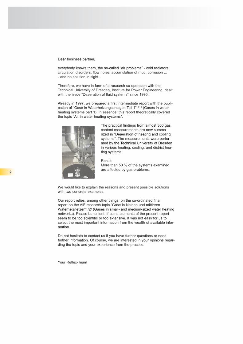
The practical findings from almost 300 gas content measurements are now summa-rized in “Deaeration of heating and cooling systems”. The measurements were perfor-med by the Technical University of Dresden in various heating, cooling, and district hea-ting systems.
Result:More than 50 % of the systems examined are affected by gas problems.
We would like to explain the reasons and present possible solutions with two concrete examples.
Our report relies, among other things, on the co-ordinated final report on the AiF research topic “Gase in kleinen und mittleren Waterheiznetzen” /2/ (Gases in small- and medium-sized water heating networks). Please be lenient, if some elements of the present report seem to be too scientific or too extensive. It was not easy for us to select the most important information from the wealth of available infor-mation.
Do not hesitate to contact us if you have further questions or need further information. Of course, we are interested in your opinions regar-ding the topic and your experience from the practice.
Your Reflex-Team
3
1. Gas is not equal to air - on the 4 - 5complexity of the topic
How gases get into closed systems Gases are dissolved in the filling and make-up water. 6 During the refilling and partial filling after repairs 6 residual air is occluded. Air can diffuse into the system through components. 6 - 7 Due to chemical reactions and corrosion 7 - 8 gases may build up. In case of an improper execution of the pressure maintenance 8 - 10 air may penetrate into the system. The gas problem was aggravated with the evolution 11 of the installation technology.
Technical possibilities for the physical 12deaeration Deaeration at system pressure 12 - 13 Deaeration at atmospheric pressure 13 Deaeration in the vacuum 14 Comparison of different deaeration systems 15 Deaeration effectiveness only in theory 15 - 16 - misinterpretation of Henry´s law
Problem solution with two examples 17
Reflex pressure-maintaining and deaeration systems 18
Compendium of the chapters 19
1.
2.2.
3.3.
4.4.5.5.6.6.
Bibliography
/1/ Gase in Waterheizungsanlagen part 1, July 1997
/2/ TU Dresden, Institute for Power Engineering: “Gase in kleinen und mittleren Wasserheiznetzen“, co-ordinated final report, AiF research topic no. 11103 B, November 1998
/3/ VDI 2035 Bl. 2: Vermeidung von Schäden in Warmwasserheizungs- anlagen, wasserseitige Korrosion, Beuth Verlag GmbH, Sept. 1998
/4/ DIN 4726: Rohrleitungen aus Kunststoff für Warmwasser-Fußboden- heizungen, Allgemeine Anforderungen
/5/ Rühling, Preußer: Gase in Warmwasser-Heizungssystemen, unpublished research report, Technical University of Dresden, Institute for Power Engineering, Chair for Energy Management, 25.07.1996
/6/ DIN 4807 T 2: Ausdehnungsgefäße, offene und geschlossene Aus- dehnungsgefäße für wärmetechnische Anlagen, Ausführung, An- forderungen und Prüfung, May 1999
/7/ AGFW-Seminar “Wassertechnologie der Fernwärmeversorgung” (Water technology of the district heating supply), September 1998, Rostock/Warnemünde Dr. Kruse: Korrosion und Korrosionsschutz
/8/ AGFW-Seminar “Wassertechnologie der Fernwärmeversorgung” (Water technology of the district heating supply), September 1998, Rostock/Warnemünde Hopp: Fernwärmenetze mit unterschiedlicher Wasserqualität
Table of contents
4
Gas is not equal to air - on the complexity of the topic
In the practice, the discussion is often simplified and shortened as people, for example, speak of “air” problems as such and tend to incorrectly treat air as equivalent to gas. Thus, “air problems” are lowered to the level of “oxy-gen problems”, and each “air problem” is build up into a corrosion problem. Unfortunately, it is not that easy!
Practically, the gas problem shows itself in two forms:
Some gases can, in free or dissolved form, cause corrosion of the most different materials.
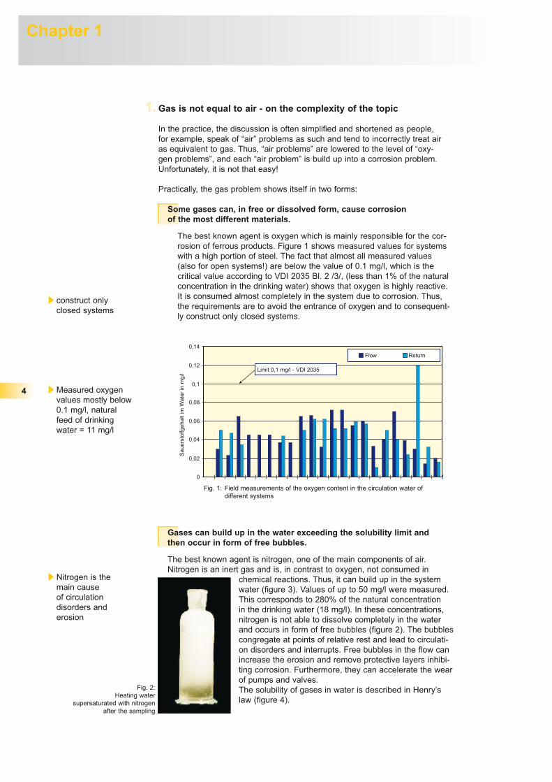
The best known agent is oxygen which is mainly responsible for the cor-rosion of ferrous products. Figure 1 shows measured values for systems with a high portion of steel. The fact that almost all measured values (also for open systems!) are below the value of 0.1 mg/l, which is the critical value according to VDI 2035 Bl. 2 /3/, (less than 1% of the natural concentration in the drinking water) shows that oxygen is highly reactive. It is consumed almost completely in the system due to corrosion. Thus, the requirements are to avoid the entrance of oxygen and to consequent-ly construct only closed systems.
Gases can build up in the water exceeding the solubility limit and then occur in form of free bubbles.
The best known agent is nitrogen, one of the main components of air. Nitrogen is an inert gas and is, in contrast to oxygen, not consumed in
chemical reactions. Thus, it can build up in the system water (figure 3). Values of up to 50 mg/l were measured. This corresponds to 280% of the natural concentration in the drinking water (18 mg/l). In these concentrations, nitrogen is not able to dissolve completely in the water and occurs in form of free bubbles (figure 2). The bubbles congregate at points of relative rest and lead to circulati-on disorders and interrupts. Free bubbles in the flow can increase the erosion and remove protective layers inhibi-ting corrosion. Furthermore, they can accelerate the wear of pumps and valves.The solubility of gases in water is described in Henry’s law (figure 4).
Flow Return
Limit 0,1 mg/l - VDI 2035
Fig. 1: Field measurements of the oxygen content in the circulation water of different systems
Sau
erst
offg
ehal
t im
Wat
er in
mg/
l
Fig. 2:Heating water
supersaturated with nitrogenafter the sampling
Nitrogen is themain causeof circulation disorders anderosion
Measured oxygen values mostly below 0.1 mg/l, natural feed of drinking water = 11 mg/l
construct onlyclosed systems
1.1.
Chapter 1
5
FloReturnHP-value air saturation - N2 1)
HP-value saturation 100 % N2 2)
open EV Compressor-controlledPM, vessel without
diaphragm
Compressor-controlled PM,DW make-up,
diaphragm vessel
Pump-controlled PM,DW make-up,
diaphragm vessel
Compressor-controlled PM, primary water
make-up, diaphragm vessel
Pump-controlled PM,primary water
make-up,diaphragm vessel
Problematic systems Problematic systems
Nitr
ogen
con
tent
in th
e w
ater
in m
g/l
with direct contact water « air(79 vol % N2)with direct contact water « 100 % N2
Nitrogen contentdrinking water
critical concentrationat 70°C and 0.5 bar
Saturation value (red bar)< actual value (green bar)
1)
2)
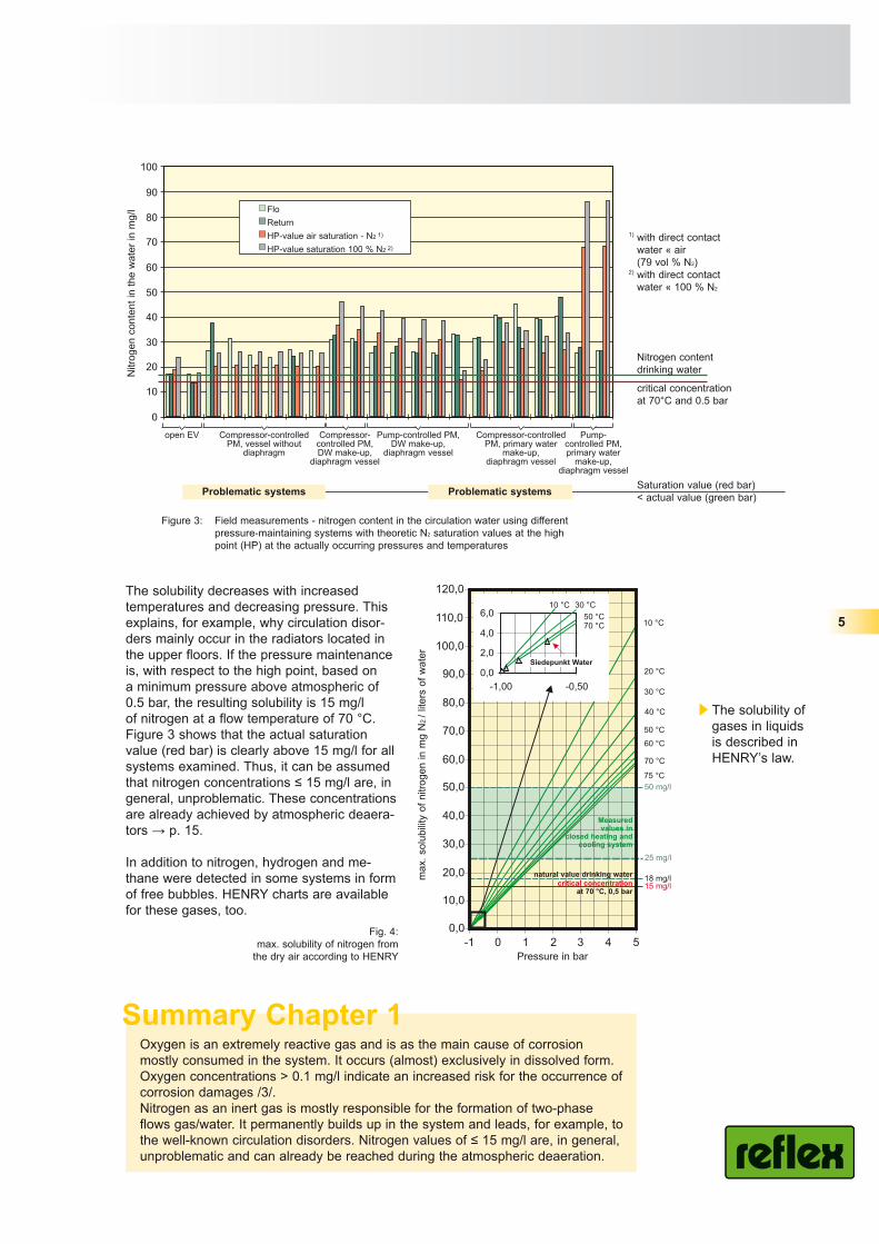
Figure 3: Field measurements - nitrogen content in the circulation water using different pressure-maintaining systems with theoretic N2 saturation values at the high point (HP) at the actually occurring pressures and temperatures
The solubility decreases with increased temperatures and decreasing pressure. This explains, for example, why circulation disor-ders mainly occur in the radiators located in the upper floors. If the pressure maintenance is, with respect to the high point, based on a minimum pressure above atmospheric of 0.5 bar, the resulting solubility is 15 mg/l of nitrogen at a flow temperature of 70 °C. Figure 3 shows that the actual saturation value (red bar) is clearly above 15 mg/l for all systems examined. Thus, it can be assumed that nitrogen concentrations ≤ 15 mg/l are, in general, unproblematic. These concentrations are already achieved by atmospheric deaera-tors → p. 15.
In addition to nitrogen, hydrogen and me-thane were detected in some systems in form of free bubbles. HENRY charts are available for these gases, too.
max
. sol
ubili
ty o
f nitr
ogen
in m
g N
2 / l
iters
of w
ater
Pressure in bar
Fig. 4:max. solubility of nitrogen from
the dry air according to HENRY
The solubility of gases in liquids is described in HENRY’s law.
Oxygen is an extremely reactive gas and is as the main cause of corrosion mostly consumed in the system. It occurs (almost) exclusively in dissolved form. Oxygen concentrations > 0.1 mg/l indicate an increased risk for the occurrence of corrosion damages /3/.Nitrogen as an inert gas is mostly responsible for the formation of two-phase flows gas/water. It permanently builds up in the system and leads, for example, to the well-known circulation disorders. Nitrogen values of ≤ 15 mg/l are, in general, unproblematic and can already be reached during the atmospheric deaeration.
Summary Chapter 1
Siedepunkt Water
Measured values in
closed heating and cooling system
natural value drinking watercritical concentration
at 70 °C, 0,5 bar
6
How gases get into closed systems
Gases are dissolved in the filling and make-up water.
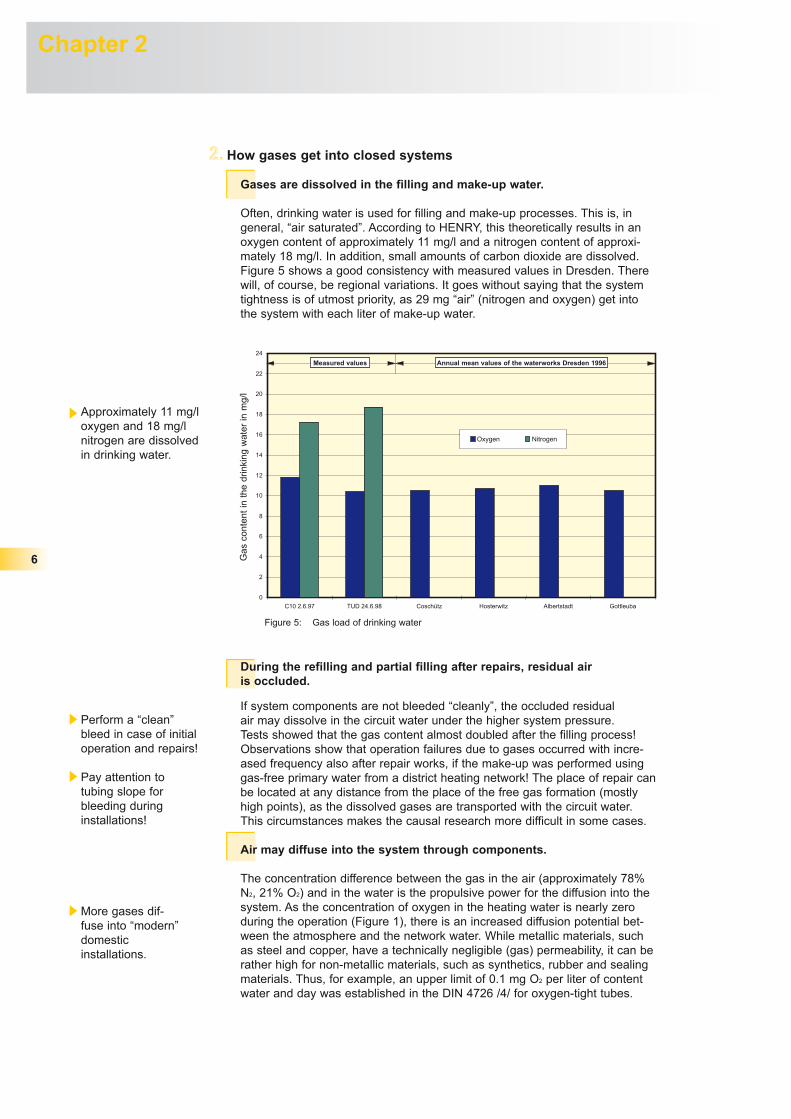
Often, drinking water is used for filling and make-up processes. This is, in general, “air saturated”. According to HENRY, this theoretically results in an oxygen content of approximately 11 mg/l and a nitrogen content of approxi-mately 18 mg/l. In addition, small amounts of carbon dioxide are dissolved. Figure 5 shows a good consistency with measured values in Dresden. There will, of course, be regional variations. It goes without saying that the system tightness is of utmost priority, as 29 mg “air” (nitrogen and oxygen) get into the system with each liter of make-up water.
During the refilling and partial filling after repairs, residual airis occluded.
If system components are not bleeded “cleanly”, the occluded residual air may dissolve in the circuit water under the higher system pressure. Tests showed that the gas content almost doubled after the filling process! Observations show that operation failures due to gases occurred with incre-ased frequency also after repair works, if the make-up was performed using gas-free primary water from a district heating network! The place of repair can be located at any distance from the place of the free gas formation (mostly high points), as the dissolved gases are transported with the circuit water. This circumstances makes the causal research more difficult in some cases.
Air may diffuse into the system through components.
The concentration difference between the gas in the air (approximately 78% N2, 21% O2) and in the water is the propulsive power for the diffusion into the system. As the concentration of oxygen in the heating water is nearly zero during the operation (Figure 1), there is an increased diffusion potential bet-ween the atmosphere and the network water. While metallic materials, such as steel and copper, have a technically negligible (gas) permeability, it can be rather high for non-metallic materials, such as synthetics, rubber and sealing materials. Thus, for example, an upper limit of 0.1 mg O2 per liter of content water and day was established in the DIN 4726 /4/ for oxygen-tight tubes.
Approximately 11 mg/l oxygen and 18 mg/l nitrogen are dissolved in drinking water.
Perform a “clean” bleed in case of initial operation and repairs!
Pay attention to tubing slope for bleeding during installations!
More gases dif-fuse into “modern” domestic installations.
2.2.
Figure 5: Gas load of drinking water
Gas
con
tent
in th
e dr
inki
ng w
ater
in m
g/l
Measured values Annual mean values of the waterworks Dresden 1996
Oxygen Nitrogen
Chapter 2

7
Gases may form due to chemical reactions and corrosion.
Gases may build up in the content water under various boundary conditions, such as material combinations, water quality, chemical additives, ingredients, pressure, and temperature. In addition to the above mentioned nitrogen (from the air), hydrogen and methane were detected in some systems during the field tests. Not all the mechanisms for the formation of gases from chemical reac-tions are fully clarified, some things are still based on assumptions only. There is a need for action in this area, too.
Hydrogen H2 can build up in systems with ferrous materials according to the so-called “Schikorr” reaction and can accumulate up to oversaturation. The proportioning of sodium sulphite Na2SO3 may lead to the formation of hydro-gen sulphide H2S /7/. Hydrogen sulphide can also build up through so-called sulphate-reducing bacteria /8/. The resulting H2S can, in systems with copper materials (e.g. pipe bundles of heat exchangers, copper-soldered plate heat exchangers), be transformed into copper sulphide Cu2S through a reaction with copper oxide Cu2O. In contrast to Cu2O, Cu2S does not build up a protective coating. The result are corrosion signs and corrosion damages which often occur after few years of operation.
Another assumption is that hydrogen builds up due to biological processes taking place during the degradation of fats. These are used for the manufacturing of certain tube systems.
Figure 6 shows a rating of the diffusing O2 quantity for different heating systems. Thus, the amount of oxygen diffusing into the system is 3 to 5 powers of ten high-er for plastic floor heatings than for the classical installation using copper or steel tubes. Especially with respect to floor heatings in a mixed installation with steel tubes, this can already lead to corrosion damages.
Figure 6: Rating of diffusing gas quantities in dependence on the thermal performance of the system
Diff
usin
g O
2 qua
ntity
in m
g/da
y
Nominal thermal output of the system in KW
average system volume in litres
Be careful with respect to the proportioning of sodium sulphite in systems with copper materials.
Plastic tubes 0,1 mg/(l . d)
Plastic tubes 0,001 mg/(l . d)
Installations with cast iron radiators or flat radiatorsConventional installation
with steel or copper tubes
with cast iron radiators/flat radiators
with floor heating
Floor heating
Floor heating
max. O2 content of 1 litre of water at 1 bar (abs) and 10 °C
8
The use of aluminium (e.g. aluminium radiators) can turn out to be critical. These must be equipped with a sufficient protective layer already during the manufactu-ring, as the natural protective layers are only stable up to a pH value of 8.5, but ferriferrous systems should be operated with a pH value > 8.5. In a system with aluminium radiators, clear signs for corrosion were detected with 3.2 mg/l nitro-gen. This load leads to the formation of free hydrogen bubbles at a temperature of 30 °C and a pressure of 1 bar(Ü).
The formation of methane gas CH4 is, in general, attributed to bacteria and fermentation gases.
In case of improper execution and maintenance of the pressure-maintaining system, air may penetrate into the system.
An insufficient pressure maintenance is still the most common reason for “gas problems”, in particular in small systems with diaphragm expansion vessels. Therefore, we would like to mention the most important principles for a properly working pressure maintenance.
A pressure-maintaining system must ensure that low pressure, steam for-mation, cavitation, or eliminations of gas do not occur at any point of the network at rest (circulation pumps off) and circulation operation. Particular attention must be paid to system high points, pumps, and control valves.
The most common defects:
incorrect initial operation, missing maintenanceIn particular with respect to diaphragm expansion vessels, the gas admission pressures p0 and the water filling pressures pF are not adjusted to the system conditions. The annual maintenance with admission pressure control according to DIN 4807 T 2 /6/ is performed extremely rarely. In the most cases, even the required protected cut-offs are not available.
Internal tests showed the following results:The admission pressures p0 are often too high, and the filling pressures pF (hydraulic back pressure) are often too low.
We already take these findings into consideration for the calculation in our EDP calculation program for the dimensioning of diaphragm pressure expansion vessels by taking into account a minimum filling pressure pF of 0.3 bar above the admission pressure.
Be careful with respect to mixed installations with alu-minium
Corrosion +free H2 bubbles
Chapter 2
9
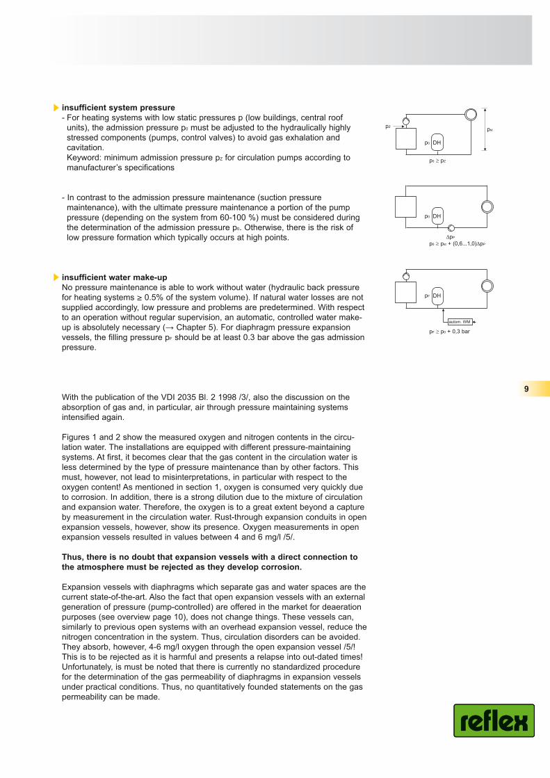
insufficient system pressure- For heating systems with low static pressures p (low buildings, central roof units), the admission pressure p0 must be adjusted to the hydraulically highly stressed components (pumps, control valves) to avoid gas exhalation and cavitation. Keyword: minimum admission pressure pZ for circulation pumps according to manufacturer’s specifications
- In contrast to the admission pressure maintenance (suction pressure maintenance), with the ultimate pressure maintenance a portion of the pump pressure (depending on the system from 60-100 %) must be considered during the determination of the admission pressure p0. Otherwise, there is the risk of low pressure formation which typically occurs at high points.
insufficient water make-upNo pressure maintenance is able to work without water (hydraulic back pressure for heating systems ≥ 0.5% of the system volume). If natural water losses are not supplied accordingly, low pressure and problems are predetermined. With respect to an operation without regular supervision, an automatic, controlled water make-up is absolutely necessary (→ Chapter 5). For diaphragm pressure expansion vessels, the filling pressure pF should be at least 0.3 bar above the gas admission pressure.
With the publication of the VDI 2035 Bl. 2 1998 /3/, also the discussion on the absorption of gas and, in particular, air through pressure maintaining systems intensified again.
Figures 1 and 2 show the measured oxygen and nitrogen contents in the circu-lation water. The installations are equipped with different pressure-maintaining systems. At first, it becomes clear that the gas content in the circulation water is less determined by the type of pressure maintenance than by other factors. This must, however, not lead to misinterpretations, in particular with respect to the oxygen content! As mentioned in section 1, oxygen is consumed very quickly due to corrosion. In addition, there is a strong dilution due to the mixture of circulation and expansion water. Therefore, the oxygen is to a great extent beyond a capture by measurement in the circulation water. Rust-through expansion conduits in open expansion vessels, however, show its presence. Oxygen measurements in open expansion vessels resulted in values between 4 and 6 mg/l /5/.
Thus, there is no doubt that expansion vessels with a direct connection to the atmosphere must be rejected as they develop corrosion.
Expansion vessels with diaphragms which separate gas and water spaces are the current state-of-the-art. Also the fact that open expansion vessels with an external generation of pressure (pump-controlled) are offered in the market for deaeration purposes (see overview page 10), does not change things. These vessels can, similarly to previous open systems with an overhead expansion vessel, reduce the nitrogen concentration in the system. Thus, circulation disorders can be avoided. They absorb, however, 4-6 mg/l oxygen through the open expansion vessel /5/! This is to be rejected as it is harmful and presents a relapse into out-dated times! Unfortunately, is must be noted that there is currently no standardized procedure for the determination of the gas permeability of diaphragms in expansion vessels under practical conditions. Thus, no quantitatively founded statements on the gas permeability can be made.
pZ
p0
pst
p0 pZ
DH
p0
pP
p0 pst + (0,6...1,0)pP
DH
pF
pF p0 + 0,3 bar
DH
autom. WM
10
nicht Stand der Technik
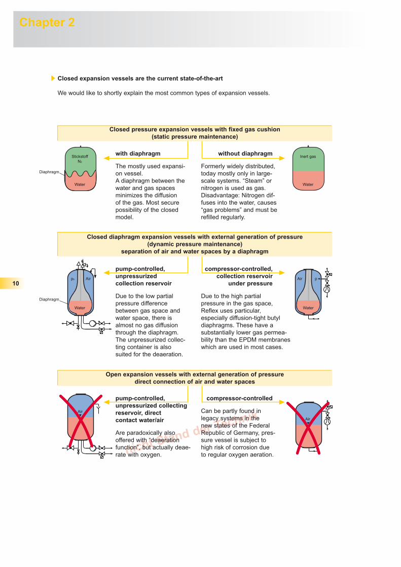
Closed expansion vessels are the current state-of-the-art
We would like to shortly explain the most common types of expansion vessels.
Closed pressure expansion vessels with fixed gas cushion(static pressure maintenance)
with diaphragm
The mostly used expansi-on vessel. A diaphragm between the water and gas spaces minimizes the diffusion of the gas. Most secure possibility of the closed model.
without diaphragm
Formerly widely distributed, today mostly only in large-scale systems. “Steam” or nitrogen is used as gas. Disadvantage: Nitrogen dif-fuses into the water, causes “gas problems” and must be refilled regularly.
StickstoffN2
Water
Inert gas
Water
Diaphragm
pump-controlled,unpressurizedcollection reservoir
Due to the low partial pressure difference between gas space and water space, there is almost no gas diffusion through the diaphragm. The unpressurized collec-ting container is also suited for the deaeration.
compressor-controlled, collection reservoir under pressure
Due to the high partialpressure in the gas space, Reflex uses particular, especially diffusion-tight butyl diaphragms. These have a substantially lower gas permea-bility than the EPDM membraneswhich are used in most cases.
Airpb
Water
Air p
Water
Diaphragm
Closed diaphragm expansion vessels with external generation of pressure(dynamic pressure maintenance)
separation of air and water spaces by a diaphragm
pump-controlled,unpressurized collectingreservoir, direct contact water/air
Are paradoxically also offered with “deaerationfunction”, but actually deae-rate with oxygen.
compressor-controlled
Can be partly found in legacy systems in the new states of the Federal Republic of Germany, pres-sure vessel is subject to high risk of corrosion due to regular oxygen aeration.
Air
Air
Open expansion vessels with external generation of pressuredirect connection of air and water spaces
Chapter 2
11
The gas problem was aggravated with the development of the installation technology.
While heating installations often used to be build with steel tubes and an over-head distribution with centralized bleeding containing a “modest” number of pumps and fittings, the current situation is completely different:
Bottom and horizontal distribution systems imply may decentralized air bleeds which are sometimes difficult to access.
Horizontal radiant heating systems and cooling blankets as well as extensive horizontal distribution systems are difficult to bleed using traditional methods.
Due to the use of components, such as synthetics and rubber, as well as the increased number of sealing surfaces in the installation, more “air” diffused into the systems. → P. 6/7
Mixed installations with various metallic materials cause a formation of gases under certain conditions. → P. 7, 8
The current situation is as follows: on the one hand, the gas load of the newer systems is higher. On the other, conventional “bleedings” at many decentralized air bleeds are demanded too much and cannot resolve the problems.
The pressure maintenance plays a central role with respect to the gas problem. It must be closed towards the atmosphere in order to avoid, above all, the absorption of oxygen. Furthermore, it must safely avoid low pressure and cavitation. Many diaphragm pressure expansion vessels, especially in small installations, are improperly configured with respect to gas and water and are not maintained according to DIN 4807 T 2 /6/. In this area, there is still need for information and action.The penetration and formation of gases is almost inevitable for closed systems (filling, make-up, diffusion, chemical reactions).Gases must be purposefully dissipated from closed systems through appropriate devices to avoid circulation disorders, erosion, and corro-sion. Thereby, a centralized solution is to be preferred. The deaeration must be a one-way street: Gases must be able to exhaust, but air must not be allowed to get in!
Summary Chapter 2
12
3.3. Technical possibilities for the physical deaeration
The possibilities of deaeration are as diverse as the results.
The most costly, but certainly also the most effective method is the thermal deae-ration with steam which is, for example, realized in power stations. In the present document, however, we would like to cover only technically feasible, physical methods which can also be realized in a temperature range < 100°C and in the building technology.
Unfortunately, there is no standardized procedure for the evaluation of deaeration systems. This opens the way to statements which are effective to advertising pur-poses, but have no foundation and even are incorrect.
You can, for example, read about air separators which get all the air out of the system. Is “air” intended to include oxygen and nitrogen? Does “all the air” also mean dissolved air?
An advertising leaflet of a manufacturer of pressure-maintaining systems with a built-in atmospheric relief into an open expansion vessel contains the following statement:
Quotation: “New competitors point out that ... oxygen may get from the open expansion vessel into the system water. This is only partially true, but insignificant, because unpressurized water can only absorb small amounts of oxygen.”
The last sentence contains three false statements:1. it is true that oxygen gets into the system water. 2. This is not insignificant because3. unpressurized water is perfectly able to absorb large amounts of oxygen - approximately 11 mg/ l at 10 °C, and still more than 5 mg/l at 70 °C. This is 50 times higher than the recommendation of 0.1 mg/l according to VDI 2035!
Therefore, we would like to describe the effectiveness of some common physical procedures which are realized in the building and plant engineering. These are mainly influenced by three factors:- temperature of the medium- pressure of the medium- principle of action
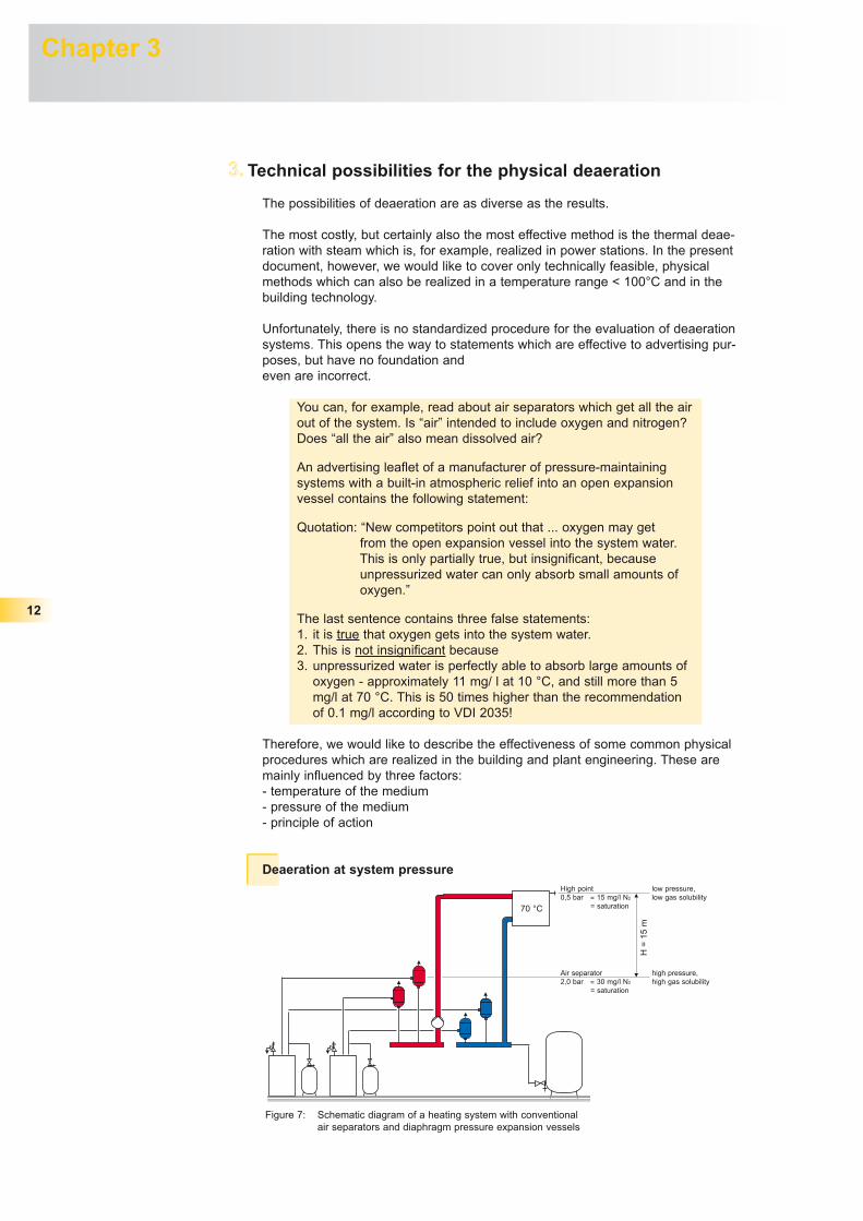
Deaeration at system pressure
70 °C
High point0,5 bar 15 mg/l N2
= saturation
low pressure,low gas solubility
Air separator2,0 bar 30 mg/l N2
= saturation
high pressure,high gas solubility
H =
15
m
Figure 7: Schematic diagram of a heating system with conventional air separators and diaphragm pressure expansion vessels
Chapter 3
13
In many heating and cooling circuits, only so-called mechanical air separators are deployed for the deaeration. These can only separate free gases, but no dis-solved gases. There are multiple principles of action. They all have in common that they are under the pressure of the system (high gas solubility), and that the effectiveness is substantially influenced by the place of installation (high point, low point, flow, return, distance to vessel and pump).
“Air problems” can only be reliably avoided if the installation is performed directly at the system high points. As today systems are typically planned with a bottom distribution, the installation is performed at less favorable, low points. Then, the effectiveness is substantially impaired, if not even uncertain. For example, the nitrogen content in Figure 7 could only be reduced to approximately 30 mg/l. In order to reliably avoid eliminations of gas at the high point, 15 mg/l would be required. Mechanical air separators are not able to influence the content of dissol-ved gases or the corrosion processes.
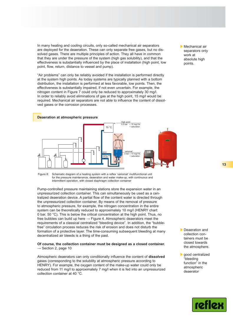
Deaeration at atmospheric pressure
Pump-controlled pressure maintaining stations store the expansion water in an unpressurized collection container. This can simultaneously be used as a cen-tralized deaeration device. A partial flow of the content water is directed through the unpressurized collection container. By means of the removal of pressure to atmospheric pressure, for example, the nitrogen concentration in the entire system can be theoretically reduced to approximately 10 mg/l (HENRY chart: 0 bar, 50 °C). This is below the critical concentration at the high point. Thus, no free bubbles can build up here → Figure 4. Atmospheric deaerators meet the requirements of a classical centralized “bleeding device”. In addition, the “bubble-free” circulation process reduces the risk of erosion and does not disturb the formation of a protective layer. The time-consuming subsequent bleeding at many decentralized air bleeds is a thing of the past.
Of course, the collection container must be designed as a closed container. → Section 2, page 10
Atmospheric deaerators can only conditionally influence the content of dissolved gases (corresponding to the solubility at atmospheric pressure according to HENRY). For example, the oxygen content of the make-up water could only be reduced from 11 mg/l to approximately 7 mg/l when it is fed into an unpressurized collection container at 40 °C.
70 °C
50 °C
High point0,5 bar 15 mg/l N2
= saturation
’variomat’0 bar 10 mg/l N2
= saturation
Figure 8: Schematic diagram of a heating system with a reflex ‘variomat’ multifunctional unit for the pressure maintenance, deaeration and water make-up, with continuous and intermittent operation, with closed diaphragm collection container
gassy
Partial flowlow-gas
Deaeration and collection con-tainers must be closed towards the atmosphere.
good centralized “bleedingfunction” in the atmospheric deaerator
Mechanical air separators only work at absolute high points.

14
Deaeration in the vacuum
Vacuum deaerators deaerate a partial flow of the network content water in the vacuum. The solubility of gases in the vacuum is actually zero. Nevertheless, the deaeration in the static vacuum is rather slow (→ Figure 10). Only a dynamization, e.g. by spraying the water in the vacuum (→ Figure 11), ensures a high deaeration efficiency.
Dynamic vacuum deaerators are highly effective because the formation of free gas bubbles is reduced and the content of dissolved gases is substantially reduced, completely independent from the pressure conditions in the network. Thus, reactive gases (e.g. H2, O2) can be removed, and the corrosion can be minimized. A substantial advantage of the vacuum deaeration in comparison with chemical methods is the uncompromising elimination of all gases, including inert gases, which evade a chemical bond! Measurements showed that, for example, the nitrogen content in the circulation water can be reduced to approximately 3 mg/l using a ’servitec’ vacuum spray tube deaeration. This approximately corresponds to the values which have been measured for thermal deaerators. The partial flow deaeration of classical steel tube system has only a conditional influence on the oxygen content of the network content water. If the partial flow amounts are too small, the oxygen partially evades from a central elimination due to its quick reactivity. This is a problem of all partial flow deaerations!
The deaeration of the make-up and filling water, however, is very effective. The oxygen content can be reduced by approximately 80%.
The deaerationperformance in the static vacuum is too low.
Vacuum deaera-tors can separate reactive and inert gases.
70 °C
50 °C
High point0,5 bar 15 mg/l N2
= saturation
’servitec’-0,9 bar 0 mg/l N2
= saturation
Figure 9: Schematic diagram of a heating system with a reflex ’servitec’ dynamic vacuum spray tube deaeration for the deaeration of the network and make-up water
Figure 10:static vacuumdeaeration in the”static vacuum”
Partial flowgassy
Partial flowlow-gas
Figure 11:dynamicvacuum deaerationat the ’servitec’test stand
Chapter 3
’servitec 35’
15
Comparison of different deaeration systems
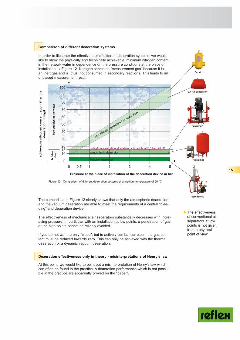
In order to illustrate the effectiveness of different deaeration systems, we would like to show the physically and technically achievable, minimum nitrogen content in the network water in dependence on the pressure conditions at the place of installation → Figure 12. Nitrogen serves as “measurement gas” because it is an inert gas and is, thus, not consumed in secondary reactions. This leads to an unbiased measurement result.
The comparison in Figure 12 clearly shows that only the atmospheric deaeration and the vacuum deaeration are able to meet the requirements of a central “blee-ding” and deaeration device.
The effectiveness of mechanical air separators substantially decreases with incre-asing pressure. In particular with an installation at low points, a penetration of gas at the high points cannot be reliably avoided.
If you do not want to only “bleed”, but to actively combat corrosion, the gas con-tent must be reduced towards zero. This can only be achieved with the thermal deaeration or a dynamic vacuum deaeration.
Deaeration effectiveness only in theory - misinterpretations of Henry’s law
At this point, we would like to point out a misinterpretation of Henry’s law which can often be found in the practice. A deaeration performance which is not possi-ble in the practice are apparently proved on the “paper”.
achi
evab
le n
itrog
en c
once
ntra
tion
afte
r th
ede
aera
tion
in m
g/l
bubb
le-fr
eefr
ee b
ubbl
es in
the
wat
er
Pressure at the place of installation of the deaeration device in bar
critical concentration at system high points at 0,5 bar, 70 °Catmospheric deaerator
Microbubble separators / Air s
eparators
Vacuum deaerator
Figure 12: Comparison of different deaeration systems at a medium temperature of 50 °C
The effectiveness of conventional air separators at low points is not given from a physical point of view.
’LA Air separator’
’exair’
’variomat’
’gigamat’
’servitec 60’
16
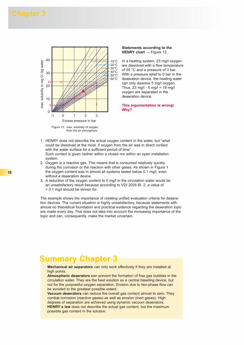
1. HENRY does not describe the actual oxygen content in the water, but “what could be dissolved at the most, if oxygen from the air was in direct contact with the water surface for a sufficient period of time”. Such contact is given neither within a closed nor within an open installation system.2. Oxygen is a reactive gas. This means that is consumed relatively quickly during the corrosion or the reaction with other gases. As shown in Figure 1 the oxygen content was in almost all systems tested below 0.1 mg/l, even without a deaeration device.3. A reduction of the oxygen content to 5 mg/l in the circulation water would be an unsatisfactory result because according to VDI 2035 Bl. 2, a value of < 0.1 mg/l should be striven for.
The example shows the importance of creating unified evaluation criteria for deaera-tion devices. The current situation is highly unsatisfactory, because statements with almost no theoretical foundation and practical evidence regarding the deaeration topic are made every day. This does not take into account the increasing importance of the topic and can, consequently, make the market uncertain.
Mechanical air separators can only work effectively if they are installed at high points.Atmospheric deaerators can prevent the formation of free gas bubbles in the circulation water. They are the best solution as a central bleeding device, but not for the purposeful oxygen separation. Erosion due to two-phase flow can be avoided to the greatest possible extent.Vacuum deaerators can reduce the overall gas content almost to zero. They combat corrosion (reactive gases) as well as erosion (inert gases). High degrees of separation are achieved using dynamic vacuum deaerators.HENRY´s law does not describe the actual gas content, but the maximum possible gas content in the solution.
Summary Chapter 3
Statements according to the HENRY chart → Figure 13
In a heating system, 23 mg/l oxygen are dissolved with a flow temperature of 55 °C and a pressure of 3 bar. With a pressure relief to 0 bar in the deaeration device, the heating water can only dissolve 5 mg/l oxygen. Thus, 23 mg/l - 5 mg/l = 18 mg/l oxygen are separated in the deaeration device.
This argumentation is wrong!Why?m
ax. s
olub
ility
in m
g O
2 /kg
wat
er
Excess pressure in bar
Figure 13: max. solubility of oxygen from the air atmosphere
Chapter 3
17
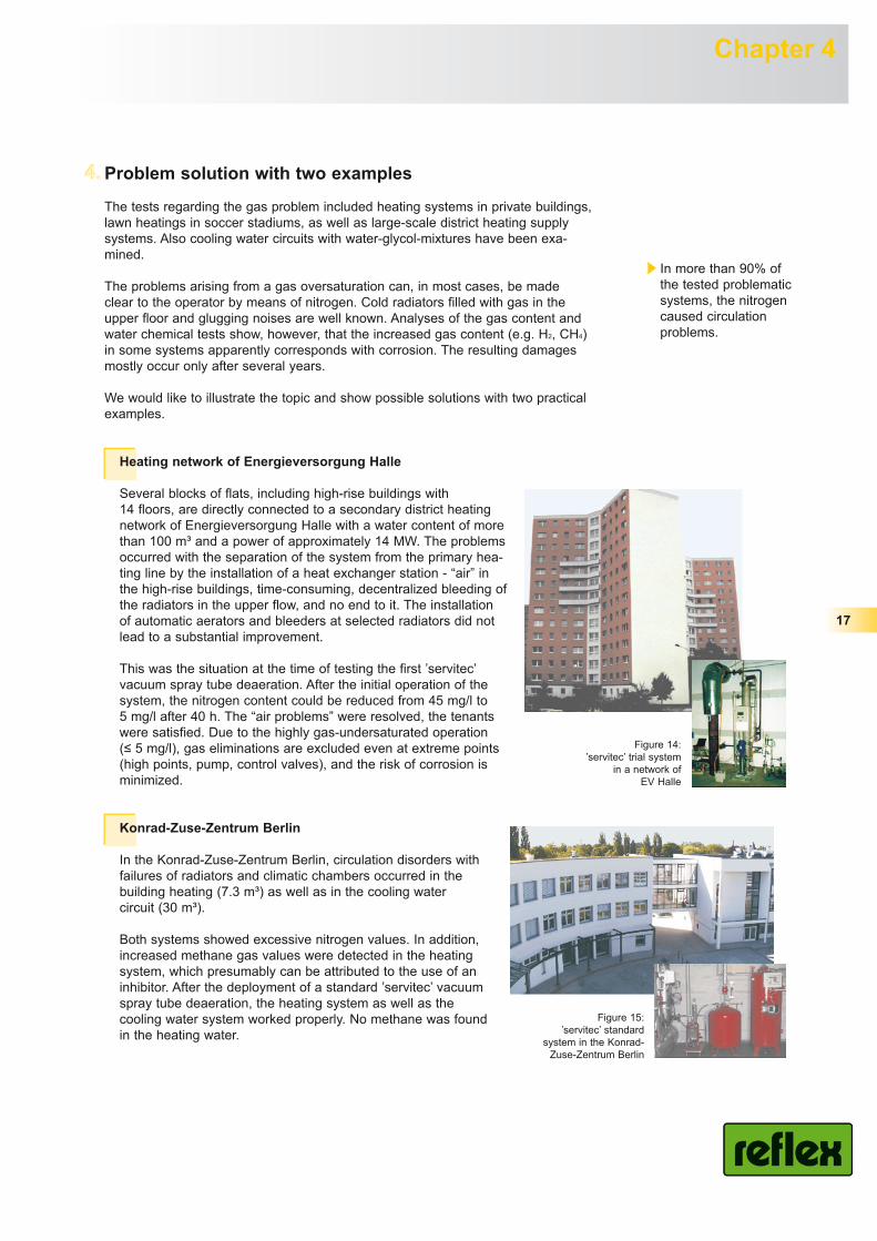
Figure 14:’servitec’ trial system
in a network of EV Halle
Figure 15:’servitec’ standard
system in the Konrad-Zuse-Zentrum Berlin
In more than 90% of the tested problematic systems, the nitrogen caused circulation problems.
4.4. Problem solution with two examples
The tests regarding the gas problem included heating systems in private buildings, lawn heatings in soccer stadiums, as well as large-scale district heating supply systems. Also cooling water circuits with water-glycol-mixtures have been exa-mined.
The problems arising from a gas oversaturation can, in most cases, be made clear to the operator by means of nitrogen. Cold radiators filled with gas in the upper floor and glugging noises are well known. Analyses of the gas content and water chemical tests show, however, that the increased gas content (e.g. H2, CH4) in some systems apparently corresponds with corrosion. The resulting damages mostly occur only after several years.
We would like to illustrate the topic and show possible solutions with two practical examples.
Heating network of Energieversorgung Halle
Several blocks of flats, including high-rise buildings with 14 floors, are directly connected to a secondary district heating network of Energieversorgung Halle with a water content of more than 100 m³ and a power of approximately 14 MW. The problems occurred with the separation of the system from the primary hea-ting line by the installation of a heat exchanger station - “air” in the high-rise buildings, time-consuming, decentralized bleeding of the radiators in the upper flow, and no end to it. The installation of automatic aerators and bleeders at selected radiators did not lead to a substantial improvement.
This was the situation at the time of testing the first ’servitec’ vacuum spray tube deaeration. After the initial operation of the system, the nitrogen content could be reduced from 45 mg/l to 5 mg/l after 40 h. The “air problems” were resolved, the tenants were satisfied. Due to the highly gas-undersaturated operation(≤ 5 mg/l), gas eliminations are excluded even at extreme points (high points, pump, control valves), and the risk of corrosion is minimized.
Konrad-Zuse-Zentrum Berlin
In the Konrad-Zuse-Zentrum Berlin, circulation disorders with failures of radiators and climatic chambers occurred in the building heating (7.3 m³) as well as in the cooling water circuit (30 m³).
Both systems showed excessive nitrogen values. In addition, increased methane gas values were detected in the heating system, which presumably can be attributed to the use of an inhibitor. After the deployment of a standard ’servitec’ vacuum spray tube deaeration, the heating system as well as the cooling water system worked properly. No methane was found in the heating water.
Chapter 4
18
Trink-Water
500MM
TIC TIC
TICTIC
TIC
Hyd
raul
ic lo
ck
5.5. Reflex pressure-maintaining and deaeration systems
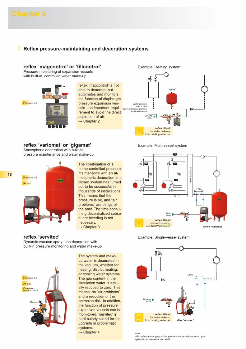
reflex ’magcontrol’ or ’fillcontrol’ Example: Heating systemPressure monitoring of expansion vesselswith built-in, controlled water make-up
reflex ’magcontrol’ is not able to deaerate, but automates and monitors the function of diaphragm pressure expansion ves-sels - an important requi-rement to avoid the direct aspiration of air.→ Chapter 2
reflex ’variomat’ or ’gigamat’ Example: Multi-vessel systemAtmospheric deaeration with built-inpressure maintenance and water make-up
The combination of a pump-controlled pressure maintenance with an at-mospheric deaeration in a closed system has turned out to be successful in thousands of installations. This means that the pressure is ok, and “air problems” are things of the past. The time-consu-ming decentralized subse-quent bleeding is not necessary.→ Chapter 3
reflex ’servitec’ Example: Single-vessel systemDynamic vacuum spray tube deaeration withbuilt-in pressure monitoring and water make-up
The system and make-up water is deaerated in the vacuum, whether for heating, district heating, or cooling water systems. The gas content in the circulation water is actu-ally reduced to zero. This means: no “air problems” and a reduction of the corrosion risk. In addition, the function of pressure expansion vessels can be moni-tored. ’servitec’ is parti-cularly suited for the upgrade in problematic systems.→ Chapter 4
Pressure o.k.
Air out
Pressure o.k.
Pressure o.k.
Air out
Corrosionunder control
Chapter 5
’reflex’
Water pressure min. 1.3 bar
above admission pressure expansion vessel
reflex ’fillset’for water make-up
from drinking water net
Drinking water
Drinking water
tR 70 °C
500
reflex ’variomat’
reflex ’fillset’bei Nachspeisung
aus TrinkWaternetzen
reflex ’fillset’for water make-up
from drinking water net reflex ’servitec’
Note:refl ex offers more types of the products shown above to suit your system’s requirements and size!
19
6.6. Compendium of the chapters
Oxygen is an extremely reactive gas and is as the main cause of corrosion mostly consumed in the system. It occurs (almost) exclusively in dissolved form. Oxygen concentrations > 0.1 mg/l indicate an increased risk for the occurrence of corrosion damages /3/.Nitrogen as an inert gas is mostly responsible for the formation of two-phase flows gas/water. It permanently builds up in the system and leads, for example, to the well-known circulation disorders. Nitrogen values of ≤ 15 mg/l are, in general, unproblematic and can already be reached during the atmospheric deaeration.
Summary Chapter 1
The pressure maintenance plays a central role with respect to the gas pro-blem. It must be closed towards the atmosphere in order to avoid, above all, the absorption of oxygen. Furthermore, it must reliably avoid low pressure and cavitation. Many diaphragm pressure expansion vessels, especially in small installations, are improperly configured with respect to gas and water and are not maintained according to DIN 4807 T 2 /6/. In this area, there is still need for infor-mation and action.The penetration and formation of gases is almost inevitable for closed systems (filling, make-up, diffusion, chemical reactions).Gases must be purposefully dissipated from closed systems through appropriate devices to avoid circulation disorders, erosion, and corrosion. Thereby, a centralized solution is to be preferred. The deaeration must be a one-way street: Gases must be able to exhaust, but air must not be allowed to get in!
Summary Chapter 2
Mechanical air separators can only work effectively if they are installed at high points.Atmospheric deaerators can prevent the formation of free gas bubbles in the circu-lation water. They are the best solution as a central bleeding device, but not for the purposeful oxygen separation. Erosion due to two-phase flow can be avoided to the greatest possible extent.Vacuum deaerators can reduce the overall gas content almost to zero. They com-bat corrosion (reactive gases) as well as erosion (inert gases). High degrees of separation are achieved using dynamic vacuum deaerators.HENRY´s law does not describe the actual gas content, but the maximum possible gas content in the solution.
Summary Chapter 3
The function of Reflex deaeration systems was proved in several series of mea-surements by the Technical University of Dresden in heating, district heating, and cooling circuits.Thanks to the central bleeding and deaeration functions, the installation of decentralized, mechanical air separators is not necessary anymore. The time-con-suming subsequent bleeding at numerous air bleeds is a thing of the past.If system size, investment cost or other reasons do not allow the use of a deaeration system, the best choice is the integration of a mechanic microbubble or air separator at the system’s high point.
Summary Chapter 4 / 5
Chapter 6

FI01
19en
F / 9
5710
12 /
05 -
11 /
1.00
0Te
chni
sche
Änd
erun
gen
vorb
ehal
ten
Real progress is only achieved when man takes care of natural resources.Therefore, we favour materials and production technology which offer maximum environmental compatibility.Taking care of and assuming responsibility for the environment has been and will always be one of the principles of Reflex.
Reflex Winkelmann GmbH
Gersteinstrasse 1959227 AhlenGermany
Phone: +49 23 82 / 70 69 - 0Fax: +49 23 82 / 70 69 - 558www.reflex.de
Reflex – We want the environment to benefit from our progress


