ENERGY STAR ® Building Manual 1 9. Heating and Cooling Revised January 2008 9.1 Overview 2 9.2 Central Cooling Systems 3 Chiller Plant Operations and Maintenance 4 Chiller Plant Retrofits 6 9.3 Central Heating Systems 10 Boiler System Operations and Maintenance 11 Boiler System Retrofits 11 Improving Furnace Efficiency 13 9.4 Unitary Systems 14 Packaged Rooftop Units 16 Split-System Packaged Units 18 Air-Source Heat Pumps 18 Ground-Source, Closed-Loop Heat Pumps 19 9.5 Additional Strategies 20 Air-Side Economizer 20 Energy Recovery 20 Desiccant Dehumidification 20 Night Precooling 21 Cool Storage 22 Evaporative Cooling 22 9.6 Summary 22 Bibliography 23 Glossary G-1
Transcript
ENERG
Y STAR
® Building Manual
1
9. Heating and Cooling
Revised January 2008
9.1 Overview 2
9.2 Central Cooling Systems 3
Chiller Plant Operations and Maintenance 4
Chiller Plant Retrofits 6
9.3 Central Heating Systems 10
Boiler System Operations and Maintenance 11
Boiler System Retrofits 11
Improving Furnace Efficiency 13
9.4 Unitary Systems 14
Packaged Rooftop Units 16
Split-System Packaged Units 18
Air-Source Heat Pumps 18
Ground-Source, Closed-Loop Heat Pumps 19
9.5 Additional Strategies 20
Air-Side Economizer 20
Energy Recovery 20
Desiccant Dehumidification 20
Night Precooling 21
Cool Storage 22
Evaporative Cooling 22
9.6 Summary 22
Bibliography 23
Glossary G-1
ENER
GY
STA
R® B
uild
ing
Man
ual
2
9. H
eati
ng
an
d C
oo
lin
g 9.1 Overview
Although heating and cooling systems provide a useful service by keeping occupants comfort-able, they also account for a significant portion of a building’s energy use—typically about a quarter. However, it is possible to lessen this impact in both central and unitary systems by increasing their efficiency.
This chapter identifies opportunities for improving the performance of heating and cooling systems. Cooling systems generally have higher space-conditioning capacities than heating systems because waste heat from people, lighting, and office equipment supplies a large por-tion of a building’s heating requirement. Although their higher capacities often translate into more opportunities for savings from cooling systems, significant savings can still be had from heating systems.
Following the steps outlined in previous stages of this manual should have reduced cooling and heating loads (Figure 9.1). Many existing systems are oversized to begin with, so it may now be possible to justify replacing the current system with a properly sized one—or retrofitting it to operate more efficiently. When replacing system components, it is extremely important to size the equipment properly to meet current loads. Besides saving energy, proper sizing will likely reduce noise, lower first costs for equipment, and optimize equipment operation, which in turn reduces maintenance costs and extends equipment lifetime. For example, a 1 watt per square foot (W/ft2) reduction in lighting load in a 100,000-ft2 building would allow a chiller capacity reduction of about 23 tons (assuming 80 percent of the waste heat reaches the condi-tioned space). If a typical chiller costs $450 per ton, then a 23-ton reduction would reduce the first cost of a new chiller by more than $10,000. Other load reductions would further reduce the required chiller size. To determine new heating and cooling loads accurately, it may be necessary consult an energy engineer or other expert.
Figure 9.1: The staged approach to building upgrades
The staged approach to building upgrades accounts for interactions among all the energy flows in a building. Each stage affects the upgrades performed in subsequent stages, thus ensuring the greatest energy and cost savings possible. The heating and cooling stage takes advantage of all the load reductions achieved in earlier stages.
Air distribution systems upgrade
Lightingupgrade
HVAC upgradeSupplemental
load reductions
Stages of an integrated upgrade approach
Base
load
Retrocommissioning
New base load
Courtesy: E SOURCE
ENERG
Y STAR
® Building Manual
3
9. H
eating
and
Co
olin
gThe conventional approach to upgrading a heating and cooling system is to address each com-ponent of the system individually. However, addressing the interactions among components using an integrated-system approach ultimately results in superior efficiency, particularly with central systems.
An annual maintenance program is also essential for keeping any heating or cooling system operating efficiently. Clean or replace air filters regularly, verify proper refrigerant levels and airflow, and inspect equipment for obvious malfunctions like stuck dampers.
Although heating and cooling upgrades represent the last stage of building upgrades, they do not signal the end of the process. It is important to make sure the changes implemented continue to provide the intended benefits throughout their useful lifetimes—through periodic recommissioning and further upgrades as needed. See the EPA’s Guidelines for Energy Man-agement Overview at www.energystar.gov/index.cfm?c=guidelines.guidelines_index.
9.2 Central Cooling Systems
Chilled-water systems, found mainly in large buildings, feature separate central chillers and air handlers, with a network of pipes and pumps to connect them (Figure 9.2). Although only 18 percent of all U.S. commercial building floor space is cooled by chillers, about 39 percent of all buildings larger than 100,000 ft2 contain chilled-water systems.
Chillers use one of four types of compressor: reciprocating, scroll, screw, and centrifugal. Reciprocating chillers are the least efficient. Screw and scroll compressors are typically used in applications needing up to 300 tons of cooling capacity. Centrifugal compressors traditionally provide larger capacities, although a new type of centrifugal compressor that employs magnetic bearings breaks this mold to serve the under-300-ton market.
There are no federal minimum efficiency standards for chillers. However, ASHRAE (the American Society of Heating, Refrigerating, and Air-Conditioning Engineers) does provide
Figure 9.2: Typical water-cooled chiller system
The air-handling unit captures heat inside the building and the cooling tower expels it.
g efficiency specifications in its 90.1 standard, “Energy Standard for Buildings Except Low-Rise Residential Buildings,” which is used in many local building codes (Table 9.1).
As counterintuitive as it may sound, focusing on just the efficiency of the chiller will not neces-sarily lead to the most cost-effective savings. Chiller efficiencies do not account for pumps and fans in the cooling system and they apply only to single chillers (80 percent of plants use multiple chillers). Full-load efficiency data is also of little value because chillers rarely run at full load, and integrated part-load data is provided at too few operating points to give an accurate indication of performance. The best way to produce energy and demand savings is to consider the operation of the entire chiller plant using an integrated approach. Energy and demand savings are achievable through improved operation and maintenance of the plant as well as through efficiency retrofits. Note that many chillers that used the now-banned chlorofluorocarbon (CFC) refrigerants have already been either replaced or upgraded to use compliant refrigerants. When a remaining CFC system is finally replaced or upgraded, this presents an opportunity to evaluate other chiller plant modifications that could yield substantial energy savings.
Chiller Plant Operations and MaintenanceThe efficiency of a chiller plant can be improved through both operations and maintenance adjustments.
Use controls to properly sequence chillers. Monitor the capacity of all chillers in the plant and turn chillers on or off so that each one is loaded enough to keep it in its most effi-cient zone (see sidebar, “Sequencing Chillers Yields Savings”).
Monitor outdoor conditions and reset the chilled-water temperature accordingly. This strategy can help match chiller output to the actual load. Note however that this strategy is often disabled by chiller plant operators trying to rectify unrelated plant problems. To help prevent this, show plant operators how to apply and maintain this strategy and explain why it is valuable.
Monitor outdoor conditions and reset the condenser-water temperature accordingly. Higher condenser-water temperatures decrease cooling tower fan power but increase chiller power. The optimum operating temperature occurs at the point where these two opposing trends combine to produce the lowest total power use. However, this point changes with outdoor conditions, so it needs to be adjusted periodically to maintain efficiency.
Table 9.1: ASHRAE 90.1-2001 and 2004 minimum required efficiencies for water-cooled chillers
Many local building codes directly reference ASHRAE 90.1 or require using the International Energy Conservation Code, which has adopted 90.1.
Capacity range
< 150 tons 150 to 300 tons > 300 tons
Chiller type Full load IPLV Full load IPLV Full load IPLV
Centrifugal 0.703 0.670 0.634 0.596 0.576 0.549
Screw and scroll 0.790 0.676 0.718 0.628 0.639 0.572
Reciprocating 0.837 0.696 0.837 0.696 0.837 0.696
Note: IPLV = integrated part-load value. Courtesy: E source; data from ASHRAE
ENERG
Y STAR
® Building Manual
5
9. H
eating
and
Co
olin
g
Take full advantage of available cooling towers. Most chilled-water plants have excess capacity, with one or more cooling towers not operating during low-load periods. To make the most of existing cooling towers, simply run condenser water over as many towers as possible, at the lowest possible fan speed, and as often as possible. This strategy is feasible only for chilled-water systems that include multiple chillers and towers plumbed in parallel—and the ability to vary the speed of the fans. For such systems, open all the condenser-water isola-tion valves at the cooling towers and leave them open. To avoid additional pumping power costs, run only enough condenser-water pumps to maintain adequate flow through the chill-ers. This retrofit strategy does have one drawback for two-speed fans: It causes additional fan cycling (between half speed and off, and between half speed and full speed). This in turn leads to additional wear and tear on motors and gears.
Inspect tubes annually and clean as needed, or use automatic tube-cleaning equipment. As a chiller runs, water may leave behind scale, algae, or slime on the inside of the condenser tubes (buildup is typically not a problem in the evaporator tubes because that is a closed system). These deposits can decrease both the efficiency and the capacity of the chiller by reducing heat-transfer efficiency. Periodic chemical or ozone treatments can help keep con-denser tubes clear. Another option is automatic cleaning equipment that inserts thumb-sized nylon brushes into each condenser tube—catch baskets epoxied to the ends of the tubes col-lect the brushes. These brushes are slightly larger than the inside diameter of the tubes, so they brush the whole length of the tube as they are propelled by the water flow.
Energy and maintenance savings depend on the chemical or manual treatment that would otherwise have been used—the more deposits that would have built up, the greater the savings. A condenser fouled to the point that the temperature increases 5 degrees results in a 5 percent decrease in capacity and a 5 percent increase in power requirements. In some older machines, refrigerant tubes in the evaporator can become fouled by oil in the refrigerant—oil separators address this problem and are standard equipment on newer systems.
Prevent scale formation in cooling towers. Scaling, corrosion, and biological growth all impede tower efficiency and increase maintenance costs from the resultant condenser fouling and loss of heat transfer. Chemical treatments typically mitigate these problems, but nonchemical treatment technologies, such as ozone generators and ultraviolet irradiation, are also available.
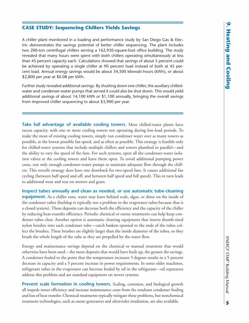
CASE STUDY: Sequencing Chillers Yields Savings
A chiller plant monitored in a loading and performance study by San Diego Gas & Elec-tric demonstrates the savings potential of better chiller sequencing. The plant includes two 200-ton centrifugal chillers serving a 162,930-square-foot office building. The study revealed that many hours were spent with both chillers operating simultaneously at less than 45 percent capacity each. Calculations showed that savings of about 5 percent could be achieved by operating a single chiller at 90 percent load instead of both at 45 per-cent load. Annual energy savings would be about 34,500 kilowatt-hours (kWh), or about $2,800 per year at $0.08 per kWh.
Further study revealed additional savings. By shutting down one chiller, the auxiliary chilled-water and condenser-water pumps that served it could also be shut down. This would yield additional savings of about 14,100 kWh or $1,100 annually, bringing the overall savings from improved chiller sequencing to about $3,900 per year.
ENER
GY
STA
R® B
uild
ing
Man
ual
6
9. H
eati
ng
an
d C
oo
lin
g Chiller Plant RetrofitsChilled-water plants are complex and thus present many retrofit efficiency opportunities. As a general approach, thinking upstream through possible retrofit opportunities—starting at the valves and ending at the cooling tower fan—can yield upstream capital cost savings and energy savings. For example, by reducing resistance in the piping system, a designer might be able to reduce capital costs by specifying a smaller pump and a smaller chiller. However, to improve the overall efficiency of a chiller plant, an integrated system approach must be used. This is important for two reasons. First, it is difficult to make generalizations about specific opportunities—creating the most cost-effective chiller plant for a particular building often requires a designer to consider energy and demand prices, building load characteristics, local climate, building design, operating schedules, and the part-load operating characteristics of the available chillers. Second, modifying the design or operation of one set of components often affects the performance of other compo-nents of the system. For example, increasing the chilled-water flow can improve chiller efficiency, but the extra pumping power required can result in an overall reduction in system efficiency.
To illustrate the challenge of improving a chiller plant’s overall efficiency, consider the case of a designer who switched a chiller condenser-tube bundle from two-pass flow to four-pass flow in order to improve chiller efficiency. That change indeed improved chiller efficiency from 0.62 kilowatts (kW) per ton to 0.60 kW per ton, but it also added 28 feet of pressure drop to the chilled-water flow stream—and thus increased the required pumping power. As shown in Table 9.2, this produced a net chiller plant energy savings at full load. However, because this particular building featured a constant-flow system, at the typical 75-percent load condi-tion there was a net plant energy-use increase. The net effect was even worse at lower loads. Although the designer had intended to reduce energy consumption by improving chiller effi-ciency, the “improvement” wound up increasing overall building energy consumption.
Accounting for all the variables in a chiller plant can be a daunting task, so one of the best options for producing an optimal chilled-water system is to use a building energy performance simulation package. These computer programs (see sidebar, “Resources: Chillers”) perform the numerous and complex calculations needed to evaluate how buildings use energy. The most sophisticated programs can calculate building energy consumption hour by hour for an entire year. That allows designers to see how modifications to any of the building’s systems—including the chilled-water system—will affect the building’s annual energy consumption. These packages also account for interactions among building components, which allows building designers to experiment with a variety of combinations of efficiency strategies and determine which ones pro-duce the most cost-effective building. Designers and their clients may seek to amortize the cost of
Table 9.2: The perils of piecemeal chiller improvements
By not considering the interaction of all chiller components, this conversion to a two-pass flow condenser-tube bundle resulted in a net energy use increase at the more typical load factor of 75 percent.
Post-conversion power consumption
Component Full load (kW) 75% load (kW)
Chiller -8.80 -6.60
Pumps 8.60 8.60
Chiller + pumps -0.20 2.00
Note: kW = kilowatt. Courtesy: E source
ENERG
Y STAR
® Building Manual
7
9. H
eating
and
Co
olin
gsimulating building performance by using simulations after the building is occupied—to verify savings, optimize HVAC system control, and identify malfunctions in building systems. Several HVAC equipment manufacturers also offer energy simulation software.
The following list presents efficiency opportunities to consider for chilled-water systems.
Replace standard valves with low-friction units to reduce flow resistance for the chilled water. This measure reduces pump energy use and returns less heat to the chiller. Where valves control flow by inducing pressure drop, consider converting to variable-speed controls, trim-ming the impeller, or staging pumps instead. Then eliminate or completely open the valves.
Insulate chilled-water pipes. Insulation helps ensure that the chilled water only absorbs heat from the spaces where it is intended to do so.
Replace standard-efficiency or oversized pumps with highly efficient units sized for the newly reduced loads. Most induction motors that drive pumps reach peak efficiency when about 75 percent loaded, and are less efficient when fully loaded. Thus, wherever possible, size pumps so that much of their operating time is spent at or close to their most efficient part-load factor. If a pump is oversized, then it likely operates at an inefficient loading factor.
RESOURCES: Chillers
DOE-2
www.doe2.com
This hourly building energy performance simulation software was developed by the Simulation Research Group at Lawrence Berkeley National Laboratory. It takes some practice to become adept at this software and running a variety of scenarios can be quite time-consuming, so con-sider hiring consultants who specialize in performing these evaluations.
eQUEST
www.doe2.com/equest
Developed as part of the Saving by Design incentive program offered by California utilities, eQUEST is a free software package that provides a “window- and wizard-driven” front end to DOE-2. Although easier to use than DOE-2, it allows users to access DOE-2’s full capabili-ties to model many variables that affect a chiller’s performance. It can also be used to assess and help minimize building cooling loads. Savings achieved from proposed systems are compared with a modeled baseline chiller plant set to conform with local building codes.
CoolTools Chilled Water Plant Design and Specification Guide
This free guide sponsored by Pacific Gas & Electric Co. is written for technical designers and offers direction on many of the options available in designing a chilled-water plant.
Danfoss Turbocor
www.turbocor.com
This is the only magnetic-bearing chiller compressor. Turbocor manufactures and supplies the compressor direct to end users for retrofits and to chiller manufacturers who incorpo-rate the compressor into new chillers and offer them for retrofits.
g Control chilled-water pumps with variable-speed drives (VSDs). VSDs can ensure that pumps are performing at maximum efficiency at part-load conditions. As with fan sys-tems, the power required to operate a pump motor is proportional to the cube of its speed. For example, in a pump system with a VSD, a load reduction that results in a 10 percent reduction in motor speed reduces energy consumption by 27 percent: 1 – (0.9)3 = 0.27. However, it is necessary to ensure that flow rates through chillers are maintained at safe levels. With sophisti-cated controls, lower chilled-water flow rates enabled by VSD pumps can also be coordinated with a chilled-water temperature reset strategy to meet loads accurately and efficiently. For example, low loads might be most efficiently met by creating colder chilled water and reducing the flow rate to save pump energy.
Upgrade the chiller compressor. For a centrifugal compressor, install a VSD. This will allow the chiller to run at lower speeds under part-load conditions, thereby yielding a higher efficiency than is typically achieved by ordinary centrifugal chillers that control part-load oper-ation with inlet vanes. However, a VSD may not be cost-effective in applications where there are extended periods with very low loads (10 percent of full load). In these cases, consider installing a separate small chiller just for these loads.
For reciprocating and screw chillers, replace the existing compressor with one that uses new magnetic bearing technology. These achieve much better efficiency than any other compressor type in the under-300-ton capacity range. Chillers using magnetic bearing compressors can achieve an integrated part-load value (IPLV) of 0.3699 kW/ton, as compared with an IPLV of 0.6000 kW/ton for standard screw- and scroll-based chillers, producing significant savings.
For example, at the San Diego East County Family Resource Center, a single 80-ton magnetic-bearing compressor replaced two reciprocating compressors on an existing 88-ton air-cooled chiller after one of the reciprocating compressors failed. Before-and-after monitoring showed an efficiency gain of 0.41 kW/ton. Because cooling loads were relatively low—1,347 equiva-lent full-load cooling hours (a metric used to estimate annual energy use for cooling in a building)—the chiller was oversized by about 30 tons. The compressor replacement produced an estimated payback period of 4.7 years (or 2.8 years with incentives from the San Diego Regional Energy Office) and an ongoing energy savings of about $8,000 per year.
For chillers without a VSD, use low-voltage soft starters. The motor windings of constant-speed compressors experience great stress when the chiller is first started due to the high inrush of current. Over time this can lead to motor failure. Soft starting gradually raises the voltage and current to avoid the high inrush. Soft starting itself does not save energy, but it does enable shutting off chillers that are otherwise left running because operators are con-cerned about wear and tear from frequent starts.
Replace an old or oversized standard-efficiency chiller with a properly sized high-efficiency water-cooled unit. If the existing chiller is nearing the end of its life or is in need of substantial maintenance, consider retiring it early to capitalize on the savings that a new high-efficiency model can provide. The annual energy cost for operating a chiller can be as much as one-third of its purchase price, so even a modest improvement in efficiency can yield substantial savings and attractive paybacks. For example, paying an extra $6 per ton for each 0.01 kW/ton improvement to raise the efficiency of a 500-ton chiller from 0.60 kW/ton to 0.56 kW/ton would increase that machine’s first cost by $12,000. But it would also reduce operating costs by $3,000 per year, yielding a four-year simple payback. This can be particu-larly fruitful if the existing chiller is already oversized or if load reductions achieved through other stages in the building upgrade process allow the chiller to be downsized.
ENERG
Y STAR
® Building Manual
9
9. H
eating
and
Co
olin
gWhen replacing an existing chiller, select one that will be most efficient under the conditions it is likely to experience. Even though chiller performance can vary dramatically depending on loading and other conditions, designers frequently select chillers based on full-load, standard-condition efficiency. However, chillers spend most of their operat-ing time at 40 to 70 percent load under conditions that are often considerably different from standard conditions. For example, when San Diego Gas & Electric reviewed the performance of 21 chiller plants, it found that at 11 of the sites more than one chiller was running at less than 50 percent of design load most of the time. To select the chiller that will have the lowest operating costs, determine what the actual operating conditions are likely to be and then con-sider how efficiently the unit will operate under those conditions. In many cases, VSD chillers along with VSD pumps and fans are highly cost-effective.
Install plumbing to connect multiple cooling towers or multicell towers in parallel and VSDs to control cooling tower fans. This step allows the chiller plant to use excess cooling tower capacity at part-load conditions and save on fan energy, as described in the Chiller Plant Operations and Maintenance section.
Install water-side economizers to allow cooling towers to produce chilled water when weather conditions permit. Under the right conditions, water-side economizers can save a lot of energy. In cool, dry climates, they can provide more than 75 percent of the cooling requirements; in warm climates they may provide only 20 percent. The most common type is an indirect economizer that uses a separate heat exchanger, typically of the plate-and-frame type (Figure 9.3). It allows for a total bypass of the chiller, transferring heat directly from the chilled-water circuit to the condenser-water loop. When the wet-bulb temperature is low enough, the chiller can be shut off and the cooling load may be served exclusively by the cooling tower.
Again, before pursuing any of the opportunities listed above, it is important to evaluate the performance of the chiller plant as an integrated system. Although an integrated approach requires more effort than simply picking measures independently, it can produce significant savings (see sidebar). Note that for the opportunities listed here that involve adding VSD
Figure 9.3: Indirect water-side economizer
Inserting a heat exchanger between the cooling tower and air-handling unit enables the con-trols to bypass the chiller when outdoor temperatures are low enough.
Condenserwater pump
Chilledwater pump
Air-handling unitcooling coil
Air
Courtesy: E SOURCE; adapted from EPA
Cool water
Very cool water
Plate and frameheat exchanger
Bypassed chiller
Cooling tower
Fan
ENER
GY
STA
R® B
uild
ing
Man
ual
10
9. H
eati
ng
an
d C
oo
lin
g
9.3 Central Heating Systems
Two types of equipment are used to provide central heat for buildings: boilers and furnaces. Boilers, which produce hot water or steam that is then distributed throughout a building, heat about 32 percent of all U.S. commercial floor space (Figure 9.4). Typically there are more opportunities to improve the efficiency of boiler systems due to their more complicated nature, as compared to furnaces.
Furnaces heat air (instead of water) and distribute it to occupied spaces. Note that in commer-cial applications, the term “furnace” applies to several types of equipment, which together heat about 30 percent of the floor space in U.S. commercial buildings. Central furnaces, though they serve a relatively small percentage of heated commercial space, offer the greatest savings opportunities amongst furnaces because they are the only type that heats an entire building. Other types, such as duct furnaces and vertical-air-turnover furnaces, supply heat to only a limited area of the building.
Other heating systems, such as those contained in packaged rooftop units (see section 9.4), typically do not offer savings opportunities.
components, control upgrades may also be required. VSD pumps, fans, and compressors provide greater operations flexibility and efficiency, but the control system must coordinate their operations with the rest of the system—existing controls may not be able to provide the advanced functions necessary for efficient operation.
CASE STUDY: A Chiller Plant Overhaul
The cooling plant at the San Diego Crime Lab was in need of an upgrade. The chiller plant was 18 years old, used two outdated 130-ton air-cooled reciprocating chillers, and was wasting energy and increasing demand charges. On top of these problems, more cool-ing capacity was required for a planned laboratory expansion. One option was to replace the reciprocating compressors with air-cooled screw compressors. Based on a whole-plant analysis, this retrofit would supply the needed capacity—but with only moderate energy and demand savings. After further evaluation of the existing equipment and the facil-ity’s needs, the crime lab opted instead to install an all-variable-speed water-cooled chiller plant. This included variable-speed cooling tower fans and pumps on both the chilled- and condenser-water side, as well as a magnetic-bearing compressor that could operate at variable speeds.
The new chiller plant, including the pumps and fans, performed at an average efficiency of 0.538 kilowatts (kW) per ton. Traditionally, a plant efficiency of 0.7 to 0.8 kW/ton is considered good in the under-300-ton size range, and most plants operate at 1.0 kW/ton or above. The old air-cooled chiller plant was measured as using around 1.48 kW/ton. The incremental cost and savings between a new standard chiller plant (using air-cooled screw compressors without variable-speed equipment) and the all-variable plant produced a pay-back of five years based on energy and demand savings alone. Incentives provided by San Diego Gas & Electric further reduced the incremental payback to two years. The ongoing estimated annual energy and demand savings amount to about $65,000.
ENERG
Y STAR
® Building Manual
11
9. H
eating
and
Co
olin
g
Boiler System Operations and MaintenanceThe following list of operation and maintenance measures are important parts of the overall boiler system upgrade strategy and can provide significant energy savings:
■ Establish a total-system water treatment program. This will help prevent the formation of deposits that degrade heat transfer and increase friction.
■ Periodically check the air-fuel ratio. If it is not cost-effective to install a boiler combustion monitoring system, periodically check and calibrate the stack temperature, excess air, CO, CO2, opacity, and NOx using portable monitoring equipment. The data will reveal inef-ficiencies in the combustion process.
■ Periodically reset the boiler pressure. If temperature/pressure reset controls are not used, period-ically assess the temperatures required and reset boilers to the minimum necessary pressure.
■ Assess feedwater and blowdown rates. Where it is not feasible or economical to install an automatic blowdown control system (see “Boiler System Retrofits”), establish the feedwa-ter and blowdown rates described in the Boiler and Pressure Vessel Code developed by the American Society of Mechanical Engineers (see www.asme.org). This will help remove dissolved solids that might otherwise damage equipment and waste energy.
■ Identify and repair steam leaks. Leaks waste energy and can damage surrounding spaces.
■ Establish a program for systematically inspecting, testing, and repairing steam traps. Leaking steam traps waste energy by allowing steam to escape into the condensate return line, thus preventing the steam from delivering heat where intended.
■ Remove scale from boiler heat-exchange surfaces. Scale decreases the heat transfer capability of heat exchangers.
Boiler System RetrofitsConsider replacing an existing boiler with a new, energy-efficient unit sized to reflect loads reduced through other stages of the building upgrade process. While the average gas boiler in the commercial stock has a combustion efficiency (100 percent minus flue losses) of 76 percent, new gas-fired commercial boilers have an average combustion efficiency of 80 percent, and high-efficiency boilers built with condensing heat exchangers have combustion efficiencies as high as 90 percent.
Figure 9.4: A typical boiler
In this water-tube boiler, feedwater flows through tubes where hot gases from the combustion process heat the water. Exhaust gases leave through the flue.
g The current federal minimum efficiency standards for commercial boilers took effect on Janu-ary 1, 1994. For boilers with a rated maximum input capacity of at least 300,000 Btu per hour, the combustion efficiency at the maximum rated capacity must be at least 80 percent for gas-fired equipment and 83 percent for oil-fired equipment.
Although the federal standards use combustion efficiency to measure the efficiency of boilers, the EPA qualifies boilers for the ENERGY STAR program based on their annual fuel utilization effi-ciency (AFUE). AFUE estimates energy use more accurately than combustion efficiency because it includes flue losses, off-cycle losses, and equipment-jacket losses. Qualified boilers must have an AFUE of at least 85 percent (see www.energystar.gov/index.cfm?c=boilers.pr_boilers).
Because efficient models require corrosion-resistant materials and sophisticated controls, they cost up to three times as much as conventional boilers. However, a properly sized condensing boiler system will generally beat out a less efficient boiler system in terms of life-cycle cost (boilers have an average life of 25 years). To determine whether to replace a boiler system, calculate the expected energy savings by comparing rated energy consumption at various loads for the old and new boiler systems. These calculations can be complicated, so it may be useful to consult an engineering firm or boiler manufacturer for assistance.
Several small boilers can also be grouped together in parallel to provide staged heating capacity. This approach is usually more economical and efficient than using a single large boiler because:
■ The boilers can be staged to operate at or near their highest efficiency points.
■ Small boilers are more efficient than large commercial boilers.
■ Multiple boilers provide redundancy, which can reduce system downtime.
■ Small boilers can reduce installation costs because each boiler is small enough to be handled without a crane.
The multiple-boiler approach can also be used as a retrofit measure to improve the seasonal efficiency of large, inefficient, aging boilers. A small high-efficiency “front-end” boiler can be installed in tandem with the old one—the small boiler serves the base heating load and the large boiler only fires up when needed to meet high demand.
Where boiler replacement is not feasible, there are many retrofit options that will improve the efficiency of an existing boiler system:
■ Insulate hot-water distribution lines. Insulation reduces heat loss to unconditioned spaces, thereby optimizing the delivery of heat to the intended portions of the building.
■ Install VSD controls on hot-water distribution pump motors. This measure is most effective in large buildings where pumping energy is significant and when used in conjunction with condensing boilers. Be careful with noncondensing boilers because low flow rates can cause flue gas condensation and corrosion in the boiler.
■ Install a combustion monitoring and control system. Use the monitoring data to trim boiler excess air and/or install automatic oxygen trim controls. To learn more about flue gas moni-toring and burning tuning, see the U.S. Department of Energy (DOE) Industrial Tech-nologies Program Steam Tip Sheet #4 at www1.eere.energy.gov/industry/bestpractices/pdfs/steam4_boiler_efficiency.pdf.
■ Install temperature/pressure reset controls. These provide significant energy savings by match-ing the supply of steam or hot water with the demand for heat—by resetting the system
gtemperature or pressure based on outdoor temperature. If outdoor temperature increases, the system water temperature or steam pressure is lowered.
■ Install controls to set back supply temperature during unoccupied hours. This saves energy by reducing heating when maintaining occupant comfort is not required.
■ Install an automatic blowdown control system. This helps remove dissolved solids that can damage equipment and lead to energy waste, depending on the concentrations present. See the DOE Steam Tip Sheet #23 at www1.eere.energy.gov/industry/bestpractices/pdfs/steam23_control_system.pdf. When using continuous blowdown instead, install a heat exchanger to warm feedwater with heat recovered from blowdown.
■ Install a stack economizer. A stack economizer captures waste heat in the exhaust flue gases and uses it to preheat the boiler feedwater. This measure is typically only cost-effective for very large (more than 2 million Btu per hour capacity) systems. When natural gas fuels the boiler, maintain the stack temperature at at least 250° Fahrenheit to avoid water condensa-tion in the flue gases.
■ Install baffle inserts. These induce combustion gases to flow in a turbulent spiral pattern, which increases heat-transfer efficiency.
■ Install outside-air intake vents for the boiler. This reduces or eliminates building air infiltra-tion caused by boiler operation.
■ For steam systems, use the DOE Steam System Scoping Tool. This software, available at www1.eere.energy.gov/industry/bestpractices/software.html, quickly evaluates the entire steam system operation and suggests a range of ways to save steam energy and boost productivity. It also compares an existing system to identified best practices and evaluations of similar facilities. Also see the DOE’s collection of Steam Tip Sheets at www1.eere.energy.gov/industry/bestpractices/tip_sheets_steam.html for other improvement ideas.
■ Insulate steam distribution and condensate return lines. Insulation will prevent heat loss through the system. The DOE provides the 3E Plus software tool at www1.eere.energy.gov/industry/bestpractices/software.html to calculate how much insulation is needed to conserve energy and avoid the expense of overinsulation.
■ Install wide-deadband thermostats for unbalanced single-pipe steam systems. Conventional ther-mostats with shorter deadbands may not cycle on the boiler long enough for steam to fill the entire distribution line, resulting in insufficient heating at the end. But increasing the ther-mostat setting to compensate causes overheating near the start of the line. Wide-deadband thermostats will produce longer on and off cycles and provide more even heating.
Improving Furnace EfficiencyFurnaces are usually fueled by gas or oil; electric furnaces are rare and generally more expensive to operate. Although furnaces in the existing buildings stock have an average AFUE of only 76 percent, new gas-fired commercial furnaces have an average AFUE of 80 percent, and high-efficiency furnaces built with condensing heat exchangers have AFUEs as high as 92 percent.
The current federal minimum efficiency standards for commercial furnaces took effect on Jan-uary 1, 1994. For furnaces of 225,000 Btu per hour capacity or greater, the standards specify a steady-state or thermal efficiency (100 percent minus flue losses) of at least 80 percent for gas-fired equipment and at least 81 percent for oil-fired equipment at their maximum rated input capacity. Note that these efficiency ratings do not account for cycling losses, losses through the
g central heater’s cabinet, or distribution losses. Although the standards only specify thermal effi-ciency, manufacturers can also include AFUE, which accounts for cycling and cabinet losses.
Residential warm-air gas furnaces are sometimes used in small commercial applications. The current federal standard for these units became effective on January 1, 1992, and establishes a minimum efficiency of 78 percent AFUE for units with an input rating of less than 225,000 Btu per hour. A new standard was set in November 2007—to become effective in 2015—raising the minimum efficiency to 80 percent AFUE. For more information on this change, see the DOE’s Residential Furnaces and Boilers web page at www.eere.energy.gov/buildings/appliance_standards/residential/furnaces_boilers.html.
To improve furnace system efficiency:
■ Consider replacing the existing furnace with a new, energy-efficient model. It may be possible to downsize the furnace based on load reductions achieved through other stages of the building upgrade process.
■ Install controls to set back supply temperature during unoccupied hours. This saves energy by reducing heating when maintaining occupant comfort is not required.
■ For electric furnaces, install two-stage setback controls. In spaces where the temperature is reduced during unoccupied periods, the electric demand needed to bring the space back to its original temperature can be significant. In this case, if the local electric rate structure includes demand charges, install a two-stage setback thermostat with staged supplemental heat and a program-mable demand limiter to prevent demand peaks in the morning. Also consider alternatives to resistance heating to reduce heating costs and environmental impact.
9.4 Unitary Systems
Unitary equipment cools about 70 percent of air-conditioned commercial buildings in the U.S. Unitary equipment is factory assembled, available as single-packaged or split-system units, and may take the form of a heat pump (providing both heating and cooling) or an air conditioner. Unitary systems include an evaporator, blower, compressor, and condenser. Some unitary air con-ditioners also include an electric resistance or gas heater section. The systems are typically cabinet- or skid-mounted for easy installation and range in cooling capacity from about 1.5 to 130 tons.
Compared to central chiller plants, unitary systems do not last as long (median lifetime of 15 years compared to 20 to 23 years for chillers) and are less efficient. Unitary systems are gener-ally used in buildings up to three stories that have small cooling loads, such as retail spaces, small office buildings, and schools.
Generally speaking, it is not feasible to convert a building from a unitary to a central chilling sys-tem. However, it is not always necessary to replace an old unit with a new one of the same type. For example, a packaged rooftop air conditioner can be replaced with an air-to-air heat pump.
Commercial buildings typically have unitary systems with cooling capacities greater than 5 tons. These systems are rated by energy-efficiency ratio (EER), which is a measure of full-load effi-ciency at conditions specified by the Air-Conditioning and Refrigeration Institute. Some build-ings use residential-sized unitary systems (under 5 tons, using single-phase power) because of space requirements, physical limitations, or for small additions. Residential-sized systems are rated by seasonal energy-efficiency ratio (SEER), a seasonally-adjusted value. For both EER and
gSEER, a higher number indicates a higher efficiency. ENERGY STAR qualified residential air conditioners have a SEER of at least 14 (see www.energystar.gov/index.cfm?c=cac.pr_central_ac for more information).
Three-phase equipment under 5 tons falls into its own category in the federal standards—although designed for the commercial market, these units use the residential SEER rating. ENERGY STAR qualified three-phase equipment under 5 tons must have a SEER of at least 13 (see www.energystar.gov/index.cfm?c=lchvac.pr_lchvac for more information).
The current U.S. federal standard established in 1992 requires manufacturers to produce com-mercial air-cooled air conditioners and heat pumps at the minimum efficiencies specified in Table 9.3. The Energy Policy Act of 2005 set new federal standards for commercial packaged rooftop units with capacities greater than 65,000 Btu per hour that will take effect on January 1, 2010. For smaller three-phase equipment, a rule-making is in progress to determine whether new standards should be set for this size category. Note that federal standards do not cover geo-thermal heat pumps, although ASHRAE 90.1 requires that those with a cooling capacity below 135,000 Btu per hour have a minimum cooling efficiency of 13.4 EER and a minimum heating coefficient of performance (COP) of 3.1.
Table 9.3: Federal efficiency standards for commercial packaged air-cooled air conditioners and heat pumps
The U.S. Energy Policy Act of 2005 added a “very large” category as part of the update of the standards for commercial packaged air-cooled equipment, in addition to increasing the mini-mum efficiency levels for existing size categories. All equipment listed here uses three-phase power. ENERGY STAR criteria will likely change for <5-ton equipment when the new minimum standards become effective.
Federal minimum standards
Federal size category
Equipment type System design
Effective January 1, 1994
Effective June 16, 2008
Effective January 1, 2010
ENERGY STAR minimum criteria
< 65 kBtu/h, < 5 tons
Air conditioner
Split system SEER 10.0 SEER 13.0 — SEER 13.0a
Single-packaged unit SEER 9.7 SEER 13.0 — SEER 13.0a
Heat pump
Split system SEER 10.0 & HSPF 6.8
SEER 13.0 & HSPF 7.7
— SEER 13.0 & HSPF 7.7a
Single-packaged unit SEER 9.7 & HSPF 6.6
SEER 13.0 & HSPF 7.7
— SEER 13.0 & HSPF 7.7a
Small (65 to < 135 kBtu/h; 5 to 11.25 tons)
Air conditioner
Split system and single-packaged unit
EER 8.9 — EER 11.2 EER 11.0b
Heat pump
Split system and single-packaged unit
EER 8.9 & COP 3.0
— EER 11.0 & COP 3.3
EER 10.1 & COP 3.2b
Large (135 to < 240 kBtu/h; 11.25 to 20 tons)c
Air conditioner
Split system and single-packaged unit
EER 8.5 — EER 11.0 EER 10.80b
Heat pump
Split system and single-packaged unit
EER 8.5 & COP 2.9
— EER 10.6 & COP 3.2
EER 9.3 & COP 3.2b
Very large (240 to < 760 kBtu/h; 20 to 63 tons)
Air conditioner
Split system and single-packaged unit
— — EER 10.0 —
Heat pump
Split system and single-packaged unit
— — EER 9.5 & COP 3.2
—
Notes: COP = coefficient of performance; EER = energy-efficiency ratio; HSPF = heating seasonal performance factor; kBtu/h = thousand Btu per hour; SEER = seasonal energy-efficiency ratio; ton = 12,000 Btu/h. a. Effective January 1, 2004; b. Effective January 1, 2002; c. Energy Star criteria apply to equipment of capacity up to 250 kBtu/h.
Courtesy: E source; data from U.S. Department of Energy and EPA
g Regardless of the equipment chosen, it is important to commission the overall system to ensure its proper operation from the onset as well as to maintain it properly over time (see side-bar). Comprehensive testing, adjusting, and balancing the installed unit and its controls will maximize efficiency and comfort. Conducting regular tune-ups, correcting refrigerant charge, cleaning and adjusting the system to correct airflow and improve heat transfer, and verifying economizer operation can yield surprising energy savings at low cost. The Consortium for Energy Efficiency offers installation guidelines for commercial air-conditioning equipment at www.cee1.org/com/hecac/hecac-spec.php3. Testing, adjusting, and balancing contractors; general HVAC service contractors; and those who use specialized diagnostic products to spe-cifically measure refrigerant charge and airflow levels can perform commissioning and main-tenance services.
Packaged Rooftop UnitsAbout half of all U.S. commercial floor space is cooled by self-contained, packaged air-conditioning units. Often called single-packaged units or rooftop units (RTUs), most sit on rooftops, but they can also be installed on a concrete pad at ground level. Typical units include a blower section, filter bank, evaporator coil, at least one compressor (larger units often have multiple compressors to improve load matching), and an air-cooled condenser section. Evapo-ratively cooled condensers are used to achieve higher efficiencies (Figure 9.5). They may also come equipped with a natural gas or electric heating section—gas models, depending on local energy prices, are generally more economical. When replacing a packaged unit that uses elec-tric resistance heat, consider using a heat pump instead because it may be more cost-effective.
All newer packaged rooftop units are equipped with factory-installed microprocessor controls. These controls make maintaining equipment easier and improve the energy efficiency of both the unit and the overall HVAC system. Control features include temperature setback and on/off scheduling. Large systems have variable-air-volume capability (see Chapter 8, “Air Distri-bution”). Also, most units have an optional communication interface for connection to an energy management system or to a demand-controlled ventilation system.
Selecting new high-efficiency models. Efficiency levels for packaged rooftop units have gradually increased over the past 15 years. In the small size range, the number of units with an EER of at least 10.4 has grown from only 14 percent of available models in 1993 to at least 65 percent in 2007. Units in this size range now have EERs as high as 12.7—so upgrading older units to a new high-efficiency model can produce substantial long-term energy savings. For
CASE STUDY: Diagnostic Service Proves Its Value
Air-conditioning tonnage and airflow-delivery systems are not always matched properly. A contractor certified to use a diagnostic tool that measures refrigerant charge and airflow levels received a report from the Poultry Palace and Deli in El Cajon, California, complain-ing that its air-conditioning system was not working. Two other companies had unsuc-cessfully attempted to repair the system. The certified contractor arrived on the site and determined that the refrigerant charge was correct, but the new 5-ton air conditioner had been coupled with a duct system capable of delivering only 3 tons of airflow. The service technician said he would not have found the problem had it not been for the diagnostic tool. The technician relayed the information to the customer, who authorized the repairs. Once repairs were made, the system was able to meet the cooling load.
example, a typical office building in Kansas City, Missouri, that has 10 standard 25-ton packaged units with EER ratings of 10 could save almost $30,000 annually by upgrading to units with EERs of 12. Note that since packaged rooftop units are primarily used for cooling, those that also provide heating generally do not offer a high-efficiency option for the heating component.
When replacing broken equipment or evaluating early retirement of working equipment, use the free web-based life-cycle cost estimation tool from the Federal Energy Management Pro-gram (www1.eere.energy.gov/femp/procurement/eep_unitary_ac_calc.html) to see how much energy high-efficiency models will save. After entering data for a specific high-efficiency unit and location, the tool estimates life-cycle cost, simple payback, and other metrics as compared to a standard unit that the user selects. Equipment manufacturers or engineering consultants can provide more detailed assistance. The EPA also establishes ENERGY STAR program crite-ria for high-efficiency commercial air conditioners (Table 9.3) and provides a list of qualified units at www.energystar.gov/index.cfm?c=lchvac.pr_lchvac.
Upgrading existing rooftop units. Upgrading existing packaged rooftop units is typi-cally not feasible due to the cost and complexity of retrofitting components within a unit. However, there is one option that can be retrofitted onto the outside of a unit. Called the EER+, it is a heat-exchange module that can be retrofitted onto both existing air-cooled air conditioners and heat pumps to increase their efficiency. Made by Global Energy Group, a manufacturer of energy-efficient cooling equipment, it works by capturing waste condensate
Figure 9.5: Components and features of efficient packaged rooftop unit design
Manufacturers can incorporate several design features to produce high-efficiency units.
Courtesy: E SOURCE
CondenserEvaporatively cooled,oversized to reducecondensing temperatureand compression ratio,designed for smoothairflow
Condenser fansHighly efficient propellerfans and motors, sized forefficient operation at part load
Condenserair out
Filters & cooling coilsGenerously sized for lowvelocity, easy access forcleaning
EconomizerWith reliable damper controls
Outsideair in
Return air in
Supply air fanHighly efficientbackward-curved airfoilblades, efficient motor,variable-speed drive control
CompressorsMultiple compressors,sized for efficientoperation at part load
Condenser air inDouble skin constructionContains two or more inchesof insulation, light colorreflects solar heat
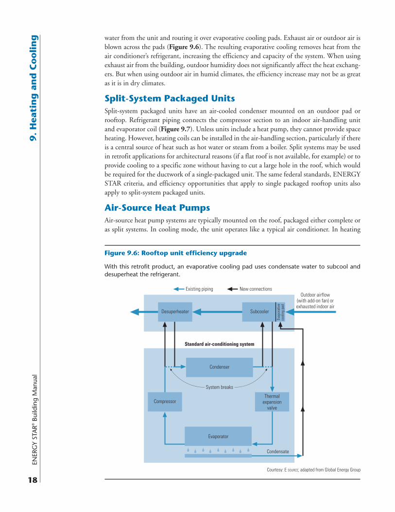
g water from the unit and routing it over evaporative cooling pads. Exhaust air or outdoor air is blown across the pads (Figure 9.6). The resulting evaporative cooling removes heat from the air conditioner’s refrigerant, increasing the efficiency and capacity of the system. When using exhaust air from the building, outdoor humidity does not significantly affect the heat exchang-ers. But when using outdoor air in humid climates, the efficiency increase may not be as great as it is in dry climates.
Split-System Packaged UnitsSplit-system packaged units have an air-cooled condenser mounted on an outdoor pad or rooftop. Refrigerant piping connects the compressor section to an indoor air-handling unit and evaporator coil (Figure 9.7). Unless units include a heat pump, they cannot provide space heating. However, heating coils can be installed in the air-handling section, particularly if there is a central source of heat such as hot water or steam from a boiler. Split systems may be used in retrofit applications for architectural reasons (if a flat roof is not available, for example) or to provide cooling to a specific zone without having to cut a large hole in the roof, which would be required for the ductwork of a single-packaged unit. The same federal standards, ENERGY STAR criteria, and efficiency opportunities that apply to single packaged rooftop units also apply to split-system packaged units.
Air-Source Heat PumpsAir-source heat pump systems are typically mounted on the roof, packaged either complete or as split systems. In cooling mode, the unit operates like a typical air conditioner. In heating
Figure 9.6: Rooftop unit efficiency upgrade
With this retrofit product, an evaporative cooling pad uses condensate water to subcool and desuperheat the refrigerant.
Existing piping New connections
Standard air-conditioning system
Outdoor airflow(with add-on fan) orexhausted indoor air
Evaporator
System breaks
Thermalexpansion
valve
Condensate
Desuperheater Subcooler
Evap
orat
ive
cool
ing
pad
Condenser
Compressor
Courtesy: E SOURCE; adapted from Global Energy Group
ENERG
Y STAR
® Building Manual
19
9. H
eating
and
Co
olin
g
mode, the cooling system operates in reverse, extracting heat from the outside air and using it to provide space heating. Air-source heat pump systems range in size from about 1.5 to 25 tons. High-efficiency air-source heat pumps have an EER as high as 11.5 and a COP for heat-ing as high as 3.6.
Air-source heat pumps offer an attractive alternative to rooftop units in cases when one needs to be replaced or a new unit is needed. Compared to packaged rooftop air conditioners that incorporate electric resistance heating coils, heat pumps offer improved year-round energy efficiency; compared to air conditioners that incorporate gas heating, heat pumps can offer cheaper operation where gas prices are high and electric rates are low.
In either case, most heat pumps are best suited to relatively warm climates, such as the south-eastern U.S. This is because when temperatures are low, a heat pump’s COP falls dramatically: A 7.5-ton rooftop heat pump that has a high-temperature COP of 3.0 can have a low-temperature COP of 2.0 or lower. And at very low temperatures, a heat pump can require supplemental heat, typically in the form of electric resistance—so effective heating efficiencies become even lower. However, dual-fuel heat pumps are available in areas where natural gas can be used as the supple-mental heating source.
Ground-Source, Closed-Loop Heat PumpsGround-source (geothermal) heat pumps evolved from the family of water-to-air heat pumps used in commercial buildings. These devices pump water or antifreeze through a buried coil of pipe to absorb heat from or reject heat to the ground, depending on whether heating or cool-ing is needed. Unlike the less common open-loop systems, the heat-exchange fluid stays within a closed loop and does not come into contact with the environment. Ground-source systems offer higher efficiencies than air-source heat pumps—they have EERs as high as 30 and COPs as high as 5. However, these units are also more expensive due to the network of pipes that must be buried. They are most appropriate in cold climates where the ground temperature is significantly warmer and less variable than the air temperature, and where natural gas for heat-ing is unavailable.
Figure 9.7: Location of split-system components
The compressor and condenser are in one self-contained outdoor unit and the evaporator and air handler are in another unit inside the building.
Indoor unitOutdoor unit
CompressorCondenser
Evaporator
Fan
Fan
Courtesy: E SOURCE; adapted from EPA
Air flow
Air flow
ENER
GY
STA
R® B
uild
ing
Man
ual
20
9. H
eati
ng
an
d C
oo
lin
g ENERGY STAR qualified ground-source closed-loop heat pumps must have at least an EER of 14.1 and a COP of 3.3. Both ENERGY STAR (www.energystar.gov/index.cfm?c=geo_heat.pr_geo_heat_pumps) and the Geothermal Heat Pump Consortium (www.geoexchange.org) offer more information on geothermal heat pump systems.
9.5 Additional Strategies
Depending on a building’s size, location, business use, and local utility rate structures, it may be worthwhile to investigate a number of additional technological strategies for saving energy and reducing costs.
Air-Side EconomizerThere are times when increasing outside air beyond ASHRAE Standard 62.1, “Ventilation for Acceptable Indoor Air Quality,” will lower cooling loads. Economizers can often use outdoor air to partially or totally cool a space. An economizer consists of local controls and dampers capable of delivering up to 100 percent outdoor air. Air-side economizers come in two types: dry-bulb and wet-bulb. A dry-bulb economizer is activated by outdoor air temperature—as temperature varies, the air damper modulates to bring in sufficient outdoor air to satisfy cool-ing needs. A wet-bulb economizer operates in the same manner, except it also monitors rela-tive humidity. However, wet-bulb economizers should only be used in appropriately humid climates because of their higher maintenance requirements—to maintain accuracy, they must be calibrated frequently.
Note that economizers offer excellent savings opportunities, but their operation is sensitive to temperature setpoints and the condition of system components. If operating incorrectly, they may not save energy. In some cases, if the dampers are stuck in the 100 percent outdoor air position all the time, for example, they could even waste energy. However, it is easy to avoid or minimize malfunctions. Using robust controls and a regular maintenance program can ensure that economizers function as intended. For guidance on proper economizer control, see the Eugene Water and Electric Board’s Tech Brief, “Outside Air Economizers: Making Them Work Right for You,” available at www.eweb.org/business/energy/energysmart/techbriefs.
Energy RecoveryHeat recovery is one of the most effective ways to optimize energy efficiency during building operations. Exhaust air from HVAC systems is a primary source of useful waste heat. Transfer-ring the energy from the exhaust air to the incoming outdoor air reduces the energy required to condition the incoming air.
Several heat-recovery technologies are available, including rotary heat wheels, plate-and-frame heat exchangers, runaround coils, and heat pipes—each suited to specific applications. Consult vendors and engineers to determine the best match for a given building. Depending on the application and technology type, these systems can recover 50 to 80 percent of the energy used to heat or cool incoming outdoor air.
Desiccant DehumidificationDesiccants dehumidify the air and can be regenerated through heating to drive out the absorbed moisture. The heat used for desiccant regeneration is generally derived from gas, steam, or waste heat from the building—and the cost of this heat is typically much lower than the cost of
gelectricity used for conventional dehumidification. Traditionally, desiccant systems have been targeted to humid climates or to applications that require tight control over humidity—like hospitals, museums, and supermarkets. But new hybrid air conditioning–desiccant systems are more efficient than previous desiccant technology. The higher efficiencies, coupled with changing building standards, are now making such systems appealing for applications where humidity control is still important but less critical, such as in schools, restaurants, and office buildings.
Changing building standards are making desiccant systems more appealing now for two rea-sons. First, to meet code, some buildings are admitting more outdoor air than their original design specified, leading to a larger need for humidity control. Second, where increasingly stringent energy-efficiency standards make the sensible (dry-air) cooling load lower than the humidity load, it is more challenging to handle humidity. For example, ASHRAE Standard 90.1, which is often adopted directly or indirectly in local building codes, has increased many efficiency requirements compared with the standards in place before the 1990s. Most of these changes have reduced the sensible cooling load (the portion of a building’s heat load unrelated to humidity) but not the latent cooling load (the portion of a building’s heat load contained in the moisture in the air). For instance, efficient lighting required by newer standards gives off less heat, but it does not reduce the moisture content of the air. A sensible load that is much lower than the latent load makes it more challenging for conventional air conditioners to con-dition the air properly without increasing energy use—desiccant systems offer another way to meet these challenges (see sidebar).
Night PrecoolingIn many climates, night temperatures are cool even when daytime temperatures exceed econo-mizer limits. Taking advantage of this resource, the air handler and economizer can flush the building with night air to cool down the building mass. The cool mass then acts as a heat sink the following day.
Setting controls for night precooling can save a significant amount of energy, depending on loca-tion. Studies indicate cost savings range from 5 percent in Phoenix, Arizona, to 18 percent in Den-ver, Colorado, for a typical office building. Night precooling also reduces peak demand. Simulation analyses show that precooling a 100,000-ft2 three-story building in Sacramento, California, would reduce energy use by 12.6 percent and cause a peak demand reduction of 31.3 percent.
CASE STUDY: Desiccants Save Energy While Dehumidifying
A November 2005 field study funded in part by the U.S. Department of Energy and con-ducted by the Georgia Tech Research Institute and Georgia State University showed that a hybrid air conditioner–desiccant system can dehumidify better than a conventional unit while saving energy. One elementary school in Atlanta, Georgia, was suffering from poor indoor air quality and occupant discomfort because the existing conventional packaged rooftop unit was not providing adequate dehumidification. The rooftop unit was replaced with a hybrid unit, which was able to maintain a relative humidity near 50 percent at an average thermostat setting 2.4° higher than the 70.4° Fahrenheit average setpoint the old system used. Based on energy simulations, this higher setpoint reduced cooling energy consumption by about 10 percent.
ENER
GY
STA
R® B
uild
ing
Man
ual
22
9. H
eati
ng
an
d C
oo
lin
g Cool StorageCool storage uses cheaper off-peak power to supply cooling and is generally only cost-effective in retrofits where the local utility offers a critical peak pricing program. The technology cools a storage medium while chiller operating cost is low, and then the medium is discharged when chiller operating cost is high. Cool storage media include water, ice and water, or water circu-lating around chemical modules that freeze and thaw. Ice systems and freeze-thaw systems take up less space than chilled-water storage because the freezing process can naturally store much more “cold” in a given volume. Most cool storage is custom built for a particular application, but one manufacturer, Ice Energy, produces packaged cool storage equipment.
Evaporative CoolingEvaporative cooling typically uses less than a quarter the energy of vapor-compression air-conditioning systems. In its basic form, air is blown over a wet surface. Heat in the air evapo-rates moisture from the surface, thereby lowering the temperature of the air. There are several types of evaporative coolers:
■ Direct. Also known as “swamp coolers,” these units evaporate moisture directly into the supply air stream, increasing its humidity. Although this effect may be desirable in dry climates, it is usually not so in humid ones.
■ Indirect. These units cool the building supply air through a heat exchanger with a separate air stream cooled by a direct evaporative cooler. The supply air does not come into contact with the wet surface, so no moisture is added.
■ Indirect-direct. Indirect-direct evaporative coolers, commonly called IDECs, first cool the supply air indirectly and then directly.
Although evaporative cooling systems are most effective in dry climates where the air has a large capacity to absorb evaporating water, they can also be used elsewhere to precool air to reduce the load on a mechanical refrigeration system. Mechanical refrigeration can also increase the evaporative cooling capacity by cooling the water used for evaporation.
9.6 Summary
Many opportunities exist for optimizing a building’s heating and cooling system efficiency. Load reductions achieved through other stages of the building upgrade process have likely made these opportunities more attractive than they were initially. When evaluating which heating and cooling upgrades to pursue, remember:
■ Determine the building’s heating and cooling loads.
■ Use current loads to calculate the proper capacity for equipment.
■ Consider the interactions among all system components.
■ Consider replacing old inefficient equipment with new high-efficiency equipment.
■ Evaluate alternative strategies for meeting heating and cooling loads.
■ Establish a regular maintenance program for all heating and cooling equipment.
ENERG
Y STAR
® Building Manual
23
9. H
eating
and
Co
olin
gAlthough heating and cooling improvements represent the final stage in the staged approach to building upgrades, they do not signal the end of the process. Building upgrades continue to provide the intended benefits throughout their useful life only through periodic recommis-sioning and further upgrades, as needed. An upgrade is not an endpoint but a step along a path of continuous improvement.
Bibliography
American Society of Heating, Refrigerating and Air-Conditioning Engineers Inc., “Energy Standard for Buildings Except Low-Rise Residential Buildings,” ANSI/ASHRAE/IESNA Standard 90.1-2004, www.ashrae.org.
Criscione, P., “Big Problems for Chiller Specifiers,” E Source Report, ER-04-11 (2004).
Criscione, P., “Look! Up in the Chiller Room! It’s a Screw Compressor, It’s a Centrifugal… No, It’s Turbocor! New Technology Flies into Town with Superbenefits,” E Source Report, ER-06-8 (2006).
Criscione, P., “Packaged Rooftop Air Conditioners: Product and Market Update,” E Source Report, ER-03-17 (2003).
Energy Design Resources, “Design Brief: Air Conditioning and Ventilation,” www .energydesignresources.com/resource/14 (accessed May 2007).
Fischer, J., Semco Inc., and Sand, J., “Field Test and Performance Verification: Integrated Active Desiccant Rooftop Hybrid System Installed in a School, Final Report: Phase 4a,” Oak Ridge National Laboratory, www.ornl.gov/sci/engineering_science_technology/cooling _heating_power/pdf/Timber_Ridge_Report_Final_Nov2005.pdf (2005).
Krepchin, I. and Lunneberg, T., “Variable-Speed Chillers Hit the Big Time,” E Source Report, ER-03-6 (2003).
Leinweber, S., “Utilities Target HVAC Maintenance to Shave Peak Load,” E Source Report, ER-02-7 (2002).
National Archives and Record Administration, “Code of Federal Regulations, Title 10, Chap-ter II,” Part 430.32, Residential Unitary Equipment and Furnaces; Part 431.77, Commercial Furnaces; Part 431.87, Commercial Boilers; and Part 431.97, Commercial Unitary Equip-ment, www.access.gpo.gov/nara/cfr/waisidx_07/10cfrv3_07.html (accessed May 2007).
Stein, J., “Low-Cost/No-Cost Efficiency Retrofits for Chiller Water Systems,” E Source Report, TU-97-9 (1997).
U.S. Department of Energy, Energy Information Administration, “Commercial Building Energy Use Survey” (2003), Table B7: Building Size, Floorspace and Table B35: Percent of Floorspace Cooled, Number of Buildings and Floorspace, www.eia.doe.gov/emeu/cbecs/cbecs2003/detailed_tables_2003/detailed_tables_2003.html (accessed May 2007).