UNIVERSIDADE FEDERAL DO RIO GRANDE DO SUL INSTITUTO DE INFORMÁTICA PROGRAMA DE PÓS-GRADUAÇÃO EM COMPUTAÇÃO CARLOS ARTHUR LANG LISBÔA Dealing with Radiation Induced Long Duration Transient Faults in Future Technologies Thesis presented in partial fulfillment of the requirements for the degree of Doctor of Philosophy (PhD) in Computer Science Prof. Dr. Luigi Carro Advisor Porto Alegre, June 2009.
Transcript
UNIVERSIDADE FEDERAL DO RIO GRANDE DO SUL
INSTITUTO DE INFORMÁTICA
PROGRAMA DE PÓS-GRADUAÇÃO EM COMPUTAÇÃO
CARLOS ARTHUR LANG LISBÔA
Dealing with Radiation Induced Long Duration Transient Faults
in Future Technologies
Thesis presented in partial fulfillment of the requirements for the degree of Doctor of Philosophy (PhD) in Computer Science
Prof. Dr. Luigi Carro Advisor
Porto Alegre, June 2009.
2
CIP – CATALOGAÇÃO NA PUBLICAÇÃO
UNIVERSIDADE FEDERAL DO RIO GRANDE DO SUL Reitor: Prof. Carlos Alexandre Netto Vice-Reitor: Prof. Rui Vicente Oppermann Pró-Reitor de Pós-Graduação: Prof. Aldo Bolten Lucion Diretor do Instituto de Informática: Prof. Flávio Rech Wagner Coordenador do PPGC: Prof. Álvaro Freitas Moreira Bibliotecária-Chefe do Instituto de Informática: Beatriz Regina Bastos Haro
Lisbôa, Carlos Arthur Lang
Dealing with Radiation Induced Long Duration Transient Faults in Future Technologies / Carlos Arthur Lang Lisbôa – Porto Alegre: Programa de Pós-Graduação em Computação, 2009.
<113> p.:il.
Tese (doutorado) – Universidade Federal do Rio Grande do Sul. Programa de Pós-Graduação em Computação. Porto Alegre, BR – RS, 2009. Supervisor: Luigi Carro.
1. Fault tolerance. 2. Radiation effects. 3. Low cost techniques. I. Carro, Luigi. II. Dealing with Radiation Induced Long Duration Transient Faults in Future Technologies.
3
ACKNOWLEDGMENTS
To my Father,
Arthur da Silva Lisbôa, for his many life-long examples in character: righteousness, goodness, endurance, and his dedication to and care of the family. Thank you, DAD! To my Wife, Partner, and Colleague since March 1973,
Maria Lúcia Blanck Lisbôa, for her love, care, partnership and support along the way. To my Supervisor,
Prof. Dr. Luigi Carro, for the many examples of creativity, scientific curiosity, and enthusiasm with research. And, last but not least, for accepting being my Supervisor and not having given up, in spite of all difficulties that I have imposed on him. To my
Friends and Colleagues at Instituto de Informática and Programa de Pós-Graduação em Ciência da Computação, for the incentive and effective support in every moment, and specially to my colleagues in courses of the Computer Architecture and Organization field, for allowing me to spend the required time in research, while they worked as my substitutes in lectures whenever I needed. To my
Co-Authors, for giving me the opportunity to work with them and for the many important contributions to our joint works.
4
AGRADECIMENTOS
A meu Pai,
Arthur da Silva Lisbôa, pelos exemplos de vida: retidão de caráter, bondade, cuidados com a família e perseverança. Obrigado, PAI! À minha Esposa, Companheira e Colega desde março de 1973,
Maria Lúcia Blanck Lisbôa, pelo amor, carinho, companhia e apoio ao longo deste caminho. A meu Orientador,
Prof. Dr. Luigi Carro, pelos exemplos de criatividade, curiosidade investigativa, e entusiasmo com a pesquisa. E, não menos importante, por haver aceito a pesada tarefa de me orientar e não haver desistido, apesar das dificuldades que impus a ele. A meus
Amigos e Colegas no Instituto de Informática e no Programa de Pós-Graduação em Ciência da Computação, pelo incentivo e apoio efetivo em todos os momentos, e em especial aos meus colegas das disciplinas da área de Arquitetura e Organização de Computadores, por terem me permitido dedicar o tempo necessário à pesquisa, me substituindo nos encargos docentes sempre que precisei. A meus
Co-Autores, pela oportunidade que me deram de trabalhar com eles e pelas importantes contribuições para nossos trabalhos conjuntos.
5
TABLE OF CONTENTS
LIST OF ABBREVIATIONS AND ACRONYMS ................................................ 8
LIST OF FIGURES ................................................................................................ 11
LIST OF TABLES .................................................................................................. 12
1.2 BASIC CONCEPTS AND RELATED WORK ............................................................................ 17 1.2.1 Radiation induced transients, SETs, SEUs, and Soft Errors ........................................... 17 1.2.2 Trends for soft errors in future technologies ..................................................................... 17 1.2.3 Multiple simultaneous transient faults ............................................................................... 18 1.2.4 Transient duration scaling vs. cycle times across technologies ........................................ 19
1.3 MAIN CONTRIBUTIONS ............................................................................................................ 19 1.3.1 Radiation Induced Long Duration Transients (LDTs) Effects ........................................ 19 1.3.2 Matrix Multiplication Algorithm Hardening .................................................................... 20 1.3.3 Use of Software Invariants for Runtime Detection of Transient Faults .......................... 20 1.3.4 Lockstep with Checkpoint and Rollback Improvement ................................................... 21 1.3.5 Use of Hamming Coding to Protect Combinational Logic ............................................... 21
2 LONG DURATION TRANSIENTS EFFECTS ............................................... 23
2.1 RADIATION INDUCED TRANSIENTS VS. DEVICE SPEED SCALING ............................... 23
2.2 CURRENT MITIGATION TECHNIQUES VS. LDTS ................................................................ 26 2.2.1 Software Based Techniques ................................................................................................. 27 2.2.2 Hardware Based Techniques .............................................................................................. 29
2.2.2.1 Time Redundancy .......................................................................................................... 29 2.2.2.2 Space Redundancy ......................................................................................................... 30 2.2.2.3 Mitigation Techniques Based on Watchdogs, Checkers and IPs.................................... 31
3.1 PROBLEM DEFINITION ............................................................................................................. 38
3.2 RELATED AND PREVIOUS WORK .......................................................................................... 39
3.3 PROPOSED TECHNIQUE ........................................................................................................... 40 3.3.1 Background and Evolution of the Proposed Technique ................................................... 40
3.3.1.1 The starting point: fingerprinting and Freivalds’ technique ........................................... 40 3.3.1.2 Improving Freivalds’ technique ..................................................................................... 41
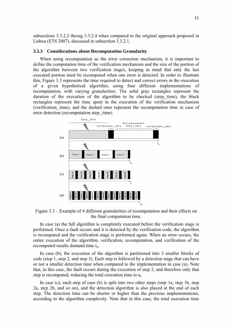
3.3.2 Minimizing the Recomputation Time when an Error Occurs ......................................... 44 3.3.2.1 Verification only at completion of product matrix calculation....................................... 44 3.3.2.2 Verification line by line .................................................................................................. 45 3.3.2.3 Erroneous element detection and single element recomputation after multiplication
completion ...................................................................................................................... 47 3.3.2.4 Minimizing the single element recomputation cost ........................................................ 49 3.3.2.5 Comparative analysis of results ...................................................................................... 50
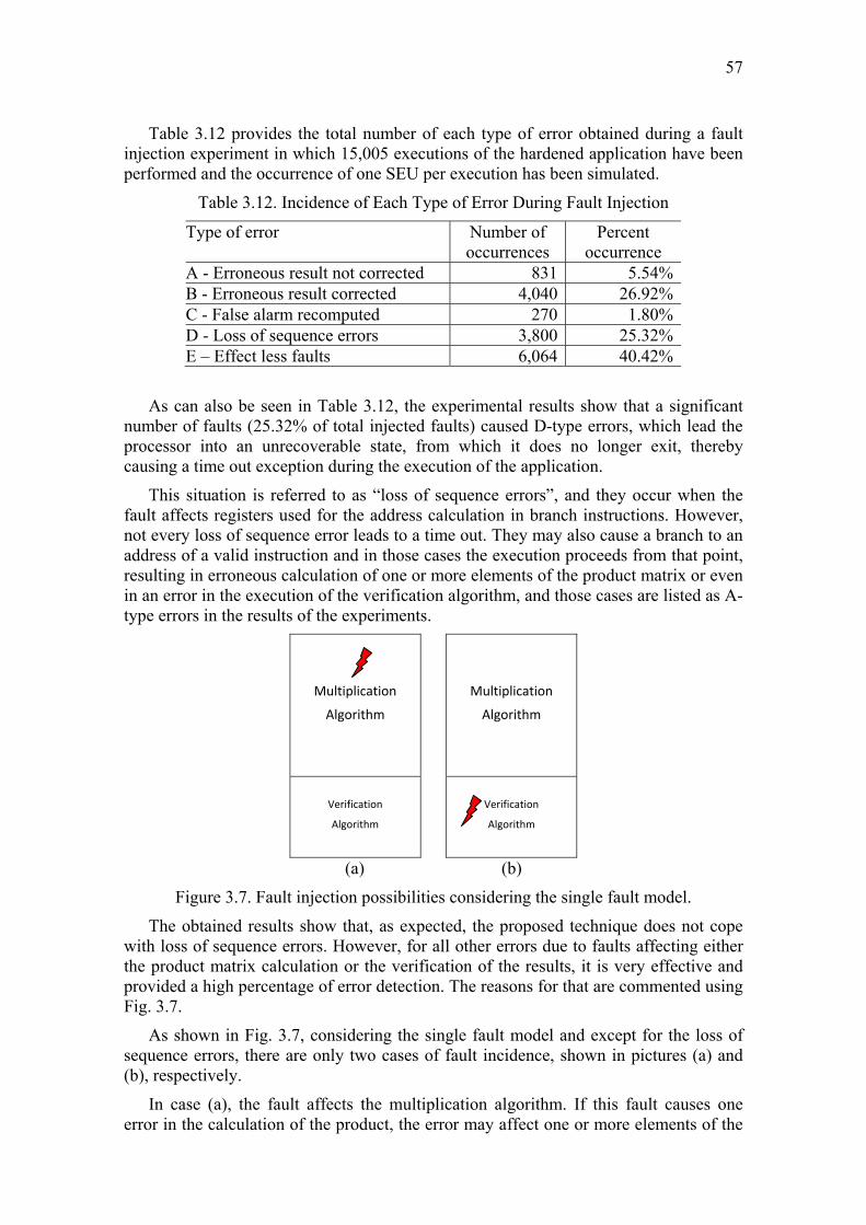
3.3.3 Considerations about Recomputation Granularity ........................................................... 51 3.3.4 Validation by Fault Injection .............................................................................................. 55
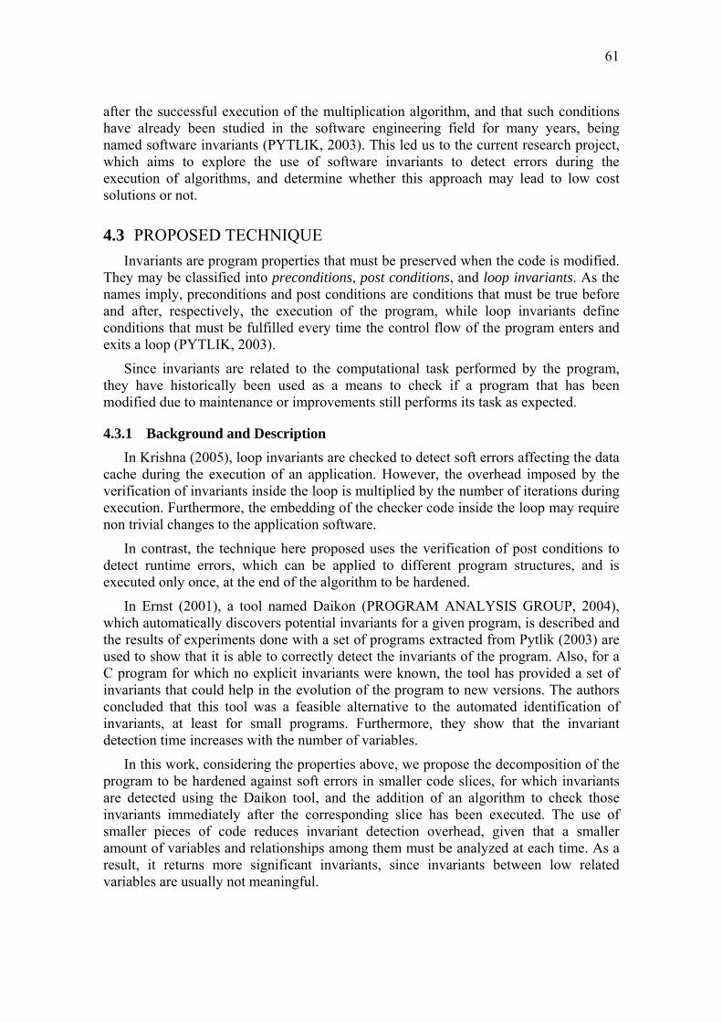
4.3.2 Application to a Sample Program ...................................................................................... 63 4.3.3 Experimental Results and Analysis .................................................................................... 64
5 IMPROVING LOCKSTEP WITH CHECKPOINT AND ROLLBACK ...... 67
5.1 PROBLEM DEFINITION ............................................................................................................. 67
5.2 RELATED WORK AND PREVIOUS IMPLEMENTATION ..................................................... 68 5.2.1 Related Work ....................................................................................................................... 68 5.2.2 Previous Implementation of Lockstep with Checkpoint and Rollback ........................... 69
5.3 IMPROVING THE PERFORMANCE BY MINIMIZING CHECKPOINT TIME ...................... 79 5.3.1 Background and Description .............................................................................................. 79 5.3.2 Experimental Results and Analysis .................................................................................... 80
6 HAMMING CODING TO PROTECT COMBINATIONAL LOGIC ........... 83
6.1 PROBLEM DEFINITION ............................................................................................................. 83
7
6.2 RELATED AND PREVIOUS WORK .......................................................................................... 84
6.3.1.1 The Advantages of Hamming Code ............................................................................... 86 6.3.1.2 Extending the Use of Hamming Code to Combinational Logic Hardening ................... 87 6.3.1.3 Analysis of Combinational Hamming Operation for a Sample Circuit .......................... 88
6.3.2 Comparing Combinational Hamming to TMR ................................................................. 89 6.3.3 Application of Combinational Hamming to Arithmetic Circuits .................................... 90
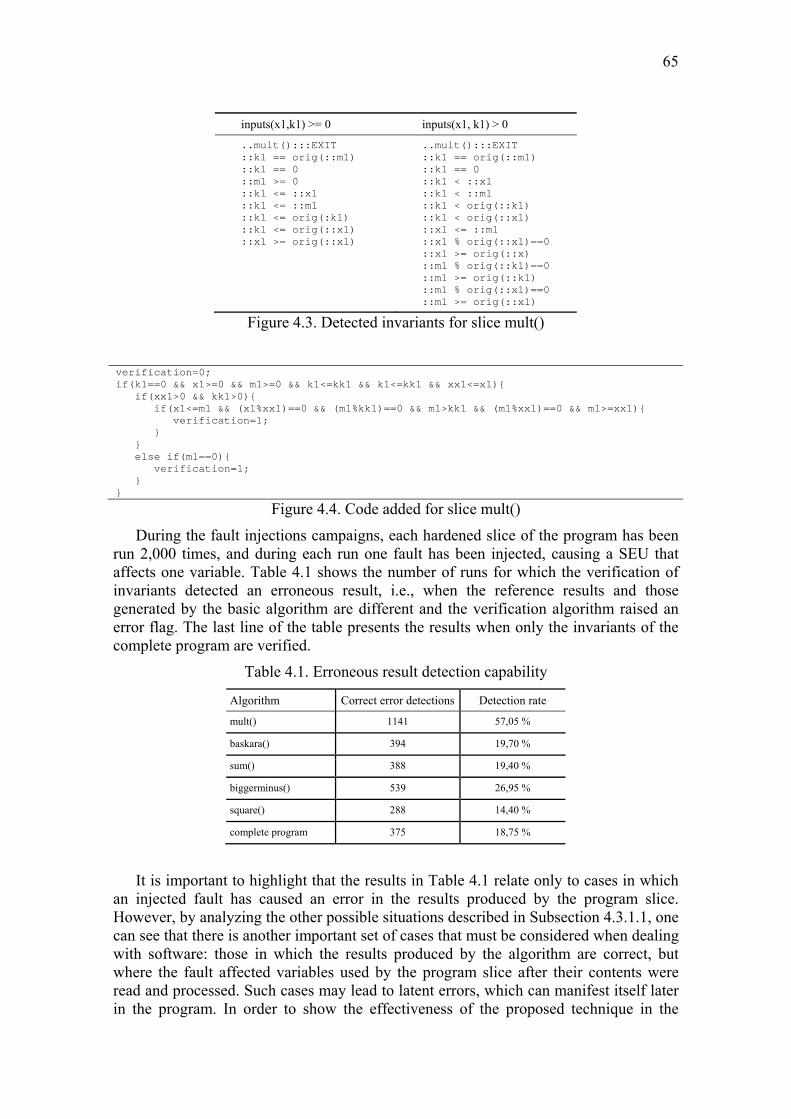
6.3.4 Application of Combinational Hamming to a Set of Combinational Circuits of the MCNC Benchmark .............................................................................................................. 94
7 CONCLUSIONS AND FUTURE WORKS ....................................................... 99
7.1 MAIN CONCLUSIONS ................................................................................................................ 99
7.2 SUMMARY OF CONTRIBUTIONS.......................................................................................... 100 7.2.1 Long Duration Transients Effects .................................................................................... 100 7.2.2 Matrix Multiplication Hardening ..................................................................................... 100 7.2.3 Using Invariants for Runtime Detection of Faults .......................................................... 100 7.2.4 Improving Lockstep with Checkpoint and Rollback ...................................................... 101 7.2.5 Hamming Coding to Protect Combinational Logic ......................................................... 101
7.3 PROPOSED RESEARCH TOPICS FOR FUTURE WORKS .................................................... 101 7.3.1 Use of Software Invariants for Runtime Error Detection .............................................. 102 7.3.2 Lockstep with Checkpoint and Rollback ......................................................................... 102 7.3.3 Combinational Hamming .................................................................................................. 102
Figure 1.1: One particle, multiple effects ...................................................................... 18 Figure 2.1: Transient pulse width scaling across technologies ..................................... 23 Figure 2.2: Transient pulse width scaling across technologies ..................................... 24 Figure 2.3: Transient width vs. clock cycles ................................................................. 25 Figure 2.4: SET pulse width vs. cycle time scaling ...................................................... 26 Figure 2.5: Temporal redundancy technique ................................................................. 30 Figure 2.6: Long duration transient effect ..................................................................... 31 Figure 3.1: Fingerprinting - generic scheme ................................................................. 41 Figure 3.2: Operations used in the verification of the product ...................................... 43 Figure 3.3: Example of 4 different granularities of recomputation and their effects on the final computation time ......................................................... 51 Figure 3.4: Execution time costs according to the levels of granularity (1 to 10 steps)
and verification time (verificationi_time) varying from 10% to 100% of the stepi_time ............................................................................... 53 Figure 3.5: Multiple errors and the masked effect when dealing with levels of
granularity ................................................................................................... 53 Figure 3.6: Block diagram of the ASTERICS platform ................................................ 55 Figure 3.7: Fault injection possibilities considering the single fault model .................. 57 Figure 4.1: Program hardening experiments flow ......................................................... 62 Figure 4.2: Test program split into slices ...................................................................... 64 Figure 4.3: Detected invariants for slice mult() ............................................................. 65 Figure 4.4: Code added for slice mult() ......................................................................... 65 Figure 5.1: Flow chart of rollback recovery using checkpoint ...................................... 70 Figure 5.2: Example of execution of rollback recovery using checkpoint .................... 70 Figure 5.3: Architecture of the synchronized lockstep with rollback ............................ 74 Figure 5.4: Architecture modified to include the WHT ................................................ 80 Figure 5.5: Average cycles per write vs. matrix size comparison ................................. 81 Figure 6.1: (a) Typical Hamming code application, with fixed size code Word. (b) Ty-
pical combinational circuit, with different number of inputs and outputs .. 86 Figure 6.2: Hamming code application to a ripple carry adder circuit .......................... 88 Figure 6.3: Hamming code word format for the ripple carry adder circuit shown in Fig. 6.2 ........................................................................................ 88 Figure 6.4: m-input, n-output TMR implementation ..................................................... 89 Figure 6.5: Multiplier implementation using combinational Hamming ........................ 91
12
LIST OF TABLES
Table 1.1: Propagation Delay vs. Transient Widths across Technologies (ps) ............. 20 Table 2.1: Predicted Transient Widths (ps) .................................................................... 24 Table 2.2: Simulated Propagation Delay Scaling Accross Technologies (ps) .............. 25 Table 3.1: Matrix multiplication computational cost scaling with n .............................. 39 Table 3.2: Computational cost scaling with n ............................................................... 44 Table 3.3: Number of operations for verification after completion .............................. 45 Table 3.4: Computational cost scaling with n for verification after completion ............ 45 Table 3.5: Number of operations for verification line by line ........................................ 46 Table 3.6: Computational cost scaling with n for verification line by line .................... 46 Table 3.7: Number of operations for erroneous element detection ................................ 49 Table 3.8: Computational cost scaling with n for erroneous element correction ........... 49 Table 3.9: Minimal computational cost scaling with n
for erroneous element correction ................................................................... 50 Table 3.10: Comparative analysis - total cost when one error occurs ............................ 50 Table 3.11: Comparative analysis - cost of recomputation when one error occurs ........ 50 Table 3.12: Incidence of Each Type of Error During Fault Injection ............................ 57 Table 4.1: Erroneous result detection capability ............................................................ 65 Table 4.2: Fault detection capability .............................................................................. 66 Table 4.3: Performance overhead ................................................................................... 66 Table 5.1: Sensitive bits for IP ....................................................................................... 76 Table 5.2: Results of fault injection on the processors ................................................... 78 Table 5.3: Data segment size break-even point for use of WHT ................................... 82 Table 6.1: Circuits used in the experiments ................................................................... 91 Table 6.2: Areas of the circuits hardened by the proposed technique (μm2) .................. 92 Table 6.3: Power of the circuits hardened by the proposed technique (mW) ................ 92 Table 6.4: Delays of the circuits hardened by the proposed technique (ns) ................... 92 Table 6.5: Proposed technique vs. TMR: areas comparison (μm2) ................................ 93 Table 6.6: Proposed technique vs. TMR: power comparison (mW) .............................. 93 Table 6.7: Proposed technique vs. TMR: delay comparison (ns) ................................... 95 Table 6.8: Circuits from the MCNC benchmark used in the experiments ..................... 95 Table 6.9: Areas of the circuits protected using the proposed technique (μm2) ............. 96 Table 6.10: Power of the circuits protected using the proposed technique (mW).......... 96 Table 6.11: Delay of the circuits protected using the proposed technique (ns) .............. 97 Table 6.12: Proposed technique vs. TMR: areas comparison (μm2) .............................. 97 Table 6.13: Proposed technique vs. TMR: power comparison (mW) ............................ 98 Table 6.14: Proposed technique vs. TMR: delays comparison (ns) ............................... 98 Table 6.15: Comparison between Combinational Hamming and
the technique proposed in (Almukhaizim, 2003) ........................................ 99
13
ABSTRACT
As the technology evolves, faster and smaller devices are available for manufacturing circuits that, while more efficient, are more sensitive to the effects of radiation. The high transistor density, reducing the distance between neighbor devices, makes possible the occurrence of multiple upsets caused by a single particle hit. The achievable high speed, reducing the clock cycles of circuits, leads to transient pulses lasting longer than one cycle. All those facts preclude the use of several existing soft error mitigation techniques based on temporal redundancy, and require the development of innovative fault tolerant techniques to cope with this challenging new scenario.
This thesis starts with the analysis of the transient width scaling across technologies, a fact that supports the prediction that long duration transients (LDTs) will affect systems manufactured using future technologies, and shows that several existing mitigation techniques based on temporal redundancy will not be able to cope with LDTs, due to the huge performance overhead that they would impose. At the same time, space redundancy based techniques, despite being able to deal with LDTs, still impose very high area and power penalties, making them inadequate for use in some application areas, such as portable and embedded systems. As an alternative to face those challenges imposed to designers by future technologies, the development of low overhead mitigation techniques, working at different abstraction levels, is proposed. Examples of new low cost techniques working at the circuit, algorithm, and architecture levels are presented and evaluated.
Working at the algorithm level, a low cost verification algorithm for matrix multiplication is proposed and evaluated, showing that it provides a good solution for this specific problem, with dramatic reduction in the cost of recomputation when an error in one of the product matrix elements is detected. In order to generalize this idea, the use of software invariants to detect soft errors at runtime is suggested as a low cost technique, and shown to provide high fault detection capability, being a good candidate for use in a complementary fashion in the development of software tolerant to transient faults. As an example of architecture level technique, the improvement of the classic lockstep with checkpoint and rollback technique is proposed and evaluated, showing significant reduction in the number of write operations required for checkpoints. Finally, as an example of low cost space redundancy technique at circuit level, the use of Hamming coding to protect combinational logic, an open issue in the design of systems using future technologies, is proposed and evaluated through its application to a set of arithmetic and benchmark circuits.
Lidando com Falhas Transitórias de Longa Duração Provocadas por Radiação em Tecnologias Futuras
RESUMO
Com a evolução da tecnologia, dispositivos menores e mais rápidos ficam disponíveis para a fabricação de circuitos que, embora sejam mais eficientes, são mais sensíveis aos efeitos da radiação. A alta densidade, ao reduzir a distância entre dispositivos vizinhos, torna possível a ocorrência de múltiplas perturbações como resultado da colisão de uma única partícula. A alta velocidade, ao reduzir os ciclos de relógio dos circuitos, faz com que os pulsos transientes durem mais do que um ciclo. Todos estes fatos impedem o uso de diversas técnicas de mitigação existentes, baseadas em redundância temporal, e tornam necessário o desenvolvimento de técnicas inovadoras para fazer frente a este novo e desafiador cenário.
Esta tese inicia com a análise da evolução da duração de pulsos transitórios nas diferentes tecnologias que dá suporte à previsão de que transitórios de longa duração (TLDs) irão afetar sistemas fabricados usando tecnologias futuras e mostra que diversas técnicas de mitigação baseadas em redundância temporal existentes não serão capazes de lidar com os TLDs devido à enorme sobrecarga que elas imporiam ao desempenho. Ao mesmo tempo, as técnicas baseadas em redundância temporal, embora sejam capazes de lidar com TLDs, ainda impõem penalidades muito elevadas em termos de área e energia, o que as torna inadequadas para uso em algumas áreas de aplicação, como as de sistemas portáteis e embarcados. Como uma alternativa para enfrentar estes desafios impostos aos projetistas pelas tecnologias futuras, é proposto o desenvolvimento de técnicas de mitigação com baixa sobrecarga, atuando em níveis de abstração distintos. Exemplos de novas técnicas de baixo custo atuando nos níveis de circuito, algoritmo e arquitetura são apresentados e avaliados.
Atuando em nível de algoritmo, uma alternativa de baixo custo para verificação de multiplicação de matrizes é proposta e avaliada, mostrando-se que ela oferece uma boa solução para este problema específico, com uma enorme redução no custo de recomputação quando um erro em um elemento da matriz produto é detectado. Para generalizar esta idéia, o uso de invariantes de software na detecção de erros transitórios durante a execução é sugerido como outra técnica de baixo custo, e é mostrado que esta oferece alta capacidade de detecção de falhas, sendo, portanto, uma boa candidata para uso de maneira complementar com outras técnicas no desenvolvimento de software tolerante a falhas transitórias. Como exemplo de uma técnica em nível de arquitetura, é proposta e avaliada uma melhoria da clássica técnica de lockstep com checkpoint e rollback, mostrando uma redução significativa no número de operações de escrita necessárias para um checkpoint. Finalmente, como um exemplo de técnica de baixo custo baseada em redundância espacial, é proposto e avaliado o uso de código de Hamming na proteção de lógica combinacional, um problema ainda em aberto no projeto de sistemas usando tecnologias futuras.
Palavras-Chave: tolerância a falhas, efeitos de radiação, técnicas de baixo custo.
15
1 INTRODUCTION
This work proposes the development of new low cost fault tolerance techniques, working at different abstraction levels, as the preferred alternative to deal with faults caused by long duration transients that will affect CMOS devices to be manufactured in future technologies. The analysis of the effects of such long duration transients and the reasons why several current mitigation techniques will fail in this new scenario are presented, and four techniques that deal with the problem at different abstraction levels are proposed, always pursuing low cost requirements.
1.1 MOTIVATIONS The evolution of semiconductor technology in recent years, while continuously
providing new devices with unmatched size, speed, and power consumption characteristics, has brought along increasing concerns about the reliability of systems to be designed using those devices. While CMOS technology keeps evolving according to Moore’s law, thereby approaching the physical limits imposed by the availability of only a few atoms to form the device’s channel (KIM et al., 2003) (HOMPSON et al., 2005), the development of alternative technologies, able to take digital systems beyond those limits, became a huge challenge to be faced by scientists.
But even the most promising alternative technologies devised so far bring along the same undesirable characteristic: devices manufactured using them are more prone to manufacturing defects and transient errors than nanoscale CMOS, making the reliability goal even more difficult to be reached.
The decreasing reliability of CMOS devices in new technologies is a consequence of several different problems arising from the physical characteristics of those devices:
• The lower power consumption and operating temperature limits imposed by embedded and portable systems requirements lead to the use of lower operating voltages, which in turn imply smaller critical charges, making the devices more susceptible to radiation induced transient pulses, since even particles with relatively small energy can upset those devices (VELAZCO, 2007). As a consequence, the occurrence of Single Event Transients (SETs) and Single Event Upsets (SEUs) has been increasing in recent years, and became a concern not only for systems targeting space or avionics applications, but also for those designed for critical missions meant to be used at sea level (HEIJMEN, 2002). According to the International Technology Roadmap for Semiconductors 2008 Update, “Below 65nm, single-event upsets (soft errors) impact field-level product reliability, not only for embedded memories, but for logic and latches as well.” (INTERNATIONAL..., 2008). Furthermore, while several error detection and correction (EDAC) techniques have been proposed and are in current use to
16
protect memory devices against those effects, thereby stabilizing the soft error rate (SER) across technology nodes, the protection of combinational logic against SETs and SEUs is still an open issue.
• Smaller device dimensions allow the construction of circuits with higher densities, in which the distance between neighbor devices is reduced between consecutive technology nodes. Such very small distances allow that a single particle hitting the silicon affects two or more devices at the same time, thereby causing multiple simultaneous faults, a possibility that was not considered until recently, and therefore is not mitigated by currently existing fault tolerance techniques (ROSSI et al., 2005), (ANGHEL, 2007). This multiple simultaneous faults scenario, in turn, can lead to catastrophic consequences when well established and proven techniques in use under the single fault model are used with future technologies. Triple modular redundancy (TMR), for instance, is not able to properly select the correct result when two of the voter inputs are equally erroneous. Similarly, the duplication with comparison (DWC) approach becomes useless to detect errors in a scenario where both duplicated modules can generate equally erroneous outputs.
• These faster new devices allow designing circuits with shorter cycle times, but unfortunately, the duration of radiation induced transient pulses does not scale at the same pace of the cycle times (DODD, 2004), (FERLET-CAVROIS, 2006), leading to a situation in which transient pulses may become longer than the cycle time of the circuits. Current soft error mitigation techniques either are not able to cope with this new scenario due the high performance overheads that they would impose to cope with such long duration transients, or do impose very high area and power consumption overheads, which will require the development of new low cost system level mitigation techniques (LISBOA, ETS 2007).
• Besides all those undesirable effects over reliable system operation caused by CMOS technology evolution, the manufacturing of digital systems is also affected by increasing defect rates due to process variations, higher complexity for manufacturing test due to increased components density in the circuits, and other related problems (AGARWAL et al., 2005).
To cope with this new scenario, the design of reliable portable and embedded systems will also have to evolve, through the development of innovative solutions to mitigate soft errors using the smallest possible overhead. Given the extreme unreliability of components to be manufactured not only in new CMOS technology nodes, but also in the alternative technologies proposed so far, dealing with this problem at the component level will become too expensive. The prediction of long duration transients, lasting more than one or even several cycles of operation of the circuits, makes the mitigation at low level (technology or component levels), using temporal redundancy techniques, also unfeasible, due to the enormous overhead in performance that this would mean.
Therefore, a natural path to be followed in the search for the required new set of techniques is then to raise the abstraction level and work at circuit, architecture, algorithm and system levels, in order to develop techniques able to detect and correct errors with low design and fabrication costs.
While keeping low area, power and performance overheads is a mandatory characteristic of candidate techniques, it is also important that their deployment be made without significant changes in the way system developers explore the parallelism or
17
write their code, for example. In other words, any new technique must gracefully fit into the current system design flow, allowing for their seamless introduction in the system development process, without any dramatic change to the established levels of design abstraction.
1.2 BASIC CONCEPTS AND RELATED WORK In this section, we introduce the main technical terms used in the text, and discuss
the reasons why radiation induced transients will become a major cause of errors during the operation of circuits manufactured using future technologies.
1.2.1 Radiation induced transients, SETs, SEUs, and Soft Errors This work focuses on the effects of the incidence of radiation particles during the
normal operation of digital circuits that have nor defects nor permanent errors. Such effects are due to the deposition of charge caused by the impact of the particle on silicon, which may switch the logical state of nodes. However, after the deposited charge dissipates, the effects of these events usually disappear. For this reason, these effects are called Single Event Transients (SETs), and the faults caused by SETs are called transient faults (HEIJMEN, 2002).
If the particle’s linear energy transfer (LET) is high enough to generate charge above the critical charge of the node, the SET is able to switch the logical state of the node, and the erroneous value can be propagated trough the logic to the output of the network and eventually reach a memory element. If this happens during the latching window of the memory element, this incorrect information can be stored, resulting in a Single Event Upset (SEU), which is considered a Soft Error, because the upset memory element remains operational and able to eventually store new information when a write operation on that same element is performed.
A SET can be masked, either logically, electrically or by the lack of a latching window, in which case it generates no error at all. However, in order to cope with errors that may occur when the SET is not masked, a proper detection and mitigation technique must be included during the design phase of the circuit, to ensure SET tolerant operation.
The two main sources of radiation that may affect the circuits are alpha particles originated in the chip itself by the decay of impurities contained in materials used for packaging or in the manufacturing process (e.g., lead and boron), and neutrons in cosmic rays, which may collide with a silicon nucleus and cause ionization with high linear energy transfer (LET) (KARNIK, 2004).
While the radiation effects due to processes and materials can be mitigated through elimination of their causes, and this is a continuous subject of research by the manufacturing community, those due to cosmic rays cannot be avoided without the use of unpractical and expensive shielding mechanisms (HEIJMEN, 2002), and therefore must be considered in the design of general purpose circuits.
1.2.2 Trends for soft errors in future technologies The well-established SET fault model is based on a single particle hitting a
sensitive node in silicon, and generating a transient pulse which changes the state of the affected node (DIEHL, 1983). According to Baumann (2001), the three primary sources
18
for the induction of soft errors in semiconductor devices are alpha particles, high-energy cosmic neutrons, and neutron-induced boron fission.
The major sources of alpha particles are materials used during the manufacturing process and packaging materials, which allows the reduction of their influence through modifications in the processes and replacement of packaging materials (HEIJMEN, 2002).
Historically, the incidence of soft errors in combinational logic has been considered less problematic than that in memory elements. Therefore, several soft error detection and correction (EDAC) techniques have been proposed and used to detect and recover from SEUs in memory. More recently, Baumann (2005) has shown that, while the memory soft error rate was almost stable across technologies, the soft error rate for combinational logic has been growing from one technology node to the other. This fact points to the need for increased efforts towards the development of design techniques able to cope with soft errors in combinational logic in future technologies, as has been recently recognized by the industry experts, which included it as one of the crosscutting design challenges, under the reliability chapter (INTERNATIONAL..., 2008).
1.2.3 Multiple simultaneous transient faults While the hypothesis of multiple simultaneous faults has been considered
negligible for a long time, an industry report by Heijmen (2002) already warned that it should no longer be neglected for circuits manufactured using technologies of 0.13 μm and beyond.
This growing concern about multiple transient faults is not due to any change in the nature of radiation phenomena. Rather, it naturally stems from the continuous evolution of the semiconductor technology, which provides ever smaller devices and higher densities, thereby reducing the distance between neighbor nodes in a circuit and increasing the possibility of more than one transient fault occurring at the same time.
Those multiple simultaneous faults are still due to a single particle hitting the silicon, in which case secondary particles can be emitted in several directions, as illustrated in Figure 1.1 (ROSSI, 2005).
Figure 1.1. One particle, multiple effects (ROSSI, 2005)
What has changed is that, since the devices are now closer to each other, those secondary particles may eventually affect two different nodes of a circuit, generating two simultaneous effects (NEUBERGER, 2003).
Moreover, after experimentally confirming that two simultaneous upsets affecting adjacent nodes can occur, Rossi (2005) has shown that the occurrence of bi-directional errors, i.e., two simultaneous complementary bit flips, will be possible, precluding the use of error detection codes designed to detect only unidirectional simultaneous errors.
One year later, Ferlet-Cavrois (2006) presented a detailed study on the charge collection mechanisms in SOI and bulk devices exposed to heavy radiation, using
19
different technologies, from 0.25 μm to 70 nm. For bulk devices, that analysis shows that the shape and duration of transient pulses present significant variations, depending on the fabrication details, on the technology itself, and on the location in the device that was hit by the particle. Moreover, the comparison of the behavior of the same device exposed to different radiation sources has shown that some particles do not have enough LET to induce SEUs or SETs by direct ionization. However, those particles generate secondary ones, with much higher LETs, that can be emitted in all directions. Once again, the hypothesis of multiple transients generated by a single particle hit has been confirmed.
This conclusion, alone, has strong negative impact on many current mitigation techniques based on the single fault hypothesis, such as the classic triple modular redundancy - TMR (JOHNSON, 1994).
1.2.4 Transient duration scaling vs. cycle times across technologies Besides higher densities, the availability of faster devices is another feature of
future technologies that brings along strong concerns to the error tolerance community, because it has been predicted that, for those technologies, even particles with modest linear energy transfer (LET) values will produce transients lasting longer than the predicted cycle time of circuits (DODD, 2004), (FERLET-CAVROIS, 2006). The negative impact of the effects of such long duration transients (LDTs) on the overhead imposed by currently used temporal redundancy based error mitigation techniques has been first presented in Lisboa (ETS 2007), and is a key concept behind our thesis work. For this reason, this topic is further detailed in Chapter 2.
1.3 MAIN CONTRIBUTIONS The main novelty in this work is the finding that currently used temporal
redundancy based techniques will not be able to mitigate errors caused by long duration transients affecting devices manufactured using future technologies at a reasonable cost. Besides that, this work proposes to deal with the problem working at different abstraction levels, with each solution complementing the protection provided at other levels, aiming the full protection of a given system. In order to show some alternatives that may be part of a complete solution to achieve that goal, four low cost techniques that can be implemented at algorithm, system or circuit level, are suggested and analysed.
1.3.1 Radiation Induced Long Duration Transients (LDTs) Effects
The first significant step in this research work was the analysis of the effects of what has been named “long duration transients” (LDTs) on soft errors mitigation techniques. This forecast was embedded in published works concerning the effects of radiation on semiconductor devices in different technology nodes (DODD, 2004), (FERLET-CAVROIS, 2006), and has been confronted with the predicted cycle times for inverters chains with different lengths, obtained through simulation, in Lisboa (ETS 2007).
When contrasting the evolution of the width of radiation induced transient pulses across technologies with that of the cycle times of circuits, one could see that, while the cycle times decrease in a quite linear form, there is no clear scaling trend for the width of the transient pulses. Furthermore, for technologies beyond the 130 nm node, it has been shown that the duration of transient pulses will exceed the predicted cycle time of circuits (LISBOA, ETS 2007). Table 1.1 illustrates this fact using data for a 10-inverter
20
chain. The transient width figures in Table 1.1 have been extracted from Dodd (2004) and Ferlet-Cavrois (2006), while those for propagation delays have been estimated through simulation, using parameters from the Predictive Technology Model web site (ARIZONA STATE UNIVERSITY, 2007). A detailed anaylsis is shown in Chapter 2.
Table 1.1. Propagation Delay vs. Transient Widths across Technologies (ps)
The analysis of the behavior of temporal redundancy based techniques in this new scenario has shown that they cannot cope with LDTs, due to the unbearable performance overhead that they would impose. In contrast, space redundancy based techniques, that could cope with LDTs, impose area and power overheads that are not suited to the requirements of several applications areas, such as the portable and embedded systems arenas. From this analysis, detailed in Chapter 2, the need to work at higher abstraction levels to face this new scenario has been defined, and the search for low cost techniques to detect and correct errors caused by LDTs at circuit, algorithm and system levels has started.
1.3.2 Matrix Multiplication Algorithm Hardening In order to show how to deal with the problem at algorithm level, the matrix
multiplication algorithm has been chosen as a test case. While this operation is widely used in several application fields, the error detection and correction of erroneous elements of the product matrix sometimes is a bottleneck that may lead to missed deadlines (in real time systems, for example). Considering that the multiplication of n×n matrices requires O(n3) operations, including additions, multiplications and comparisons of scalar values, the cost of duplication with comparison or triple modular redundancy to detect or correct errors in the product matrix becomes very high.
Departing from the study of a classic error detection technique proposed in the seventies (FREIVALDS, 1979), which is able to detect errors in one element of the product matrix with a probability of at least ½, a new technique that provides deterministic error detection has been developed and shown to be much faster than the recomputation of the whole product matrix and comparison of the results (LISBOA, ETS 2007). In cooperation with the TIMA Laboratoire, in Grenoble, France, a microcontroller running the hardened algorithm has been submitted to radiation campaigns, in order to confirm its effectiveness. Later, the technique has been also extended for use with non-square matrices and vectors. This contribution is detailed in Chapter 3.
1.3.3 Use of Software Invariants for Runtime Detection of Transient Faults In the search for a deterministic approach for error detection in matrix multiplication
algorithms, one reached the conclusion that the test of a single condition was enough to detect errors affecting one element of the product matrix. In other words, a relationship between the results generated by the algorithm, which holds whenever the execution ended correctly, has been found for that algorithm.
21
Such conditions have been in use for a long time in the software engineering field, and are known as software invariants. However, most of the works using software invariants are related to the software life cycle, and intended to ensure that a program worked properly after any modifications had been made.
In this work, the run-time verification of software invariants is proposed as a low cost mechanism to detect radiation induced faults during the execution of an algorithm, and is shown to be an effective fault detection mechanism that should be further explored. Chapter 4 describes in more details the experiments performed using software invariants to detect soft errors and faults, as well as the achieved results.
1.3.4 Lockstep with Checkpoint and Rollback Improvement The lockstep technique, combined with the use of checkpoints and rollback, is not a
new subject. However, until recently, it was almost neglected because its application to commercial off-the-shelf (COTS) processors was not practical. Nowadays, the commercial availability of FPGAs with multiple built-in hardwired processors brings the lockstep technique back as a good alternative to harden FPGA based systems against soft errors.
Based on this scenario, the CAD Group of Dipartimento di Automatica e Informatica of Politecnico di Torino, in Italy, has started a project aiming to implement fault tolerant FPGA based systems using lockstep combined with checkpoint and rollback.
As part of its PhD studies, the author has worked in cooperation with the CAD Group during four months, in 2008. While in Torino, the improvement of an existing implementation of the technique, through the use of an additional IP inside the FPGA that stores the information related to a set of memory write operations for later use during checkpoints has been proposed and implemented.
The proposed improvement, together with the experiments that have been conducted in order to evaluate the effects of its application on the system performance, is described in Chapter 5 as an example of architecture level technique that could cope with radiation effects in future technologies.
1.3.5 Use of Hamming Coding to Protect Combinational Logic
Introduced in the fifties, in the last century, Hamming Coding is a powerful tool used for error detection and correction in storage elements and data communications applications. In those applications, however, the number of data bits written/transmitted or read/received is always the same.
In contrast, in combinational circuits the number of inputs is usually different from the number of outputs, a feature that, so far, has precluded the direct application of Hamming coding in the hardening of combinational logic.
In this work, an innovative approach to the use of Hamming coding in the protection of combinational circuits against transient faults of any kind is proposed, and its cost is evaluated and compared to that of the classic triple modular redundancy technique, showing that Combinational Hamming is a good candidate technique for this role. The proposed technique uses space redundancy, and is an example of how to reduce the area and power overheads imposed by classic alternatives.
The description of the technique and the experimental results achieved with a set of combinational circuits are included in Chapter 6, as an example of circuit level
22
hardening technique that can complement the existing sequential logic hardening ones, in order to achieve the protection of whole systems against radiation effects.
1.4 THESIS OUTLINE This thesis encompasses the results of several research works developed by the
author since 2004. Chapter 2 describes the key findings and conclusions that led to the development of low cost techniques described in Chapters 3 through 6.
In Chapter 7 the conclusions of this thesis work are summarized and directions for future research in the topics covered by our studies are suggested.
23
2 LONG DURATION TRANSIENTS EFFECTS
The study of published works about the evolution of radiation induced transient widths across technology nodes shows that there is no clear scaling trend for the duration of transients. When contrasting those figures with the predicted evolution of cycle times, it became clear that in future technologies there is a high probability of occurrence of transients that will last longer than the cycle time of circuits. Departing from that conclusion, the analysis of temporal redundancy based techniques has shown that they will not be able to cope with long duration transients at a reasonable cost, due to the high performance overhead that they would impose. Those findings have been presented for the first time in Lisboa (ETS 2007), and are the starting point of the search for new low cost techniques able to deal with long duration transients, as described in the remaining chapters of this text.
2.1 RADIATION INDUCED TRANSIENTS VS. DEVICE SPEED SCALING
The width of transient pulses generated by ionization may vary according to the process technology. In Dodd (2004), radiation test results for different bulk technologies have been performed and the measured transient widths caused by particles with different levels of energy are shown in Figure 2.1.
Figure 2.1. Transient pulse width scaling across technologies (DODD, 2004)
Besides the expected fact that the pulse width increases with the linear energy transfer (LET) of the particle, this plot unveils important information: for low energy particles there is a very small variation in the transient width between the four technology nodes included in the study (250, 180, 130 and 100 nm). In contrast, for particles with high LET, for instance 70 MeV-cm2/mg, the widths of transients between the 250 nm and 100 nm technologies decrease 27%, from 948 ps to 694 ps, while
24
between the 180 and 130 nm technology nodes, the transient widths for this level of energy increase from 772 ps to 900 ps, i.e., 17%. As one can see, there is no clear scaling trend in SET widths.
In parallel with Dodd (2004), the work in Gadlage (2004) presented a study of the width of transient pulses propagating in digital circuits for the 0.25 μm and 0.18 μm technology nodes, dealing with the effects of heavy ions in the space environment. SET widths of 1.5 ns in 180 nm CMOS technology for LET of 60 MeV-cm2/mg have been observed. The goal of that work was to determine the approximate actual width of these single event transients, but in the analysis of the results of their experiments, the authors commented that the SET pulse widths are approximately the same at both technology nodes, and that when the width of a transient becomes larger than the period of the clock frequency that the circuit is running at, then every induced transient will be latched. That work did not correlate the results with the scaling of cycle times, nor explored the consequences of that finding or proposed any solution for this problem.
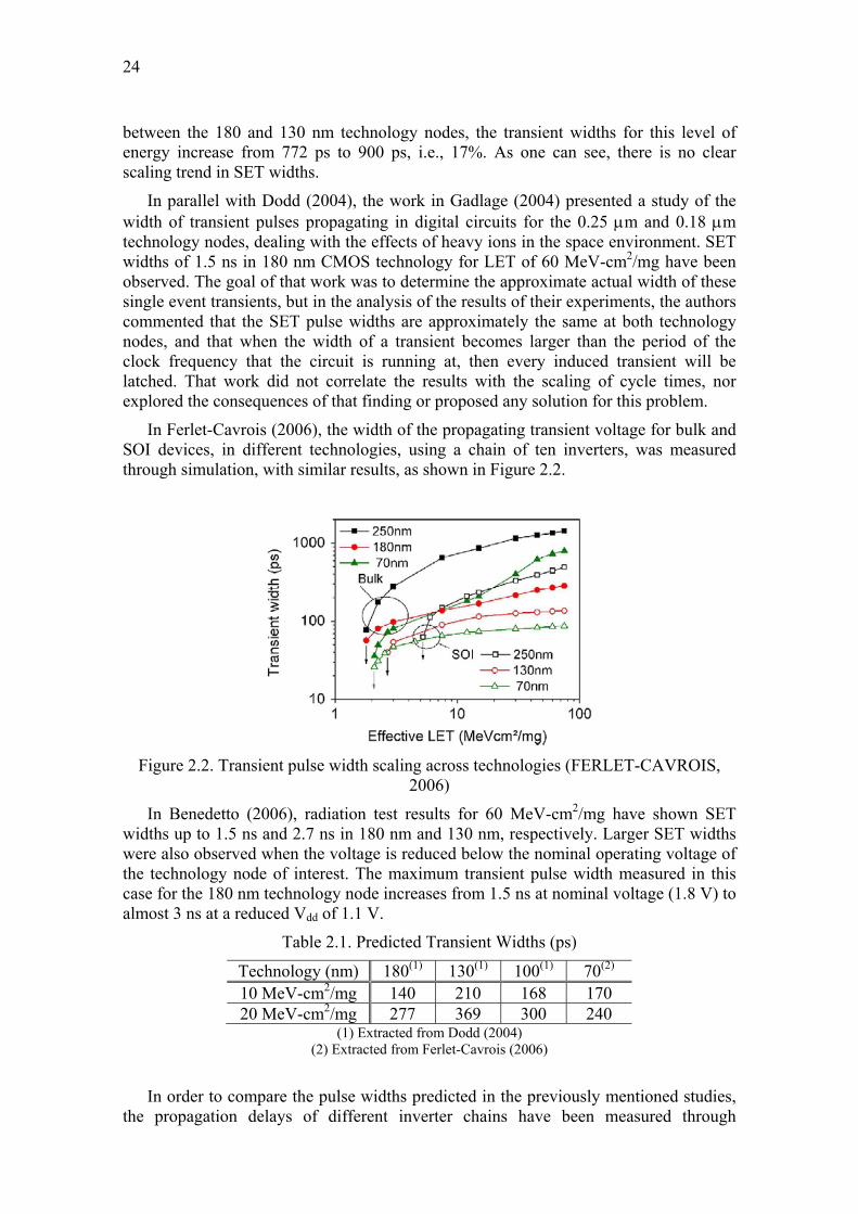
In Ferlet-Cavrois (2006), the width of the propagating transient voltage for bulk and SOI devices, in different technologies, using a chain of ten inverters, was measured through simulation, with similar results, as shown in Figure 2.2.
Figure 2.2. Transient pulse width scaling across technologies (FERLET-CAVROIS,
2006)
In Benedetto (2006), radiation test results for 60 MeV-cm2/mg have shown SET widths up to 1.5 ns and 2.7 ns in 180 nm and 130 nm, respectively. Larger SET widths were also observed when the voltage is reduced below the nominal operating voltage of the technology node of interest. The maximum transient pulse width measured in this case for the 180 nm technology node increases from 1.5 ns at nominal voltage (1.8 V) to almost 3 ns at a reduced Vdd of 1.1 V.
(1) Extracted from Dodd (2004) (2) Extracted from Ferlet-Cavrois (2006)
In order to compare the pulse widths predicted in the previously mentioned studies, the propagation delays of different inverter chains have been measured through
25
simulation, using the HSPICE tool and parameters from the Predictive Technology Model Web site (ARIZONA STATE UNIVERSITY, 2007) with default temperature of 25 degrees Celsius, and are shown in Table 2.2.
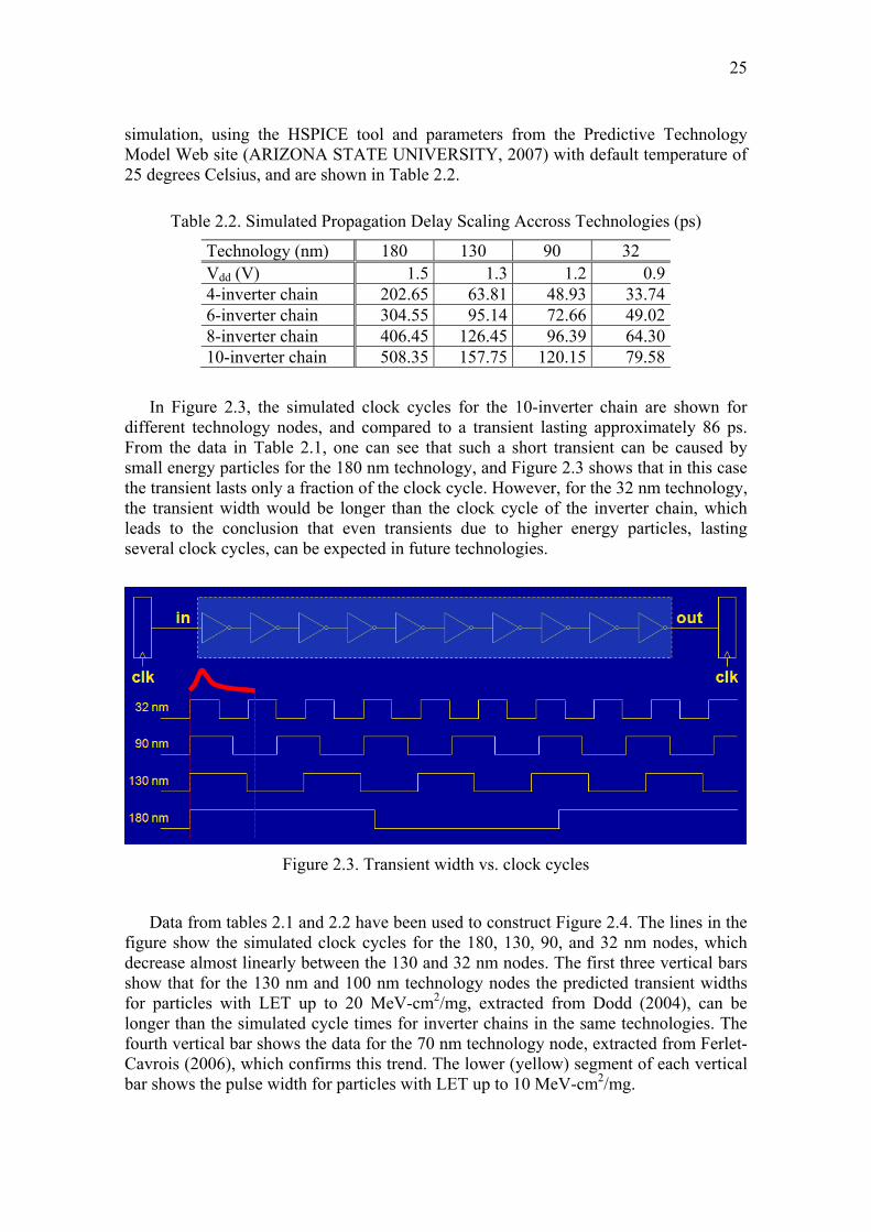
In Figure 2.3, the simulated clock cycles for the 10-inverter chain are shown for different technology nodes, and compared to a transient lasting approximately 86 ps. From the data in Table 2.1, one can see that such a short transient can be caused by small energy particles for the 180 nm technology, and Figure 2.3 shows that in this case the transient lasts only a fraction of the clock cycle. However, for the 32 nm technology, the transient width would be longer than the clock cycle of the inverter chain, which leads to the conclusion that even transients due to higher energy particles, lasting several clock cycles, can be expected in future technologies.
Figure 2.3. Transient width vs. clock cycles
Data from tables 2.1 and 2.2 have been used to construct Figure 2.4. The lines in the figure show the simulated clock cycles for the 180, 130, 90, and 32 nm nodes, which decrease almost linearly between the 130 and 32 nm nodes. The first three vertical bars show that for the 130 nm and 100 nm technology nodes the predicted transient widths for particles with LET up to 20 MeV-cm2/mg, extracted from Dodd (2004), can be longer than the simulated cycle times for inverter chains in the same technologies. The fourth vertical bar shows the data for the 70 nm technology node, extracted from Ferlet-Cavrois (2006), which confirms this trend. The lower (yellow) segment of each vertical bar shows the pulse width for particles with LET up to 10 MeV-cm2/mg.
26
Cycle time and transient width scaling across technologies
Figure 2.4. SET pulse width vs. cycle time scaling
By observing Figure 2.4, it is therefore straightforward to predict that in future
technologies the transient pulses may last longer than the clock cycles of these circuits. If no significant improvements are developed in the CMOS technology to reduce the collected charge, for very high speed circuits operating at 2 GHz and beyond (clock periods ≤ 500 ps), SETs may even last for several clock cycles.
As will be shown in Section 2.2, existing mitigation techniques are either unable to deal with this new scenario, or too expensive in terms of area, performance, and/or power overheads. Therefore, the use of low cost algorithm or system level techniques seems to be the most suitable approach to cope with LDTs, as will be further detailed in Chapters 3 through 6.
2.2 CURRENT MITIGATION TECHNIQUES VS. LDTS Many different error detection techniques aiming at the mitigation of soft errors in
software based systems have been proposed so far. They can be organized in three broad categories:
• software implemented techniques;
• hardware implemented techniques;
- time redundancy,
- space redundancy,
- checkers or I-IPs,
• hybrid techniques.
Software implemented techniques exploit detection mechanisms developed purely in software, with only extra memory as the allowed overhead. On the other side, hardware based techniques exploit the introduction of hardware modifications or extra hardware
27
addition. Finally, hybrid techniques combine both software and hardware error detection mechanisms.
Some of those techniques focus on checking the consistency between the expected and the executed program flow, recurring to the insertion of additional code lines or by storing flow information in suitable hardware structures, respectively. These are the control flow checking techniques. Another group of techniques checks the data that is read and written by the software, in order to detect SEUs affecting the stored data, and therefore are called data verification techniques. Selected proposed techniques belonging to those two groups are discussed in the following subsections.
Most of the proposed techniques rely on fault models that do not include neither the occurrence of multiple simultaneous transient faults or the possibility of transient pulses during longer than the clock cycle of circuits, and therefore a careful review of such techniques should be made in the near future, in order to ensure their compliance with this new scenario.
In the following subsections, the main techniques in each category are commented and their strengths and weaknesses concerning this scenario are briefly discussed.
2.2.1 Software Based Techniques SIHFT (Software Implemented Hardware Fault Tolerance) techniques exploit the
concepts of information, operation, and time redundancy to detect the occurrence of errors during program execution. In the past years some techniques have been developed that can be automatically applied to the source code of a program, thus simplifying the task for software developers: the software is indeed hardened by construction, and the development costs can be reduced significantly. Moreover, the most recently proposed techniques are general, and thus they can be applied to a wide range of applications. Unfortunately, most SIHFT techniques assume an unbounded memory, something that is not practical for low power or area constrained applications, since memories are responsible for most of the power dissipation and the area within a chip.
Techniques aiming at detecting the effects of faults that modify the expected program’s execution flow are known as control flow checking techniques. These techniques are based on partitioning the program’s code into basic blocks (sequences of consecutive instructions in which, in the absence of faults, the control flow always enters at the beginning and leaves at the end).
Among the most important solutions based on the notion of basic blocks proposed in the literature, there are the techniques called Enhanced Control Flow Checking using Assertions (ECCA) (ALKHALIFA, 1999) and Control Flow Checking by Software Signatures (CFCSS) (OH, 2002b).
ECCA is able to detect all the single inter-block control flow errors, but it is neither able to detect intra-block control flow errors, nor faults that cause an incorrect decision on a conditional branch. CFCSS cannot cover control flow errors if multiple nodes share multiple nodes as their destination nodes.
In Vemu (2007) a software based technique for detection and correction of control flow errors named ACCE (Automatic Correction of Control Flow Errors) is proposed. ACCE is an extension of a previous technique (VEMU, 2006) able to detect inter-node control flow errors. In ACCE the identification of the node from which the control flow error occurred is implemented, thereby allowing the correction of the error. Despite
28
being unable to mitigate all control flow errors, it provides correct results in 90% of the test cases using a set of benchmark applications. ACCE imposes very low latency for error correction, with a performance overhead of about 20%. This technique has brought several significant contributions, being considered by the authors as the first technique able to correct control flow errors at software level. One important feature of ACCE is the fact that it does not require any changes in the application code, since it is implemented through modifications introduced inside the compiler, with an extra pass in which the instructions required to implement ACCE are inserted at the beginning and at the end of each node of the control flow graph of the program. Since ACCE only deals with inter-node control flow errors, its error coverage can be increased by splitting nodes into subnodes, with increased performance and memory overheads.
In order to achieve system level hardening against transient errors, the authors propose the use of ACCE combined with some algorithmic fault tolerance mechanisms able to cope with errors affecting data. Experiments in which ACCE has been combined with ABFT have shown a marginal increase in the correctablity, from 89.5% to 91.6%, while increasing the detectability from 92% to 97%. Finally, an enhanced version of the technique, named ACCED, which combines ACCE with the Selective Procedure Call Duplication (SPCD) has been implemented and the experiments have shown that the combination of both techniques increase both the correctablity and detectability of ACCE.
As far as faults affecting program data are considered, several techniques have been proposed that exploit information and operation redundancies (CHEYNET, 2000), (OH, 2002a). Such approaches modify the source code of the application to be hardened against faults by introducing information redundancy and instruction duplication. Moreover, consistency checks are added to the modified code to perform error detection. The approach proposed in Cheynet (2000) exploits several code transformation rules that mandate for duplicating each variable and each operation among variables. Furthermore, each time a variable is read, a consistency check between the variable and its replica should be performed.
Conversely, the approach proposed in Oh (2002a), named Error Detection by Data Diversity and Duplicated Instructions (ED4I), consists in developing a modified version of the program, which is executed along with the unmodified program. After executing both the original and the modified versions, their results are compared: an error is detected if any mismatch is found. Both approaches introduce overheads in memory and execution time.
By introducing consistency checks that are performed each time a variable is read, the approach proposed in Cheynet (2000) minimizes the latency of faults; however, it is suitable for detecting transient faults only, since the same operation is repeated twice. Conversely, the approach proposed in Oh (2002a) exploits diverse data and duplicated instructions, and thus it is suitable for both transient and permanent faults. As a drawback, its fault latency is generally greater than in Cheynet (2000). The ED4I technique requires a careful analysis of the size of used variables, in order to avoid overflow situations.
SIHFT techniques are appealing, since they do not require modification of the hardware running the hardened application, and thus in some cases they can be implemented with low costs. However, although very effective in detecting faults affecting both program execution flow and program data, the software implemented approaches may introduce significant time overheads that limit their adoption only to
29
those applications where performance is not a critical issue. Also, in some cases they imply a non-negligible increase in the amount of memory needed for storing the duplicated information and the additional instructions. Finally, these approaches can be exploited only when the source code of the application is available, precluding its application when commercial off-the-shelf software components are used.
In this thesis work, the focus has been on techniques for detection and correction of transient errors affecting the data used by the system, and not on control flow errors. Considering that no system can be completely hardened without control flow errors mitigation, this will be an important field for future research, as discussed in Chapter 7.
2.2.2 Hardware Based Techniques Hardware based techniques must be implemented during the design phase of the
system to be hardened. Therefore, they are not suited for the protection of commercial off-the-shelf (COTS) processors targeted at the general purpose market, and their implementation is restritcted to application specific integrated circuits (ASICs) or FPGA based designs. Those techniques can be classified as redundancy based ones, which can rely on time or space redundancy, and those using watchdogs, checkers or IPs to monitor the main processor operations watching for errors.
2.2.2.1 Time Redundancy
Hardware based techniques using time redundancy rely in the verification of the outputs generated by the circuit by comparing their values at two different moments in time, separated by a fixed delay. Those techniques rely on the single fault model and also in the concept that the duration of the transient pulse is short, and for this reason the introduction of the delay does not impact performance very much. Examples of such techniques are shown in Anghel (2000a; 2000b), and Mitra (2005). Also, in Austin (2004), the same concept is used to check the outputs of a circuit and tune the soft error rate by dynamically adjusting the voltage, aiming to reduce the power consumption.
In Figure 2.5, extracted from Anghel (2000), one can see an example of temporal redundancy based technique, in which the outputs of the circuit to be protected are sampled twice, at different moments in time separated by a fixed delay δ, and the obtained values are compared. When they are different, an error is flagged. Schematics (a) and (b) show different alternatives for the implementation of the delayed sampling of outputs, and drawing (c) shows how the double sampling allows the detection of the transient induced fault.
Considering the durations of the transient pulse (Dtr,) and of the delay between outputs sampling (δ), shown in Fig. 2.5(c), the following situations may occur:
• The transient hits the circuit and is completely dissipated either before O1 is sampled or after O2 is sampled. In this case, no matter the duration of the transient, the two sampled outputs will be equal and correct, and the transient will not affect the results generated by the circuit.
• The transient hits the circuit before O1 is sampled and is completely dissipated before O2 is sampled, or hits the circuit after O1 is sampled and vanishes after O2 is sampled. In this case, no matter the duration of the transient, the two sampled outputs will be different, and an error will be properly flagged by the technique.
• The transient hits the circuit after O1 is sampled and is completely dissipated before O2 is sampled. In this case, the two sampled outputs will also be equal and correct, and no harm to the generated output will happen. However, to ensure that this situation leads to correct operation of the technique, the duration of the transient, Dtr, must clearly be shorter than δ. In case longer duration transients (larger Dtr values) are expected, the duration of δ must be increased accordingly, to ensure correct operation.
• Finally, if δ is not long enough, there will be situations in which the transient hits the circuit before O1 is sampled and is completely dissipated only after O2 is sampled, i.e., the duration of the transient, Dtr, is longer than δ. In this case, the two outputs will be equal, however, their value will be incorrect and this will not be properly detected by the technique. This situation is depicted in Figure 2.6, adapted from Anghel (2000).
In order to avoid the possibility of failure of the technique in the third and fourth situations described above, the only remedy is to increase the duration of δ.
Figure 2.6. Long duration transient effect – adapted from Anghel (2000)
Therefore, in order to keep the correctness of temporal redundancy based techniques in future technologies, when the duration of the transient pulses is expected to be much larger than the average circuit cycles, it will be necessary to increase the duration of the delay δ used to separate the output values to be compared. And this is a penalty imposed at every operation cycle, which will imply unbearable performance overheads.
As a consequence, the application of such techniques will be negatively impacted by the occurrence of long duration transient pulses in the near future.
2.2.2.2 Space Redundancy
The group of space redundancy based techniques is more likely to provide protection even in the presence of long duration transient pulses, because, under the
31
single fault model, which is still the dominant one (ROSSI, 2005), only one of the copies of the circuit would be affected by the long duration transient, and the other(s) would provide correct results.
The technique called duplication with comparison (WAKERLY, 1978) would allow only the detection of errors caused by long duration transients, while in the case of triple modular redundancy the circuit would be able to detect the error and also choose the correct result, discarding the wrong one caused by the long duration transient.
Another approach in this group is proposed in Nieuwland (2006), where the critical path of combinational circuits is hardened through the duplication of gates and transient errors are mitigated (actually, masked) thanks to the extra capacitance available in the node. This technique also relies on the single fault model.
However, the area and mainly power penalties imposed by solutions using space redundancy are a big concern, mainly for embedded systems. For this reason, the development of innovative techniques in this group providing lower costs has also been included as one of the goals this research work, leading to the technique described in Chapter 6.
2.2.2.3 Mitigation Techniques Based on Watchdogs, Checkers and IPs
The third group of hardware based techniques relies in the use of special purpose hardware modules, called watchdog processors (MAHMOOD, 1988), checkers (AUSTIN, 1999), or infrastructure IPs (LISBOA, JETTA 2007), to monitor the control flow of programs, as well as memory accesses. The behavior of the main processor running the application code is monitored using three types of operations.
Memory access checks consist in monitoring for unexpected memory accesses executed by the main processor, such as in the approach proposed in Namjoo (1982), where the watchdog processor knows at each time during program execution which portion of the program’s data and code can be accessed, and activates an error signal whenever the main processor executes an unexpected access.
Consistency checks of variables contents consists in controlling if the value a variable holds is plausible. By exploiting the knowledge about the task performed by the hardened program, watchdog processors can validate each value the main processor writes or reads through range checks, or by exploiting known relationships among variables (MAHMOOD, 1983).
Control flow checks consist in controlling whether all the taken branches are consistent with the program graph of the software running on the main processor (NAMJOO, 1983), (OHLSSON, 1995), (SCHUETTE, 1987), and (WILKEN, 1990). As far as the control flow check is considered, two types of watchdog processors may be envisioned.
An active watchdog processor executes a program concurrently with the main processor. The program graph of the watchdog’s program is homomorphic to the main processor’s one. During program execution, the watchdog continuously checks whether its program evolves as that executed by the main processor or not (NAMJOO, 1983). This solution introduces minimal overhead in the program executed by the main processor; however, the area overhead needed for implementing the watchdog processor can be non-negligible.
32
A passive watchdog processor does not execute any program; conversely, it computes a signature by observing the bus of the main processor. Moreover, it performs consistency checks each time the main program enters/leaves a basic block within the program graph. A cost-effective implementation is described in Wilken (1990), where a watchdog processor observes the instructions the main processor executes, and computes a runtime signature. Moreover, the code running on the main processor is modified in such a way that, when entering a basic block, an instruction is issued to the watchdog processor with a pre-calculated signature, while the main processor executes a NOP instruction. The watchdog processor compares the received pre-computed signature with that computed at runtime, and it issues an error signal in case of mismatch. An alternative approach is proposed in Ohlsson (1995), where the watchdog processor computes a runtime signature on the basis of the addresses of the instructions the main processor fetches. Passive watchdog processors are potentially simpler than active ones, since they do not need to embed the program graph and they perform simpler operations: signature computation can be demanded to LFSRs, and consistency checks to comparators. However, an overhead is introduced in the monitored program: instructions are indeed needed for communicating with the watchdog.
Dynamic verification, another hardware-based technique, is detailed in Austin (2000) for a pipelined core processor. It uses a functional checker to verify the correctness of all computation executed by the core processor. The checker only permits correct results to be passed to the commit stage of the processor pipeline. The so-called DIVA architecture relies on a functional checker that is simpler than the core processor, because it receives the instruction to be executed together with the values of the input operands and of the result produced by the core processor. This information is passed to the checker through the re-order buffer (ROB) of the processor’s pipeline, once the execution of an instruction by the core processor is completed. Therefore, the checker does not have to care about address calculations, jump predictions and other complexities that are routinely handled by the core processor.
Once the result of the operation is obtained by the checker, it is compared with the result produced by the core processor. If they are equal, the result is forwarded to the commit stage of the processor’s pipeline, to be written to the architected storage. When they differ, the result calculated by the checker is forwarded, assuming that the checker never fails (which is a risky assumption). If a new instruction is not released for the checker after a given time-out period, the core processor’s pipeline is flushed, and the processor is restarted using its own speculation recovery mechanism, executing again the instruction. Originally conceived as an alternative to make a core processor fault tolerant, this work evolved later to use a similar checker to build self tuning SoCs (WILKEN, 1990).
While being a well balanced solution, in terms of area and performance impacts, the DIVA approach has two main drawbacks. First, since the checker is implemented inside the processor’s pipeline, it cannot be implemented in SoCs based on COTS processors or FPGAs that have an embedded hardwired off-the-shelf processor, such as an ARM or Power PC core. Second, the fundamental assumption behind the proposed solution is that the checker never fails, due to the use of oversized transistors in its construction and also to extensive verification in the design phase. In case this is not feasible, the authors suggest the use of conventional alternatives, such as TMR and concurrent execution with comparison, which have been already studied in several other works.
33
The approaches discussed in this subsection usually imply in a high performance overhead, since the results must be computed twice, and also in an area overhead, due to the addition of the watchdog, checker or I-IP. Even in solutions where part of the verification is executed in parallel with the main one, such as Rhod (JETTA 2008), the performance overhead is still significant.
2.2.3 Hybrid Techniques Hybrid techniques combine SIFHT and hardware based techniques. One such
technique is described in Bernardi (2006), and it combines the adoption of some SIHFT techniques in a minimal version (thus reducing their implementation cost) with the introduction of an I-IP into the SoC. The software running on the processor core is modified so that it implements instruction duplication and information redundancy; moreover, instructions are added to communicate to the I-IP the information about basic block execution. The I-IP works concurrently with the main processor, it implements consistency checks among duplicated instructions, and it verifies whether the correct program’s execution flow is executed by monitoring the basic block execution.
Hybrid techniques are effective, since they provide a high level of dependability while minimizing the introduced overhead, both in terms of memory occupation and performance degradation. However, in order to be adopted they mandate the availability of the source code of the application the processor core should run, and this requirement cannot be always fulfilled.
The idea of introducing an I-IP between the processor and the instructions memory, and of charging the I-IP of substituting on-the-fly the fetched code with hardened one, was preliminarily introduced in Schillaci (2006). However, the I-IP proposed in Schillaci (2006) is very simple (it does not include either an ALU or a control unit), and is not supported by a suitable design flow environment. Moreover, the performance overhead of the method in Schillaci (2006) is significant, and the method cannot cover permanent faults.
In Rhod (JETTA 2008), an approach aiming to minimize the overhead needed to harden a processor core has been proposed. The method is based on introducing in the SoC a further module (I-IP), whose architecture is general, that needs to be customized to the adopted processor core. The I-IP monitors the processor buses and performs two main functions: when the processor fetches a data processing instruction belonging to a design time selected set, it acts on the bus and lets the processor fetch a sequence of instructions generated on-the-fly, instead of the original one. This sequence of instructions allows the I-IP to get the operands of the original data processing instructions, which is then executed both by the processor and by the I-IP; the results obtained by the processor and the I-IP are then compared for correctness. Each time the processor fetches a new instruction, the I-IP also checks the correctness of the address used by the processor, by comparing it to the expected one, and an error is notified if a mismatch is found, thus allowing also the detection of control flow errors.
The method is inspired in SIHFT and hybrid techniques, but it does not introduce any memory overhead in the hardened system (code redundancy is introduced on-the-fly). Moreover, no change is required on the application code, whose source version is not required to be available. Finally, the method allows designers to trade-off costs and reliability, mainly by suitable selecting the subset of data-manipulation instructions to be hardened. Fault injection experiments using the proposed technique implemented in a MIPS processor have shown that most of the non detected errors are due to SEUs
34
affecting the register file of the processor before the operands are read and their values forwarded to the I-IP. In order to avoid these errors, the register file should be protected using EDAC techniques, what would imply in changes in the internal architecture of the processor.
Another hybrid technique to mitigate SETs in combinational logic based on duplication and time redundancy, and code word state preserving (CWSP), is shown in Nicolaidis (1999). The CWSP stage replaces the last gates of the circuit by a particular gate topology that is able to pass the correct value in the combinational logic in the presence of a SET. In the case of duplication, when the two copies of the inputs are identical (code word), the next state is equal to the corresponding output of the function, but if the two copies of the inputs are not identical (non-code word), the next state remains equal to the present state. Using time redundancy, one of the inputs of the CWSP element is coming directly from the combinational circuit output, while the other input comes from the same output signal, but is delayed. The use of this method requires the modification of the CMOS logic in the next stages by the insertion of extra transistors and the necessity of using duplicated logic or logic to implement a delay. Furthermore, being also a time redundancy based technique, it will suffer from the same drawbacks already discussed in subsection 2.2.2.1, since it will not withstand LDTs.
2.3 PROPOSED APPROACH TO DEAL WITH LDTS As shown in the previous section, most of currently known soft errors mitigation
techniques will not be useful in the future scenario, where radiation induced transients will last longer than the cycle time of circuits and the probability of multiple simultaneous upsets will become higher due to the small distances between the devices. Time redundancy based techniques will become too expensive, in terms of performance overhead, due to the need for an increased delay between two or three inputs sampling, which must be longer than the expected transient width. Space redundancy based ones, in turn, will still impose too heavy penalties in terms of area and power overheads, making them useless for applications fields in which those are scarce resources, such as the embedded systems arena. Finally, software based techniques will continue to suffer from the need to modify existing software or impose high area and/or performance overheads.
Given this scenario, this work proposes the development of a set of innovative low cost techniques, each one working at a different abstraction level in a complementary fashion, in order to face the challenges imposed to designers by future technologies. While the development of a complete set of such solutions, able to harden a whole system against soft errors, is out of the scope of this thesis text, this is the ultimate goal of our research project.
Very recently, in Albrecht (2009), a generic approach to deal with the drawbacks imposed by future technologies in the design of systems-on-chip has been proposed. The authors propose to divide the SoC into several architectural layers, each one tailored to the specific SoC fault-tolerance needs, aiming to cope with the decreasing device reliability due to parameters variations, temperature impact, and radiation effects. While the ideas behind this proposal have some common points with the ones proposed in Lisboa (ETS 2007), in Albrecht (2009) the authors suggest that the detection of errors should be implemented at lower levels, while the error correction should be performed at system level. In order to achieve this goal, mechanisms for fault detection and communication with upper levels should be implemented at the lower
35
levels, while the upper levels would implement the error correction mechanisms and also the ability to switch on and off the error detection mechanisms in lower levels, according to the specific fault tolerance requirements of the application. So, that proposal aims to define a configurable reliable design, able to deal not only with runtime, but also with design and production errors. However, no new error detection or correction technique is proposed in that work, and the authors simply make a review of existing alternatives, without any comments about their suitability to cope with the new scenario. Furthermore, the authors state that the overall system reliability is becoming more important than the mips-per-watt measure, thereby suggesting that performance and power overheads are not as important as the reliability features in a SoC.
In our work, in turn, the development of new low cost techniques to deal with the new challenges at different abstraction levels is proposed, but with reduced overheads In terms of area, power, and performance, as the first goal. While most of the solutions proposed in this thesis aim to detect errors, some of them also include error correction capabilities. As a general rule, our proposal is to correct errors through recomputation, which sometimes may seem to be a very expensive solution. However, it must be highlighted that when one deals with radiation induced errors, given the very low frequency of SETs in comparison with the operating frequencies of the circuits, the recomputation cost becomes almost negligible. Nevertheless, the reduction of the recomputation cost itself has also been a concern in our work, as is detailed in the description of the technique presented in Chapter 3.
For the purpose of this work, we have considered the following abstraction levels in a system:
• technology level
• component level
• circuit level
• architecture level
• algorithm or software level
• system level
At the technology level, the use of built-in current sensors, proposed in Neto (2006), is a possible approach to detect soft errors, as shown in Lisboa (ITC 2007) and Albrecht (2009), but the error correction capability must then be implemented at higher abstraction levels.
At the component level, given the possibility of transients lasting even longer than the propagation times of circuits, the use of space redundancy, under the single fault assumption, is the most suitable alternative. However, the area and power overheads imposed by space redundancy preclude the use of this option when designing portable or embedded systems. Another approach is to oversize the most sensitive transistors used in the construction of the component, but then again the area overhead becomes too high. Due to those considerations, in our work there are no studies for error detection or correction at the component level.
When working at circuit level, many alternative techniques have already been proposed. As previously mentioned, those based on time redundancy will be useless in the presence of LDTs. Space redundancy techniques, such as DWC, TMR, and the use of IPs or checkers operating in parallel with the circuit to be protected, can indeed cope
36
with LDTs, but usually impose heavy penalties in terms of area and power. With this in mind, one of the new low overhead solutions proposed in this thesis is the use of Hamming codes to protect combinational logic, as described in Chapter 6.
Considering the use of commercial off-the-shelf processors in the implementation of the system to be hardened, the mitigation of soft errors at the architecture level is usually restricted to space redundancy techniques such as TMR. However, the growing availability of multi-processor FPGAs, which allow the addition of custom logic around the COTS processors, opens new paths to be explored in the search for soft error mitigation alternatives. As an example of this approach, the use of the lockstep technique, combined with checkpoint and rollback, already proposed in the past but precluded due to the need to the high costs involved in the design and manufacturing of ASICS, is now becoming again a feasible option. Due to this fact, in this thesis this technique has been studied and an improvement at the architecture level that reduces the time required to perform checkpoints has been proposed, as described in Chapter 5.
Despite the studies aiming to deal with the problem at lower abstraction levels, as proposed in Lisboa (ETS 2007) our preferred alternative to deal with the effects of LDTs is to work at algorithm level or system level. And with this in mind, our efforts have been concentrated in the search for low cost alternatives to accomplish our goal. Starting with the matrix multiplication algorithm, for which a verification technique with single element recomputation at extreme low cost has been devised, the work has continued with the use of software invariants in the runtime detection of soft errors. In both cases, the low cost goal has been achieved, and the proposed solutions seem good candidates to be included together with future ones in the hardening of complete systems against radiation induced long duration transient faults.
In the following chapters, the main results of our research work during the thesis development are presented and discussed.
37
3 MATRIX MULTIPLICATION HARDENING
This part of the thesis describes a technique able to detect and correct errors affecting a single element of the product in matrix multiplication operations which provides a significant cost reduction when compared with classic solutions such as duplication with comparison (error detection only) and triple modular redundancy (error detection and correction).
Once the conclusion that mitigation techniques working at low level would not be suitable to deal with long duration transients and multiple simultaneous faults has been reached, our research work has been directed to the search of low cost algorithm level solutions. At this level, the first task has been to harden the matrix multiplication algorithm, a widely used one that has applications in several fields. After studying some of the formerly proposed solutions to the problem, our focus has been concentrated in the study of a probabilistic solution proposed in Freivalds (1979). The analysis of that technique, which is able to detect errors affecting a single element of the product matrix with a probability higher than ½, has led the author to the conclusion that it could be improved in order to provide deterministic error detection, i.e., to detect the same type of errors with a probability equal to one.
The first experimental results showing the proposed technique have been presented in Lisboa (LATW 2007) and Lisboa (ETS 2007), when the author received the suggestion to compare his proposal with the well known technique named algorithm based fault tolerance – ABFT (HUANG, 1984), which has been proposed for the hardening of large matrices multiplication performed by a network of processors. Along the research, the work by Prata (1999), comparing Freivalds’ technique (named there as result checking), the starting point of our work, to ABFT has also been used as a reference and is commented in Section 3.2.
Initially targeting only the detection of the error, with recomputation of the whole product matrix when an error was detected, as described in section 3.3.1, along the research the proposed technique evolved to several alternative solutions providing different computational costs and correction latency features. The exploration of the possible alternatives has been conducted in cooperation with Costas Argyrides, a PhD student at University of Bristol, UK (section 3.3.2), and with Fernanda Lima Kastensmidt and Gilson Wirth, co-workers at the Computer Science (PPGC) PhD program in Instituto de Informática (UFRGS, Brazil), as described in section 3.3.3. The development of the technique and its improvements led to the publication of several papers, such as (LISBOA, ITC 2007), (LISBOA, VTS 2008), (LISBOA, WREFT 2008), (LISBOA, DFR 2008), and (Argyrides, IOLTS 2009).
38
In addition to the development of the technique itself, radiation injection experiments and measurements have been conducted in cooperation with Eduardo Rhod, a Microelectronics (PGMicro) PhD student at Instituto de Informática (UFRGS, Brazil), and Paul Perronard and Raoul Velazco, working at the TIMA Laboratoire, at the Institut National Polytechnique, in Grenoble, France. The results obtained in those experiments have been presented in Lisboa (RADECS 2008) and are described in Section 3.3.4.
The extension of the technique for use with non-square matrices and vectors has also been the subject of analysis, but not yet published. The conclusions of those studies are described in Section 3.3.5.
3.1 PROBLEM DEFINITION For this step of the research, the matrix multiplication algorithm has been selected as
the case study, since matrix operations are an important tool for several applications, such as signal and image processing, weather prediction and finite element analysis, and often the performance of those systems depends on the speed of these operations (HUANG, 1984).
Considering that applications such as audio, video, graphics, and visualization processing, share the ability to tolerate certain types of errors at the system outputs, once those errors are within acceptable boundaries, a new application oriented paradigm to deal with process variations, defects, and noise, named error tolerance (ET), is proposed in Breuer (2004). However, even error tolerant applications have maximum acceptable error limits, and therefore the search for techniques that can mitigate radiation induced errors is an important contribution to keep the overall error rate below those limits.
Aiming to provide higher overall yield rates, by enabling the use of systems that otherwise would be discarded, the application of system-level error tolerance techniques to multimedia compression algorithms has been proposed in Chong (2005), Chung (2005). In Chong (2005), the application of ET for a JPEG encoder has shown that more than 50% of single stuck-at interconnection faults in one of its 1D DCT modules resulted in imperceptible quality degradation in the decoded images. In Chung (2005), an ET based application oriented design and test scheme was applied to three different possible architectures of a motion estimation system, and proven to increase the yield rate.
Due to those considerations, the matrix multiplication algorithm was selected with the initial purpose of developing an error tolerant technique for matrix multiplication, which further led to the deterministic solution described in Section 3.3.1.2. In order to further exercise the application of the proposed approach, this case study has also been applied at different levels of granularity, and the computational cost of the alternatives have been compared, as described in Section 3.3.3.
Given two n×n matrices, the number of required arithmetic operations for matrix multiplication is O(n3). However, since additions and multiplications are used in the matrix multiplication algorithm, throughout this work we consider the cost of each type of operation separately, with the cost of multiplications being estimated as 4 times the cost of additions, as shown in Table 3.1. As to the comparison operations required for error detection, which are considered in the computational cost analysis and comparison, their cost is assumed to be equal to that of additions.
39
As one can see in Table 3.1, the computational cost of matrix multiplication grows very fast with the number of lines and columns, which makes the recomputation of the whole product matrix, when an error is detected, a very expensive solution. Alternative solutions, aiming to minimize the recomputation cost, and also the trade-offs between recomputation cost and error verification frequency have also been considered along the research and are discussed in Sections 3.3.2 and 3.3.3.
Table 3.1 – Matrix multiplication computational cost scaling with n
Another important issue is the maximum time that a given system may run after the occurrence of an error, before this error leads to unrecoverable damages. Therefore, the error detection latency has also been a matter of study and is discussed in Section 3.3.3.
3.2 RELATED AND PREVIOUS WORK One classic technique used to detect errors in the execution of an algorithm, named
duplication with comparison (DWC), is to execute it twice and compare the results (WAKERLY, 1978). This allows the detection of errors, but not the identification of the correct result. Therefore, in order to recover from an error, the duplicated operation must be repeated and checked again, with a total computational cost equal to four times the cost of a single operation plus the cost of comparisons.
Triple modular redundancy (TMR), which executes three times the operation and then votes for the correct result using majority, is another alternative (JOHNSON, 1994). For the single error hypothesis, and assuming the voter does not fail, it allows detecting errors and choosing the correct result without recomputation. However, its cost is still higher than three times the cost of a single operation, due to the additional cost of voting.
The use of checksums for detection and correction of errors in matrix multiplication is a classic technique proposed in Huang (1984) and named algorithm based fault tolerance (ABFT). Proposed for use in the manipulation of large matrices, handled in parallel by multiple processors, this technique can also be used to multiply smaller matrices, using a single processor, providing reduced cost error detection and correction. As proposed by Huang, “ABFT is based on the encoding of the data used by the algorithm, the redesign of the algorithm to operate on the encoded data, and the distribution of the computation steps in the algorithm among computation units” (HUANG, 1984). This approach provided low cost fault tolerance, however it is applied by tailoring the fault tolerance scheme to the algorithm to be performed, which implies in high algorithm adaptation costs.
Another approach, named result checking, was proposed in Rubinfeld (1990), where several mathematical computations, including matrix multiplication, are analyzed
40
aiming the definition of programs to check the result of the computation in a time that is less than that required to recompute the whole function.
More recently, in Prata (1999), the application of ABFT and result checking specifically to matrix multiplication algorithms has been evaluated. In Prata (1999) the authors used the Freivalds’ technique, proposed in Freivalds (1979), for matrix multiplication result checking, which detects errors with a given probability. They executed twice the technique in order to obtain a higher probability of error detection (only 2.7% of undetected errors). Nevertheless, the error detection in their experiments was still probabilistic.
According to Prata (1999), both ABFT and result checking provide a good fault coverage, and equivalent execution time, since they provide checkers that can be executed with O(n2) operations for an algorithm that requires O(n3) operations.
However, Prata (1999) also states that ABFT is superior to result checking because it is able not only to detect, but also to localize and correct errors. Despite that, they claim that result checking has a lower calculation time overhead for equivalent fault coverage levels, and that it is easier to implement than ABFT, requiring less additional code in order to harden the algorithm. Finally, they state that result checking can be applied to any matrix multiplication algorithm, while ABFT depends on the particular algorithm that is used.
Also starting from the Freivalds’ result checking technique (FREIVALDS, 1979), the author developed a new approach for algorithm level error detection in matrix multiplication that led to a deterministic technique, i.e., able to detect errors with probability equal to 1. The proposed technique has been first presented in Lisboa (ETS 2007) and has a computational cost comparable to that of checksums used in ABFT.
3.3 PROPOSED TECHNIQUE In this section, we describe the proposed technique, as presented in Lisboa (ETS
2007), and its extension in cooperation with other research groups to include the localization and correction of the error, thereby overcoming the main drawback of the result checking approach highlighted in Prata (1999). Furthermore, the comparison of the computational cost of the proposed technique for different error verification granularities, as well as the error latency and cost vs. recomputation time tradeoffs are discussed here.
3.3.1 Background and Evolution of the Proposed Technique
3.3.1.1 The starting point: fingerprinting and Freivalds’ technique
The concept of processing and checking in parallel the outputs of a system for only a subset of its possible inputs, also called fingerprinting (MOTWANI, 1995), can be applied to the general case of a circuit that must be hardened against soft errors, thus providing tolerance against transient faults caused by pulses that affect parts of the circuit, even when the duration of the transient pulse is longer than the delay of several gates. Figure 3.1 illustrates this idea.
In contrast with other proposed solutions based on checker circuits, such as the one proposed by Austin (1999), when fingerprinting is applied the random checker does not provide full fault detection. It performs some of the functions of the main circuit only on a small set of possible inputs, being able to statistically detect errors at the output
41
with a given probability. The main goal of this approach is to provide an acceptable level of fault detection, according to the concepts of error tolerance, using a circuit that is significantly smaller than the main circuit under inspection, thereby providing low area overhead.
Figure 3.1. Fingerprinting - generic scheme
The underlying concept presented here is generic, and can be adopted for several
different applications or circuits, with the subset of inputs, the operations performed by the checker, the performance, area, and power overheads varying according to the application. In this work, it has been applied to harden a matrix multiplier circuit, as shown in the following paragraphs.
In 1977, Rúsiņš Freivalds (1977) proved that probabilistic machines are able to execute some specific computations faster than deterministic ones, and that they can compute approximations of a function in a fraction of the time required to compute the same function deterministically. Also credited to Freivalds, a technique for faster verification of the correctness of matrix multiplication algorithms has been shown in Motwani (1995).
In summary, Freivalds’ technique proposes the use of multiplication of matrices by vectors in order to reduce the computation time when verifying the results produced by a given matrix multiplication algorithm, as follows: given n×n matrices A and B, and the matrix C, the product of A and B which was computed using the algorithm under test, the following computations are performed:
1. Randomly create a vector r in which the values of the elements are only 0 or 1.
2. Calculate Cr = C × r
3. Calculate ABr = A × (B × r)
Freivalds has proven that, whenever A×B ≠ C, the probability of Cr being equal to ABr is ≤ ½. In other words, when A×B = C the probability of the product matrix being correct is higher than ½. The demonstration is shown in Motwani (1995).
Furthermore, if steps 1 to 3 above are performed k times independently (with different values of the vector r), the probability becomes ≤ ½k. Using this technique, the verification of the result can be done in less time than the original multiplication, since matrix multiplication requires O(n3) time to be performed, while multiplication of a matrix by a vector is performed in O(n2) time. However, since this is a statistical technique, there is no assurance that errors will always be detected.
3.3.1.2 Improving Freivalds’ technique
The analysis of the technique proposed by Freivalds shows that the probability of detecting one error in C is ≅ ½ because the randomly generated elements of the vector r have the same ½ probability of being 0 or 1. Assuming that the element of C which has
main circuit
random checker
inputs output
error
42
an erroneous value is Cij, in the calculation of Cr this element is multiplied by a single element rk of the vector, thereby being canceled during the generation of Cr (if rk is equal to 0) or not (when rk is equal to 1).
Given that the elements of the vector r can be randomly chosen, if we perform the computation with a second vector, rc, in which each element is the binary complement of the values in r, the elements of C that were cancelled in the first computation will not be canceled in the second one, and vice-versa. Therefore, if Cij has an erroneous value, we will either have A×(B×r) ≠ C×r or A×(B×rc) ≠ C×rc, and the probability of detecting an error in a single element of C will be equal to 1, i.e., if the erroneous value is masked in the calculation of ABr/Cr, it is not masked when ABrc/Crc are calculated, and vice versa.
This property allows the detection of every error in which a single element of C is faulty, with only two executions of the Freivalds technique, as demonstrated in the following box.
Theorem: The use of complementary r and rc vectors allows to detect all single faults with a double execution of Freivalds’ technique.
The computation of the products A×(B×r) and C×r in the Freivalds technique generates two vectors that must be compared. Assuming that matrices A and B have n×n elements, the r and rc vectors will have n elements each and the value of an element i of the above products is given by:
As demonstrated in Motwani (1995), when no error occurs in the calculation of C, we have ABr = Cr, and regardless of the values of ri the comparison for equality will hold true. However, when ABr ≠ Cr there is a probability ≤ ½ that the comparison will also hold true. That happens because the values of ri are selected randomly from {0, 1} and, therefore,
Pr[ri = 0] = Pr[ri = 1] = ½.
This way, there is a 50% chance that an erroneous value Cij will be masked during the calculation of Cr, and, in this case, ABr is erroneously considered to be equal to Cr.
When the ri values are generated randomly, and then the complement of their values are used to set the values of the corresponding elements in vector rc, we have:
Pr[ri=1 OR rci=1] = Pr[ri=1] ∪ Pr[ rci=1]
= Pr[ri=1] + Pr[ rci=1]
= ½ + ½ = 1
Further exploring the extension of Freivalds’ technique here proposed, it becomes clear that, since the technique is valid for any randomly selected r vector, it must also be valid for the specific vector r1 = {1, 1, ..., 1}. In this case, the complementary vector is r0 = {0, 0, ..., 0}, and we have:
C×r1 = {Σnj=1 C1j, ..., Σn
j=1 Cnj} (1)
43
A×(B×r1) = {Σnj=1 (Σn
k=1 A1k . Bkj), ... , Σnj=1 (Σn
k=1 Ank . Bkj)} (2)
and
C×r0 = 0 (3)
A×(B×r0) = 0 (4)
From expressions (3) and (4) above, one can see that the condition C×r0 ≠ A×(B×r0) will always be false, and therefore the test of the compound condition A×(B×r1) ≠ C×r1 or A×(B×r0) ≠ C×r0 can be simplified to A×(B×r1) ≠ C×r1, significantly reducing the cost of the verification process, because the computation of expressions (3) and (4) is no longer necessary. In addition, in the computation of the expressions (1) and (2) there is no longer need to multiply by the elements of r1, since they all are equal to one.
From (1) and (2), we can also conclude that, since in the multiplication process Cij = Σn
k=1 Aik . Bkj, if one of the Cij elements has an erroneous value, the condition A×(B×r1) ≠ C×r1 will be true, and the error will always be detected.
(Expression 5)
(Expression 6)
(Expression 7)
Figure 3.2: Operations used in the verification of the product
Therefore, the verification of the product matrix can be performed only by calculating the following:
• Vector Br, where Bri = Bi1 + Bi2 + ... + Bin (6)
• Vector ABr, where ABri = Σnk=1 Aik . Brk (7)
44
Then, vectors ABr and Cr must be compared; if they are different, there was an error in the multiplication, and the whole matrix multiplication algorithm must be repeated.
The above conclusions have been confirmed through exhaustive simulated fault injection experiments using MatLab (MATHWORKS, 2006), and this optimized technique provides a method that can detect all single element errors in a matrix multiplication operation, with very low overhead.
In terms of computation time overhead, Table 3.2 shows the number of operations (considering that the cost of multiplications is 4 times the cost of additions and comparisons) required to multiply and check matrices with different dimensions (n), obtained in this experiment.
The figures in Table 3.2 make clear that the verification cost in the proposed
technique for larger matrices (n ≥ 4) is far below the 100% imposed by duplicated execution of the multiplication algorithm and also much less than in other more expensive techniques, thereby confirming the low overhead of the verification.
3.3.2 Minimizing the Recomputation Time when an Error Occurs Our first goal when developing this error detection technique was to provide a faster
solution than duplication with comparison, which requires computing the product matrix twice and then comparing the obtained results. In this case, when an error is detected by a mismatch, it is impossible to know which one is the erroneous result, and the process must be repeated in order to obtain a correct product. So, although the proposed technique already provides a significant reduction in the verification cost, it still requires recomputation of the whole matrix when an error occurs.
In this section we extend our low cost verification technique to detect errors in matrix multiplication affecting a single element of the product matrix, aiming also to correct the erroneous result. Starting from recomputation only after completion of the whole matrix multiplication process, we proceed until the alternative with minimum recomputation cost, discussing the pros and cons of each alternative in terms of computational cost and error correction latency.
3.3.2.1 Verification only at completion of product matrix calculation
The number of operations required by this technique, including the recomputation of the whole product matrix in case of error, in terms of multiplications (MLT), additions (ADD), and comparisons (CMP), is shown in Table 3.3.
45
Table 3.3. Number of operations for verification after completion MLT ADD CMP
Multiplication n3 n2(n-1) Computation of Cr n(n-1) Computation of Br n(n-1) Computation of ABr n2 n(n-1) Comparison Cr:ABr n2 Total for verification n2 3n(n-1) n2 Recomputation n3 n2(n-1) Total (when an error occurs) 2n3+n2 2n2(n-1)+3n(n-1) n2
Table 3.4 shows the total computational cost of this technique, according to the size
of the matrices, considering that one multiplication costs 4 times one addition or comparison, and that one error occurs.
Table 3.4. Computational cost scaling with n for verification after completion n Multiplication
As one can see in Table 3.4, while the verification cost in the proposed technique is far below the cost imposed by duplicated execution of the multiplication algorithm, the recomputation cost is still equal to that of multiplication, and besides that, upon occurrence of an error, the system runs for a long time without noticing it, until the verification is performed. This cost and error correction latency may be not acceptable for several applications, such as those where there are hard deadlines to be met.
3.3.2.2 Verification line by line
Aiming to reduce the time during which the system operates without noticing errors, as well as the cost of recomputation, an alternative approach is to check for errors more frequently.
While the ideal granularity to minimize the blind run time would be to verify each element of the product matrix as soon as it is calculated, from expression (5) one can see that the proposed technique requires the availability of one complete line of the product matrix to compute a single element of Cr, and therefore the minimum verification granularity for this specific application is one line of C, with n elements.
Furthermore, the verification of a single line of C requires the availability of the corresponding elements of Cr and ABr. As shown in expressions (6) and (7), the calculation of ABri requires the addition of the values of all elements of vector Br. Since we intend to verify the results as soon as one line of matrix C is calculated, this would require recalculating Br n times, one for each line, instead of a single time, as required when checking only at the end of the algorithm.
A less expensive approach to deal with this issue would be to calculate Br only at the beginning of the algorithm, using the results for verification of each line of C.
46
However, this could result in a system crash if an error occurs in the calculation of Br, since all verifications thereafter would raise the error flag, even when no error occurs. To solve this problem, a technique such as duplication and comparison can be used only for the calculation of Br, which does not imply significant performance overhead, as shown in our experiments.
Once satisfied those constraints, one can verify the results immediately after each line of the product matrix is calculated, and in this case, when an error is detected, only the last computed line must be recomputed.
Using data from Table 3.3, one can see that the number of operations required to compute Br twice and compare the results is equal to 2n(n-1) additions plus n comparisons. Considering that this is done only once, at the beginning of the algorithm, this cost is divided by n to determine its impact on the verification cost of each line.
Table 3.5 details the number of operations required for this alternative, where “Total per line” relates to the calculation of a single line of matrix C, also assuming that one error has occurred.
Table 3.6 shows the total computational cost scaling of this technique, according to the size of the matrices, also considering that one multiplication costs 4 times one addition or comparison, and that one error occurs in the line.
Table 3.5. Number of operations for verification line by line MLT ADD CMP
Multiplication n2 n(n-1) 2 x computation of Br / n 2n-2 Comparison of Br1:Br2 / n 1 Computation of Cri n-1 Computation of ABri n n-1 Comparison Cri:ABri 1 Total for verification n 4n-4 2 Recomputation n2 n(n-1) Total per line (when an error occurs) 2n2+n 2n(n-1)+4n-3 2
Table 3.6. Computational cost scaling with n for verification line by line
It must be noted that the “Total Cost / Line” column in Table 3.6 is not directly comparable to the one in Table 3.4, because it was computed only for one line of the product matrix.
However, one can see that the verification overhead for this alternative, in percent, is approximately the same of the alternative discussed in the previous subsection. In
47
contrast, the recomputation cost is far below the one of the previous alternative (reductions from 50% to 98.4% depending on the value of n).
Finally, the use of this approach dramatically reduces (n-fold) the time during which the system runs without detecting an occurred error.
3.3.2.3 Erroneous element detection and single element recomputation after multiplication completion
In the previous subsection, we described one alternative to reduce the time between verifications, checking the product matrix line by line. This is useful for systems in which the blind run time must be minimized, such as those in which the results must be forwarded to other modules as soon as possible.
When the major concern is the cost of recomputation, however, a third approach, in which the verification is done after calculation of the whole product matrix, but only the erroneous element must be recomputed in case of error, can be adopted.
This approach is derived from that described in Lisboa (ETS 2007), and besides the calculation of vectors Cr, Br and ABr, it requires the calculation of their transposed versions, that are designated in the following paragraphs by CrT, BrT and ABrT, respectively. When an error in one element occurs, the comparison of Cr with CrT and Br with BrT allows the determination of the erroneous element, and therefore only this element must be computed again.
In order to provide a better comprehension of this technique, a sample application of it for a given pair of matrices is described in the following paragraphs. In this example, unitary vectors r and rT are used to make the explanation clear; however, since the multiplications by 1 are not necessary, they are not executed in the implementation, and also not considered in the cost analysis that follows the example.
Given 3×3 matrices A and B:
⎥⎥⎥
⎦
⎤
⎢⎢⎢
⎣
⎡
−−−−−−−
=4293
747227327657
A
⎥⎥⎥
⎦
⎤
⎢⎢⎢
⎣
⎡
−−−−
−−=
778781981845
333822B
the product matrix is:
⎥⎥⎥
⎦
⎤
⎢⎢⎢
⎣
⎡
−−−−
=256532222280
13645616821601179335822082
C
The verification, according to this technique, is performed in the following steps:
1. Calculate vector Cr by multiplying matrix C by r, where r is a column vector of 1’s, as shown below:
⎥⎥⎥
⎦
⎤
⎢⎢⎢
⎣
⎡=
111
r
⎥⎥⎥
⎦
⎤
⎢⎢⎢
⎣
⎡=
293796376129
Cr
2. Calculate vector Br by multiplying matrix B by r
BrrB =⋅ 3. Multiply A by vector Br
48
ABrBrA =⋅
⎥⎥⎥
⎦
⎤
⎢⎢⎢
⎣
⎡=
293796376129
ABr
4. Multiply vector rT by matrix C, where rT is a line vector of 1’s, as shown below
[ ]111=Tr
so we have TT CrCr =⋅ (CrT is a vector)
[ ]2287365282358 −=TCr 5. Multiply matrix A by rT
TT ArAr =⋅ (ArT is a vector)
6. Multiply B by vector ArT TT ABrArB =⋅ [ ]2287365282358 −=TABr
7. Comparing Cr to ABr and CrT to ABrT, we can see that they are equal when there is no error.
Now, let us consider that an error has occurred during the calculation of C, and one element of the product matrix has an erroneous value:
⎥⎥⎥
⎦
⎤
⎢⎢⎢
⎣
⎡
−−−−
=256532222280
136456121601179335822082
C
During the verification steps, we will get:
⎥⎥⎥
⎦
⎤
⎢⎢⎢
⎣
⎡=
2937157446129
Cr
, ⎥⎥⎥
⎦
⎤
⎢⎢⎢
⎣
⎡=
293796376129
ABr
,
[ ]228734212358 −=TCr , and
[ ]2287365282358 −=TABr .
Now, if we compare Cr to ABr and CrT to ABrT, we can see that the values of the 2nd element in the row vectors and of the 2nd element in the column vectors are different. This drives us to the conclusion that the element C(2, 2) of the product matrix has an erroneous value.
This technique can also be used for binary matrices with correction of the erroneous product bit. Note that in the case of binary matrices we can just complement the erroneous bit using an XOR gate and have the correct result straight away.
Considering the case of decimal values, and using the same methodology of previous subsections, the number of operations required by this approach for calculation of the whole matrix C is shown in Table 3.7.
49
Table 3.7. Number of operations for erroneous element detection MLT ADD CMP
Multiplication n3 n2(n-1) Computation of Cr n(n-1) Computation of Br n(n-1) Computation of ABr n2 n(n-1) Computation of CrT n(n-1) Computation of BrT n(n-1) Computation of ABrT n2 n(n-1) Comparison Cr:ABr n2 Comparison CrT:ABrT n2 Total for verification 2n2 6n(n-1) 2n2 Recomputation n n-1 Total (when an error occurs) n3+2n2+n (n2+6n+1)×(n-1) 2n2
Table 3.8 shows the computational cost for the whole product calculation and verification, plus recomputation when one error occurs, also assuming that the cost of multiplication is 4 times that of addition and comparison.
Table 3.8. Computational cost scaling with n for erroneous element correction
3.3.2.4 Minimizing the single element recomputation cost
As shown in the previous subsection, one could see that the values of the 2nd element in the row vectors and of the 2nd element in the column vectors were different by comparing Cr to ABr and CrT to ABrT, what brought the conclusion that the element C[2, 2] of the product matrix had an erroneous value. In that case, the correction of the erroneous element has been performed by completely recalculating the value of the element.
Further analysis of this technique has shown that, assuming the single fault model used in its definition, one can compute the correct value of the erroneous element simply by using either one of the following expressions, which require only two additions each:
In the previous subsections, four alternative approaches for error detection and correction applied to an algorithm for matrix multiplication have been described, and the corresponding computational costs, including the multiplication, verification and recomputation in case of detection of one error were calculated.
Table 3.10 compares the cost of those four approaches for different sizes of matrices. The subsection numbers are used to identify each approach.
Table 3.10. Comparative analysis - total cost when one error occurs
It is important to recall that, in subsection 3.3.2.2, the total cost has been calculated for only one line plus recomputation. Therefore, in order to allow a fair comparison, in Table 3.10 the cost of computing all the n lines has been considered for this approach, with only one error in the whole multiplication.
Table 3.11. Comparative analysis - cost of recomputation when one error occurs
Table 3.11 shows the recomputation cost of each approach, with percent values used to highlight the dramatic gains in terms of cost provided by the approaches described in
51
subsections 3.3.2.2 throug 3.3.2.4 when compared to the original approach proposed in Lisboa (ETS 2007), discussed in subsection 3.3.2.1.
3.3.3 Considerations about Recomputation Granularity When using recomputation as the error correction mechanism, it is important to
define the computation time of the verification mechanism and the size of the portion of the algorithm between two verification stages, keeping in mind that only the last executed portion must be recomputed when one error is detected. In order to illustrate this, Figure 3.3 represents the time required to detect and correct errors in the execution of a given hypothetical algorithm, using four different implementations of recomputation, with varying granularities. The solid gray rectangles represent the duration of the execution of the algorithm to be checked (stepi_time), the black rectangles represent the time spent in the execution of the verification mechanism (verificationi_time), and the dashed ones represent the recomputation time in case of error detection (recomputation stepi_time).
s te p 1 s te p 2 s te p 3s t e p 2
t b
step
1a
t c
step
1b
step
2a
step
2b
step
3a
step
2a
step
3b
step
1a
t d
step
1b
step
1c
step
1d
step
1d
step
2a
step
2b
step
2c
step
2d
step
3a
step
3b
step
3c
step
3d
t a
( a )
( b )
( c )
( d )
V e r i f ic a t io n i_ t im e R e c o m p u ta t io n
S te p i_ t im e
S te p i_ t im e
V e r i f ic a t io n i_ t im e
Figure 3.3 – Example of 4 different granularities of recomputation and their effects on
the final computation time.
In case (a) the full algorithm is completely executed before the verification stage is performed. Once a fault occurs and it is detected by the verification code, the algorithm is recomputed and the verification stage is performed again. When an error occurs, the entire execution of the algorithm, verification, recomputation, and verification of the recomputed results demand time ta.
In case (b), the execution of the algorithm is partitioned into 3 smaller blocks of code (step 1, step 2, and step 3). Each step is followed by a detection stage that can have or not a smaller detection time when compared to the implementation in case (a). Note that, in this case, the fault occurs during the execution of step 2, and therefore only that step is recomputed, reducing the total execution time to tb.
In case (c), each step of case (b) is split into two other steps (step 1a, step 1b, step 2a, step 2b, and so on), and the detection algorithm is also placed at the end of each step. The detection time can be shorter or higher than the previous implementations, according to the algorithm complexity. Note that in this case, the total execution time
52
(tc) has not been reduced when compared to tb, due to the ratio between the execution times of the verification code and that of each algorithm step. However, the time spent in recomputation was shorter, since only step 2a had to be recomputed.
Finally, case (d) shows an implementation where each step is divided into 4 stages. In this case, we can see the negative effect of using steps too short with a detection time in the same order of magnitude of the execution time of the algorithm step. In consequence, the total execution time has increased to td.
As one can see from the above example, for each algorithm it is necessary to find the best tradeoff between the execution time of the step (detection and recomputation granularity), and that of the detection mechanism. The following equation calculates the total application execution time:
Execution Time = Σni=1(Stepi_time + Verificationi_time)
+ Σnej=1(Stepj_time + Verificationj_time),
where n is the number of steps into which the algorithm has been split (granularity) in each experiment and ne is the number of errors occurred during on application execution.
As an example, we have considered a hypothetical algorithm with an execution time of 100 time units (TO). For this algorithm we considered 10 different levels of granularity, with the algorithm split into 1 to 10 blocks, respectively. For each block, we assumed that the verification process can cost from 10% to 100% of the execution time of the block. This ratio varies according to the algorithm.
Figure 3.4 shows the projected execution time of the algorithm for each granularity level and verification overhead combination. Solutions in terms of recomputation aim to reduce the two up most costs: the cost of triplication of the entire algorithm (TZ) and the cost of using duplication of the entire algorithm for the verification step (TW). Time TW occurs when the verification time is in the same order as the block execution time. So, the entire algorithm is duplicated to verify errors. If an error is detected, the algorithm is recomputed and the verification process is re-applied. This gives at least a cost of 400 execution units. Time TZ occurs when the entire algorithm is tripled, and voted at the end, which takes a little more than 300 execution units. But note that if duplication is used as a verification method for the level of granularity 10 (cost TY), the entire execution cost can still be smaller than many other cases of granularity levels with verification overhead smaller than 100%. So, it seems that the use of small steps for recomputation is very profitable in terms of execution time even when dealing with not so optimized verification algorithms.
However, according to the soft error effects in the architecture and the algorithm, it is not possible to increase too much the levels of granularity. Let one take two examples of a single upset provoking multiple errors in the architecture, as illustrated in Figure 3.5.
53
Execution
0 50 100 150 200 250 300 350 400 450
1
6
11
16
21
26
31
36
41
46
51
56
61
66
71
76
81
86
91
96
Application execution time (time unit)Le
vels
of G
ranu
larit
y
1
2
3
4
5
6
7
8
9
10
10%100%
Original TO
TZ TWTY
Figure 3.4 – Execution time costs according to the levels of granularity (1 to 10 steps) and verification time (verificationi_time) varying from 10% to 100% of the stepi_time.
Figure 3.5 – Multiple errors and the masked effect when dealing with levels of
granularity.
Case (a) shows an upset A causing x errors, some of them masked by the algorithm and some of them not. Once the verification time arrives, at least one error was not masked so it can be detected by the verification mechanism. And the recomputation step can mitigate the upset. Case (b) shows an upset B causing multiple errors in the architecture but all of them were masked by the algorithm in that certain step. So, when the verification step begins, no error is detected and the following step of the algorithm can start. However, the latent error that was masked can manifest its effect in the following execution step (step 2). The verification process will be able to detect the error but the recomputation of step 2 may not be enough to mitigate the original latent error and the algorithm may fail.
54
So, it is important to analyze the architecture vulnerability factor of the algorithm and architecture to analyze the probability of latent errors overcoming the recomputation method.
Now, let us return to the analysis of the specific matrix multiplication example discussed in this chapter, for which the effects on the execution time when using recomputation with different error detection granularities have been analyzed. In that example, the occurrence of only 1 fault during the execution of the whole application has been considered. This does not mean that one fault did not cause more than one error in the storage elements during the execution time. Instead, it means that has been considered that multiple errors can occur, but in this case they affect only one element of the matrix. In this way, levels of granularity that ensure that no latent errors can contribute to other steps of the algorithm, achieving 100% of upset mitigation, have been considered.
As shown in the analysis of the matrix multiplication algorithm, the division of a given algorithm into steps to be separately checked is not a trivial task. In this example, due to the characteristics of the algorithm, only the verification at the end of multiplication of the whole matrix or at the end of each line are cost-effective. While different granularities, such as the verification after calculation of each product matrix element, are possible, they do not allow the use of the low cost verification technique described in this chapter, requiring the use of conventional alternatives, such as duplication and comparison, which imply a very high verification overhead, making them less attractive in terms of computational cost.
By analyzing only the recomputation time, one might conclude that the approach proposed in subsection 3.3.2.3 is the best solution for the given problem. However, the nature of radiation induced errors, and the associated detection and correction processes, must also be considered before reaching a definite conclusion.
While the effects of a particle hit on a circuit can be very harmful, and therefore must not be neglected, the frequency of such events is very low, and not every particle hit causes an error. As examples, until recently (technology nodes up to 100 nm), soft error rates for logic circuits used to be negligible when compared with the failure rate of memory devices (BAUMANN, 2005), and for a system-on-chip (SoC) using memories with a failure rate of 10,000 FIT/Mbit, the system error rate would be about one error per week (HEIJMEN, 2002).
Nevertheless, given the importance of error detection, the verification mechanism must continuously check the results generated by the system to be protected. This implies that the detection scheme will be executed several millions of times before one soft error is detected, and therefore should be as light as possible, in terms of area, performance, and power consumption overheads.
In contrast, the error recovery mechanism will be activated only when an error is detected, which happens very seldom in comparison with the clock frequency of the circuit, and therefore the performance and dynamic power overheads introduced by the recovery mechanism should not be the major concerns. However, it is still important that the area and static power overheads imposed by this mechanism be minimized, mainly when the design is targeted at embedded systems. Therefore, it is important to define verification mechanisms that allow checking the correctness of the results produced by a given system in significantly less time than that required to re-execute the whole operation.
55
The above considerations show that the tradeoffs between verification frequency and recomputation cost must be carefully evaluated in face of the requirements of the target application. For instance, the approach that checks the results after the calculation of each line of the product matrix has almost the same computational cost of the one described in subsection 3.3.2.3 (see Table 3.9). However, since it provides the lowest blind run time, it should be the preferred alternative for applications in which it is important to forward the results to the next stage of the system as soon as possible.
3.3.4 Validation by Fault Injection In order to confirm the effectiveness of the verification technique described in this
chapter, one application including the multiplication algorithm and the proposed verification scheme was implemented in a LEON3 processor, and several fault injection campaigns were performed. The methodology used in those experiments and the analysis of the results are presented in the following subsections.
The fault model used in the experiments is that of a single fault occurring during one complete run of the application, which is a much more severe assumption than the reality, when a radiation induced fault may affect memory or combinational logic only once in several hours or even days of operation (HEIJMEN, 2002).
3.3.4.1 Experimental setup
The test platform used for both radiation ground testing and fault injection is an upgraded version of the one presented in Faure (2002). Fig. 3.6 shows a block diagram of the ASTERICS (Advanced System for the TEst under Radiation of Integrated Circuits and Systems) platform.
Figure 3.6. Block diagram of the ASTERICS platform
The platform is built around two FPGAs. The first one, named Control FPGA, manages the communication between the user’s computer and the testbed. The second FPGA, named Chipset FPGA, acts as a memory controller. It shares the memory between the DUT (Device Under Test) and the Control FPGA. A control flow checker is also implemented into this FPGA in order to verify the correct operation of the DUT. In this study, the DUT is a LEON3 processor provided by Gaisler Research. The LEON3 is directly implemented into the Chipset FPGA.
The CEU (Code Emulating Upsets) approach, described in Velazco (2000) was used to assess the efficiency of the matrix multiplication hardening technique proposed in Lisboa (ETS 2007).
56
The CEU approach is based on the use of an interrupt signal to simulate (as a consequence of the execution of the associated interrupt routine) the occurrence of an upset in one of the accessible memory cells. In case of the LEON3 processor, the main blocks in which SEUs can be simulated by the CEU approach are: the register window, the stack and frame pointers. It is important to notice that the cache memory was disabled during these experiments.
To simulate the random occurrence of SEUs in the final environment, the interrupt signal was triggered following a time uniform distribution.
3.3.4.2 Analysis of experimental results
The analysis of the results obtained during fault injection experiments shows that they can be classified into the following groups:
A – Erroneous matrix result, not detected and not corrected
B – Erroneous matrix result, detected and corrected
C – False alarm, detected and corrected
D – Loss of sequence errors, caused by faults affecting the registers used in the calculation of the target address in branch instructions that lead to a time-out interrupt
E – Effect less: the injected fault did not affect the results of the product matrix calculation, i.e., no error has been propagated to the results.
It must be noted that in the experiments that have been developed, whenever one error was detected by the verification algorithm, the matrix multiplication was executed and verified once again, in order to provide correct results.
In this context, A-type errors are those in which the verification algorithm was not able to detect an erroneous result and deemed it correct. That behavior is due to faults affecting the control flow in such a way that a valid instruction is reached and the execution proceeds normally from that point, but the application generates an erroneous result, as commented in the analysis of “loss of sequence errors”, ahead.
In contrast, B-type errors are those that have been detected by the verification algorithm and subsequently corrected through recomputation and checked again. For those errors, the resulting product matrix is always correct.
Errors of type C are those in which the product matrix was correct but, due to a fault affecting the verification algorithm, it mistakenly considered that the product matrix was wrong (this kind of behavior is usually referred to as a false alarm) and repeated the calculation, producing again a correct product matrix.
D-type errors are those in which the injection of the fault caused an irrecoverable control flow error. As will be further commented later, these errors may result in two different problems, both of which impair the ability of the application ending with correct results.
Finally, errors of type E are those in which the injected fault affected neither the execution of the matrix multiplication nor that of the verification algorithm, thereby resulting in a correct result.
57
Table 3.12 provides the total number of each type of error obtained during a fault injection experiment in which 15,005 executions of the hardened application have been performed and the occurrence of one SEU per execution has been simulated.
Table 3.12. Incidence of Each Type of Error During Fault Injection
Type of error Number of occurrences
Percent occurrence
A - Erroneous result not corrected 831 5.54% B - Erroneous result corrected 4,040 26.92% C - False alarm recomputed 270 1.80% D - Loss of sequence errors 3,800 25.32% E – Effect less faults 6,064 40.42%
As can also be seen in Table 3.12, the experimental results show that a significant number of faults (25.32% of total injected faults) caused D-type errors, which lead the processor into an unrecoverable state, from which it does no longer exit, thereby causing a time out exception during the execution of the application.
This situation is referred to as “loss of sequence errors”, and they occur when the fault affects registers used for the address calculation in branch instructions. However, not every loss of sequence error leads to a time out. They may also cause a branch to an address of a valid instruction and in those cases the execution proceeds from that point, resulting in erroneous calculation of one or more elements of the product matrix or even in an error in the execution of the verification algorithm, and those cases are listed as A-type errors in the results of the experiments.
Multiplication
Algorithm
Multiplication
Algorithm
Verification
Algorithm
Verification
Algorithm
(a) (b)
Figure 3.7. Fault injection possibilities considering the single fault model.
The obtained results show that, as expected, the proposed technique does not cope with loss of sequence errors. However, for all other errors due to faults affecting either the product matrix calculation or the verification of the results, it is very effective and provided a high percentage of error detection. The reasons for that are commented using Fig. 3.7.
As shown in Fig. 3.7, considering the single fault model and except for the loss of sequence errors, there are only two cases of fault incidence, shown in pictures (a) and (b), respectively.
In case (a), the fault affects the multiplication algorithm. If this fault causes one error in the calculation of the product, the error may affect one or more elements of the
58
resulting product matrix. However, since the verification algorithm has not been affected by the fault, it is able to detect the error, and the wrong results will not be used by the application.
In case (b), the product matrix will be correct, but the verification algorithm, affected by a fault, may not be able to properly check the results. This may lead to a false alarm, i.e., the verification algorithm signaling one error when the product matrix is correct. In such cases, according to the proposed correction procedure, the product will be recomputed and checked again, thereby always resulting in a correct final product being used by the application. Once again, given the low frequency of radiation induced errors, the additional computation time due to such situations will be very small.
The most important conclusion of the analysis is that the loss of sequence errors due to faults affecting program sequencing account for the majority of the runs in which a time out or undetected erroneous results have occurred.
59
4 USING INVARIANTS FOR RUNTIME DETECTION OF FAULTS
This part of the thesis also relates to algorithm level techniques to detect radiation induced errors. The idea of using invariants at runtime to detect such errors has been a consequence of the conclusions reached during the development of the technique to protect the matrix multiplication algorithms described in Chapter 3. The fact that the condition “ABr = Cr”, used to check the product matrix, must be true whenever the algorithm succeeded, led to the conclusion that this condition is a post condition, also called an invariant, of the matrix multiplication algorithm. This finding led us to the study of software invariants as a generic tool for error detection at runtime.
The initial experiments in the scope of this research have been presented in Lisboa (DFR 2009) and Lisboa (LATW 2009). Further experiments, and the most recent results, showing that the proposed technique provides a high fault detection capability at low cost will be presented in Grando (IOLTS 2009) and are consolidated in this chapter.
4.1 PROBLEM DEFINITION The mitigation of soft errors at the algorithm level is one of the paths choosen in our
research to achieve system level fault tolerance. Given the results obtained for the matrix multiplication algorithm, the next step has been the search for similar techniques that could be applied to other frequently used algorithms. Ideally, such techniques should be non-intrusive, allowing their implementation without or with minimum changes in the algorithm to be hardened. With this in mind, the use of software invariants as a mean to harden algorithms and detect soft errors at runtime has been proposed and evaluated, as described in the following sections.
4.2 RELATED AND PREVIOUS WORK The many different techniques for mitigation of soft errors that have been proposed
in recent years can be basically classified as hardware based and software based ones. However, most of them rely on fault models that do not include the occurrence of long duration transients, i.e., transient pulses that will last longer than the clock cycle of the circuits to be protected, as predicted in Dodd (2004) and Ferlet-Cavrois (2006). This is particularly true for time redundancy based techniques. Therefore, in the near future such techniques should undergo a careful review process, in order to ensure their compliance with this new scenario.
Hardware based techniques using time redundancy, such as those proposed by Anghel (2000) and Austin (2004), verify the outputs generated by the circuit by comparing their values at two different moments in time. Those techniques rely on the
60
single fault model and also in the concept that the duration of the transient pulse is short. As the duration of the transient pulses increases, the duration of the delay used to separate the output values to be compared will imply unbearable performance overheads. Therefore, the application of such techniques will likely be useless in the presence of LDTs.
The group of hardware based techniques that use space redundancy is more likely to provide protection even in the presence of long duration transient pulses, because under the single fault model, only one of the copies of the circuit would be affected by the long duration transient, and the other(s) would provide correct results. Techniques like duplication with comparison (WAKERLY, 1978) and duplication of critical path gates with output comparison (NIEUWLAND, 2006) would allow the detection of errors caused by long duration transients. However, the area and mainly the power penalties imposed by solutions using space redundancy are a big concern, mainly for embedded systems.
Other hardware based techniques rely on the use of checkers or infrastructure IPs (I-IPs) to check the results produced by the circuit to be protected, as in Austin (1999) and Rhod (2008). In case the results computed by the checker or I-IP differ from those produced by the main circuit, they either activate an error flag that starts a recomputation process or use the value computed by the checker, assuming that this one is always correct. However, even in solutions where part of the verification is executed in parallel with the main processing, those approaches usually imply high area overheads, and performance overheads equal or higher than 100%.
Software based techniques that duplicate the code and data segments and compare the results in order to check for errors, such as the one in Rebaudengo (1999), are very expensive, both in memory usage and execution time. Techniques based on self checking block signatures, as the one proposed in Goloubeva (2003), require the modification of the software to include signature processing and verification instructions at every basic block, imposing coding and performance penalties. A method to mitigate SET in combinational logic based on duplication and time redundancy, and code word state preserving (CWSP), is shown in Nicolaidis (1999). The limitations of this method are the modification of the CMOS logic by the insertion of extra transistors and the necessity of using duplicated logic or extra logic to implement a delay.
Finally, in Benso (2005) the authors implemented an object oriented library of templates that can be used to observe the value of selected variables during the execution of a program and detect if the values are legal ones or not. This technique is somewhat close to what is being here proposed, since it uses assertions, pre-conditions and post-conditions. However, it is the responsibility of the user to select which variables should be monitored. Moreover, in Benso (2005) the authors propose the use of a trade-off between coverage and overhead, since when many variables are selected, the overhead increases dramatically. In the approach here proposed, thanks to the invariant detection mechanism and the program partitioning, this is not the case.
Given the drawbacks of the mitigation techniques discussed above, our proposal is to verify and recover from soft errors at the algorithmic level, in order to avoid high hardware costs when working at lower abstraction levels with long duration transients. Accordingly, in Lisboa (ETS 2007) we have proposed a low cost technique to detect errors in the algorithm of matrix multiplication, already described in Chapter 3.
While looking for similar approaches to harden other algorithms, we noticed that the equality tested to check the results (ABr = Cr) is in fact a condition that always holds
61
after the successful execution of the multiplication algorithm, and that such conditions have already been studied in the software engineering field for many years, being named software invariants (PYTLIK, 2003). This led us to the current research project, which aims to explore the use of software invariants to detect errors during the execution of algorithms, and determine whether this approach may lead to low cost solutions or not.
4.3 PROPOSED TECHNIQUE Invariants are program properties that must be preserved when the code is modified.
They may be classified into preconditions, post conditions, and loop invariants. As the names imply, preconditions and post conditions are conditions that must be true before and after, respectively, the execution of the program, while loop invariants define conditions that must be fulfilled every time the control flow of the program enters and exits a loop (PYTLIK, 2003).
Since invariants are related to the computational task performed by the program, they have historically been used as a means to check if a program that has been modified due to maintenance or improvements still performs its task as expected.
4.3.1 Background and Description In Krishna (2005), loop invariants are checked to detect soft errors affecting the data
cache during the execution of an application. However, the overhead imposed by the verification of invariants inside the loop is multiplied by the number of iterations during execution. Furthermore, the embedding of the checker code inside the loop may require non trivial changes to the application software.
In contrast, the technique here proposed uses the verification of post conditions to detect runtime errors, which can be applied to different program structures, and is executed only once, at the end of the algorithm to be hardened.
In Ernst (2001), a tool named Daikon (PROGRAM ANALYSIS GROUP, 2004), which automatically discovers potential invariants for a given program, is described and the results of experiments done with a set of programs extracted from Pytlik (2003) are used to show that it is able to correctly detect the invariants of the program. Also, for a C program for which no explicit invariants were known, the tool has provided a set of invariants that could help in the evolution of the program to new versions. The authors concluded that this tool was a feasible alternative to the automated identification of invariants, at least for small programs. Furthermore, they show that the invariant detection time increases with the number of variables.
In this work, considering the properties above, we propose the decomposition of the program to be hardened against soft errors in smaller code slices, for which invariants are detected using the Daikon tool, and the addition of an algorithm to check those invariants immediately after the corresponding slice has been executed. The use of smaller pieces of code reduces invariant detection overhead, given that a smaller amount of variables and relationships among them must be analyzed at each time. As a result, it returns more significant invariants, since invariants between low related variables are usually not meaningful.
62
4.3.1.1 Fault coverage evaluation
After invariants for each program slice have been detected using the Daikon tool, fault injection experiments have been conducted in order to check how effective the corresponding set of invariants is for the detection of errors. This has been done by slice specific fault injection programs, as shown in block (3) in Figure 4.1. Those programs are designed to inject a given number (F) of single faults during the execution of the program slice and verification algorithms, and are composed by the following steps (the step numbers are also associated with the blocks in Figure 4.1):
main(){
}
ProgramBody
main(){
}
Program Slice
Program Slice
Program Slice
Yes
No
GenerateReference
Random FaultSetup
CheckDetection
PerformanceEvaluation
Fault CoverageEvaluation
main(){
}
Program Slice
Verification
Program Slice
Verification
Program Slice
Verification
FaultInjection
6AnalysisReport
TimingReport
ModifyCode
InvariantDetector
Invariants
5
3 4
2
1
F times?
Program Slice
Verification
main(){
}
ProgramBody
main(){
}
Program Slice
Program Slice
Program Slice
Yes
No
GenerateReference
Random FaultSetup
CheckDetection
PerformanceEvaluation
Fault CoverageEvaluation
main(){
}
Program Slice
Verification
Program Slice
Verification
Program Slice
Verification
FaultInjection
66AnalysisReport
TimingReport
ModifyCode
InvariantDetector
Invariants
55
33 44
22
11
F times?
Program Slice
Verification
Figure 4.1. Program hardening experiments flow
1. Generate Reference Results – executes once the algorithm to be checked, without fault injection, and the correct results are stored for use as the reference ones in the analysis step.
2. Random Fault Setup – the exact moment, the variable, and the bit of the variable to be affected by the transient fault during each repetition of the fault injection, are randomly selected. A mask with only the previous selected bit set is created.
3. Program Slice – the algorithm to be hardened is executed once, with one SEU affecting the variable selected in the previous step by XORing it with the mask.
4. Verification – the verification algorithm, which checks all invariant post conditions defined by the Daikon tool for that program slice, is executed in order to check the results generated by the program slice.
5. Check Detection – the results generated during the execution of the algorithm to be hardened are compared to the reference results generated in step 1, to determine if they are correct or not, and the error flag set by the invariants detection algorithm is checked against the real results. In order to determine the effectiveness of the invariants verification as an error detection approach; the number of occurrences of each type of fault is stored in a statistics table.
63
6. Analysis Report – the statistics table generated during the fault injection campaign is printed for analysis. Considering that a fault may affect either the main algorithm or the verification
algorithm, there are four possible situations concerning the fault detection by the verification algorithm, and the comparison of the results generated by the basic algorithm with the reference results allows the fault injection program to distinguish among them.
When the verification algorithm tells that the result is correct (based upon the invariants checking) and the results generated by the basic algorithm and the reference results are equal, the verification worked fine. The same is true when the verification results in an error flag and the comparison shows differences between the reference results and those generated by the basic algorithm.
The other two possibilities arise when an error affects the verification algorithm making it flag as an error one correct result or not flagging an error when the result is wrong. The number of each of these alternatives for a given fault injection campaign is shown in the analysis report for each slice.
4.3.1.2 Performance overhead evaluation
The performance overhead imposed by this approach is evaluated by measuring the execution time of the original program with the error detection (verification) algorithms for each slice.
4.3.2 Application to a Sample Program The proposed technique has been applied to a test program, using the methodology
described in the previous section. The test program source code is shown in Figure 4.2, where is also shown how it was split into code slices for hardening.
Each code slice identified in Figure 4.2 has been submitted to the Daikon tool to allow the identification of possible invariants for that piece of code.
Figure 4.3 shows the resulting invariants for the iterative multiplication algorithm. The right column shows the invariants when the set of inputs used during invariant detection was composed only by positive non-zero values, and the left column the invariants when the values included zero.
For the same algorithm the additional verification code is given in Figure 4.4, where kk1 and xx1 are copies of the original values of variables x1 and k1, respectively. Due to space limitations, the detected invariants, as well as verification code, for the remaining slices are not shown in this work.
During the fault injections campaigns, each hardened slice of the program has been run 2,000 times, and during each run one fault has been injected, causing a SEU that affects one variable. Table 4.1 shows the number of runs for which the verification of invariants detected an erroneous result, i.e., when the reference results and those generated by the basic algorithm are different and the verification algorithm raised an error flag. The last line of the table presents the results when only the invariants of the complete program are verified.
Table 4.1. Erroneous result detection capability
Algorithm Correct error detections Detection rate
mult() 1141 57,05 %
baskara() 394 19,70 %
sum() 388 19,40 %
biggerminus() 539 26,95 %
square() 288 14,40 %
complete program 375 18,75 %
It is important to highlight that the results in Table 4.1 relate only to cases in which an injected fault has caused an error in the results produced by the program slice. However, by analyzing the other possible situations described in Subsection 4.3.1.1, one can see that there is another important set of cases that must be considered when dealing with software: those in which the results produced by the algorithm are correct, but where the fault affected variables used by the program slice after their contents were read and processed. Such cases may lead to latent errors, which can manifest itself later in the program. In order to show the effectiveness of the proposed technique in the
66
detection of those cases, Table 4.2 presents the number of runs where all faults have been detected, regardless whether they appeared at the output or not.
Table 4.2. Fault detection capability
Algorithm Correct fault detections Detection rate
mult() 1693 98,15 %
baskara() 1621 81,05 %
sum() 1729 86,45 %
biggerminus() 1630 81,50 %
sqrt() 1031 51,55 %
complete program 724 36,20 %
It is interesting to notice that the algorithm partitioning allowed for a higher detection rate than using just the complete program. This can be explained by the fact that the use of a big amount of variables in a program may impair Daikon capabilities to recognize invariants. Thus, when the main program is split into smaller parts, invariants are inferred regarding only variables local to a program slice. This not only provides a greater number of invariants to be checked, but also allows multiple and more efficient checking points and an earlier fault signalization.
The performance overhead imposed by the invariants verification algorithms has also been measured, and the percent overhead is shown in Table 4.3 for each slice of the considered program and for the complete program. One can notice that the overhead for most of the slices is much lower than that imposed by duplicated execution of the algorithm and comparison of results.
Table 4.3. Performance overhead
Algorithm Execution time Verification time Time increase
mult() 190,00 ns 5,00 ns 2,63 %
baskara() 207,33 ns 104,83 ns 50,56 %
sum() 90,16 ns 00,67 ns 0,74 %
biggerminus() 87,50 ns 12,66 ns 12,65 %
Square() 169,33 ns 3,50 ns 2,02 %
complete program 493,20 ns 68,80 ns 13,95 %
As one can see in Table 4.1, the number of erroneous results (when a fault causes an error in the output) detected by this technique is relatively low (≤ 57 %). However, considering all faults detected, including the ones that did not cause a computation to be wrong, but may lead to latent errors, four of the five algorithms used in the experiments have reached from 80% to 98% of fault detection capability, as shown in Table 4.2. In this latter case, a significant amount of the faults detected may be used to avoid future errors.
Furthermore, the analysis of the computation time overhead imposed by the proposed technique, presented in Table 4.3, shows that only one of the five verification algorithms imposes an overhead higher than 13%. This low overhead characteristic makes the proposed technique suitable for use in conjunction with complementary ones, aiming to detect the faults which have not been flagged in the experiments.
67
5 IMPROVING LOCKSTEP WITH CHECKPOINT AND ROLLBACK
The part of the thesis described in this section is an example of system level technique to cope with radiation induced faults. It has been developed during a cooperation internship in which the author worked together with the CAD Group of Dipartimento di Automatica e Informatica, at Politecnico di Torino, in Italy. The internship lasted four months, from April through July 2008, and the contribution of the author has been included in a manuscript which has already been accepted for publication in the IEEE Transactions on Nuclear Sciences journal, scheduled to be published in August 2009 (ABATE, RADECS 2008).
5.1 PROBLEM DEFINITION The increasing availability of field programmable devices that include commercial
off-the-shelf (COTS) processor cores makes this type of device the ideal platform for several applications. Their low cost and design flexibility are key factors to provide competitive products with shorter time to market, making them an ideal alternative for the consumer products industry. However, the effects of radiation on the internal components of such devices so far precluded their unrestricted use in most of space and mission critical applications.
In this class of devices, three different types of components must be protected against radiation: the configuration memory, used to define the function to be implemented by the reconfigurable logic, the reconfigurable logic itself, and the hardwired processor cores.
The protection of the configuration bits against SEUs can be achieved through the use of well known error detection and correction (EDAC) techniques (JOHNSON, 1994), and other techniques (LIMA, 2004), (KASTENSMIDT, 2006). More recently, the use of flash memories has been proposed as an alternative. Besides providing lower power consumption, an important feature for space applications, flash memories are relatively immune to SEUs and SETs, due to the high amount of charge required discharging the floating gate.
As to errors caused by SETs affecting the programmable logic components, they can be mitigated through the use of spatial redundancy techniques such as triple modular redundancy (TMR). While this approach implies a high penalty in terms of area and power consumption, it is so far the best available alternative for protection of the programmable logic inside SRAM-based FPGAs (JOHNSON, 1994), (XILINX, 2009).
In contrast, the mitigation of errors caused by radiation induced transient faults affecting the internal components of the embedded processor cores is still an open issue,
68
undergoing intensive research. Despite the fact that the code and data used by the processors can be protected against radiation effects through the use of EDAC, after they are read and stored in the internal memory elements of the processor they are subject to corruption by radiation induced transients before they are used, leading to unpredictable results. Furthermore, even when fault tolerance techniques such as checkpoints are used to periodically save the system context for future recovery, this corrupted data can be inadvertently stored within the context, leading to latent errors that may manifest themselves later, when a recovery procedure requires the use of this information. Finally, when information used by the processor to manage the control flow is corrupted, catastrophic errors can occur, leading the system to irrecoverable states.
5.2 RELATED WORK AND PREVIOUS IMPLEMENTATION
5.2.1 Related Work While several hardware and/or software based techniques for protection of the
processor have been proposed in the literature, most of them cannot be applied for commercial off-the-shelf processors, for which the access to internal elements of the architecture is limited.
Software-based detection approaches work on faults affecting the control flow or data used by the program, and also provide coverage of those faults that affect the memory elements embedded in the processor, such as the processor’s status word, or temporary registers used by the arithmetic and logic units (OH, 2002b), (CHEYNET, 2000). The main benefit stemming from software-based approaches is that fault detection is obtained only by modifying the software that runs on the processor, introducing instruction and information redundancies, and consistency checks among replicated computations. However, the increased dependability implies extra memory (for the additional data and instructions) and performance (due to the replicated computations and the consistency checks) overheads which may not be acceptable in some applications.
Hardware-based techniques insert redundant hardware in the system to make it more robust against single event effects (SEEs). One proposed approach is to attach special-purpose hardware modules known as watchdogs to the processor in order to monitor the control-flow execution, the data accesses patterns (DUPONT, 2002), and to perform consistency checks (MAHMOOD, 1988), while letting the software running on the processor mostly untouched. Although watchdogs have limited impact on the performance of the hardened system, they may require non-negligible development efforts also at the software level, in order to decide the right amount of processing between each disarming of the watchdog. For this reason, watchdogs are barely portable among different processors.
To combine the benefits of software-based approaches with those of hardware-based ones, a hybrid fault detection solution was introduced in Bernardi (2006). This technique combines the adoption of software techniques in a minimal version, for implementing instruction and data redundancy, with the introduction of an Infrastructure-Intellectual Property (I-IP) attached to the processor, for running consistency checks. The behavior of the I-IP does not depend on the application the processor executes, and therefore it is widely portable among different applications.
69
Other researchers explored alternative paths to hardware redundancy, which consisted basically in duplicating the system’s processor and inserting special monitor modules that check whether the duplicated processors execute the same operations (PIGNOL, 2006), (NG, 2007). These approaches are particularly appealing in those cases where processor duplication does not impact severely the hardware cost. Moreover, since they do not require modifications to the software running on the duplicated processors, commercial off-the-shelf software components can be hardened seamlessly.
In the past, the use of checkpoints combined with rollback recovery as a means to build systems that can tolerate transient faults has also been proposed, and several studies aiming the implementation of architectures with this approach have been published. Among the proposed solutions, some require hardware support for its implementation, and some depend on software support, i.e., they imply modifications either in the hardware or in the software of the system to achieve fault tolerance. A comprehensive review of such studies can be found in Pradhan (1995).
5.2.2 Previous Implementation of Lockstep with Checkpoint and Rollback The implementation described here is part of an ongoing research project aiming to
build fault tolerant systems using COTS based FPGAs without the need to modify the processor’s core architecture or the main application software, which is being developed at Politecnico di Torino, in Italy, where the author stayed during 4 months, from April to July 2008, working in cooperation with the CAD Group at the Dipartimento di Automatica e Informatica of Politecnico.
The contribution of the author for that project was the definition and implementation of a new approach for the use of the lockstep mechanism (NG, 2007) combined with checkpoints and rollback to resume the execution of the application from a safe state, in which the performance overhead imposed by previous solutions is significantly reduced by the introduction of an IP module that speeds up checkpoints for applications with large data segments. The details of the proposed technique are discussed, and the resulting performance improvement evaluated, in Section 6.3.
Aiming at detecting errors affecting the operation of the processor, the lockstep technique uses two identical processors running in parallel the same application. The processors are first synchronized to start from the same state and both receive the same inputs, and therefore the states of the two processors should be equal at every clock cycle, unless an abnormal condition occurs. This characteristic of lockstep allows for the detection of errors affecting one of the processors through the periodical comparison of the processors’ states. The retrieval and comparison of processor states, here named consistency check, is performed after the program has been executed for a predefined amount of time or whenever a milestone is reached during program execution (e.g., a value is ready for being committed to the program user or for being written in memory). When the states differ, the execution of the application must be interrupted, and the processors must restart the computation from a previous error-free state.
To restart the application from its beginning is very expensive in terms of computation time, and sometimes is also not feasible. In order to avoid that, checkpoints are used in conjunction with lockstep to keep a copy of the last error-free state in a safe storage. With this purpose, whenever a consistency check shows that the states of the processors are equal, a copy of all information required to restore the processors to that state when an error is detected is saved in a storage device which is protected against
70
soft errors or that allows the detection and correction of those errors when they occur. This set of information is usually named context, and encompasses all information required to univocally define the state of the processor-based system (it can include the contents of the processor’s registers, the program counter, the cache, the main memory, etc.).
If the consistency check fails, i.e., the states of the two processors are different, an operation named rollback must be performed to return both processors to a previous error-free state. This is done by retrieving the most recent context saved during a previous checkpoint and using it to restore the processors to that state, from which the execution of the application is resumed.
The flowchart of the above described technique is depicted in Fig. 5.1. When a rollback is performed, the computation executed since the last checkpoint until the moment when the consistency check was executed must be repeated.
Fig. 5.1. Flow chart of rollback recovery using checkpoint
Fig. 5.2 shows an example of application execution flow using the lockstep technique combined with checkpoint and rollback recovery. The arrow on the left indicates the timeline (T).
Fig. 5.2. Example of execution of rollback recovery using checkpoint
Initially, processor 1 executes one portion of the application until it reaches a predefined point. The context of processor 1 at this point is A1. Then, processor 2
71
executes the same portion of the application, reaching the same point with context A2. When both processors reached the same predefined point, their contexts are compared and, if they are equal, a checkpoint is performed, saving the states of the two processors in a soft error tolerant memory.
Next, the execution of the application is resumed, with processor 1 performing another portion of the code until it reaches a second predefined point, with context B1, and then processor 2 executes the same portion of the application, stopping at the same second predefined point, with context B2. At this point a new consistency check is done and, if no error occurred, a new checkpoint is performed, saving contexts B1 and B2, and so on, until the whole application has been successfully executed by both processors.
Now, let us suppose that, as shown in Fig. 5.2, one SEU occurs and causes one error while processor 2 is processing the second portion of the application code. In this case, when it reaches the second predefined point and the consistency check is performed, the state of processor 2 is X2, instead of B2, which indicates that one error occurred and that, as a consequence, a rollback must be performed.
The rollback operation, then, restores both processors to their last error-free states using the information saved during the last checkpoint performed by the system, i.e., contexts A1 and A2, respectively. The execution of the application is then resumed as previously described, with processor 1 and then processor 2 executing, one at a time, the same portion of the application that was affected by the error, and if no other error occurs the processors finally reach the correct states B1 and B2 and a new consistency check is performed, saving contexts B1 and B2. This way, the error caused by the SEU has been detected during the consistency check, and corrected by the repeated execution of the code segment in which the error has occurred.
While the techniques used in this approach are apparently simple, their implementation is not trivial, demanding the careful consideration of several issues.
A particularly critical aspect is the criteria to be used when defining at which points the application should be interrupted and a consistency check performed, since it can severely impact the performance of the system, the error detection latency, as well as the time required to recover from an erroneous state. Clearly, checking and saving the states of both processors at every cycle of execution provides the shortest fault detection and error recovery times. However, this imposes unacceptable performance penalties to any application. In contrast, long intervals between consecutive checkpoints may lead to catastrophic consequences due to the error propagation in systems where the results produced by one module are forwarded to other modules for further processing, as well as to the loss of deadlines in real-time applications when one error occurs. Therefore, a suitable trade-off between the frequency of checkpoints, error detection latency and recovery time must be established, according to the characteristics of the application, and taking into account the implementation cost of the consistency check as well.
A second issue is the definition of the consistency check procedure to be adopted. Considering that the consistency check aims to detect the occurrence of faults affecting the correct operation of the system, the consistency check method plays an important role in the achievement of the fault tolerance capabilities of the system. The optimal balance between maximum fault detection capability and minimum consistency check implementation cost must be pursued.
72
In the definition of the context of the processors, designers must identify the minimum set of information that is necessary to allow the system to be restored to an error-free state when a fault is detected. The amount of data to be saved affects the time required to perform checkpoints and also to rollback when one error is detected. Therefore, in order to provide lower performance overhead during normal operation, as well as faster recovery when an error occurs, the minimum transfer time for those operations must be pursued, together with a low implementation cost.
The storage device used to save the context data must be immune to the type of faults that the system tolerates, in order to ensure that the information used to restore the processors to a previous state when one error is detected has been also preserved from such faults between the checkpoint and rollback operations.
Finally, the most efficient methods should be used to develop the checkpoint and rollback procedures, since they require access to all the memory elements containing the context of the processors, and have to be performed every time a checkpoint must be stored, after a successful consistency check, or a rollback must be performed to load an error-free context into the processors, when one error is detected by the consistency check. Depending on the definition of the context, the frequency of consistency check execution, as well as the error rate, checkpoint/rollback operations may be performed very frequently, and therefore the time spent while moving data to and from the processor must be minimized.
The implementation of synchronized lockstep combined with checkpoints and rollback recovery presented in this work was inspired in the approaches proposed in Pignol (2006) and Harn Ng (2007), and it is an extension of the implementation presented in Abate (2008). It has been conceived to harden processor cores embedded in FPGA devices against soft errors affecting the internal memory elements of the processors, and has been initially implemented using a Xilinx Virtex II Pro FPGA, which embeds two 32-bit IBM Power PC 405 hard processor cores. However, the approach is general and it can be extended to different FPGA devices with two embedded processors (e.g., the Actel devices with embedded ARM processors).
In the following subsections, we describe the adopted solutions for the aforementioned main issues.
5.2.2.1 Consistency Check Implementation
Due to the availability of two processor cores in the devices used for the implementation, processor duplication with output comparison was adopted to implement the consistency check. The developed approach uses two processors running the same application software. Considering that the processors are synchronized, and executing the very same software, they are expected to perform exactly the same operations. By observing the information travelling to and from the processor it is therefore possible to identify fault-induced misbehaviors.
The consistency check is performed every time the two processors perform a write cycle, i.e., every time they send information to the memory. The control bus is monitored to detect when each processor is issuing a write operation. The processors run alternately in a hand shake fashion: one processor executes the software until a write instruction occurs; it then stops the execution, and waits for the second processor to execute exactly the same segment of the application. As soon as the second processor executed the write operation, it is also stopped, and the consistency check is performed by comparing the information sent through the data and address busses by each
73
processor in order to confirm that both wrote the same data in the same address. After a successful consistency check, a checkpoint is performed and the first processor resumes the execution of the software.
The need to stop one processor while the other is running the application arises from the fact that the device used in this work has a single memory, which is shared by both processors through the PLB bus, as shown in Figure 5.3. Therefore, only one processor can access the memory at each time. To overcome this restriction, in a previous work targeting the same device (ABATE, 2008) both processors run in parallel, but only one of them writes the results of the computation into memory. In that work, however, when a mismatch occurs the system cannot know which of the processors failed, and therefore the technique proposed there has no error correction capability, being only able to detect errors, while the technique proposed here uses checkpoints to allow error correction.
The frequency of checkpoints can affect both the performance and the dependability of the implemented solution. For the analysis of those parameters, we define the time spanning between two consecutive checkpoints as execution cycle, while we define lockstep cycle as the time spanning between the start of the execution of one application segment by the first processor, and the completion of the write operation by the second processor.
In our approach, one execution cycle can include one or more lockstep cycles, and only at the end of each execution cycle a dedicated hardware module performs the consistency check and triggers the checkpoint operation to save the status of the memory elements of both processors in a dedicated memory area, thereby saving the context of the system.
5.2.2.2 Context Definition and Storage
In this work the context to be saved during the checkpoint operation includes the contents of the 43 user registers (32 general purpose registers and 11 special purpose registers, 32-bit wide), program counter, stack pointer, processor status word, and the data segment of each processor. It does not include the status of the processor’s cache, which therefore is assumed to be disabled. However, the implementation can be extended to deal with the cache too, by flushing the data cache contents to the main memory during checkpoint, before the context is saved, and by invalidating the data/instruction cache upon execution of a rollback operation.
For the sake of this work we assume the memory used to store the processor’s context is immune to SEUs, i.e., it is hardened using suitable EDAC codes as well as memory scrubbing.
5.2.2.3 Overall Architecture
The architecture of the proposed implementation is shown in Figure 5.3, and it includes the following modules:
• PPC0 and PPC1: the two Power PC 405 processors embedded in the FPGA, working in lockstep mode.
• Interrupt IP0 and Interrupt IP1: two custom IP modules used to trigger the interrupt routines that perform the checkpoint and rollback operations for each processor.
74
• Opb_intC0 and Opb_intC1: interrupt controller IPs provided by Xilinx that are connected to PPC0 and PPC1 to manage the interrupt requests from Interrupt IPs 0 and 1, sending the interrupts signals to the processors.
Fig. 5.3. Architecture of the synchronized lockstep with rollback
• DMA0 and DMA1: DMA controller IPs provided by Xilinx, used to provide faster transfer of context information between the application data segments and the context saving storage during checkpoints.
• Lockstep Unit: a custom IP that monitors the operations of the two processors, using the halt0/halt1 signals to stop each processor immediately after it issues a write operation, and restart them to resume execution. The bus master signal is used to determine which processor is currently writing to memory. Whenever it receives the go signal from the Control Unit, the Lockstep Unit starts one lockstep cycle. Once both processors have performed the same write instruction, it performs the consistency check and uses the lockstep_done signal to inform to the Control Unit that a cycle has been completed, and also activates the error signal when a mismatch occurs.
• Control Unit: a custom IP that interacts with the Lockstep Unit to execute the application in lockstep mode and receives the results of the consistency checks. After the predefined number of successful write operations has been performed, it triggers the interrupt routines on each processor to perform the checkpoints when no error occurred. When a mismatch has been found, the interrupt routines perform a rollback operation. This new approach represents a major change with respect to the one proposed by Abate (2008), providing improvements in terms of dependability and performance.
5.2.2.4 Implementation Details
The system includes a standard DDR RAM memory for both code and data segments storage, which is divided into two independent addressing spaces, each used
75
by only one processor, i.e., one processor cannot read from nor write into the addressing space of the other. The context of each processor and the copies of their data segments are also stored in DRAM, in areas not used by the application software.
In order to minimize the time needed for checkpoint and rollback execution, they have been implemented using the interrupt mechanisms made available by the processors. When an interrupt request is received the processor stops executing the application, saves its context into the stack, and starts executing the corresponding interrupt handling routine. When the interrupt handling routine ends, the processor restores its context from the stack and resumes the execution of the application from the point it has been interrupted.
During checkpoint the system performs the following steps:
• After the interrupt routine request is raised, the processor saves its context in the stack.
• The checkpoint interrupt service routine saves the contents of the stack in the context memory.
• The checkpoint interrupt service routine copies the section of the main memory where the program’s data segment is stored to the context memory. This operation is performed using the DMA controller for a direct memory-to-memory data transfer.
Conversely, the rollback mechanism restores a previously saved context, performing the following operations:
• The rollback interrupt routine copies the previously saved processor’s context from the context memory to the stack.
• The rollback interrupt routine uses a DMA transfer to copy the stored data from the context memory to the program’s data segment.
• When the processor returns from the rollback interrupt routine, it overwrites the processor’s context with the stack contents, thus resuming program execution from the same error-free state saved during the last checkpoint.
The above described implementation of the rollback and checkpoint operations brings significant improvements with respect to the one described in Abate (2008), which requires tailoring the application to be run in the system. Specifically, in that implementation the data segment contents were not saved in the context, which required the application to be written in a particular way in order to preserve the integrity of the data between a given checkpoint and a possible rollback following it. The program could only write new values to variables in memory at the end of the execution, otherwise a rollback performed in the middle of the execution could lead the processor to an inconsistent state. In such cases, the context information would be reversed to a safe state, while memory variables would remain with their last, possibly erroneous, contents. That restriction imposed a strong limitation for application developers.
Moreover, in the approach presented here consistency checks are executed every time a write occurs, while checkpoints are triggered only after the number of write operations defined at design time has been performed. This brings two new important improvements with respect to Abate (2008). The first one is the reduction of the performance overhead, since the checkpoint operation implies saving the entire register set and data segment contents of both processors into memory. The second advantage
76
regards the dependability of the solution. In fact, the experimental analysis described in Abate (2008) showed that in some cases SEEs may remain latent in a context, i.e., one SEE is latched by one of the processors (e.g., in a general register) during execution cycle n, but the affected data is used for computation only during execution cycle n+x. In such cases, a faulty context is saved during the checkpoint following execution cycle n, thus preventing the successful execution of the recovery mechanism after the error is detected by the consistency check during any subsequent execution cycle, and leading the system to an endless sequence of rollback operations. By extending the execution cycle to include more write operations, the probability that a latent SEE manifests itself within the same execution cycle during which it is latched has been increased, and so the probability of successful execution of the rollback, thereby providing higher dependability for the whole system.
5.2.2.5 Fault Injection Experiments and Analysis
This section describes and discusses the fault injection experiments that have been performed for assessing the capability of the proposed approach to cope with soft errors affecting the processor’s memory elements. In this phase of the research work, only SEEs affecting the processor’s registers have been investigated. However, the use of ground facilities to explore other types of radiation induced effects is planned as future work.
Besides the two PowerPC processors, the proposed architecture uses only a limited amount of the FPGA resources: 6,991 slices and 48 16-kB blocks of RAM. Therefore, it is suitable for being embedded in complex designs, where larger devices are expected to be used.
Concerning the FPGA’s configuration memory, the number of bits that may cause a system failure has been computed using the STAR tool (STERPONE, 2005). Table 5.1 reports the obtained results, which have been classified according to the different modules of the architecture, plus the glue logic implementing the processor chipset, e.g., to interface with the DDR RAM. Since the configuration memory of the selected device is composed by 11,589,920 bits, one can see that only 3.6% of them are expected to be sensitive.
Table 5.1. Sensitive bits for IP
Resource Sensitive Bits Control Unit 41,789 Lockstep Unit 59,173 Interrupt IP 0 and 1 2 × 89,421 Opb_intC 0 and 1 2 × 4,595 DMA0 and 1 2 × 25,744 Glue logic 75,338 TOTAL 415,820
While the present work proposes a technique to cope with errors affecting only the processor cores embedded in the FPGA, it is important to note that the configuration memory and the reconfigurable logic themselves must be hardened too, since ionizing radiations may also affect them. However, within the scope of this work, the proposed
77
architecture has been deemed tolerant to the SEUs affecting the configuration memory and the reconfigurable logic, and no faults have been injected in those elements.
For the specific devices used to implement and test the technique proposed in this work, the protection of the configuration memory and the reconfigurable logic could be implemented through the use of the X-TMR tool from Xilinx, which uses the triple modular redundancy (TMR) technique to harden all the design components against SETs, with exception of the Power PCs (XILINX, 2009).
However, TMR is not a bullet proof technique, since it uses a voter circuit to choose, among the outputs of three modules, which are the correct ones. Although the area of the voter circuit is usually much smaller than that of the tripled modules that it protects, its components are still subject to radiation effects and must also be hardened by suitable techniques. Among those, the use of larger transistors dimensions and the use of one additional TMR instance to triple the voter circuit and then use a fourth voter to choose the correct output are the more widely used to minimize the error rate. Furthermore, in the unlikely event of two simultaneous faults affecting the same output bit of two of the tripled modules, the voter will silently choose the wrong result as the one to be forwarded to the output of the circuit, with catastrophic consequences. A deeper discussion of TMR hardening techniques, however, is out of the scope of this work.
The injection of faults in the internal registers of the PPC microprocessors has been performed using the method described in Sonza Reorda (2006). To simulate the occurrence of a Single Event Upset (SEU), during each run of the application one bit of one internal register of the microprocessor is complemented. The register and the bit to be flipped are selected randomly, using a specially developed hardware. A Fault Injection Hardware Unit (FIHU), placed between a host computer and the microprocessors, performs the fault injection process using part of the reconfigurable hardware and manages the injection of faults affecting the microprocessors internal elements. On the host computer, a Fault Injection Manager controls the fault-injection process through the FIHU and using the μP debugger primitives. Detailed reports concerning the results obtained during the fault-injection campaign are produced by a Result Analyzer module. The communication channel between the host computer and the FIHU implemented within the FPGA exploits the communication features provided by the JTAG interface.
For analysis purposes, the effects of the fault injection on the outputs of the system have been classified as follows:
• wrong answers, when the outputs of both processors were equal, but different from the expected ones;
• corrected, when the error caused by the injected fault was detected and corrected by the implemented mechanism, so that the output results were the same for both processors, and were equal to the expected ones;
• latent, when the injected fault caused a latent error which escaped the detection and correction mechanism embedded in the system, and therefore after the execution of rollback and repetition of the computation the outputs produced by the two processors were still different; and
• silent, when the injected fault did not have any consequence on the results generated by the application.
78
A preliminary set of results has been collected using as benchmark application the multiplication of two 3x3 integer matrices. The application code has not been modified, except for the insertion before it of a small prologue needed to register the interrupt routine. The application has a code length of 100 bytes and requires 1,922,272 clock cycles for completion. For the selected application we analyzed the overhead introduced by checkpoint execution, and the sensitivity of the hardened system to SEEs.
The application has been executed with three different versions of the system, which performed a checkpoint at every cycle (saving 100% of the contexts), at every 3 cycles (33% of contexts) and at every 6 cycles (16.7% of contexts), respectively, and the collected results are reported in Table 5.2.
Table 5.2. Results of fault injection on the processors
These figures confirm that the execution of one checkpoint after each write instruction imposes a too heavy penalty on the performance of the system, while limiting the checkpoints to one at every 6 writes leads to a much lower overhead. As far as SEE sensitivity is concerned, one can notice that all the injected faults have been appropriately handled in our experiments. The faults that had effects on the program execution have been corrected thanks to rollback and those that caused latent errors have been detected at the end of the computation, since the data segments of the two processors contained results that were different among them. Moreover, it is worth noticing that the number of latent errors decreases sharply when the frequency of context savings decreases, while the number of corrected errors increases. This fact shows that errors are less likely to remain latent at the end of the execution cycle when a larger number of writes per execution cycle is used.
The preliminary experimental analysis confirmed that the proposed approach is an efficient and scalable method for hardening processors systems when two processors are available at low cost. However, it has also shown that some errors may become latent and not be detected by the proposed mechanism at the end of the execution cycle in which they have been latched. To cope with this type of errors, a scalable solution, able to trade-off dependability with resource occupation, is under development.
This solution will extend the current technique by saving multiple consecutive contexts during the execution of the application. This way, when one error is detected during the consistency check performed after a given execution cycle, a rollback to the context saved during the last checkpoint will be performed, and the execution of the application resumed from that point. If the detected error was a latent one, the consistency check will fail again at the end of the same execution cycle, since the erroneous data was saved during the last checkpoint. This shows that the last saved context is not error-free, and so the system will perform two consecutive rollbacks, to bring the system to the last but one saved state, and will resume the execution from there. If the latent error was latched only during the last checkpoint, this will lead the
79
system back to an error-free state and the execution of the application will proceed normally. Otherwise, the system will then perform three consecutive rollbacks, and so on, until it reaches a context not affected by the latent error and recovers from it, or the context buffer is exhausted.
While this extension may imply higher costs, due to the need of a larger memory to store contexts, its application will be scalable according to the criticality of the application to be protected, becoming a feasible solution to cope with latent errors in the proposed system.
5.3 IMPROVING THE PERFORMANCE BY MINIMIZING CHECKPOINT TIME
5.3.1 Background and Description The implementation described in Section 5.2.2 improved the performance and the
dependability of the system by reducing the number of checkpoints performed during the execution of the application. In the experiments described in Subsection 5.2.2.5 the number of lockstep cycles per execution cycle has been changed from 1 to 3 and 6, using an application with a very small data segment, which performs the multiplication of 3×3 matrices. However, considering that the whole data segments of the applications running in both processors must be saved during checkpoints, there is still a significant performance penalty for applications with large data segments. Aiming to further improve the performance of the system for this kind of application, one additional IP, named Write History Table (WHT), has been included in the system, as shown in Fig. 5.4.
The implementation of WHT and the experiments to evaluate its effectiveness as a performance improvement element are the contributions of the author to the Project.
Fig. 5.4. Architecture modified to include the WHT
80
The WHT has been inserted between the Lockstep Unit and the Control Unit, and it is used to temporarily store the addresses and values that have been written by the application during one execution cycle. Whenever the consistency check performed by the Lockstep Unit determines that address and value are consistent between both processors, they are stored in a new entry of the table inside WHT. When the table is full, the WHT IP sends the wht_full signal to the Control Unit, which then performs a checkpoint. When the Lockstep Unit detects an error, the address-value pairs already stored in the WHT are flushed and the error signal is passed forward to the Control Unit, which then requests a rollback operation.
Considering that the consistency checks ensure that the data written by both processors is the same, now only one copy of the data segment is kept in the so-called data segment mirror area. Moreover, the checkpoint operation performed by the interrupt service routine has been modified in order to write into the data segment mirror area only those words which have been changed by the application after the last checkpoint, thereby avoiding transferring the whole data segment of both processors to memory, which can demand a long time for applications with large data segments. In order to accomplish this task, during checkpoints data is now copied from the WHT to the data segment mirror area using processor instructions, and no longer DMA transfers.
The rollback operation, in turn, besides restoring the processor contexts to the stack area of each application, as before, now copies the single data segment mirror area to the data segments of both processors using DMA transfers.
5.3.2 Experimental Results and Analysis In order to confirm that these modifications bring better performance for
applications with large data segments, the matrix multiplication application has been performed several times, with matrix sizes varying from 2×2 to 20×20, and the number of cycles required to execute the whole application, including all checkpoints, has been measured for different configurations of WHT, respectively with 8, 16, and 31 entries. This means that the number of lockstep cycles per execution cycle has been also increased when compared with the previous experiments, with one checkpoint being performed after every 8, 16, or 31 write operations, respectively. As show in the previous section, this is also a dependability increasing factor.
To allow comparing the impact on performance, the same applications have also been run on the previous version of the system (without WHT), using the same number of lockstep cycles per execution cycle (8, 16, and 31), and the average number of cycles per write operation has been calculated.
The graphics in Fig. 5.5 show the comparison of the average number of cycles per write operation required by each implementation for each quantity of lockstep cycles per execution cycle. In those figures, Lockstep Only refers to the implementation described in section III, while Lockstep with WHT refers to the one described in this section.
By analyzing the results, the expected improvement of performance provided by the introduction of the WHT has been confirmed for applications with larger data segments. For the implementation of lockstep described in Section 5.2.2 (dotted lines), as the size of the data segment increases the average number of cycles per write operation grows almost linearly. In contrast, for the system with WHT (solid lines) the number of cycles remains almost constant after a certain data segment size is reached.
81
(a) Checkpoints at every 8 writes
(b) Checkpoints at every 16 writes
(c) Checkpoints at every 31 writes
Fig. 5.5. Average cycles per write vs. matrix size comparison
In the analysis of the graphics, it is important to highlight that for applications with small data segments, in this experiment represented by multiplication of small matrices, the use of WHT does not improve the performance. Also, the break-even point, i.e., the size of the data segment from which the use of WHT becomes an advantage, increases with the number of lockstep cycles per execution cycle (which is the same as the
82
number of entries in the WHT). This is due to the use of DMA transfers to save the data during checkpoints in the system without WHT, since for small data segments the DMA memory-to-memory transfer is faster than the execution of 8, 16, or 31 transfers from the WHT slave registers to memory using processor instructions.
Table 5.3 shows the relationship between the quantity of entries in the WHT (each entry holds one address-value pair) and the size of the data segment of the applications in bytes, for the points where the use of WHT becomes advantageous.
Table 5.3. Data segment size break-even point for use of WHT
WHT size (# of entries) 8 16 31 Matrix dimensions 5×5 7×7 11×11 Data segment size (bytes) 100 196 484
Through those experiments, it has been shown that the use of the WHT IP can indeed improve the performance of applications with large data segments, and that the number of entries in the WHT can be adjusted at design time in order to obtain the best results for a given data segment size.
As to the fault tolerance capabilities of the system with WHT, they are the same described in section 6.2, since the same assumptions concerning the use of memory protected by EDAC techniques and use of TMR to protect the reconfigurable logic inside the FPGA have been used. The dependability of the system, however, increases with the higher number of lockstep cycles per execution cycle adopted in the implementation described in this section.
83
6 HAMMING CODING TO PROTECT COMBINATIONAL LOGIC
The techniques described in chapters 3 through 5 aim to detect or detect and correct errors caused by radiation induced long duration transients with low cost, working at architecture, algorithm or system level. While they achieved the desired goal in terms of performance, power or area overheads, they still imply some degree of modification at algorithm or system level. With this in mind, the author has also worked on a low cost technique to be applied at circuit level, using space redundancy. Despite the need to change the hardware design, the application of this new technique can be implemented as an additional step in the synthesis of the circuit, thereby automating its use. Besides that, it does not require any further modification at the higher abstraction levels of the systems in which is applied.
The mitigation of radiation induced errors at circuit level has been dealt with for many years and there are already several techniques in use that can solve the problem for memory elements. However, the lack of low cost solutions able to protect combinational logic, together with the increased sensitivity of devices to radiation in new technologies, points to the need of innovative research in this field. With this in mind, the author has worked on the definition of new parity based solutions to cope with this challenge. A first approach, using a standard parity scheme and low cost XOR gates, has been proposed in Lisboa (DFT 2008), but its application was restricted to single output circuits. Further experiments led to an innovative proposal, using Hamming Codes for the first time to protect combinational logic, which provides lower area and power overheads than the classic triple modular redundancy technique, with only a small penalty in terms of performance of the hardened circuits. The application of the proposed technique to several combinational circuits has been developed through a cooperative work between the author and Costas Argyrides, a PhD student at University of Bristol, UK, and the results are described in Argyrides (TVLSI 2009).
6.1 PROBLEM DEFINITION Considering a digital system as being composed by a set of sequential and
combinational logic, one can say that the overall reliability of the system depends on the reliability of its constituent modules. The protection of sequential logic in a system very early became a matter of concern among designers, when the first digital systems started to be used in space missions. By that time, mitigation of radiation effects on the memory elements was the major problem faced by the scientists, and many techniques able to detect and correct errors affecting data stored in memory have been proposed and successfully implemented. Among them, the use of so-called Hamming code Erro! Fonte de referência não encontrada. has been applied to protect memory and also in the data communications field, where fixed size code words are used.
84
However, for the relatively slow devices used until some years ago, the effects of radiation on combinational logic usually were limited to the occurrence of SETs that lasted only a small fraction of the operation cycle of the circuits, and therefore were not latched by memory elements and did not lead to errors affecting the systems. Only in recent years, when the effects of radiation became an important component of the increasing soft error rate (SER) of combinational logic, as reported in Baumann (2005), this problem also became a major design concern.
Since the problem of protecting memory elements against SEUs has already been appropriately dealt with, the development of innovative low cost error detection and correction techniques able to mitigate soft errors affecting combinational logic becomes mandatory to allow the design of complete reliable systems.
With this in mind, this part of the thesis proposes a novel approach to detect soft errors in combinational logic that uses Hamming coding to protect the logic. It is important to notice that previous to this work, Hamming could only be used in a context where the number of bits to protect at the source and destination were the same. In the case of combinational circuits this hardly happens at all, and hence the strategy presented in this thesis to cope with this adaptation.
The application of the proposed technique to several arithmetic and benchmark circuits has shown to provide lower overhead than the classic duplication with comparison (DWC) (WAKERLY, 1978) and triple modular redundancy (TMR) (JOHNSON, 1994) approaches, while offering superior error detection capabilities, making it a very promising solution to be used in the design of fault tolerant combinational logic in future technologies.
6.2 RELATED AND PREVIOUS WORK As reported in Baumann (2005), as semiconductor technology evolves the soft error
rate of combinational logic is increasing, which makes this issue a growing concern among the fault tolerance community. While effective solutions to protect memory elements have already been devised (NEUBERGER, 2005), (ARGYRIDES, 2007), the low probability of soft errors affecting CMOS combinational circuits being latched at the output of the circuit kept this subject as a secondary research point. Therefore, not many techniques to cope with this problem have been proposed until now.
When it comes to transient errors mitigation, concurrent error detection (CED) is one of the major approaches. In its simpler forms, CED allows only the detection of errors, requiring the use of additional techniques for error correction. Nevertheless, the implementation of CED usually requires at least the duplication of the area of circuit to be protected. One of the simpler examples of CED is called duplication with comparison (WAKERLY, 1978), which duplicates the circuit to be protected and compares the results generated by both copies to check for errors. This technique imposes an area overhead higher than 100%, and when an error is detected the outputs of the circuit must be recomputed, which may be a problem for some classes of applications, such as real-time systems.
Aiming to reduce the area overhead imposed by DWC, other research works propose the use of parity checking in order to allow the detection of errors in the outputs of combinational circuits. One of the early works based on this approach has been presented in Sogomonyan (1974), where the combinational circuit to be protected is split into groups of smaller circuits, with independent logic cones, to generate each
85
output. In order to avoid a single error affecting more than one output bit, the sharing of components used to generate different output bits within the same group is not allowed. For each group, a parity predictor circuit is added, which calculates which should be the (even or odd) parity bit if the set of outputs was considered a single codeword. The verification is done by a parity checker that receives the generated outputs and the predicted parity bit, and flags an error when the calculated effective parity of the outputs does not match the predicted one. In the best case, concerning the area overhead, a separate circuit is used for each output, without sharing of components between them, and only one additional circuit is used to generate the predicted value of a single parity bit. As shown in Almukhaizim (2003), the other extreme is when a single circuit is used to generate all outputs, in which case the technique becomes equivalent to duplication and comparison, with the checker reduced to a comparator.
Some other proposals using CED have been presented since 1974, but all of them have the same drawback, i.e., they allow only the detection of the transient errors, not the correction.
More recently, in Lisboa (DFT 2008), the use of a standard parity based technique to detect errors in single output combinational circuits has been proposed. In that work a second circuit that generates an extra output signal, named check bit, and two circuits for verification of the parity of inputs and outputs based on reduced area XOR gates, were used to detect soft errors. While that approach has proven to impose lower overhead than DWC for several functions, the need to have extra circuits for check bit generation and output parity verification makes it not competitive, in terms of area overhead, for multiple-output combinational circuits, like adders and multipliers.
The classic space redundancy based solution allowing detection and correction of a single transient error in combinational logic is TMR, where the circuit to be protected is tripled and one additional voter circuit chooses by majority which is the correct result. Despite imposing an area overhead higher than 200%, TMR still has two weaknesses: (1) like the comparators used in DWC solutions, the voter circuit used in TMR must be fault tolerant by design, otherwise a malfunction in the voter can generate an erroneous result at the output; (2) if more than one module is simultaneously affected by faults, a situation that may happen more frequently in future technologies (ROSSI, 2005), there is a finite probability that two modules generate the same erroneous result, which is then deemed correct, with catastrophic consequences when this technique is applied to mission critical systems.
In Almukhaizim (2003), an alternative to TMR, derived from Sogomonyan (1974) is proposed, which mixes parity verification and DWC, being able to detect and correct errors affecting a single circuit used in the detection/correction scheme. As with TMR, which tolerates multiple faults affecting a single module, double faults affecting six out of ten possible subsets of circuits used in the implementation are also detected by the technique proposed in that work, which also has its critical component: the multiplexer that selects the correct output according to the analysis of the control signals generated by the parity checker and the comparator. Experimental results of synthesis using a set of combinational and sequential benchmarks circuits has shown that the area overhead imposed by that technique is 15% smaller than that imposed by TMR for most of the studied circuits.
All the previous works had in common the fact that they use simple parity as the error detection mechanism. Hence, after detection, extra redundancy must be provided to compute the correct value. This obviously implies in extra hardware cost or extra
86
delay. In this contribution we overcome these limitations by adapting the classical Hamming code, used in communication channels, for use in the protection of combinatorial circuits. We also compare the proposed approach with other recently published techniques, and reach significantly lower area overhead, with minimal performance penalty.
6.3 PROPOSED TECHNIQUE The technique proposed here adopts Hamming coding as a mean to protect
combinational logic. The addition of a Hamming Predictor circuit that processes inputs in parallel with the circuit to be hardened, and of a Hamming Checker circuit that verifies if the outputs are a Hamming codeword require additional area, but less than the classic TMR technique. Furthermore, the generation of those circuits can be implemented automatically, as part of the traditional design flow.
6.3.1 Background and Description While the Hamming code has been proposed by Hamming (1950), and its use in the
protection of data in storage elements and communications is a well known subject, its use in the hardening of combinational circuits is an innovative proposal.
In order to emphasize the uniqueness of the proposed technique, the application of Hamming code to storage and data communications is contrasted here with the proposed technique, and then its application to a sample circuit is discussed.
6.3.1.1 The Advantages of Hamming Code
Proposed by R. W. Hamming in his well known work of 1950 (HAMMING, 1950), the code known by the author’s name has been widely used to allow single error correction and double error detection in applications such as data storage contents and message transmission. In such applications, one can use Hamming codes to protect against the effects of transient faults able to flip one bit in a memory element, or to protect circuits from the effects of noise or coupling that could corrupt a transmitted message.
Fig. 6.1. (a) Typical Hamming code application, with fixed size code Word. (b) Typical
combinational circuit, with different number of inputs and outputs.
To the best of our knowledge, however, so far the use of Hamming codes has been restricted to applications with fixed length code words, as illustrated in Fig. 6.1(a). Given a set of n data bits, the Hamming encoder adds k parity check bits and writes in the storage device (or sends through a data transmission line) a code word with n+k bits. The decoder, in turn, reads from the storage (or receives from the communication
(a)
(b)
87
line) the n+k-bit code word, checks and corrects it according to the Hamming principles, and forwards to the output the resulting set of n data bits.
Besides its intrinsic functionality as an error detection and correction mechanism, a very important property that makes the use of Hamming code even more attractive is its scalability, since the number of parity check bits grows only logarithmically with the number of data bits to be protected. In order to provide single error correction capability, the quantity of bits in the code word obeys the following relationship:
2k ≥ n + k + 1 (1)
Hence, when only SEC is desired, for up to 4 bits of useful data one must add 3 check bits (a minimum 75% overhead), for 5 to 11 bits of data 4 check bits must be added, for 12 to 26 bits of data 5 check bits are required, while for 27 to 57 bits of useful data only 6 check bits are required (10.5% minimum overhead only). For modern complex systems this logarithmic growth is very interesting.
Despite all those advantages, the reasons why the use of Hamming codes in the protection of combinational logic has not been explored so far possibly are: (1) the number of inputs of the combinatorial circuits to be protected is not necessarily equal to the number of output bits and (2) as opposed to other techniques, such as the modulo-3 protection schemes (WATTERSON, 1988), the Hamming encoding is not transparent to most of the functions implemented by the circuits to be protected. This means that, if a set of circuit inputs is encoded using Hamming, through the addition of parity check bits, most probably the resulting output will be a set of bits with a different quantity of digits, and these being not a Hamming code word, thereby precluding the possibility of checking it for correctness. Fig. 6.1(b) shows an example of a ripple carry adder with 2n+1 inputs and n+1 outputs, to illustrate the contrast between the fixed length code word used for the protection of data stored in memory or transmitted via communications lines, and the different number of inputs and outputs in combinational logic.
6.3.1.2 Extending the Use of Hamming Code to Combinational Logic Hardening
In this work, an alternative way of using the Hamming code to check the results generated by combinational logic, with single error correction and double error detection (SEC/DED) capability, is proposed. The implementation of the hardened circuit is illustrated in Fig. 6.2 using a 3-bit ripple-carry adder as an example, where ai and bi are the bits of the summand and augend, Cin is the carry in bit, and si are the sum bits.
Instead of coding the inputs, the proposed approach generates, in parallel with the processing of the inputs by the circuit to be protected, a set of predicted Hamming parity bits based on the assumption that the outputs of the circuit to be protected are correct, and that they are used to create a Hamming code word, in which the data bits are the outputs effectively generated by the adder, where k1, k2, k3, and P parity bits are the outputs of the hereinafter called Hamming Predictor circuit. In other words, if no error occurs, the Hamming Predictor generates the expected values of the parity bits corresponding to the expected output values, everything based on the given inputs, which are forwarded to both circuits.
88
Fig. 6.2. Hamming code application to a ripple carry adder circuit
In addition to the circuit to be protected (hereinafter called standard circuit) and the Hamming Predictor circuit, the approach proposed in this work requires a third circuit (hereinafter called Hamming Checker) to calculate the effective Hamming parity bits based of the generated outputs, and then compare those with the predicted parity bits. Using the method defined in Hamming (1950), the checker circuit is then able to detect and correct a single bit flip affecting one output bit of the circuit to be protected, or to raise an error signal (DBLERR) when two bit flips are detected in the outputs.
6.3.1.3 Analysis of Combinational Hamming Operation for a Sample Circuit
In order to better illustrate the principles used in the development of the technique proposed in this work, the circuit shown in Fig 6.2 will be used as a reference. In its traditional applications, the Hamming codeword is formed by aggregating a set of redundant parity check bits to the set of data bits to be protected when the data is written into memory or otherwise transmitted. So, for the combinational circuit shown in Fig. 6.2, the corresponding Hamming code word is composed by eight bits, numbered from left to right as shown in Fig. 6.3.
Fig. 6.3. Hamming code word format for the ripple carry adder circuit shown in Fig. 6.2
When the data is retrieved from memory or otherwise received, the read parity bits are checked and the analysis of the results allows detecting and correcting one bit flip that occurred during the read or write (or send/receive) operations, or while the data was stored in the memory element or being transmitted through the communications line. With the addition of one extra parity bit (P in Fig. 6.3), Hamming codes also allow detecting double flips, in which case no correction is possible. As the overall effect of a SET in combinational logic is effectively one or more bit flips in the output of the circuit, the idea is to try to use the much consolidated field of error detection and correction in memory also to protect combinational circuits.
So, considering the adder in Fig. 6.2, let a2a1a0 = 101, b2b1b0 = 100, and Cin = 1. The correct sum to be generated by the adder is then s3s2s1s0 = 1010.
The expressions that give the values of the predicted parity check bits are:
89
k1 = s3 ⊕ s2 ⊕ s0 = 1
k2 = s3 ⊕ s1 ⊕ s0 = 0
k3 = s2 ⊕ s1 ⊕ s0 = 1
P = k1 ⊕ k2 ⊕ s3 ⊕ k3 ⊕ s2 ⊕ s1 ⊕ s0 = 0
Therefore, in this case the Hamming Predictor generates k1k2k3P = 1 0 1 0, and the correct Hamming code word corresponding to that set of input values is:
k1k2s3k3s2s1s0P = 1 0 1 1 0 1 0 0
Let us now suppose that a transient fault changes the value of output s1 to 0. Since the input did not change, and considering the single fault model, the Hamming Predictor will still produce the same output, and therefore the Hamming code word that will be supplied to the Hamming Checker will be equal to “1 0 1 1 0 0 0 0” (the underlined bit is erroneous).
Given this code word, the Hamming Checker circuit will detect the single bit flip and will complement the sixth bit of the codeword to correct the error, thereby providing the correct output “1 0 1 1 0 1 0 0”.
If a second erroneous bit is produced, either in the outputs of the adder or of the Hamming predictor, the Hamming Checker will activate the double error output bit (DBLERR), to signal that higher levels of the system must take additional actions to cope with this type of error, and the output bits will be forwarded unchanged.
6.3.2 Comparing Combinational Hamming to TMR Figure 6.4 shows the schematic diagram of a TMR implementation for a generic
circuit with m inputs and n outputs.
Fig. 6.4. m-input, n-output TMR implementation
The voter required for such implementation is composed by a sum of products network for each output bit, which chooses among the outputs generated by the three modules the value which appears in the majority of them. For each output bit oi, being o1i, o2i, and o3i the copies generated by the tripled modules, the boolean expression for the voter circuit is:
oi = (o1i . o2i) + (o1i . o3i) + (o2i . o3i)
The percent area overhead imposed by the TMR technique, therefore, is given by:
where Ackt is the area of the unhardened version of the standard circuit, Avoter is the area of the voter circuit for one output bit, and n is the number of output bits of the standard circuit.
Therefore, the proposed technique is tolerant to the following combinations of errors:
• single error in one output of the standard circuit
• single error in one output of the Hamming Predictor
• one error in one output of the standard circuit and another error in one output of the Hamming Predictor
• two errors in the outputs of the standard circuit
• two errors in the outputs of the Hamming Predictor
It is important to notice that the probability of occurrence of two errors in the outputs of the same circuit can be significantly reduced by designing the circuits with one independent logic cone for each output, which usually implies in circuits with larger areas (SOGOMONYAN, 1974). However, as it will be seen in Section 5, the area overhead imposed by the technique proposed here is much lower than the one imposed by TMR, and therefore the use of separate logic cones for each output of the standard circuit and of the Hamming Predictor will not be a problem for most applications, and so this additional approach could be applied together with the technique proposed here when designing fault tolerant combinational logic for systems targeting mission critical applications.
6.3.3 Application of Combinational Hamming to Arithmetic Circuits In order to confirm the advantages of the proposed technique when compared to
TMR, both techniques have been applied to different arithmetic circuits and the corresponding area, power and delay overheads calculated and compared. Synopsys (SYNOPSIS, 2006) tools have been used to evaluate the area, power and delay of each circuit, which have been synthesized using the parameters for the 180 nm technology. The identification, number of inputs and outputs, and the synthesis values obtained for the standard version of each circuit are shown in Table 6.1.
Each circuit described in Table 6.1 has been implemented using the technique proposed in this work. The schematic diagram of one implementation, using a 2×2 multiplier as an example, is shown in Fig. 6.5, in which the generation of the Hamming codeword to be checked is explicitly indicated. For the circuits in Table 6.1 the implementations are similar to the one presented in Fig. 6.5, with the number of parity bits equal to 5 for those circuits with 5 to 11 outputs, and 6 for circuits with 12 or more outputs.
Fig. 6.5. Multiplier implementation using combinational Hamming
6.3.3.1 Experimental Results
Two different versions of the circuits described in Table 6.1, one hardened using TMR and other using the technique proposed here, have been described using VHDL and synthesized using Synopsys tools for the 180nm technology.
Tables 6.2 through 6.4 show the synthesis results for the combinational Hamming technique, in terms of area, power, and delay, respectively. For each metric, the second column shows the values for the standard circuit, the third column shows the values for the same circuit hardened by the proposed technique (which includes the standard circuit plus the Hamming Predictor and the Hamming Checker circuits), and the percent overhead imposed by the hardening technique, given by the following expression:
Overhead (%) = 100 × (Hamming / Standard -1)
92
Table 6.2. Areas of the circuits hardened by the proposed technique (μm2)
As one can see from the data in Tables 6.5 and 6.6, the area and power overheads imposed by the proposed technique are quite low, when compared with those of TMR. However, the delay overhead of the proposed technique is larger than that of TMR, because in the proposed technique the correction must be performed before the forwarding of the output data, and the Hamming Checker is slower than the voter used in TMR.
In Table 6.7 we compare delay overheads imposed by the proposed technique with that imposed by the TMR technique, and show that although the Hamming coding technique provides an overhead into the overall delay, the mean delay overhead of the technique is less than 10%.
These are very promising results, and have pushed the research team to develop further studies, as it is commented in Chapter 7. Furthermore, in order to confirm the benefits offered by the proposed technique, the same has been applied to a well known set of benchmarks circuits, and again compared to TMR, as described in the following section.
Table 6.5. Proposed technique vs. TMR: areas comparison (μm2)
6.3.4 Application of Combinational Hamming to a Set of Combinational Circuits of the MCNC Benchmark
6.3.4.1 Experimental Results
The same experiments described in Section 5.3.3 have been performed with another set of 18 different combinational circuits, extracted from the MCNC combinational benchmark set (BRGLEZ, 1993), and the corresponding results are shown in Tables 6.8 through 6.11.
Table 6.8. Circuits from the MCNC benchmark used in the experiments
Next, the use of Combinational Hamming to harden those circuits has been directly compared to hardening by TMR, and the results are shown in Tables 6.12 through 6.14.
Table 6.12. Proposed technique vs. TMR: areas comparison (μm2)
As one can see in Tables 6.12 through 6.14, the application of the proposed technique to the MCNC benchmark subset led to conclusions that are similar to those already presented for the arithmetic circuits, i.e., the Combinational Hamming technique provides significant area and power reductions when compared to TMR, while imposing some delay overhead.
For the subset of MCNC circuits, the results have shown an average overhead reduction of 43% in area and 45% in power, while the average increase in delay has been 33%.
One of the more recent works proposing a fault tolerance technique to harden combinational circuits, also using a subset of the MCNC benchmark circuits, has been published by Almukhaizim et al., in Almukhaizim (2003). The subset of the MCNC benchmark circuits used in our experiments is not exactly the same used in the experiments conducted in Almukhaizim (2003), due to the limited availability of the descriptions of the circuits in the format required for our experiments. However, among the circuits used in both works there is a common subset of five, which allowed us to make a further comparative analysis between the combinational Hamming approach and the one proposed in Almukhaizim (2003).
While the area calculations in Almukhaizim (2003) were made based on the number of literals of the simplified boolean expressions of each circuit, in the present work the areas have been calculated in μm2 using Synopsys tools, which precludes the direct comparison between area overheads imposed by both techniques as reported in the original paper. However, in both works one can find the percent area overhead related to the TMR implementation of each circuit, and this information has been used to build Table 6.15.
Table 6.15. Comparison between Combinational Hamming and the technique proposed in Almukhaizim (2003)
Circuit
% area reduction over TMR Improvement Technique proposed in
As one can see in Table 6.15, the combinational Hamming technique has provided higher overhead reduction than that provided by the technique proposed in Almukhaizim (2003) for all the five circuits used in both experiments. Besides that, the average area reduction provided by the technique proposed in Almukhaizim (2003) is 15.895%, while the technique proposed here provides more than 43% area reduction and 45% power reduction. Note that in Almukhaizim (2003) no result concerning power dissipation is presented. However, as the technique proposed there uses two copies of the same circuit, plus the parity prediction circuits, one can assume that it will impose a power overhead higher than 100%.
99
7 CONCLUSIONS AND FUTURE WORKS
In this thesis, the fact that temporal redundancy based techniques will no longer be able to cope with radiation induced transient faults in future technologies, due to the possibility of occurrence of long duration transients (LDTs) has been exposed. Considering that redundancy based techniques impose too high penalties in terms of resources such as area, power and performance, which may be unbearable for several application fields, such as that of embedded systems, the development of new low cost techniques, working at algorithm or system level, has been proposed as a path to the mitigation of faults in this new scenario.
7.1 MAIN CONCLUSIONS This thesis encompasses several results of our research work started in 2004. While
some of the alternative paths adopted during its developments did not lead to successful results (see Appendix I), the major conclusions that we have reached in this work are:
• Temporal redundancy based techniques, working at circuit level, will not be able to cope with LDTs affecting circuits to be manufactured using future technologies.
• Due to the high penalties, in terms of area and power overheads, imposed by space redundancy techniques such as DWC and TMR, new low cost techniques must be developed for application fields such as that of portable and embedded systems.
• Given this scenario, the best alternative is to work at higher abstraction levels, mainly at algorithm or system level, to deal with the effects of LDTs.
• The development of low cost mitigation techniques, providing not only error detection, but also error correction capabilities is possible, and an example is the proposed technique to deal with errors in matrix multiplication algorithms.
• The use of software invariants to detect soft errors at runtime is a possible alternative to develop an automated and generic low cost solution that can be applied to several frequently used algorithms. While this technique alone is not enough to provide full error coverage, its low cost in terms of performance overhead makes it a good candidate for use in combination with other existing or to be developed techniques.
• At the circuit level there is still a design space to be explored, in the search for low overhead error detection and correction techniques, such as the use of combinational Hamming proposed in Chapter 6.
• The techniques explored in this thesis aim at the detection and correction of errors affecting data being used by the systems to be hardened. However, as shown by the experiments with radiation performed for the matrix multiplication hardening
100
technique, described in Chapter 3, the full protection of a given system requires also the hardening against control flow errors, which may be even more dangerous to the system reliability than those affecting data.
7.2 SUMMARY OF CONTRIBUTIONS In this subsection the different contributions resulting from the research work related
to the PhD thesis are summarized.
7.2.1 Long Duration Transients Effects The scaling of radiation induced transients widths across technology nodes has been
analyzed and has shown that the propagation times of circuits decrease faster than the transient pulse widths.
Based on that fact, it has been demonstrated that existing temporal redundancy based techniques will no longer be effective in the mitigation of radiation induced errors in this new scenario. This is due to the need for longer intervals between output samplings that will impose very high performance penalties to the hardened circuits.
In consequence, the development of new low cost techniques, working at different abstraction levels, has been proposed as an alternative for digital systems designers to face this new scenario.
7.2.2 Matrix Multiplication Hardening The evolution of a verification technique for the matrix multiplication algorithm has
been presented and described in its several stages, with the improvements in terms of computational cost demonstrated for each stage. An extension of the technique which provides error correction with minimal cost, developed in cooperation with Costas Argyrides, from the University of Bristol has also been demonstrated.
The technique originally proposed in Lisboa (ETS 2007) has been compared to ABFT and result checking, and shown to have advantages over the former ones. This technique has been used to harden a matrix multiplication algorithm, and the tradeoffs between verification frequency and recomputation time have been discussed.
The comparative analysis between three different approaches has shown that the target application requirements must be considered before choosing one of the alternatives. For systems in which it is important to forward the results to other stages as fast as possible, the alternative with minimum recomputation time should be the preferred one. In contrast, when this is not important, the cost of recomputation is not a major concern, since the frequency of recomputation due to soft errors is very low.
The good results obtained in this work lead to the idea of generalizing the approach to other algorithms, through the verification of software invariants.
7.2.3 Using Invariants for Runtime Detection of Faults
In this contribution, the use of software invariants to detect soft errors during the execution of a program has been proposed. The detection of invariants is automated by using the Daikon tool, and the results of fault injection campaigns using the hardened program slices, as well as the performance overhead imposed by the invariants verification algorithms, have been shown.
101
The results obtained in the fault injection experiments have shown that a high error detection rate can be obtained with the use of invariants. Although this technique alone may not be enough to detect all soft errors affecting a program, the low performance overhead imposed by the technique leaves an open path for additional verification schemes to be implemented, able to improve the fault coverage provided by the method.
7.2.4 Improving Lockstep with Checkpoint and Rollback The use of SRAM-based FPGAs with embedded processors for the implementation
of safety- or mission-critical systems has been precluded so far by the lack of appropriate techniques to cope with radiation induced errors affecting the internal elements of the processors. The increasing availability of FPGAs with multiple embedded COTS processors makes feasible the development of new low cost techniques to implement fault tolerance without modification of the processors’ hardware and/or of the software running on the processors.
In this contribution, a new incremental approach for the implementation of systems tolerant to radiation induced faults, using the lockstep technique combined with checkpoints and rollback recovery, has been proposed.
This approach introduced an additional IP module, named Write History Table, aiming to reduce the time required to perform checkpoints. This was accomplished by writing to the data segment mirror area only those memory words which have been modified since the last checkpoint.
By reducing the amount of data to be stored during each checkpoint, the proposed improvement allowed to decrease the time dedicated to checkpoints, thereby imposing less performance overhead to the application, when compared to previously proposed approaches. At the same time, the reduction of latent faults obtained by increasing the number of write operations per execution cycle, lead to improved system dependability provided by the reduction of latent errors. All those benefits are provided without requiring any modification in the architecture of the embedded processors or in the main application software running on them.
7.2.5 Hamming Coding to Protect Combinational Logic This approach is a nice complement to existing techniques able to cope with soft
errors in sequential logic, and therefore is a contribution to the design of complete reliable systems. Moreover, since the cost of the protection is lower than that of TMR, one can use the same principle to avoid disrupt the design flow and abstraction stack that have been used by system designers until this day, even in the presence of newer technologies with higher sensitivity to soft errors.
The proposed technique has been compared to classic space redundancy techniques which impose heavy penalties in terms of area and power overheads, and the experimental results have shown that it provides improved reliability with smaller area and power overheads. A set of arithmetic circuits and a subset of a widely used benchmark combinational circuits set have been used in the experiments.
7.3 PROPOSED RESEARCH TOPICS FOR FUTURE WORKS One of the main issues to be addressed in the next steps of our research is the
adoption of low cost and efficient control flow error techniques that can be combined
102
with the data protection techniques proposed in this work, in order to provide full system protection.
Besides that, for each proposed technique we have additional topics to be explored, as described in the next subsection.
7.3.1 Use of Software Invariants for Runtime Error Detection The program slices were so far manually selected. A possible way to automate this
task is through the employment of techniques for variables dependency detection.
Another important aspect is the fact that, for some functions, the invariant mechanism works much better than for others. This can give us clues to improve the method in future works.
Finally, the capability to detect faults that did not affect the results at the verification point, but changed data, which may lead to errors during the execution of other parts of the program, is an important tool for the mitigation of latent errors too.
7.3.2 Lockstep with Checkpoint and Rollback Further investigations are under development, namely: analysis of performance
degradation due to rollback execution and the use of a context addressable table to implement WHT, in order to keep in the table only the last value written into a given address. In parallel, further validations of the architecture are being planned, including accelerated radiation ground testing for investigating the effects of faults that hit the processors in locations not reachable through simulated fault injection, such as the processors’ pipeline registers, as well as the use of additional fault models in the experiments, such as multiple bits upsets. It is expected that the radiation experiments results will report other types of errors due to the propagation of SEE in the logic, such as Single Event Transients (SETs) and Multiple Bit Upsets (MBUs).
7.3.3 Combinational Hamming Given the excellent results obtained so far, with average overheads of 43% in area
and 45% in power for the set of MCNC benchmark circuits, the next steps in our research project will include the extension of the proposed technique to allow its application to pipelined architectures, where the extra delay of the Hamming Checker will have a much smaller impact.
The resulting system will then be submitted to fault injection campaigns in a radiation facility, in order to confirm the advantages of the technique.
103
REFERENCES
ABATE, F.; STERPONE, L.; VIOLANTE, M. A new mitigation approach for soft errors in embedded processors. IEEE Transactions on Nuclear Science, Albuquerque, USA: IEEE Nuclear and Plasma Sciences Society, 2008, v. 55, n. 4, p. 2063-2069.
AGARWAL, A. et al. A process-tolerant cache architecture for improved yield in nanoscale technologies. IEEE Transactions on Very Large Scale Integration Systems, Princeton, USA: IEEE Circuits and Systems Society, 2005, v. 13, n. 1, p. 27-38.
AHO, A.; SETHI, R.; ULLMAN, J. Compilers: principles, techniques and tools. [S.l.]: Addison-Wesley, 1986.
ALBRECHT, C. et al. Towards a Flexible Fault-Tolerant System-on-Chip. In: INTERNATIONAL CONFERENCE ON ARCHITECTURE OF COMPUTING SYSTEMS, 22., 2009, ARC 2009, Karlsruhe, GER. Proceedings… Berlin, GER: VDE Verlag GMBH, 2009, p. 83-90.
ALKHALIFA, Z. et al. Design and evaluation of system-level checks for on-line control flow error detection. IEEE Transactions on Parallel and Distributed Systems, New York, USA: IEEE Computer Society, 1999, v. 10, n. 6, p. 627-641.
ALKHALIFA, Z.; MAKRIS, Y. Fault tolerant design of combinational and sequential logic based on a parity check code. In: INTERNATIONAL SYMPOSIUM ON DEFECT AND FAULT TOLERANCE IN VLSI SYSTEMS, 18., 2003, DFT 2003, Boston, USA. Proceedings... Los Alamitos, USA: IEEE Computer Society, 2003, p. 344-351.
ANGHEL, L.; NICOLAIDIS, M. Cost reduction and evaluation of a temporary faults detection technique. In.: DESIGN, AUTOMATION AND TEST IN EUROPE CONFERENCE, 2000, DATE 2000, Paris, FRA. Proceedings… New York, USA: ACM Press, 2000, p. 591-598.
ANGHEL, L.; NICOLAIDIS, M. Cost reduction and evaluation of a temporary faults detection technique. In.: DESIGN, AUTOMATION AND TEST IN EUROPE CONFERENCE, 2000, DATE 2000, Paris, FRA. Proceedings… New York, USA: ACM Press, 2000, p. 591-598.
ANGHEL, L.; LAZZARI, C.; NICOLAIDIS, M. Multiple defects tolerant devices for unreliable future technologies. In: IEEE LATIN-AMERICAN TEST WORKSHOP, 7., 2006, LATW 2006, Buenos Aires, Argentina. Proceedings… Washington, USA: IEEE Computer Society, 2006, p.186-191.
ANGHEL, L. et al. Multiple Event Transient Induced by Nuclear Reactions in CMOS Logic Cells. In: IEEE INTERNATIONAL ONLINE TEST SYMPOSIUM, 13., 2007,
104
IOLTS 2007, Heraklion, GRC. Proceedings… Washington, USA : IEEE Computer Society, 2007, p. 137-145.
ARGYRIDES, C.; ZARANDI, H. R.; PRADHAN, D. K. Matrix codes: multiple bit upsets tolerant method for SRAM memories. In: IEEE INTERNATIONAL SYMPOSIUM ON DEFECT AND FAULT-TOLERANCE IN VLSI SYSTEMS, 22., 2007, DFT 2007, Rome, ITA. Proceedings… Washington, USA: IEEE Computer Society, 2007, p. 340-348.
ARIZONA STATE UNIVERSITY. Predictive technology model web site. Available at: < http://www.eas.asu.edu/~ptm>. Acessed: 5 Nov. 2007.
AUSTIN, T. DIVA: a reliable substrate for deep submicron microarchitecture design. In: ACM/IEEE INTERNATIONAL SYMPOSIUM ON MICROARCHITECTURE, 32., 1999, MICRO32, Haifa, ISR. Proceedings… Los Alamitos, USA: IEEE Computer Society, 1999, p. 196-207.
AUSTIN, T. DIVA: a dynamic approach to microprocessor verification. The Journal of Instruction-Level Parallelism, Raleigh, USA: NC State University, 2000, v. 2. Available at: <http://www.jilp.org/vol2>. Acessed: 27 July 2009.
AUSTIN, T. et al. Making typical silicon matter with razor. IEEE Computer, Los Alamitos, USA: IEEE Computer Society, 2004, v. 37, n. 3, p. 57-65.
BAUMANN, R. C. Soft Errors in Advanced Semiconductor Devices – Part I: the three radiation sources. IEEE Transactions on Devices, Materials and Reliability, New York, USA: IEEE Computer Society, 2001, v. 1, n. 1, p. 17-22.
BAUMANN, R. Soft errors in advanced computer systems. IEEE Design and Test of Computers, New York, USA: IEEE Computer Society, 2005, v. 22, n. 3, p. 258-266.
BENEDETTO, J. M. et al. Digital single event transient trends with technology node scaling. IEEE Transactions On Nuclear Science, [S.l.] : IEEE Nuclear and Plasma Sciences Society, 2006, v. 53, n. 6, p. 3462-3465.
BENSO, A. et al. PROMON: a profile monitor of software applications. In: IEEE WORKSHOP ON DESIGN AND DIAGNOSTICS OF ELECTRONIC CIRCUITS AND SYSTEMS, 8., DDECS05, Sopron, HUN. Proceedings… New York, USA: IEEE Computer Society, 2005, p. 81-86.
BERNARDI, L. et al. A new hybrid fault detection technique for systems-on-a-chip. IEEE Transactions on Computers, New York, USA : IEEE Computer Society, 2006, v. 55, n. 2, p. 185-198.
BOLCHINI, C. et al. Reliable system specification for self-checking datapaths. In: CONFERENCE ON DESIGN, AUTOMATION AND TEST IN EUROPE, DATE 2005, Munich, GER. Proceedings… Washington, USA: IEEE Computer Society, 2005, p. 334-342.
BREUER, M.; GUPTA, S.; MAK, T. Defect and error tolerance in the presence of massive numbers of defects. IEEE Design and Test of Computers, New York, USA: IEEE Computer Society, 2004, v. 21, n. 3, p. 216-227.
BRGLEZ, F. ACM/SIGDA benchmarks electronic newsletter DAC'93 edition. June 1993. Available at: <http://serv1.ist.psu.edu:8080/showciting;jsessionid=54D0AF1A5B8236934BB7D3DF5BE0D182?cid=1977147>. Acessed: June 4th, 2009.
105
CHEYNET, P. et al. Experimentally evaluating an automatic approach for generating safety-critical software with respect to transient errors. IEEE Transactions On Nuclear Science, [S.l.]: IEEE Nuclear and Plasma Sciences Society, 2000, v. 47, n. 6 (part 3), p. 2231-2236.
DIEHL, S. et al. Considerations for single event immune VLSI logic. IEEE Transactions On Nuclear Science, Los Alamitos, USA: IEEE Computer Society, 1983, v. 30, n. 6, p. 4501–4507.
DODD, P. et al. Production and propagation of single-event transients in high-speed digital logic ics. IEEE Transactions On Nuclear Science, Los Alamitos, USA: IEEE Computer Society, 2004, v. 51, n. 6 (part 2), p.3278–3284.
DUPONT, E.; NICOLAIDIS, M.; ROHR, P. Embedded robustness IPs for transient-error-free ics. IEEE Design and Test of Computers. Los Alamitos, USA : IEEE Computer Society, 2002, v. 19, n. 3, p.56–70.
ERNST, M.; COCKRELL, J.; GRISWOLD, W. Dynamically discovering likely program invariants to support program evolution. IEEE Transactions on Software Engineering. New York, USA: IEEE Computer Society, 2001, v. 27, n. 2, p.99–123.
FAURE, F.; PERONNARD, P.; VELAZCO, R. Thesic+: A flexible system for SEE testing. In: EUROPEAN CONFERENCE RADIATION AND ITS EFFECTS ON COMPONENTS AND SYSTEMS, 6., RADECS 2002, Padova, ITA. Proceedings… Washington, USA : IEEE Computer Society, 2002, p. 231-234.
FERLET-CAVROIS. V. et al. Direct measurement of transient pulses induced by laser irradiation in deca-nanometer SOI devices. IEEE Transactions On Nuclear Science, Los Alamitos, USA : IEEE Computer Society, 2005, v. 52.
FERLET-CAVROIS. V. et al. Statistical analysis of the charge collected in SOI and bulk devices under heavy ion and proton irradiation—implications for digital SETs. IEEE Transactions On Nuclear Science, Los Alamitos, USA : IEEE Computer Society, 2006, v. 53, n. 6 (part 1), p. 3242-3252.
FREIVALDS, R. Probabilistic machines can use less running time. In: INFORMATION PROCESSING CONGRESS 77, 1977, Toronto: CAN. Proceedings… Amsterdam, NLD: North Holland Publishing, 1977, P. 839-842.
FREIVALDS, R. Fast probabilistic algorithms. In: FREIVALDS, R. Mathematical Formulations of CS. New York, USA: Springer-Verlag, 1979. p. 57-69. (Lecture Notes in Computer Science).
GADLAGE, M. et al. Single event transient pulsewidths in digital microcircuits. IEEE Transactions On Nuclear Science, Los Alamitos, USA: IEEE Computer Society, 2004, v. 51, n. 6 (part 2), p. 3285-3290.
GOLOUBEVA, O. et al. Soft error detection using control flow assertions. INTERNATIONAL SYMPOSIUM ON DEFECT AND FAULT TOLERANCE, 18., 2003, Boston, USA. Proceedings… Los Alamitos, USA: IEEE Computer Society, 2003, p. 581-588.
GRIES, D. The science of programming. New York, USA: Springer-Verlag, 1981.
HAMMING, R. Error Detecting and Error Correcting Codes. The bell system technical journal, 2005, v. 26, n. 2, p. 147-160.
106
HARI KRISHNA, S. et al. Using loop invariants to fight soft errors in data caches. In: ASIA AND SOUTH PACIFIC DESIGN AUTOMATION CONFERENCE, ASP-DAC 2005, Shanghai, CHI. Proceedings… [S.l. : s.n.], 2005, v.2, p. 1317-1320.
HEIJMEN, T. Radiation induced soft errors in digital circuits: a literature survey, Eindhoven, NDL: Philips Electronics National Laboratory, 2002.
HOMPSON, S. et al. In search of forever: continued transistor scaling one new material at a time. IEEE Transactions on Semiconductor Manufacturing, New York, USA: IEEE Computer Society, 2005, v. 18, n.1, p. 26-36.
HUANG, K.; ABRAHAM, J. Algorithm-based fault tolerance for matrix operations. IEEE Transactions on Computers. New York, USA : IEEE Computer Society, 1984, v. C-33, n. 6, p. 518-528.
HUTH. M.; RYAN, M. Logic in computer science: modelling and reasoning about systems. Cambridge, UK: Cambridge University Press, 2001.
INTERNATIONAL TECHNOLOGY ROADMAP FOR SEMICONDUCTORS, 2008 UPDATE, ITRS 2008, 2008, [S.l.]. Semiconductor industry association. Available at: <http://www.itrs.net/Links/2008ITRS/Update/2008_Update.pdf>. Acessed: April 21st, 2007.
JOHNSON, B. Design and analysis of fault tolerant digitals systems: solutions manual. [S.l.]: Addison – Wesley publishing Company, 1994.
KARNIK, T.; HAZUCHA, P.; PATEL, J. Characterization of soft errors caused by single event upsets in CMOS processes. IEEE Transactions on Dependable and Secure Computing. New York, USA: IEEE Computer Society, 2004, v. 1, n. 2, p. 128-143.
KASTENSMIDT, F.; CARRO, L.; REIS, R. Fault-Tolerance Techniques for SRAM-Based FPGA. New York, USA: Springer. 2006, 183 p. KIM, N. S. et al. Leakage current: moore's law meets static power. Computer, Los Alamitos, USA : IEEE Computer Society, 2003, v. 36, p. 68-75.
KNUTH, D. The art of computer programming: volume 3 – sorting and searching. Reading, USA: Addison-Wesley Publishing Company, 1973.
LIMA F.; NEUBERGER, G.; HENTSCHKE, R.; CARRO L., REIS R., Designing Fault-Tolerant Techniques for SRAM-based FPGAs. IEEE Design&Test, Nov. 2004. p. 552-562. DOI 10.1109/MDT. 2004.85 LISBOA, C. et al. Online hardening of programs against SEUs and SETs. In: IEEE INTERNATIONAL SYMPOSIUM ON DEFECT AND FAULT TOLERANCE IN VLSI SYSTEMS, 21., 2006, DFT 2006, Arlington, USA. Proceedings… Los Alamitos, USA: IEEE Computer Society, 2006, p. 280-288.
LISBOA, C.; ERIGSON, M.; CARRO, L. System level approaches for mitigation of long duration transient faults in future technologies. In: IEEE EUROPEAN TEST SYMPOSIUM, 12., ETS 2007, Freiburg, DEU. Proceedings… Los Alamitos, USA: IEEE Computer Society, 2007, p. 165-170.
LISBOA, C. A. L.; KASTENSMIDT, F. L.; HENES NETO, E.; WIRTH, G.; CARRO, L. Using Built-in Sensors to Cope with Long Duration Transient Faults in Future Technologies. In: INTERNATIONAL TEST CONFERENCE, 2007, ITC 2007, Otawa, CAN. Proceedings… New York, USA: IEEE Computer Society, 2007, paper 24.3.
107
LISBOA, C. et al. XOR-based low cost checkers for combinational logic. In: IEEE INTERNATIONAL SYMPOSIUM ON DEFECT AND FAULT TOLERANCE IN VLSI SYSTEMS, 23., 2008, DFT 2008, Cambridge, USA. Proceedings… Boston, USA: IEEE Computer Society, 2008, p. 363-370.
LU, D. Watchdog Processor and Structural Integrity Checking. IEEE Transactions on Computers. [S.l.] : IEEE Computer Society, 1982, v. C-31, n. 7, p. 681-685.
MAHMOOD, A.; LU, D.; McCLUSKEY, E. Concurrent fault detection using a watchdog processor and assertions. In: IEEE INTERNATIONAL TEST CONFERENCE, ITC’83, 1983, [S.l.]. Proceedings… [S.l.: s.n.], [1983?], p. 622-628.
MAHMOOD, A.; McCLUCKEY, E. Concurrent error detection using watchdog processors-a survey. IEEE Transactions on Computers. [S.l.]: [IEEE Computer Society?], 1988, v. 37, n. 2, p. 160-174.
MATHWORKS. Matlab. Available at: <http://www.mathworks.com/products/matlab>. Acessed: October 15, 2006.
MITRA, S. et al. Robust system design with built-in soft-error resilience. Computer, Los Alamitos, USA: [IEEE Computer Society], 2005, v. 38, n. 2, p. 43-52.
MOTWANI, R.; RAGHAVAN, P. Randomized algorithms. New York, USA: Cambridge University Press, 1995.
NAMJOO, M.; McCLUSKEY, E. Watchdog processors and capability checking. In: INTERNATIONAL SYMPOSIUM ON FAULT-TOLERANT COMPUTING, 12., 1982, FTCS-12, Santa Monica, USA. Proceedings… [S.l.: s.n.], 1982, p. 245-248.
NAMJOO, M. CERBERUS-16: An architecture for a general purpose watchdog processor. In: INTERNATIONAL SYMPOSIUM ON FAULT-TOLERANT COMPUTING, 13., 1983, FTCS-13, Milan, ITA. Proceedings… [S.l.: s.n.], 1983, p. 216-219.
NETO, E.; RIBEIRO, I.; VIEIRA, M.; WIRTH, G.; KASTENSMIDT, F. Unsing Built-in current sensors to detect soft errors. IEEE Micro, [S.l.: s.n.], 2006, n. 5, p. 10-18.
NEUBERGER, G.; LIMA, F.; CARRO, L.; REIS, R. A multiple bit upset tolerant SRAM memory. ACM Transaction on Design Automation of Electronic Systems, [S.l.: ACM?], 2003, v. 8, n. 4, p. 577-590. DOI 10.1145/944027.944038. NEUBERGER, G.; LIMA, F.; REIS, R. Designing an automatic technique for optimization of reed-solomon codes to improve fault-tolerance in memories. IEEE Design & Test, [S.l.: IEEE Computer Society, 2005, p. 50-58. DOI 10.1109/MDT.2005.2.
NEUMANN, J. Probabilistic logic and the synthesis of reliable organisms from unreliable components. In: SHANNON, C.; McCARTHY, J. Automata studies. Princeton, USA: Princeton University Press, 1956. p. 43-98.
NG, H. PPC405 lockstep system on ML310. XAPP564, [S.l.]: Xilinx, 2007, v. 1.0.2, p. 1-13. Available at: <http://www.xilinx.com/support/documentation/application_notes/xapp564.pdf>. Acessed: June 10, 2009.
NICOLAIDIS, M. Time redundancy based soft-error tolerance to rescue nanometer technologies. In: IEEE VLSI TEST SUMPOSIUM, 17., VTS 1999, Dana Point, USA. Proceedings… Washington, DC, USA: IEEE Computer Society, 1999. p. 86-94.
108
NIEUWLAND, A.; JASAREVIC, S.; JERIN, G. Combinational logic soft error analysis and protection. In: IEEE INTERNATIONAL ON-LINE TEST SYMPOSIUM, 12., IOLTS 2006, Lake of Como, ITA. Proceedings… Los Alamitos, USA: IEEE Computer Society, 2006. p. 99-104.
OH, N.; MITRA, S.; McCLUSKEY. ED4I: error detection by diverse data and duplicated instructions. IEEE Transactions on Computers, 2002, v. 51, n. 2, p. 180-199.
OH, N.; SHIRVANI, E.; McCLUSKEY, E. Control-flow checking by software signatures. IEEE Transactions on Reliability. [S.l.]: IEEE Computer Society?], 2002, v. 51, n. 2, p. 111-122.
OHLSSON, J.; RIMEN, M. Implicit signature checking. In: INTERNATIONAL SYMPOSIUM ON FAULT-TOLERANT COMPUTING, 25., 1995, FTCS-25, Pasadena, USA. Digest of papers… [S.l.: s.n.], 1995, p. 218-227.
PIGNOL, M. DMT and DT2: two fault-tolerant architectures developed by CNES for COTS-based spacecraft supercomputers. In: INTERNATIONAL ON-LINE TESTING SYMPOSIUM, 12., IOLTS 2006, 2006, Lake of Como, ITA. Proceedings… [S.l.] : IEEE Computer Society, 2006, p. 10-12.
PRADHAN, D. Fault-tolerant computer system design. Upper Saddle River, USA : Prentice-Hall, 1995.
PRATA, P.; SILVA, J. Algorithm based fault tolerance versus result-checking for matrix computations. In: INTERNATIONAL SYMPOSIUM ON FAULT-TOLERANT COMPUTING, 29., FTCS-29, 1999, Madison, USA. Proceedings... [S.l.]: IEEE Computer Society, 1999.
PROGRAM ANALYSIS GROUP. Daikon: invariant detector tool. 2004. Available at: <http://pag.csail.mit.edu/daikon>. Acessed: June 4th, 2009.
PYTLIK, B. et al. Automated fault localization using potential invariants. In: INTERNATIONAL WORKSHOP ON AUTOMATED AND ALGORITHMIC DEBUGGING, 5., AADEBUG 2003, 2003, Ghent, BEL. Proceedings… [S.l. : s.n.], 2003.
REBAUNDENGO, M. et al. Soft-error detection through software fault-tolerance techniques. In: IEEE INTERNATIONAL SYMPOSIUM ON DEFECT AND FAULT TOLERANCE IN VLSI SYSTEMS, 14., DFT1999, 1999, Albuquerque, USA. Proceedings… New York, USA: IEEE Computer Society, 1999, p. 210-218.
RHOD, E. et al. Hardware and software transparency in the protection of programs against SEUs and SETs. Journal of Electronic Testing: theory and applications. Norwell, USA: Kluwer Academic Publishers, 2008, v. 24, n. 1-3, p. 45-56.
ROSSI, D. et al. Multiple transient faults in logic: an issue for next generation ICs? In: IEEE INTERNATIONAL SYMPOSIUM ON DEFECT AND FAULT TOLERANCE IN VLSI SYSTEMS, 20., DFT 2005, 2005, Monterey, USA. Proceedings… Los Alamitos, USA: IEEE Computer Society, 2005, p. 352-360.
RUBINFELD, R. A mathematical theory of self-checking, self-testing and self-correcting programs. Thesis (PhD). University of California at Berkeley, USA. 1990. 103p.
SANKARANARAYANAN, S.; SIPMA, H.; MANNA, Z. Non-linear loop invariant generation using gröbner bases. ACM SYMPOSIUM ON PRINCIPLES OF
109
PROGRAMMING LANGUAGES, 31., SIGPLAN-SIGACT, 2004, Venice, ITA. Proceedings… New York, USA: ACM Press, 2004, p. 318-329.
SCHILLACI, M.; REORDA, M.; VIOLANTE, M. A new approach to cope with single event upsets in processor-based systems. In: IEEE LATIN-AMERICAN TEST WORKSHOP, 7., 2006, LATW 2006, Buenos Aires, ARG. Proceedings… [S.l.: s.n.], 2006, p. 145-150.
SCHUETTE, M.; SHEN, J. Processor control flow monitoring using signatured instruction streams. IEEE Transactions on Computer, [S.l.: s.n.], 1987, v. 36, n. 3, p. 264-276.
SOGOMONYAN, E. Design of built-in self-checking monitoring circuits for combinational devices. Automation and Remote Control. North Stetson, GER : Springer Science, 1974, v. 35, n. 2, p. 280-289.
SONZA REORDA, M. et al. Fault injection-based reliability evaluation of SoPCs. In: IEEE EUROPEAN TEST SYMPOSIUM, ETS’06, 2006, Southampton, GBR. Proceedings... [S.l.: s.n.], 2006, p. 75-82.
STERPONE, L.; VIOLANTE, M. A new analytical approach to estimate the effects of SEUs in TMR architectures Implemented through SRAM-based FPGAs. IEEE Transactions On Nuclear Science, Los Alamitos, USA: IEEE Computer Society, 2005, v. 52, n. 6, p. 2217-2223.
SYNOPSIS. Synopsis web site. Available at: <http://www.synopsys.com/products/mixedsignal/hspice/hspice.html>. Acessed: Nov. 2006.
TOUBA, N.; McCLUSKEY, E. Logic synthesis of multilevel circuits with concurrent error detection. IEEE Transactions on Computer-Aided Design of Integrated Circuits and Systems, Los Alamitos, USA : IEEE Computer Society, 1997, v. 16, p. 783-789.
VELAZCO, R.; REZGUI, S.; ECOFFET, R. Predicting error rates for microprocessor-based digital architectures through CEU (Code Emulating Upset) injection. IEEE Transactions On Nuclear Science, Los Alamitos, USA: IEEE Computer Society, 2000, v. 47, p. 2405-2411.
VELAZCO, R.; FOUILLAT, P.; REIS, R. Radiation effects on embedded systems. [S.l.: Springer], June 2007.
VEMU, R.; ABRAHAM, J. CEDA: control-flow error detection through assertions. In: INTERNATIONAL ON-LINE TEST SYMPOSIUM, 12., 2006, IOLTS 06, Lake of Como, ITA. Proceedings… Washington, USA: IEEE Computer Society, 2006, p. 151-158.
VEMU, R.; GURUMURTHY, S.; ABRAHAM, J. ACCE: automatic correction of control-flow errors. In: INTERNATIONAL TEST CONFERENCE, 2007, ITC 2007, [Otawa, CAN?]. Proceedings… New York, USA: IEEE Computer Society, Oct. 2007, paper 227.2, p. 1-10.
WAKERLY, J. Error detecting codes, self-checking circuits and applications. New York, USA: North-Holland, 1978.
WATTERSON, J.; HALLENBECK, J. Modulo 3 residue checker: new results on performance and cost. IEEE Transactions on Computers, New York, USA : IEEE Computer Society, 1988, v. 37, n. 5, p. 608-612.
110
WILKEN, K.; SHEN, J. Continuous Signature Monitoring: low-cost concurrent detection of processor control errors. IEEE Transactions on Computers Aided Design of Integrated Circuits and Systems, New York, USA : IEEE Computer Society, 1990, v. 9, n. 6, p. 629-641.
XILINX. Xilinx TMRTool: the first triple module redundancy development tool for re-configurable FPGAs. Available at: <www.xilinx.com/esp/mil_aero/collateral/tmrtool_sellsheet_wr.pdf>. Acessed: June 10, 2009.
Scientific Production of the Author
Papers accepted until May 30th, 2009, in order of publication.
Journals PETROLI, L. et al. Majority logic mapping for soft error dependability. Journal of Electronic Testing: theory and applications. Norwell, USA: Kluwer Academic Publishers, 2008, v. 24, n. 1-3, p. 83-92.
RHOD, E. et al. Hardware and software transparency in the protection of programs against SEUs and SETs. Journal of Electronic Testing: theory and applications. Norwell, USA: Kluwer Academic Publishers, 2008, v. 24, n. 1-3, p. 45-56.
ABATE, F. et al. New techniques for improving the performance of the lockstep architecture for SEUs mitigation in FPGA embedded processors. IEEE Transactions On Nuclear Science, Los Alamitos, USA: IEEE Computer Society, 2009, special issue for RADECS 2009, scheduled for publication in August 2009.
Conferences, Symposia, and Workshops LISBOA, C.; CARRO, L. An Intrinsically Robust Technique for Fault Tolerance Under Multiple Upsets. IEEE INTERNATIONAL ONLINE TEST SYMPOSIUM, IOLTS2004, 2004, Funchal, Madeira Island, POR. Proceedings… New York, USA : IEEE Computer Society, 2004.
LISBOA, C.; CARRO, L. Highly reliable arithmetic multipliers for future technologies. In: INTERNATIONAL WORKSHOP ON DEPENDABLE EMBEDDED SYSTEMS AND INTERNATIONAL SYMPOSIUM ON RELIABLE DISTRIBUTED SYSTEMS, WDES – SRDS 2004, Florianópolis, BRA. Proceedings… [S.l.: s.n.], 2004, p. 13-18.
LISBOA, C.; CARRO, L. Arithmetic operators robust to multiple simultaneous upsets. In: IEEE INTERNATIONAL SYMPOSIUM ON DEFECT AND FAULT TOLERANCE IN VLSI SYSTEMS, 19., DFT 2004, Cannes, FRA. Proceedings… New York, USA: IEEE Computer Society, 2004, p. 289-297.
LISBOA, C.; CARRO, L.; COTA, L. RobOps - arithmetic operators for future technologies. In: EUROPEAN TEST SYMPOSIUM, 10., ETS2005, Tallin, EST. Proceedings… [S.l.: s.n.], 2005.
LISBOA, C.; SCHÜLER, E.; CARRO, L. Going beyond TMR for protection against multiple faults. In: SYMPOSIUM ON INTEGRATED CIRCUITS AND SYSTEMS
RHO, E.; LISBOA, C.; CARRO, L. Using memory to cope with simultaneous transient faults. In: LATIN-AMERICAN TEST WORKSHOP, 7., LATW 2006, Buenos Aires, ARG. Proceedings… New York, USA: IEEE Computer Society, 2006, p. 151-156.
RHOD, E.; MICHELS, C.; CARRO, L. Fault tolerance against multiple SEUs using memory-based circuits to improve the architectural vulnerability factor. In: IEEE EUROPEAN TEST SYMPOSIUM, 11., ETS 2006, Southampton, GBR. Informal Digest of Papers… New York, USA: IEEE Computer Society, 2006, p. 229-234.
MICHELS, Á. et al. SET fault tolerant combinational circuits based on majority logic. In: IEEE INTERNATIONAL SYMPOSIUM ON DEFECT AND FAULT TOLERANCE IN VLSI SYSTEMS, 21., DFT 2006, Arlington, USA. Proceedings… Los Alamitos, USA, IEEE Computer Society, 2006, p. 345-352.
LISBOA, C. et al. Online hardening of programs against SEUs and SETs. In: IEEE INTERNATIONAL SYMPOSIUM ON DEFECT AND FAULT TOLERANCE IN VLSI SYSTEMS, 21., DFT 2006, Arlington, USA. Proceedings… Los Alamitos, USA, IEEE Computer Society, 2006, p. 280-288.
LISBOA, C.; ERIGSON, M.; CARRO, L. A low cost checker for matrix multiplicatio. In: IEEE LATIN-AMERICAN TEST WORKSHOP, LATW 2007, 8., LATW 2007, Session 10, Cuzco, PER. Proceedings… [S.l.]: IEEE Computer Society Test Technology Technical Council, 2007.
RHOD, E. et al. A non-intrusive on-line control flow error detection technique for SoCs. In: IEEE LATIN-AMERICAN TEST WORKSHOP, LATW 2007, 8., LATW 2007, Session 10, Cuzco, PER. Informal Proceedings… [S.l.]: IEEE Computer Society Test Technology Technical Council, 2007.
RHOD, E.; LISBOA, C.; CARRO, L. A low-SER efficient processor architecture for future technologies. In: DESIGN, AUTOMATION AND TEST IN EUROPE 2007 CONFERENCE AND EXPOSITION, DATE 2007, Nice, FRA. Proceedings… Los Alamitos, USA: IEEE Computer Society, 2007, p. 1448-1453.
LISBOA, C.; CARRO, L. System level approaches for mitigation of long duration transient faults in future technologies. In: IEEE EUROPEAN TEST SYMPOSIUM, 12., ETS 2007, Freiburg, DEU. Proceedings… Los Alamitos, USA: IEEE Computer Society, 2007, p. 165-170.
LISBOA, C.; CARRO, L. Em busca de soluções em nível de sistema para tecnologias não confiáveis. In: CONGRESSO DA SOCIEDADE BRASILEIRA DE COMPUTAÇÃO, 27., SBC2007, Rio de Janeiro, BRA. Anais... [S.l.: s.n.], 2007, p. 2173-2187.
PETROLI, L. et al. Using majority logic to cope with long duration transient faults. In: SYMPOSIUM ON INTEGRATED CIRCUITS AND SYSTEMS DESIGN, 20., SBCCI 2007, Rio de Janeiro, BRA. Proceedings… New York, USA: Association for Computing Machinery, 2007, p. 354-359.
ARGYRIDES, C. et al. A soft error robust and power aware memory design. In: SYMPOSIUM ON INTEGRATED CIRCUITS AND SYSTEMS DESIGN, 20., SBCCI 2007, Rio de Janeiro, BRA. Proceedings… New York, USA: Association for Computing Machinery, 2007, p. 300-305.
112
LISBOA, C. et al. Using built-in sensors to cope with long duration transient faults in future technologies. In: INTERNATIONAL TEST CONFERENCE, ITC 2007, Santa Clara, USA. Proceedings… New York, USA: IEEE Computer Society, 2007.
LISBOA, C. et al. Working at algorithm level to minimize recomputation time when coping with long duration transients. In: INTERNATIONAL WORKSHOP ON DEPENDABLE CIRCUIT DESIGN, 5., DECIDE 2007, Buenos Aires, ARG. Proceedings… [S.l.: s.n.], 2007, p. 19-24.
LISBOA, C. et al. Algorithm level fault tolerance: a technique to cope with long duration transient faults in matrix multiplication algorithms. In: IEEE VLSI TEST SYMPOSIUM, 26., VTS 2008, San Diego, USA. Proceedings… [S.l.: s.n.], 2008.
LISBOA, C.; KASTENSMIDT, F.; CARRO, L. Analyzing the effects of the granularity of recomputation based techniques to cope with radiation induced transient faults. In: WORKSHOP ON RADIATION EFFECTS AND FAULT TOLERANCE IN NANOMETER TECHNOLOGIES, WREFT 2008, Ischia, ITA. Proceedings… [S.l.: s.n.], 2008, p. 329-338.
LISBOA, C. et al. Validation by fault injection of a hardening technique for matrix multiplication algorithms. In: EUROPEAN WORKSHOP ON RADIATION EFFECTS ON COMPONENTS, 8., RADECS 2008, Jyväskylä, FIN. Proceedings… [New York, USA: IEEE Computer Society?], 2008, p. xx-yy.
LISBOA, C.; CARRO, L. XOR-based low cost checkers for combinational logic. In: INTERNATIONAL SYMPOSIUM ON DEFECT AND FAULT TOLERANCE OF VLSI SYSTEMS, DFT 2008, [Boston, USA]. Proceedings… Washington, USA: IEEE Computer Society, 2008, p. 281-289.
ARGYRIDES, C. et al. Minimizing the recomputation time in soft error tolerant matrix multiplication algorithms. HIPEAC WORKSHOP ON DESIGN FOR RELIABILITY, DFR’ 09, PAPHOS, CHL. Informal Proceedings… [S.l.: s.n.], 2009, p. 11-17.
LISBOA, C. et al. Building robust software using invariant checkers to detect run-time transient errors. HIPEAC WORKSHOP ON DESIGN FOR RELIABILITY, DFR’ 09, PAPHOS, CHL. Informal Proceedings… [S.l.: s.n.], 2009, p. 48-54.
LISBOA, C. et al. Using software invariants for dynamic detection of transient errors. In: IEEE LATIN-AMERICAN TEST WORKSHOP, 10., LATW 2009, Buzios, BRA. Proceedings… [S.l.: s.n.], 2009.
ARGYRIDES, C. et al. Single element correction in sorting algorithms with minimum delay overhead. In: IEEE LATIN-AMERICAN TEST WORKSHOP, 10., LATW 2009, Buzios, BRA. Proceedings… [S.l.: s.n.], 2009.
ARGYRIDES, C. et al. Increasing memory yield in future technologies through innovative design. In: INTERNATIONAL SYMPOSIUM ON QUALITY ELECTRONIC DESIGN, 10., ISQED 2009, San Jose, USA. Proceedings… [S.l.: s.n.], 2009.
LISBOA, C. et al. Invariant checkers: an efficient low cost technique for run-time transient errors detection. In: IEEE INTERNATIONAL ON-LINE TESTING SYMPOSIUM, 15., IOLTS 2009, Sesimbra, POR. Proceedings… [S.l.: s.n.], 2009.
LISBOA, C. et al. A fast error correction technique for matrix multiplication algorithms. In: IEEE INTERNATIONAL ON-LINE TESTING SYMPOSIUM, 15., IOLTS 2009, Sesimbra, POR. Proceedings… [S.l.: s.n.], 2009.
113
ARGYRIDES, C. et al. Reliability aware yield improvement technique for nanotechnology based circuits. In: SYMPOSIUM ON INTEGRATED CIRCUITS AND SYSTEMS DESIGN, 22., SBCCI 2009, Natal, BRA. Proceedings… [S.l.: s.n.], 2009.