Page 1
A thesis submitted for the Master of Science degree in
Geospatial Technologies
Decentralised Location-Based
Reputation Management System
in IoT using Blockchain
Composed by Ponlawat Weerapanpisit
Supervised by Ph.D Sergio Trilles
Co-supervised by Prof. Joaquın Huerta & Prof. Marco Painho
Universitat Jaume I
05.03.2021
Page 2
Abstract
Internet of Things (IoT) allows an object to connect to the internet network and
observe or interact with a physical phenomenon. The communication technologies
allow an IoT device to discover and communicate with another one to exchange
services like humans do in their social network. Knowing the reputation of another
device is important to consider if it will trust before establishing a new connection
to avoid an unexpected behaviour. The reputation of a device can also be varied
depending on its geographical location. Thus, this thesis proposed an architecture
to manage reputation values of end devices in an IoT system, based on their located
area. To avoid a hard workload of the system in the cloud layer, the proposed ar-
chitecture follows the cloud-fog-edge concept by adding an intermediate layer called
a fog layer. In this layer, multiple smaller devices are distributed, so it used the
Blockchain technology to keep the reputation management to be consistent and
fault-tolerant across different nodes in the layer. Ethereum, which is a Blockchain
implementation, was used in this work to ease the management functionalities, be-
cause it allows the Blockchain network to run a decentralised application through
the Smart Contracts. The location-based part of the system was done by storing
geographical areas in the Smart Contracts, and make the reputation values to be
subjected to different regions depending on device geographical location. To re-
duce the spatial computation complexity in the Smart Contracts, the geographical
data are geocoded by either one of two different spatial indexing techniques called
Geohash and S2. This work introduced three experiments to test the proposed archi-
tecture, to deploy the architecture in IoT devices, and to compare the two geocoding
techniques in the Smart Contracts. It also additionally proposed a compression al-
gorithm of the geocoded data. The results showed that the proposed architecture is
able to serve the objective of managing the reputation values based on location in
a decentralised way. The test case scenario also demonstrated that the IoT devices
were able to work as a Blockchain node. They also were able to discover the service
providers in an area and obtain their reputation values by querying through the fog
layer. Lastly, the comparison experiment results showed that Geohash performed
better inside the developed Smart Contracts, while S2 encoded the data much faster
outside the Smart Contracts. The proposed compression algorithm of geocoded data
resulted in a significant size reduction, but it was computationally heavier in the
developed Smart Contracts.
Keywords: Internet of Things (IoT), Location-Based Trust and Reputation
Management, Spatial Indexing, Ethereum Smart Contract, Decentralised Applica-
tion
I
Page 3
Acknowledgements
First of all, I would like to express my sincere thankful gratitude to Ph.D. Sergi
Trilles, supervisor, for his helpful advice and feedback towards the whole work, from
topic proposal stage until the conclusion. Giving my special thanks to Prof. Joaquın
Huerta and Prof. Marco Painho as well for being co-supervisor of this work.
In addition, expressed here my thanks to the colleagues of this master programme
in Geospatial Technologies, for all in Universitat Jaume I, Universitat Munster,
and Universidade NOVA de Lisboa, for sharing thoughts and knowledge during the
course.
Moreover, I convey my grateful to Erasmus Mundus programme for the scholar-
ship as being financial support during this master programme.
Lastly, I would like to express my thanks to my family for always being supportive
despite the distance.
II
Page 4
Contents
1. Introduction 1
1.1. Context and Motivation . . . . . . . . . . . . . . . . . . . . . . . . . 1
1.2. Aims and Objectives . . . . . . . . . . . . . . . . . . . . . . . . . . . 3
1.3. Research Questions . . . . . . . . . . . . . . . . . . . . . . . . . . . . 3
1.4. Document Structure . . . . . . . . . . . . . . . . . . . . . . . . . . . 4
2. Background 5
2.1. Internet of Things (IoT) . . . . . . . . . . . . . . . . . . . . . . . . . 5
2.1.1. Trust and Reputation System in IoT . . . . . . . . . . . . . . 5
2.1.2. Cloud-Fog-Edge Architecture . . . . . . . . . . . . . . . . . . 5
2.2. Blockchain . . . . . . . . . . . . . . . . . . . . . . . . . . . . . . . . . 6
2.2.1. Fundamental of Blockchain . . . . . . . . . . . . . . . . . . . . 6
2.2.2. Ethereum and Smart Contracts . . . . . . . . . . . . . . . . . 8
2.3. Spatial Indexing . . . . . . . . . . . . . . . . . . . . . . . . . . . . . . 9
2.3.1. Geohash . . . . . . . . . . . . . . . . . . . . . . . . . . . . . . 10
2.3.2. S2 . . . . . . . . . . . . . . . . . . . . . . . . . . . . . . . . . 12
3. Related Works 14
3.1. Trust and Reputation Management System . . . . . . . . . . . . . . . 14
3.2. Blockchain and IoT . . . . . . . . . . . . . . . . . . . . . . . . . . . . 15
3.3. Spatial Indexing . . . . . . . . . . . . . . . . . . . . . . . . . . . . . . 15
4. Methodology 16
4.1. System Architecture . . . . . . . . . . . . . . . . . . . . . . . . . . . 16
4.1.1. Overall Architecture . . . . . . . . . . . . . . . . . . . . . . . 16
4.1.2. Scenario and Interaction Flows . . . . . . . . . . . . . . . . . 17
4.1.3. Fog Layer . . . . . . . . . . . . . . . . . . . . . . . . . . . . . 20
4.1.3.1. Ethereum Smart Contracts . . . . . . . . . . . . . . 21
4.1.3.2. Fog API . . . . . . . . . . . . . . . . . . . . . . . . . 22
4.1.4. Edge Layer . . . . . . . . . . . . . . . . . . . . . . . . . . . . 23
4.1.5. Geographical Data in the Smart Contract . . . . . . . . . . . 23
4.2. Implementation and Development . . . . . . . . . . . . . . . . . . . . 25
4.2.1. Fog Layer . . . . . . . . . . . . . . . . . . . . . . . . . . . . . 25
4.2.2. Edge Layer . . . . . . . . . . . . . . . . . . . . . . . . . . . . 26
4.3. Experiment Design . . . . . . . . . . . . . . . . . . . . . . . . . . . . 26
4.3.1. Experiment: Geocoding Techniques Comparison . . . . . . . . 26
4.3.2. Experiment: Contract Simulation . . . . . . . . . . . . . . . . 27
4.3.3. Experiment: Deployment and Scenario . . . . . . . . . . . . . 27
III
Page 5
Contents
5. Development and Experimental Results 28
5.1. Development Outcomes . . . . . . . . . . . . . . . . . . . . . . . . . . 28
5.1.1. Smart Contracts . . . . . . . . . . . . . . . . . . . . . . . . . 28
5.1.2. Fog API . . . . . . . . . . . . . . . . . . . . . . . . . . . . . . 29
5.1.3. Edge Device . . . . . . . . . . . . . . . . . . . . . . . . . . . . 30
5.2. Experiment: Geocoding Techniques Comparison . . . . . . . . . . . . 31
5.2.1. General Concern and Bias Consideration . . . . . . . . . . . . 31
5.2.2. Comparison Results . . . . . . . . . . . . . . . . . . . . . . . . 33
5.3. Experiment: Contract Simulation . . . . . . . . . . . . . . . . . . . . 36
5.4. Experiment: Deployment and Scenario . . . . . . . . . . . . . . . . . 41
Conclusion & Future Work 45
Bibliography 50
Appendix 53
IV
Page 6
List of Figures
1.1. The components of social networks in human (left) and machines
(right) (Atzori et al., 2011) . . . . . . . . . . . . . . . . . . . . . . . . 2
2.1. Components of a block and transaction in a general Blockchain network 7
2.2. An example flow of contract creation and function calling in Ethereum
Smart Contract . . . . . . . . . . . . . . . . . . . . . . . . . . . . . . 9
2.3. Example of the interpretation of a Geohash string into the geograph-
ical object . . . . . . . . . . . . . . . . . . . . . . . . . . . . . . . . . 11
2.4. Example of interpretation of S2 cells . . . . . . . . . . . . . . . . . . 12
4.1. Overall architecture of the proposed reputation management system . 16
4.2. The workflow of region management in the system . . . . . . . . . . . 18
4.3. The workflow of edge device mobility . . . . . . . . . . . . . . . . . . 19
4.4. The workflow of reputation query and generation . . . . . . . . . . . 20
4.5. Class diagram of the Smart Contracts . . . . . . . . . . . . . . . . . . 21
4.6. Controllers and interaction diagram of Fog API . . . . . . . . . . . . 22
4.7. Example of a polygon covered by geocoded cells . . . . . . . . . . . . 23
4.8. An example of the proposed geocoded cells compression technique . . 24
5.1. Updated UML class diagram of the Smart Contracts for supporting
both geocoding techniques . . . . . . . . . . . . . . . . . . . . . . . . 28
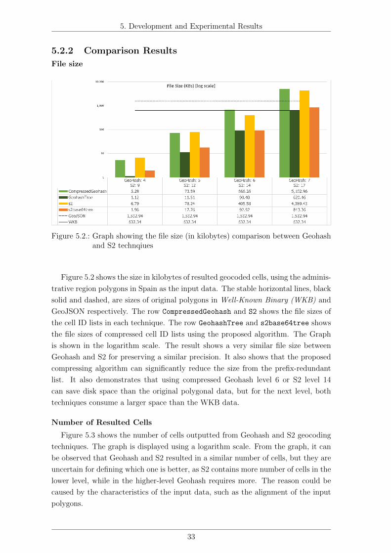
5.2. Graph showing the file size (in kilobytes) comparison between Geo-
hash and S2 technqiues . . . . . . . . . . . . . . . . . . . . . . . . . . 33
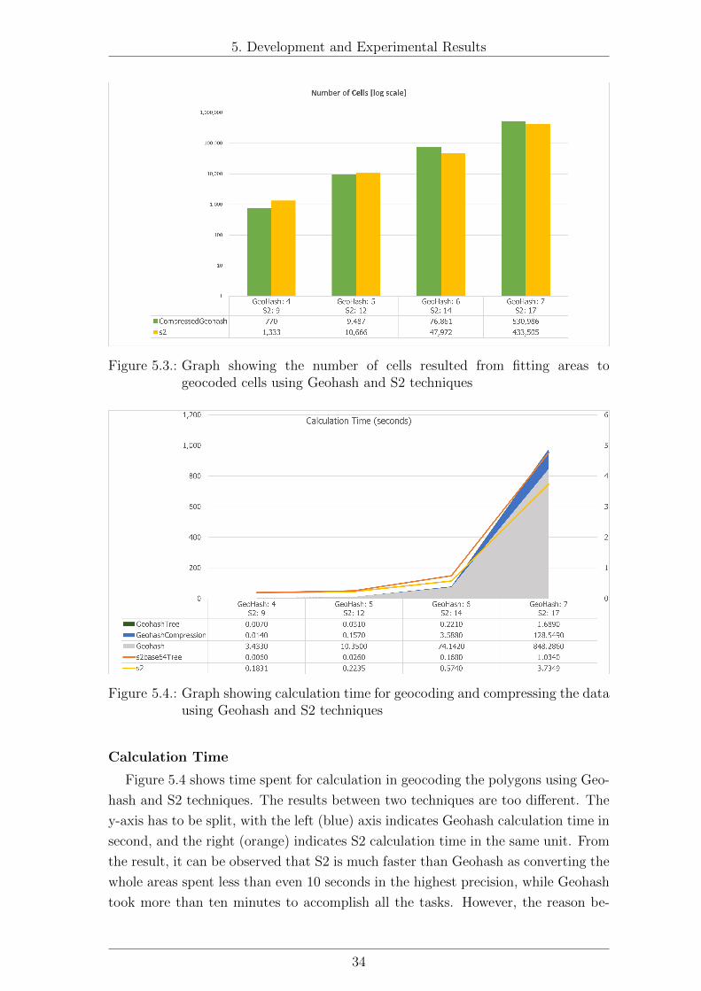
5.3. Graph showing the number of cells resulted from fitting areas to
geocoded cells using Geohash and S2 techniques . . . . . . . . . . . . 34
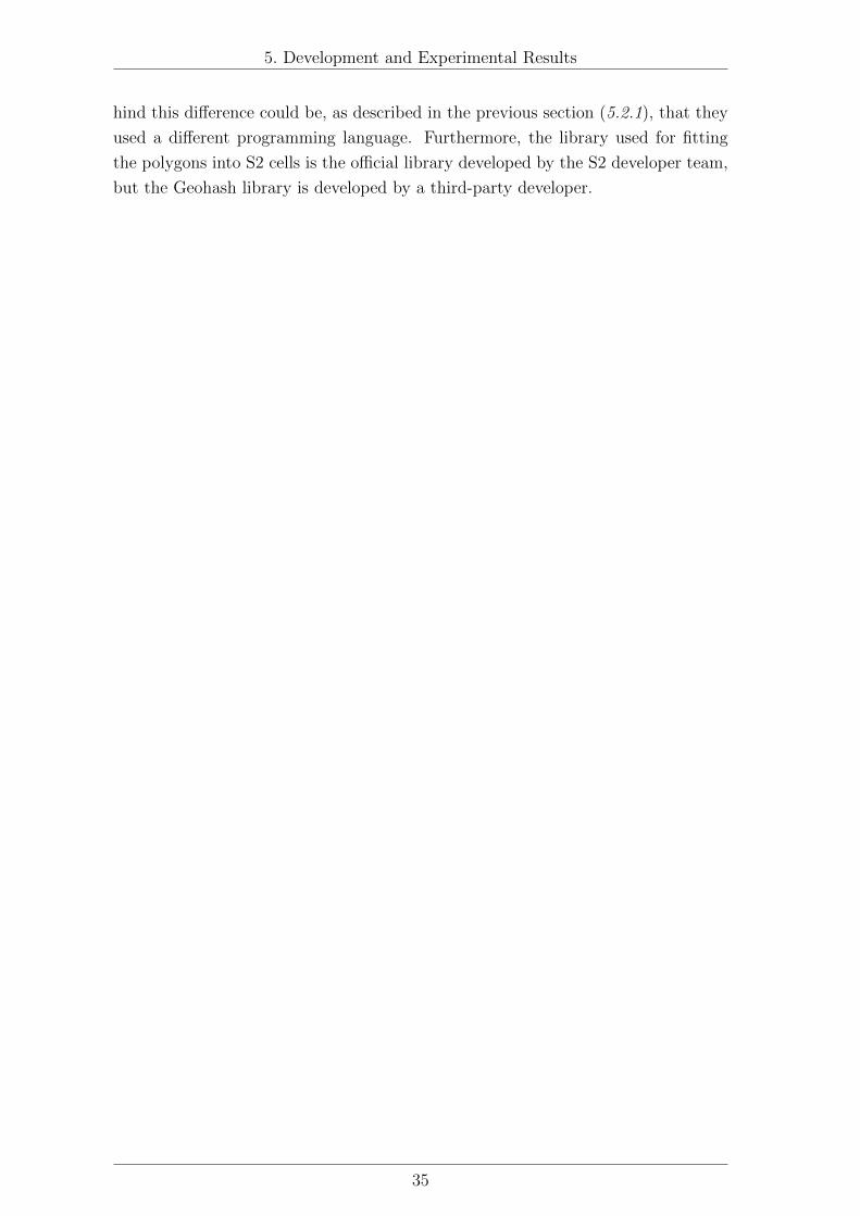
5.4. Graph showing calculation time for geocoding and compressing the
data using Geohash and S2 techniques . . . . . . . . . . . . . . . . . 34
5.5. The region divisions of data used in the simulation experiment . . . . 36
5.6. Gas consumption in contracts deployment . . . . . . . . . . . . . . . 37
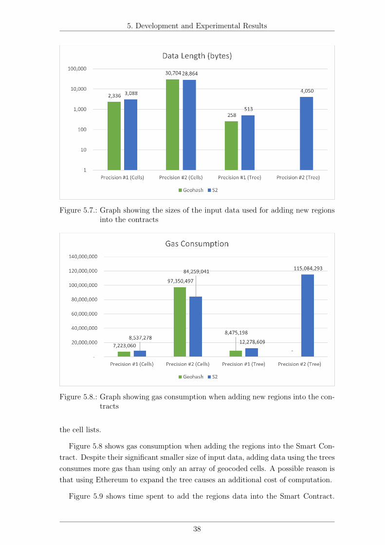
5.7. Graph showing the sizes of the input data used for adding new regions
into the contracts . . . . . . . . . . . . . . . . . . . . . . . . . . . . . 38
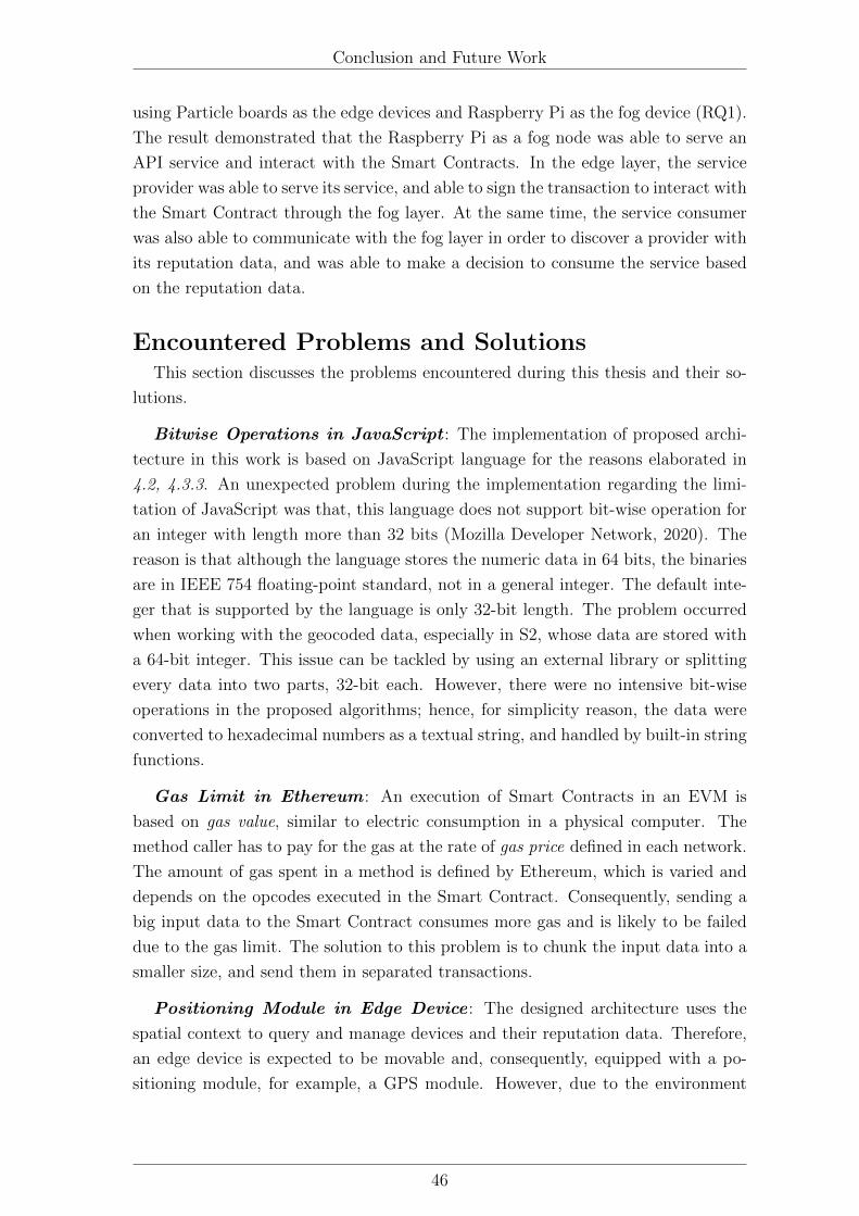
5.8. Graph showing gas consumption when adding new regions into the
contracts . . . . . . . . . . . . . . . . . . . . . . . . . . . . . . . . . . 38
5.9. Graph showing time spent when adding new regions into the contracts 39
5.10. Graph showing time spent when querying for a cell in the contracts
(in millisecond) . . . . . . . . . . . . . . . . . . . . . . . . . . . . . . 40
5.11. Graph showing time spent when mining a new block into the chain
(in second) . . . . . . . . . . . . . . . . . . . . . . . . . . . . . . . . . 41
V
Page 7
List of Figures
5.12. The instalment of test scenario: edge service provider, edge service
consumer, fog Raspberry Pi . . . . . . . . . . . . . . . . . . . . . . . 42
5.13. The service consumer status LED shows in green (trust) and orange
(not trust) . . . . . . . . . . . . . . . . . . . . . . . . . . . . . . . . . 43
VI
Page 8
List of Tables
5.1. Maximum error (cell size) of different levels in Geohash and S2 Geocod-
ing Techniques . . . . . . . . . . . . . . . . . . . . . . . . . . . . . . 32
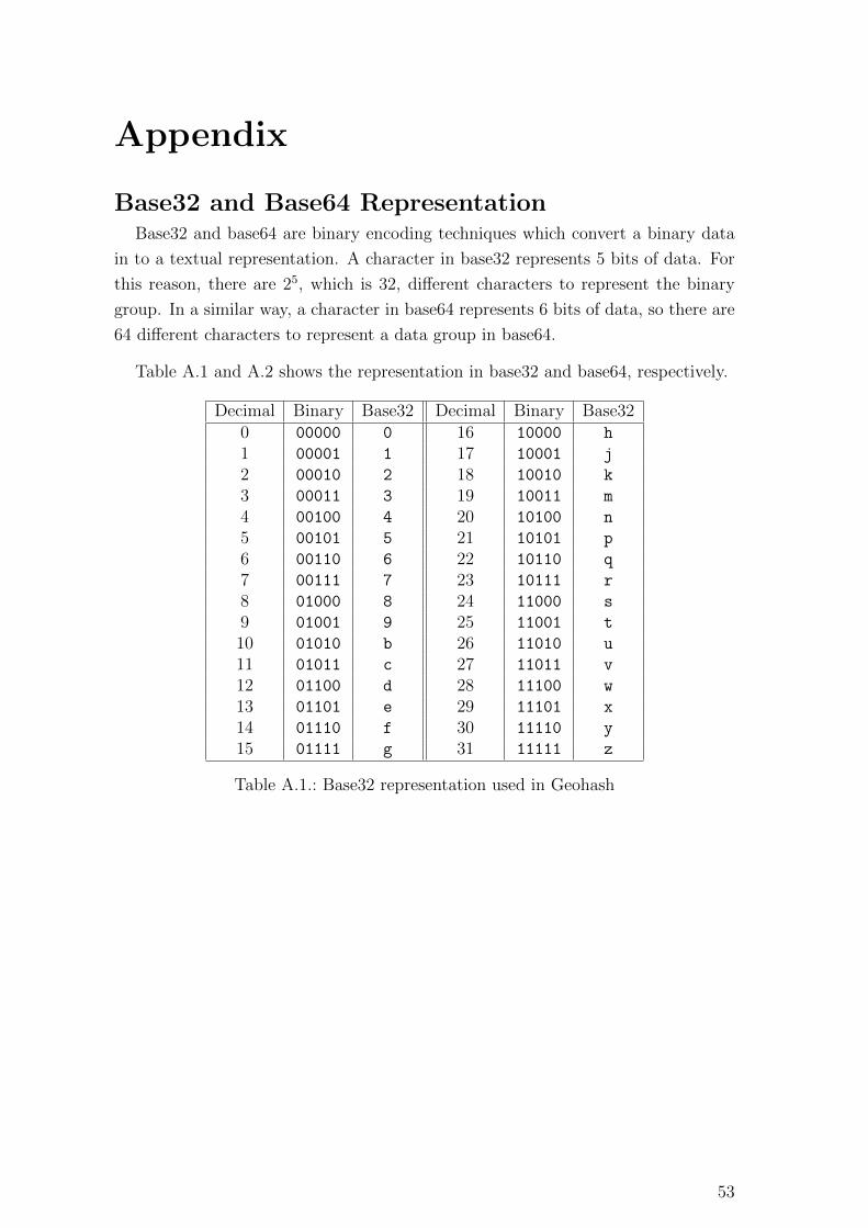
A.1. Base32 representation used in Geohash . . . . . . . . . . . . . . . . . 53
A.2. Base64 representation . . . . . . . . . . . . . . . . . . . . . . . . . . . 54
VII
Page 9
Acronym
Abbreviation Meaning
ABI Application Binary Interface
API Application Programming Interface
CPU Central Processing Unit
ECDSA Elliptic Curve Digital Signature Algorithm
EVM Ethereum Virtual Machine
GIScience Geographic Information Science
GPS Global Positioning System
GSM Global System for Mobile Communications
HTTP Hypertext Transfer Protocol
HTTPS Hypertext Transfer Protocol Secure
IEEE Institute of Electrical and Electronics Engineers
IoT Internet of Things
IP Internet Protocol
JSON JavaScript Object Notation
LAN Local Area Network
LED Light Emitting Diode
MQTT Message Queuing Telemetry Transport
NPM Node Package Manager
OOP Object-Oriented Programming
RFID Radio Frequency Identification
SDN Soft Defined Network
SIoT Social Internet of Things
SSH Secure Shell
WKB Well-Known Binary
UML Unified Modeling Language
URL Uniform Resource Locator
VPN Virtual Private Network
VIII
Page 10
1. Introduction
1.1 Context and MotivationInternet of Things or IoT has recently played an important role in connecting
physical objects into the internet network. The development of hardware capabilities
and communication technologies allow an object or a thing in our daily lives which is
equipped with sensors or actuators to connect to the internet network. This process
turns them into smart objects that can interact with users or with other devices in
order to observe a physical phenomenon and perform an interaction (Trilles et al.,
2015).
In human society, there might be a number of service providers offering services
that we need. When a person wants to interact or consume the service from another,
it is necessary to know how trustworthy they are, before one can decide to choose
and start an interaction. The way to know this trustworthiness can be based on the
experienced users’ recommendations, as well as from the evaluation based on service
quality. This is to guarantee that the service will satisfy users and will not cause
consequent failures.
In the same way, an IoT device can also communicate with each other in order
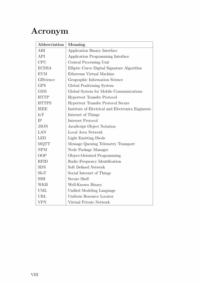
to consume or provide services. Figure 1.1 from Atzori et al. (2011)’s work shows
a comparison between the components of social networks in humans and digital ob-
jects. Trustworthiness management is a component that is relevant to the relation-
ship management in human social networks. To ensure that the provided services
are reliable and not leading to consequent failures, it is important to consume the
services from trusted providers. Despite the fact that trust is a subjective concept
and differs on each individual agent, it can be influenced by a quantity value such
as reputation index which is a social quantity property of an agent (Mui et al.,
2002). In consequence, it is necessary for an IoT system to have an architecture
that allows the management of device reputation indices in the system, so that the
devices that consume a service can use the value to decide whether they would trust
the provider before establishing a new connection.
Devices in an IoT system are usually distributed over the geographical space and
are able to move across different areas. The location of the devices can be a factor
that affects their trustworthiness (Lenzini et al., 2008). For this reason, this master
thesis will use this location component to build a reputation management system
architecture to manage IoT relationships. In other words, it will include the spatial
context of devices in order to establish the reputation values.
Another related technology is cloud-fog-edge architecture , which is a hier-
1
Page 11
1. Introduction
Figure 1.1.: The components of social networks in human (left) and machines (right)(Atzori et al., 2011)
archical architecture in the IoT. It divides the system into three layers which are
cloud, fog, and edge layer. While the traditional cloud and edge layer were designed
for heavy processing and low-level computation respectively, the fog layer was later
proposed by Cisco to be an intermediate layer between these two layers (Cisco,
2015). The capacity of a fog hardware is generally lower than the one in the cloud,
but greater than edge devices enough so it can perform more complex calculations.
Hence, not all unnecessary computations have to be loaded in only cloud layer.
Moreover, the instalment of fog devices is also compromised in the extend between
cloud and edge layers. They are therefore generally geographically distributed, which
are ideal to cover the location-based reputation management system.
The last related concept is decentralisation . Due to the existence of fog layer,
the intermediate devices are now distributed and not all computations need to be
in the cloud layer. Blockchain is a technology that allows data to be stored in
a distributed way. All nodes in a Blockchain network will share and possess the
same data which are formed in blocks chronologically linked to each other like a
chain. The chain is distributed over the network which makes the system to be
transparent and fault-tolerant (Golosova and Romanovs, 2018). The Blockchain
technology relies on hashing and consensus algorithms to confirm that all nodes in
the network are having the same valid data, and it is not easy to tamper the chain.
The implementation of the Blockchain are well-known in cryptocurrency , such as
Bitcoin and Ethereum. But in the Ethereum, besides storing the money transactions
it also allows Smart Contract which is an executable programme to be stored and
callable from the Blockchain network. In the other words, the Ethereum Blockchain
network acts like a virtual machine that has the advantages of decentralisation in
2
Page 12
1. Introduction
Blockchain. Thus, this thesis proposes to adopt the Ethereum Smart Contract in the
fog layer to create a decentralised application that is able to manage the reputation
indices of an IoT system.
However, even the decentralised applications can execute any programming like
a real computer does, but the characteristics of the Blockchain limit the ability
of complex calculations in Smart Contracts. Geometric spatial objects and their
calculation which are related to complex algorithms and complicated data structures
could cost an expensive computation in the Blockchain network. For this reason,
this thesis will use spatial indexing techniques in the implementation to study and
challenge the possibility of manipulating spatial data in the Blockchain. There are
two hierarchical spatial indexing techniques being studied in this thesis. The first one
is Geohash which is an indexing technique invented by Gustavo Niemeyer (Balkic
et al., 2012). And the second one is S2 which was invented by Google engineers1. Both techniques share the same hierarchical characteristics despite their different
algorithms behind. This thesis will therefore study the characteristics of these two
techniques and compare their usage in the decentralised applications.
1.2 Aims and ObjectivesThe main objective of this work is to propose a decentralised IoT architecture
which allows the location-based management of device services and their reputation
values using Blockchain.
To accomplish the main objective, this work will propose an IoT architecture
based on cloud-fog-edge structure, and decentralise the management system in the
fog layer using the Ethereum Smart Contract. Secondly, it will study and compare
two spatial indexing techniques of Geohash and S2 which are used to represent the
geographical data in the system, as well as implement and analyse their usage in
the Smart Contracts. Finally, it will simulate the architecture by implementing and
deploying the system in the real IoT devices.
1.3 Research Questions1. Is it possible to implement a decentralised area-based reputation management
system of an IoT system in the fog layer using Blockchain?
2. Is it possible to manipulate spatial data in a Blockchain network based on
spatial indexing techniques?
3. Comparing Geohash and S2 geocoding techniques, which one does perform
better in the proposed architecture, regarding speed, size, and suitability?
1https://github.com/google/s2geometry
3
Page 13
1. Introduction
1.4 Document StructureThis thesis report is divided into five chapters. The first chapter, Introduction,
which is the current chapter, explains the motivation behind this work, the goals of
the study, and the research questions. Next chapter, Background, explains the re-
lated technologies and techniques. There are three main topics related to this work,
which are Internet of Things (IoT), Blockchain and Spatial Indexing. The third
chapter, Related Works, explores the literature of existing works that are related
to the proposed architecture, as well as their technologies. Fourthly, Methodology,
explains the implementation design of this work. It starts with the System Architec-
ture by introducing the whole picture of the proposed architecture, followed by the
Implementation and Development which explains the tools and technologies used to
develop the proposed architecture, and lastly, the Experiment Design elaborates the
experimental procedures to test and evaluate the architecture. After that, the fifth
chapter of Development and Experimental Results shows the development
and experiment results of the architecture. Followed by Conclusion and Future
Work, the last section which concludes the work and summarises experiment re-
sults, as well as suggests for the future development. Finally, in the final part of
the report, Appendix elaborates and explains related technologies and the data
structures that could not be included in the previous chapters.
4
Page 14
2. Background
2.1 Internet of Things (IoT)The term Internet of Things or IoT refers to the combination between net-
work (internet), and physical objects (things). It was firstly coined in 1999 by Kevin
Ashton in his work of using Radio Frequency Identification or RFID in a supply chain
system (Ashton, 2009). The IoT devices rely on wireless communication technolo-
gies to connect them to the network. Such technologies that allow the development
of IoT are for instance: Bluetooth, RFID, Wi-Fi or GSM. As the technologies in
wireless communication are continuously being developed and advanced, it allows
IoT community to expand and grow significantly (Gubbi et al., 2013).
2.1.1 Trust and Reputation System in IoT
Social Internet of Things or SIoT is an integrated concept between IoT and
human social networking. The idea is that the things in an IoT system can discover
the other devices which provide the needed services, establish a relationship and
communicate with them (Atzori et al., 2012). As humans do in their social life,
when a person wants to know someone, or use a business service, they must know
how reliable it is. Also in the computer systems, when a device wants to use a
service from the other devices, before establishing a connection with them, it should
know whether the source is trustworthy in order to avoid problems or failures due
to unexpected behaviours.
The concept of trust is very subjective to each individual. Mui et al. (2002)’s
study says that trust is a subjective expectation that one agent has toward an-
other one. It is used for expecting their future behaviours based on the encountered
history. Artz and Gil (2007) divides the obtainment of trust in a computer system
into two categories: policy-based trust and reputation-based trust. A policy-based
trust is centralised and the decision criteria are based on a third party. The second
one is based on reputation , which is a quantitative property derived by observed
actions or behaviours in the past of one agent. Hence, the non-centralised charac-
teristic of the reputation-based trust allows an individual to subjectively decide its
trustworthiness.
2.1.2 Cloud-Fog-Edge Architecture
As the IoT is growing and its related technologies are moving forward, an IoT
system could expand to a larger number of devices and connected sensors. This
raised consequent issues such as heavy processing and big data storage in the cloud
layer or exceeding bandwidth in the network. To tackle the problem, Cisco company
5
Page 15
2. Background
proposed a solution by adding an intermediate layer between the cloud and end-
device (edge) layers, called the fog layer (Cisco, 2015).
In a general cloud-fog-edge architecture , the edge layer is the most bottom
layer where the end-devices are. The devices in this layer are simplest and have less
computation ability, connected to sensors or actuators in order to observe a physical
phenomena or to have an interaction. The end-devices are generally in a larger
amount, and they should not perform any complex computation because they have
limitations regarding hardware specification, memory and power consumption.
Secondly, the fog layer is the intermediate layer. The devices in this layer have
more computation ability and can handle preliminary data processing as well as to
store sensory data before forwarding them to the cloud layer. In opposite direction,
the fog layer can also be a middle party that passes commands or messages from
the cloud layer to the edge layer. Because the fog layer can also be geographically
distributed, it can organise the edge devices in its responsible area.
The last one is the cloud layer , which is the topmost layer in the architecture
and is in charge of processing final data, managing the whole system, and storing
the sensory data. A cloud device is supposed to be physically static, and located
in a data centre or a dedicated place. The device itself can be either a dedicated
server where the organisation administrator has responsibility of administration and
maintenance. Or it can be a cloud service in a form of platform-as-a-service (PaaS) or
software-as-a-service (SaaS) which is provided by an external cloud service provider
such as Microsoft Azure, Amazon Web Service (AWS), or Google Cloud.
2.2 BlockchainBlockchain is a technology to store computer data in a distributed and decen-
tralised way. A Blockchain network is consisted of a number of blocks . In a block
there are transactions to store the data in the network. Blocks and transactions
are uniquely identified by using a cryptography hashing algorithm. The identifier
hashes of the blocks are used to link each other in a chronological linear sequence
like a chain, which is the reason behind its name.
2.2.1 Fundamental of Blockchain
Blockchain was originally mentioned by Nakamoto (2008) (whose name is be-
lieved to be a pseudonym). It proposed an electronic cash system that can store the
transactions of ledgers in a decentralised way by using peer-to-peer communication.
A Blockchain network has a number of blocks which are linked to each other in
a chronological sequence. As Blockchain was originally developed for storing money
movements in an electronic currency called Bitcoin, the data in each block are a set
6
Page 16
2. Background
of money transactions . A Blockchain node collects transactions from its clients
and pack them into one block. Then, the block is pushed to the end of the chain.
The node that has pushed the block will then broadcast the change to the other
nodes in the same network to update the data. Finally, the other nodes verify the
change before updating their own chain.
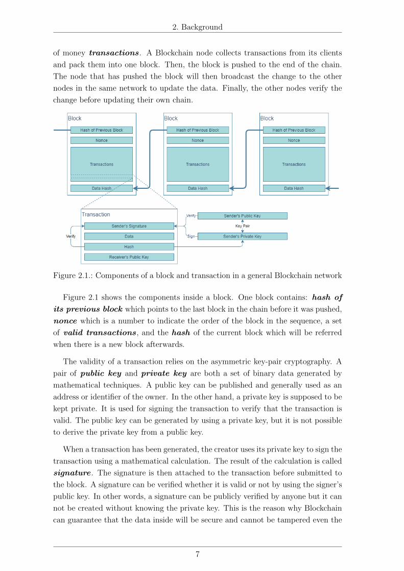
Figure 2.1.: Components of a block and transaction in a general Blockchain network
Figure 2.1 shows the components inside a block. One block contains: hash of
its previous block which points to the last block in the chain before it was pushed,
nonce which is a number to indicate the order of the block in the sequence, a set
of valid transactions , and the hash of the current block which will be referred
when there is a new block afterwards.
The validity of a transaction relies on the asymmetric key-pair cryptography. A
pair of public key and private key are both a set of binary data generated by
mathematical techniques. A public key can be published and generally used as an
address or identifier of the owner. In the other hand, a private key is supposed to be
kept private. It is used for signing the transaction to verify that the transaction is
valid. The public key can be generated by using a private key, but it is not possible
to derive the private key from a public key.
When a transaction has been generated, the creator uses its private key to sign the
transaction using a mathematical calculation. The result of the calculation is called
signature . The signature is then attached to the transaction before submitted to
the block. A signature can be verified whether it is valid or not by using the signer’s
public key. In other words, a signature can be publicly verified by anyone but it can
not be created without knowing the private key. This is the reason why Blockchain
can guarantee that the data inside will be secure and cannot be tampered even the
7
Page 17
2. Background
data are visible and distributed across the network.
The propagation of the data in a network becomes a problem when multiple
peers want to push a new block at the same time, because the network should
consider which chain from which peer node is valid and should be accepted in the
chain. This kind of problem is also known as Byzantine Generals Problem (Lamport
et al., 1982). In Blockchain, the consensus algorithm is used to tackle the issue.
There are a number of different consensus algorithms that are used in different
Blockchain implementations. For example, Bitcoin and Ethereum uses Proof of
Work consensus algorithm. The Proof of Work gives a difficult mathematical
challenge based on the nonce value in the latest block. The first node that can
solve the problem has the right to push the block into the chain. The process of
calculating the mathematical problem is also called mining. The other examples of
consensus algorithms are Proof of Stake which randomly select one node from
the candidates using steak or wealth in the system as a random bias, or Proof of
Authority which gives the right to an authorised node to add the block to the
chain (Mingxiao et al., 2017).
2.2.2 Ethereum and Smart Contracts
Ethereum is a Blockchain implementation. Similarly to Bitcoin, Ethereum
blockchain also has its cryptocurrency called Ether . The difference that makes
Ethereum to be outstanding among developers is that Ethereum allows a block to
store executable programmes. This kind of applications is called Smart Contract .
A Smart Contract allows the execution and the storage of the programme stage to
be done in a distributed and decentralised way. The operation codes (opcode) in
the Smart Contract were designed to be Turing complete, which means that it can
execute any programme algorithms that the actual computers can perform (Buterin
et al., 2014).
Similar to the other Blockchain implementations, all nodes in Ethereum network
contains the same transactions data, including Smart Contracts and their contract
states. This concept is like having a computer whose instances are distributed over
the Blockchain network. When a contract method is called, the node will add the
method calling transaction into the chain. The transaction can be interpreted and
executed to update the contract state. When the transaction is propagated over the
network, the other nodes will also update their contract state in the same way. This
distributed machine is called Ethereum Virtual Machine (EVM).
Figure 2.2 shows the workflow of an Ethereum Smart Contract. The top level
programming language to write a Smart Contract can be either Solidity or Vyper ,
which has the similar syntax to JavaScript and Python respectively. After that,
the programming codes are compiled into Ethereum opcode binaries. An opcode
8
Page 18
2. Background
Figure 2.2.: An example flow of contract creation and function calling in EthereumSmart Contract
indicates a computational operation of the EVM like an opcode in a computer
programme. These binaries data are then embedded into a transaction in a block
and pushed into the chain. The figure 2.2 also shows that calling method which
changes the contract state (altering the variable value in the contract) needs to be
submitted as another transaction in another block. However, if the method is read-
only (returns the contract state value without updating it), it can be called instantly
without submitting as another transaction.
Calling a method in the Smart Contracts needs to be payed by its cryptocur-
rency. The price of a method calling is determined by gas spent in the calculation.
The concept of gas is similar to the electric consumption in a physical computer.
Each opcode in a Smart Contract spends a different amount of gas determined by
Ethereum1. The maximum amount of gas is limited by the Ethereum network. For
this reason, a method which has too many operations, especially iterations, is likely
to cause an out of gas error from the Ethereum network.
2.3 Spatial IndexingA computer processes and handles data in binary. Therefore, the data that are
not based on binary integer require more complicated data structures and different
1Ethereum gas per opcode: https://docs.google.com/spreadsheets/d/1m89CVujrQe5LAFJ8-YAUCcNK950dUzMQPMJBxRtGCqs
9
Page 19
2. Background
standards to work with, for instance, decimal (floating) number, text, picture, sound,
as well as geospatial data. Querying and accessing these types of data can be
improved in performance and efficiency by using indexing techniques. Indexing
technique constructs the desired data to be a certain kind of search-able keywords.
When a user wants to query for the data, it can use a lookup table containing the
sorted indices to quickly look for the position where the desired data are located.
However, indexing the geographical data is more complicated as it is multidi-
mensional and generally related to Euclidean space (Lu and Ooi, 1993). There are
different ways to index the geospatial data, for example, R-Tree which is based on
a binary search tree for range query of destination spatial object (Guttman, 1984).
This thesis will focus on the geocoding-based indexing techniques to store and query
for the spatial data objects in the Blockchain.
Geocoding is the conversion of a geospatial object into another kind of interpre-
tation. Some geocoding techniques aim to ease human readability, postal address for
example. In the other hand, some of them aim to ease the readability and indexing
in machine as the geocoded value is resulted in a binary integer, such as Geohash
and S2 , which are going to be studied in this thesis. However, geocoding techniques
are not two-way compatible. In other words, the geocoded information cannot be
reverted to the exact same geospatial object, but only to a similar one (Moussalli
et al., 2015). Nevertheless, loss of accuracy is tolerable in this work, as its aim is not
to store the exact geospatial data, but is to use them as an additional contextual
information of the reputation management in an IoT system.
2.3.1 Geohash
Geohash is a hierarchical geocoding technique. As it is hierarchical, Geohash
representation does not have a fixed length, but the longer it is, the more precise
geographical location it can describe. A Geohash defines a location by storing binary
bits of longitude in the odd positions, and latitude in the even positions (when the
first position starts with 1). However, it is more common to represent this group of
binary bits into a textual representation, by grouping them into five bits per group
and use base32 representation to textualise the data (Suwardi et al., 2015).
(Appendix Base32 and Base64 Representation)
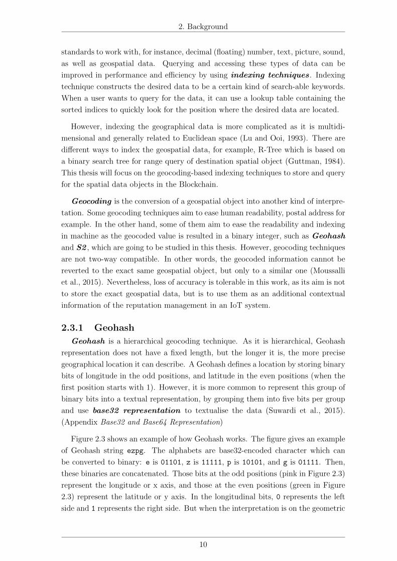
Figure 2.3 shows an example of how Geohash works. The figure gives an example
of Geohash string ezpg. The alphabets are base32-encoded character which can
be converted to binary: e is 01101, z is 11111, p is 10101, and g is 01111. Then,
these binaries are concatenated. Those bits at the odd positions (pink in Figure 2.3)
represent the longitude or x axis, and those at the even positions (green in Figure
2.3) represent the latitude or y axis. In the longitudinal bits, 0 represents the left
side and 1 represents the right side. But when the interpretation is on the geometric
10
Page 20
2. Background
Figure 2.3.: Example of the interpretation of a Geohash string into the geographicalobject
earth, it will start by taking the longitude 0° as the middle point. When the bit is
0 it will travel to the minus side of the middle point (-180° to 0°), while in the case
of 1 it will travel to the plus side of the middle point (0° to 180°). For the next bit
position, the new middle point will be calculated, and takes the same step over and
over until the end of the sequence. Similarly for the latitudinal bits, 0 represents
the lower side from the middle point and 1 represents the upper side, when the first
middle point is the equator.
The Geohash then preserves the hierarchical property, as when it is represented
by a less number of bits, the area (or the error) will be larger and is more difficult to
11
Page 21
2. Background
define a point in the area. But the more bits it gains, the smaller the area shrinks.
For this reason, two Geohashes having a mutual prefix means that they are located
in the same cell at the upper level.
2.3.2 S2
S2 is another hierarchical geocoding technique similar to Geohash. It is repre-
sented by an integer with a maximum of 64 bits in length. Because it is hierarchical,
like Geohash, the length of the representation can be reduced, but there will be a
loss of its accuracy as the represented area will be bigger (Victor and Zickau, 2018).
Figure 2.4.: Example of interpretation of S2 cells
One difference between Geohash and S2 is that S2 cells are based on the Hilbert
space-filling curve, which is a line that travels through all the cells in a tabular space
12
Page 22
2. Background
without making any loops.
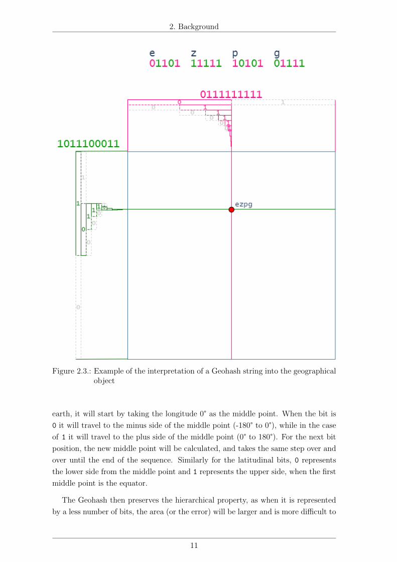
Figure 2.4 shows the characteristics and the interpretation of S2. The length of
an S2 representation can be 64 bits in maximum, but it can be trimmed to the
desired level to reduce space consumption. The end of S2 is determined by the last
bit 1 that is followed by 0s until the end of the data length. Those bits before that
are significant for calculation and cannot be cut, otherwise, the precision will be
lost. An area represented in S2 is called cell , which is the term that will be used in
this thesis to refer a geocoded area in either Geohash or S2.
As S2 uses a cube to fit the earth sphere and project the location to each face of
the cube, the first 3 bits of an S2 cell are preserved for determining in which face the
cell is falling in2 (from 000 for the first face, until 101 for the sixth face). The next
set of the binary data represents the linear position on the Hilbert curve. One cell
position in the Hilbert curve contains 4 cells in the next level. Hence, every level
increment requires 2 more bits.
The example in Figure 2.4 shows that 100001101101000100 contains 18 bits,
which means the cell is located in 138,053rd region in level-9 of the Hilbert curve,
out of all 262,144 regions (which is 49). The figure also demonstrates that, decreasing
level of the Hilbert curve, the cell still covers the same region but in a bigger area.
This also implies that when two cells have a mutual prefix, they are located in the
same cell of the upper level, which is the same property that Geohash also has.
2https://s2geometry.io/resources/earthcube
13
Page 23
3. Related Works
Decentralisation of the reputation management system in an IoT system based
on agent geographical locations is a relative new topic. For this reason, there are
no many direct related works. This section divides the reviews of the literature into
different related categories, which are Trust and Reputation Management System,
Blockchain and IoT, and Spatial Indexing.
3.1 Trust and Reputation Management SystemThere are several related works regarding an IoT system architecture to manage
reputation values and trusts. In Chen et al. (2019)’s work, the architecture divides
the reputation management into five layers: reputation management layer, organi-
sation layer, SDN control layer, node layer and object layer. Users requests for an
operation of the IoT device through the organisation layer, which is the middle way
between the reputation management centre and the end nodes. The organisation
layer decides whether the requested node is trustworthy before executing the action.
Devices in this work do not execute their actions by themselves without a decision
from the organisation layer. Guo et al. (2019) also purposed an interesting scenario
of moving IoT devices and an architecture to manage their trust values. The work is
based on a scenario of sharing air quality data, whose trust are evaluated by user’s
experience towards another target user in a different area. The consumer chooses
the most trustworthy data provider and decide whether the air quality in the target
area is satisfying, so that they can move into the area. The work is not based on
the reputation value, which is a common expectation value towards one agent in
the system, but it is based on a subjective trust, which is a one-to-one relationship
between each device. Furthermore, the management system is centralised in the
cloud as all trust values of each device relationship are stored there, therefore the
dependency of calculation and storage of the values are depend on the cloud layer.
There were also works that tried to decentralise the trust management system
as well. Debe et al. (2019)’s work proposed an architecture of a decentralised rep-
utation management system in an Ethereum network by using Smart Contract. In
this work, end devices are in charge of evaluating the fog devices and store their
reputation values in the Smart Contract. The work is a good example of designing
an architecture of reputation management using Smart Contract in IoT. However,
the reputation value in this work is subjected to fog devices, not to edge devices,
which serves different propose from this thesis. Additionally, Kouicem et al. (2018)
has proposed a cloud-fog-edge-based architecture to manage trust values of devices
in the system. The Blockchain network is implemented in the fog layer. In this
14
Page 24
3. Related Works
architecture, an end device generates the reputation information of another device
in a transaction, and sign it before submitting to the Blockchain network. The
values are stored in the Blockchain and, therefore, they are shared across different
fog nodes in different areas. However, the reputation value itself is the same even
the device has moved to a different region. A spatial context is not considered for
managing the reputation values.
3.2 Blockchain and IoTIn the previous section (Trust and Reputation Management System), there have
been already mentioned some works using blockchain to serve trust management
purpose: Debe et al. (2019)’s uses Smart Contract in Ethereum to store reputation
values of fog devices, and Kouicem et al. (2018) uses Blockchain in fog layer to store
reputation of devices. This section explores more of the Blockchain usage in IoT
systems regardless of relevance to trust management system.
Huh et al. (2017) implemented the Ethereum Smart Contract in an IoT system to
manage devices and control their behaviour policies. The work shows that using of
Smart Contract allows the system to configure device rules and able to control them
in a distributed way. Fernando et al. (2019)’s work also showed the possibility of
deploying Blockchain network in IoT devices by using Raspberry Pi as a node. This
implies that IoT devices, comparing to modern computer, smaller in size, better in
mobility, are powerful enough to run necessary computations for being a Blockchain
node.
3.3 Spatial IndexingIn the fundamental level, computer recognises all the digital data as binary in-
tegers, which means more complex data requires these binaries to be formed in a
more complicated structure and have proper algorithms to work with them. This
applies to the geospatial data. Digitalised lines, points or polygons in a space re-
quire binary representation. It also needs indexing for speeding up the query. This
section explores the works that use spatial indexing techniques and their usage in
Blockchain.
Deiotte and Valley (2017) compared different techniques of geocoding between
raw geographical object (coordinates), Z-Order space-filling curve (Geohash), and
Hilbert space-filling curve, in terms of computation, efficiency, and utility. The
study showed that geocoding using the Hilbert curve performed better in most of
the aspects. Victor and Zickau (2018) used Geohash and S2 to fit a desired region.
The resulted cells were used for being a geofence, stored in a Smart Contract. The
work demonstrated the feasibility of handling spatial data in Smart Contracts. They
finally concluded that in their work S2 has a better performance than Geohash.
15
Page 25
4. Methodology
This chapter is divided into three main sections. Firstly, System Architecture
proposes the architecture overview and its component in the system. Secondly, Im-
plementation and Development describes tools and languages used for develop-
ing the proposed architecture. The last part of this chapter, Experiment Design
elaborates how the experimental procedures will be held and how to evaluate the
results.
4.1 System Architecture
4.1.1 Overall Architecture
In this work, the reputation management system of IoT devices is based on cloud-
fog-edge architecture. Each device in the fog layer is a node in the Ethereum
Blockchain network. In practice, the Ethereum network can be either public or
private network. However, in this work we encourage the private one because the
management system is aimed to be decentralised in an IoT system, not to be a
public access for anybody. The Smart Contracts deployed in the fog layer can store
and manipulate edge devices, their services information, and geographical data of
the associated regions.
Figure 4.1.: Overall architecture of the proposed reputation management system
16
Page 26
4. Methodology
Cloud layer
Cloud layer is generally in charge of storing and analysing data from edge sensors,
as well as controlling, visualising and interacting with users. However, in this work,
because the management system is expected to be implemented in the fog layer,
and the sensory data manipulation is not a protagonist in this thesis, so there will
be less mentioning about this layer. In a practical implementation of the proposed
architecture, cloud layer can serve an API for system administrators to control fog
nodes in the layer.
Fog layer
Fog layer contains a number of devices which can be either geographically dis-
tributed or not. These fog devices connect to each other and form an Ethereum
Blockchain network to serve the Smart Contracts for managing reputation indices
and to serve the APIs to interact with the contracts. One fog device can be asso-
ciated to a single or multiple regions. However, it is not necessary because a fog
device can be a Blockchain node without being associated to any regions. For ex-
ample from Figure 4.1, fog V is not associated to any region, while fog W, X, Y, Z
are associated to the region W, X, Y, Z respectively.
Edge layer
A device in this layer is equipped with sensors or actuators, and are designed to
communicate with other devices in order to consume the services (dashed-line 1 from
Figure 4.1). The service consumption between devices will be based on their trust ,
which they can decide whether to trust a service provider by using the reputation
index stored in the Smart Contracts from the fog layer. Therefore, an edge device
need to communicate with the fog layer to discover other devices in the area that
provide needed services, and to query the reputation data of those providers.
Furthermore, devices in the proposed system are assumed to be movable and can
be displaced across the different areas. Hence, when a device entered another area
it should have a different reputation value because it is not recognised in the region.
For example, from Figure 4.1, device C can move from region Y to X (arrow 2), but
once it has moved, device D which is its consumer should not anymore recognise its
reputation. And to consume the service it should establish a new connection with
another device in the area that it can secondly trust.
4.1.2 Scenario and Interaction Flows
To achieve the architecture in Figure 4.1 from the last section (4.1.1). This sec-
tion elaborates the usage context of the architecture by designing interaction flows
between each role in the system. These flows will help to understand the function-
alities of different components in the system, which are important for development
17
Page 27
4. Methodology
design of programming classes and functions in the implementation section.
The location-based reputation management system plays a role in the IoT system
when an end device has moved, or has requested to establish a connection with
another device. Therefore, this section divides the related interaction flows into
three categories, which are 1) region management flow which happens when there
is a fog layer wants to associate itself to a geographical region in the system, 2) edge
device mobility flow which happens when an edge device has moved within the same
or between different regions, and 3) reputation management flow which happens
when an edge device wants to consume a service from another device.
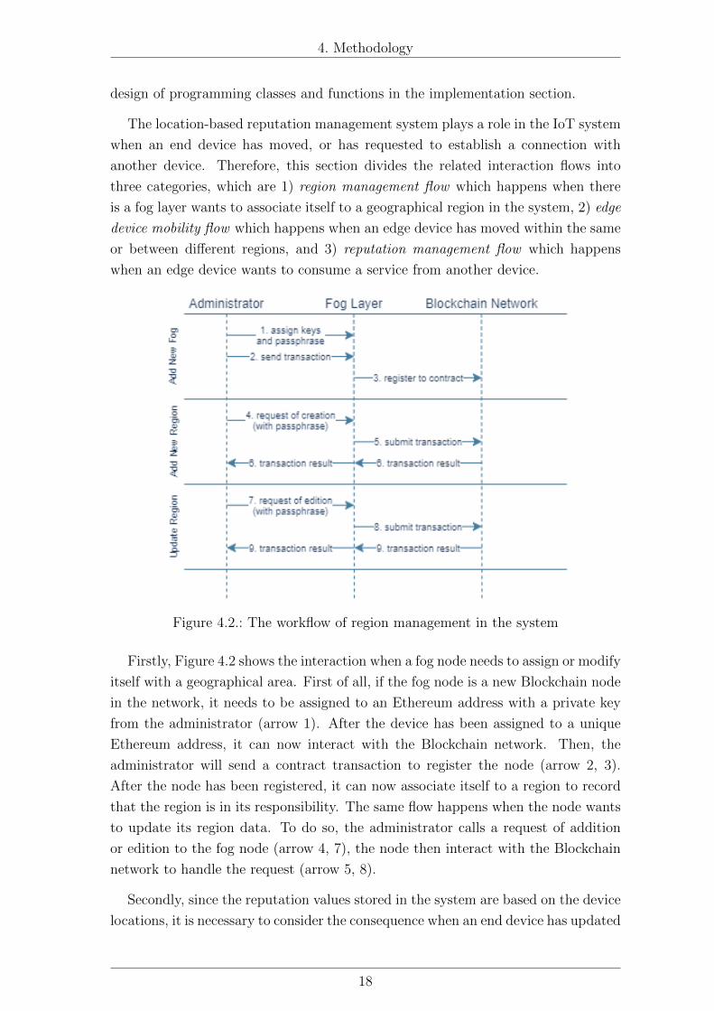
Figure 4.2.: The workflow of region management in the system
Firstly, Figure 4.2 shows the interaction when a fog node needs to assign or modify
itself with a geographical area. First of all, if the fog node is a new Blockchain node
in the network, it needs to be assigned to an Ethereum address with a private key
from the administrator (arrow 1). After the device has been assigned to a unique
Ethereum address, it can now interact with the Blockchain network. Then, the
administrator will send a contract transaction to register the node (arrow 2, 3).
After the node has been registered, it can now associate itself to a region to record
that the region is in its responsibility. The same flow happens when the node wants
to update its region data. To do so, the administrator calls a request of addition
or edition to the fog node (arrow 4, 7), the node then interact with the Blockchain
network to handle the request (arrow 5, 8).
Secondly, since the reputation values stored in the system are based on the device
locations, it is necessary to consider the consequence when an end device has updated
18
Page 28
4. Methodology
Figure 4.3.: The workflow of edge device mobility
its location. Figure 4.3 shows the flow of the action. As same as the fog layer, a
device in the edge layer also needs its own identity in the Blockchain network so
that it can interact with the Smart Contracts. Hence, it is necessary to register a
device to the Smart Contracts when it has been added to the system. To do so,
the device owner must assign a unique Ethereum address and its private key to
the device (arrow 1). Then, the device sends a contract transaction for registering.
However, due to the hardware limitations of those devices in the edge layer, it will
be too big for them to store the contracts interface and be a Blockchain node. For
this reason, the interaction between the edge devices and the Smart Contracts will
be done through the fog layer. After the fog layer receives a registration request
from an edge device (arrow 4), it generates a raw unsigned transaction and gives
it back to the device (arrow 5). The fog layer cannot sign the transaction for the
edge device because it does not know the private key. The edge device signs the
transaction (arrow 6) and send the signature back to fog layer (arrow 7). The fog
layer submits the transaction to the Blockchain network (arrow 8).
19
Page 29
4. Methodology
After the edge device has been registered, it can be referred in the Smart Con-
tracts by using its Ethereum address. Then, when the device has moved, it sends
the updated location to the fog layer to check for the update if needed (arrow 11,
Figure 4.3). The fog layer checks with the Smart Contract whether it is necessary
to update the device location data (arrow 12), in case of yes, it returns an unsigned
transaction back to the device (arrow 14). The device signs the transaction and
return the signature to the fog layer (arrow 15, 16).
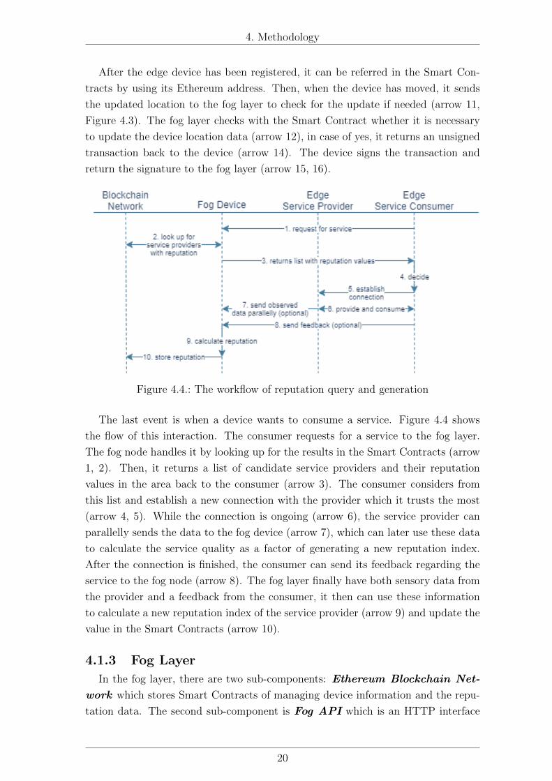
Figure 4.4.: The workflow of reputation query and generation
The last event is when a device wants to consume a service. Figure 4.4 shows
the flow of this interaction. The consumer requests for a service to the fog layer.
The fog node handles it by looking up for the results in the Smart Contracts (arrow
1, 2). Then, it returns a list of candidate service providers and their reputation
values in the area back to the consumer (arrow 3). The consumer considers from
this list and establish a new connection with the provider which it trusts the most
(arrow 4, 5). While the connection is ongoing (arrow 6), the service provider can
parallelly sends the data to the fog device (arrow 7), which can later use these data
to calculate the service quality as a factor of generating a new reputation index.
After the connection is finished, the consumer can send its feedback regarding the
service to the fog node (arrow 8). The fog layer finally have both sensory data from
the provider and a feedback from the consumer, it then can use these information
to calculate a new reputation index of the service provider (arrow 9) and update the
value in the Smart Contracts (arrow 10).
4.1.3 Fog Layer
In the fog layer, there are two sub-components: Ethereum Blockchain Net-
work which stores Smart Contracts of managing device information and the repu-
tation data. The second sub-component is Fog API which is an HTTP interface
20
Page 30
4. Methodology
for communication with the administrator users and edge devices.
4.1.3.1. Ethereum Smart Contracts
Figure 4.5.: Class diagram of the Smart Contracts
A Smart Contract in the Ethereum Blockchain network can be written in Solid-
ity programming language. The syntax of Solidity allows an object-oriented way
of programming. Hence, the structure of a Smart Contract can be described using
a diagram similar to programming in other OOP languages such as C# or Java.
Nevertheless, the computation is slightly different comparing to a traditional pro-
gramming language as there are some points needed to concern when doing Smart
Contracts programming, such as:
• Methods in Solidity can return more than one values.
• Decimal number: float or double, is not fully supported in Solidity (Ethereum,
2020), so integer or big integer is more encouraged.
21
Page 31
4. Methodology
• Similarly, strings are also not fully supported in Solidity. For this reason,
manipulating and storing textual data should be done in binary level.
• When sending a contract method transaction, the Smart Contract always
knows who is the transaction sender. Therefore, it is not necessary to de-
fine a caller in the method parameters.
Figure 4.5 shows the Smart Contract diagram of the proposed architecture. There
are three contracts in this proposed architecture: Regions Contract which man-
ages the regions and their geospatial areas, Devices Contract which manages
devices in the system and their service information, and finally Reputation Man-
agement Contract which enables updating and querying the reputation value in
different regions. In practice, each contract will have only one instance. The re-
gions and devices contract can be initiated and have an instance by their own. In
contradiction, the reputation management contract is dependent on the regions and
devices contract in order to be functional.
4.1.3.2. Fog API
Fog API is another component inside a fog device which connects users to the
Smart Contracts. A user of this API can be either the administrator who manages
the system, or the edge devices that communicate for discovering service providers
and their reputation values in an area. The API serves on HTTP protocol accept-
ing the requests and returning responses in a JSON format. It communicates with
the Ethereum client to serve the requests. It also performs a preliminary condition
checking before calling the Smart Contract to avoid an unexpected failure transac-
tion.
Figure 4.6.: Controllers and interaction diagram of Fog API
The interaction interface of the Fog API is divided into a number of different
controllers which are listed in Figure 4.6. Each controller serves a different propose
and interact with different users in the system. Most of the controllers require a con-
22
Page 32
4. Methodology
nection to the Blockchain in order to query or submit a Smart Contract transaction,
while some controllers are designed for the other facility and calculation proposes
so they do not require any communication with the Ethereum client.
4.1.4 Edge Layer
The communication of edge devices in this work are also based on API over HTTP
protocol. The device exposes its IP address and serves its API in a defined port, so
that a service consumer can communicate to consume the service. Despite the fact
that HTTP is used in the development of this work, it is not obligatory that an-
other implementation adopting the architecture has to use the same communication
technology. The system architecture allows another technology as well, depending
on their requirements and hardware specifications, MQTT for instance. Neverthe-
less, to accomplish the proposed interaction flow, a device in this layer should be
able to perform the calculation of signing a transaction using Elliptic Curve Digital
Signature Algorithm (ECDSA) which is a digital signature algorithm used in the
Ethereum network.
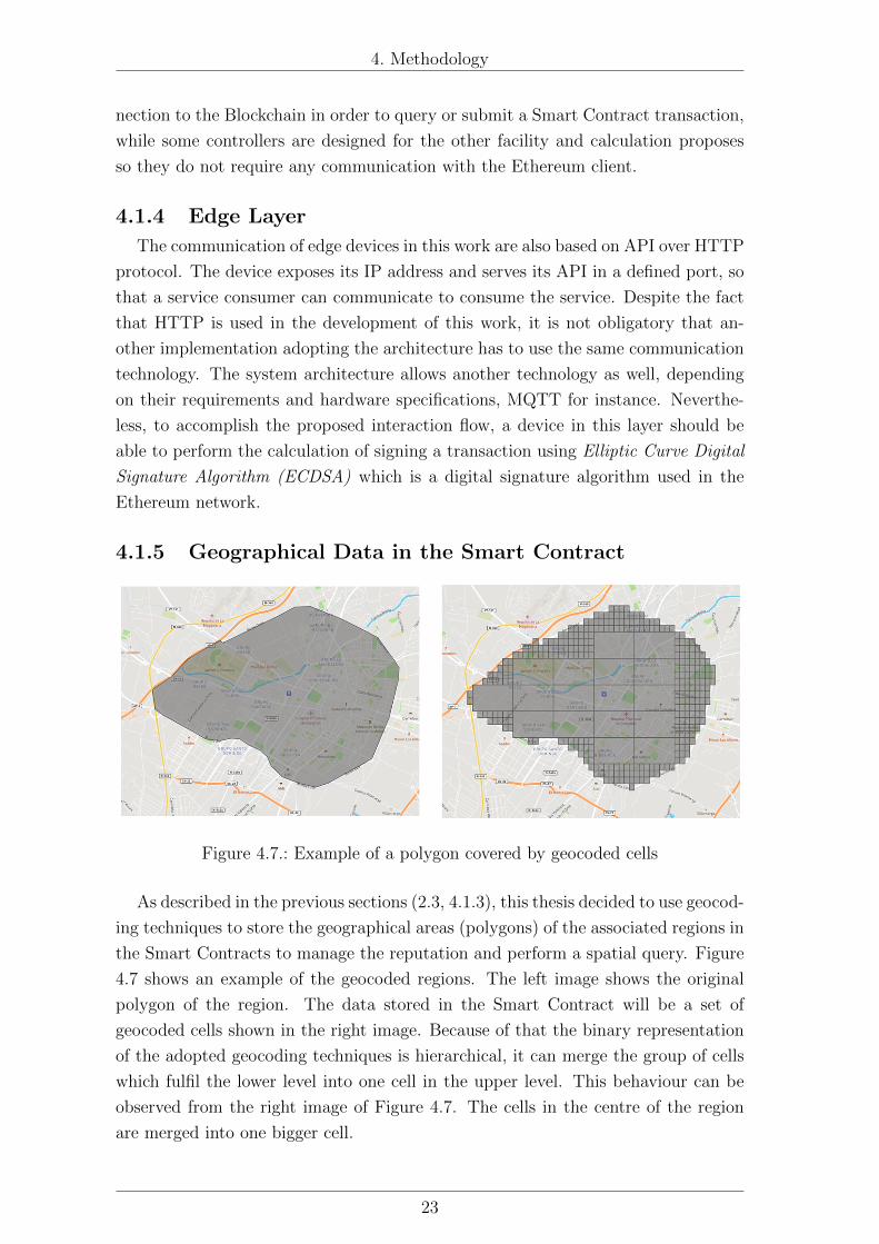
4.1.5 Geographical Data in the Smart Contract
Figure 4.7.: Example of a polygon covered by geocoded cells
As described in the previous sections (2.3, 4.1.3), this thesis decided to use geocod-
ing techniques to store the geographical areas (polygons) of the associated regions in
the Smart Contracts to manage the reputation and perform a spatial query. Figure
4.7 shows an example of the geocoded regions. The left image shows the original
polygon of the region. The data stored in the Smart Contract will be a set of
geocoded cells shown in the right image. Because of that the binary representation
of the adopted geocoding techniques is hierarchical, it can merge the group of cells
which fulfil the lower level into one cell in the upper level. This behaviour can be
observed from the right image of Figure 4.7. The cells in the centre of the region
are merged into one bigger cell.
23
Page 33
4. Methodology
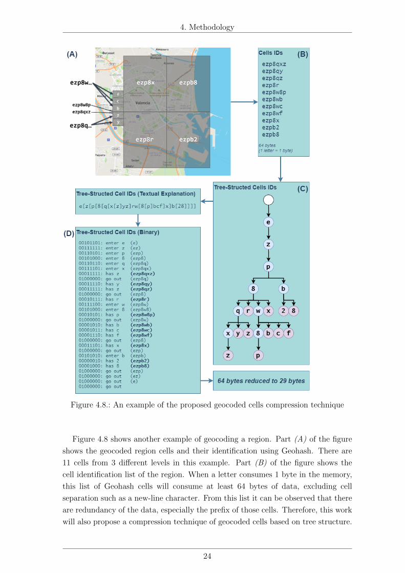
Figure 4.8.: An example of the proposed geocoded cells compression technique
Figure 4.8 shows another example of geocoding a region. Part (A) of the figure
shows the geocoded region cells and their identification using Geohash. There are
11 cells from 3 different levels in this example. Part (B) of the figure shows the
cell identification list of the region. When a letter consumes 1 byte in the memory,
this list of Geohash cells will consume at least 64 bytes of data, excluding cell
separation such as a new-line character. From this list it can be observed that there
are redundancy of the data, especially the prefix of those cells. Therefore, this work
will also propose a compression technique of geocoded cells based on tree structure.
24
Page 34
4. Methodology
Part (C) of Figure 4.8 shows the tree-based structure of this geocoded region. The
nodes in blue colour represent the cells that have children, while the nodes in purple
colour represent the final level that will be included in the region data. This tree
structure can be encoded into binary representation shown in part (D) of the figure.
Because a Geohash cell uses base32 representation, which requires only 5 bits to
store one level, storing it in one byte will have 3 bits remained unused. Therefore,
these 3 bits can store an additional information to indicate that the node cell has
children or not. The result from binary encoding this tree requires only 29 bytes to
store the data, which is less than a half of the original data that requires 64 bytes.
In the same way, an S2 cell list can also be compressed by the same algorithm.
However, an S2 cell uses 2 bits for one level, storing one level of 2-bit in one byte
is not sufficient. Therefore, the S2 cell will be grouped by 6 bits before being
structured to be a tree, the spare 2 bits are used for the level open or close marking
like Geohash. A 6-bit in this S2 cell can be represented by base64 representation.
The description of compressed data is explained in the appendix (Geocoded Data
Compression Structures).
4.2 Implementation and DevelopmentThe proposed architecture is an abstract structure and can be implemented using
any programming languages and tools. However, this section will explain the tools
used for developing the proof of the architecture in this thesis.
4.2.1 Fog Layer
The Ethereum network will be deployed using Go Ethereum (Geth)1, which
is an open-sourced implementation of the Ethereum Blockchain network using Go
language.
The fog API will be developed by JavaScript language run in NodeJS 2 en-
gine. The API serves requests on HTTP protocol using Express3 library, which is
available on NPM. The reason for using JavaScript as the programming language is
because of that it can communicate with Geth client using web3.js4 library. The
library also allows the interaction with a Smart Contract to be done in a simpler
way through Application Binary Interface (ABI) of the contract. Additionally, while
developing the Smart Contracts, it will use Truffle5 which is a programming suite
designed for Smart Contract development. Truffle contains multiple tools that al-
1https://geth.ethereum.org/2https://nodejs.org/3https://expressjs.com/4https://web3js.readthedocs.io/en/5https://www.trufflesuite.com/truffle
25
Page 35
4. Methodology
low to compile, test, and deploy the developed contracts written in Solidity into the
Ethereum network.
4.2.2 Edge Layer
The edge devices in this work are influenced by available hardware provided by
the university laboratory, which is Particle Development Board6. The device
has similar specification as Arduino, but the Particle board allows the possibility of
compiling and flashing the programme to the board using its cloud service. So that
the board does not have to be physically connected to the computer, but it needs
an internet connection instead. The programming for the device will be written
in C++ language. As described in the section 4.1.4, the communication between
edge devices will be done by API on HTTP protocol. Hence, the library that serves
this propose is ParticleRdWebServer 7 by robdobsn. Lastly, the board needs to
be able to sign the transactions using ECDSA so it will use micro-ecc8 library
provided by kmackay to do so.
4.3 Experiment DesignThis section describes the experiments designs and procedures, as well as their
evaluation. It is divided into three subsections, which are 4.3.1 Experiment:
Geocoding Techniques Comparison defines the procedures and criteria of com-
parison between the two geocoding techniques and the proposed compressing algo-
rithms (4.1.5), 4.3.2 Experiment: Contract Simulation which describes the
simulation of the proposed architecture to test the different aspects, lastly 4.3.3 Ex-
periment: Deployment and Scenario describes the implementation method-
ologies and the test case scenario.
4.3.1 Experiment: Geocoding Techniques Comparison
To answer the research question 3, this experiment is designed to compare between
Geohash and S2 geocoding techniques. Although the related works have already
indicated that S2 performs better in many aspects, there are still more aspects to
compare for the compatibility in the proposed algorithm.
The comparison will be performed by:
1. Covering or fitting a GeoJSON polygon into a list of geocoded cells (using
data of the administrative regions in Spain)
2. Compressing geocoded cells using the proposed algorithm
6https://www.particle.io/7https://github.com/robdobsn/ParticleRdWebServer/8https://github.com/kmackay/micro-ecc
26
Page 36
4. Methodology
In each step, it will compare the result by their output size and calculation time
4.3.2 Experiment: Contract Simulation
The second part of the experiments is to develop the Smart Contracts of the
proposed architecture and test their performance. This experiment is designed to
prove the architecture functionality, which will answer the research question 1. It is
also designed to test the manipulation of spatial data in the Smart Contracts, which
was mentioned in the research question 2. Lastly, it will be conducted twice in the
Smart Contracts based on both Geohash and S2 to compare and answer the research
question 3 as well. The procedure in this experiment is to measure the following:
1. Gas used to deploy the developed contracts into an Ethereum network
2. Input size and time spent for adding regions using Geohash and S2, either cell
array or the compressed tree
3. Time spent to query for a cell in the Smart Contract based on Geohash and
S2
4. Time spent to mine a block in an Ethereum blockchain using a personal com-
puter and a fog device (Raspberry Pi)
4.3.3 Experiment: Deployment and Scenario
The last experiment is to answer the research question 1 by proving that the
proposed architecture works in the IoT devices by deploying the programme into
both fog and edge devices. The fog devices used in this experiment are Raspberry
Pi, while the edge devices are Particle Development Board. The experiment will set
up the developed programme into the devices and use the described workflow to test
the communication between them. The expectation in this experiment is to confirm
that:
1. A fog node is able to serve as an Ethereum node
2. A service consumer is able to discover the available providers and their repu-
tation data, as well as provide a feedback after the consumption
3. A service provider is able to provide the service and able to sign the transaction
27
Page 37
5. Development and Experimental
Results
This chapter shows the development outcomes and the experiment results to proof
the proposed architecture. The first section (5.1) elaborates the outcomes of im-
plementing the architecture. The next three sections (5.2, 5.3 and 5.4) respectively
shows the results of the experiments designed in the previous section (4.3).
5.1 Development Outcomes
5.1.1 Smart Contracts
Figure 5.1.: Updated UML class diagram of the Smart Contracts for supporting bothgeocoding techniques
The Smart Contracts were successfully developed1. There are two different
geocoding techniques, which are Geohash and S2. Despite the different encoding
algorithms between these two techniques, both of them result in a binary integer
whose length indicates the hierarchical level of the cell. In other words, the binary
representation of the both techniques has the same structure. Therefore, they can
share the most of Smart Contract methods.
Figure 5.1 shows the diagram of developed contracts. The both geocoding tech-
niques inherit the same abstract contract called Regions, and they override the query
1GitHub repository: https://github.com/ponlawat-w/uji_mt-contracts
28
Page 38
5. Development and Experimental Results
method which is the only function that they have a different behaviour, because geo-
hash uses 5 bits to represent one level while S2 uses 2 bits. The Regions contract
was developed to be abstract, which means that its instance cannot be initiated.
After that, the Devices contract and the ReputationManagement contract were
developed.
Because of that this thesis only proposes an architecture and the related tech-
nologies, so the generating of reputation value is not focused nor defined. Therefore
a direct feedback from the fog device is used in ReputationManagement contract
just for proving that the contract can store and query for the value. The practical
implementation of the architecture will need to use these information of data quality
and the feedback to calculate the real reputation index.
5.1.2 Fog API
The API for communicating with the Smart Contracts was developed2. Each
fog node serves an API using the HTTP protocol, while it also communicates with
the Geth instance through internal channel at a different port. Therefore, the API
does not have to store the private key of the current node, but it can access the
Blockchain through Web3 API using a passphrase given by the key owner. Through
this, when a verified user wants to send a valid transaction through the fog node,
the user must attach the correct passphrase in its HTTP request header, the API
will use this passphrase to decrypt the private key and unlock the account.
When a user uses the API to call a Smart Contract method, the API needs to sub-
mit the contract call transaction to the Blockchain network, which is done by web3.js
library. However, in some cases, it might take a longer time for the Blockchain node
to mine a block and propagate the transaction. In consequence, waiting too long for
the transaction result might be interrupted by a request timeout response from the
HTTP connection. The user then receives an error even the transaction might be
correctly pushed to the Blockchain in next few minutes. To tackle this problem, in
the developed API, when a user calls a controller that submits a new transaction to
the Blockchain, after web3.js processes the request and submitted the transaction
for mining, it instantly returns the transaction hash of the contract call instead of
waiting until the transaction to be mined. A user then can use the hash with an-
other controller in the same API to check the transaction status, whether it is in a
queue, already mined, or rejected.
2GitHub repository: https://github.com/ponlawat-w/uji_mt-fog_api
29
Page 39
5. Development and Experimental Results
5.1.3 Edge Device
The service provider and consumer code in the edge device was developed3. The
ParticleRdWebServer library allows a service provider to serve simple requests from
its client. Nevertheless, the usage of micro-ecc library to sign a transaction some-
times work unexpectedly. Even it can sign a transaction using the private key and
can verify the signature by itself, but when the signature is submitted to the fog
node, it is recognised to be an invalid signature. The transaction submission request
then gets rejected by the fog node and returned as a fail result. This issue is solved
by defining the number of tries to the edge device. If the fog API cannot verify the
signature and responds with an error, the edge will sign and resubmit again and
again until it accepts a successful response from the fog API, or until it is out the
number of tries. From the observation, a transaction is usually successful between
first and third try, with sometimes up to the fifth try, so the suggested number of
attempts should be 5. However, the developed code configured the number to be 10
for preparing for an unexpected case.
Experiment Reproducibility
The programming code, the randomly-generated input data, and the preliminary
result in the experiments of this work were put into different GitHub repositories
described in the footnotes. According to Nust et al. (2018)’s work regarding the
reproducibility assessment of a research in GIScience, each assessment criterion can
be assigned by a number between 0 and 3 which respectively means unavailable,
documented, available, and available and open. The self assignment of this work
reproducibility level is by following:
• Input data: 2
• Methods preprocessing: 2
• Methods processing: 3
• Methods computational environment: 1
• Results: 1
3GitHub repository: https://github.com/ponlawat-w/uji_mt-edge_devices
30
Page 40
5. Development and Experimental Results
5.2 Experiment: Geocoding Techniques
ComparisonThis section shows and interprets the result of two different geocoding techniques
of Geohash and S2 4. However, there are some considerations regarding the bias
possibility in the results as there are differences in the selected input levels of both
techniques, as well as a different programming language used due to technical rea-
sons. This concern is elaborated in the following section (5.2.1), followed by the
experiment result (5.2.2).
5.2.1 General Concern and Bias Consideration
There are two issues needed to be concerned in this comparison experiment.
Firstly, the popular Geohash is based on base32 representation, despite the fact
that its binary notation allows level increasing by 2 bits as S2 does, but the common
Geohash libraries support only base32 manipulation. Hence, increasing one level in
a Geohash cell adds 5 more bits, but it adds 2 bits in case of S2. The consequence is
that there are no such levels where these two techniques provide a similar accuracy,
and yet they cannot be fairly compared.
Table 5.1 shows the comparison of a cell area size between Geohash and S2 in
different levels5. From the table it can be observed that at the same bit length,
Geohash has a smaller cell size which means it provides more precision than S2
at the same length. We can note that the number of S2 bits shown in the table
includes the end bit of 1 which is insignificant for interpreting the coordinates. For
this reason, before going to compare these two techniques it needs to decide the
factor for paring the levels, for example to be based on data length or cell size.
Since the Smart Contracts in this work store geocoded cells in a fixed-length integer
of 64 bits, the number of bits stored is not concerned regardless of its level; therefore
it compared between those levels whose area size are most similar, which are:
• Geohash level 4 and S2 level 9
• Geohash level 5 and S2 level 12
• Geohash level 6 and S2 level 14
• Geohash level 7 and S2 level 16
4GitHub repository of code in this experiment is available atGeohash: https://github.com/ponlawat-w/uji_mt-geohash_evaluation_test
S2: https://github.com/ponlawat-w/uji_mt-s2encoding5Geohash accuracy:https://stackoverflow.com/questions/13448595/
geohash-string-length-and-accuracy
S2 cell statistics: https://s2geometry.io/resources/s2cell_statistics
31
Page 41
5. Development and Experimental Results
Geohash Bit Cell Size S2 Bit Cell Size1 5 12,588,175.24 km2 0 4 85,011,012.19 km2
1 6 21,252,753.05 km2
2 8 6,026,521.16 km2
2 10 786,760.95 km2 3 10 1,646,455.50 km2
4 12 413,918.15 km2
3 15 12,293.14 km2 5 14 104,297.91 km2
6 16 26,113.30 km2
7 18 6,529.09 km2
4 20 768.32 km2 8 20 1,632.45 km2
9 22 408.12 km2
5 25 12.01 km2 10 24 102.03 km2
11 26 25.51 km2
12 28 6.38 km2
6 30 0.75 km2 13 30 1.59 km2
14 32 0.40 km2
7 35 11,723.65 m2 15 34 99,638.93 m2
16 36 24,909.73 m2
17 38 6,227.43 m2
8 40 732.73 m2 18 40 1,556.86 m2
19 42 389.21 m2
20 44 97.30 m2
9 45 11.45 m2 21 46 24.33 m2
22 48 6.08 m2
10 50 0.72 m2 23 50 1.52 m2
24 52 0.38 m2
11 55 111.81 cm2 25 54 950.23 cm2
26 56 237.56 cm2
27 58 59.39 cm2
12 60 6.99 cm2 28 60 14.85 cm2
29 62 3.71 cm2
13 65 0.11 cm2 30 64 0.93 cm2
Table 5.1.: Maximum error (cell size) of different levels in Geohash and S2 GeocodingTechniques
Secondly, another consideration is the possible bias regarding the calculation time.
As the proposed architecture is based on JavaScript for the aforementioned reason,
the library used for encoding the areas will also be developed in JavaScript. However,
there is no any S2 region covering libraries available in JavaScript library database
as of found. The official S2 library is available in C++, Go language and Python.
Go language is selected for this comparison. This leads to the consideration that Go
language is a compiled language, while JavaScript is an interpreted language; this
programming language selection might affect the comparison quality.
32
Page 42
5. Development and Experimental Results
5.2.2 Comparison Results
File size
Figure 5.2.: Graph showing the file size (in kilobytes) comparison between Geohashand S2 technqiues
Figure 5.2 shows the size in kilobytes of resulted geocoded cells, using the adminis-
trative region polygons in Spain as the input data. The stable horizontal lines, black
solid and dashed, are sizes of original polygons in Well-Known Binary (WKB) and
GeoJSON respectively. The row CompressedGeohash and S2 shows the file sizes of
the cell ID lists in each technique. The row GeohashTree and s2base64tree shows
the file sizes of compressed cell ID lists using the proposed algorithm. The Graph
is shown in the logarithm scale. The result shows a very similar file size between
Geohash and S2 for preserving a similar precision. It also shows that the proposed
compressing algorithm can significantly reduce the size from the prefix-redundant
list. It also demonstrates that using compressed Geohash level 6 or S2 level 14
can save disk space than the original polygonal data, but for the next level, both
techniques consume a larger space than the WKB data.
Number of Resulted Cells
Figure 5.3 shows the number of cells outputted from Geohash and S2 geocoding
techniques. The graph is displayed using a logarithm scale. From the graph, it can
be observed that Geohash and S2 resulted in a similar number of cells, but they are
uncertain for defining which one is better, as S2 contains more number of cells in the
lower level, while in the higher-level Geohash requires more. The reason could be
caused by the characteristics of the input data, such as the alignment of the input
polygons.
33
Page 43
5. Development and Experimental Results
Figure 5.3.: Graph showing the number of cells resulted from fitting areas togeocoded cells using Geohash and S2 techniques
Figure 5.4.: Graph showing calculation time for geocoding and compressing the datausing Geohash and S2 techniques
Calculation Time
Figure 5.4 shows time spent for calculation in geocoding the polygons using Geo-
hash and S2 techniques. The results between two techniques are too different. The
y-axis has to be split, with the left (blue) axis indicates Geohash calculation time in
second, and the right (orange) indicates S2 calculation time in the same unit. From
the result, it can be observed that S2 is much faster than Geohash as converting the
whole areas spent less than even 10 seconds in the highest precision, while Geohash
took more than ten minutes to accomplish all the tasks. However, the reason be-
34
Page 44
5. Development and Experimental Results
hind this difference could be, as described in the previous section (5.2.1), that they
used a different programming language. Furthermore, the library used for fitting
the polygons into S2 cells is the official library developed by the S2 developer team,
but the Geohash library is developed by a third-party developer.
35
Page 45
5. Development and Experimental Results
5.3 Experiment: Contract Simulation
Figure 5.5.: The region divisions of data used in the simulation experiment
This section shows the simulation results of deploying the smart contracts into
the Ethereum network. There are four experiments in this section, which are 1)
gas consumption in the contract deployment, 2) interacting performance with the
contracts, and 3) mining performance of the devices in the system.
Figure 5.5 shows the region divisions of data used in this experiment. The lo-
cations used in querying and device mobility assessment in this experiment are
randomly generated within these regions.
Gas Consumption in the Contract Deployment
This experiment measures the Ethereum gas spent on deploying the developed
Smart Contracts into the Ethereum Network. Figure 5.6 shows the result of the
experiment. From the result, it can be observed that Regions and Devices Contracts
use more gas comparing to the other contracts. This is caused from the number of
methods and the computational operations in the contracts. It can also be observed
that the implementation of the regions based on S2 geocoding technique consumes
slightly more gas than the Geohash one. The reason behind this difference could be
that the operations in S2 have to handle the end bit of the cell when changing the
level, while the action is unnecessary in Geohash.
36
Page 46
5. Development and Experimental Results
Figure 5.6.: Gas consumption in contracts deployment
Interacting Performance with the Regions Contracts
This experiment added a number of example regions data (Figure 5.5) into the
Smart Contracts that use Geohash and S2. The design of this experiment divided
data inputs into three different levels. In case of Geohash, the maximum cell lengths
are 6, 7, and 8. And in case of S2, they are 14, 17, and 19. However, the Smart
Contracts returned an out of gas error when trying to add the regions of the third
level in the both techniques (Geohash: 8, S2: 19). For this reason, this experiment
results will only show the first two lengths:
• Geohash Precision 1 : 6
• Geohash Precision 2 : 7
• S2 Precision 1 : 14
• S2 Precision 2 : 17
Figure 5.7 shows the input data lengths of the different regions contracts im-
plementation. The precision #2 of Geohash tree returned an error of out of gas,
therefore it cannot be included to the result graph. From the result it can be ob-
served that the sizes of tree-based compressed input data are significantly less than
37
Page 47
5. Development and Experimental Results
Figure 5.7.: Graph showing the sizes of the input data used for adding new regionsinto the contracts
Figure 5.8.: Graph showing gas consumption when adding new regions into the con-tracts
the cell lists.
Figure 5.8 shows gas consumption when adding the regions into the Smart Con-
tract. Despite their significant smaller size of input data, adding data using the trees
consumes more gas than using only an array of geocoded cells. A possible reason is
that using Ethereum to expand the tree causes an additional cost of computation.
Figure 5.9 shows time spent to add the regions data into the Smart Contract.
38
Page 48
5. Development and Experimental Results
Figure 5.9.: Graph showing time spent when adding new regions into the contracts
It can be observed that in some cases tree-base input data spends more time than
cells array but it results in another way in the other cases. There might be another
factor that affects the calculation time in this experiment, however, by the current
result data it is difficult to conclude which one is faster.
The last experiment is the query experiment. This experiment randomly gener-
ated 6,000 points in the space and used the same data set to test the query time in
the Smart Contracts based on Geohash and S2. In these 6,000 points, 5,000 of them
are belong to an existing region in the Smart Contracts, the other 1,000 are the
points that do not fall into any region. Figure 5.10 shows a boxplot of the experi-
ment results. From the results, it can be observed that in the similar level, querying
for a cell in Geohash is slightly faster than S2. The reason can be that one level of
a Geohash cell requires 5 bits of data while S2 requires 2 bits. For this reason, to
query for a cell over the data, Geohash requires 7 iterations to check across all the
levels and S2 requires up to 32 iterations to check.
Mining Performance of the Devices in the System
This experiment was designed to compare the possibility and performance of
the Ethereum nodes using IoT devices when mining a new block to the chain. It
compares a personal computer of 4-core CPU and a Raspberry Pi which is used
as a fog device. However, due to hardware limitation, the Raspberry Pi did not
manage to mine any block. Instead, it returned an out of memory error and halted
the Ethereum client. For this reason, despite the fact that Raspberry Pi can be a
node in Ethereum network and can submit the transactions, it cannot be a miner to
39
Page 49
5. Development and Experimental Results
Figure 5.10.: Graph showing time spent when querying for a cell in the contracts (inmillisecond)
publish the chain. A possible solution to this issue is to modify the implementation
of the Ethereum network to use a different consensus algorithm, whose default is
Proof-of-Work, to be the Proof-of-Authority algorithm6. However, this experiment
continued to measure the mining time using only the personal computer running
on the different thread numbers, keeping the default consensus algorithm which is
Proof-of-Work. Figure 5.11 shows the results of the experiment. As expected, using
more thread tends to spend less time to mine a block into the chain. The mining
time indicates time needed to publish a transaction into the network. Hence, from
the results it can take up to minutes for a change in the Smart Contract to be
propagated over the network.
6https://ethereum.stackexchange.com/questions/24955/
geth-mining-on-32bits-host-raspberry-pi-memory-error
40
Page 50
5. Development and Experimental Results
Figure 5.11.: Graph showing time spent when mining a new block into the chain (insecond)
5.4 Experiment: Deployment and ScenarioThis sections describes the results and related discussions after having deployed
the proposed architecture into the real IoT devices.
Fog Layer
The APIs and a Geth client were installed into a Raspberry Pi 4. After using the
API to interact with the Smart Contracts, it showed that the Raspberry Pi 4 has
enough potential to serve as an API and run an Ethereum node at the same time.
The Raspberry Pi, whose operating system is based on Linux, is also able to run
another service, including SSH, which allows a remote access to the device. Hence,
it is not necessary to be physically with the node in order to maintain, update or
41
Page 51
5. Development and Experimental Results
Figure 5.12.: The instalment of test scenario: edge service provider, edge serviceconsumer, fog Raspberry Pi
configure it. The shell script7 enables Raspberry Pi to run the API and Geth client
as a service, therefore it is simpler for the administrator to access the device via
SSH and execute the service command in order to start, stop the service, as well
as diagnose it when there is a problem. The Smart Contracts allowed the devices
to register themselves with their IP address information. Once it is added into the
Blockchain, another node can also see the list of the registered fog nodes and their
IP addresses, so that they can use the IP address as a URL base for the API.
However, in this test scenario, the registered IP addresses is in the same LAN
network. In practice, fog node can be installed in a different area which uses a
different internet network. It might be necessary to consider using another service
to forward device IP address or using a VPN to let the device be accessible from
outside.
Figure 5.12 shows the instalment of this test experiment. The Raspberry Pi who
acts as a fog node is located as a black box in the right side of the image.
Edge Layer
In the test scenario, the edge service provider was attached to a temperature and
humidity sensor, and exposed the services into its device registration data. However,
due to lack of equipment, it was unfortunately not able to equip a GPS module or
7GitHub repository: https://github.com/ponlawat-w/uji_mt-raspi_scripts
42
Page 52
5. Development and Experimental Results
Figure 5.13.: The service consumer status LED shows in green (trust) and orange(not trust)
any positioning module to it. Thus, the device’s position had to be simulated and
manually set by the user, which is not supposed to be the case in the practical
implementation.
After the device had been switched on, it was able to received an Ethereum
address and private key from the user, and register itself to the Smart Contracts
through the fog API. To send the transaction, the device managed to sign a trans-
action and submit to the fog API. Using an HTTP caller application in the personal
computer (in this case Postman), it was able to communicate with the edge device
through its API served on the exposed IP address. The IP address of the device can
be discovered by query in the contract via the fog API. It was also able to query for
the reputation value using fog API and establish a new connection to consume the
service. The service provider returned correct values of the service, and parallelly
sent the observed data to the fog node as defined in the architecture. Finally, after
finishing the service consumption, the user sent a feedback to the fog node, which
was later calculated (or random in this work) to be a new updated reputation value
of the service, and updated in the Smart Contracts. When a user query again for
43
Page 53
5. Development and Experimental Results
the reputation value, the smart contract returns the updated value as expected.
The experiment was extended by changing the service consumption from being
manual to automatic by using another edge device. The service consumer device
is equipped with an LED that can emit light in red-green-blue shades of colour.
The device was programmed to expose its communication status via LED, which is
red when it cannot connect to the fog node, orange when there is no any satisfying
reputed service provider in the area, blue when it is establishing a new connection
with a service provider, and green when it is correctly consuming the service. The
result shows that the service consumer worked correctly. It emitted an orange signal
when the queried area has no service providers whose reputation value satisfied the
threshold, and it emitted a green one when there was a service provider that was
trusted and selected to establish a new connection as shown in Figure 5.13.
44
Page 54
Conclusion and Future Work
ConclusionThis thesis has proposed an architecture of reputation and device management
system in IoT, based on the cloud-fog-edge architecture. The architecture in this
work uses device location to determine its associated area, which is a factor in manag-
ing the reputation data. The management system is implemented in the fog layer in
a decentralised way by using Blockchain technologies. The work adopted Ethereum
as a Blockchain network because it provides a Smart Contract which allows an ex-
ecutable programme to be stored in the Blockchain network. The Smart Contracts
store the spatial data of associated areas for discovering and querying registered
services and their reputation values. For complexity and performance reasons, a
polygon object that represents an area is encoded using hierarchical geocoding tech-
niques: either Geohash or S2. This work also proposed a compression algorithm
aimed to reduce the geocoded data.
The first experiment of this work compared Geohash and S2 geocoding techniques
(RQ3). Despite a few concerns regarding the comparison, the experiment results
showed that S2 took a significant less time to encode a polygon into a list of cells.
In term of data size, there were no much difference between the two techniques. The
proposed compression algorithm showed a satisfied outcome, because it can largely
reduce the data size.
The second experiment implemented the proposed architecture and test it with a
large number of random input data (RQ1, 2). The experiment also run twice on the
different Smart Contracts based on Geohash and S2 (RQ3). The results showed that
the Smart Contracts were able to function as expected to manage the reputation
values and device service discovery in a decentralised way. The Smart Contract
based on Geohash was able to query for a region faster and consumed less Ethereum
gas than the S2 one because there are less iterations in changing the cell level.
However, the compressed data using the proposed compression algorithm consumed
more gas in the Smart Contracts, which means the compression algorithm is not
suitable for the current proposed architecture. The experiment also resulted that
Raspberry Pi was unable to mine a block in the Ethereum network using the default
Proof-of-Work as a consensus algorithm due to its hardware limitation, which means
without changing the Blockchain consensus algorithm, it needs a bigger computer
as another node in the fog layer in order to keep the Blockchain network to be
functional.
The last experiment deployed the developed architecture to the IoT devices by
45
Page 55
Conclusion and Future Work
using Particle boards as the edge devices and Raspberry Pi as the fog device (RQ1).
The result demonstrated that the Raspberry Pi as a fog node was able to serve an
API service and interact with the Smart Contracts. In the edge layer, the service
provider was able to serve its service, and able to sign the transaction to interact with
the Smart Contract through the fog layer. At the same time, the service consumer
was also able to communicate with the fog layer in order to discover a provider with
its reputation data, and was able to make a decision to consume the service based
on the reputation data.
Encountered Problems and SolutionsThis section discusses the problems encountered during this thesis and their so-
lutions.
Bitwise Operations in JavaScript : The implementation of proposed archi-
tecture in this work is based on JavaScript language for the reasons elaborated in
4.2, 4.3.3. An unexpected problem during the implementation regarding the limi-
tation of JavaScript was that, this language does not support bit-wise operation for
an integer with length more than 32 bits (Mozilla Developer Network, 2020). The
reason is that although the language stores the numeric data in 64 bits, the binaries
are in IEEE 754 floating-point standard, not in a general integer. The default inte-
ger that is supported by the language is only 32-bit length. The problem occurred
when working with the geocoded data, especially in S2, whose data are stored with
a 64-bit integer. This issue can be tackled by using an external library or splitting
every data into two parts, 32-bit each. However, there were no intensive bit-wise
operations in the proposed algorithms; hence, for simplicity reason, the data were
converted to hexadecimal numbers as a textual string, and handled by built-in string
functions.
Gas Limit in Ethereum : An execution of Smart Contracts in an EVM is
based on gas value, similar to electric consumption in a physical computer. The
method caller has to pay for the gas at the rate of gas price defined in each network.
The amount of gas spent in a method is defined by Ethereum, which is varied and
depends on the opcodes executed in the Smart Contract. Consequently, sending a
big input data to the Smart Contract consumes more gas and is likely to be failed
due to the gas limit. The solution to this problem is to chunk the input data into a
smaller size, and send them in separated transactions.
Positioning Module in Edge Device : The designed architecture uses the
spatial context to query and manage devices and their reputation data. Therefore,
an edge device is expected to be movable and, consequently, equipped with a po-
sitioning module, for example, a GPS module. However, due to the environment
46
Page 56
Conclusion and Future Work
limitation of the university laboratory, the time constraint of the thesis, and the
avoidance of physical working due to the ongoing pandemic in the time of this work,
it was not able to obtain a positioning module for the edge devices to test the sce-
nario of the architecture. Thus, the service consumption API in the provider device
exposed another endpoint to let the user to manually set its location. In a practical
implementation, this API endpoint is expected to be removed, and replaced by a
data reading function from the positioning module. The location read is expected to
be geocoded into Geohash or S2 cell, depended on the technique used in the Smart
Contracts.
Result Discussion
Architecture
The results in 5.1, 5.3 and 5.1 showed that the proposed architecture was func-
tional, either in a simulation mode within a single machine, or in an IoT system
using distributed devices. A fog device can be an Ethereum node to handle the
Smart Contract execution. There were some delay for a transaction to be mined as
a new block over the network, which is an expected disadvantage of the Blockchain.
Hence, using the Blockchain network might not be suitable for a real time system,
or a system that updates data frequently.
In addition, not only a fog device, but an edge also showed that it can be a part of
the Blockchain network despite its limited computational ability, because it was able
to perform the ECDSA calculation to sign a transaction using an assigned private
key. This ability in the edge device allows the proposed architecture to be more
secure, because even the fog node who submits the transaction for edge devices,
they cannot tamper its data as long as the private key is not known.
Spatial Smart Contract
The experiment results showed that a spatial context can be added to the Smart
Contract. The contract in the system was not designed for storing an exact original
polygon, instead, the data were geocoded before added to the Smart Contract. A
trade-off of using geocoding techniques is the loss of precision, because the geocoded
data are not able to exactly represent the original area. This drawback affects the
accuracy when querying a point near the border of an area. However, the main
objective of this work is not to store the same geographical object in the Smart
Contracts, but to use it as a spatial context of managing and querying for data;
hence, this error is acceptable. Furthermore, the geocoded data can also be sorted
and indexed in a data lookup table, so it can easily and quickly find out whether a
cell is inside any region or not, without involving any geometric calculation.
47
Page 57
Conclusion and Future Work
Geocoding Techniques
This work used two geocoding techniques: Geohash and S2. The result from the
section 5.2 showed no significant difference between the two techniques in terms of
size. However, the experiment in 5.3 showed that Geohash was slightly faster in the
developed Smart Contracts. Therefore, it is enough to use Geohash in the proposed
architecture unless there are further developments that need the advantages of the
S2.
Suggestions for Future DevelopmentThis section suggests the possibilities of the further development in several as-
pects. Firstly, this work proposed only a management architecture, but not the
calculation of the value. The information collected from the devices in this work
can be used in the future works to generate a real reputation value of the service
providers, such as using a machine learning technique to detect abnormalities in the
sensory data, or to use the feedback from the consumers as a factor to calculate the
value.
There is vulnerable information transmitted between devices in the proposed
architecture, which is the Ethereum private key when assigning a new device or
the passphrase when communicating with the fog API. To avoid the data being
eavesdropped by a third person, in practice, it is suggested to use a secure HTTP
channel (HTTPS) to encrypt the messages in the communication.
Additionally, this work proposed an abstract architecture for managing the rep-
utation values that can be applied in the other IoT applications. In practical im-
plementation, the communication between devices in a system can follow a common
IoT standard, such as Mozilla WebThings8 or OGC SensorThings9. The integration
between the architecture and these standards is needed to be studied in the future
to make the proposed concept to be more practical.
Regarding the geocoding techniques, the experiments demonstrated that Geo-
hash is enough for the current work. However, the related works shows that S2
performs better in the different aspects. Therefore, the usage of S2 and its fur-
ther spatial computation can be more studied for the future works. Furthermore,
the geocoded data in this work were also compressed by the proposed tree-based
algorithm, which was later empirically proved that it does not help to reduce the
Ethereum gas consumption. Nevertheless, its advantage of significant data size re-
duction could be taken in another future work. In the other way, the data structures
inside the Smart Contracts of this work could be changed to take the compression
8https://iot.mozilla.org/9https://www.ogc.org/standards/sensorthings
48
Page 58
Conclusion and Future Work
advantage from the algorithm.
Finally, this thesis demonstrated the possibility of manipulating spatial data in
a decentralised application. Despite the Smart Contract limitations compared to
a traditional application, it is worth further studying more advanced spatial data
manipulation in a decentralised context. To be more precise, this work only use the
geocoding technique for querying the spatial data. The future development could
extend this part and perform a different spatial calculation, for example a range
query, region adjacency, intersection, or handling other spatial data types such as
points or lines.
49
Page 59
Bibliography
Artz, D. and Gil, Y. (2007). A survey of trust in computer science and the semantic
web. Journal of Web Semantics, 5(2):58 – 71. Software Engineering and the
Semantic Web.
Ashton, K. (2009). That ’Internet of Things’ Thing. RFID Journal.
Atzori, L., Iera, A., and Morabito, G. (2011). Siot: Giving a social structure to the
internet of things. IEEE Communications Letters, 15(11):1193–1195.
Atzori, L., Iera, A., Morabito, G., and Nitti, M. (2012). The social internet of things
(siot) – when social networks meet the internet of things: Concept, architecture
and network characterization. Computer Networks, 56(16):3594 – 3608.
Balkic, Z., Sostaric, D., and Horvat, G. (2012). Geohash and uuid identifier for multi-
agent systems. In Jezic, G., Kusek, M., Nguyen, N.-T., Howlett, R. J., and Jain,
L. C., editors, Agent and Multi-Agent Systems. Technologies and Applications,
pages 290–298, Berlin, Heidelberg. Springer Berlin Heidelberg.
Buterin, V. et al. (2014). A next-generation smart contract and decentralized ap-
plication platform. white paper, 3(37).
Chen, J., Tian, Z., Cui, X., Yin, L., and Wang, X. (2019). Trust architecture and
reputation evaluation for internet of things. Journal of Ambient Intelligence and
Humanized Computing, 10(8):3099–3107.
Cisco (2015). Unleash the power of the internet of things. Cisco Systems Inc.
Debe, M., Salah, K., Rehman, M. H. U., and Svetinovic, D. (2019). Iot public fog
nodes reputation system: A decentralized solution using ethereum blockchain.
IEEE Access, 7:178082–178093.
Deiotte, R. and Valley, R. L. (2017). Comparison of spatiotemporal mapping tech-
niques for enormous etl and exploitation patterns. ISPRS Annals of Photogram-
metry, Remote Sensing & Spatial Information Sciences, 4.
Ethereum (2020). Types —Solidity 0.7.5 documentation. https://docs.
soliditylang.org/en/v0.7.5/types.html. [Online. Accessed on 28 January
2021].
Fernando, E., Meyliana, and Surjandy (2019). Blockchain technology implemen-
tation in raspberry pi for private network. In 2019 International Conference on
Sustainable Information Engineering and Technology (SIET), pages 154–158.
50
Page 60
Bibliography
Golosova, J. and Romanovs, A. (2018). The advantages and disadvantages of the
blockchain technology. In 2018 IEEE 6th Workshop on Advances in Information,
Electronic and Electrical Engineering (AIEEE), pages 1–6.
Gubbi, J., Buyya, R., Marusic, S., and Palaniswami, M. (2013). Internet of things
(iot): A vision, architectural elements, and future directions. Future Generation
Computer Systems, 29(7):1645 – 1660. Including Special sections: Cyber-enabled
Distributed Computing for Ubiquitous Cloud and Network Services & Cloud Com-
puting and Scientific Applications — Big Data, Scalable Analytics, and Beyond.
Guo, J., Chen, I.-R., Wang, D.-C., Tsai, J. J. P., and Al-Hamadi, H. (2019). Trust-
based iot cloud participatory sensing of air quality. Wireless Personal Communi-
cations, 105(4):1461–1474.
Guttman, A. (1984). R-trees: A dynamic index structure for spatial searching.
In Proceedings of the 1984 ACM SIGMOD International Conference on Manage-
ment of Data, SIGMOD ’84, page 47–57, New York, NY, USA. Association for
Computing Machinery.
Huh, S., Cho, S., and Kim, S. (2017). Managing iot devices using blockchain plat-
form. In 2017 19th International Conference on Advanced Communication Tech-
nology (ICACT), pages 464–467.
Kouicem, D. E., Bouabdallah, A., and Lakhlef, H. (2018). An efficient architecture
for trust management in ioe based systems of systems. In 2018 13th Annual
Conference on System of Systems Engineering (SoSE), pages 138–143.
Lamport, L., Shostak, R., and Pease, M. (1982). The byzantine generals problem.
ACM Transactions on Programming Languages and Systems, 4(3):382–401.
Lenzini, G., Bargh, M. S., and Hulsebosch, B. (2008). Trust-enhanced security
in location-based adaptive authentication. Electronic Notes in Theoretical Com-
puter Science, 197(2):105–119. Proceedings of the 3rd International Workshop on
Security and Trust Management (STM 2007).
Lu, H. and Ooi, B. C. (1993). Spatial indexing: Past and future. IEEE Data Eng.
Bull., 16(3):16–21.
Mingxiao, D., Xiaofeng, M., Zhe, Z., Xiangwei, W., and Qijun, C. (2017). A review
on consensus algorithm of blockchain. In 2017 IEEE International Conference on
Systems, Man, and Cybernetics (SMC), pages 2567–2572.
Moussalli, R., Srivatsa, M., and Asaad, S. (2015). Fast and flexible conversion of geo-
hash codes to and from latitude/longitude coordinates. In 2015 IEEE 23rd Annual
51
Page 61
Bibliography
International Symposium on Field-Programmable Custom Computing Machines,
pages 179–186.
Mozilla Developer Network (2020). Expressions and operators - JavaScript
— MDN. https://developer.mozilla.org/en-US/docs/Web/JavaScript/
Reference/Operators. [Online. Accessed on 30 January 2021].
Mui, L., Mohtashemi, M., and Halberstadt, A. (2002). A computational model of
trust and reputation. In Proceedings of the 35th Annual Hawaii International
Conference on System Sciences, pages 2431–2439.
Nakamoto, S. (2008). Bitcoin: A peer-to-peer electronic cash system. Satoshi
Nakamoto Institute.
Nust, D., Granell, C., Hofer, B., Konkol, M., Ostermann, F. O., Sileryte, R., and
Cerutti, V. (2018). Reproducible research and giscience: an evaluation using agile
conference papers. PeerJ, 6:e5072.
Suwardi, I. S., Dharma, D., Satya, D. P., and Lestari, D. P. (2015). Geohash index
based spatial data model for corporate. In 2015 International Conference on
Electrical Engineering and Informatics (ICEEI), pages 478–483.
Trilles, S., Lujan, A., Belmonte, O., Montoliu, R., Torres-Sospedra, J., and Huerta,
J. (2015). Senviro: A sensorized platform proposal using open hardware and open
standards. Sensors, 15(3):5555–5582.
Victor, F. and Zickau, S. (2018). Geofences on the blockchain: Enabling decen-
tralized location-based services. In 2018 IEEE International Conference on Data
Mining Workshops (ICDMW), pages 97–104.
52
Page 62
Appendix
Base32 and Base64 RepresentationBase32 and base64 are binary encoding techniques which convert a binary data
in to a textual representation. A character in base32 represents 5 bits of data. For
this reason, there are 25, which is 32, different characters to represent the binary
group. In a similar way, a character in base64 represents 6 bits of data, so there are
64 different characters to represent a data group in base64.
Table A.1 and A.2 shows the representation in base32 and base64, respectively.
Decimal Binary Base32 Decimal Binary Base320 00000 0 16 10000 h
1 00001 1 17 10001 j
2 00010 2 18 10010 k
3 00011 3 19 10011 m
4 00100 4 20 10100 n
5 00101 5 21 10101 p
6 00110 6 22 10110 q
7 00111 7 23 10111 r
8 01000 8 24 11000 s
9 01001 9 25 11001 t
10 01010 b 26 11010 u
11 01011 c 27 11011 v
12 01100 d 28 11100 w
13 01101 e 29 11101 x
14 01110 f 30 11110 y
15 01111 g 31 11111 z
Table A.1.: Base32 representation used in Geohash
53
Page 63
Appendix
Dec Base64 Dec Base64 Dec Base64 Dec Base640 A 16 Q 32 g 48 w
1 B 17 R 33 h 49 x
2 C 18 S 34 i 50 y
3 D 19 T 35 j 51 z
4 E 20 U 36 k 52 0
5 F 21 V 37 l 53 1
6 G 22 W 38 m 54 2
7 H 23 X 39 n 55 3
8 I 24 Y 40 o 56 4
9 J 25 Z 41 p 57 5
10 K 26 a 42 q 58 6
11 L 27 b 43 r 59 7
12 M 28 c 44 s 60 8
13 N 29 d 45 t 61 9
14 O 30 e 46 u 62 +
15 P 31 f 47 v 63 /
Table A.2.: Base64 representation
Geocoded Data Compression StructuresGeohash uses 5 bit to store one level. The first bit is not used. The next two
bits indicate the open or close marking: 00 to be the end of the tree, 01 to be open
mask, 10 to be close mask. The last five bits store the base32-encoded data, which
will be 00000 when it is a close byte.
For example,
• 0 00 01011 means in the current level there is the cell c
• 0 01 10111 means in the current level there are children in the cell r
• 0 10 00000 means it is a close byte
In the other hand, S2 data need to be encoded using base64 (or group by 6 bits).
The first two bits indicate the open or close with the same notation as Geohash.
The last six bits store the data.
For example,
• 00 100110 means in the current level there is base64 of m which is 38
• 01 010111 means in the current level there are children in base64 of X
• 10 000000 means it is a close byte
54