80
Decoding Ogg Vorbis Audio with The C6416 DSP, using a custom made MDCT core on FPGA by Henric Kärnhall LiTH-ISY-EX--07/4039--SE Linköping 2007

Decoding Ogg Vorbis Audio with The C6416 DSP,
using a custom made MDCT core on FPGA
by
Henric Kärnhall
LiTH-ISY-EX--07/4039--SE
Linköping 2007


Decoding Ogg Vorbis Audio with The C6416 DSP,
using a custom made MDCT core on FPGA
Master thesis in Electronic Systems
At Linköping Institute of Technology
by
Henric Kärnhall
LiTH-ISY-EX--07/4039--SE
Linköping 2007-06-08
Supervisor: Jonas Carlsson
Examiner: Kent Palmkvist


URL för elektronisk version http://www.ep.liu.se
Publikationens titel Decoding Ogg Vorbis Audio with The C6416 DSP, using a custom made MDCT core on FPGA
Författare Henric Kärnhall
Sammanfattning
Abstract Ogg Vorbis is a fairly new and growing audio format, often used for online distribution of music and
internet radio stations for streaming audio. It is considered to be better than MP3 in both quality and
compression and in the same league as for example AAC. In contrast with many other formats, like
MP3 and AAC, Ogg Vorbis is patent and royalty free.
The purpose of this thesis project was to investigate how the C6416 DSP processor and a Stratix II
FPGA could be connected to each other and work together as co-processors and using an Ogg Vorbis
decoder as implementation example.
A fixed-point decoder called Tremor (developed by Xiph.Org the creator of the Vorbis I specification),
has been ported to the DSP processor and an Ogg Vorbis player has been developed. Tremor was
profiled before performing the software / hardware partitioning to decide what parts of the source code
of Tremor that should be implemented in the FPGA to off-load and accelerate the DSP.
Nyckelord Ogg, Vorbis, Tremor, FPGA, DSP, C6416, MDCT, Porting, Profiling, Hardware
Presentationsdatum
2007-06-08
Publiceringsdatum
(elektronisk version)
Institution och avdelning Institutionen för systemteknik
Department of Electrical Engineering
Språk
Svenska
X Annat (ange nedan)
Engelska
Antal sidor
63
Typ av publikation
Licentiatavhandling
X Examensarbete
C-uppsats
D-uppsats
Rapport
Annat (ange nedan)
ISBN (licentiatavhandling)
ISRN LiTH-ISY-EX--07/4039--SE
Serietitel (licentiatavhandling)
Serienummer/ISSN
(licentiatavhandling)


iii
Abstract
Ogg Vorbis is a fairly new and growing audio format, often used for
online distribution of music and internet radio stations for streaming
audio. It is considered to be better than MP3 in both quality and
compression and in the same league as for example AAC. In contrast
with many other formats, like MP3 and AAC, Ogg Vorbis is patent and
royalty free.
The purpose of this thesis project was to investigate how the C6416
DSP processor and a Stratix II FPGA could be connected to each other
and work together as co-processors and using an Ogg Vorbis decoder as
implementation example.
A fixed-point decoder called Tremor (developed by Xiph.Org the
creator of the Vorbis I specification), has been ported to the DSP
processor and an Ogg Vorbis player has been developed. Tremor was
profiled before performing the software / hardware partitioning to decide
what parts of the source code of Tremor that should be implemented in
the FPGA to off-load and accelerate the DSP.


v
Acknowledgements
I would like to thank my family and friends who have supported me
during the time I have been working on this project. I would also like to
send tributes to the Xiph.Org foundation and all members of the Vorbis
mailing lists.


vii
Contents
1 Introduction .....................................................................................1
1.1 Background...............................................................................1
1.2 Purpose .....................................................................................1
1.3 Objectives.................................................................................2
1.4 Limitations................................................................................2
1.5 Project plan...............................................................................2
1.6 Previous work ...........................................................................4
1.7 Document overview..................................................................5
1.8 Reading instructions .................................................................5
1.9 Notations ..................................................................................5
1.10 Glossary....................................................................................6
2 Digital Audio coding ........................................................................7
2.1 General audio coding ................................................................7
2.1.1 Lossless coding ............................................................7
2.1.2 Lossy coding ................................................................7
2.1.3 Psychoacoustic audio coding........................................8
2.1.4 Masking .......................................................................9
2.1.5 MDCT and window functions ....................................10
2.2 Ogg Vorbis .............................................................................11
2.2.1 Encoding ....................................................................11
2.2.2 Decoding....................................................................12
2.2.3 Tremor .......................................................................13
2.2.4 License.......................................................................13
3 The Hardware................................................................................15
3.1 Digital Signal Processors in general........................................15
3.2 The TMS320C6416 DSP ........................................................16
3.2.1 Enhanced DMA controller..........................................17
3.2.2 External Memory Interface.........................................18
3.2.3 DSP/BIOS..................................................................18
3.3 Field Programmable Gate Array in general.............................18
3.4 The Stratix II EP2S60 FPGA ..................................................19

viii
3.5 Co-Processing.........................................................................19
3.6 Development boards ...............................................................20
3.7 Summary ................................................................................20
4 Porting and Profiling Tremor .......................................................21
4.1 Overview ................................................................................21
4.2 Memory allocation..................................................................23
4.3 Callbacks for file I/O ..............................................................23
4.4 Possible optimizations ............................................................24
4.5 Debugging and Verification....................................................25
4.5.1 Code Composer Studio...............................................25
4.5.2 Parallel single-stepping ..............................................25
4.5.3 Verification ................................................................26
4.6 Profiling Tremor .....................................................................26
4.7 Summary ................................................................................28
5 The Ogg player...............................................................................29
5.1 Overview ................................................................................29
5.2 Limitations..............................................................................30
5.3 SDRAM..................................................................................30
5.4 AIC23 Stereo Codec ...............................................................31
5.5 Implementation.......................................................................31
5.5.1 Buffer handling ..........................................................33
6 Connecting FPGA and implementation .......................................35
6.1 Overview ................................................................................35
6.2 Atlantic interface ....................................................................36
6.2.1 Slave Source to Master Sink.......................................37
6.2.2 Master Source to Slave Sink.......................................38
6.3 Software / Hardware Partitioning............................................39
6.4 Butterfly calculation ...............................................................42
6.5 The Implementation................................................................43
6.6 Adapting Tremor ....................................................................44
6.7 Results ....................................................................................45
7 Further improvements...................................................................47
7.1 Synchronous EMIF.................................................................47
7.2 Further hardware implementation ...........................................47
7.3 Resource allocation and assignment........................................48
7.4 Improving the player...............................................................48
7.5 The ultimate implementation ..................................................48

ix
8 Results and Conclusion..................................................................51
8.1 Acceleration and CPU usage...................................................51
8.1.1 Communication overhead...........................................51
8.1.2 CPU Usage.................................................................52
8.1.3 Task activity in the player ..........................................53
8.2 Verification and final result ....................................................53
8.3 Conclusion..............................................................................53
Glossary.............................................................................................55
Tremor License.................................................................................59
Bibliography......................................................................................61

xi
List of figures
Figure 1-1: Simple overview of the system..............................................1
Figure 1-2: Project plan ...........................................................................3
Figure 2-1: Ideal lossy- and lossless encoder ...........................................8
Figure 2-2: Absolute threshold of the human auditory system .................9
Figure 2-3: Example of spectral masking...............................................10
Figure 3-1: Typical environment for a DSP processor ...........................15
Figure 4-1: Workflow of porting Tremor ...............................................22
Figure 4-2: Cycle distribution in ov_read (audio packet decoding) ........27
Figure 4-3: Cycle distribution in Inverse MDCT....................................28
Figure 5-1: Overview of the system .......................................................29
Figure 5-2: Overview of the AIC23 codec .............................................31
Figure 5-3: Program flow of the Ogg player ..........................................32
Figure 5-4: Example with three buffers..................................................33
Figure 6-1: Block-diagram of connection between DSP and FPGA.......35
Figure 6-2: Slave Source to Master Sink................................................37
Figure 6-3: Sending a package from a Slave Source to a Master Sink....37
Figure 6-4: Master Source to Slave Sink................................................38
Figure 6-5: Sending a package from a Master Source to a Slave Sink....39
Figure 6-6: New design of mdct_backward............................................41
Figure 6-7: Structure of butterfly operations ..........................................42
Figure 6-8: Block-diagram of the MDCT core design............................43
Figure 6-9: Waveform illustrating the concept of data transfer ..............44
Figure 8-1: Communication overhead....................................................51
Figure 8-2: Task activity in the player....................................................53


1
Chapter 1
1Introduction
1.1 Background
The most known and used audio compression technique of today is by far
MP3. But despite its popularity it suffers from a number of drawbacks
and several codecs have been developed to replace MP3. However, most
of them, like MP3, have restrictive licenses and royalty fees.
Ogg Vorbis is a fairly new and growing audio format that is considered
to be better than MP3 in both quality and compression. But in contrast
with many other formats, Ogg Vorbis has been developed as an open
source project and is patent and royalty free.
1.2 Purpose
Figure 1-1: Simple overview of the system
The purpose of this thesis project is to establish a connection between the
C6416 DSP and a Stratix II FPGA and investigate the possibilities on
how they can communicate and be used as co-processors. This should be
done using an Ogg Vorbis decoder as an implementation example. This
thesis is therefore focusing on two subjects: Co-processing design and the
Ogg Vorbis compression technique. Figure 1-1 illustrates a simple
overview of the system that will be implemented.
C6416 DSP For decoding
and playing
Ogg files
Stratix II FPGA A Co-processor
for intensive
calculations
DAC Headphone or
Loudspeaker
SDRAM
File storage

2
1.3 Objectives
The objectives are:
• Port an existing Ogg Vorbis decoder (Tremor) to the DSP. • Develop and implement an Ogg Vorbis player for the DSP that can decode and play Ogg files in real time.
• Establish a connection between the DSP and the FPGA. • Use the FPGA as a Co-Processor to the DSP to perform heavy calculation and hopefully gain some acceleration.
• Investigate how the DSP and the FPGA works together using the Ogg Vorbis decoding as an example.
• Give suggestions on how one could continue and improve the work that is done in this thesis project.
1.4 Limitations
Since this thesis includes three very different problems (port Tremor,
develop a player and design accelerating hardware) that individually
might take very long time to complete and that also have to function
together – time will be a very limited resource. The focus has therefore
been to complete the three problems and suggest a solution that is
functional but might not give a very good result in terms of acceleration
of cycles. And then give suggestions on how one could continue to
improve the work.
Furthermore, the communication between hardware will be built on an
already existing reference design. If there is a limitation in this design
(like a bottleneck) it will also be a limitation for the final solution,
because no time will be spent on redesigning it.
1.5 Project plan
First to be developed was a project plan, it is illustrated in Figure 1-2. In
the preface a lot of reading and research was done. The Ogg Vorbis
format and previous works on similar problems was studied. After
porting Tremor to the DSP the work was divided in two different paths,
one was to develop a Ogg player for the DSP and the other was to profile
Tremor and with an iterative process move calculation intensive part of
the software into hardware. And finally put everything together. All along
the work results have been produced that will be presented through this
thesis.

3
Figure 1-2: Project plan
Prestudy on Ogg
Vorbis and Previous
work
Start
Porting Tremor library
to the C6416 DSP
Develop an Ogg Vorbis
player for the C6416 DSP
Profiling Tremor Results
Prestudy on the
hardware
Design and test
DSP�FPGA connection
Yes
SW/HW Partitioning
Design hardware
Testing and Profiling
Have time to do more
work?
Results
No
Results
Integrate hardware
acceleration to the Ogg
player if possible
Final test
Stop

4
1.6 Previous work
Since Ogg Vorbis is an open source project it encourage among others
students and interested people to use it in there own projects and share
there experience. Mailing lists exists and it is fairly easy to get in touch
with other developers. Some master thesis have been written on the
subject and three of them with similar purpose as this project have been
studied. They are all aiming to port Tremor to a specific hardware,
usually with limited resources and then perform optimizations to make it
run in realtime.
Ogg Vorbis Decoder For Motorola DSP56002 [1]
Niklas Barsk, 2005
Investigates the possibilities to decode an Ogg Vorbis stream with the
Motorola DSP56002, clocked at 40 Mhz. Memory limitations limited the
Ogg strem to about 1 second and the decoding was far from possible to
do in real time.
Ogg/Vorbis in embedded systems [2]
Erik Montnémery and Johannes Sandvall, 2004
Investigates if it is possible to run an Ogg/Vorbis decoder in a strictly
memory constrained embedded environment. The target hardware is the
TMS320C5510 DSP clocked at 200 Mhz. Code optimizations and
replacing MDCT with a DSP assembler optimized FFT.
Design of an Audio Player as System-on-a-Chip [3]
Luis Azuara and Pattara Kiatisevi, 2002
An Ogg Vorbis audio decoder was implemented as system on a chip. The
open source LEON SoC platform was used. The entire MDCT core was
replaced by hardware and the FPGA was clocked in only 25 Mhz.
The thesis made by Luis Azuara and Pattara Kiatisevi is the most
advanced and it is known in the Ogg Vorbis community. It is also the
most similar to this thesis since they are using software / hardware co-
design techniques. The main difference is that the complete system is
located on a single chip, the MDCT core together with a soft processor is
implemented in an FPGA. The system on a chip project is available as
open source but it could unfortunately not be reused since it is build on an
older version of Tremor.
There are also a number of Ogg Vorbis decoding chip available from
which consumer products can be built. But they are not open and little
information is available.

5
1.7 Document overview
Chapter 2 - Gives an introduction to audio coding in general and
introduces Ogg Vorbis and the Xiph.Org foundation. It also
briefly describes the encoding and decoding of Vorbis files.
Chapter 3 - Gives some general information about DSP processors and
FPGAs. And further introduces the specific hardware that
have been used in this thesis.
Chapter 4 - Describes how Tremor was ported to compile and run on the
C6416 DSP. It also discusses the result from the profiling of
Tremor.
Chapter 5 - Describe the concept of how the Ogg player works and some
details on how it was implemented.
Chapter 6 - Describes how the DSP was connected with the FPGA, the
software / hardware partitioning and finally how the
hardware was implemented.
Chapter 7 - Enumerates some suggestions on how one could continue to improve this project.
Chapter 8 - Discusses the results of the project and conclude the thesis.
1.8 Reading instructions
Besides reading the entire thesis from back to back, readers could be
satisfied with chapter 2, 4 and 5 if only interested in Ogg Vorbis and the
decoding procedure. On the other hand, if not interested in Ogg Vorbis
but instead the hardware aspects and the implementation the reader can
focus on chapter 3, 6 and 7.
1.9 Notations
Function names are written in italics, for example main().And signal
names are written in bold, for example enable. Source code examples are
always written between two lines as in List 1-1
Code example..
List 1-1: Code example

6
1.10 Glossary
This thesis contains a lot of abbreviations. From now on most of them are
explained at the first encounter, if not considered to be general
knowledge. But all of them are listed in Appendix A with a short
explanation.

7
Chapter 2
2Digital Audio coding
This chapter gives a short introduction to audio coding in general. The
Ogg Vorbis audio format is briefly discussed and finally compared with
other formats. For readers interested in audio coding, and especially
perceptual audio coding, [6] is recommended reading.
2.1 General audio coding
Audio coding means compressing audio, data which is a form of data
compression designed to reduce the size of audio files.
The compression techniques can be divided in two categories: lossy-
and lossless coding.
2.1.1 Lossless coding
Lossless coding is a technique which means that the original data can be
perfectly reconstructed from the compressed data without any artifacts.
This is in some cases an advantage but the main drawback is that it is
much harder to get a good compression. Examples of lossless codecs are
Dolby TrueHD1, FLAC
2 and SHN
3.
2.1.2 Lossy coding
Most codecs, including Ogg Vorbis, uses some kind of lossy
compression and from now on only lossy coding will be discussed. With
lossy coding it is possible to achieve a much higher compression rate than
1 Dolby TrueHD - http://www.dolby.com/consumer/technology/trueHD.html 2 FLAC - http://flac.sourceforge.net/ 3 SHN (shorten) - http://www.softsound.com/Shorten.html

8
lossless compression. Most lossy codecs combine the two methods to
achieve high compression rate and at the same time maintaining
acceptable audio quality.
The lossy coding is done by reducing perceptual redundancy by first
identifying sounds which are considered perceptually irrelevant, that is,
sounds that are very hard to hear. Typical this include high frequencies or
sounds that occur at the same time as other louder sounds (this is called
masking and will be discussed later). Those redundant sounds are coded
with lower accuracy or not coded at all. To do this type of coding a
psychoacoustic model of the human ear is needed.
Because data are removed during lossy compression it is not possible to
perfectly reconstruct it and should therefore not be used when a audio file
will be encoded more than one time.
Figure 2-1 illustrates the ideal lossy- and lossles encoder.
Figure 2-1: Ideal lossy- and lossless encoder
2.1.3 Psychoacoustic audio coding
As mentioned before psychoacoustic audio coding is a set of lossy
compression that intend to remove sound that is inaudible for the human
ear, based on a model of the human auditory system. The human ear can
nominally hear sounds in the range 20 Hz to 20 kHz and are most
sensitive to sounds around 3 kHz. See Figure 2-2.
The Absolute Threshold of Hearing (ATH) is the sound pressure level
that is needed for a pure tone to be audible in a noiseless environment. It
can be approximated by equation (2.1) and it is plotted in Figure 2-2.
Redundancy
Perceptual redundancy
Audible sound
Perceptual redundancy
Audible sound
Audible sound Ideal lossy
encoder
Ideal
lossless
encoder
Original audio data Compressed audio data Encoding

9
Figure 2-2: Absolute threshold of the human auditory system
( )4
33.3
10006.0
8.0
1000105.6
100064.3
2
+−
= −
−−
−f
ef
fT
f
q (2.1)
All tones appearing below the absolute threshold will not be heard by the
human ear. The inaudible parts of the spectrum are generally removed in
the frequency domain after a transformation from the time domain.
2.1.4 Masking
Masking is the phenomena when a sound is made inaudible in presence of
another stronger sound. The phenomena is both frequency and time
dependent, therefore two categories of masking excises: spectral and
temporal. Figure 2-3 illustrates the concept of spectral masking with an
example where a 1 kHz tone is masking the surrounding frequencies.
The weaker tone at a slightly higher frequency will not be heard because
it now appears below the masking threshold.
102 10
3 10
4
Frequency
Sound
pressure
level,
SPL
20
40
60
80
100
0
dB
Hz

10
Figure 2-3: Example of spectral masking
Temporal masking appears in a similar manner but instead of masking
the surrounding frequencies it causes pre- and post-masking in the time
domain. The post-masking lasts about ten times longer than the pre-
masking.
2.1.5 MDCT and window functions
To perform the quantization based on the result from the psychoacoustic
analysis, the audio must be transformed to the frequency domain. This
could be done by a Discrete Cosine Transform (DCT) or a Discrete
Fourier transform (DFT), but due to block artifacts these transformations
are not a convenient solution. This kind of block artifact can for example
be seen in a JPEG image that is very hard compressed.
Instead most audio coders uses the Modified Discrete Cosine
Transform (MDCT) combined with overlapping windowing. Compared
to DCT, MDCT does not keep the DC component which is not needed in
audio.
Frequency
102 10
3 10
4
20
40
60
80
100
0
This tone will be
inaudible
1kHz tone masking
surrounding sounds
Sound
pressure
level,
SPL
dB
Hz

11
MP3 and some other coders uses the sine window, equation (2.2). But
Ogg Vorbis and recent formats like AAC and AC3 uses a Kaiser-Bessel
derived window, equation (2.3). The advantages of the Kaiser-Bessel
window is better stopband attenuation at the expense of lesser passband
selectivity.
Sine window: ( )
+= 5.02
sin kN
wk
π (2.2)
Vorbis window: ( )
+= 5.02
sin2
sin 2 kN
wk
ππ (2.3)
2.2 Ogg Vorbis
Christopher Montgomery founded the Xiph.Org [4] foundation which is
now a collection of open source multimedia related projects. The most
well known are Vorbis (audio) and Theora (video). Ogg is a container
format capable of including both Vorbis and Theora but is mostly known
as an audio format. From now on when mentioning “Ogg” it will refer to
the Ogg Vorbis audio format.
The first stable codec version 1.0, was released on the 19th of July 2002
and complies to the Vorbis I Standard [9]. The purpose was to develop a
general purpose high quality audio codec that was completely open, non-
proprietary and patent and royalty free. The project started shortly after it
was decided to strengthen the control of MP3 and to sue free MP3
projects.
Many on-line radio stations are today streaming Ogg Vorbis, not only
because it is royalty free but because it has been accepted to be in the
same league as for example AAC and similar and with better
performance than MP3 and WMA.
2.2.1 Encoding
The Ogg Vorbis standard only specifies how the decoding is to be done,
leaving more flexibility to the encoder. The intention is to avoid
restrictions on the encoder that might prevent it from using newer
methods that would increase the performance. Xiph.org does however
provide a reference encoder as an example.
12
2.2.2 Decoding
The following description of the decoding procedure will be very brief
and much information will be omitted. For a deeper description of the
different packets (down to bit level precision) and all the decoding steps it
is highly recommended to take a look at the Vorbis I Specification [9].
The Vorbis stream can be divided into four parts:
Identification header - Identifies the stream as Vorbis and specify
version, sample rate and number of channels etc.
Comment header - Contains album, artist, title and user comments etc.
Setup header - Specifies codec setup information such as huffman
codebooks etc.
Audio packet - Contains the audio data. The audio packet are decoded
as the following process describes:
After the three mandatory setup packets (header) have been received the
decoding of the audio packets may begin. The decoding procedure can be
divided in the following 12 steps:
1 Decode packet type flag
2 Decode mode number
3 Decode window shape
4 Decode floor
5 Decode residue into residue vectors
6 Inverse channel coupling of residue vectors
7 Generate floor curve from decoded floor data
8 Compute dot product of floor and residue, producing audio
spectrum vector
9 Compute Inverse MDCT
10 Overlap/Add left-hand output of transform with right-hand output
of previous frame
11 Store right hand-data from transform of current frame for future
lapping
12 If not first frame, return results of overlap/add as audio result of
current frame
After overlapping and adding the preceding window the result has been
decoded to Pulse Code Modulation (PCM) samples, ready to be used as

13
output, for example sent to a digital to analog converter or written to a
file.
Since every frame has to be lapped and the first frame only contain
valid data in the right part, the output from the first decoder pass is zeroed
out.
2.2.3 Tremor
Tremor is an integer-only, fully Ogg Vorbis compatible decoder, written
by Xiph.org. Tremor is the decoder that will be used in this thesis project.
There are a number of different other versions available that will be
discussed in Section 4.1.
2.2.4 License
The Ogg Vorbis specification [9] is in the public domain and available
for anyone to use, both commercial and non-commercial. Tremor are
available under a BSD-like license (see Appendix B) and most of
Xiph.org’s utility software are released under the terms of GNU GPL.
BSD is compared to GPL more business friendly since it allows
commercial closed source project to derive from the source code. But if a
source code has a GPL license then all derived source codes must remain
open and also have a GPL license.

15
Chapter 3
3The Hardware
This chapter describes the general use of Digital Signal Processors (DSP)
and Field Programmable Gate Arrays (FPGA) and further the specific
hardware that has been used in this thesis project. The concept of Co-
processing will also be discussed.
3.1 Digital Signal Processors in general
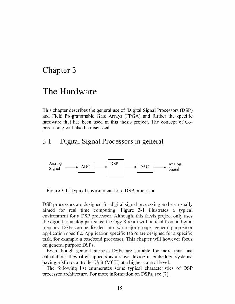
Figure 3-1: Typical environment for a DSP processor
DSP processors are designed for digital signal processing and are usually
aimed for real time computing. Figure 3-1 illustrates a typical
environment for a DSP processor. Although, this thesis project only uses
the digital to analog part since the Ogg Stream will be read from a digital
memory. DSPs can be divided into two major groups: general purpose or
application specific. Application specific DSPs are designed for a specific
task, for example a baseband processor. This chapter will however focus
on general purpose DSPs.
Even though general purpose DSPs are suitable for more than just
calculations they often appears as a slave device in embedded systems,
having a Microcontroller Unit (MCU) at a higher control level.
The following list enumerates some typical characteristics of DSP
processor architecture. For more information on DSPs, see [7].
DSP ADC DAC
Analog
Signal Analog
Signal

16
• Harvard architecture (separate data and program memory) • Special instructions for Multiply And Accumulate (MAC), useful for vector products and Finite Impulse Response (FIR) filter
structures
• Hardware loops with no overhead for loop counters and branching
• Handles data overflow with guards and saturation • Internal data types have higher precision than native • Special address generation units, for example modulo and bit-reversed addressing
3.2 The TMS320C6416 DSP
TMS320 is a blanket name for a series of digital signal processors from
Texas Instruments. In this thesis project the C6416 DSP has been used, it
is a member of the C6000 family that are designed for extremely high
performance. Others are for examples the C5000 family with good power
efficiency and the C2000 family that is control optimized with control
peripheral integration and is also suitable for low cost applications.
The C6416 DSP is a fix point processor that is operating at a clock
frequency of up to 1 Gz. The C6416 DSP has a Very Long Instruction
Word (VLIW) architecture that basically mean that the compiler at
compile time searches for parallelism in the code and then pack
instructions that can be executed in parallel into one long instruction
word. VLIW architectures achieves high processing rates at the cost of
compile time. The C6416 DSP can issue up to eight 32 bit instructions in
a single clock cycle.
Cache memories and DSP processors are not always associated, but this
general purpose DSP has a L1/L2 Cash memory architecture where the
first level is divided into 16Kb Direct Mapped Program Cache and 16Kb
2-Way Set-Associative Data Cache. The second level is a 1024Kb
Unified Mapped RAM/Cache.
The processor core has 64 general purpose registers with 32bit width,
and eight independent functional units, six Arithmetic Logic Units (ALU)
and two multipliers. The VLIW architecture makes it possible to reach a
peak at 8000 MIPS when clocked in 1 Ghz. For more detailed
information on the C6416 DSP, see the data sheet [13].
An important feature with DSPs are the ability access memories and
other peripheral devices with high speed. The solution to this on the

17
C6416 DSP will be described in the following two sections 3.2.1 and
3.2.2. A short description of DSP/BIOS used by the C6416 is also
discussed in section 3.2.3.
3.2.1 Enhanced DMA controller
The Enhanced DMA (EDMA) is a Direct memory access (DMA)
controller that allows data transfers without interfering the CPU equipped
with a number of additional features. The EDMA includes several
enhancements to the common DMA such that it provides 64 channels
with programmable priority, and it has the ability to link data transfers.
The C6416 DSP can transfer data between on-chip and off-chip locations
using either the Central Processing Unit (CPU) or the EDMA. Typically,
blocks of data and transfer requests from peripheral devices are
performed by the EDMA. It can also perform data transfer between two
external memory spaces.
A typical configuration of an EDMA channel could look like the one in
List 3-1. Although, a few more lines of code are needed to get it
initialized and running.
EDMA_Config myConfig = {
0x41200000, // options
0x80000000, // source address
0x00000040, // transfer count
0x80010000, // destination address
0x00000004, // index
0x00000000 // element count reload and link address
};
EDMA_config(hEdma,&myConfig);
List 3-1: Example of EDMA configuration
The option field includes information such as priority, element size,
source and destination dimension (1D or 2D) and updating mode for
address pointers, interrupt information, linking parameters and frame
synchronization. For a complete description of the EDAM, see [14].
In this project the EDMA controller has been used to transfer blocks of
data between the DSP and the FPGA.
18
3.2.2 External Memory Interface
The External Memory Interface (EMIF) provides a glueless interface to a
variety of external memory components including SDRAM, SRAM,
ROM, and First In First Out (FIFO) buffers. A glueless interface means
that no additional control or logic circuits are needed. The C6416 DSP
has two EMIF: EMIFA- 64bit, EMIFB-16bit. In this project the EMIFA
is used together with the EDMA when interfacing and communicating
with the FPGA.
3.2.3 DSP/BIOS
DSP/BIOS is a name for a real-time operating system, developed by
Texas Instrument for there DSPs. It includes Run Time Analysis Tools,
Configuration Tools and Application Programming Interface (API)
libraries.
It has features such as preemptive multi-threading, communication
between tasks and memory management. The DSP/BIOS is consisting of
many smaller modules that is compiled and linked into the application if
needed rather than a full operating system that exists separately from the
code. It acts more like a code library that perform operating system type
functions.
The Configuration Tool abstracts the hardware and allows the user to
create and configure DSP/BIOS objects, such as EDMA controllers, data
loggers, timers, tasks etc. It is also used to configure memory, heaps,
thread priorities, and interrupt handlers.
The Run Time Analysis Tools allows the user to view program and
thread activity in real-time.
The configuration tool and run-time analysis tools are integrated in
Code Composer Studio (CCS), the Integrated Development Enviroment
(IDE) that was used when working with the C6416 DSP.
3.3 Field Programmable Gate Array in general
A FPGA is a programmable logic semiconductor device. It contain
programmable logic components and a hierarchy of programmable
interconnects allowing the logic blocks to be interconnected as needed.
The logic blocks can be programmed as simple logical gates or more
complex combinatorial functions such as multiplexers or math functions.
Most modern FPGAs also includes different kind of memory elements
and DSP blocks with fast multipliers and MAC structures.
The ability to freely design custom logical function makes it possible to
create parallel computing architectures with very high throughput. The

19
ability to re-program the devices makes them suitable for general
prototyping and specially for Application Specific Integrated Circuit
(ASIC) prototyping.
The high throughput of FPGAs makes them suitable for DSP
applications, video, networking, cryptography, computer hardware
emulation etc. FPGAs are also often seen as co-processors to a DSP or a
MCU, that will be discussed in section 3.5.
3.4 The Stratix II EP2S60 FPGA
The FPGA used in this thesis project is Stratix II EP2S60 from Altera.
The Stratix II FPGA family is based on a 1.2 V, 90 nm SRAM process
and is designed for high performance.
The EP2S60 FPGA has 60 k equivalent Logic Elements (LE), 2.5 Mbit
internal RAM and 36 DSP blocks with a total of 144 18x18 multipliers,
718 I/O pins and can be clocked at up to 550 Mhz. However, the
maximum clocking frequency is highly dependent on what and how the
implementation is made. In this thesis project a 100Mhz clock was used
and the synthesis tool needed to do some optimization to fulfill the timing
requirements.
To really get a meaning of these numbers (e.g. 60 k LE) one need to
study the structure of the logical elements and make comparisons with
other manufacturers1. For more detailed information, see the data sheet
[18]. The most interesting for this thesis is that the FPGA is designed for
high performance and that it has fast hardware multipliers. Neither the
number of logical elements nor the internal memory will be a problem.
3.5 Co-Processing
A co-processor is a special purpose processor used to supplement the
functions of the primary processor. Operations performed by the co-
processor may for example be floating point arithmetic, audio, graphics,
signal processing or encryption. A FPGA can for example acts as a co-
processor to a DSP and a DSP can act as a co-processor to a MCU. The
purpose of the co-processor is usually to offload the main processor or to
perform calculations that simply is not possible to accomplish by the
main processor.
A number of co-processors are used in ordinary PC computer, for
example the graphic processor on the graphic card is as a co-processor to
the CPU. Others may be used for audio and networking. Another subject
field that is very popular is embedded systems which usually consists of a
1 E.g. Xilinx, Lattice, Actel or Atmel

20
number of processors working together. In this thesis project the Stratix II
FPGA will be used as a co-processor to the C6416 DSP.
3.6 Development boards
Two development boards have been used: the Stratix II EP2S60 DSP
Development Board (for the FPGA) and the TMS320C6416 DSP Starter
Kit (for the DSP). Both boards are equipped with similar expansion
connectors making it possible to stack them on each other. The expansion
connectors are on the DSP side connected to the EMIF buss.
Although the FPGA board has support for a lot of devises such as:
Audio I/O, VGA output, Ethernet, Compact Flash, onboard memories,
push-button switches and a lot of various analog and digital I/O, the only
devices that have been used are the FPGA, some user LEDs and two 7-
segment displays for debugging- and status information.
The DSP board has been more utilized with the onboard SDRAM, the
AIC23 codec and its audio output connector and some user LEDs. The
DSP board also have some various digital I/O. For more information on
the development boards, see [19] and [15].
3.7 Summary
As the reader might have noticed, the hardware that will be used in this
thesis project is aimed for high performance applications. The DSP is
actually one of the fastest general purpose DSP on the market today
(2006). And the combination of the DSP and the FPGA can perform
extremely calculation intensive tasks (compared to audio decoding).
This hardware configuration is certainly not needed to decode an Ogg
audio stream in real-time. The DSP can itself perform the decoding
without any problem.
But even though the DSP might execute the decoding only using a
small part of its capacity, one can still use the Ogg audio decoder as an
example to investigate how to connect and communicate between the
DSP and FPGA in a co-processor environment. And the acceleration can
be measured by counting cycles.

21
Chapter 4
4Porting and Profiling Tremor
This chapter describes how Tremor was ported to compile and run on the
C6416 DSP. Solutions for hardware configurations with limited resources
will also be discussed. Furthermore the verification of the porting will be
described. After Tremor was ported the source code was profiled to get
basic data for the software / hardware partitioning.
4.1 Overview
This project is based on Tremor, which is an fixed-point implementation
of an Ogg Vorbis decoder. Tremor is written in C and designed for easy
porting and integration in larger projects. It does not need any libraries
other than the standard C library and the file stream I/O can be replaced
with whatever functions the programmer like, by using a callback
interface.
There are two1 main versions of Tremor available, a general purpose
implementation primarily aimed at Advanced RISC Machine (ARM) [21]
based processors, and a low-mem version aimed at DSP decoding.
The low-mem version uses less memory than the standard version, but
with the drawback of more calculation. Tremor perform all calculations
using 32-bit Fixed point arithmetics, and finally round the result down to
16 bit PCM samples.
The ARM architecture is a 32-bit RISC processor architecture. It is
very popular in embedded designs due to their power saving features and
therefore dominant in the mobile electronics market, where low power
1 There are also a special no-byte version available for non byte-addressable architectures,
this means that the smallest addressable unit is not a 8bit. For example the C55xx DSPs has
16bit as smallest unit and DSP56002 has 24bit as smallest unit. But the C6416 is byte addressable.

22
consumption is a critical design goal. However, we are not interested in
the general purpose implementation, nor the ARM processor, since we
will use a DSP processor.
To port Tremor to the C6416 DSP the work flow shown in Figure 4-1
was in advance decided and then applied. Compiling and running Tremor
on a PC was done without any changes of the source code, everything
worked at the first attempt, as predicted. A small test program that decode
a file and print out the PCM data was included in the source code of
Tremor from Xiph.org. This program was slightly rewritten to produce a
proper output that could easily be examined and compared with other
outputs. An equivalent test program was also written for the C6416 DSP.
Besides smaller changes like typecasts, defines and some missing
include files, two problems occurred during the porting, they will be
described in the following sections: 4.2 and 4.3. The debugging and
verification procedure is then described in a section 4.5.
Figure 4-1: Workflow of porting Tremor
Equivalent
Done
Yes
No
Porting Tremor to
compile on the
C6416 DSP
Compile Tremor
on a PC
Write a test
program
Write a test
program
Compare results.
Correct?
Debugging:
Use parallel-
single stepping
with PC
version to see
where it fails.
Prestudy, any
known issues or
problems porting
Tremor?

23
4.2 Memory allocation
The memory allocation in Tremor is handled using the standard C library
functions malloc(), calloc(), free() and alloca(). The alloca() function
dynamically allocates space in the stack frame of the caller. This
temporary space is automatically freed on return. The use of alloca()
caused some problems since the compiler for the C6416 processor did
not implement alloca(). The solution to this was to use an implementation
by D A Gwyn [8], which is available in the public domain.
The concept of this implementation is to keep track of all alloca-
allocated blocks, and reclaim any that are found to be deeper in the stack
than the current invocation. This heuristic does not reclaim storage as
soon as it becomes invalid, but it will do so eventually. As a special case,
alloca(0) reclaims storage without allocating any. alloca(0) can be used
to force garbage collection.
The implementation by Gwyn of alloca() might slow down the memory
allocation compared to a standard C library implementation. And the use
of malloc(), calloc() and free() should be replaced with the DSP/BIOS
functions MEM_alloc(), MEM_calloc() and MEM_free() which are
written for the C6416 DSP. These functions are probably faster and have
the advantage that one can specify what memory segment that should be
used for each allocation. However, these functions were not used, mostly
because MEM_free() need to know how much memory it should release,
and that information was not always available without adding more code.
4.3 Callbacks for file I/O
Tremor provide two different functions to open Ogg files, ov_open() and
ov_open_callbacks(). ov_open() uses the standard C I/O functions to open
and read a file, such as fopen(), fread() and fclose(). ov_open_callbacks()
provide the possibility to specify custom I/O functions. Since the file is
located in memory ov_open_callbacks() was a suitable solution. The
custom function read(), seek(), close() and tell() had to be written but
since the file is located in memory and with the decision that the data
should not be seekable and treated strictly as a stream the implementation
became trivial. If a seekable stream is wanted, seek() and tell() have to be
rewritten.

24
4.4 Possible optimizations
There are some optimizations that can be done to the source code of
Tremor to reduce the memory consumption and the computing load on
the CPU. Non of these optimizations have been made in this thesis
project since the hardware resources is not a limit. This section can
therefore be skipped if the reader is not interested in source code
modifications of Tremor.
The required changes to reduce memory consumption or computing
load will in some cases cause either reduced sound quality or make the
decoder not to fulfil the Ogg Vorbis specification. Despite the fact that
the specification might not be fulfilled these optimizations might be
necessary if one is developing a system with limited resources. There are
also features in the specification that are outdated or that no known
encoder are using and can therefore safely be removed.
Here follows some suggestions on source code optimizations that can
be done:
Remove floor 0: Floor 0 is not to be considered deprecated, but it is of
limited modern use. No known Vorbis encoder past Xiph.Org's own beta
4 makes use of floor 0. Floor 1 is also considerably less expensive to
decode than floor 0 [9]. Removing support for floor 0 will preserve
memory.
Window sizes: Remove all look-up tables for IMDCT support of
window lengths other than 256 and 2048. This is possible since these are
the only windows lengths that is used by most (if not all) encoders. Since
the current Vorbis standard features window lengths of up to 8192
samples the memory preserve is significant.
Low accuracy: If Tremor is compiled with _LOW_ACCURACY_
defined it will run in low accuracy mode, which means that all
calculations during decode is limited to a maximum of 32 bit precision.
Otherwise, 64 bit values are used to store intermediate 32-bit multiply
results. And the look up tables for windows and IMDCT are converted
from 32 bits to 8 bits. Sound quality will be reduced but the processor
load will be reduced.
Assembler optimization: Rewriting some part of the source code might
gain speed but will probably require much work and should therefore be
carefully considered before doing so. However, rewriting the IMDCT to a
assembler optimized FFT could be of interest if the hardware is limited.
This has been done in a previously thesis [2].

25
Rewrite data structures: To further reduce memory usage, and possibly
gain some speed, data structures can be optimized by determining the
actual needed sizes as well as removing unnecessary or redundant
members. And due to the alignment restrictions of some processor
architectures, struct members can be rearranged to not wasted memory
due to padding. For example. when an odd number of int is followed by a
long. This has also been done in a preciously thesis projects and it gained
some memory [2].
4.5 Debugging and Verification
The following sections will describe the debugging and verification
process starting with a short introduction to Code Composer Studio, the
Integrated Development Environment that have been used.
4.5.1 Code Composer Studio
Code Composer Studio has all the debugging functionality that one can
expect of a IDE. Such as, using breakpoints and stepping the code, watch
variables and structures, register viewer, callstack viewer, possibility to
read and write the memory etc. There are also a number of tools that can
show DSP/BIOS information, such as thread activity and CPU load etc.
The programs can ether run on the actual hardware and be examined
through the Joint Test Action Group (JTAG) and Real Time Data
Exchange (RTDX) interface or in a cycle accurate simulator. The
simulator was however never used since it was too slow.
By creating LOG-objects with the DSP/BIOS configuration tool it is
easy to print debug data that is displayed in CCS. For example, a LOG
object called “trace” is used as in List 4-1.
#include <log.h>
LOG_printf(&trace,"text %d", variable);
List 4-1: DSP/BIOS LOG-object example
4.5.2 Parallel single-stepping
When Tremor had been rewritten so that it could compile and run on the
DSP, it did unfortunately not produce the correct output compared to the
version running on a PC. It also had a strange behavior and was
irregularly crashing. As the workflow of the porting suggests, illustrated

26
in Figure 4-1, parallel single-stepping should now be used to find the
cause of the problem.
This was done by single-stepping the code running on the DSP and
simultaneously single-stepping the code running on a PC and compare the
program flow and return values by watching variables. After some
investigation it turned out that something was wrong with the memory
allocations. By focusing on the memory management the problem
appeared to be heap parameters in the DSP/BIOS that had to be
configured. A easy fix and everything started to work as it should.
This was one among many problems that occurred during the work on
this project. The solution is typically very easy, especially afterwards, but
the source to the problem might be hard to find.
4.5.3 Verification
The verification was simply done by decoding a number of Ogg files with
Tremor compiled on a PC and compare the result with the output from
the ported Tremor running on the DSP. The results was compared using a
simple diff-tool, a program that compare files at byte/bit level.
4.6 Profiling Tremor
Since software / hardware partitioning will be made on the source code of
Tremor a study on where the cycles are spent had to be done. The
profiling aims to get some basic data to decide what parts of the source
code that will be put into hardware.
The profiling was made by using timers and count how many cycles
that was spent on different parts of the source code. Function call graphs
was studied and compared with the decoding procedure described in the
Vorbis I Specification [9] to get a feeling of how the code was structured.
Figure 4-2 shows a function call graph starting with ov_read(), the
function that decode an audio package. A lot of functions are excluded
and only those of interest are included in the graph. The four most cycle
consuming parts was detected as floor curve reconstruction (9%), residue
unpacking (23%), inverse MDCT (51%) and MDCT unroll and lapping
(14%).
The dominant part was the inverse MDCT calculation with 51% of the
cycles. Figure 4-3 shows a closer study on the inverse MDCT, where the
dominant part was the butterfly calculations with 55% of the cycles.

27
Figure 4-2: Cycle distribution in ov_read (audio packet decoding)
ov_read
fetch_and_process_packet
vorbis_dsp_synthesis
mdct_shift_right mapping_inverse
mdct_backward floor_inverse1 floor_inverse2
vorbis_dsp_pcmout
mdct_unroll_lap
residue_inverse
vorbis_lsp_to_curve
MDCT inverse
51%
Floor
9%
Residue
23%
MDCT unroll/lapping
14%
Other
3%

28
Figure 4-3: Cycle distribution in Inverse MDCT
4.7 Summary
So far an Ogg Vorbis file stored in the internal memory has been decoded
on the C6416 DSP and the correct PCM data has been generated. It has
been verified that the PCM data is correct. To actually listen to the sound
or music that is decoded a player that decode and simultaneously send
PCM data to a loudspeaker in correct sample frequency has to be
implemented. This will be made in the next Chapter 5.
The source code of Tremor has also been profiled, the result of the
profiling will be utilized in Section 6.3 when doing the software /
hardware partitioning.
mdct_backward
Called from mapping_inverse
presymmetry
17%
mdct_butterflies
55%
mdct_bitreverse
4%
mdct_step7
7%
mdct_step8
17%
mdct_butterfly_generic
81% of mdct_butterflies
mdct_butterfly_32
19% of mdct_butterflies
mdct_butterfly_16
mdct_butterfly_8

29
Chapter 5
5The Ogg player
This chapter will describe the concept of how the Ogg player works and
some details on how it was implemented.
5.1 Overview
Figure 5-1: Overview of the system
Figure 5-1 illustrates an overview of the different hardware parts that are
involved when playing an Ogg file with the player. The player is running
on the DSP processor and its purpose is to decode an Ogg file using the
Tremor library and simultaneously send the decoded PCM data to the
AIC23 decoder with correct sample frequency (e.g. 44100Hz). The FPGA
block is encircled by a dashed line in this figure to illustrate that the
player does not really care if it is using hardware acceleration or not - it
just calls the Tremor functions. The actual code that is executed when
Addr.
Interrupt
Data
Data DSP C6416 - Player
- Decoder
SDRAM
16Mb
AIC23
Stereo Codec
FPGA
- Calculations
EMIF A
Headphone
Line out

30
calling the Tremor functions is depending on which library version (pure
software or hardware accelerated) the programmer chooses to link with
the player.
5.2 Limitations
The player has some limitations, most of them are rather simple to fix and
implement, but no time was spent on that. Some limitations are:
• Using the onboard SDRAM as file storage is limiting the file size to 16Mb and the data will disappear when switching of the power.
• Only one Ogg file can be stored in the SDRAM at a time. This is fixed by keeping track of more than one start address.
• Only Ogg files with 44100Hz as sample frequency is accepted. Easily fixed by reading the sample frequency in the Ogg file header
and reconfigure the AIC23 codec to use correct digital filters and
interrupt frequency.
• Only Ogg files with stereo (two channels) is accepted. Easily fixed by reading the number of channels in the Ogg file header and by
knowing this increase the PCM data pointer correctly. Although
surround audio can be decoded by Tremor, the AIC23 codec is still
limited to stereo audio.
5.3 SDRAM
The DSP development board has 16 Mbytes of SDRAM that is connected
to the DSP via the EMIFA buss and it has been used as file storage. In the
first implementation the file was stored in a large lock-up table in the
internal program memory on-chip but that limited the file size to be very
small (~100kb). The SDRAM starts at address 0x80000000 in the address
space and can for example easily be accessed through the EMIF interface
with the code in List 5-1.
volatile unsigned char *SDRAM_ptr;
SDRAM_ptr = (unsigned char*)(0x80000000);
read_byte = SDRAM_ptr[0];
List 5-1: Accessing the SDRAM
To get the Ogg file into the SDRAM a small c program was written to
convert an Ogg files to a hex file format [11] that could be downloaded to
the SDRAM using Code Composer Studio.

31
5.4 AIC23 Stereo Codec
The DSP Starter Kit (DSK) uses a Texas Instruments AIC23 stereo codec
for input and output of audio signals. The codec communicates using two
serial channels, one to control the codecs internal configuration registers,
such as volume and sample rate, and one to send and receive digital audio
samples.
Figure 5-2: Overview of the AIC23 codec
Figure 5-2 shows an overview of the AIC23 codec. The analog to digital
and digital to analog converters are delta-sigma converters with digital
filters that can be configured to sample rates from 8 to 96 KHz. The
codec also has an integrated headphone amplifier. The digital interface
can be configured to use I2C or SPI and it has a glueless interface to the
Multi-channel Buffered Serial Port (McBSP) on the C6416 DSP [12].
5.5 Implementation
To achieve the multitasking behavior of the Ogg player that is required,
the real time operating system functionality of DSP/BIOS has been
utilized. DSP/BIOS supports several types of program threads with
different priorities. Each thread type has different creation,
synchronization, shared data, execution and preemption characteristics.
The thread types from highest to lowest priority are:
• Hardware interrupts (HWI) • Software interrupts (SWI) • Tasks (TSK) • Background thread (IDL)
Control
registers
ADC
Control
logic
DAC
Mic in
Line in
Line out
Headphone
out
McBSP1
McBSP2

32
Figure 5-3: Program flow of the Ogg player
Figure 5-3 illustrates the program flow of the Ogg player. When a
DSP/BIOS program is started, many things take place before the first line
of main() is executed, but lets start at the beginning of the main()
function.
The first thing that happen is that the DSK, the codec and Tremor is
initialized. After that the Ogg file is opened and the header information is
read. Then the first N audio packets are decoded and the PCM data is
stored in N buffers. The audio packet and buffer handling will be
described in Section 5.5.1. The last line of main() activates the hardware
interrupt from the AIC23 codec and the DSP will then fall to sleep in the
idle thread and wait for something to happen.
Since the AIC23 codec will generate an interrupt 44100 times every
second it will very soon trigger the hardware interrupt that has been
configured to call the HWI_send_PCM_data() function. This function
will pick a PCM sample from one of the buffers with decoded data and
send it to the codec. Finally a check is done if the buffer is empty, if so, a
Main()
=========================
DSK6416_init()
DSK6416_AIC23_openCodec(..)
Setup I/O callbacks
ov_open_callbacks(..)
Decode first N audio packets
IRQ_enable(..)
Leave main -> Goto Idle
HWI_send_PCM_data()
========================
DSK6416_AIC23_write(..)
If(decode_new_buffer) then
SWI_post(&SWI_decode)
decode_samples()
=======================
ov_read(..)
Hardware Interrupt
========================
Trigged by a signal from the
AIC23 codec when it can receive
new data.
Action:
HWI_send_PCM_data() is
called.
Software Interrupt
========================
Trigged by SWI_post(..)
Action:
decode_samples() is
called.
Idle
thread

33
software interrupt is fired. This interrupt will start a task that decode new
data for the empty buffer. Since this task has lower priority the hardware
interrupt it will be preempted many times before it has finished decoding
the audio packet.
5.5.1 Buffer handling
The ov_read() function called by decode_samples() decode one audio
packet. The number of samples in one audio packet can vary from a few
samples (e.g. 25) up to 4096, not necessarily a power of two. This causes
some problem since it takes much longer time to decode 4096 samples
than playing 25 samples. Therefore a number of buffers are needed to
hold the decoded samples. The player has been written to use a generic
number of N buffers, but after some testing N = 3 seams to be the most
optimum choice. A high number of N will use more memory and a low
number will increase the risk for underflow of data. With the tested Ogg
files N = 3 never underflow, and it is not likely that small audio packet
occur after one another.
Figure 5-4: Example with three buffers
Figure 5-4 shows an example with N = 3 at time T = t1,t2,t3 and t4. A
buffer can either be playing, decoding, have data and wait to be played or
have no data waiting to get decoded data. Observe the circular behavior
of playing buffer (light gray) and decoding buffer (dark gray). If the
playing buffer will catch up the decoding buffer underflow will occur.
This could for example happen at T = t2 but the decoding of buffer 3 was
finished before playing buffer 2.
Buffer 1
Playing
512 bytes
Buffer 2
PCM Data ready
512 bytes
Buffer 3
Decoding
2048 bytes
Buffer 1
No data
Buffer 2
Playing
512 bytes
Buffer 3
Decoding
2048 bytes
Buffer 1
Decoding
1024 bytes
Buffer 2
No data
Buffer 3
Playing
2048 bytes
Buffer 1
PCM data ready
2048 bytes
Buffer 2
Decoding
1024 bytes
Buffer 3
Playing
2048 bytes
T=t1
T=t2
T=t3
T=t4


35
Chapter 6
6Connecting FPGA and implementation
This chapter describes how the DSP and the FPGA was connected and
how they exchange data. After that the hardware and software
partitioning is described, and a short description of the butterfly
calculation and the hardware implementation.
6.1 Overview
Figure 6-1: Block-diagram of connection between DSP and FPGA
To connect the DSP with the FPGA a reference design [16] from Altera
was used. A block-diagram of the design is illustrated in Figure 6-1. The
reference design included a test program for the C6416 DSP that transmit
packets of data using DMA via the 32-bit asynchronous EMIF interface
to the FPGA.
The first block in the FPGA translates the EMIF signals to Atlantic
interface signals and forward the data to the receive FIFO buffer. The
Stratix II FPGA – 100 Mhz clock
C6416 DSP
1 Ghz clock EMIF / FIFO
Interface
Receive
FIFO Buffer
Transmit
FIFO Buffer
Calculation
core (1)
(2)
(2) (2)
(2)
(1) – 32 bit Asynchronous EMIF Interface, 100Mhz
(2) – Atlantic Interface

36
Atlantic interface [17] is described in detail in section 6.2. When the
receive FIFO buffer has a threshold amount of data the calculation core
starts to get data from the buffer and process it. The calculation core
sends the result to the transmit FIFO buffer when if it has a threshold
amount of free space (however this will always be true). When the
transmit FIFO buffer has a threshold amount of data a DMA transfer
request is sent to the DSP. When the DMA transfer starts, the Atlantic
interface signals are again translated back to the EMIF interface and the
calculated result is sent back to the DSP. All those mentioned threshold
values are values used by the Atlantic interface that has to be reached
before a transition will take place, to prevent overflow and underflow due
to different processing speeds on each side of the buffers. More about that
in section 6.2.
The calculation core which was originally an Fast Fourier Transform
FFT in the reference design was replaced by the hardware part of Tremor
that was implemented. The design was also rewritten by changing the
threshold values and the size of the buffers to satisfy the way data was
transferred from Tremor to the calculation core. Since the FFT was a
MegaCore1 IP block only a bitfile was available and no source code. This
caused some problem and much time was spent to get the Atlantic
interface between the calculation core and the FIFO buffers to work
correctly.
The purpose of the FIFO buffers is mainly to support different speed of
data transfer. For example when using the asynchronous EMIF interface,
one 32-bit transfer from the DSP takes 5 EMIF clock cycles. But the
calculation core is running in full speed fetching new data every clock
cycle.
6.2 Atlantic interface
The reason why the Atlantic interface [17] was used in this thesis project
is because Altera implement it in all their cell and packet MegaCore
functions, such as in the FIFO buffers and the FFT in the reference
design.
The interface is designed for packet oriented data of arbitrary length. It
is a synchronous point to point connection with a maximum throughput
of one new data every clock cycle. The relationship between sender and
receiver is either master source to slave sink or slave source to master
sink. The interface has a flexible flow control that makes it possible to
predict overflow in the sink and underflow the source. A number of
1 MegaCore are IP (Intellectual Property) blocks developed by Altera, optimized for specific Altera
device architectures.

37
features such as abortion of packets and different error handling are
available by the specification but they have not been used and will not be
described here. It is simply assumed that nothing will go wrong.
The calculation core will be the master side, so there will exist a slave
source to master sink relationship between the receive FIFO buffer and
the calculation core. And a master source to slave sink relationship to the
transmit FIFO buffer. The master side is the one who request to send or to
receive and the slave does what the master request, if it can. A simple
example of how a packet transition looks like in the different cases will
now be described. As mentioned before some signals will be excluded
because they are not used.
6.2.1 Slave Source to Master Sink
Figure 6-2: Slave Source to Master Sink
The block-diagram in Figure 6-2 illustrates the signals connecting the
receive FIFO buffer and the calculation core. The data-buss is 32 bit
wide, and one data-element is also 32 bit.
Figure 6-3: Sending a package from a Slave Source to a Master Sink
Take a closer look at the waveform in Figure 6-3, it illustrates a packet
transition from the receive FIFO (slave source) to the calculation core
(master sink). When the FIFO buffer contains threshold (or more) data it
dav
ena
sop
dat 2
Calculation core
Atlantic Interface
Master Sink
Receive FIFO
Atlantic Interface
Slave Source
dav
ena
sop
dat

38
will raise the dav signal to indicate that threshold amount of data is
available. The calculation core observe this and raise the ena signal to
indicate that it can receive data. The FIFO buffer observe that the
calculation core can receive data and start to send a packet by raising the
start of packet signal sop for one clock cycle and assign data to the data buss. As long as the ena signal from the calculation core is high new data
will be assigned to the data buss. Normally a end of packet signal eop, is
raised when all data has been transmitted, but since the size of the packet
is known this is not used. The calculation core therefore has to count the
number of incoming data.
6.2.2 Master Source to Slave Sink
Figure 6-4: Master Source to Slave Sink
The block-diagram in Figure 6-4 illustrates the signals connecting the
calculation core (master source) and the transmit FIFO buffer (slave
sink). Figure 6-5 illustrates the waveform when a packet is transmitted.
The data available signal dav is also in this case set by the FIFO buffer
but now it has the function to tell the calculation core that it has threshold
free space, and therefore can receive data. The calculation core observe
this and raise the ena and sop signal to indicate that it is starting to send a
new packet. As long as the ena signal is high the calculation core assign
new data and the FIFO buffer receive it and update its internal counters.
Since the FIFO buffer has no knowledge of the size of the packet a eop
signal is needed.
Calculation core
Atlantic Interface
Master Source
Transmit FIFO
Atlantic Interface
Slave Sink
dav
ena
sop
dat
eop

39
Figure 6-5: Sending a package from a Master Source to a Slave Sink
6.3 Software / Hardware Partitioning
This section has the purpose to decide what part of the source code that
should be replaced with dedicated hardware. The results from the
profiling of Tremor in Section 4.6 is reveling that the calculation of the
inverse MDCT consumes most cycles 52% and is therefore an interesting
candidate. Another candidate would be the residue calculation that
consumes 24% of the cycles, but when further examining the source code
several arguments could be found why the inverse MDCT first should be
considered:
• Most CPU cycles are spent there • The ratio between code size and cycle count are high • Includes calculations that can be executed in parallel • Large packets of data is processed, suitable for DMA • Except from two look-up-table and the size information of the block it does not depend on any other data, which makes it
suitable for easy DMA transfer without complex structures that
holds additional control information etc
It was decided to focus on the inverse MDCT. But the entire inverse
MDCT calculation is very complex and should not be implemented in
hardware all at ones. This also correspond to the project plan, Figure 1-2,
which proposes an iterative process when moving functionality into
hardware. How should it be partitioned?
dav
ena
sop
dat
eop

40
Cycles Using
LUT0
Using
LUT1
Require
entire
block
1. Presymmetry 17% Yes No Yes
2. Butterflies 55% --- ---
3. Bitreverse 4% No No Yes
4. Step7 7% Yes Yes Yes
5. Step8 17% Yes Yes Yes
2.1. Generic 81% Yes No Yes
2.2. Bf 32, 16, 8 19% No No No
Table 6-1: Summary of the inverse MDCT sub-functions
Table 6-1 summarizes a study on the inverse MDCT.
Calculation of the inverse MDCT is divided in five steps and the second
step (butterflies) is divided in two steps. The table shows interesting
properties of the different steps that will help to decide an order of
implementation.
The properties are cycle distribution, if they access any of look-up-
tables and finally if they require information about the entire block that is
calculated or if just a part of it is necessary. Actually it is just the
mdct_butterfly_32(), mdct_butterfly_16() and mdct_butterfly_8() that
does not require the entire block, only 32, 16 or 8 elements at a time. The
reason why this is important is that if the entire block is not needed then it
is possible to start process data before all data has reached the FPGA. It is
also possible to keep all intermediate values in registers if smaller blocks
can be calculated. Otherwise the data might have to be temporary saved
in a RAM memory and then be sequentially accessed, which causes some
problem when trying to execute as much as possible in parallel.
With the collected information about the structure of the inverse MDCT
and its subparts the following order of hardware implementation is
proposed:
1. mdct_butterfly_32, mdct_butterfly_16 and mdct_butterfly_8
2. mdct_butterfly_generic
3. mdct_presymmetry
4. mdct_bitreverse
5. mdct_step7
6. mdct_step8

41
The motivation is: The mdct_butterflies() function clearly consumes most
of the cycles and should first be considered to be implemented in
hardware. The mdct_butterflies() function is further divided into two
parts, mdct_butterfly_generic() and a recursive part which begins with
mdct_butterfly_32(). mdct_butterfly_generic() consumes more cycles but
mdct_butterfly_32() is much easier to implement since it has no access to
the look-up-tables and it can be processed in a continuous way that does
not need a RAM memory for temporal data storage. Since
mdct_butterfly_32() does not access memory and because of its structure
it will be possible to make it extremely fast in hardware compared to
software. All other functions follows in a natural order.
mdct_butterfly_generic() consumes most cycles and has to be
implemented before mdct_presymmetry() since the order of calling the
functions has to remain the same.
The purpose of this thesis project was not to design an entire MDCT
core in hardware and produce fantastic result out of it, but rather to get a
prototype that hopefully has some acceleration, work correctly and that
can be further developed at a later time. With this in mind and when the
project were running out of time the decision was taken to only
implement the first step in the proposed list and estimate the result of
further steps and give some suggestion on how to implement them and
what to think about. The calculation block in Figure 6-1 will now be
replaced by the implementation of: mdct_butterfly_32, mdct_butterfly_16
and mdct_butterfly_8 illustrated in Figure 6-6.
Figure 6-6: New design of mdct_backward
mdct_backward
presymmetry
mdct_butterflies
mdct_bitreverse
mdct_step7
mdct_step8
mdct_butterfly_generic
mdct_butterfly_32
mdct_butterfly_16
mdct_butterfly_8
Moved to HW

42
6.4 Butterfly calculation
Figure 6-7 illustrates the structure of how the butterfly functions are
called. mdct_butterfly_generic() most to the left is called first. The 8-
point operation is quite simple and consists of 8 additions and 8
subtractions. The 16-point operation is more complex with 10 additions,
10 subtractions and 4 multiplication. And finally the 32-point operation
have an even more complex structure with 18 additions, 18 subtractions,
4 multiplication and 4 dot products where each dot product is constructed
by 4 multiplication, 1 addition and 1 subtraction. If the reader is
interested in the exact structure it is recommended to read [10] and take a
look at the source code of Tremor [5] in the file mdct.c.
Figure 6-7: Structure of butterfly operations
8-point
butterfly
N/2-point
butterfly
16-point
butterfly
32-point
butterfly
…
8
1
16
1
32
1
N/2 N/2 N/2 N/2 N/2
…
N/4
N/4-point
butterfly
mdct_butterfly_generic mdct_butterfly_32, 16 and 8

43
6.5 The Implementation
The hardware implementation consists of four major parts: two Atlantic
interfaces (master source and sink), the bytterfly calculation and a small
state machine that generates control signals to the other parts. Figure 6-8
illustrates a block diagram of the design. Everything inside the dashed
line is what has been implemented and it is called the IMDCT core, even
though it is just a small part of the inverse MDCT. The gray area is the
state machine and the outlined arrows is illustrating the relationship
between a state and the active block.
The implementation of the butterfly calculation is very straight forward
and almost no optimizations has been made, but further improvements
will be suggested in chapter 7. It is direct mapped into hardware and all
32 elements are propagated through the process elements in parallel. bf32
is the mdct_butterfly_32 calculation and so forth.
Figure 6-8: Block-diagram of the MDCT core design
EMIF/FIFO Structure
Atlantic
interfac
e
REG Get 32 data
from receive
FIFO
Processing
32 data
Put 32 data to
transmit
FIFO
bf32
Control FSM
Receive
FIFO
Buffer
Transmit
FIFO
buffer
bf16 bf8
E
M
I
F
REG REG
Atlantic
interfac
e
IMDCT Core
To
DSP

44
Figure 6-9: Waveform illustrating the concept of data transfer
The waveform in Figure 6-9 illustrate the concept of how data is
transferred between different parts on a timeline. The time scale is not
entirely correct. The purpose is to show the overlapping behavior. The
IMDCT core process 32 elements at a time and start to get data from the
receive FIFO before all data has been received from the DSP. The
threshold values for the FIFO buffers has been chosen so that a DMA
transfer back to the DSP will not occur before the DMA transfer to the
FPGA has finished to avoid collisions.
6.6 Adapting Tremor
Adapting Tremor to use the hardware was fortunately done quite
smoothly. The only thing that had to be done was to add code for setting
up the DMA and replace the software call to mdct_butterfly_32() with
code that should handle the DMA transfers.
By using the linking ability with EDMA the DMA was configured to
use two receive buffers and two transmit buffers as ping pong2 buffers
[20]. While one transmit buffer (ping) is transferred by the DMA the
other transmit buffer (pong) is filled with the data that will be transferred
at the next DMA transition. It is possible to do this simultaneously since
the CPU is not used by the DMA. The same is done on the receive
buffers.
The only problem that had to be solved was that Tremor uses two
different window sizes which results in that the IMDCT calculation is
calculated with ether 128 points or 1024 points. The solution was to
always send blocks of 128 elements, but when calculating 1024 points
send eight blocks of 128 elements. This could have been solved by
configure two different DMA channels with different block size or by
reconfigure the channel before sending, but that caused other problems
that was related with the FIFO buffers in the hardware and their threshold
values.
2 Same as double buffering.
DMA DSP =>
s1 R-FIFO to Registers
s2 Butterfly
s3 Result to T-FIFO
DMA FPGA =>

45
The original code that calling the software mdct_butterfly_32() function
is written in List 6-1. X is a pointer to where the data that will be
calculated is located.
for(j=0;j<points;j+=32){
mdct_butterfly_32(X+j);
}
List 6-1: Original software call to mdct_butterfly_32
It was replaced with the code3 in List 6-2 to handle the copying of data to
and from ping pong buffers and trigger DMA transfers. X is also here a
pointer to the data that will be calculated.
The DMA_transfer_complete variable is set to true when the DSP have received the processed data from the FPGA. This is done by a
function that is trigged by a hardware interrupt.
ping_pong = 0;
*copy first 128 elements from X to transmit ping pong buffers
for(n=0;n<points/128;n++){
DMA_transfer_complete = 0;
tx_credit_inc(0xB0000000); // Trigger a DMA transition
*copy next 128 elements from X to transmit ping pong buffers
while(!DMA_transfer_complete){}; // Wait for DMA to complete
*copy received data from receive ping pong buffers back to X
ping_pong ^= 1; // Change buffer
}
List 6-2: Code replacing the software call to mdct_butterfly_32
6.7 Results
By only implement a part of the inverse MDCT calculation in hardware
the overall acceleration was unfortunately not very impressive. The main
reason is that when moving such a small partition to a co-processor the
overhead with transmitting data back and forth will be significantly.
3 When a line starts with an asterisk (*) the real code have been replaced with an explaining sentence
to make it easier to read

46
But even though only 5%4 of the decoding process was moved to
hardware and the DSP was clocked ten times faster than the FPGA and a
relatively slow asynchronous interface was used the result in the end
actually was slightly faster then the original code.
4 51% in Inverse MDCT, of those 55% in mdct_butterflies, and of those 19% in mdct_butterfly_32,
that is: 0.51 * 0.55 * 0.19 = 5%

47
Chapter 7
7Further improvements
This chapter enumerates some suggestions on how to improve the
implementation to increase the acceleration.
7.1 Synchronous EMIF
Table 7-1 shows the peak EMIF data rates at different frequencies and
different EMIF Modes. In this thesis project was the 32 bit asynchronous
mode at 100 Mhz was used. Each asynchronous access is assumed to be 5
EMIF clocks. Using another mode would increase the speed dramatically
and thereby also dramatically decrease the overhead when transferring
data back an forth to the FPGA.
The reason why the asynchronous interface was used in this thesis
project was because the reference design was implemented that way.
EMIF Mode 66 MHz 100 MHz 133 MHz
32 bit asynchronous 53 80 � Used 106
32 bit synchronous 264 400 532
64 bit synchronous 528 800 1064
Table 7-1: Peak EMIF Data Rates (Mb/s)
7.2 Further hardware implementation
The first step in the list below has been implemented. All the remaining
functions, except for the mdct_bitreverse() includes access to one or both
of the look-up-tables, so RAM memories are needed. They also include
loops that makes it harder to utilize extreme parallelism as was possible
in the butterfly calculation. Although it might be possible to use some
sort of loop-unrolling to increase the parallelism.
48
Since most of the functions accesses values in the entire window, RAM
memories will be needed to store intermediate values. This forces some
unwanted sequential behavior, but some improvement can be done by
using multi-port memories or in a smart way use a number of smaller
memories. The same theory can be applied on the look-up tables.
1. mdct_butterfly_32, mdct_butterfly_16 and mdct_butterfly_8
2. mdct_butterfly_generic
3. mdct_presymmetry
4. mdct_bitreverse
5. mdct_step7
6. mdct_step8
7.3 Resource allocation and assignment
Perform a deeper study of the MDCT calculation and use more
sophisticated methods like scheduling, resource allocation, resource
assignment and architecture design to maximize the utilization of the
processing elements. Not just map the c-code to hardware.
7.4 Improving the player
The player could be improved by fixing the limitations listed in Section
5.2. Add support for different sample frequencies and different number of
channels. Add support for more than just one Ogg file and different
storage media, like a hard disk or a compact flash memory or add the
ability to stream an Ogg file through Ethernet.
Add support for push buttons as a simple user interface to switch
between different Ogg files or change the volume. All the required
hardware, except for the hard disk, are available on the development
boards.
7.5 The ultimate implementation
The ultimate implementation (in aspect of co-processing) would be to use
a fast synchronous EMIF interface together with a complete and smart
implementation of the entire MDCT core. Furthermore, also implement
the window overlap and adding in the FPGA (which is not very complex
compared with the MDCT). In that case will the final PCM data be
calculated in the FPGA and directly sent to a digital to analog converter
and no data will need to be sent back to the DSP. Although, this will also

49
require that the buffer handling in the player is moved to the FPGA and
some additional communication with the DSP will be required.


51
Chapter 8
8Results and Conclusion
This chapter will summarize the project and present some interesting
results with focus on CPU usage, speed and acceleration. The last section
of this chapter conclude the thesis with a discussion of available Ogg
Vorbis decoding chips on the market.
8.1 Acceleration and CPU usage
As mentioned in Section 6.7 a small acceleration was achieved, even
though only 5% of the decoding process was moved to hardware and the
DSP was clocked ten times faster than the FPGA and a relatively slow
asynchronous interface with large overhead was used.
There are two main explanations to the poor acceleration: large
overhead due to the asynchronous interface and little functionality was
moved to hardware.
8.1.1 Communication overhead
Figure 8-1: Communication overhead
Butterfly calculation
DMA to FPGA DMA back to DSP
Internal transition to/from MDCT core

52
Figure 8-1 is a screenshot from SignalTrap1 showing a waveform of the
DMA transfer between DSP and FPGA, and the internal transitions
between FIFO buffers and MDCT core. Almost all time is spent on
transmitting data between DSP and FPGA.
As was discussed in section 7.1 a faster interface could be used and that
would dramatically increase the acceleration.
8.1.2 CPU Usage
Ogg files can be encoded with a quality factors Q from -1 to 10. The
quality factor specifies bitrates etc, Q = -1 corresponds to a bitrate at ~45
kbps and Q = 10 ~500kbps. The time to decode 60 seconds of Ogg data
have been measured with and without hardware acceleration. The testfile
was encoded with three different quality factors, Q0, Q5 and Q10. Table
8-1 shows the result when running the DSP at 1Gz and sample frequency
at 44100Hz in stereo.
SW With HW Diff
Open file, decoding header 0.01 s
Audio Packets, 60 sec, Q0 – 64 kbps 4.23 s 4.19 s 0.04 s
Audio Packets, 60 sec, Q5 – 160 kbps 4.69 s 4.66 s 0.03 s
Audio Packets, 60 sec, Q10 – 500 kbps 5.81 s 5.80 s 0.01 s
Table 8-1: Time to decode 60 seconds of Ogg Vorbis data
The difference between pure software and with hardware acceleration is
very small but one can notice that the acceleration is decreasing when
decoding data with higher quality. The reason is probably because the
other parts of the inverse MDCT (not butterfly calculation) is affected
more when increasing the data.
If the actual playing time, 60 seconds, is divided by the decoding time
4.7 seconds (using Q5), we get that 12.7 [60/4.7] times more data could
be decoded in real-time at 1 Ghz. So theoretically only 79 Mhz [1000 /
12.7] is needed to decode Ogg Vorbis on an equivalent architecture
without any hardware or software optimizations.
1 SignalTrap is provided by Altera in there design software Quartus and it is a small logic analyzer
that can be programmed into the FPGA to read and save internal signals to a memory, that later can be
displayed in Quartus.
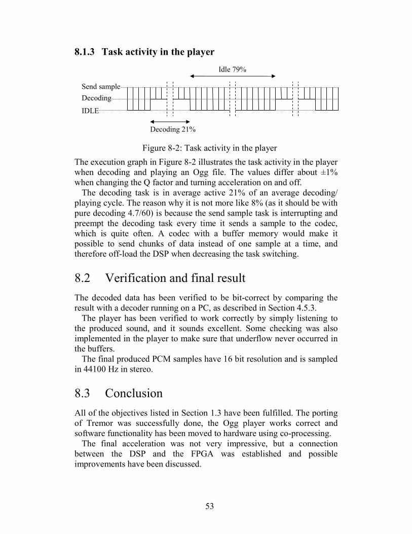
53
8.1.3 Task activity in the player
Figure 8-2: Task activity in the player
The execution graph in Figure 8-2 illustrates the task activity in the player
when decoding and playing an Ogg file. The values differ about ±1%
when changing the Q factor and turning acceleration on and off.
The decoding task is in average active 21% of an average decoding/
playing cycle. The reason why it is not more like 8% (as it should be with
pure decoding 4.7/60) is because the send sample task is interrupting and
preempt the decoding task every time it sends a sample to the codec,
which is quite often. A codec with a buffer memory would make it
possible to send chunks of data instead of one sample at a time, and
therefore off-load the DSP when decreasing the task switching.
8.2 Verification and final result
The decoded data has been verified to be bit-correct by comparing the
result with a decoder running on a PC, as described in Section 4.5.3.
The player has been verified to work correctly by simply listening to
the produced sound, and it sounds excellent. Some checking was also
implemented in the player to make sure that underflow never occurred in
the buffers.
The final produced PCM samples have 16 bit resolution and is sampled
in 44100 Hz in stereo.
8.3 Conclusion
All of the objectives listed in Section 1.3 have been fulfilled. The porting
of Tremor was successfully done, the Ogg player works correct and
software functionality has been moved to hardware using co-processing.
The final acceleration was not very impressive, but a connection
between the DSP and the FPGA was established and possible
improvements have been discussed.
IDLE
Decoding
Send sample
Decoding 21%
Idle 79%

54
This thesis project included many different technical fields and
challenging tasks that was quite time consuming for a single person, so
even though the acceleration in the end was not that remarkable this
project is considered to be successfully accomplished.
A conclusion one can make from this project with aspect to co-
processing is that it is very important to have a fast and effective
communication between processors so that no unnecessary bottlenecks
occurs.
When it comes to designing dedicated hardware for Ogg Vorbis
decoding using co-design with programmable logic, it is the authors
opinion that further research is unnecessary. There exists a number of
commercial low power Ogg Vorbis decoder chip2 on the market, most of
them are of ”system on a chip” type and consists of one single processor
(DSP or ARM based architecture) for decoding and player functions.
They are usually internally clocked at ~100-200 Mhz (using a PLL) and
have integrated peripherals like Digital to Analog Converters (DAC),
amplifiers, internal memory and accessibility to various external
memories, sometimes even USB and bluetooth support. Some chip have
support for more than just Ogg Vorbis, for example MP3, AAC and
WMA. Software optimizations have probably3 been made, but no
dedicated hardware (e.g a MDCT core) is used, it is too complicated, has
long time to market and cost too much.
2 Some examples:
VS1000 - http://www.vlsi.fi/vs1000/vs1000.shtml
STMP3600 - http://www.sigmatel.com/products/portable/audio/stmp3600.aspx
TCC72x - http://www.telechips.com/product/p_021.htm 3 It is documented that the VS1000 chip has removed floor 0 and limited the window sizes. No
information on other chip have been found.

55
Appendix A
Glossary
Atlantic Packet oriented data interface, developed by Texas
Instruments
ADC Analog to Digital Converter
ALU Arithmetic Logic Unit
API Application Programming Interface
ARM A processor architecture, previously, the Advanced RISC
Machine, and prior to that Acorn RISC Machine
BIOS Basic Input / Output System
Butterfly In the context of FFT algorithms, a butterfly is a
portion of the computation that combines the
results of smaller DFT into a larger DFT, or vice versa.
The name “butterfly” comes from the shape of the data-
flow diagram in the radix-2 case.
CCS Code Composer Studio
CPU Central Processing Unit
DAC Digital to Analog Converter
DFT Discrete Fourier transforms
DMA Direct Memory Access
DSK DSP Starter Kit

56
DSP Digital Signal Processor / Processning
EDMA Enhanced DMA controller
FFT Fast Fourier Transform
FIFO First In First Out
EMIF Extended Memory Interface
FIR Finite Impulse Response
FLAC Free Lossless Audio Codec
FPGA Field Programmable Gate Array
GNU Gnu is Not Unix
GPL General Public License
IDE Integrated Development Environment
IMDCT Inverse Modified Discrete Cosine Transform
JTAG Joint Test Action Group
LED Light Emitting Diode
MAC Multiply And Accumulate
MCU Micro Controller Unit
MDCT Modified Discrete Cosine Transform
MIPS Million Instructions Per Second
Ogg Open standard for a free container format for digital
multimedia.
PCM Pulse Code Modulation
ROM Read Only Memory
RTDX Real Time Data Exchange
SDRAM Synchronous Dynamic Random Access Memory
SRAM Static Random Access Memory
Tremor A integer-only Ogg Vorbis audio decoding library
VLIW Very Large Instruction Word

57
Vorbis An open source, lossy audio codec project headed by the
Xiph.Org Foundation. Commonly used in conjunction with
the Ogg container and is then called Ogg Vorbis.
Xiph.org A non-profit organization dedicated to producing public
domain multimedia formats and tools


59
Appendix B
Tremor License
Copyright (c) 2002, Xiph.org Foundation
Redistribution and use in source and binary forms, with or without
modification, are permitted provided that the following conditions are
met:
• Redistributions of source code must retain the above copyright notice, this list of conditions and the following disclaimer.
• Redistributions in binary form must reproduce the above copyright notice, this list of conditions and the following disclaimer in the
documentation and/or other materials provided with the distribution.
• Neither the name of the Xiph.org Foundation nor the names of its contributors may be used to endorse or promote products derived
from this software without specific prior written permission.
THIS SOFTWARE IS PROVIDED BY THE COPYRIGHT HOLDERS
AND CONTRIBUTORS ``AS IS'' AND ANY EXPRESS OR IMPLIED
WARRANTIES, INCLUDING, BUT NOT LIMITED TO, THE
IMPLIED WARRANTIES OF MERCHANTABILITY AND FITNESS
FOR A PARTICULAR PURPOSE ARE DISCLAIMED. IN NO
EVENT SHALL THE REGENTS OR CONTRIBUTORS BE LIABLE
FOR ANY DIRECT, INDIRECT, INCIDENTAL, SPECIAL,
EXEMPLARY, OR CONSEQUENTIAL DAMAGES (INCLUDING,
BUT NOT LIMITED TO, PROCUREMENT OF SUBSTITUTE
GOODS OR SERVICES; LOSS OF USE, DATA, OR PROFITS; OR
BUSINESS INTERRUPTION) HOWEVER CAUSED AND ON ANY
THEORY OF LIABILITY, WHETHER IN CONTRACT, STRICT
LIABILITY, OR TORT (INCLUDING NEGLIGENCE OR
OTHERWISE) ARISING IN ANY WAY OUT OF THE USE OF THIS
SOFTWARE, EVEN IF ADVISED OF THE POSSIBILITY OF SUCH
DAMAGE.


61
Bibliography
[1] Niklas Barsk, Ogg Vorbis Decoder For Motorola DSP56002,
Linköpings Tekniska Högskola, 2005
[2] Erik Montnémery, Johannes Sandvall, Ogg/Vorbis in embedded
systems, Lunds Tekniska Högskola, 2004
[3] Luis Azuara, Pattara Kiatisevi, Design of an Audio Player as
System-on-a-Chip, University of Stuttgart, 2002
Online: http://oggonachip.sourceforge.net/
[4] Xiph.Org Foundation
Online: http://xiph.org/
[5] Xiph.Org, Source code of Tremor (lowmem version)
Online: http://svn.xiph.org/branches/lowmem-branch/Tremor/
[6] T. Painter and A. Spanias. Perceptual coding of digital audio,
Proceedings of the IEEE, 88(4), april 2000
[7] Lars Wanhammar, DSP Integrated Circuits, Academic Press,
1999, ISBN: 0-12-734530-2
[8] D A Gwyn, alloca.c - allocate automatically reclaimed memory
(Mostly) portable public-domain implementation,
Online: http://www.mibsoftware.com/userkt/inn/dev/inn2.0-
beta/inn/lib/alloca.c
[9] Xiph.org Foundation, Ogg Vorbis I Specification,
Online: http://xiph.org/vorbis/doc/Vorbis_I_spec.pdf

62
[10] T.Sporer, K.Brandenburk, B.Edler, The use of multirate filter
banks for coding of high quality digital audio.
Proceedings of the 6th European Signal Processing Conference,
vol. 1, pages 211-214
[11] Texas Instruments, Code Composer Studio User’s Guide,
Section 5.1.2 Data File Format
Online: http://focus.ti.com/lit/ug/spru328b/spru328b.pdf
[12] Texas Instruments, TLV320AIC23, Stereo Audio CODEC, 8- to
96-kHz, With Integrated Headphone Amplifier, Data
Manual, 2002
Online: http://focus.ti.com/lit/ds/symlink/tlv320aic23.pdf
[13] Texas Instruments, Data sheet for: TMS320C6414,
TMS320C6415, TMS320C6416 Fixed-Point Digital Signal
Processors (Rev.N), 26 May 2005
Online: http://focus.ti.com/lit/ds/symlink/tms320c6416.pdf
[14] David Bell, Application Report, SPRA636A Applications Using
the TMS320C6000 Enhanced DMA, October 2001
Online: http://focus.ti.com/lit/an/spra636a/spra636a.pdf
[15] Spectrum Digital, Inc. TMS320C6416T DSK Technical
Reference, Rev A, November 2004
Online: http://c6000.spectrumdigital.com/dsk6416/V3/docs/dsk
6416_TechRef.pdf
[16] Altera Corporation, Application Note 363, ver. 1.1, FFT Co-
Processor Reference Design, May 2005
Online: http://www.altera.com/literature/an/an363.pdf
[17] Altera Corporation, Functional Specification 13, ver. 3.0,
Atlantic Interface, June 2002
Online: http://www.altera.com/literature/fs/fs_atlantic.pdf
[18] Altera Corporation, Stratix II Device Handbook, Volume 1
Online: http://www.altera.com/literature/hb/stx2/stratix2_hand
book.pdf

63
[19] Altera Corporation, Stratix II EP2S60 DSP Development Board,
Data Sheet, May 2005
Online: http://www.altera.com/literature/ds/ds_stratixII_dsp_
dev_board.pdf
[20] Wikipedia, Double Buffering
Online: http://en.wikipedia.org/wiki/Double_buffering
[21] Wikipedia, ARM architectur,
Online: http://en.wikipedia.org/wiki/ARM_architecture

På svenska
Detta dokument hålls tillgängligt på Internet – eller dess framtida ersättare –under en längre tid från publiceringsdatum under förutsättning att inga extra-ordinära omständigheter uppstår.
Tillgång till dokumentet innebär tillstånd för var och en att läsa, ladda ner,skriva ut enstaka kopior för enskilt bruk och att använda det oförändrat för ick-ekommersiell forskning och för undervisning. Överföring av upphovsrätten viden senare tidpunkt kan inte upphäva detta tillstånd. All annan användning avdokumentet kräver upphovsmannens medgivande. För att garantera äktheten,säkerheten och tillgängligheten finns det lösningar av teknisk och administrativart.Upphovsmannens ideella rätt innefattar rätt att bli nämnd som upphovsman i denomfattning som god sed kräver vid användning av dokumentet på ovan beskrivnasätt samt skydd mot att dokumentet ändras eller presenteras i sådan form eller isådant sammanhang som är kränkande för upphovsmannens litterära eller konst-närliga anseende eller egenart.
För ytterligare information om Linköping University Electronic Press se för-lagets hemsidahttp://www.ep.liu.se/
In English
The publishers will keep this document online on the Internet - or its possiblereplacement - for a considerable time from the date of publication barring excep-tional circumstances.
The online availability of the document implies a permanent permission foranyone to read, to download, to print out single copies for your own use and touse it unchanged for any non-commercial research and educational purpose. Sub-sequent transfers of copyright cannot revoke this permission. All other uses ofthe document are conditional on the consent of the copyright owner. The pub-lisher has taken technical and administrative measures to assure authenticity,security and accessibility.
According to intellectual property law the author has the right to be men-tioned when his/her work is accessed as described above and to be protectedagainst infringement.
For additional information about the Linköping University Electronic Pressand its procedures for publication and for assurance of document integrity, pleaserefer to its WWW home page:http://www.ep.liu.se/.
© Henric Kärnhall


