MACHINERY'S^-^ REFERENCE SERIES EACH NUMBER IS ONE UNIT IN A COMPLETE LIBRARY OF MACHINE DESIGN AND SHOP PRACTICE REVISED AND REPUB LISHED FROM MACHINERY No. 25 -DEEP HOLE DRILLING CONTENTS Introduction ------ . Principles of Deep Hole Drilling, by Lester G. French and C. L. Goodrich ------ Deep Hole Drilling in Gun Construction, by J. M. B. Scheele --------- Construction of Deep Hole Drills, by Frank B. Klein- hans, Otto Eckelt, and E. W. Norton Copyright, 1908, The Industrial Press, Publishers of Machinery, 49-55 Lafayette Street, New York City,
Transcript
MACHINERY'S^-^
REFERENCE SERIES
EACH NUMBER IS ONE UNIT IN A COMPLETE
LIBRARY OF MACHINE DESIGN AND SHOP
PRACTICE REVISED AND REPUB
LISHED FROM MACHINERY
No. 25 -DEEP HOLE DRILLING
CONTENTS
Introduction ------ .
Principles of Deep Hole Drilling, by Lester G. French
and C. L. Goodrich ------
Deep Hole Drilling in Gun Construction, by J. M. B.
Scheele ---------
Construction of Deep Hole Drills, by Frank B. Klein-
hans, Otto Eckelt, and E. W. Norton
Copyright, 1908, The Industrial Press, Publishers of Machinery,
49-55 Lafayette Street, New York City,
D36
INTRODUCTION.
The difficulties to be overcome in producing deep drilled holes can
be classified in three groups. In the first place the drill has a great
tendency to run out, thus producing a hole that is neither straight,
nor uniform in diameter; in the second place great difficulties are
encountered in trying to remove the chips in a satisfactory manner,
and in the third place the heating of the cutting tool is difficult to
prevent.
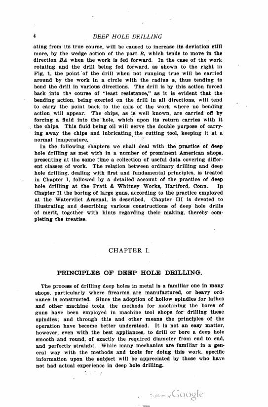
Fig. 1. Comparison between Action of Cutting Toolwhen Drill and when Work revolves.
The principle involved in common drill presses where the drill is
given a rotary motion simultaneously with the forward motion for
feeding is the one least adapted to produce a straight and true hole.
Better results are obtained by giving only a rotary motion to the
drill, and feeding the work toward it. It has been found, however,
that for drilling deep holes the reversal of this, that is, imparting a
rotary motion to the work, and the feed motion to the drill will
answer the purpose still better. It seems as if there could be no
material difference between the latter two methods. An analysis of
the conditions involved will show, however, that there is a decided
difference in the action of the drill. If the drill rotates, and the work
is fed forward as shown to the left in Fig. 1, the drill, when devi
4 DEEP HOLE DRILLING
ating from its true course, will be caused to increase its deviation still
more, by the wedge action of the part B, which tends to move in the
direction BA when the work is fed forward. In the case of the work
rotating and the drill being fed forward, as shown to the right in
Fig. 1, the point of the drill when not running true will be carried
around by the work in a circle with the radius a, thus tending to
bend the drill in various directions. The drill is by this action forced
back into th^ course of "least resistance," as it is evident that the
bending action, being exerted on the drill in all directions, will tend
to carry the point back to the axis of the work where no bending
action, will appear. The chips, as is well known, are carried off by
forcing a fluid into the ' hole, which upon its return carries with it
the chips. This fluid being oil will serve the double purpose of carry
ing away the chips and lubricating the cutting tool, keeping it at a
normal temperature.
In the following chapters we shall deal with the practice of deep
hole drilling as met with in a number of prominent American shops,
presenting at the same time a collection of useful data covering differ
ent classes of work. The relation between ordinary drilling and deep
hole drilling, dealing with first and fundamental principles, is treated
in Chapter I, followed by a detailed account of the practice of deep
hole drilling at the Pratt & Whitney Works, Hartford, Conn. In
Chapter II the boring of large guns, according to the practice employed
at the Watervliet Arsenal, is described. Chapter III is devoted to
illustrating and describing various constructions of deep hole drills
of merit, together with hints regarding their making, thereby com
pleting the treatise.
CHAPTER I.
PRINCIPLES OF DEEP HOLE DRILLING.
The process of drilling deep holes in metal is a familiar one in many
shops, particularly where firearms are manufactured, or heavy ord
nance is constructed. Since the adoption of hollow spindles for lathes
and other machine tools, the methods for machining the bores of
guns have been employed in machine tool shops for drilling these
spindles; and through this and other means the principles of the
operation have become better understood. It is not an easy matter,
however, even with the best appliances, to drill or bore a deep hole
smooth and round, of exactly the required diameter from end to end,
and perfectly straight. While many mechanics are familiar in a gen
eral way with the methods and tools for doing this work, specific
information upon the subject will be appreciated by those who have
not had actual experience in deep hole drilling.
GENERAL PRINCIPLES 5
It is well known that a long, or deep, hole—that is, one long in
proportion to its diameter—is best roughed out and finished by using
a tool on the end of a long bar which enters the work from one end.
This is true, whether drilling into solid metal, or boring and reaming
a hole that has already been drilled or bored out. A boring bar which
extends through the piece, and on which is either a stationary or a
traveling head, is not satisfactory for very long work, owing to the
spring and deflection cf the bar, which is made worse by the fact that
the bar must be enough smaller than the bore to allow room for the
cutter head. While a long hole may sometimes be finished satisfactorily
by means of such a boring bar, by packing the cutter head with
wooden blocks which just fill the part of the bore that has been
machined, and so support the bar, the method is fundamentally incor
rect for long work.
The best methods for machining deep holes are nothing more nor
less than an adaptation of what has been found successful in ordinary
drilling and boring in the engine lathe or chucking machine. We will
therefore first discuss certain types of chucking tools and drills, and
show their relationship to tools that may be used for deep hole drill
ing.
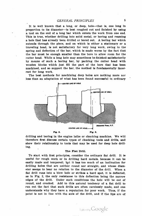
To start with first principles, consider the ordinary flat drill. It Is
useful for rough work or in drilling hard metals, because it can be
easily made and tempered; but it has too much of an inclination for
drilling holes that are neither round nor straight, and whose diam
eter seems to bear no relation to the diameter of the drill. When a
flat drill runs into a blow hole or strikes a hard spot, it is deflected,
as in Fig. 2, the only resistance to this deflection being the narrow
edges of the drill. Under such conditions the hole will be out of
round, and crooked. Add to this natural tendency of a flat drill to
run out the fact that such drills are often carelessly made, and one
understands why they have a reputation for poor work. Thus, if the
point is not in line with the axis of the drill, and if the lips are of
Indu»trial I'rtt, XT.
CENTER LINE OF HOt
PiK. 2. Fig. 3.
The Flat Drill.
6 DEEP HOLE DRILLING
unequal length, or do not make equal angles with the axis, the hole
will be larger than the drill diameter. This is illustrated in Fig. 3,
where one lip is longer than the other, and the point does not lie in
the central axis of the drill. The tendency of the drill is to rotate
about its point, and thus the axis will move in a small circle about
this point, causing the hole to be of larger diameter than the drill.
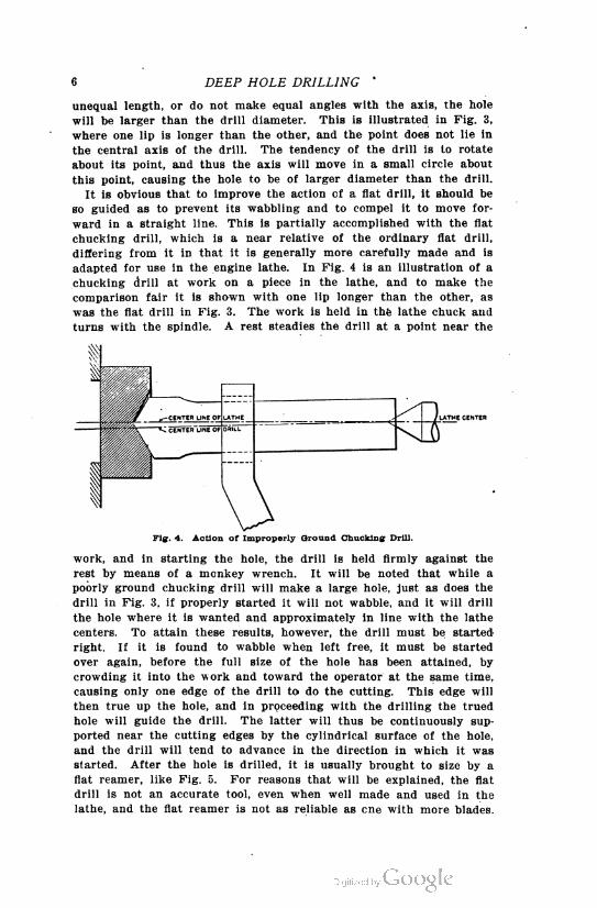
It is obvious that to improve the action of a flat drill, it should be
so guided as to prevent its wabbling and to compel it to move for
ward in a straight line. This is partially accomplished with the flat
chucking drill, which is a near relative of the ordinary flat drill,
differing from it in that it is generally more carefully made and is
adapted for use in the engine lathe. In Fig. 4 is an illustration of a
chucking drill at work on a piece in the lathe, and to make the
comparison fair it is shown with one lip longer than the other, as
was the flat drill in Fig. 3. The work is held in the lathe chuck and
turns with the spindle. A rest steadies the drill at a point near the
Fig. 4. Action of Improperly Ground Chucking Drill.
work, and in starting the hole, the drill is held firmly against the
rest by means of a monkey wrench. It will be noted that while a
poorly ground chucking drill will make a large hole, just as does the
drill in Fig. 3, if properly started it will not wabble, and it will drill
the hole where it is wanted and approximately in line with the lathe
centers. To attain these results, however, the drill must be started
right. If it is found to wabble when left free, it must be started
over again, before the full size of the hole has been attained, by
crowding it into the work and toward the operator at the same time,
causing only one edge of the drill to do the cutting. This edge will
then true up the hole, and in proceeding with the drilling the trued
hole will guide the drill. The latter will thus be continuously sup
ported near the cutting edges by the cylindrical surface of the hole,
and the drill will tend to advance in the direction in which it was
started. After the hole is drilled, it is usually brought to size by a
flat reamer, like Fig. 5. For reasons that will be explained, the flat
drill is not an accurate tool, even when well made and used in the
lathe, and the flat reamer is not as reliable as cne with more blades.
GENERAL PRINCIPLES 7
The general principle, however, of first starting with a true hole,
and then having the drill body designed to follow in its path and
so guide the cutting edges, is the fundamental principle of deep hole
drilling.
Fig. 6 shows how a flat drill may be adapted for deep hole drilling.
The drill from which the illustration was made was employed for
drilling a four-inch hole through steel rolls seven feet long. Instead
of depending upon the narrow edges of the drill proper to guide and
support the cutting edges, the cutting edges are formed on a blade
inserted in a cylindrical cast-iron head, the outside diameter of which
is turned to a sliding fit in the hole that is being bored. The cutting
edges are grooved to break up the chips, enabling the latter to pass
out through the passage E, on each side of the head. The grooves
Pig. 5. Plat Reamer.
are laid out so that those in one blade come opposite to the lands in
the other blade. In the illustration, A is the cutter, B one of the
screws holding the cutter to the head C, and the head is attached
to the bar by the shank D.
The Twist Drill.
The modern twist drill accomplishes all that is attained by the
arrangement in Fig. 6, and in addition can be ground without seri
ously affecting the rake, and will free itself from chips more readily,
owing to its spiral flutes. The lands of a twist drill present a large
cylindrical surface to bear against the sides of the hole and take the
side thrust. If the drill is also guided by a hardened bushing, at
the point where it enters the metal, as in the case of jig work, the
drill will have very little chance to deflect, and the hole will be accu
rately located and will be quite true and straight.
The twist drill in a modified form is also employed for deep hole
drilling. The hollow drill introduced by the Morse Twist Drill Co.,
New Bedford, Mass., is adapted for this purpose, and in Fig. 7 is
shown the arrangement recommended by this company for feeding
this drill into the work. The drill has a hole lengthwise through the
shank, connecting with the grooves in the drill, as indicated. The
shank can be threaded and fitted to a metal tube which acts as a
boring bar and through which the chips and oil may pass from the
point of the drill. Oil is conveyed to the point on the outside of the
tube, as shown in Fig. 7.
In using the hollow drill, the hole is first started by means of a
8 DEEP HOLE DRILLING
short drill of the size of the hole desired, and drilled to a depth
equal to the length of the hollow drill to be employed. The body of
the hollow drill acts as a stuffing, compelling the oil to follow the
oil grooves provided, and the chips to flow out through the flutes
and the hollow shank. The methods of supporting and driving the
work, and of feeding the drill, are clearly shown in Fig. 7. Drills of
this type are regularly manufactured in sizes up to three inches in
diameter, and it is stated that the best results are obtained, when
drilling tool steel, by revolving the drill at a cutting speed of 20 feet
per minute, with a feed of 0.0025 inch per revolution, while machine
steel will admit of a cutting speed of 40 feet per minute and a feed
of 0.0035 inch per revolution.
Number of Cutting- Edges Desirable.
When drilling a hole out of solid stock, some type of drill having
two lips or cutting edges is usually the most feasible, and probably
nothing will be devised that on the whole surpasses the twist drill
Ag c
\A 0B ^
D
\
Ti E
Induttrial Prt»», X. Y.
Fig. 6. Flat Drill with Inserted Blade for Deep Drilling.
for such work. As is well known, the ordinary twist drill is always
provided with two flutes, but twist drills having three or more flutes
have been devised, made and tried. The advantages gained by add
ing to the number of cutting edges have, however, not been great
enough to justify the increased cost of manufacture. When added
to this comes the weakness caused by the increased number of grooves,
and the complicated operation of correctly grinding such drills, it is
clear "why drills having two flutes only have been and should be
adopted.
An end mill, like that in Fig. 11, can be used for drilling, if it
has a "center cut," and it will presently be explained how a tool
with a single cutting edge may be advantageously employed, particu
larly for deep hole drilling. The familiar D-drill is of this type,
and also its modification as used by the Pratt & Whitney Co. in drill
ing gun barrels.
When it comes to truing up or enlarging a hole previously drilled
or bored, the two-lip drill is not suitable in any of its forms. For
boring a true hole nothing can surpass a single-pointed boring tool,
the ideal condition for finishing a hole being when the cutting point
is a real diamond, or a rotating wheel of abrasive material.
It is obvious that when a hard or soft spot is encountered in boring
GENERAL PRINCIPLES
10 DEEP HOLE DRILLING
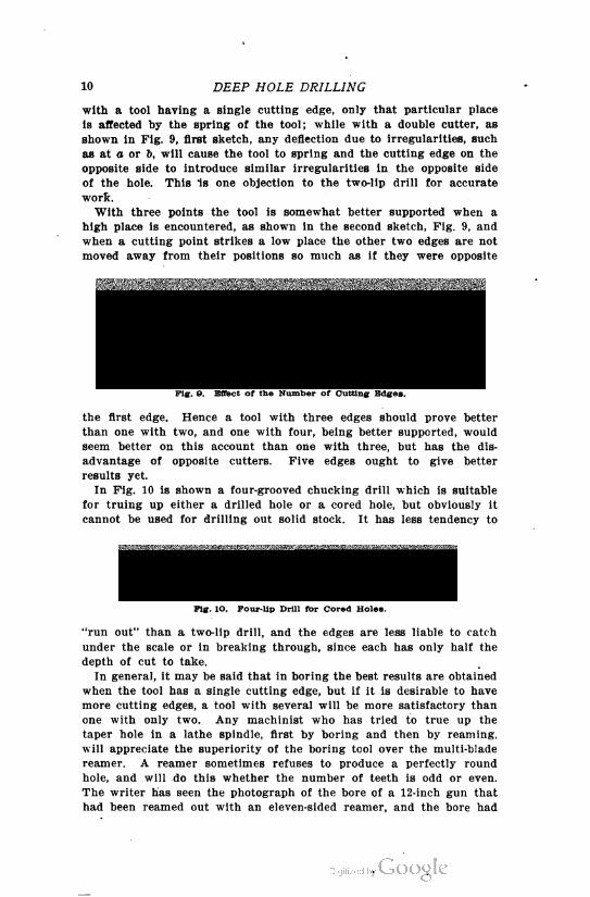
with a tool having a single cutting edge, only that particular place
is affected by the spring of the tool; while with a double cutter, as
shown in Fig. 9, first sketch, any deflection due to irregularities, such
as at a or 6, will cause the tool to spring and the cutting edge on the
opposite side to introduce similar irregularities in the opposite side
of the hole. This Is one objection to the two-lip drill for accurate
work.
With three points the tool is somewhat better supported when a
high place is encountered, as shown in the second sketch, Fig. 9, and
when a cutting point strikes a low place the other two edges are not
moved away from their positions so much as if they were opposite
Induitriil I'rw. S.Y.
Fig. O. Effect of the Number of Cutting Edges.
the first edge. Hence a tool with three edges should prove better
than one with two, and one with four, being better supported, would
seem better on this account than one with three, but has the dis
advantage of opposite cutters. Five edges ought to give better
results yet.
In Fig. 10 is shown a four-grooved chucking drill which is suitable
for truing up either a drilled hole or a cored hole, but obviously it
cannot be used for drilling out solid stock. It has less tendency to
Induttrial Prw. A'.f".
Fig. lO. Four-lip Drill for Cored Holes.
"run out" than a two-lip drill, and the edges are less liable to catch
under the scale or in breaking through, since each has only half the
depth of cut to take.
In general, it may be said that in boring the best results are obtained
when the tool has a single cutting edge, but if it is desirable to have
more cutting edges, a tool with several will be more satisfactory than
one with only two. Any machinist who has tried to true up the
taper hole in a lathe spindle, first by boring and then by reaming,
will appreciate the superiority of the boring tool over the multi-blade
reamer. A reamer sometimes refuses to produce a perfectly round
hole, and will do this whether the number of teeth is odd or even.
The writer has seen the photograph of the bore of a 12-inch gun that
had been reamed out with an eleven-sided reamer, and the bore had
GENERAL PRINCIPLES 11
eleven distinct sides, clearly visible in the photograph. The trouble
was overcome by spacing the reamer, teeth unequally.
Advantages of the End Cut.
One trouble with reamers, however, is that the teeth necessarily
cut on their side edges instead of on their ends, and the whole effect
of any unevenness in the hole is to crowd the reamer to one side.
The condition exists to a less extent with a flat or twist drill, where
the cutting edges are at an angle with the center line, and the result
ant of any unusual pressure is felt partly as a side thrust and partly
as an end thrust. Now, by making a drill to cut squarely on its
end and but very little, or not at all, on its sides, the side thrust
is mostly done away with. The end mill shown in Fig. 11 is a good
illustration of such a tool, and it is known to be capable of boring
very accurate holes when used for that purpose in the milling machine.
In Fig. 12 is a boring tool with a single cutting edge, which cuts
on its end and is capable of drilling a true hole in solid metal. It
consists of a round tool steel bar, with one end flattened and ground
to form a cutting edge, as shown. It is designed to be held in the
tool-post of the lathe, in a position perpendicular to the face-plate.
Induttrial Pmt, A'. J'.
Fig. 11. End Mill with Center Cut, suitable for Accurate Drilling.
The inner edge or corner of the cutting edge should be slightly
rounded to help support the cutter and prevent chattering, and the
width A of the cutting edge should be from 1/32 to 1/16 inch less
than the radius of the hole to be drilled. The objection to this tool
is that it cannot be supported stiffly enough by the tool-post for a
hole of great depth, and for this purpose the D-drill shown in Fig. 13,
and which works on the same principle, is well adapted. In its sim
plest form it consists of a round bar of the diameter of the hole to be
drilled, one-quarter to one-half of which is milled out to give a pas
sage for the chips. The end of the bar is shaped with a cutting
edge on one side', extending almost or quite to the center, and with
the other side relieved to give clearance for the cutter. Such a drill
should be supported by a bearing close to the hole to be bored, in
case it is to start the hole itself, and it is better yet to start the
hole with a twist drill and true it up with a single-pointed boring
tool, and then let the drill be guided by this hole. This is the surest
way of getting a hole concentric with the axis of the lathe. As the
bar is of the same diameter as the hole, the cutter will be supported
by one-half the surface of the hole, and if it is once started right in
an accurate hole, it will continue in the right direction.
It is desirable to have the cutter blade separated from the bar or
head, as the case may be, so that it may be renewed or removed for
12 DEEP HOLE DRILLING
grinding, particularly in drilling large holes. In Fig. 8 is an iilustra-
tion of such a cutter head as used by a large ship- and engine-building
concern, in drilling propeller shafts. The body of the cutter is made
from soft steel with tool steel strips x dove-tailed in and ground in
place to size. The cutters are made by jigs and are interchangeable,
and their shape is such as to break up the chips, which are washed
Fig-. 12. Boring Tool with the Cutting- Edge on the End.
out by the force of oil supplied by a pump, through the hollow bor
ing bar, to which this cutter head is fastened. One of these cutters,
four inches in diameter, has bored 12 inches in a piece of nickel steel
in one hour, cutting a fair and smooth hole, and no trouble has ever
occurred, even when holes have been drilled to a depth of 32 feet.
Rotating' Work vs. Rotating Drill.
In deep hole drilling it is customary to have the drill fixed so that
it cannot turn, and rotate the work, following the usual method in this
respect for boring accurate holes in the lathe. Since the outer end
of the work can be supported in the center rest, it is always possible
to make the work run true, while it is not so easy to make a drill run
true and coincident with the axis of the work. The difference in
principle involved has already been explained in the introduction,
and shown graphically in Fig. 1.
Deep Hole Drilling Attachment for the Lathe.
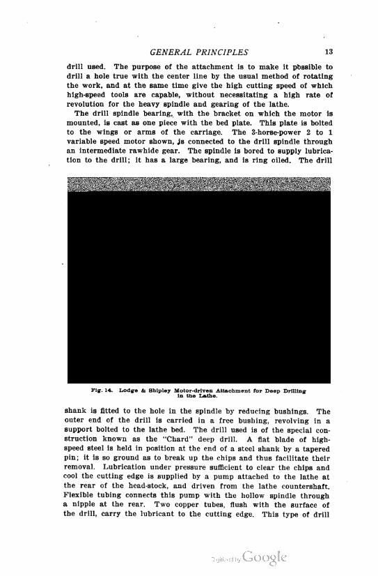
An attachment is shown in Fig. 14 for performing deep drilling
rapidly and economically on the engine lathe. This attachment is
built by the Lodge & Shipley Machine Tool Co., Cincinnati, Ohio. It
Pig-. 13. D-Drill ueed for Deep Drilling.
consists essentially of a drill spindle, mounted on the cross-slide in
place of the usual tool-post, in combination with an electric motor
and suitable gearing for rotating the spindle. A support is provided
for holding the outer end of the work, the other end of which is
clamped in the chuck or face-plate of the lathe. Provision is also
made for forcing a copious supply of lubricant to the point of the
GENERAL PRINCIPLES 13
drill used. The purpose of the attachment is to make it possible to
drill a hole true with the center line by the usual method of rotating
the work, and at the same time give the high cutting speed of which
high-speed tools are capable, without necessitating a high rate of
revolution for the heavy spindle and gearing of the lathe.
The drill spindle bearing, with the bracket on which the motor is
mounted, is cast as one piece with the bed plate. This plate is bolted
to the wings or arms of the carriage. The 3-horse-power 2 to 1
variable speed motor shown, js connected to the drill spindle through
an intermediate rawhide gear. The spindle is bored to supply lubrica
tion to the drill; it has a large bearing, and is ring oiled. The drill
Fig. 14. Lodge & Shipley Motor-driven Attachment for Deep Drillingin the Lathe.
shank is fitted to the hole in the spindle by reducing bushings. The
outer end of the drill is carried in a free bushing, revolving in a
support bolted to the lathe bed. The drill used is of the special con
struction known as the "Chard" deep drill. A flat blade of high
speed steel is held in position at the end of a steel shank by a tapered
pin; it is so ground as to break up the chips and thus facilitate their
removal. Lubrication under pressure sufficient to clear the chips and
cool the cutting edge is supplied by a pump attached to the lathe at
the rear of the head-stock, and driven from the lathe countershaft.
Flexible tubing connects this pump with the hollow spindle through
a nipple at the rear. Two copper tubes, flush with the surface of
the drill, carry the lubricant to the cutting edge. This type of drill
14 DEEP HOLE DRILLING
has been in use for some time on lathe spindles, back gear sleeves
and pulley sleeves. Under favorable conditions a 2-inch drill has
been advanced at the rate of 2*4 inches per minute. The drill is
illustrated and described in Chapter III.
This whole attachment may be easily removed from the carriage
by the use of an over-head crane, suitable I-bolts being provided for
this purpose. Only a few minutes time is required to change the
machine over for engine lathe work. The particular device illus
trated is used regularly for drilling holes in locomotive driving axles,
the holes being 1 inch in diameter and 44 inches deep.
Drilling Deep Holes by the Pratt & Whitney Method.
A highly satisfactory drill for use in drilling deep holes is one
brought out by the Pratt & Whitney Co., principally for use in connec
tion with their gun-barrel drilling machines. The tool in question is
a development of the old D or hog-nose drill, already described, which
has one cutting lip only. It is carefully ground on the outside, and is
supplied with an oil duct through which oil at high pressure may be
brought directly to the cutting edge.
Referring to Fig. 15, A is the cutting edge, B the oil duct, and C
the chip groove. In milling the latter groove, the cutter is brought
directly to the center line, so that in this respect the drill is very
free cutting as compared with the ordinary two-lip twist drill which
has a central web. In the end view, the shape of the chip groove is
clearly indicated. The cutting edge A is radial. In sharpening the
drill, the high point or part first entering the work is not ground
in the center as is usually the case in drills, but to one side as shown
in Fig. 15, in which D is a cross-section of the work being drilled,
and E the high point of the drill. Grinding the drill in this manner
makes possible its running true or straight, the teat F on the work
acting as a support to the drill, which, owing to its periphery being
partly relieved, would have a tendency to travel in a curve away
from its cutting side. The piece being drilled is run at very high
speed, the periphery speed at the outer diameter of the hole being as
high as 130 feet per minute on machine steel. The feed, however, is
quite fine, on a 0.3-inch drill averaging 0.0004 inch per revolution,
while on a 3-inch drill it is about 0.0008 inch. These figures, of course,
are dependent to a great extent on the material being drilled. The
drills are made of high-grade steel and left very hard, so that the
fine feed has little tendency to glaze the cutting edge.
The piece being drilled is held and revolved at one end by a suit
able chuck on the live spindle of the machine, while the other end,
which should be turned perfectly true, runs in a stationary bushing
having at its outer end a hole the diameter of the drill. The drill
enters the work through the bushing, and is thus started perfectly
true. The arrangement is indicated in the upper view in Fig. 16, in
which A represents the chuck, B the work, C the bushing, D the sup
port for holding the bushing, and E the drill. Through the oil duct
of the drill, oil is forced at a pressure varying from 150 to 200 pounds
GENERAL PRINCIPLES 15
per square inch. After passing the cutting edge, the oil returns to
the reservoir by the way of the chip groove, forcing the chips along
in its travel. In drills of large diameter, especially when working
on tough, stringy material, the cutting edge is usually ground so as
to produce a number of shavings, instead of one the full width of the
E
Fig. 16. Pratt & Whitney Co.'s Deep Hole Drill.
cutting lip, so that no trouble is experienced in getting chips out of
the way. The oil, of course, is used over and over again, and with
a large reservoir will be kept quite cool.
The drill is made up of the drill tip and shank, the tip varying in
length from 4 inches to 8 inches, while the length of shank is deter
mined by the depth of hole that is to be drilled. The lower view in
Fig. 16 will clearly illustrate the construction of a small, complete
drill, A being the tip, C the shank, and D the oil duct. The shanks
on small drills are made from steel tubing, rolled as shown in the
a
>
Fig. 16. Arrangement for starting the Deep Hole Drill, andMethod of Fastening Shank to Drill.
cross-section at the right-hand end. The tip is carefully fitted and
soldered to the shank, which, it should be noted, is a little smaller
in diameter than the tip.
The relief or clearance of the cutting edge of the drill, the amount
the "high point" of the drill should be off center, and the number
of rings on the end of the drill, when provided with notches for break
ing up the chips, depend entirely upon the material that is to be
drilled. For instance, on very soft stock, the supporting teat should
16 DEEP HOLE DRILLING
be more substantial than on hard spindle or gun steel, so that it is '
evident that on soft stock the high point should be more off center,
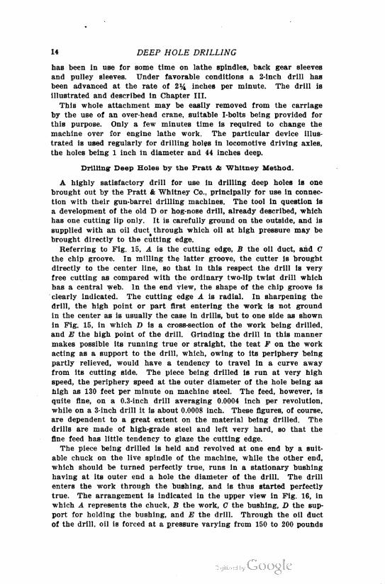
or nearer to the outer diameter, than on hard stock. Figs. 17 and 18
are reproductions from actual photographs of a 3-inch drill, and the
Figs. IT and 18. Side and End View of Deep Hole Drill.
reader will obtain a very clear idea from the engravings of the appear
ance of the tool described. These figures illustrate a drill ground on
the end so as to produce several shavings.
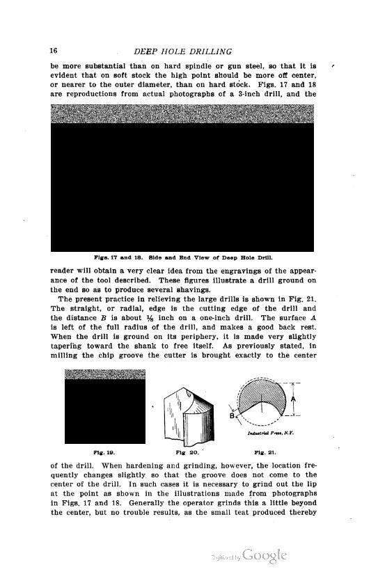
The present practice in relieving the large drills is shown in Pig. 21.
The straight, or radial, edge is the cutting edge of the drill and
the distance B is about % inch on a one-inch drill. The surface A
is left of the full radius of the drill, and makes a good back rest.
When the drill is ground on its periphery, it is made very slightly
tapering toward the shank to free itself. As previously stated, in
milling the chip groove the cutter is brought exactly to the center
Fig. 19. Fig 20. ' Pig. 21.
of the drill. When hardening and grinding, however, the location fre
quently changes slightly so that the groove does not come to the
center of the drill. In such cases it is necessary to grind out the lip
at the point as shown in the illustrations made from photographs
in Figs. 17 and 18. Generally the operator grinds this a little beyond
the center, but no trouble results, as the small teat produced thereby
GENERAL PRINCIPLES
18 SDEEP HOLE DRILLING
is broken off when the bottom of the ground out place Comes in con
tact with the end of the teat, as indicated in Figs. 19 and 20.
In Fig. 22 is an engraving of one size of a tube and gun-barrel drill
ing machine, as built by the Pratt & Whitney Co., Hartford, Conn.
This machine, while primarily designed for drilling gun barrels, is
adapted for any class of deep hole drilling, such as hollow spindles,
etc. The machine is provided with a double head, the heads being
placed side by side at one end as shown; independent spindles are
mounted in each head. On their inner ends are chucks for securing
and rotating the work, which is also supported by split bushings
carried in rests on the bed. The drills are carried by the carriages,
and fed positively by power feed. This feed is variable, to provide
for different qualities of stock to be drilled. Two rotary pumps, one
for each head, force oil, supplied from a tank placed underneath
the machine, through a series of tubes into and through the drill.
The oil lubricates the cutting lip and forces out the chips into the
basin on the top of the tank, where they are drained, and from where
the strained oil is returned to the tank again.
Attention should also be called to the method employed for drilling
oil holes in so-called oil twist drills. These holes are drilled before
the drill is fluted, the drills afterwards being rough fluted with
straight flutes, the drill then twisted, and finally finished in the usual
manner. The drilling of the oil holes is done progressively by small
twist drills, arranged in order of length, each drill deepening the
hole made by its predecessor only % or % inch. The hole is begun
by a short stiff drill which starts the hole perfectly true, and the
following drills are guided by the sections of the hole first drilled.
This practice eliminates the use of a long, slender drill for drilling
the first part of the hole, and enables the drilling to be done much
faster than would otherwise be possible.
CHAPTER II.
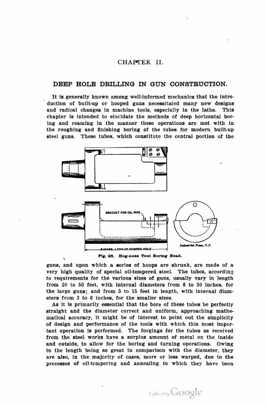
DEEP HOLE DRILLING IN GUN CONSTRUCTION.
It is generally known among well-informed mechanics that the intro
duction of built-up or hooped guns necessitated many new designs
and radical changes in machine tools, especially in the lathe. This
chapter is intended to elucidate the methods of deep horizontal bor
ing and reaming in the manner these operations are met with in
the roughing and finishing boring of the tubes for modern built-up
steel guns. These tubes, which constitute the central portion of the
Iitduatriat PrW, KT.-3-DIAMS—LONG-OF-C
Fig. 23. Hog-nose Tool Boring Head.V
guns, and upon which a series of hoops are shrunk, are made of a
very high quality of special oil-tempered steel. The tubes, according
to requirements for the various sizes of guns, usually vary in length
from 20 to 50 feet, with internal diameters from 6 to 30 inches, for
the large guns; and from 5 to 15 feet in length, with internal diam
eters from 3 to 6 inches, for the smaller sizes.
As it is primarily essential that the bore of these tubes be perfectly
straight and the diameter correct and uniform, approaching mathe
matical accuracy, it might be of interest to point out the simplicity
of design and performance of the tools with which this most impor
tant operation is performed. The forgings for the tubes as received
from the steel works have a surplus amount of metal on the inside
and outside, to allow for the boring and turning operations. Owing
to the length being so great in comparison with the diameter, they
are also, in the majority of cases, more or less warped, due to the
processes of oil-tempering and annealing to which they have been
20 DEEP HOLE DRILLING
subjected. After having ascertained the amount of existing warp and
having investigated the concentricity of the inner and outer circum
ferences, the tube is centered and -spotted in a special lathe desig
nated for the purpose, preparatory to the first rough boring. The
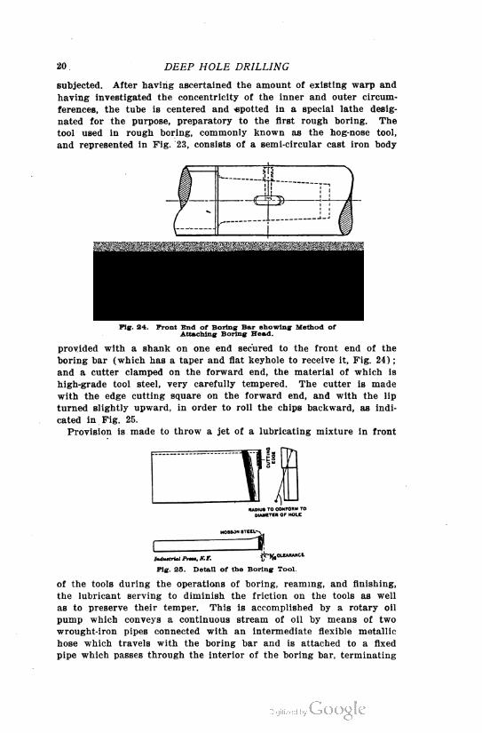
tool used in rough boring, commonly known as the hog-nose tool,
and represented in Fig. 23, consists of a semi-circular cast iron body
I Indu»trial Prtee. A'. J\
Fig. 24. Front End of Boring Bar showing Method ofAttaching Boring Head.
provided with a shank on one end secured to the front end of the
boring bar (which has a taper and fiat keyhole to receive it, Fig. 24);
and a cutter clamped on the forward end, the material of which is
high-grade tool steel, very carefully tempered. The cutter is made
with the edge cutting square on the forward end, and with the lip
turned slightly upward, in order to roll the chips backward, as indi
cated in Fig. 25.
Provision is made to throw a jet of a lubricating mixture in front
RADIUS TO CONFORM TODIAMETER OF HOLE
HOB80N STEEL-
MMIAnM " ^.CLEARARCE
Pig. 25. Detail of the Boring Tool
of the tools during the operations of boring, reaming, and finishing,
the lubricant serving to diminish the friction on the tools as well
as to preserve their temper. This is accomplished by a rotary oil
pump which conveys a continuous stream of oil by means of two
wrought-iron pipes connected with an intermediate flexible metallic
hose which travels with the boring bar and is attached to a fixed
pipe which passes through the interior of the boring bar, terminating
22 DEEP HOLE DRILLING
at the end of the cutting tools. The pump is provided with different
changes of speed.
Although this tool, because of its design, is capable of removing a
considerable quantity of metal, it has proved most practical not to
allow it (though this is seldom required) to remove more than from
0.2 to 0.5 inch of metal on the side, leaving approximately 0.01 inch
to be removed by the reaming and finishing tool in the succeeding op
erations.
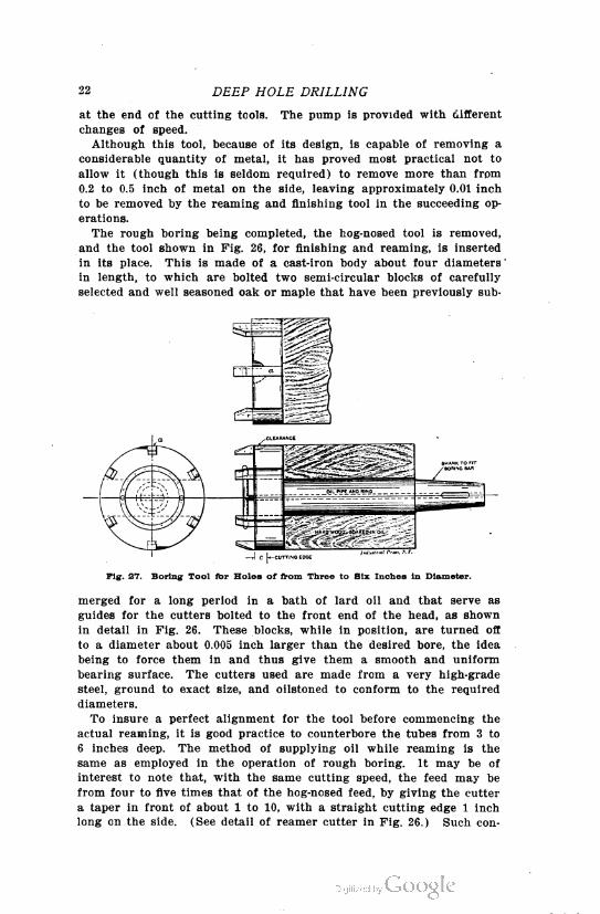
The rough boring being completed, the hog-nosed tool is removed,
and the tool shown in Fig. 26, for finishing and reaming, is inserted
in its place. This is made of a cast-iron body about four diameters
in length, to which are bolted two semi-circular blocks of carefully
selected and well seasoned oak or maple that have been previously sub
merged for a long period in a bath of lard oil and that serve as
guides for the cutters bolted to the front end of the head, as shown
in detail in Fig. 26. These blocks, while in position, are turned off
to a diameter about 0.005 inch larger than the desired bore, the idea
being to force them in and thus give them a smooth and uniform
bearing surface. The cutters used are made from a very high-grade
steel, ground to exact size, and oilstoned to conform to the required
diameters.
To insure a perfect alignment for the tool before commencing the
actual reaming, it is good practice to counterbore the tubes from 3 to
6 inches deep. The method of supplying oil while reaming is the
same as employed in the operation of rough boring. It may be of
interest to note that, with the same cutting speed, the feed may be
from four to five times that of the hog-nosed feed, by giving the cutter
a taper in front of about 1 to 10, with a straight cutting edge 1 inch
long on the side. (See detail of reamer cutter in Fig. 26.) Such con-
24 DEEP HOLE DRILLING
struction also serves to maintain the size in case the forward part
of the cutter becomes slightly worn.
Multiple cutter wood reamers, illustrated in Fig. 27, have been
sucessfully used for bores of from 3 to 6 inches calipers, for lengths
varying from 5 to 15 feet. Greater feed can be employed with tools
thus constructed, and consequently considerable time is saved by
their use. It must be borne in mind, however, that in tubes of great
length, in which there is an unequal distribution of stock on the in
terior, these tools have a tendency to run out of their true axis, thus
leaving an unsymmetrical bore. This difficulty is obviated, and a per
fect and uniform bore obtained, by the use of the previously described
hog-nosed tool and wood-lined reamer, although some time is sacri
ficed owing to the reduced feeds at which they have to be run com
pared with the feeds obtainable with a multiple cutter wood reamer.
In boring guns, lathes are employed which are specially designed
for the purpose. Nevertheless, if such a machine is not available, for
short lengths and small bores, it is advisable to use the old and well-
known method of attaching to the cross-slide of a common lathe of
suitable length of bed a fixed support or bracket having a bore to
receive a number of bushes, the bores of which correspond to the
varying diameters of boring bars. The hub of this support or bracket
has one side split to enable it to be tightened by a bolt, in order to
retain and grip the bushing which is likewise split for the purpose
of gripping the boring bar. The boring and reaming tools shown in
the engravings, Pigs. 27 and 28, are particularly applicable in this case.
After having determined the required feed and set the lathe in motion,
the carriage will serve to feed the bar in the usual manner. The
other functions are performed in the ordinary way and are too obvious
for further explanation.
Machines Employed in Boring Large Guns.
While, as just mentioned, any lathe may be employed for deep-hole
drilling, when large guns are bored, use is made of machines especially
designed for the purpose. In the following is shown and described
the general design of the boring and turning lathe employed at the
Government Army Gun Factory, at Watervliet Arsenal, N. Y., for per
forming the necessary operations in connection with a 16-inch breech-
loading rifle. Of course, only the most characteristic features of this
huge lathe can be dwelt upon.
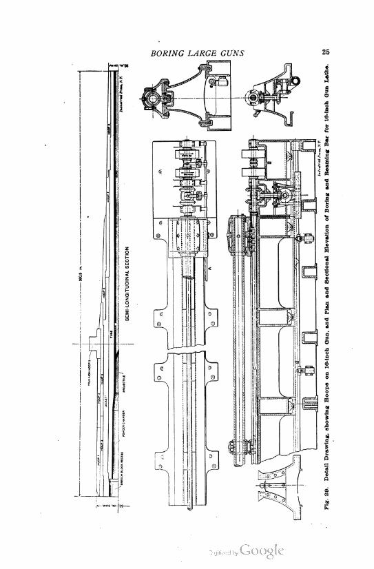
Before entering upon a description of the lathe, however, a few
explanatory words with reference to the gun constructed may be in
place. The semi-longitudinal section in the upper part of Fig. 29
will serve to explain the method of assembling the built-up or hooped .
gun, which is composed of several parts united to form a whole. The
parts are properly arranged to support the stresses upon them, and
the gun has therefore been termed "built-up or hooped." These parts
are assembled according to modern practice adopted by the ordnance
department, for which purpose the army gun factory is equipped with
specially-designed oil and high-pressure steam shrinkage furnaces.
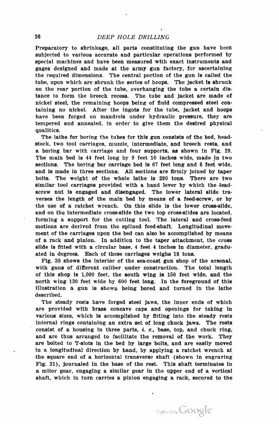
26 DEEP HOLE DRILLING
Preparatory to shrinkage, all parts constituting the gun have been
subjected to various accurate and particular operations performed by
special machines and have been measured with exact instruments and
gages designed and made at the army gun factory, for ascertaining
the required dimensions. The central portion of the gun is called the
tube, upon which are shrunk the series of hoops. The jacket is shrunk
on the rear portion of the tube, overhanging the tube a certain dis
tance to form the breech recess. The tube and jacket are made of
nickel steel, the remaining hoops being of fluid compressed steel con
taining no nickel. After the ingots for the tube, jacket and hoops
have been forged on mandrels under hydraulic pressure, they are
tempered and annealed, in order to give them the desired physical
qualities.
The lathe for boring the tubes for this gun consists of the bed, head-
stock, two tool carriages, muzzle, intermediate, and breech rests, and
a boring bar with carriage and four supports, as shown in Fig. 29.
The main bed is 44 feet long by 9 feet 10 inches wide, made in two
sections. The boring bar carriage bed is 67 feet long and 6 feet wide,
and is made in three sections. All sections are firmly joined by taper
bolts. The weight of the whole lathe is 280 tons. There are two
similar tool carriages provided with a hand lever by which the lead-
screw nut is engaged and disengaged. The lower lateral slide tra
verses the length of the main bed by means of a feed-screw, or by
the use of a ratchet wrench. On this slide is the lower cross-slide,
and on the intermediate cross-slide the two top cross-slides are located,
forming a support for the cutting tool. The lateral and cross-feed
motions are derived from the splined feed-shaft. Longitudinal move
ment of the carriages upon the bed can also be accomplished by means
of a rack and pinion. In addition to the taper attachment, the cross
slide is fitted with a circular base, 4 feet 4 inches in diameter, gradu
ated in degrees. Each of these carriages weighs 18 tons.
Fig. 30 shows the interior of the sea-coast gun shop of the arsenal,
with guns of different caliber under construction. The total length
of this shop is 1,000 feet, the south wing is 150 feet wide, and the
north wing 130 feet wide by 600 feet long. In the foreground of this
illustration a gun is shown being bored and turned in the lathe
described.
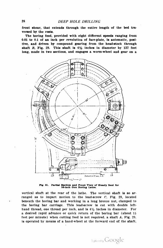
The steady rests have forged steel jaws, the inner ends of which
are provided with brass concave caps and openings for taking in
various sizes, which is accomplished by fitting into the steady rests
internal rings containing an extra set of long chuck jaws. The rests
consist of a housing in three parts, i. e., base, top, and chuck ring,
and are thus arranged to facilitate the removal of the work. They
are bolted to T-slots in the bed by large bolts, and are easily moved
in a longitudinal direction by hand, by applying a ratchet wrench at
the square end of a horizontal transverse shaft (shown in engraving
Fig. 31), journaled in the base of the rest. This shaft terminates in
a miter gear, engaging a similar gear in the upper end of a vertical
shaft, which in turn carries a pinion engaging a rack, secured to the
2S DEEP HOLE DRILLING
front shear, that extends through the entire length of the bed tra
versed by the rests.
The boring feed, provided with eight different speeds ranging from
0.01 to 0.1 of an inch per revolution of face-plate, is automatic, posi
tive, and driven by compound gearing from the head-stock through
shaft B, Fig. 29. This shaft is 4% inches in diameter by 137 feet
long, made in two sections, and engages a worm-wheel and gear on a
Pig. 31. Partial Section and Front View of Steady Rest for19-inch Gun Boring Lathe.
vertical shaft at the rear of the lathe. The vertical shaft is so ar
ranged as to impart motion to the lead-screw C, Fig. 29, located
beneath the boring bar and working in a long bronze nut, clamped to
the boring bar carriage. This lead-screw is cut with double left-
hand thread, one thread per inch, and is 4% inches in diameter. For
a desired rapid advance or quick return of the boring bar (about 15
feet per minute) when cutting feed is not required, a shaft A. Fig. 29.
is operated by means of a hand-wheel at the forward end of the shaft.
30 DEEP HOLE DRILLING
which is in communication with the friction clutches and pulleys
located in the rear of the lathe. The pulleys are driven by a separate
line shafting. The boring bar is of forged gun steel, 11 inches in
diameter, 61 feet 3% inches long, with a hole 4 inches diameter
throughout the whole length; its weight is equal to 6 tons. The head-
stock is 23 feet 4 inches long by 9 feet 10 inches wide, and is made in
one casting. The cone has five steps for a 10-inch belt and is strongly
back-geared, giving a wide range of changes of speed by means of
triple gearing to the faceplate.
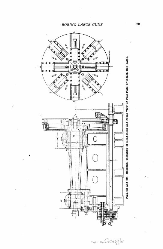
The main spindle is made of close-grained cast iron, 24 inches diam
eter at the main journal, and has a bearing in a cast-iron shell 31%
inches long. The rear bearing is similar in construction, but is only
16 inches diameter by 25% inches in length. The spindle is provided
with a flange to which the face-plate is bolted. It is also provided
with a thrust bearing of ample surface, with anti-friction washers
at the front bearing. The main spindle bearings are made in halves
and capped. The face-plate contains slots for clamping the work
and has several adjustable steel chuck jaws, shown in Fig. 33, which
have V-shaped faces. It also has a cast steel ring gear securely bolted
to it. This gear is 10% inches face, 8 feet 9%, inches outside diam
eter, by 3.59 inches circular pitch, and serves to drive the face-plate.
The face-plate weighs 13 tons.
All boring, reaming, turning and facing operations are performed
in the lathe described, the mechanism permitting of boring and turn
ing simultaneously, in order to facilitate rapid progress in construc
tion. The principal remaining operations for the completion of the
gun consist mainly in rifling the bore, and threading and slotting the
breech. The 16-inch breech-loading rifle boring and turning lathe
was designed by the ordnance department and manufactured by the
Pond Machine Tool Co., Plainfleld, N. J.
CHAPTER III.
CONSTRUCTION OP DEEP HOLE DRILLS.
It has always been an expensive operation to drill out the interior
of a hollow spindle. Indeed, it has not only been an expensive opera
tion, but, on account of the spindle being of high-carbon steel, it has
also been a difficult operation. Thus we find on the market hollow-
drawn tubing, such as the Shelby tubing, which is intended to be fur
nished at a less price than one can bore out the interior of a solid
bar. Of course, for some purposes this tubing answers very well.
But there are many cases, as in certain kinds of spindles, where such
tubing cannot be u^ed.
Nearly all lathes nowadays must be built with a hollow spindle.
This is also true of spindles of boring machines, drill presses, etc.,
and thus we have a large variety of work on machine tools which
involves deep drilling. The cost of deep drilling has been greatly
reduced recently, by several manufacturers, by means of what may
be termed a hollow drill. A strong flow of oil is forced through this
drill against the cut, and on its return carries the chips with it, thus
performing the double function of keeping the drill cool and clearing
out the chips.
A perspective view of one of these drills fitted up complete for
work, is indicated in Pig. 34. This drill was developed in the shops
of the Lodge & Shipley Machine Tool Co., Cincinnati, Ohio, by Mr.
N. D. Chard. The body of the drill B is made of machine steel. The
point P is made of tool steel, and is held in position by the taper pin T.
A hole H is drilled in the shank, and from this hole the oil is led to
slots S, which are milled along the outside. These slots run the full
length of the drill, and then shoot down at the ends, as indicated. F
is a flat spot for holding the drill.
A longitudinal sectional view of the drill is shown in Fig. 35, from
which the construction of the passageway for the oil is better seen.
H, again, is the oil inlet hole already referred to. Two small holes ,7
are . drilled into it in the manner indicated in this figure. The holes K
are then drilled, and a piece of brass tube is bent in the arc of a
circle and the ends are entered into the holes / and K. It is then
hammered down into place, and the joint is flushed with solder. The
slot P is milled out so as to have a semi-circular bottom. Into this
slot the cutter or point of the drill is neatly fitted. These points are
best made of Novo steel, as they then hold up better under high speed.
They are made as shown in Fig. 37. The hole H in the cutter is
reamed through the drill, while the cutter is clamped firmly back
against its seat at the end of the slot. The angle A is made about
20 degrees. The cutting edge is nicked at several places, as at N, in
order to break up the chips, this being done on the corner of an emery
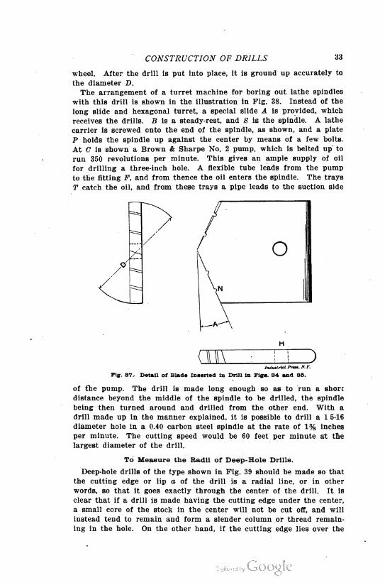
CONSTRUCTION OF DRILLS 33
wheel. After the drill is put into place, it is ground up accurately to
the diameter D.
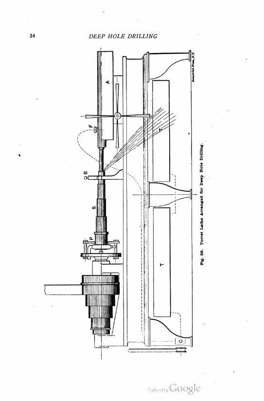
The arrangement of a turret machine for boring out lathe spindles
with this drill is shown in the illustration in Fig. 38. Instead of the
long slide and hexagonal turret, a special slide A is provided, which
receives the drills. B is a steady-rest, and 8 is the spindle. A lathe
carrier is screwed onto the end of the spindle, as shown, and a plate
P holds the spindle up against the center by means of a few holts.
At C is shown a Brown & Sharpe No. 2 pump, which is belted up to
run 350 revolutions per minute. This gives an ample supply of oil
for drilling a three-inch hole. A flexible tube leads from the pump
to the fitting F, and from thence the oil enters the spindle. The trays
T catch the oil, and from these trays a pipe leads to the suction side
CDIZZZLLDInduttrial Prtee. JV. K.
Fig. 37. Detail of Blade Inserted in Drill in Figs. 34 and 35.
of the pump. The drill is made long enough so as to run a short
distance beyond the middle of the spindle to be drilled, the spindle
being then turned around and drilled from the other end. With a
drill made up in the manner explained, it is possible to drill a 1 5-16
diameter hole in a 0.40 carbon steel spindle at the rate of 1% inches
per minute. The cutting speed would be 60 feet per minute at the
largest diameter of the drill.
To Measure the Radii of Deep-Hole Drills.
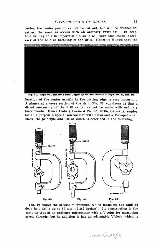
Deep-hole drills of the type shown in Fig. 39 should be made so that
the cutting edge or lip a of the drill is a radial line, or in other
words, so that it goes exactly through the center of the drill. It is
clear that if a drill is made having the cutting edge under the center,
a small core of the stock in the center will not be cut off, and will
instead tend to remain and form a slender column or thread remain
ing in the hole. On the other hand, if the cutting edge lies over the
CONSTRUCTION OF DRILLS 35
center, the center portion cannot be cut out, but will be crushed to
gether, the same as occurs with an ordinary twist drill. In deep-
hole drilling this is impermissible, as it will very soon cause inaccu
racy of the hole or breaking of the drill. Hence it follows that the
Fig. 39. Type of Deep Hole Drill Gaged by Method shown in Figs. 40, 41, and 42.
location of the center exactly in the cutting edge is very important.
A glance at a cross section of the drill, Fig. 39, convinces us that a
direct measuring of the drill center cannot be made with ordinary
instruments. Hence Ludwig Loewe & Co., of Berlin, Germany, employ
for this purpose a special micrometer with disks and a V-shaped anvil
block, the principle and use of which is described in the following.
Fig. 40. Pig. 41. Pig. 42.
Fig. 40 shows the special micrometer, which measures the radii cf
deep hole drills up to 60 mm. (2.362 inches). Its construction is the
same as that of an ordinary micrometer with a V-point for measuring
screw threads, but in addition it has an adjustable V-block which is
36 DEEP HOLE DRILLING
locked in position by a clamping screw; also, two disks 10 and 30 mm.
in diameter are provided. The smaller disk is used for setting the
micrometer for drills up to 32 mm., as shown in Fig. 40, and the
larger one for drills of 30 to 60 mm. diameter. For measuring drills
of small diameter up to 32 mm. the scale of the micrometer is set to
10.52 mm. (5 + 5 X 1.1045), and the disk of 10 mm. diameter is placed
in the V-block, after which the block with the disk is pushed against
the measuring point and clamped fast in this position, whereupon the
preliminary adjustment necessary is completed. For adjusting the
micrometer for drills of 30 to 60 mm. diameter, the 30 mm. disk is
used in the same manner, but the scale of the micrometer in this case
is adjusted to 16.56 mm. (15 X 1.1045). After having found the pre
liminary adjustment of the V-block for drills up to 32 mm. diameter,
Figs. 43 and 44. Micrometers for Measuring Radii of Deep Hole Drills.
as shown in Fig. 40, the radius or half the diameter of the drill to be
measured is multiplied by the constant 1.1045, and the scale of the
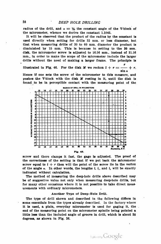
micrometer adjusted accordingly; or for greater convenience we may
use the diagram, Fig. 47, in which we can read off the product of
r X 1.1045 without calculation. For example, suppose we wish to
measure a drill whose radius is 7.45 mm. We must find the proper
reading for the micrometer screw when the drill is laid in the angle
block and the point adjusted, as indicated in Fig. 42. Turning to the
diagram, Fig. 47, we find in the upper horizontal scale the figure cor
responding to 7.45 and trace downward along the vertical line until
we reach the diagonal, thence going horizontally from this point to
ward the right or left, whichever may be convenient, we find in the
vertical scale the number 8.2 mm., or the product of 7.45 X 1.1045.
Hence, if in measuring the drill of 7.45 mm. radius, we get a microm
CONSTRUCTION OF DRILLS 37
eter reading of 8.2 mm., it is known that the apex of the angle of the
groove lies exactly in the center of the drill.
To adjust the micrometer for drills from 30 to 60 mm. diameter, the
radius of the drill is multiplied by the constant 1.1045, and 15 mm. is
subtracted from the product, or r X 1.1045 — 15 mm. = micrometer
setting. The diagram, Fig. 48, however, saves this calculation and is
Pig. 48. Fig. 46.
used in the same manner as Pig. 47. For example, to find the mi
crometer setting for a drill having a radius of 27.35 mm.: In the
upper horizontal scale we find the point corresponding to 27.35, and
follow the vertical line downward until it intersects the diagonal,
thence to the right or left to the vertical where we read 15.2. With
this datum, any excess or deficiency of thickness of the drill over the
RADIUS OF DRILL IN MILLIMETERS
8 ? 10 11
7
3S 9
S io;w■ ii
S 12
jjj 13
s »I IS
16
IT
18
\ S
_ 1
1
1 1 J 1 1 1
1
s
19 10 11 13 13 11 15 1G
Fig. 47.
center can 'be read off directly from the scale. Figs. 43 and 44 are
made from photographs showing substantially the same as Figs, 40, 41,
and 42.
Principle of the Gage.
The principle of the gage depends upon the proposition that the
homologous sides of similar triangles are in direct proportion. Hence
r r, r2
in Fig. 45 we have — = — = —, etc. Therefore the values of !; and
I h h
r
I, are easy to determine, since I — in which r corresponds to the
sin a
38 DEEP HOLE DRILLING
radius of the drill, and a — % the constant angle of the V-block of
the micrometer, whence we derive the constant 1.1045.
It will be observed that the product of the radius by the constant is
used directly when setting for drills 32 mm. or less diameter, but
that when measuring drills of 30 to 60 mm. diameter the product is
diminished by 15 mm. This is because in setting to the 30 mm.
disk, the micrometer screw is adjusted to 16.56 mm., instead of 31.56
mm., in order to make the scope of the micrometer include the larger
drills without the need of making a larger frame. The principle is
r
illustrated in Fig. 46. For the disk M we reckon I + r — h r.
sin a
Hence if one sets the screw of the micrometer to this measure, and
pushes the V-block with the disk M resting in it, until the disk is
found to be in perceptible contact with the measuring point of the
15 16 17 IS 19 20 2! 22 23 2 25 20 2? 28 29 3
Siv
16 17 18 19JU<wAiiMr»,JV.r.
Pig. 48.
screw and there clamps it fast, the gage is adjusted. The proof of
the correctness of the setting is that if we put back the micrometer
screw equal to I + r then will the point of the screw lie in the vertex
of the angle o. In other words, the lengths I, !„ and Z2 will be exactly
indicated without calculation.
The method of measuring the deep-hole drills above described may
be of suggestive value not only when measuring deep-hole drills, but
for many other occasions where it is not possible to take direct meas
urements with ordinary micrometers.
Another Type of Deep-Hole Drill.
The type of drill shown and described in the following differs in
some essentials from the types already described. In the factory where
it is used, a plain, everyday micrometer is used for gaging it, the
end of the measuring point on the micrometer spindle being pointed a
little less than the included angle of groove in drill, which is about 38
degrees, as shown in Fig. 36.
40 DEEP HOLE DRILLING
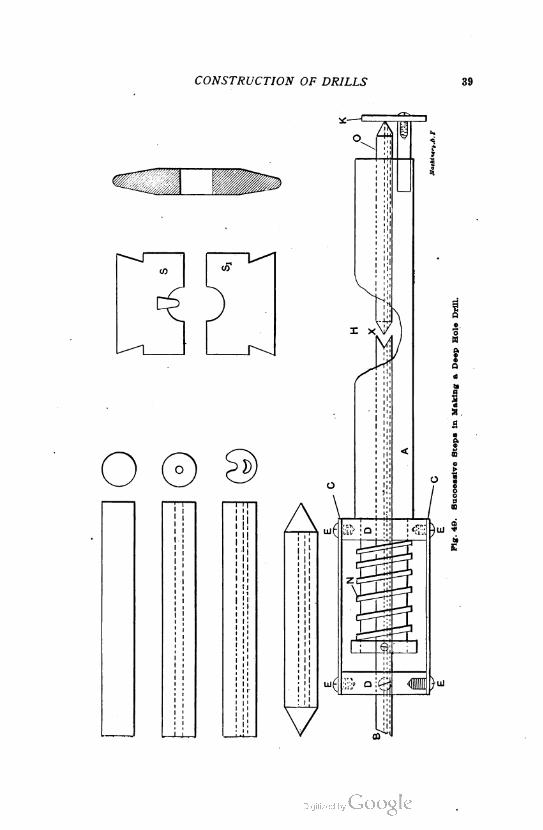
In making these drills, half-inch Novo stock is cut into lengths of
about 4 inches, Fig. 49; then a hole is drilled through the center;
next the piece is heated and struck up in dies 8 S„ which operation
forms a groove and forces the center hole below the center into a
crescent shape, as shown. It is then "pack annealed"; then both ends
are pointed to 60 degrees, and turned in a lathe on female centers to with
in 0.010 inch of finished size, this being allowed for grinding. After
being pointed, the work is held in a milling machine vise and the
groove is finished with the cutter shown in the upper right-hand corner
in Fig. 49. The groove is milled to a depth equal to one-half the fin
ished diameter, plus 0.005 inch, minus the amount to be ground out of
the groove, which varies according to the size of the drill and the
grade of steel used. In short, the bottom of the groove must be exactly
central when the drill is finished.
The drill is hardened two-thirds of its length, and the outside and
groove are ground. It is now placed in a brazing fixture, as shown in
the bottom view in Fig. 49. A is a, body of suitable length with a
hole drilled through it to accommodate all sizes of drills under
Pig. 60. Two Views of the Drill
inch. B is a steel tube a little under the size of the drill; a groove
is rolled the whole length of B to conform with the shape of the groove
in the drill. A V-groove is milled in the end of the tube to fit the
back end of the drill. Collars DD are bored out, one a loose fit on A,
the other on B.
The drill O is placed in the end of A, then B is inserted into the
other end of A. The two are brought together at the opening H, which
is milled out to allow point X to come in contact with the flame. A
small wooden plug is fitted into O and B to prevent the brazing stop
ping up the oil-hole. A small piece of silver solder is placed between
the two ends; then the swinging stop K is moved into place against
the end of drill O. Collars DD are held together by strips C and
screws E. Now B and O are brought together at X and are held
firmly in place by the stop K and tension of spring N, B being held
by D with the set-screw shown. With this rig, the brazing of the tube
and drill is satisfactorily accomplished, the device insuring correct
alignment.
This type of deep-hole drill is far superior to the old drill with
round oil hole, it being cheaper to make, at the same time as the
crescent-shaped hole allows a greater flow of oil at the cutting edge.