Joint Service Publication JSP 480 16 th Edition, Jan 2011 Superseding 15 th Edition Dated Dec 2009 And All Previous Editions DEFENCE CO-ORDINATING INSTALLATION DESIGN AUTHORITY MANUAL of REGULATIONS for INSTALLATION of COMMUNICATION & INFORMATION SYSTEMS
Transcript
Joint Service Publication JSP 480
16th Edition, Jan 2011 Superseding
15th Edition Dated Dec 2009 And All Previous Editions
U N C O N T R O L L E D C O P Y I F S A V E D O R P R I N T E D v i
PREFACE
1. The United Kingdom central government Cabinet Office has directed that all UK government departments implement practices and processes in accordance with the Information Assurance Governance Framework. The framework is owned by the Information Assurance Policy Committee (IAPC) and the Information Assurance Policy Programme Board (IAPPB).
2. The MOD has embraced the requirements of the Cabinet Office by the appointment of the Chief Information Officer (CIO) as the Senior Information Risk Owner (SIRO) for MOD CIS and by the publication of JSP 440, the MOD Security Manual. JSP 440 is published by the MOD Departmental Security Officer (DSO) and incorporates Cabinet Office governance and the requirements of HMG Security Policy Framework (SPF) as applicable to the MOD environment.
3. In compliance with the policies of the Cabinet Office, DSO and CIO, all MOD sites, and areas within other sites with systems storing, forwarding or processing MOD information are subject to Configuration Management (CM), and they must comply with the installation standards and procedures within this publication.
4. JSP 480 is owned by the Directorate of Business Resilience (DBR) and is published in order to:
a. Define the authority, responsibility and applicability of the Defence CIDA.
b. Publish the methodology used in discharging the duties associated with the role of CIDA in order to regulate the activities of those involved with MOD CIS engineering activities.
c. Identify the minimum CIDA installation standards and procedures that shall be applied to every CIS change within MOD Facilities.
5. Within this publication the following definitions apply:
a. Communication and Information Systems (CIS) is deemed to include all Command, Control, Communications, Computing and Intelligence (C4I), all Radar & Radio airfield navigation & information systems and all Communications-Electronics (C-E) equipment, peripherals and cabling, its location, infrastructure, environment and Radio Site Restriction zones.
b. Change is any new installation, erection, recovery, alteration, repositioning, Work Service, new build or demolition which affects any CIS hardware, cabling, location, infrastructure, environment or Radio Site Restriction zone. Change, in the context of this publication, does not refer to software revisions, or modification of CIS elements where size, weight, power consumption, heat dissipation, EMC, RADHAZ, EMPP, TEMPEST Health & Safety or installation standards are not affected.
c. MOD Facilities is to be interpreted as meaning all MOD and other locations or sites where MOD equipment is installed or data processed.
6. In addition to the generic requirements of this publication, certain locations have site specific, CIDA approved, installation standards and procedures to cater for local or manufacturers’ requirements. Where there is conflict between this publication and a site specific requirement, the more rigorous is to be followed. In cases of disagreement, lack of clarity or interpretation, Defence CIDA will investigate and determine the requirement to be followed. A listing of those locations with specific requirements may be viewed on the CIDA
JSP 480 16th Edition Jan 11
U N C O N T R O L L E D C O P Y I F S A V E D O R P R I N T E D v i i
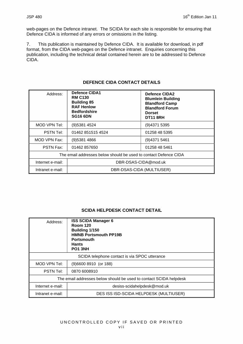
web-pages on the Defence intranet. The SCIDA for each site is responsible for ensuring that Defence CIDA is informed of any errors or omissions in the listing.
7. This publication is maintained by Defence CIDA. It is available for download, in pdf format, from the CIDA web-pages on the Defence intranet. Enquiries concerning this publication, including the technical detail contained herein are to be addressed to Defence CIDA.
Intranet e-mail: DES ISS ISD-SCIDA HELPDESK (MULTIUSER)
JSP 480 16th Edition Jan 11
U N C O N T R O L L E D C O P Y I F S A V E D O R P R I N T E D v i i i
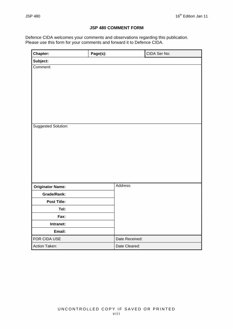
JSP 480 COMMENT FORM
Defence CIDA welcomes your comments and observations regarding this publication. Please use this form for your comments and forward it to Defence CIDA.
Chapter: Page(s): CIDA Ser No:
Subject: Comment:
Suggested Solution:
Originator Name:
Grade/Rank:
Post Title:
Tel:
Fax:
Intranet:
Email:
Address:
FOR CIDA USE Date Received:
Action Taken: Date Cleared:
JSP 480 16th Edition Jan 11
U N C O N T R O L L E D C O P Y I F S A V E D O R P R I N T E D i x
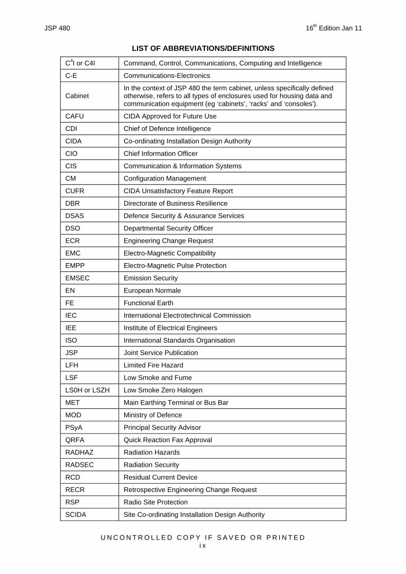
LIST OF ABBREVIATIONS/DEFINITIONS
C4I or C4I Command, Control, Communications, Computing and Intelligence
C-E Communications-Electronics
Cabinet In the context of JSP 480 the term cabinet, unless specifically defined otherwise, refers to all types of enclosures used for housing data and communication equipment (eg ‘cabinets’, ‘racks’ and ‘consoles’).
CAFU CIDA Approved for Future Use
CDI Chief of Defence Intelligence
CIDA Co-ordinating Installation Design Authority
CIO Chief Information Officer
CIS Communication & Information Systems
CM Configuration Management
CUFR CIDA Unsatisfactory Feature Report
DBR Directorate of Business Resilience
DSAS Defence Security & Assurance Services
DSO Departmental Security Officer
ECR Engineering Change Request
EMC Electro-Magnetic Compatibility
EMPP Electro-Magnetic Pulse Protection
EMSEC Emission Security
EN European Normale
FE Functional Earth
IEC International Electrotechnical Commission
IEE Institute of Electrical Engineers
ISO International Standards Organisation
JSP Joint Service Publication
LFH Limited Fire Hazard
LSF Low Smoke and Fume
LS0H or LSZH Low Smoke Zero Halogen
MET Main Earthing Terminal or Bus Bar
MOD Ministry of Defence
PSyA Principal Security Advisor
QRFA Quick Reaction Fax Approval
RADHAZ Radiation Hazards
RADSEC Radiation Security
RCD Residual Current Device
RECR Retrospective Engineering Change Request
RSP Radio Site Protection
SCIDA Site Co-ordinating Installation Design Authority
JSP 480 16th Edition Jan 11
U N C O N T R O L L E D C O P Y I F S A V E D O R P R I N T E D x
SDIP SECAN Doctrine and Information Publication
SIRO Senior Information Risk Owner
SPF Security Policy Framework
TCO or TCCO TEMPEST Control Officer or TEMPEST Configuration Control Officer
TEMPEST The phenomenon and investigation of compromising emanations
BS EN ISO 9431:1999 Construction drawings ~ Spaces for drawing and for text, and title blocks on drawing sheets 12
BS ISO 10007:2003 Quality Management Systems ~ Guidelines For Configuration Management 02 04
JSP 480 16th Edition Jan 11
U N C O N T R O L L E D C O P Y I F S A V E D O R P R I N T E D x i i
BS EN 12825:2001 Raised access floors 06
BS EN 13101:2002 Steps for underground man entry chambers ~ Requirements, marking, testing and evaluation of conformity 11
BS ISO/IEC 27002:2005 Information technology - Security techniques - Code of practice for information security management 01
BS EN 50173-x:2007 Information technology ~ Generic cabling systems (Parts 1, 2 and 5) 08
BS EN 50174-x:2009/2003 Information technology ~ Cabling installation (Parts 1, 2 and 3) 06 08
10 11
BS EN 60297-3-100:2009
Mechanical structures for electronic equipment Dimensions of mechanical structures of the 482,6 mm (19 in) series Part 3-100: Basic dimensions of front panels, subracks, chassis, racks and cabinets
06
BS EN 60529:1992 Degree of protection provided by enclosures (IP code) 06
BS EN 60950-1:2006 + A1:2010 Information technology equipment-Safety ~ General requirements 06
BS EN 62040-1:2008 Uninterruptible power systems (UPS) ~ General and safety requirements for UPS 07
BS EN 62305-3:2006 Protection against Lightning 07
BS IEC 61000-5-2:1997 Earthing and cabling 07
BS EN 50267-2-2:1999 Common test methods for cables under fire conditions – Tests on gases evolved during combustion of materials from cables (Part 2-2)
05
JSP 480 16th Edition Jan 11
U N C O N T R O L L E D C O P Y I F S A V E D O R P R I N T E D x i i i
REFERENCED PUBLICATIONS
Joint Service Publications Chapters
JSP 375
Volume 2, Leaflet 07
Volume 2, Leaflet 10
Volume 2, Leaflet 12
Volume 2, Leaflet 33
MOD Health & Safety Handbook
Working at Heights
Work in Confined Spaces
Safety When Working With Electricity And Electrical Equipment
Safety in Excavation
11
11
06 07
11
JSP 440
Part 8, Sect 1, Chapter 2
Part 8, Sect 2, Chapter 1
Part 8, Sect 5, Chapter 6
Part 8, Sect 5, Chapter 9
Part 9, Chapter 4
The Defence Manual of Security
Introduction to CIS Security, Risk Analysis and Risk Management
Accreditation of CIS, Accreditation Responsibilities
Communications Security, Security in Wide Area (bearer) Networks
Compliance & Assurance, Validation, Verification and Oversight
Preface04 06
02
12
01
08 1011 12
02
JSP 602:1034 Network Mapping and Configuration Management 01
JSP 846 MOD Radio Site Clearance and Protection ~ UK 04
NATO Publications Chapters
SDIP 29 Facility Design Criteria and Installation of Equipment for the Processing of Classified Information
04 06 08
10 11
UK Statutory Instruments Chapters
SI 1989 No 635 Health And Safety ~ The Electricity at Work Regulations 1989 06 07
SI 1996 No 341 Health And Safety (Safety Signs and Signals) Regulations 1996 07
SI 1998 No 2306 Health And Safety ~ The Provision and Use of Work Equipment Regulations 1998 06 07
SI 2005 No 1541 Regulatory Reform, England And Wales - The Regulatory Reform (Fire Safety) Order 2005 05
Miscellaneous Publications Chapters
The PACE Crown Fire Standards 05
Cabinet Office ~ Central Sponsor for Information Assurance ~ Information Assurance Governance Framework
Preface01
Cabinet Office ~ Her Majesty’s Government ~ Security Policy Framework Preface01
JSP 480 16th Edition Jan 11
U N C O N T R O L L E D C O P Y I F S A V E D O R P R I N T E D x i v
UPDATED CONTENT These pages give a summary of content that has been amended from that published in the previous edition. It should be noted that some of these changes constitute a revision of CIDA policy.
General. Publication changed to bring it in line with JSP 101 (Defence Writing) standard. Minor editorial corrections have been made throughout the publication.
Preface. SCIDA contact details updated.
Chapter 02, Configuration Management and the CIDA Role. Tables 1 and 2 at Annex A to Chapter 02 have been revised to reflect the reduced requirements for CM of Service Level 3 facilities.
Chapter 04, The CIDA Engineering Change Process. Paragraph 0414 has been amended to reflect that only AutoCAD compatible media is the requirement for ‘As Fitted’ drawings. Paragraph 0421 has been amended allowing, under certain circumstances, minor non-conformances to be accepted by the Authority.
Chapter 05, Limited Fire Hazard Cables & Materials. BS EN 50267-2-2 has been included in Table 5-1 with reference to Halogen content. Paragraph 0505 has been reworked to improve readability.
Chapter 06, The CIS Physical Environment. Paragraph 0605 has been reworked to clarify the required connections to the Main Earth Terminal (MET). Cabinet height in paragraph 0612a has been changed from 45U to 42U. Paragraph 0612e has been amended to clarify the requirement for cabinet labelling. Paragraph 0616 has been updated to discuss the use of cabinets on false floors and proprietary fixing systems.
Chapter 07, The CIS Electrical Environment. Paragraph 0706 has been amended to clarify the requirement for bonding parts of cabinets. A new sub section has been introduced discussing Functional Earthing of Cabinets. A new sub section has been introduced outlining the requirements for lightning protection of external pathways. The sections on isolation, switching and emergency switching have been reworked to clarify the requirements. The section on extension leads has been amended to exclude the use of multi-way adaptor plug blocks.
Chapter 08, Structured Cabling Systems. A new paragraph has been included to reflect the maximum length of a work area cord.
Chapter 9, Cable Identification. Chapter has been reworked to provide a better layout.
Chapter 11, CIS Outside Plant. Chapter has been revised to allow, in certain cases, directly buried cables. Paragraph 1122 and Fig 11-1 have been amended reducing the separation between ducts as they enter pits.
JSP 480 16th Edition Jan 11
U N C O N T R O L L E D C O P Y I F S A V E D O R P R I N T E D 0 1 - 1
CHAPTER 01
RESPONSIBILITIES AND DEFINITIONS OF CIDA AND ASSOCIATED ROLES
INTRODUCTION
0101. In compliance with legal requirements, the HMG Security Policy Framework and the Cabinet Office Information Assurance Governance Framework, CIO, through D CBM J6 Executive Group, established the MOD CIS Resilience Policy and Recovery Strategy and the DSO publishes JSP 440, the MOD Security Manual. These MOD policy documents mandate CIS security, resilience, change management, configuration control, installation design control and accreditation processes, thus directly delivering the Cabinet Office governance requirement for compliance with ISO 17799 (BS ISO/IEC 27002), the provision of an Accreditation process and the use of ITIL best practice.
CO-ORDINATING INSTALLATION DESIGN AUTHORITY
0102. The Defence Co-ordinating Installation Design Authority (CIDA) is a team within the Defence Security & Assurance Services (DSAS) branch of the MOD Business Resilience Directorate (DBR), authorised by:
a. DSO through JSP 440 ‘The Defence Manual of Security’ which cites CIDA as the technical agent of the DSAS and TLB Principal Security Advisers (PSyA) to assist in the security accreditation process of all CIS installed at all MOD, List X and identifiable ‘service delivery’ locations. DSO has mandated that the CIDA role is a core function and must be performed by a member of MOD staff.
b. CIO, through JSP 602:1034 ~ ‘Network Mapping and Configuration Management’, which cites CIDA as the agency mandated with ensuring that the optimum operational availability, security and integrity of system infrastructure is maintained through sensible application of standards and change management.
c. CIO and D CBM J6 Executive Group who jointly direct that a security, resilience and Configuration Management (CM) discipline is to be applied to all CIS for which they have responsibility. They further direct that the governance and assurance of the physical and environmental aspects of CIS CM and installation design are to be discharged by CIDA.
0103. Through this authority the CIDA has control over the installation design, site configuration and environment such that Availability, Flexibility, Economy, Confidentiality, Integrity and Resilience may be maintained, whilst assuring that within a defined site, all security and safety requirements relating to each CIS installation are met and maintained.
a. Availability. Optimising operational availability by ensuring that installations are implemented in accordance with relevant standards and good engineering practice, and maintained under effective configuration management. The aim is to reduce system failure due to poor installation standards and facilitate maintainability, fault rectification and future engineering change.
b. Flexibility. By ensuring that correct installation documentation and standards are maintained, that installations and recoveries are conducted in a manner that facilitates future change and that a complete Facility information set is available to future Change Designers.
c. Economy. By ensuring that spare capacity is correctly utilised, that additional systems are installed in a manner that makes best use of the site’s infrastructure and
JSP 480 16th Edition Jan 11
U N C O N T R O L L E D C O P Y I F S A V E D O R P R I N T E D 0 1 - 2
available space and to co-ordinate change to avoid conflict or promote efficiency such as through combined cross-site duct projects or common works service provision.
d. Confidentiality. By ensuring that where appropriate, installations meet the requirements for RADSEC and are maintained under configuration control.
e. Integrity. By ensuring that installations will not suffer from or be the cause of electrical interference to other co-located installations (EMC).
f. Resilience. By ensuring that where appropriate, installations are provided with diversity of location, power, connectivity and cooling to facilitate continuity of service during unforeseen disruptive malfunction.
0104. Defence CIDA is responsible for ensuring that the physical and environmental aspects of Defence CIS installations are compliant with the Cabinet Office Information Assurance Governance Framework and HMG Security Policy Framework. To ensure compliance with these policies:
a. CIDA Certification of new and extant CIS installations is required before CIS systems can be accredited and re-accredited.
b. SCIDAs shall be established and maintained for every CIS facility. Defence CIDA’s SCIDA Framework Document is the minimum delivery requirement for SCIDAs to provide the necessary Configuration Management of the physical and environmental aspects of Defence CIS Installations.
0105. In accordance with HMG Security Policy Framework, CIDA utilises a management approach to risk. Risk is assessed to identify the potential impact to MOD business through the loss or reduction of Confidentiality, Integrity, Availability or Resilience from the viewpoint of the physical and environmental aspects of CIS installations.
0106. Assessment of the risk picture is facilitated by CIDA activities as follows:
a. Questionnaire, health-check and audit of SCIDA.
b. System survey and system health-check.
c. DSAS tasked ‘List X’ company assessment.
d. Site survey.
e. Assessment of SCIDA generated report.
0107. Identified risk is managed through normal CIDA process (see Chapter 04) or one of the following routes:
a. The problem is rectified to remove the risk.
b. Risk to MOD data is directed to the appropriate system accreditor for resolution or escalation, as appropriate; or for formal acceptance by the appropriate Information Risk Officer.
c. Risk to personnel or facilities is directed through the facility management to the Head of Establishment for resolution or acceptance.
JSP 480 16th Edition Jan 11
U N C O N T R O L L E D C O P Y I F S A V E D O R P R I N T E D 0 1 - 3
SITE CO-ORDINATING INSTALLATION DESIGN AUTHORITY
0108. A Site Co-ordinating Installation Design Authority (SCIDA) will normally be appointed or contracted to undertake some or all delegateable CIDA duties with respect to a site or group of sites. In every SCIDA appointment, the Defence CIDA shall provide detailed requirements in a formal Site Specific SCIDA Agreement, or Contract Conditions.
0109. From the viewpoint of co-ordination of change and the regulation of installation standards, a SCIDA should preferably be independent from the organisations who deliver change.
0110. The SCIDA derives its authority from CIDA and is responsible to CIDA for the delivery of the delegated role. The SCIDA function is to ensure that the full benefits of Physical and Environmental CM for MOD CIS are delivered across facilities documented in the SCIDA Agreement or Contract. The effectiveness of a SCIDA shall be evaluated, by Defence CIDA personnel, through formal audit of both the SCIDA and the SCIDA process.
0111. In certain circumstances, CIDA will authorise the appointment of a Technical Supervisory Co-ordinating Installation Design Authority (TSCIDA) to supervise the SCIDA(s) in the day to day running of the SCIDA role. The TSCIDA will always be a MOD employee with a technical communications background, and may be part of another, relevant, MOD organisation. The TSCIDA will always report to the CIDA on aspects relating to their TSCIDA role.
0112. To avoid lengthening chains of responsibility, the appointment of a TSCIDA should be limited to essential situations. A TSCIDA should not be appointed over a SCIDA where an individual is primarily filling the ‘Contract Manager’ as opposed to a supervisor role.
0113. A TSCIDA may be appointed under the following circumstances:
a. Where a non MOD SCIDA has been appointed or contracted and the Defence CIDA is unable to provide the technical support required at a specific location; or
b. To co-ordinate or provide a technical focal point for specialist areas, normally, across several sites.
SYSTEM DESIGN AUTHORITY
0114. A System Design Authority (SDA), in co-operation with the SCIDA, is responsible for ensuring that the system design meets the agreed specification or requirement, in terms of functionality, performance, capacity, security, safety and ergonomics. The responsibilities of an SDA include, but are not necessarily limited to, the following:
a. Defining the environmental conditions in which the system will be required to operate, including all lighting, ventilation and power requirements.
b. The production and submission of the master system design drawings and other relevant documentation to the Installation Design Authority and where appropriate, to the configuration control authority.
c. The identification and specification of the spares required for testing, commissioning and ongoing support.
d. The preparation and issuing of test plans and procedures and providing supervision during commissioning.
JSP 480 16th Edition Jan 11
U N C O N T R O L L E D C O P Y I F S A V E D O R P R I N T E D 0 1 - 4
e. The design of system modifications and the issue of modification details in the form of drawings or instructions.
INSTALLATION DESIGN AUTHORITY
0115. An Installation Design Authority (IDA) is responsible for ensuring that a System Design is developed into a functional Installation Design that complies with SCIDA requirements. The design will always require SCIDA endorsement prior to the change taking place unless a specific formal agreement is in place with the Defence CIDA to cover operational requirements. The responsibilities of an IDA include the use of the full CIDA Engineering Change Request (ECR) process and include, but are not necessarily limited to the following:
a. Using an agreed ECR (Part 1) process to provide the earliest possible notification to SCIDA of a proposition for change.
b. Obtaining SCIDA drawings, where they exist, to obviate duplication of effort.
c. Obtaining information from SCIDA concerning other concurrent change, generic and site specific installation requirements and known spare capacity at the site.
d. Defining the physical layout of the system, taking into account all SCIDA requirements, safety and ergonomic aspects.
e. Ensuring that the design of an installation satisfies all TEMPEST, EMP, EMC, RADHAZ and Health & Safety requirements.
f. Obtaining agreement on the demarcation between Works Infrastructures and CIS installation.
g. Identifying, specifying, preparing and submitting any Works Services elements including the requirements for power outlets, lighting, air conditioning, physical security measures and making good. Works Services proposals must be approved by the SCIDA before their submission to the Works Representative.
h. Identifying and specifying the requirement for communications links, equipment cabinets, desks and associated furniture.
i. The preparation of installation documentation in the form of drawings, specifications and instructions, including the design of any required modifications to existing installations.
j. Obtaining approval for the Change, by the timely submission of (ECR Part 2) proposals to the SCIDA and, where appropriate, receipt of SCIDA endorsement (ECR Part 3).
k. Specifying the necessary tests, test equipment and testing procedures for the CIS installation.
l. The identification and removal of any and all equipment, racks, containment, fixings and cabling which has been rendered redundant by the installation of the new system.
m. Co-ordinating the opportunity for SCIDA assessment of the completed Change before the Change Implementer leaves site. (ECR Part 4).
n. The provision of ‘As Fitted’ drawings and information to SCIDA to allow update of the SCIDA information set.
JSP 480 16th Edition Jan 11
U N C O N T R O L L E D C O P Y I F S A V E D O R P R I N T E D 0 1 - 5
o. Obtain confirmation that the Change meets all SCIDA requirements prior to the task being considered complete. (SCIDA issues ECR Part 5).
TEMPEST CONTROL OFFICER
0116. For deployments away from CIDA planned or managed sites, the UK commander of the deployment is responsible for configuration control of CIS containing UK national information. This configuration control is to be effected by a TEMPEST Control Officer acting with the authority of the commander. The requirement for a TCO will normally be superseded by the appointment of a SCIDA.
0117. The TCO is responsible for ensuring that all CIS facilities processing data protectively marked CONFIDENTIAL and above are correctly installed. He is to ensure that only authorised changes are made to CIS facilities that are subject to TEMPEST Control or countermeasures and is to devise, implement and maintain a TEMPEST Control Plan (TCP).
0118. Enforcement of installation standards and TEMPEST countermeasures on operations requires personnel with the appropriate engineering skills, authority, responsibility and training. The TCO role is complimentary to the Information Technology Security Officer (ITSO) role and both are required to gain accreditation. Full details of the TCO role, including exemplar Terms Of Reference (TOR) are at:
a. JSP 440 ‘The Defence Manual of Security’ Part 8 ‘Communication And Information Systems’
U N C O N T R O L L E D C O P Y I F S A V E D O R P R I N T E D 0 2 - 1
CHAPTER 02
CONFIGURATION MANAGEMENT & THE CIDA ROLE
INTRODUCTION
0201. International Standard BS ISO 10007:2003 ‘Quality Management Systems ~ Guidelines For Configuration Management’ provides guidelines for Configuration Management (CM), and defines it as a management discipline that applies technical and administrative direction to the development, production and support life-cycle of a configuration item. The discipline is applicable to hardware, infrastructure, software, processed materials, services and related technical documentation. CM is an integral part of life-cycle management, and is applicable to the support of projects from concept through to design, development, procurement, production, installation, operation and maintenance and to the disposal of products.
0202. The main objective of CM is to document and provide full visibility of the product’s present configuration and on the status of achievement of its physical and functional requirements. A further objective is that everyone working on the project at any time in its life-cycle uses correct and accurate documentation.
0203. It is essential that the technical and organisational activities which are performed within the CM process are fully integrated for the process to be effective. These activities are listed below:
a. Configuration identification.
b. Configuration control.
c. Configuration status accounting.
d. Configuration audit.
CIDA APPLICATION OF CONFIGURATION MANAGEMENT
0204. Defence CIDA is mandated with the responsibility for optimising the maintenance of operational capability, flight safety and electrical security by co-ordinating changes into MOD CIS facilities and by regulating installation standards. CIDA authority applies to all sites, buildings, rooms and mobile/transportable equipment facilities but not to aircraft, ships or submarines.
0205. Day to day activities on a site are normally delegated to the Site CIDA (SCIDA) except for deployed operations which are usually managed centrally. The application of CM to a MOD CIS facility is dependent upon the CIDA Service Level assigned to that facility (see guidelines at Annex A to this Chapter for details). In accordance with the mandates of JSP 440, the minimum requirement, is the granting of Installation Approval by CIDA.
0206. CIDA has no remit to include system or application software in its CM activities. The CIDA CM ‘product’, therefore, is the physical, in terms of layout, and electrical, in terms of connectivity, facets of all MOD CIS facilities. CIDA discharges its CM responsibilities for MOD CIS facilities by ensuring that the following procedures are adhered to.
Configuration Identification
0207. A library of ‘As Fitted’ drawings, including Site Plans, Location Maps and system documentation is generated from site survey and/or assembled from extant information to form
JSP 480 16th Edition Jan 11
U N C O N T R O L L E D C O P Y I F S A V E D O R P R I N T E D 0 2 - 2
the configuration control baseline for all MOD CIS. Drawing content and standards are fully documented at Chapter 12.
Configuration Control
0208. All changes to a CIDA controlled facility must go through a Change Control procedure to obtain CIDA endorsement before the change is implemented. An example of an acceptable CIDA ‘change control process’ is documented at Chapter 04.
Configuration Status Accounting
0209. To facilitate visibility, traceability and the efficient management of evolving configuration, CIDA or SCIDA maintain records of pertinent data relative to all ‘change’ to all CIS facilities that fall within their area of responsibility, and may use a variety of resources, in either paper or digital format, dependent on the volume of data that is recorded.
Configuration Audit
0210. To ensure continuing conformance to CIDA requirements, sites must be regularly inspected by the SCIDA. This will be carried out to an agreed ‘SCIDA Inspection Plan’, with associated Inspection Reports produced. Separately, Defence CIDA conducts an assurance regime for all SCIDA/sites, the timing of which being determined by the Defence CIDA in consultation with the SCIDA. In combination, the CIDA and SCIDA process constitutes the Configuration Audit.
0211. The frequency of Configuration Audits of MOD CIS facilities depends on the ‘CIDA Service Level’ for the facility (in accordance with the guidelines at Annex A) and the Criticality Level (CL), or Asset Value, of the individual CIS.
0212. The CL is a reflection of the asset valuation based on the importance of the CIS to both the facility mission, and for Defence as a whole. It is assigned to a system by the ‘Data Owner’ or ‘System Operating Authority’ and is recorded in the Security Policy Documentation for the CIS concerned. The four defined CL are described at:
a. JSP 440 ‘The Defence Manual of Security’ Part 8 ‘Communication and Information Systems’
Section 1 ‘Introduction to CIS Security’ Chapter 2 ‘Risk Analysis and Risk Management’
Annex A ‘CIS Criticality Levels’.
0213. The configuration audit examines the ‘As Fitted’ product to its configuration documentation to ensure compliance. The audit confirms that the product conforms to the physical and functional requirements through assessment of:
a. The comprehensiveness of the CIDA baseline package.
b. Installation standards and maintainability across the whole facility meet CIDA requirements.
c. Common Equipment layout and engineering requirements are being maintained.
d. Information Security requirements of JSP 440 continue to be maintained.
e. The progress of observations and actions raised in previous audit reports.
f. The local procedures intended to prevent unauthorised change.
JSP 480 16th Edition Jan 11
U N C O N T R O L L E D C O P Y I F S A V E D O R P R I N T E D 0 2 - 3
g. Unauthorised changes that have occurred and where relevant, the organisation responsible.
0214. On completion of a configuration audit, a report of the results, including recommended actions to correct non compliance, will be issued to all ‘interested parties’.
0215. Where sub-standard work is identified, or where an unauthorised change adversely affects a CIDA approved change or CIDA’s overall plan for the facility, the cost of resolving the problem must be met by the organisation responsible for raising the contract or work instruction that resulted in the unauthorised or sub-standard work. The responsibility for meeting these costs may be transferred to the organisation responsible for delivering the change, if this is indicated in the associated tasking documentation.
JSP 480 16th Edition Jan 11
U N C O N T R O L L E D C O P Y I F S A V E D O R P R I N T E D 0 2 - A - 1
ANNEX A TO CHAPTER 02
CIDA SERVICE LEVELS
1. Configuration Management (CM) requires resources and thus must be directed where the gain is most tangible. The CIDA Service Levels for MOD facilities are designed to ensure that areas with the highest business importance are afforded the most significant protection. This gives the greatest benefit to operational capability, safety and security. Their application also helps to identify those sites that require CM but where it is not currently being delivered, thereby increasing the understanding of existing and future resource requirements.
2. In recognition of the above, 3 levels of provision have been devised to reflect the degree of effort required to comply with the requirements. Service Levels are assigned through consultation between CIDA, TSCIDA where appropriate, the facility stakeholders and the SCIDA. The facility stakeholders may include, but not necessarily be limited to, the Engineering and Operational Sponsors, TEMPEST Control Officer (TCO), Information Technology Security Officer (ITSO) and Local Engineering Staff. Once assigned, a Service Level may be reassigned by agreement of all relevant agencies. A site may contain separate areas assigned differing service levels.
3. The SCIDA Inspection regime is directly related to the assigned CIDA Service Levels. It also takes into account the guidance within JSP 440, Part 9, Chapter 4, with regard to the frequency of CIDA Conformance Reviews.
4. The Defence CIDA Service Levels are defined as follows:
a. CIDA SERVICE LEVEL 1
(1) MOD facilities directly supporting Operational Capability, OR
(2) Facilities where short term or extended denial of service would cause significant disruption to operational or direct operational support capability, OR
(3) Facilities having a high population of data processing equipment accredited at CONFIDENTIAL or higher, OR
(4) Flight Safety related facilities.
b. CIDA SERVICE LEVEL 2
(1) Facilities not directly supporting Operational Capability AND having a low population of equipment accredited at CONFIDENTIAL or higher, OR
(2) Facilities not directly supporting Operational Capability AND having a high population of equipment accredited at RESTRICTED or lower.
c. CIDA SERVICE LEVEL 3
(1) Facilities not directly supporting Operational Capability AND having a low population of equipment accredited at RESTRICTED or lower.
5. MOD facilities that only contain telephones, accredited at RESTRICTED or below, or internet installations are not necessarily subject to CM. However, all wireless installations are to be the subject of SCIDA control.
6. All cross site ducting and cables are to be subject to CM and will be treated as Service Level 2 as a minimum.
JSP 480 16th Edition Jan 11
U N C O N T R O L L E D C O P Y I F S A V E D O R P R I N T E D 0 2 - A - 2
7. Notwithstanding the CM requirements of CIDA, the full Radio Site Protection (RSP) procedures are to be followed where applicable.
8. Table 2-1 is an overview of the minimum CM requirements at facilities with different service levels. Table 2-2 is an alternative way of viewing the minimum CM requirements.
Table 2-1 Service Levels, Depth of CM and Frequency of Inspection
Service Level
Extent of Configuration
Control
Minimum Frequency of FacilityInspections by SCIDA
Requirement for CM Drawings
1 Establish/maintain Configuration
Control Baseline
Full ECR process mandatory 1 yearly Full SCIDA drawing set
established and maintained
2 Full ECR process mandatory
Note 1 2 yearly
Full TEMPEST drawing set established and maintained
IDA As Fitted drawings held, alternatively, SCIDA drawings
3
All changes must be assessedECR Pt 1 Mandatory
Pts 2-5 determined by SCIDA
Notes 2 and 3
On request from site IDA ‘As Fitted’ drawings may
be held, SCIDA drawings optional
Notes:
1. For traditional telephone extensions (Plain Old Telephone Service [POTS]): All changes must be assessed. ECR Pt 1 Mandatory. Pts 2-5 at SCIDA discretion (ECR 2-5 mandatory for facilities containing CIS at CONFIDENTIAL or higher).
2. For traditional telephone extensions (POTS): ECR Pts 1-5 at SCIDA discretion. The ATO is to ensure full liaison with the SCIDA to identify Facility Service Levels.
3. Decision not to proceed to ECR Pt 5 will require a form of written design endorsement to the Design Agency and written installation conformance to the Security Accreditor (SCIDA shall respond to an ECR Pt 1 within 10 working days. Where a response is not received within 15 working days, the IDA may proceed but installations must be JSP 480 compliant and may be subject to inspection. In instances where work was undertaken without ECR Pt 1 confirmation, the IDA must inform SCIDA of the completion date, within 15 working days, and confirm its conformance to JSP 480). If the proposed change will raise the Service Level of a facility or is within the sphere of influence of a facility at Service Level 1 or 2, then approval to proceed must be obtained from SCIDA.
JSP 480 16th Edition Jan 11
U N C O N T R O L L E D C O P Y I F S A V E D O R P R I N T E D 0 2 - A - 3
Table 2-2 Minimum SCIDA CM Requirement
Item Activity Service level 1 Service level 2 Service level 3
1 SCIDA Advice
2 Change Control Process Note 1
3 Maintain Drawings & Information Note 2 Note 3
4 Conduct SCIDA Inspections Note 4 Note 5 Note 6
5 Establish the
Facility’s Configuration
Control Baseline
Notes:
1. Notification of all Change (ECR Pt 1 or equivalent) is mandatory. The need for ECR Pts 2 – 5 will be determined by SCIDA. Decisions not to proceed to ECR Part 5 will require a form of written design endorsement to the Design Agency and written installation conformance to the Security Accreditor. (SCIDA shall respond to an ECR Pt 1 within 10 working days. Where a response is not received within 15 working days, the IDA may proceed but installations must be JSP 480 compliant and may be subject to inspection. In instances where work was undertaken without ECR Pt 1 confirmation, the IDA must inform SCIDA of the completion date, within 15 working days, and confirm its conformance to JSP 480). If the proposed change will raise the Service Level of a facility or is within the sphere of influence of a facility at Service Level 1 or 2, then approval to proceed must be obtained from SCIDA.
2. Create & maintain TEMPEST drawings for all CIS facilities processing information at CONFIDENTIAL or higher. IDA ‘As Fitted’ Drawings, or alternatively SCIDA Drawings, are to be held.
3. IDA ‘As Fitted’ Drawings may be held.
4. Mandatory yearly Inspection of all CIS facilities by SCIDA.
5. Mandatory 2 yearly inspection of all CIS facilities by SCIDA.
6. Inspections by SCIDA on request from site.
JSP 480 16th Edition Jan 11
U N C O N T R O L L E D C O P Y I F S A V E D O R P R I N T E D 0 3 - 1
CHAPTER 03
DIVISION OF RESPONSIBILITIES
0301. The Defence CIDA organisation, based at RAF Henlow and Blandford Camp, provides CIDA cover, primarily on a geographic basis, with specific responsibilities as follows:
a. CIDA 1, RAF Henlow. North East UK, Middle East, Gibraltar, NATO sites, Italy, Benelux, Iberia, Greece, France, Scandinavia, Africa, N & S America and OOA sites.
b. CIDA 2, Blandford Camp. South West UK, Northern Ireland, Germany, Balkans, Cyprus, Falkland Islands, Ascension Island, Australia, Central and Eastern Asia/Pacific and OOA sites.
0302. Detailed information on the CIDA section, SCIDA and TSCIDA (if appropriate) with responsibility for a particular facility is held on a listing which may be viewed on the CIDA web-pages on the Defence intranet.
0303. Errors, omissions or queries relating to specific content of the listing or requests for information from those sites that do not have Defence intranet access can be resolved by contact with Defence CIDA.
JSP 480 16th Edition Jan 11
U N C O N T R O L L E D C O P Y I F S A V E D O R P R I N T E D 0 4 - 1
CHAPTER 04
THE CIDA ENGINEERING CHANGE PROCESS
INTRODUCTION
0401. A change may be initiated from within a facility, by an IPT, a customer, contractor or supplier and, in accordance with the guidelines contained within International Standard BS ISO 10007:2003 ‘Quality Management ~ Guidelines For Configuration Management’, all change proposals shall be documented in order to protect the integrity of the effected facility. It is incumbent on all change designers to initiate change control procedures through the SCIDA as early as possible in the change design cycle to enable protection of the effected installation against conflicting requirements.
0402. To comply with the requirements of JSP 440, successful security accreditation of any CIS affected by any ‘Change’ is dependant upon Installation Approval being granted by CIDA. This requirement is satisfied through the issue of a CIDA Certificate of Installation Conformance to the relevant System Security Officer.
0403. Any organisation that initiates change to any CIS, its environment or Radio Site Protection Zones is to ensure that CIDA installation standards and configuration control requirements are mandated and used for the associated work. This applies to all tasks from major projects to local engineering changes and will be correctly specified by mandating JSP 480 requirements in the related contract or work instruction.
0404. It is important that CIDA be made aware and consulted about proposed changes before an Invitation to Tender (ITT) process or a formal contract has been agreed. CIDA must be invited to attend ITT or pre-contract meetings to ensure appropriate requirements are part of any proposed change. Subsequent CIDA approval may be problematic if there has not been an involvement at the start of a change life cycle.
CIDA CONFIGURATION CONTROL PROCEDURES
0405. CIDA has identified a 5 stage change control model for use at all MOD facilities. Local Configuration Control systems may be used where preferred to the CIDA model but they must contain all the elements of paragraph 0407 and the non-compliance procedure at paragraphs 0416 - 0418. All facilities must be able to use the CIDA model Engineering Change Request (ECR) because those IPTs that roll out systems across defence will use it. Utilisation of the complete ECR process is dependent upon the SCIDA Service Level assigned to each individual facility (see guidelines at Annex A to Chapter 02 for details).
0406. In addition to the following configuration control procedures, all Changes affecting Radio Site Restriction zones, the sites occupied by Microwave Links, Navigation Aids, Radars and Radios or similar C-E equipment must be separately notified to MOD-RSP in accordance with paragraph 0425.
CIDA Engineering Change Request
0407. The CIDA ECR process consists of 5 parts, each of which has a specific purpose in the configuration control of CIS facilities. The five parts of the ECR process are as follows:
a. Part 1 ~ Initial Project Information.
b. Part 2 ~ Change Proposal & Request For Design Endorsement.
c. Part 3 ~ Design Endorsement of a Change Proposal.
JSP 480 16th Edition Jan 11
U N C O N T R O L L E D C O P Y I F S A V E D O R P R I N T E D 0 4 - 2
d. Part 4 ~ Installation Completion Statement.
e. Part 5 ~ Certificate of Installation Conformance.
0408. To supplement the ECR process and ensure tight configuration management, the following procedures may also be applied:
a. Retrospective ECR.
b. CIDA Approval for Future Use.
c. CIDA Unsatisfactory Feature Report.
d. Quick Reaction Fax Approval.
0409. The CIDA configuration management process model is explored in more detail below, with example ECR form designs reproduced at the end of this chapter.
ECR Part 1 ~ Initial Project Information
0410. Part 1 of the ECR process is designed to involve CIDA at the earliest possible stage of a project. It is to include sufficient detail to enable CIDA to safeguard the ‘change’ against the effects of any conflicting work. It also serves as a request for CIDA Configuration Control drawings and other relevant information that may assist the change designer.
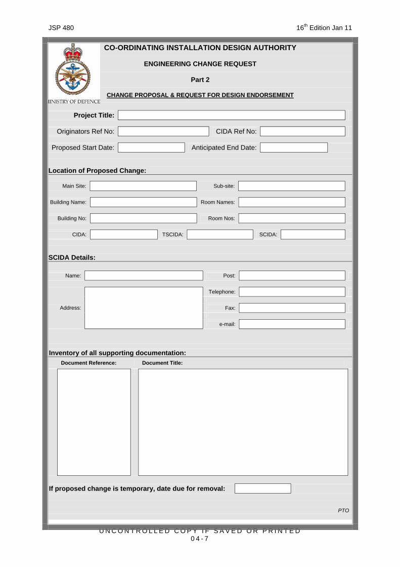
ECR Part 2 ~ Change Proposal & Request for Design Endorsement
0411. Part 2 is used to provide detailed design proposals to CIDA in order to obtain CIDA approval and is to include all relevant detail and a comprehensive list of all statutory requirements, standards, codes of practice, equipment specific installation requirements, reports and guidance that the proposed ‘change’ will comply with in sufficient detail to allow CIDA to assess whether the ‘change’ is likely to meet the necessary requirements. (Drawings detailing the proposal, in accordance with the requirements of Chapter 12, are normally required to support this activity). For minor changes, Parts 1 & 2 may be combined.
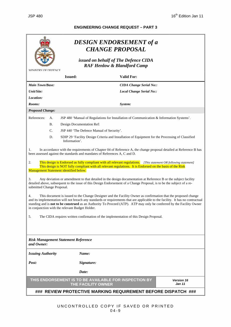
ECR Part 3 ~ Design Endorsement of a Change Proposal
0412. If the design of the change proposal is in accord with all CIDA requirements, the ‘change’ is endorsed and Part 3 will be issued to the Installation Design Authority (IDA). The Part 3 will always have a time limitation imposed, normally 6 months, to maintain effective configuration management. If the proposed change does not meet all requirements, SCIDA will liaise with the designer to achieve conformance.
0413. The ECR Part 3 is issued to the design agency as confirmation that the proposed change and its implementation will not breach any standards or requirements that are applicable to the subject facility. It has no contractual standing and is not to be construed as an Authority To Proceed (ATP). ATP may only be conferred by the facility owner in conjunction with the relevant budget holder.
ECR Part 4 ~ Installation Completion Statement
0414. Part 4 of the ECR process requires a statement from the IDA that the ‘change’ has been completed in accordance with the endorsed design and CIDA installation standards. Neither the ‘change’ itself, nor any associated contracts are to be considered as being complete until 'As Fitted' configuration management drawings, in AutoCAD compatible format, have been approved by and lodged with the SCIDA. The Change Implementer or Change Designer shall
JSP 480 16th Edition Jan 11
U N C O N T R O L L E D C O P Y I F S A V E D O R P R I N T E D 0 4 - 3
liaise with SCIDA to enable SCIDA assessment of the physically completed change before the Change Implementer leaves the site.
ECR Part 5 ~ Certificate of Installation Conformance
0415. If, after inspection, all aspects of the installed ‘change’ are considered by CIDA to be satisfactory and in conformance with all requirements, the ‘change’ will be signed off as being conformant by the issue of Part 5 of the ECR process.
Non-Compliance & Risk Management
0416. If, during the change control cycle, a non-compliance with any relevant regulation is identified, it must be confirmed whether, under existing Health & Safety at Work Regulations as defined in Statutory Instruments (SI), there is an Absolute Duty to Comply with those Regulations. Where an Absolute Duty to Comply exists, the non-compliance must be rectified prior to handover of the system. The SCIDA is to provide full written detail of the non-compliance to the Change Initiator. In such cases where rectification is delayed, the Duty Holder, normally the Head of Establishment shall be made aware of the non-compliance.
0417. In other cases, where there is no Absolute Duty to Comply, and all avenues of resolution have been exhausted, then that non-compliance may be risk managed. The SCIDA is to provide full written detail of the non-compliance, including any detrimental effect the non-compliance may have on other CIS, to the Change Initiator. The Change Initiator, with assistance from and agreement of SCIDA, shall identify the appropriate Risk Owner. Where there is contention, Defence CIDA shall arbitrate. The Risk Owner shall consider the full impact of the non-compliance before accepting or declining the associated risk.
0418. An accepted risk shall be formalised by a Risk Management Statement which is to be referenced by and become part of the CIDA Design Endorsement or Installation Conformance Certificate. A declined risk shall be formalised by the Risk Owner providing direction, relative to the resolution of the risk, to the Change Initiator.
Retrospective Engineering Change Request
0419. A Retrospective ECR (RECR) is to be raised when a ‘change’ is suspected to have occurred without the required CIDA approval process having taken place. Submission of an RECR will ensure that, where required, the ring-fence around a facility can be adjusted to prevent a repeat of similar unauthorised ‘change’ in the future. The RECR procedure will also attempt to identify those responsible for any remedial work necessary to correct installations that either fall below acceptable standards or where a CIDA authorised installation or the CIDA overall plan for a facility is compromised.
CIDA Approval for Future Use
0420. When a requirement exists to retain cable, spare capacity or equipment for future use, a CIDA Approval for Future Use (CAFU) form shall be submitted to CIDA. CIDA will authorise retention or require recovery as appropriate, after taking account of any formal agreements with other authorities who have a vested interest. A CAFU number must be obtained, before any unused CIS equipment or cables are left in-situ.
CIDA Unsatisfactory Feature Report
0421. Installations may exist that do not fully meet all CIDA requirements as mandated by this publication. These installations will be evaluated on a case by case basis through the CIDA Unsatisfactory Feature Report (CUFR) process and concessions agreed or remedial action initiated as deemed appropriate. All concessions should be logged for future reference
JSP 480 16th Edition Jan 11
U N C O N T R O L L E D C O P Y I F S A V E D O R P R I N T E D 0 4 - 4
and tracking. Minor non conformances may be retained under VfM if they have no impact on H&S or Security. In all other cases, any future Change proposals for that installation are to include corrective actions sufficient to bring the installation into full compliance with CIDA Installation Standards.
CIDA Quick Reaction Fax Approval
0422. Utilisation of a Quick Reaction Fax Approval (QRFA) is in itself a commitment that the Change Designer will initiate full ECR procedure within 10 working days and, when the full ECR has been processed, the Change Initiator will manage the implementation of any modification that is necessary to bring the installation into conformance with CIDA requirements. This caveat is necessary because imposed time constraints may preclude detailed assessment of the proposal. The following are acceptable situations appropriate to the use of a QRFA:
a. Where a proposed ‘change’ could not have been foreseen and is required in response to an Urgent Operational Requirement (UOR) or Urgent Engineering Requirement (UER).
b. In exceptional circumstance where it is deemed to be overwhelmingly beneficial to MOD.
0423. In extreme circumstances, a change may take place without even a QRFA. The commitments mandated by the use of the QRFA will also apply.
DOCUMENTATION AVAILABILITY
0424. A full set of documentation detailing all applicable statutory requirements, standards, codes of practice, maintenance procedures, system design, installation design and equipment specific installation requirements, is to be available locally following all changes to all CIS facilities. Additionally, SCIDA is to hold ‘As Fitted’ drawings and connectivity data relating to the facilities affected by the change.
ADDITIONAL REQUIREMENTS RELATING TO C-E FACILITIES
0425. The following aspects of CM are frequently overlooked by organisations submitting change proposals that effect C-E or C4I hardware, its environment or Radio Site Restriction Zones. All proposals that effect these aspects are to be brought to the attention of MOD-RSP at the earliest possible stage of a change:
a. Radio Site Clearance and Safeguarding.
b. MOD Register of Radio Sites.
c. Site Plans or Navigation Aid, Radar and Radio, Location Maps.
Radio Site Clearance, Site Safeguarding & MOD Register of Radio Sites
0426. All requirements to apply change to Radio Frequency (RF) emitters/receivers on MOD facilities must include an early application, in accordance with JSP 846 ‘MOD Radio Site Clearance and Protection ~ UK’, to MOD-RSP for approval, Radio Site Clearance and amendment of the Register of Radio Sites (RRS). Information on any RF propagation path safeguarding requirements must be included in these applications to enable protection, for each facility, against degradation by future development or installation.
JSP 480 16th Edition Jan 11
U N C O N T R O L L E D C O P Y I F S A V E D O R P R I N T E D 0 4 - 5
CO-ORDINATING INSTALLATION DESIGN AUTHORITY
ENGINEERING CHANGE REQUEST
Part 1
INITIAL PROJECT INFORMATION
Project Title:
Originators Ref No: CIDA Ref No:
Proposed Start Date: Anticipated End Date:
Sites That Will Be Effected By Proposed Change: First Site
Main Site: Sub-site:
Building Name: Room Names:
Building No: Room Nos:
CIDA: TSCIDA: SCIDA:
Second Site Main Site: Sub-site:
Building Name: Room Names:
Building No: Room Nos:
CIDA: TSCIDA: SCIDA:
Third Site
Main Site: Sub-site:
Building Name: Room Names:
Building No: Room Nos:
CIDA: TSCIDA: SCIDA:
If more than three sites are effected please attach additional sheet(s)
Overview of Proposed Change: Main System(s) Involved: Synopsis of Work:
If proposed change is temporary, date due for removal:
PTO
JSP 480 16th Edition Jan 11
U N C O N T R O L L E D C O P Y I F S A V E D O R P R I N T E D 0 4 - 6
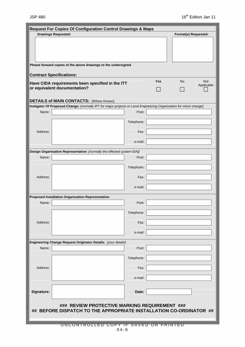
Request For Copies Of Configuration Control Drawings & Maps Drawings Requested: Format(s) Requested:
Please forward copies of the above drawings to the undersigned Contract Specifications:
Have CIDA requirements been specified in the ITT or equivalent documentation?
Yes
No
Not Applicable
DETAILS of MAIN CONTACTS: [Where Known] Instigator Of Proposed Change: [normally IPT for major projects or Local Engineering Organisation for minor change]
Name: Post:
Telephone:
Fax: Address:
e-mail:
Design Organisation Representative: [normally the effected system IDA]]
Change Designers Details & Statement of Conformance:
Name: Post:
Telephone:
Fax:
Address:
e-mail:
This proposal conforms with the requirements of JSP 440 & JSP 480 as amended by any specific CIDA requirements established in response to Part 1. Other Designers with a vested interest, as notified by CIDA, are content with this proposal.
Date: Signature:
### REVIEW PROTECTIVE MARKING REQUIREMENT ### ## BEFORE DISPATCH TO THE APPROPRIATE INSTALLATION CO-ORDINATOR ##
JSP 480 16th Edition Jan 11
U N C O N T R O L L E D C O P Y I F S A V E D O R P R I N T E D 0 4 - 9
ENGINEERING CHANGE REQUEST – PART 3
DESIGN ENDORSEMENT of a CHANGE PROPOSAL
issued on behalf of The Defence CIDA RAF Henlow & Blandford Camp
Issued: Valid For:
Main Town/Base: CIDA Change Serial No::
Unit/Site: Local Change Serial No::
Location:
Rooms: System:
Proposed Change:
References: A. JSP 480 ‘Manual of Regulations for Installation of Communication & Information Systems’.
B. Design Documentation Ref:
C. JSP 440 ‘The Defence Manual of Security’.
D. SDIP 29 ‘Facility Design Criteria and Installation of Equipment for the Processing of Classified Information’.
1. In accordance with the requirements of Chapter 04 of Reference A, the change proposal detailed at Reference B has been assessed against the standards and mandates of References A, C and D.
2. This design is Endorsed as fully compliant with all relevant regulations. [This statement OR following statement] This design is NOT fully compliant with all relevant regulations. It is Endorsed on the basis of the Risk Management Statement identified below.
3. Any deviation or amendment to that detailed in the design documentation at Reference B or the subject facility detailed above, subsequent to the issue of this Design Endorsement of a Change Proposal, is to be the subject of a re-submitted Change Proposal.
4. This document is issued to the Change Designer and the Facility Owner as confirmation that the proposed change and its implementation will not breach any standards or requirements that are applicable to the facility. It has no contractual standing and is not to be construed as an Authority To Proceed (ATP). ATP may only be conferred by the Facility Owner in conjunction with the relevant Budget Holder.
5. The CIDA requires written confirmation of the implementation of this Design Proposal.
Risk Management Statement Reference and Owner:
Issuing Authority
Post:
Name:
Signature:
Date:
THIS ENDORSEMENT IS TO BE AVAILABLE FOR INSPECTION BY THE FACILITY OWNER
Version 16 Jan 11
### REVIEW PROTECTIVE MARKING REQUIREMENT BEFORE DISPATCH ###
JSP 480 16th Edition Jan 11
U N C O N T R O L L E D C O P Y I F S A V E D O R P R I N T E D 0 4 - 1 0
CO-ORDINATING INSTALLATION DESIGN AUTHORITY
ENGINEERING CHANGE REQUEST
Part 4
INSTALLATION COMPLETION STATEMENT
Project Title:
Originators Ref No: CIDA Ref No:
Actual Start Date: Completion Date:
Location of Change:
Main Site: Sub-site:
Building Name: Room Names:
Building No: Room Nos:
CIDA: TSCIDA: SCIDA:
CIDA/SCIDA Details:
Name: Post:
Telephone:
Fax:
Address:
e-mail:
Change Implementers Details & Certificate of Completion:
Name: Post:
Telephone:
Fax:
Address:
e-mail:
Except for this Risk Management Statement, the proposal at Part 2 of this ECR has been completed in conformance with the requirements of JSP 440 & JSP 480.
Date by which ‘As Fitted’ drawings will be lodged with CIDA:
Date: Signature:
### REVIEW PROTECTIVE MARKING REQUIREMENT ### ## BEFORE DISPATCH TO THE APPROPRIATE INSTALLATION CO-ORDINATOR ##
JSP 480 16th Edition Jan 11
U N C O N T R O L L E D C O P Y I F S A V E D O R P R I N T E D 0 4 - 1 1
ENGINEERING CHANGE REQUEST – PART 5
CERTIFICATE of INSTALLATION CONFORMANCE
issued on behalf of The Defence CIDA RAF Henlow & Blandford Camp
Certificate Number: Dated:
Main Town/Base:
Unit/Site: Local Change Serial No:
Location:
Rooms: System:
Certificated Change
References: A. JSP 480 ‘Manual of Regulations for Installation of Communication and Information Systems’
B. JSP 440 ‘The Defence Manual of Security’
C. SDIP 29 ‘Facility Design Criteria and Installation of Equipment for the Processing of Classified Information’
D. Design Proposal Documentation Ref
E. CIDA Design Endorsement:
F. Installation Completion Statement:
1. In accordance with the requirements, standards and mandates of References A to C, the Change (Reference D), as Endorsed (Reference E) and Confirmed as complete (Reference F), has been Inspected.
2. The implementation of the subject Change is fully compliant with all relevant regulations, and is therefore deemed conformant. [This statement OR following statement] The implementation of the subject Change is NOT fully compliant with all relevant regulations. It is accepted on the basis of the Risk Management Statement detailed below.
3. The continued conformance of the completed installation is dependent on no uncontrolled changes being implemented. Any changes, subsequent to the issue of this Certificate of Installation Conformance, requires a Change Proposal to be raised in accordance with the requirements of Chapter 04 Reference A.
Risk Management Statement Reference and Owner:
Issuing Authority
Post:
Name:
Signature:
Date:
THIS CERTIFICATE IS TO BE RETAINED BY THE SYSTEM SECURITY OFFICER
Version 16 Jan 11
### REVIEW PROTECTIVE MARKING REQUIREMENT BEFORE DISPATCH ###
JSP 480 16th Edition Jan 11
U N C O N T R O L L E D C O P Y I F S A V E D O R P R I N T E D 0 5 - 1
CHAPTER 05
LIMITED FIRE HAZARD CABLES & MATERIALS
INTRODUCTION
0501. Cables rarely initiate fires, but they could be involved in them and can significantly increase the damage caused should they propagate the fire. Until recently the flame retarding of cables was achieved by the use of halogenated flame retardants which are effective fire suppressants, but which unfortunately produce dense smoke and corrosive acid gases when burned. These effects are highly undesirable in a fire, hindering evacuation and fire fighting, endangering life and causing corrosion damage to expensive and vital equipment.
0502. The terms Limited Fire Hazard (LFH), Low Smoke & Fume (LSF), Low Smoke Halogen Free (LSHF) and Low Smoke Zero Halogen (LSZH) (LS0H) are used as both descriptors and as industry trade marks. Many Standards exist for LFH cables and cable containment systems and the methods to be used to quantify test criteria.
DEFINITION OF LIMITED FIRE HAZARD MATERIALS
0503. The attributes inferred on a particular material do not automatically qualify it for installation into a particular facility. Irrespective of a material’s descriptor, if it has not been included in the CIDA Fire Hazard Materials Database (FHMD), then it must not be used in MOD facilities where specific LSZH standards have been specified.
0504. To meet MOD FH standards and therefore qualify for inclusion in the CIDA FHMD, a material must meet all of the stringent standards for Flammability, Smoke, Acidity, Toxicity and Halogen Content illustrated in Table 5-1. It should be noted that the standards quoted are typical and not the only ones that can prove conformance with MOD requirements.
Table 5-1 Test Methods LFH Requirements
LSZH Requirements
Flammability
BS EN 60332
A method of testing a single vertical wire or cable under fire conditions. The char length of a vertical test specimen, exposed to a gas burner in a suitable chamber, is measured.
Charing > 5 cm < 54 cm below top cable support
Smoke
BS EN 61034
The test specimen is subjected to an alcohol flame within a closed chamber, 27 m3 in volume. The smoke density is measured by means of a photometric system thus enabling light transmittance through the smoke to be quantified.
Minimum light transmittance:
60%.
Acidity
IEC 60754
Fire effluent, evolved from the pyrolysis or combustion of a test specimen, is bubbled through distilled or demineralised water. The pH, or pH and conductivity, of the resulting aqueous solution is then measured.
Not Applicable
pH > 4.3
Conductivity: ≤ 10μS/mm
Toxicity
Def Stan 02-713
The concentration of each of the possible by-products of pyrolysis or combustion is assessed, and, by measurement and numerical summation of the toxicity factors, a Toxicity Index (TI) is assigned.
Not Applicable
Insulation: TI ≤ 0.2 Sheaths TI ≤ 5.0
JSP 480 16th Edition Jan 11
U N C O N T R O L L E D C O P Y I F S A V E D O R P R I N T E D 0 5 - 2
Halogen Content
BS EN 50267-2-2
Material is tested for potential acid gas evolution by using the Lassaigne Test (sodium fusion test). The test is designed to detect the presence of halogens (fluorine, chlorine, bromine or iodine) when a small sample of the material is subjected to combustion and pyrolysis.
Not Applicable
Zero Halogens Detected
THE MOD PERSPECTIVE
0505. MOD facilities containing CIS range from small, isolated, single room buildings with multiple escape routes, to complex multi-room underground bunkers with limited means of egress. CIS assets within these facilities can range from a single stand-alone management support PC, with no operational significance, to large multi-cabinet systems which are operationally essential. Equally, to reflect MOD business, various working arrangements are practised across the MOD estate, and include ‘9 to 5’ working, 24/7 manning and cases where staff ‘live in’. It is within this context that the MOD perspective on the fire hazard of cables and materials is considered.
0506. MOD policy is designed to limit the fire threat posed by cable and cable containment in all buildings on the MOD Estate by controlling the spread of fire and fumes and minimising the formation of acrid smoke and toxic gases by specifying the use of non hazardous, low flammability materials wherever reasonably practicable.
0507. For underground or windowless (un-fenestrated) facilities with limited means of escape and forced air ventilation, Crown Fire Standard E8, ‘Underground Accommodation,’ requires that ‘All cables shall be flame retardant cables of the low smoke and fume emission type. Cable bedding and sheathing materials shall be of the low smoke, low or zero halogen type (LSZH).’ MOD policy requires that system cables, cabinet wiring and mains voltage power cables for computer & office equipment are to be constructed from LSZH materials.
0508. If the facility is also subject to sleeping or Close-Down activity, then all cables associated with telephones; computer keyboards, mice and other peripherals; and all plastics, including equipment cases, furniture and office related items are to be provided in LSZH materials if they are available at reasonable cost.
0509. For electronic and network equipment rooms, Crown Fire Standard E7, ‘Electronic Data Processing Accommodation,‘ references BS 6266:2002, ‘Code of practice for fire protection for electronic equipment installations,’ which states at Clause 6.4, ‘Power and data cables should not propagate fire readily, nor produce large quantities of smoke or corrosive gases.’ MOD policy requires that system cables, cabinet wiring and mains voltage power cables for computer & office equipment are to be constructed from LSZH materials.
0510. One of the most important fire related aspects of CIS installations is correct maintenance of the fire-integrity of fire barriers that are subject to cable penetration, BS 7671 Clause 527.2 refers. All walls and all floors in MOD bunkers and some walls and all floors in other MOD facilities are classed as fire barriers (with a fire integrity rating) and thus require an equivalent rated fire-stopping and/or penetration sealing system that will maintain the original fire integrity of the fire barrier, to be utilised at all penetrations.
0511. Table 5-2 embraces those MOD policy requirements from the preceding paragraphs.
JSP 480 16th Edition Jan 11
U N C O N T R O L L E D C O P Y I F S A V E D O R P R I N T E D 0 5 - 3
Table 5-2 Fire Stopping
and/or Penetration
Sealing System
System Cables,Cabinet Wiring& Non-Metallic
Cable Containment
Office Equipment Power Cables
SupplementaryEquipment
Wiring & Equipment
Cases etc
Underground or Windowless
Facilities Subject to
Close-Down Activity1
All Walls &
All Floors LSZH LSZH
LSZH if available at
reasonable cost
Underground or Windowless
Facilities NOT Subject to
Close-Down Activity1
All Walls &
All Floors LSZH LSZH
LFH unless
LSZH policy is easy to implement
Electronic &
Network Equipment Rooms2,5
All Walls &
All Floors LSZH LSZH LFH
All Other Buildings, Including
Small Enclosed Buildings, ISO Containers & Vehicles
Some Walls3 &
All Floors LFH4 LFH LFH
Notes:
1. Policy for these facilities is predicated on minimising fire & toxic effluent primarily for protection of personnel.
2. Policy for these facilities is predicated on minimising fire & acidic effluent primarily for protection of equipment.
3. Fire Barrier detail for specific facilities is obtainable from the relevant Responsible Person (Fire Safety). (SI 2005 No. 1541, The Regulatory Reform (Fire Safety) Order 2005, Article 3 refers)
4. Where communications cables traverse Means of Escape routes, use of LSZH is dictated by the policy for continuous unbroken cable from the NER5 (where LSZH materials are specified) through to the TAP. Other cables within Means of Escape routes are not mandated to be LSZH, however, their use is encouraged.
5. An NER (Network Equipment Room) is defined as any room with Network Equipment as its primary occupancy.
PROCESS FOR INSTALLATION AGREEMENT
0512. Any cable or containment whose data sheet confirms product compliance with the Fire Hazard policy indicated in Table 5-2 may be selected for use in MOD facilities. However, where policy indicates use of an LSZH product, installation is not to commence unless the detail of the material and evidence confirming compliance is included in the CIDA FHMD, without first obtaining either:
a. Product compliance confirmation and installation agreement from CIDA or,
b. An installation concession, granted by the Defence Estates Professional and Technical Services (DE PTS), Senior Fire Safety Manager (SFSM).
JSP 480 16th Edition Jan 11
U N C O N T R O L L E D C O P Y I F S A V E D O R P R I N T E D 0 5 - 4
Requests for Compliance Confirmation
0513. If it is believed that a proposed material complies with the CIDA FH requirement but is not listed in the CIDA FHMD, a copy of the appropriate manufacturer’s datasheet along with any supporting standards information must be provided to CIDA before installation of the material. Where CIDA agrees that the information supplied substantiates compliance, the material may be installed and the detail added to the Database to inform future compliance agreement.
Requests for Installation Concession
0514. When the proposed material is not listed in the CIDA FHMD and the standards quoted in the manufacturer’s data-sheet are not considered to be adequate, then a concession for installation of the material may be applied for from the SFSM. Each application for a concession must include a request to the SFSM that the departmental ruling is copied to CIDA with a recommendation regarding inclusion of the detail in the CIDA FHMD.
LEGACY INSTALLATIONS
0515. Whilst the above policy is mandated for all changes effecting existing facilities and all new build projects, within those facilities where Crown Fire Standards E7 or E8 applies and existing wires, cables, cable containment and materials are not compliant, the MOD SFSM and the CIDA are to be requested to conduct an audit and establish a rectification strategy to identify replacement priorities.
POLICY ASSISTANCE
0516. Assistance with the implementation of this policy may be obtained from the SCIDA Help Desk.
JSP 480 16th Edition Jan 11
U N C O N T R O L L E D C O P Y I F S A V E D O R P R I N T E D 0 6 - 1
CHAPTER 06
THE CIS PHYSICAL ENVIRONMENT
INTRODUCTION
0601. It is desirable that the installation of any CIS into any area will have a net zero impact on the environment of the immediate area. To this end, the environmental impact, particularly in terms of space, heat and noise output, of the addition of CIS is to be fully explored and measures put in place to negate any deleterious effect.
0602. An executive summary of the principal factors to be considered when planning the accommodation of Information Technology (IT) equipment, with cross-references to more detailed information, in the form of requirements of people and equipment; typical classes of accommodation; recommendations for special environments and circumstances; guidance on interpretation of recommendations from other bodies, can be found at:
a. BS 7083:1996 ‘Guide to The accommodation and operating environment for Information Technology (IT) equipment’.
0603. The standard covers construction and accessibility; environmental conditions; electrical power requirements; operational safety and security by giving guidance on the accommodation and operating environment within which IT equipment and associated services are installed. Requirements pertinent to MOD CIS are detailed below.
0604. To ensure that equipment placement, cooling, power and earthing aspects do not require re-engineering as requirements evolve, all equipment cabinets, including those that are in essence a single equipment (such as USAS II or CCIS Server cabinets), are to be installed in accordance with the requirements of this publication.
MAIN EARTHING TERMINAL OR BUS-BAR
0605. A main earthing terminal (MET) or bus-bar is provided for the connection of protective bonding conductors, earthing conductors, protective conductors and functional earthing conductors, if relevant, to the means of earthing and is typically found installed in building entrance facilities, communications rooms, network equipment rooms and cabinets. The location of an MET shall be accessible. If the location of the MET is hidden or not easily accessible (e.g. under a raised floor or above a suspended ceiling) then a label indicating its location shall be provided in an accessible position and in close proximity to the MET. Each conductor shall be able to be disconnected individually and the connection to the MET shall be reliable and disconnectable only by means of a tool.
0606. A typical MET is fabricated of solid hard drawn copper, approximately 6 mm thick, 32 mm wide and 300 mm long or of sufficient length for immediate requirements and a 20% allowance for future growth. An MET or bus bar in an equipment cabinet will normally be constructed of solid hard drawn copper, approximately 6 mm thick, 16 mm wide and run for the full height of the cabinet. However, a solid metal structural element of the framework of a cabinet may be utilised as an MET if it simultaneously satisfies the following three requirements:
a. The electrical continuity shall be assured by construction so as to ensure protection against mechanical, chemical or electrochemical deterioration;
b. The material and dimensions provide electrical characteristics not less than that of the cabinet CPC;
JSP 480 16th Edition Jan 11
U N C O N T R O L L E D C O P Y I F S A V E D O R P R I N T E D 0 6 - 2
c. It shall provide a clean flat metallic surface for the connection of protective conductors which shall present a junction resistance no greater than 0.05 ohms.
EQUIPMENT MOUNTING AND STACKING
0607. Unless manufacturers’ installation design standards specifically allow, equipment designed for desk-top or shelf mounting is not to be stacked. This applies wherever the equipment is to be located. Units designed for stacking shall not be mounted more than 2 equipments high without SCIDA agreement. Dissimilar sized units shall not be stacked. Where desk-top or shelf mounting is desired, cable management, shall be applied along the complete cable length. Whenever there is a perceived requirement to stack desk-top or shelf mounting units not designed for stacking, suitable shelving must be used and this will normally be within an equipment cabinet. For situations where a small number of these items require mounting and 19 inch rack shelving is not appropriate, low-profile wall cabinets are recommended.
0608. To maximise the available capacity within a cabinet designed for 19 inch rack mounted equipment, where possible, equipment should only be located at complete U intervals. For the installation of a particular equipment, other intervals may be used where that positioning would maximise useable rack space.
EQUIPMENT CABINETS
0609. All cabinets are to conform to the following standards:
a. BS EN 60297-3-100:2009 ‘Mechanical structures for electronic equipment Dimensions of mechanical structures of the 482,6 mm (19 in) series Basic dimensions of front panels, sub racks, chassis, racks and cabinets’.
b. BS EN 60950-1:2006 ‘Information technology equipment-Safety ~ General requirements’.
0610. In addition, equipment cabinets are to provide protection to both equipment and personnel relevant to the physical environmental conditions of the installed location, in accordance with the requirements of the following European Standard:
a. BS EN 60529:1992 ‘Degree of protection provided by enclosures (IP code)’.
0611. Cabinets are to have metal or glass doors, which must be lockable by a common key. Lockable glass front, and metal rear door is the preferred configuration. Cabinets intended for rack mount test & measuring equipment do not need to be fitted with a front door unless required for cooling or EMC purposes. A fitted front door remains the preferred configuration even for test and measurement use.
0612. All cabinets are to be installed complete with the following:
a. An internal power outlet block, complete with an external earth terminal, of sufficient capacity to supply all equipment in a fully populated rack. 12 power outlets shall be a minimum for racks of 42U in height, or greater. There shall always be at least 2 spare power outlets following initial rack population.
b. An MET (see paragraph 0606) of sufficient size and placement to allow all cabinet components and all installed equipment to be independently bonded with minimal length bonding straps.
JSP 480 16th Edition Jan 11
U N C O N T R O L L E D C O P Y I F S A V E D O R P R I N T E D 0 6 - 3
c. An internal cable management system of sufficient capacity to manage the cabling of a fully populated cabinet, including possible TEMPEST/EMC separation requirements.
d. Front and rear equipment attachment vertical members that are mounted such that sufficient space is available for equipment handles, cable connectors and the necessary bend radii of both fibre optic and metallic cables to allow the cabinet doors to close without pressing against cables, connectors, etc.
e. A suitably placed identification label for recording information, including a unique cabinet identifier and, for CONFIDENTIAL and above, the highest protective marking being processed within. Additionally, it is recommended that the cabinet identification labelling include detail of the power supply to the cabinet. Note: if power supply detail is not included in the cabinet identification label it must be provided in a clearly visible manner elsewhere on the cabinet.
0613. To assist with future proofing and the flexibility of a facility, and to ensure maintainable inter-cabinet cable routing, individual cabinets that are destined to be installed alongside other cabinets are, wherever possible, to retain their side panels in situ. Retention of correctly bonded side panels will also assist with EMC/TEMPEST screening, even though such screening may not be a requirement at the time of installation.
0614. All new installations of cabinets shall fit in with the ergonomics and aesthetics of the associated area and provide optimum spare capacity to assist in the economic use of the available space. For example, full height as opposed to half height cabinets shall be provided and these shall be positioned in accordance with the SCIDA’s overall plan for the facility. Additions to extant suites of equipment cabinets shall, within the above constraints and requirements, conform to the design and colour scheme of the existing cabinets.
STABILITY
0615. Requirements for the stability and safety of work equipment are specified in the following documents:
a. SI 1998 No 2306 ‘The Provision and Use of Work Equipment Regulations’.
(1) Regulation 20, ‘Work equipment or part of work equipment is stabilised by clamping or otherwise where necessary for purposes of health and safety’.
b. BS EN 60950-1:2006, ‘Information technology equipment-Safety ~ General requirements’.
(1) Clause 4.1 ‘Stability’.
(2) Clause 4.2.10 ‘Mechanical Strength’, ‘Wall or Ceiling Mounted Equipment’.
0616. All installations are to meet the requirements of BS EN 60950-1. Floor mounted equipment cabinets are to meet the requirement of Clause 4.1 by being securely fixed to the fabric of the building in a manner appropriate to the material and structure and the total weight and distribution of equipment that may be installed in a fully populated enclosure. When racks are mounted on a false floor, proprietary rack fixing systems designed for this facility may be employed providing the manufacturer’s instructions are followed and the floor is checked for suitability beforehand. To provide additional stability, and wherever possible, enclosures mounted immediately adjacent to one another are to be secured together using
JSP 480 16th Edition Jan 11
U N C O N T R O L L E D C O P Y I F S A V E D O R P R I N T E D 0 6 - 4
approved fixtures and fittings. All wall and ceiling mounted CIS equipment is to be certified as meeting the requirement of Clause 4.2.10.
0617. Unless a cabinet has an integral plinth, a timber mounting plinth is to be used at all locations not having raised access floors (modular computer floors). Where cabinets are mounted on raised access floors, the overall design and installation/maintenance procedures are to ensure safety from all perspectives including the stability, functionality and strength of the design when floor panels are removed to allow access to under-floor cables and plant. The required characteristics and performance standards for raised access floors can be found at:
a. BS EN 12825:2001 ‘Raised access floors’.
0618. All equipment installed within a cabinet is to be secured against unintentional movement by the use of approved brackets, shelving, slides or runner assemblies as necessary, according to the size, weight and design of the equipment. The use of cable ties or ‘Velcro’ for securing small items that do not have a recognised ‘rack mount adaptor’ accessory may be permitted provided there is no risk to the installation.
IMPACT ON AMBIENT TEMPERATURE
0619. Cabinet internal air temperatures are not to exceed 5ºC above the related ambient room temperature and in all circumstances are to be kept below 40ºC. Office accommodation, as opposed to equipment rooms, shall not have equipment installed that would cause the room temperature to become uncomfortable or to rise above 30ºC. The Change initiator whose change would cause higher temperatures is responsible for resolving the problem.
MANUFACTURERS’ INSTALLATION STANDARDS
0620. Whenever possible, manufacturers’ installation standards are to be provided to SCIDA at the design proposal stage of an installation. These should identify aspects such as cooling requirements, ventilation space requirements or EMC issues that may require safeguarding by SCIDA throughout the in-service life of the equipment.
SPACE & ACCESSIBILITY
0621. SI 1989 No 635 ‘The Electricity at Work Regulations’ requires at:
a. Regulation 15 ‘For the purposes of enabling injury to be prevented, adequate working space, adequate means of access, and adequate lighting shall be provided at all electrical equipment on which or near which work is being done in circumstances which may give rise to danger’.
0622. BS 7083:1996 ‘Guide to the accommodation and operating environment for IT equipment’ recommends at:
a. Clause 5.8 ‘access to equipment should always be provided for maintenance, with passageways, in front and behind, of the following dimensions: a. where access is required to the rear, not less than 900 mm wide for a single row of equipment; b. between two rows of equipment, a minimum of 1350 mm’.
0623. BS EN 50174-1:2009 ‘Information technology — Cabling installation ~ Installation specification and quality assurance’ requires at:
JSP 480 16th Edition Jan 11
U N C O N T R O L L E D C O P Y I F S A V E D O R P R I N T E D 0 6 - 5
a. Clause 4.2.5.1 ‘The location of cabinets, frames and racks shall provide a minimum clearance of 1,2 m on all faces where access is required’.
0624. MOD policy for compliance with the foregoing apparent confliction requires that:
a. Single cabinets and single rows of cabinets are to be installed such that all doors, where access is required, may be opened through a full 90 degrees and unobstructed access to the interior is provided or an unobstructed clearance of 1.2 metres is provided, whichever is the greater.
b. Multiple rows of cabinets are to be installed such that an unobstructed passageway, at least 1350 mm wide, is preserved between rows.
c. Wall mounting double hinged cabinets are to be installed such that the equipment containment portion of the cabinet may be opened through a full 90 degrees and are to be positioned such that they pose no Health & Safety hazard.
0625. Clearance distances are to be increased by an appropriate figure in situations where equipment that is designed to be withdrawn on runners or particularly heavy or bulky equipment is to be accommodated.
IT FURNITURE
0626. IT furniture is a generic term for office desks that incorporate provision for electrical power, data and telecommunications distribution systems. All IT furniture in MOD facilities shall conform to, and be installed, inspected, tested and maintained in accordance with, the requirements of the following two documents:
a. BS 6396:2008 'Electrical systems in office furniture and educational furniture – Specification’.
b. JSP 375, Volume 2, Leaflet 12, Annex A, Appendix 1, 'Inspection and Testing of Portable Electrical Appliances'.
ADDITIONAL REQUIREMENTS
0627. In addition to the guidance contained within this chapter, all CIS used for storing, forwarding or processing MOD information is to be installed in accordance with the appropriate mandates of:
a. JSP 440, ‘The Defence Manual of Security’.
b. SDIP 29, ‘Facility Design Criteria and Installation of Equipment for the Processing of Classified Information’.
QUICK GUIDE
0628. All Cabinets are to be securely fixed to the fabric of the building.
0629. All equipment installed within a cabinet is to be secured against unintentional movement.
0630. All cabinets are to be fitted with an MET (see paragraph 0606) to allow all cabinet components and all installed equipment to be independently bonded.
0631. All cabinets are to be fitted with a power outlet block of sufficient capacity to supply all equipment in a fully populated rack.
JSP 480 16th Edition Jan 11
U N C O N T R O L L E D C O P Y I F S A V E D O R P R I N T E D 0 6 - 6
0632. All Cabinets containing equipment processing MOD information protectively marked CONFIDENTIAL or above are to clearly identify the highest protective marking being processed.
JSP 480 16th Edition Jan 11
U N C O N T R O L L E D C O P Y I F S A V E D O R P R I N T E D 0 7 - 1
CHAPTER 07
THE CIS ELECTRICAL ENVIRONMENT
INTRODUCTION
0701. All Cabinet electrical systems are to be designed, installed and certified in accordance with the requirements of:
a. BS 7671:2008 ‘Requirements for Electrical Installations ~ IEE Wiring Regulations’.
0702. BS 7671 has been extensively referred to in Health and Safety Executive (HSE) guidance over the years. Electrical installations that conform to this standard are regarded by the HSE as likely to achieve conformity with the relevant parts of the Electricity at Work Regulations 1989.
0703. The following paragraphs, therefore, are provided to tailor and highlight the requirements from the MOD perspective. Compliance with the requirements of this chapter will ensure that cabinet installations meet Health & Safety legal mandates whilst providing the MOD with durable and flexible CIS.
BONDING & EARTHING
0704. The subject of bonding and earthing conductors is fully examined, with requirements identified, at:
a. BS 7671:2008 ‘Requirements for Electrical Installations ~ IEE Wiring Regulations’, Chapter 54 ‘Earthing Arrangements and Protective Conductors’.
0705. SI 1989 No 635 ‘The Electricity at Work Regulations’ requires at:
a. Regulation 8 ‘Precautions shall be taken, either by earthing or by other suitable means, to prevent danger arising when any conductor (other than a circuit conductor) which may reasonably foreseeably become charged as a result of either the use of a system, or a fault in a system, become so charged’,
b. Regulation 9 ‘If a circuit conductor is connected to earth or to any other reference point, nothing which might reasonably be expected to give rise to danger by breaking the electrical continuity or introducing high impedance shall be placed in that conductor unless suitable precautions are taken to prevent that danger’.
0706. To comply with Regulations 8 & 9, all parts of the cabinet, including doors, side panels and blanking panels are to be individually bonded to the cabinet MET (see paragraph 0606) by insulated multi-strand flexible cables with cross sectional area not less than 4 mm²
(or 2.5 mm² if mechanical protection in addition to green/yellow insulation is provided). Additional bonding is to be made to all equipment cases provided with an earth terminal unless the terminal is provided for Functional Earthing (FE), in which case FE paragraphs 0708 and 0709 apply. Earthing is to be provided to connect each PDU earth terminal to the cabinet MET.
Requirement for a Second Circuit Protective Conductor
0707. Provided that there are no plug/socket combinations in the power feed to a cabinet and the Circuit Protective Conductor (CPC) meets the requirements of BS 7671 and is not less than 2.5 mm², the CPC incorporated within the supply cable is deemed to provide the earth connection (via the earth lead from the power distribution strip) between the cabinet
JSP 480 16th Edition Jan 11
U N C O N T R O L L E D C O P Y I F S A V E D O R P R I N T E D 0 7 - 2
MET (see paragraph 0606) and the main building earth. However, if the power feed incorporates a plug/socket combination, OR the CPC is less than 2.5 mm², OR the power distribution strip does not incorporate an earthing point, a second CPC with cross sectional area iaw BS 7671 and not less than 4 mm² (2.5 mm² if mechanically protected), is to be provided. The CPC is to be provided with a permanent label, with the words ‘Safety Electrical Connection – Do Not Remove’, at the cabinet MET (see paragraph 0606) termination point. Figure 7-1 ‘Cabinet Earthing and Bonding Requirements’ refers.
Functional Earthing of Cabinets
0708. Where the equipment manufacturer or supplier specifies Functional Earthing (FE) requirements, an FE conductor shall be provided in accordance with:
a. BS 6701:2010 ‘Telecommunications equipment and telecommunications cabling – Specification for installation, operation and maintenance’.
(1) ‘Section 5.2.2 ‘Functional earthing’.
0709. Although not stated in BS 6701:2010, Section 5.2.2.4 is only a requirement when cabinets contain equipment whose manufactures specify FEs for EMC purposes.
Metal Pathways
0710. The above requirements are equally applicable to all internal and external pathways.
Lightning Protection
0711. If an external pathway falls inside the protected volume of the building lightning protection system (LPS) there is no requirement to bond pathways to the LPS. Bonding is only required where the distance between the down conductor and the pathway is insufficient to isolate the pathway from the effects of a lightning discharge. Further details can be found in:
a. BS EN 62305-3:2006 ‘Protection against Lightning’.
(1) Clause 6.2.3 ‘Lightning equipotential bonding for external conductive parts’.
(2) Annex A ‘Positioning the air-termination system’.
b. BS IEC 61000-5-2:1997 ‘Earthing and cabling’.
(1) Clause 6.3.3 ‘Surface treatment’.
CABINET POWER SUPPLIES, ISOLATION AND SWITCHING
0712. The subject of protection, isolation and switching is fully examined, with requirements identified, at:
a. BS 7671:2008 ‘Requirements for Electrical Installations ~ IEE Wiring Regulations’, Chapter 53 ‘Protection, Isolation, Switching, Control and Monitoring’.
0713. SI 1998 No 2306 ‘The Provision and Use of Work Equipment Regulations’ requires at:
JSP 480 16th Edition Jan 11
U N C O N T R O L L E D C O P Y I F S A V E D O R P R I N T E D 0 7 - 3
a. Regulation 15 ‘Every employer shall ensure that, where appropriate, work equipment is provided with one or more readily accessible controls, the operation of which will bring the work equipment to a safe condition in a safe manner’.
b. Regulation 19 ‘Isolation from sources of energy’.
(1) ‘Every employer shall ensure that, where appropriate, work equipment is provided with suitable means to isolate it from all its sources of energy’.
(2) Without prejudice to the generality of paragraph (1), the means mentioned in that paragraph shall not be suitable unless they are clearly identifiable and readily accessible.
0714. SI 1989 No 635 ‘The Electricity at Work Regulations’ requires at:
a. Regulation 12 ‘Where necessary to prevent danger, suitable means (including, where appropriate, methods of identifying circuits) shall be available for cutting off the supply of electrical energy to any electrical equipment and the isolation of any electrical equipment’.
0715. To comply with the above regulations, each equipment cabinet is to be supplied with power via a suitably located and identified switching device. Each equipment cabinet shall be capable of being individually isolated in accordance with BS 7671, Clause 537.2 and shall utilise isolators with sufficient poles to enable the required isolation. Where an isolator is remote from the cabinet it protects, it must be possible to secure the isolator in the off position. Securing in the off position can be by locking off or, where suitable arrangements and proper control procedures are in place, by the removal and safe-keeping of fuses or links and the application of warning notices. Guidance on the selection of suitable isolation devices, emergency switching devices and functional switching devices are listed in BS 7671:2008 Table 53.2.
0716. When it is deemed necessary to supply a cabinet with multiple power feeds, then it is a MOD requirement that isolation of all circuits concerned is achieved by a single switch or suitable interlocking arrangement:
a. BS 7671:2008 ‘Requirements for Electrical Installations ~ IEE Wiring Regulations’, Clause 537.2.1.3 ‘Where an installation or an item of equipment or enclosure contains live parts connected to more than one supply, a durable warning notice shall be placed in such a position that any person before gaining access to live parts, will be warned of the need to isolate those parts from the various supplies unless an interlocking arrangement is provided to ensure that all the circuits concerned are isolated.’
JSP 480 16th Edition Jan 11
U N C O N T R O L L E D C O P Y I F S A V E D O R P R I N T E D 0 7 - 4
Figure 7-1 Cabinet Earthing and Bonding Requirements (diagrammatic representation only)
EMERGENCY POWER OFF
0717. EPO controls in IT rooms generally shut down all equipment, although these are not requirements of BS 7671. Where, through a risk assessment process, EPO controls are used, consideration should be given to avoiding accidental operation. Further detail is provided in:
a. BS 7083:1996 ‘Guide to the accommodation and operating environment for IT equipment”, Clause 8 ‘Electric power’.
JSP 480 16th Edition Jan 11
U N C O N T R O L L E D C O P Y I F S A V E D O R P R I N T E D 0 7 - 5
NON USE OF 13 AMP SOCKETS
0718. 13A sockets are not to be utilised to provide power to cabinets. The Installation Design Authority (IDA) is to determine whether equipment cabinets are to be powered by either a fused spur from a ring circuit, which may suffer interruption due to faulty domestic or operational equipment sharing the circuit, or an individual radial circuit from the distribution board, which is the recommended option for operational systems where it is particularly important to maintain mains power.
USE OF RESIDUAL CURRENT DEVICES
0719. There are a number of situations where protection by a Residual Current Device (RCD) is required, these are detailed at:
a. BS 7671:2008, On Site Guide, Section 3 ‘Protection’.
0720. The On Site Guide, Paragraph 3.6.1, refers to the relevant clauses within BS 7671, and lists the specific instances where an installation is required to incorporate an RCD, RCCB (Residual Current Circuit Breaker), RCBO (Residual Current circuit Breaker with integral Over-current protection) or SRCD (Socket-outlet incorporating an RCD).
0721. RCDs may also be used to provide additional protection, but designers should recognise the potential disruption of service due to periodic testing requirements and the possibility of “nuisance” tripping.
UNINTERRUPTIBLE POWER SUPPLIES
0722. Requirements for emergency switching of Uninterruptible Power Supplies (UPS) is detailed in:
a. BS EN 62040-1:2008 ‘Uninterruptible power systems (UPS), General and safety requirements for UPS’. Clause 5.1.5, ‘Emergency switching (disconnect) device’.
0723. In accordance with the requirements of BS EN 62040-1 all hard wired or rack mounted UPS are to incorporate controlled output switching or be installed complete with a ‘Remote Power Off Device’. Whichever system is employed, it is to be integrated with the cabinet and/or facility Emergency Switching device.
0724. SI 1998 No 2306 ‘The Provision and Use of Work Equipment Regulations’ requires at:
a. Regulation 23 ‘Every employer shall ensure that work equipment is marked in a clearly visible manner with any marking appropriate for reasons of health and safety’.
b. Regulation 24 ‘Every employer shall ensure that work equipment incorporates any warnings or warning devices which are appropriate for reasons of health and safety’.
0725. To comply with the above regulations, all cabinets fitted with an internal UPS are to display a suitably sized hazard warning notice, posted in a prominent position at each entry to the cabinet, consisting of the electricity hazard symbol and a suitable supplementary text sign in accordance with the requirements of:
a. SI 1996 No 341 ‘Safety Signs and Signals Regulations’.
JSP 480 16th Edition Jan 11
U N C O N T R O L L E D C O P Y I F S A V E D O R P R I N T E D 0 7 - 6
b. BS 5499-5:2002 ‘Graphical symbols and signs ~ Safety signs, including fire safety signs, Signs with specific safety meanings’.
Figure 7-2 Example UPS Warning Label
EXTENSION LEADS/ADAPTOR PLUGS
0726. In accordance with JSP 375, Volume 2, Leaflet 12, ‘Safety When Working With Electricity And Electrical Equipment’, Annex A, ‘Guidance For Line Managers’:
a. The use of extension leads is to be avoided wherever possible. If used, they shall be tested as a portable appliance. Their use shall be temporary, with all permanent requirements being supported by a works order to upgrade to permanent socket-outlets.
b. Daisy chained plug and socket extension leads shall not be used.
c. The use of multi-way adaptor plug blocks is prohibited.
0727. It should be noted that a mechanically secured, hardwired power distribution block, within a cabinet, is not considered to be an extension lead. The addition of a single, mechanically secured, extension lead may be permitted within a hardwired equipment cabinet provided that SCIDA is in possession of a firm commitment to upgrade to a hardwired solution.
QUICK GUIDE
0728. 13A sockets are not be used to power equipment cabinets.
0729. A power cut-off switch must be provided either on or adjacent to the cabinet.
0730. All cabinets and their related switching are to be clearly identified with function and supply detail.
0731. All power cabling to a cabinet is to be mechanically protected throughout.
DANGER
Un-interruptible Power Supply
This Equipment
May Remain LIVE
When Main Power is Switched
OFF
JSP 480 16th Edition Jan 11
U N C O N T R O L L E D C O P Y I F S A V E D O R P R I N T E D 0 7 - 7
0732. All parts of a cabinet, including doors, blank panels and equipment cases provided with earth terminals, are to be bonded by cables with cross sectional area not less than 4 mm2 (or 2.5 mm2 if mechanical protected) to the cabinet MET (see paragraph 0606).
0733. Cabinets with power feeds that incorporate a plug/socket combination, must be provided with a second CPC with cross sectional area iaw BS7671 and not less than 4 mm2 (2.5 mm2 if mechanically protected).
0734. Cabinets fitted with an internal UPS are to display suitable hazard warning notices.
0735. The use of extension leads is to be avoided wherever possible (see paragraph 0726a).
0736. Daisy chained extension leads are not to be used.
0737. The use of multi-way adaptor plug blocks is prohibited.
0738. In multi cabinet installations, each cabinet must be separately bonded to the facility MET, not daisy chained.
0739. A permanent label or tag is to be affixed to the earth cable at the connection point to the cabinet MET (see paragraph 0606) marked with the words: ‘Safety Electrical Connection – Do Not Remove’.
JSP 480 16th Edition Jan 11
U N C O N T R O L L E D C O P Y I F S A V E D O R P R I N T E D 0 8 - 1
CHAPTER 08
CABLING SYSTEMS
INTRODUCTION
0801. Within premises, the importance of information technology cabling infrastructure is similar to that of other fundamental building utilities such as heating, lighting and mains power supplies. As with other utilities, interruptions to service can have serious impact. Poor quality of service due to lack of planning, use of inappropriate components, incorrect installation, poor administration or inadequate support can threaten an organisation’s effectiveness.
0802. The 4 phases for the successful installation of information technology cabling, as stated in BS EN 50173-1:2009, are:
a. Design. The selection of cabling components and their configuration.
b. Specification. The detailed requirement for the cabling, its accommodation and associated building services addressing specific environment(s) identified within the premises together with the quality assurance requirements to be applied.
c. Installation. The physical installation in accordance with the requirements of the specification.
d. Operation. The management of connectivity and the maintenance of transmission performance during the life of the cabling.
STANDARDS
0803. Specification for the design of generic cabling, in balanced copper or fibre optic, for use within premises which may comprise single or multiple buildings on a campus is provided within the following series of European Standards:
a. BS EN 50173, ‘Information technology ~ Generic cabling systems.
0804. The basic requirements for planning, implementation and operation of information technology cabling using balanced copper and fibre optic cabling is specified in the following three part European Standard:
a. BS EN 50174, ‘Information technology ~ Cabling installation.
0805. The standard is applicable to cabling designed to support particular analogue and digital telecommunication services and generic cabling systems that are designed in accordance with BS EN 50173 and intended to support a wide range of telecommunication services.
0806. Taken together, the standards specify:
a. The structure and minimum configuration for generic cabling;
b. Implementation requirements;
c. Performance requirements for individual cabling links;
JSP 480 16th Edition Jan 11
U N C O N T R O L L E D C O P Y I F S A V E D O R P R I N T E D 0 8 - 2
d. Conformance requirements and verification procedures.
0807. Particular requirements in relation to safe, efficient and correct working practices during installation and operation of fibre optic cabling are also fully encompassed by the above standards.
0808. Fibre Optic cables are to be subjected to test in accordance with BS EN 50346. Testing requirements must be detailed in the Project Quality Plan and must conform to the following:
a. Horizontal cabling: 100% Light Source & Power Meter (LS&PM).
b. Backbone cabling: 100% LS&PM & 100% Optical Time Domain Reflectometer (OTDR).
c. Backbone and horizontal cabling re-use: 100% retest iaw the test requirements noted in paragraphs a and b above.
0809. Notwithstanding the above testing requirements, Project Managers may impose a stricter test regime.
SECURITY
0810. Security measures and TEMPEST countermeasures are to be applied to all cabling systems in accordance with the security classification of the CIS for which it is provided. All segments, internal, external and the transition between (building entrance facilities) are to be included. Applicable requirements are detailed in:
a. SDIP 29 ‘Facility Design Criteria and Installation of Equipment for the Processing of Classified Information’
Section 3 ‘Installation Requirements’.
b. JSP 440 ‘The Defence Manual of Security’ Part 8 ‘Communication & Information Systems’
Section 5 ‘Communications and Electronics Security’ Chapter 9 ‘Security in Wide Area (bearer) Networks’
Annex A ‘Approved Circuits’.
0811. All cabling is to be implemented in accordance with the specifications contained within BS EN 50173, BS EN 50174, JSP 440 and SDIP 29.
0812. Notwithstanding the above, the MOD requirement is that work area cords (ie cords connecting Telecommunications Outlets to Terminal Equipment) are to be limited to a length of 5m. On exception they may be longer after consultation and agreement with SCIDA. However, if the work area cord is greater than 5m it may be required to be contained.
QUICK GUIDE
0813. Systems with differing protective marking are not to use common cabinets, patch panels or distribution facilities unless equipment design positively precludes inadvertent or deliberate cross-patching.
0814. Data and telephony with the same protective marking may use common patch and distribution facilities provided adherence to a documented scheme of using different colour patch cords for different services are demonstrated.
JSP 480 16th Edition Jan 11
U N C O N T R O L L E D C O P Y I F S A V E D O R P R I N T E D 0 9 - 1
CHAPTER 09
CABLE IDENTIFICATION
INTRODUCTION
0901. The proper management of cable infrastructures relies on being able to readily identify each cable and, where appropriate, each core. The preferred manner of cable identification is by using a clear and logical cable labelling system. Additionally, complete cable information is to be held on a database or other form of record.
CABLE LABELLING
0902. All cables that carry MOD data are to be labelled in an easily read permanent manner, at all points where cable identification could reasonably be expected to be required. As a minimum, all cables shall be labelled at both ends and on both sides of any point at which the cable transits a sealed passage, i.e. a fire-stopped wall penetration.
0903. Cross-site and ducted cables are to be identified as they enter and leave each and every bore, using waterproof labels that will not deteriorate with continued immersion in water.
0904. Power cables from, to and within cabinets are to be identified in the same manner as all other cables.
0905. Green and yellow earth and bonding cables are to be labelled in accordance with this chapter in addition to any safety requirements.
0906. With the exception of cables fitted with factory pre-formed terminations, each separate core of a multi-core cable must be uniquely identified. This requirement will normally be satisfied by colour-coded or numbered cores.
0907. Flexible cords and connector cables associated with desk top PCs do not require labels unless a high cable density within a furniture cable management system suggests there is benefit to doing so.
0908. Cable ties are not to be used for affixing labels as they are liable to cause damage to surrounding cables during installation and recovery activities.
0909. System information is not required to be included on labels fixed to cables used for multiple systems, or which are intended for re-use by different systems (such as structured wiring systems).
0910. Additionally, it should be noted that many cables are supplied with the cable type and number of cores imprinted on the cable sheath. When this is the case, it is not necessary for the cable label to repeat the information.
0911. Where there is no current standard in operation, the cable labelling scheme shown at Figure 9-1 is offered as a preferred solution.
JSP 480 16th Edition Jan 11
U N C O N T R O L L E D C O P Y I F S A V E D O R P R I N T E D 0 9 - 2
Figure 9-1 Cable label example
CABLE IDENTIFICATION RECORDS
0912. As a minimum, cable identification records should clearly state: originating location/connection, parenting system, type of cable, number of cores, unique serial number, and destination location/connection detail.
0913. It is desirable that cable identification records are capable of showing the allocated and unallocated capacity of cables.
0914. A different scheme may be proposed if deemed appropriate. However, any alternative must fulfil the requirement of unambiguous, positive identification and must be approved by SCIDA prior to implementation.
JSP 480 16th Edition Jan 11
U N C O N T R O L L E D C O P Y I F S A V E D O R P R I N T E D 1 0 - 1
CHAPTER 10
CABLE PATHWAY AND CABLE MANAGEMENT SYSTEMS
INTRODUCTION
1001. A pathway is the term used to describe the defined route for cables between terminating points. A cable management system refers to the system utilised to support cables along a pathway and includes conduit, trunking, tray, basketwork and ladder systems.
1002. Within MOD facilities, all cabling is to utilise a cable management system. The specific type of cable management system to be employed will be dependent upon a number of factors, including requirements for: mechanical protection; physical and electronic security and Electromagnetic Compatibility (EMC).
1003. Except where already installed, tray and ladder systems are not normally to be utilised in offices or corridors if they would be visible. Their use should be confined to above false ceilings or below false floors.
STANDARDS
1004. Design requirements, including usable capacity and cable bend radii restrictions, for cable pathway and cable management systems, are contained in:
a. BS EN 50174-1:2009 ‘Information technology ~ Cabling installation’, ‘Installation specification and quality assurance’
(1) Clause 4.3.2 ‘Pathways’.
b. BS EN 50174-2:2009 ‘Information technology ~ Cabling installation’, ‘Installation planning and practices inside buildings’
(1) Clause 4.4 ‘Pathway systems’
(2) Clause 4.5 ‘Cable management systems’.
1005. Consideration of segregation and separation for electromagnetic interference (EMI) and equipotential bonding relating to design and installation of cables and cable management systems is explored, with requirements identified, in:
a. BS EN 50174-2:2009 ‘Information technology ~ Cabling installation’, ‘Installation planning and practices inside buildings’
(1) Clause 6 ‘Segregation of metallic information technology cabling and mains power cabling’
(2) Clause 7 ‘Electricity distribution systems and lightning protection’
(3) Annex A ‘EMC and protection’.
1006. Guidance on segregation and minimum separation distance requirement of copper telecommunication cables from power cables with respect to SAFETY can be found at:
JSP 480 16th Edition Jan 11
U N C O N T R O L L E D C O P Y I F S A V E D O R P R I N T E D 1 0 - 2
a. BS 6701:2010 ‘Telecommunications equipment and telecommunications cabling - Specification for installation, operation and maintenance’
(1) Clause 5.4.3.2 ‘Separation between telecommunication cabling and electricity supply cabling’.
1007. Where cable separation is indicated, the separation distance dictated for safety may not agree with the separation distance required with regard to EMI. In these circumstances, safety has highest priority but the more stringent requirement shall take precedence.
SECURITY
1008. Security measures and TEMPEST countermeasures are to be applied to all cabling systems in accordance with the security classification of the CIS for which it is provided. All segments, internal, external and the transition between (building entrance facilities) are to be included. Applicable requirements are detailed in:
a. SDIP 29 ‘Facility Design Criteria and Installation of Equipment for the Processing of Classified Information’
Section 3 ‘Installation Requirements’.
b. JSP 440 ‘The Defence Manual of Security’ Part 8 ‘Communication & Information Systems’
Section 5 ‘Communications and Electronics Security’ Chapter 9 ‘Security in Wide Area (bearer) Networks’
Annex A ‘Approved Circuits’.
1009. All cable management systems used for the management of cables carrying MOD data are to comply with the requirements of the foregoing standards and publications.
TELEPHONE POLICY WITHIN SERVICE LEVEL 3 (SL3) FACILITIES
1010. Specification and requirements for the installation of telecommunication circuits is contained within BS EN 50173 and BS EN 50174. However, within existing SL3 facilities, telephone services are required to be installed in conduit or trunking where this is already in place. Where conduit or trunking is not available, installers are to follow existing building conventions. New and refurbished facilities must always utilise containment for telephone extensions.
QUICK GUIDE
1011. Any part of a cable management system which contains both RED and BLACK fibres is to be clearly identified as such and is to be managed as an ‘Approved Circuit’.
1012. Where a multi-service installation is contemplated, then, within a ‘controlled area,’ multi-compartmented dado trunking may be utilised provided the required EMC separation of copper cables, in accordance with Clause 6 at paragraph 1005, is maintained.
1013. The material selected for a cable management system is largely a matter of designers’ choice. However, selected materials are to conform to the requirements stipulated in Chapter 05 ‘LFH Cables & Materials’.
1014. Additions and extensions to extant cable management systems should, within the constraints and requirements of this publication, conform to the design, quality, materials and colour scheme of the existing system.
JSP 480 16th Edition Jan 11
U N C O N T R O L L E D C O P Y I F S A V E D O R P R I N T E D 1 0 - 3
1015. Where cables penetrate a fire barrier, fire-stopping and/or a penetration sealing system shall be utilised to maintain the integrity of the fire barrier.
1016. All RED cable management systems are to be clearly identified as such.
1017. On exit from a ‘controlled area,’ all RED containment is to be tamper detectable.
1018. All RED containment that traverses a ceiling or under-floor void or any other area where it would be difficult to complete an integrity inspection must be permanently sealed throughout the length of that traverse.
1019. Containment that is mounted with the lid facing down is to have cable retaining devices fitted to retain the cables when lids are removed.
1020. A cable management system is not to be installed directly on, or attached to, false ceilings or floors, each section is to be supported by and secured to the fabric of the building by a minimum of three points i.e. at each end and in the middle.
1021. The usable space within a cable management system should be twice that necessary to accommodate the initial quantity of cables. Subsequent addition of cables is permissible providing that the minimum bend radii of all cables will be maintained.
1022. Cable trays are to be provided with a minimum clearance of 25 mm from the fixing surface to allow clearance for fixing and adjustment of cable retaining devices.
JSP 480 16th Edition Jan 11
U N C O N T R O L L E D C O P Y I F S A V E D O R P R I N T E D 1 1 - 1
CHAPTER 11
CIS OUTSIDE PLANT
INTRODUCTION
1101. The importance of the external information technology cabling infrastructure is the same as that of internal systems in terms of design, specification, implementation and operation, the requirements for which are all covered in Chapter 08. Additional requirements, relating to underground and aerial cabling systems and infrastructure between buildings are specified in this chapter.
1102. The MOD mandated policy for the preservation of data availability, confidentiality and integrity advocates the use of an underground rather than an aerial external cable infrastructure because of the inherent security, superior physical protection and flexibility towards future change afforded by a buried duct system. An aerial system for external cable infrastructure is therefore only to be considered under the most exceptional circumstances, and then, only with the agreement of the relevant SCIDA or CIDA authority.
1103. In certain specialist cases, such as a Range or extended area where no future growth is envisaged, and in the absence of an existing pit and duct system, a directly buried cable system may be provided with the agreement of the relevant SCIDA or CIDA. Consideration should be taken of the physical and environmental conditions that exist in ensuring that the necessary installation standards are met that ensure the integrity and resilience of the cabling system.
STANDARDS
1104. Detailed requirements and guidance relating to the installation planning and practices of outside cabling and plant by defining a planning strategy and guidance, design and installation rules for metallic and optical fibre cabling, requirements for satisfactory operation and the practices and procedures to be adopted to ensure that outside cabling and plant is installed in accordance with the specification, are contained in:
a. BS EN 50174-3:2003 ‘Information technology ~ Cabling installation, Installation planning and practices outside buildings’.
1105. Specification for pit lids, correctly termed manhole tops, for installation within areas subjected to pedestrian and/or vehicular traffic, in terms of definitions, classes, materials, design and testing requirements, marking and quality control, are contained in:
a. BS EN 124:1994 ‘Gully tops and manhole tops for vehicular and pedestrian areas, Design requirements, type testing, marking, quality control’.
1106. Specification for access steps for installation into cable pits is contained within:
a. BS EN 13101:2002 ‘Steps for underground man entry chambers, Requirements, marking, testing and evaluation of conformity’.
SECURITY
1107. Security measures and TEMPEST countermeasures are to be applied to all cabling systems in accordance with the security classification of the CIS for which it is provided. All segments, internal, external and the transition between (building entry facilities) are to be included. Applicable requirements are detailed in:
JSP 480 16th Edition Jan 11
U N C O N T R O L L E D C O P Y I F S A V E D O R P R I N T E D 1 1 - 2
a. SDIP 29 ‘Facility Design Criteria and Installation of Equipment for the Processing of Classified Information’
Section 3 ‘Installation Requirements’.
b. JSP 440 ‘The Defence Manual of Security’ Part 8 ‘Communication & Information Systems’
Section 5 ‘Communications and Electronics Security’ Chapter 9 ‘Security in Wide Area (bearer) Networks’
Annex A ‘Approved Circuits’.
1108. Mandated safety processes and procedures applicable to all work on the MOD estate or involving MOD personnel are detailed at:
a. JSP 375,’MOD Health & Safety Handbook’, Volume 2:
(1) Leaflet 07, ‘Working at Heights’.
(2) Leaflet 10, ‘Work in Confined Spaces’.
(3) Leaflet 33, ‘Safety in Excavation’.
1109. All external cabling and plant used for the management of cables carrying MOD data is to be implemented in accordance with the specifications contained within the above standards and publications. Requirements associated with the installation of MOD CIS outside plant for which there are no extant International, European or British Standards are detailed below.
DUCT REQUIREMENTS
Size of Duct
1110. The industry standard internal diameter dimension of underground duct is 90 mm. However, 50 mm and 100 mm duct may be utilised to conform with local site practice. Sub-ducts have been frequently used in situations where both copper and fibre cables have been required to share the same duct. Sub-ducts are not to be utilised on new duct routes as separate bores are to be provided for fibre and copper. Similarly, separate ducting systems are to be provided for Data and Power cables in order to comply with both safety and EMC requirements.
Linear Deviation
1111. Duct runs are, as far as is possible, to follow point-to-point straight lines with access pits provided at all points where deviation will exceed 1 in 30 horizontally or 1 in 60 vertically. However, long, slow curves are permitted providing the maximum pulling weight of the cables to be installed will not be exceeded. Building entrance deviation is to follow a 600 mm or greater radius.
Depth of Bore
1112. Bore depth must be sufficient to protect the duct from physical harm and is therefore dependent upon the ground material and surface fabric above the duct. Bore depth is to follow the requirements of Table 11-1 which provides a minimum value for clearance between the ground surface and the upper part of the underground plant, dimension ‘D’ of Figure 11-1.
JSP 480 16th Edition Jan 11
U N C O N T R O L L E D C O P Y I F S A V E D O R P R I N T E D 1 1 - 3
Ground Material / Surface Fabric Minimum Depth of Bore 1,2 (Figure 11-1 - Dimension ‘D’)
Pavements and Grassed Areas 500 mm
Urban and Rural Roads 600 mm
Motorways, Trunk Roads and Airport Perimeter Tracks 800 mm
Airport Runways, Railways and Agricultural Land 3 1000 mm
Notes:
1. The depth of bore quoted is to be regarded as an absolute minimum over the full length of the segment.
2. A depth requirement extends 1 metre horizontally into an adjoining area having a lesser depth requirement.
3. Ducting routed through agricultural land shall be avoided wherever practicable.
Table 11-1 Depth of Bore ~ Minimum Requirement
25
25
150
Figure 11-1 Section Through Typical Duct Run
JSP 480 16th Edition Jan 11
U N C O N T R O L L E D C O P Y I F S A V E D O R P R I N T E D 1 1 - 4
Testing and Proving
1113. New ducts are to be tested and proved with a mandrel, a brush and a test length of cable connected together and pulled through the duct on a draw line:
a. The mandrel is to be at least 250 mm long with a diameter at least 90% of the duct bore.
b. The brush should be at least 200 mm long with a diameter at least 110% of the duct bore.
c. The test cable is to be at least 3000 mm long.
1114. Each duct is to be left threaded with a 540 Newton minimum breaking strain nylon draw line, at least 4000 mm longer than the duct run.
ACCESS PITS
Cable Pit Locations
1115. Cable access pits shall be located to facilitate a safe and secure pathway system between buildings. They should be provided at both ends of a duct route, positioned as close as practicable (normally within 5 metres) to the external building walls and adjacent to the equipment room in which the cables terminate. Excepting in the case of directly buried cables, pits shall also be provided along a duct route at 100 metre intervals, either side of a road or rail crossing, and in accordance with the requirements of paragraph 1111.
Cable Pit Dimensions
1116. All cable access pits are to be sized sufficient to allow unobstructed access for cable pulling; typical pit layout is illustrated at Figure 11-2. Actual size will depend on the number of duct entries the pit incorporates and its designated purpose:
a. Jointing pits are to be sized sufficient to house the joint closure of the largest planned cable and provide adequate working space for cable jointing personnel and equipment.
b. Turning pits are to be sized sufficient to accommodate the minimum bend radii of all planned cables.
c. Through, in-line pits are to be sized sufficient to allow rodding.
Construction
1117. Cable access pits may be either pre-fabricated from concrete or composite materials or built on site. Pits built on site are to be constructed of poured concrete, solid concrete block or Engineering Brick laid in English Bond. Breeze blocks or hollow concrete blocks are not acceptable materials for cable pit construction.
1118. Base thickness (of concrete) must be a minimum of 150 mm for pits up to 1800 mm deep, and 225 mm thick for pits between 1800 mm and 4500 mm deep. Concrete walls are to be a minimum of 225 mm thick. Walls built of Engineering Brick will be 215 mm thick. Strengthened, carriageway standard, pits are to be provided either side of a road crossing, train track etc.
JSP 480 16th Edition Jan 11
U N C O N T R O L L E D C O P Y I F S A V E D O R P R I N T E D 1 1 - 5
Figure 11-2 Typical Cable Pit Layout
Pit Lids
1119. In addition to meeting the requirements of BS EN 124:
a. Lids should require no more than 2 people to effect access to the pit.
b. Split lids are to interlock when closed to enable a single lock security mechanism.
c. Lids are to bear a permanent mark to denote pit ownership.
d. Pits that may become designated as a ‘confined space’ are to be securable against intrusion.
e. Pits associated with Approved Circuits are to be secured in accordance with JSP 440.
JSP 480 16th Edition Jan 11
U N C O N T R O L L E D C O P Y I F S A V E D O R P R I N T E D 1 1 - 6
Pit Furniture
1120. For safety and cable management, the following items, manufactured from corrosion resistant materials or with corrosion resistant finishes, should be fitted in all cable pits:
a. Cable bearers are to be installed, on 0.5 metre centres, on all pit walls that exceed 0.9 metre in length, to allow optimal positioning of cable joints. Two sets of cable bearers is the minimum number to be installed, large pits with many duct entries may require more. Cable bearer brackets, for supporting the cable and joints, need only be fitted as required.
b. Ladders or Climbing Steps, with non-slip treads, are to be fitted to all cable pits. The ladder option is to include a stable, non-slip mounting bar around the upper part of the pit to allow the ladder to be moved and secured as necessary. Where steps are employed, they are to meet the specification of BS EN 13101.
c. Cable Anchors of 12 mm diameter round section steel are to be secured in the pit base to facilitate anchorage of cable pulleys etc.
Drainage
1121. A 150 mm square or round soakaway, excavated to at least 300 mm deep and filled with coarse gravel, is to be provided in one corner of the pit to allow water drainage. Alternatively, for areas with a high water table, a 250 mm deep pumping sump may be substituted. Either option is to be finished with a flush fitting protective grating.
Cable Duct Entries
1122. Entries into pits are to be spaced at least 25 mm apart, both vertically and horizontally, and at least 100 mm from adjacent side walls and 150 mm from the base. Eight way ducts are to be arranged in two horizontal rows of four, four way ducts arranged in a square formation and two way ducts in a horizontal formation.
1123. Ducts are to be cleanly cut, flush with the inside wall so there are no protrusions into the pit. To prevent water ingress, all unused duct entries are to be fitted with a short length of duct which has been sealed, with duct caps, at both ends.
JSP 480 16th Edition Jan 11
U N C O N T R O L L E D C O P Y I F S A V E D O R P R I N T E D 1 2 - 1
CHAPTER 12
CIDA AS FITTED CM DRAWING CONTENT & STANDARDS
INTRODUCTION
1201. The CIDA Configuration Management (CM) ‘product’ is the physical, in terms of layout, and electrical, in terms of connectivity, facets of all MOD CIS facilities. By far the most efficient way of documenting these facets is with ‘As Fitted’ drawings of the areas containing the subject facilities. This chapter defines the drawing specifications and standards required for optimum CM of CIS installations at Ministry of Defence sites and areas within civilian contractors’ sites with systems storing, forwarding or processing MOD information.
1202. As Fitted drawings in support of CM, unlike drawings for most other purposes, are required to be readily and easily updateable as and when the facilities they represent evolve. Electronic CAD systems, in which representative information is maintained in a CAD model database file with the required information ‘viewed’ to produce a specific layout drawing output, are ideally suited to this task.
1203. The MOD preferred CAD package is AutoCAD. However, other similar CAD systems may be utilised, provided their model files are fully read compatible with the latest release of AutoCAD.
THE CAD MODEL FILE
1204. The importance of the CAD model file to the CM of a CIS facility requires that the CAD model file itself becomes a managed item. The timely and accurate completion of the file properties dialogue with all pertinent data and strict access control to ensure protection of the data file against accidental or unauthorised compromise is essential. This is in addition to file access restrictions evolving from any security related protective marking requirements that may be deemed necessary.
1205. To gain maximum advantage from a CAD system, drawings are to be structured such that all information representing a particular facility is recorded within the same CAD model file. This will not only reduce storage & retrieval time, but will also make future amendment quicker and easier. However, for speed of access and regeneration, CAD model files larger than 20 Mbytes should be avoided whenever possible.
1206. All drafting in the CAD model is to be scaled at 1:1 with the representation being as accurate as is possible within the constraints of the measuring tools employed.
1207. Three dimensional modelling should be employed for areas with a high density of CIS, for rooms where wall views are required and where the complexity of a facility or feature will be represented with greater clarity than could be achieved using only two dimensions.
1208. Although a CIDA ‘As Fitted’ CM drawing is not required to be a work of art, it should be a readily recognisable representation of the target facility. Recognisable representations of high incidence common items, like double 13 Amp mains power sockets, office furniture and PCs, should be produced as ‘blocks’ for use at all instances of the item throughout the model. Such blocks will not only help minimise model file size but will improve readability by obviating the requirement to label the items in the plotted layout drawings.
1209. Maximum use is to be made of the ‘Layers’ facility and line colour option within the CAD package, by drafting differing systems, equipment types, building features etc. in
JSP 480 16th Edition Jan 11
U N C O N T R O L L E D C O P Y I F S A V E D O R P R I N T E D 1 2 - 2
different layers, to enable selection, and using differing colours, to improve clarity. With the advent of ‘long name’ layer identities in CAD packages, there is no requirement to follow the British Standard convention for layer naming. However, layer names should be chosen with care and kept descriptive but simple. Paragraph 1236 and Table 12-1 expand on CIDA layer naming requirements.
STANDARDS
1210. All drawings are to conform to the standards and recommendations contained within the relative part or parts of the overarching ‘umbrella’ documentation standard:
a. BS 8888:2008 ‘Technical product specification ~ Specification’.
1211. From those listed within BS 8888, only the following specific standards are pertinent to CIDA ‘As Fitted’ Configuration Management drawings:
a. Specification for line types and widths to be used in drawings in order to ensure readability and faithful reducibility:
(1) BS EN ISO 128-20:2001 ‘Technical drawings ~ General principals of presentation ~ Basic conventions for lines’.
(2) BS EN ISO 128-21:2001 ‘Technical drawings ~ General principals of presentation ~ Preparation of lines by CAD systems’.
(3) BS ISO 128-23:1999 ‘Technical drawings ~ General principals of presentation ~ Lines on construction drawings’.
b. Specification and accepted convention for presenting views, applicable to all kinds of technical drawing, including mechanical, electrical, architectural, civil engineering, etc:
(1) BS ISO 128-30:2001 ‘Technical drawings ~ General principals of presentation ~ Basic conventions for views’.
c. Specification and general requirements for lettering on technical drawings. In addition to the fonts specified in the standard, other clear, clean, ‘sans serif’ fonts, similar to ‘Arial’, may be used on CIDA As Fitted CM drawings:
(1) BS EN ISO 3098-0:1998 ‘Technical product documentation ~ Lettering ~ General requirements’.
(2) BS EN ISO 3098-5:1998 ‘Technical product documentation ~ Lettering ~ CAD lettering of the Latin alphabet, numerals and marks’.
d. Specification for identification and representation of room names on construction drawings:
(1) BS EN ISO 4157-2:1999 ‘Construction drawings ~ Designation systems ~ Room names and numbers’.
e. Specification for acceptable scales and their designation for use on all technical drawings in any field of engineering:
(1) BS EN ISO 5455:1995, BS 308-1.4:1995 ‘Technical drawings ~ Scales’.
JSP 480 16th Edition Jan 11
U N C O N T R O L L E D C O P Y I F S A V E D O R P R I N T E D 1 2 - 3
f. Specification for the size and layout of title blocks, frames and drawing sheets for technical drawings in any field of engineering, including those produced by computer:
(1) BS EN ISO 5457:1999 ‘Technical product documentation ~ Sizes and layout of drawing sheets’.
(2) BS EN ISO 7200:2004 ‘Technical product documentation ~ Data fields in title blocks and document headers’.
g. General rules, guidance and recommendations on the establishment, application and presentation of item references and item lists on technical drawings:
(1) BS EN ISO 6433:1995, BS 308-1.8:1995 ‘Technical drawings ~ Item references’.
(2) BS ISO 7573:2008 ‘Technical product documentation ~ Parts lists’.
h. Specification for the representation of slopes, ramps, stairways, doors and windows on construction drawings:
(1) BS EN ISO 7519:1997 ‘Technical drawings ~ Construction drawings ~ General principals of presentation for general arrangement and assembly drawings’.
i. Specification for the layout of drawings, text and title blocks on construction drawings:
(1) BS EN ISO 9431:1999 ‘Construction drawings ~ Spaces for drawing and for text, and title blocks on drawing sheets’.
DETAILED DRAWING CONTENT
1212. It must be emphasised that a drawing must detail complete systems, not merely infrastructure. A drawing package must convey sufficient information to the user for confident approval of system and installation design and modification proposals. To this end, spare capacity must be documented to the same standard as, but be delineated from, that which is in use.
1213. The amount of detail required to capture a facility varies according to the type and protective marking of CIS within that facility. Detailed recording of all approved routes is required to support and assist with integrity inspection in accordance with:
a. JSP 440 ‘The Defence Manual of Security’ Part 8 ‘Communication And Information Systems’
Section 5 ‘Communications Security’ Chapter 9 ‘Security in Wide Area (bearer) Networks’
Annex A ‘Approved Circuits’ Paragraphs 31 & 32 ‘Inspection of Approved Circuits’
1214. The process for gaining and retaining security accreditation for, and hence authority to operate, CIS is dependent on the recorded availability of the information listed at:
a. JSP 440 ‘The Defence Manual of Security’ Part 8 ‘Communication And Information Systems’
Section 2 ‘Accreditation of CIS’ Chapter 1 ‘Accreditation Responsibilities’
JSP 480 16th Edition Jan 11
U N C O N T R O L L E D C O P Y I F S A V E D O R P R I N T E D 1 2 - 4
Appendix 1 to Annex C ‘Information to be supplied when seeking approval for CIS’.
1215. The following requirements for drawing content are intended to identify the baseline information required and should not be construed as license to omit detail that is obviously required in support of the CM or security requirement. A full ‘As Fitted’ CM drawing package should consist of, but not necessarily be limited to, the following layout drawings.
Site map
1216. The site map is to detail the perimeter of the inspectable space, all buildings, cross site ducting & access chambers, inter building cables, RF emitters with their safety zones and any other relevant features that are within or may impinge on the CM boundaries of the site.
1217. The preferred scale for site plans is 1:2500.
Building floor plans
1218. Building floor plans are required for all buildings and all floors which have rooms and/or corridors containing CIS or its infrastructure. Floor plans are to detail all: walls (with fire resistivity highlighted); windows; doorways (with their opening arcs); controlled zone perimeters; cable entry points; containment & traywork routes (with fire stopping requirements highlighted); LAN & signal network; power distribution network; cabinet locations; TAP locations; CIS & associated office furniture.
1219. To enhance comprehension of building floor plans:
a. They are to be drawn, as far as is possible whilst keeping within the constraints of a landscape drawing sheet, with North (or near North) facing walls drawn parallel to the top edge of the drawing sheet and are to have an abbreviated compass rose included.
b. They are to include a reduced scale, key location site (or part site) plan, marked with cross reference identification of the relative building to the building plan.
1220. The preferred scale for floor plans is 1:20.
Zone perimeters overlay
1221. The zone perimeters overlay diagram is to comprise of a diagram detailing the perimeters of any Inspectable Space, RF Safety zones, Controlled Space, TEMPEST Coupling Zones or boundaries and transmitter exclusion zones. The drawing should be an overlay of the building floor plan and separate overlays should be produced for each floor in multi-floor buildings.
1222. A comprehensive legend and tables detailing the relevant equipment build state, RF power, frequency etc. should be included.
CIS cable overlay
1223. The CIS cable overlay diagram is to comprise of a diagram of the physical routing of all CIS cable routes, both RED and BLACK, identifying the point of origin of the installation, all splice housings, distribution panels, patch panels, TAPs etc. The drawing should be an overlay of the building floor plan and separate overlays should be produced for each floor in multi-floor buildings.
JSP 480 16th Edition Jan 11
U N C O N T R O L L E D C O P Y I F S A V E D O R P R I N T E D 1 2 - 5
1224. A comprehensive legend and tables covering distribution panel and patch panel interconnectivity and cable detail schedules should be included.
Power distribution overlay
1225. The power distribution overlay diagram is to comprise of a line diagram of the physical routing of all power cable routes identifying the point of origin of the installation, the main & sub distribution boards, associated switchboards, filter equipment, power outlets etc. The drawing should be an overlay of the building floor plan and separate overlays should be produced for each floor in multi-floor buildings.
1226. A comprehensive legend and tables covering distribution board and switchboard fuse, MCB and RCD rating schedules should be included.
Room wall views
1227. Room wall views are only required for those walls associated with CIS related equipment or infrastructure. Where a wall view is drawn, it is to be drawn complete with all features, not just those related to CIS.
1228. To enhance comprehension, wall view drawings are to include a reduced scale, key location building (or part building) plan, marked with cross reference identification of the relative wall to the wall view.
1229. The preferred scale for wall view drawings is 1:20.
Cabinet face layouts
1230. Cabinet face layout drawings are to detail all mounted assemblies (noting their parent system or circuit) and all usable spare capacity. Face layouts are to have a vertical ‘U’ scale included to enable accurate positional reference.
1231. To enhance comprehension, face layout drawings are to include a reduced scale, key location floor plan, marked with cross reference identification of the relative cabinet to the face layout.
1232. The preferred scale for face layout drawings is 1:10.
System schematic
1233. Individual system schematics are to consist of unit level interconnection diagrams, showing all input & output connectivity, and will normally be provided as part of the relevant system documentation package. However, where systems converge or overlap (cryptographic, patching jack-field & multiplexer racks etc.) then an overall systems schematic is to be produced and maintained in support of the CM process.
DRAWING LAYOUTS
1234. Preferred scales have been selected to provide optimum clarity of detail for each specific layout which should be plotted to the smallest drawing sheet size commensurate with the size of the target facility. Only in exceptional circumstances should preferred scales be disregarded for the sake of drawing sheet size. Similarly, facilities should only be split across multiple drawing sheets when they are too large to fit to one A0 sheet. However, because of their unwieldy size, indiscriminate use of A0 drawing sheets should be avoided.
1235. Reduced scale A3 plots, though presenting a very respectable and aesthetically pleasing package when bound together, should only be regarded as indicative of the
JSP 480 16th Edition Jan 11
U N C O N T R O L L E D C O P Y I F S A V E D O R P R I N T E D 1 2 - 6
availability of full (preferred) size drawings. Their reduced scaling results in reduced precision and inferior clarity and are therefore not considered suitable for CM purposes.
CAD FILE LAYER REQUIREMENT
1236. To enable individual systems and subjects to be selectively processed, viewed and incorporated into particular layout drawings, a CAD model should have those separate systems and subjects drafted on separate layers. Because each facility differs in some respects from the next, a definitive list of layer names can not be specified for every eventuality. However, by way of example, Table 12-1 is a suggested minimum requirement for layer names to be used for CIDA ‘As Fitted’ CM drawings.
LAYER NAME LAYER CONTENT
Building Fabric Walls, Doors, Windows
Building Services Air conditioners, Ductwork, Water pipes, Radiators, Fire & Security systems
Furniture Tables, Desks, Chairs
Power BLACK All BLACK power items; Cable entry, Distribution boards, Switchboards, Power sockets, Cable routes
Power DOMESTIC All Domestic power items; Cable entry, Distribution boards, Switchboards, Power sockets, Cable routes
Power RED All RED power items; Filters, Distribution boards, Switchboards, Power sockets, Cable routes
Signal BLACK COMMON All BLACK COMMON items; Cabinets, Containment, Cables, Patching panels, Distribution Panels
Signal BLACK System A All BLACK items for System A; Cabinets, Containment, Cables, Patching panels, Distribution Panels
Signal BLACK System B All BLACK items for System B; Cabinets, Containment, Cables, Patching panels, Distribution Panels
Signal RED COMMON All RED COMMON items; Cabinets, Containment, Cables, Patching panels, Distribution Panels
Signal RED System A All RED items for System A; Cabinets, Containment, Cables, Patching panels, Distribution Panels
Signal RED System B All RED items for System B; Cabinets, Racks, Containment, Cables, Patching panels, Distribution Panels
Zone/Space Controlled The perimeter of designated controlled zones/spaces
Zone/Space Inspectable The perimeter of designated inspectable zones/spaces
Zone/Space TEMPEST The perimeter of designated TEMPEST zones/spaces
Table 12-1 Suggested Layer Names for CIDA ‘As Fitted’ CM Drawings