Joint Interoperability Test Command (JTE) 23 March 2009 MEMORANDUM FOR DISTRIBUTION SUBJECT: Special Interoperability Test Certification of the Nortel Optical Multiservice Edge (OME) 6500 with Software Release 5.12 References: (a) DoD Directive 4630.5, “Interoperability and Supportability of Information Technology (IT) and National Security Systems (NSS),” 5 May 2004 (b) CJCSI 6212.01E, “Interoperability and Supportability of Information Technology and National Security Systems,” 15 December 2008 (c) through (e), see Enclosure 1 1. References (a) and (b) establish the Defense Information Systems Agency (DISA), Joint Interoperability Test Command (JITC), as the responsible organization for interoperability test certification. 2. The Nortel OME 6500 with Software Release 5.12 is hereinafter referred to as the System Under Test (SUT). The SUT meets all of the critical interoperability requirements for the Defense Switched Network (DSN) and is certified for joint use. The SUT met the critical interoperability requirements for a Strategic Network Element set forth in appendices 5 and 9 of reference (c) using test procedures derived from reference (d). Although the SUT offers European Basic Multiplex Rate (E1) access interfaces, these interfaces were not tested by JITC and are not authorized for use within the DSN by the DSN Program Management Office (PMO). The SUT offers a 10/100 Megabits per second Ethernet Interface; however, this interface was not tested and is not authorized for use within the DSN by the DSN PMO. The SUT one and ten Gigabits per second Ethernet interfaces were tested and certified for voice only. The SUT can be deployed within the DSN as an extension to any Assured Services Local Area Network that is on the Unified Capabilities (UC) Approved Products List (APL). No other configurations, features, or functions, except those cited within this report, are certified by the JITC, or authorized by the PMO for use within the DSN. This certification expires upon changes that affect interoperability, but no later than four years from the date of this memorandum. 3. This certification is based on interoperability testing of the SUT, review of the vendor’s Letters of Compliance (LoC), and Defense Information System Network (DISN) Security Accreditation Working Group (DSAWG) accreditation. Interoperability testing was conducted by JITC at the Global Information Grid Network Test Facility, Fort Huachuca, Arizona from 13 October through 24 October 2008. Review of vendor’s LoC was completed on 18 November 2008. DSAWG grants accreditation based on the security testing completed by DISA-led Information Assurance test teams and published in a separate report (reference (e)). DEFENSE INFORMATION SYSTEMS AGENCY P. O. BOX 4502 ARLINGTON, VIRGINIA 22204-4502 IN REPLY REFER TO:
Transcript
Joint Interoperability Test Command (JTE) 23 March 2009
MEMORANDUM FOR DISTRIBUTION
SUBJECT: Special Interoperability Test Certification of the Nortel Optical Multiservice Edge
(OME) 6500 with Software Release 5.12
References: (a) DoD Directive 4630.5, “Interoperability and Supportability of Information
Technology (IT) and National Security Systems (NSS),” 5 May 2004
(b) CJCSI 6212.01E, “Interoperability and Supportability of Information
Technology and National Security Systems,” 15 December 2008
(c) through (e), see Enclosure 1
1. References (a) and (b) establish the Defense Information Systems Agency (DISA), Joint
Interoperability Test Command (JITC), as the responsible organization for interoperability test
certification.
2. The Nortel OME 6500 with Software Release 5.12 is hereinafter referred to as the System
Under Test (SUT). The SUT meets all of the critical interoperability requirements for the
Defense Switched Network (DSN) and is certified for joint use. The SUT met the critical
interoperability requirements for a Strategic Network Element set forth in appendices 5 and 9 of
reference (c) using test procedures derived from reference (d). Although the SUT offers
European Basic Multiplex Rate (E1) access interfaces, these interfaces were not tested by JITC
and are not authorized for use within the DSN by the DSN Program Management Office (PMO).
The SUT offers a 10/100 Megabits per second Ethernet Interface; however, this interface was not
tested and is not authorized for use within the DSN by the DSN PMO. The SUT one and ten
Gigabits per second Ethernet interfaces were tested and certified for voice only. The SUT can be
deployed within the DSN as an extension to any Assured Services Local Area Network that is on
the Unified Capabilities (UC) Approved Products List (APL). No other configurations, features,
or functions, except those cited within this report, are certified by the JITC, or authorized by the
PMO for use within the DSN. This certification expires upon changes that affect
interoperability, but no later than four years from the date of this memorandum.
3. This certification is based on interoperability testing of the SUT, review of the vendor’s
Letters of Compliance (LoC), and Defense Information System Network (DISN) Security
Accreditation Working Group (DSAWG) accreditation. Interoperability testing was conducted
by JITC at the Global Information Grid Network Test Facility, Fort Huachuca, Arizona from
13 October through 24 October 2008. Review of vendor’s LoC was completed on
18 November 2008. DSAWG grants accreditation based on the security testing completed by
DISA-led Information Assurance test teams and published in a separate report (reference (e)).
DEFENSE INFORMATION SYSTEMS AGENCY P. O. BOX 4502
ARLINGTON, VIRGINIA 22204-4502
IN REPLY REFER TO:
JITC Memo, JTE, Special Interoperability Test Certification of the Nortel Optical Multiservice
Edge (OME) 6500 with Software Release 5.12
2
DSAWG accreditation was granted on 10 March 2009. The Certification Testing Summary
(Enclosure 2) documents the test results and describes the test network.
4. The SUT Interoperability Test Summary is shown in Table 1 and the Capability and Feature
Requirements used to evaluate the interoperability of the SUT are indicated in Table 2.
Table 1. SUT Interoperability Test Summary
DSN Access Interfaces
DSN Switch Access Critical Status Remarks
T1 CAS (AMI/SF) DTMF, MFR1, DP No1 Certified Met all CRs and FRs.
T1 CAS (B8ZS/ESF) DTMF, MFR1, DP No1 Certified Met all CRs and FRs.
T1 PRI (ANSI T1.619a) No1 Certified Met all CRs and FRs.
T1 SS7 (ANSI T1.619a) No1 Certified Met all CRs and FRs.
E1 CAS (HDB3) DTMF, MFR1, DP No1
(Europe only) Not Tested
E1 CAS is supported by the SUT; however it was not tested. The SUT
E1 CAS interface is therefore not certified by JITC, or authorized for
use by the DSN PMO for use within the DSN. This is not a required
interface for a Strategic Network Element.
E1 ISDN PRI (ITU-T Q.955.3)
No1
(Europe only) Not Tested
E1 ISDN PRI is supported by the SUT; however it was not tested. The
SUT E1 ISDN PRI interface is therefore not certified by JITC, or
authorized for use by the DSN PMO for use within the DSN. This is
not a required interface for a Strategic Network Element.
E1 SS7 (ANSI T1.619a) No1
(Europe only) Not Tested
E1 SS7 is supported by the SUT; however it was not tested. The SUT
E1 SS7 interface is therefore not certified by JITC, or authorized for
use by the DSN PMO for use within the DSN. This is not a required
interface for a Strategic Network Element.
DS3 No1 Certified Met all CRs and FRs.
DS3C No1 Certified Met all CRs and FRs.
Gigabit Ethernet No1 Certified Met all CRs and FRs.2
10 Gigabit Ethernet No1 Certified Met all CRs and FRs.2
DSN Transport Interfaces
Optical
Carrier Level Transport Level Critical Status Remarks
VT 1.5 No3 Certified Met all CRs and FRs. OC-3
STS-1 No3 Certified Met all CRs and FRs.
VT 1.5 No3 Certified Met all CRs and FRs. OC-12
STS-1 No3 Certified Met all CRs and FRs.
VT 1.5 No3 Certified Met all CRs and FRs. OC-48
STS-1 No3 Certified Met all CRs and FRs.
VT 1.5 No3 Certified Met all CRs and FRs. OC-192
STS-1 No3 Certified Met all CRs and FRs.
DWDM 2.5, 10 and 40 Gigabit
Channels No3 Certified Met all CRs and FRs.
Features And Capabilities
Features and Capabilities Critical Status Remarks
Synchronization Yes Certified Met all CRs and FRs.
Network Management Yes Certified Met all CRs and FRs.
Security Yes Certified See note 4.
NOTES: 1 The UCR does not stipulate a minimum Access interface requirement for a Strategic Network Element.
2 The SUT 1 and 10 Gbps Ethernet interfaces were tested and certified for voice only as an extension to an ASLAN on the UC APL.
3 The UCR does not stipulate a minimum Transport interface requirement for a Strategic Network Element.
4 Information assurance testing is accomplished via DISA-led Information Assurance test teams and published in a separate report, reference (e).
JITC Memo, JTE, Special Interoperability Test Certification of the Nortel Optical Multiservice
Edge (OME) 6500 with Software Release 5.12
3
Table 1. SUT Interoperability Test Summary (continued)
LEGEND: AMI Alternate Mark Inversion
ANSI American National Standards Institute
APL Approved Products List
ASLAN Assured Services Local Area Network
B8ZS Bipolar Eight Zero Substitution
CAS Channel Associated Signaling
CR Capability Requirements
DISA Defense Information Systems Agency
DP Dial Pulse
DS3 Digital Signal Level 3 (44.736 Mbps)
DS3C Digital Signal Level 3 Concantenated (89.472 Mbps)
DSN Defense Switched Network
DTMF Dual Tone Multi-Frequency
DWDM Dense Wavelength Division Multiplexing
E1 European Basic Multiplex Rate (2.048 Mbps)
ESF Extended Super Frame
FR Feature Requirements
Gbps Gigabits per second
HDB3 High Density Bipolar 3
ISDN Integrated Services Digital Network
ITU-T International Telecommunication Union –
Telecommunication Standardization
Mbps Megabits per second
MFR1 Multi-frequency Recommendation 1
MLPP Multi-Level Precedence and Preemption
OC-3 Optical Carrier Level 3 (155 Mbps)
OC-12 Optical Carrier Level 12 (622 Mbps)
OC-48 Optical Carrier Level 48 (2.448 Gbps)
OC-192 Optical Carrier Level 192 (10 Gbps)
PRI Primary Rate Interface
Q.955.3 ISDN Signaling Standard for E1 MLPP
SF Super Frame
SS7 Signaling System 7
SUT System Under Test
STS Synchronous Transport Signal
T1 Digital Transmission Link Level 1 (1.544 Mbps)
T1.619a SS7 and ISDN MLPP Signaling Standard for T1
UC Unified Capabilities
UCR Unified Capabilities Requirements
VT Virtual Tributary
Table 2. SUT Capability and Feature Interoperability Requirements
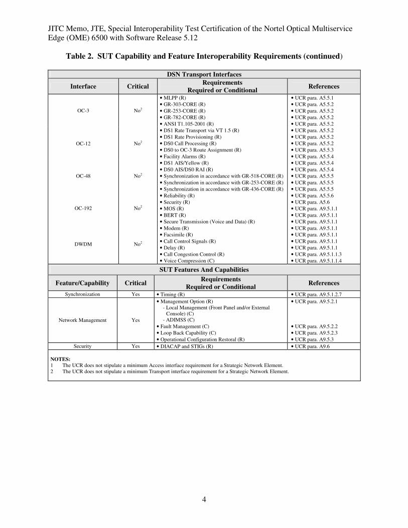
NOTES: 1 The UCR does not stipulate a minimum Access interface requirement for a Strategic Network Element.
2 The UCR does not stipulate a minimum Transport interface requirement for a Strategic Network Element.
JITC Memo, JTE, Special Interoperability Test Certification of the Nortel Optical Multiservice
Edge (OME) 6500 with Software Release 5.12
5
Table 2. SUT Capability and Feature Interoperability Requirements (continued)
LEGEND: A Appendix
ADIMSS Advanced DSN Integrated Management Support
System
AIS Alarm Indication Signal
ANSI American National Standards Institute
BERT Bit Error Rate Test
C Conditional
CAS Channel Associated Signaling
DIACAP DoD Information Assurance Certification and
Accreditation Process
DS0 Digital Signal Level 0
DS1 Digital Signal Level 1
DS3 Digital Signal Level 3 (44.736 Mbps)
DS3C Digital Signal Level 3 Concantenated (89.472
Mbps)
DSN Defense Switched Network
DSS1 Digital Subscriber Signaling 1
DWDM Dense Wavelength Division Multiplexing
E1 European Basic Multiplex Rate (2.048 Mbps)
Gbps Gigabits per second
GR Generic Requirement
GR-253-CORE SONET Transport Systems: Common Generic
Criteria
GR-303-CORE Integrated Digital Loop Carrier System Generic
Requirements, Objectives, and Interface
GR-436-CORE Digital Network Synchronization Plan
GR-518-CORE LSSGR: Synchronization, Section 18
GR-782-CORE SONET Digital Switch Trunk Interface Criteria
IP Internet Protocol
ISDN Integrated Services Digital Network
ITU-T International Telecommunication Union -
Telecommunication Standardization Sector
LSSGR Local Access and Transport Area (LATA) Switching
Systems Generic Requirements
Mbps Megabits per second
MLPP Multi-Level Precedence and Preemption
MOS Mean Opinion Score
OC-3 Optical Carrier Level 3 (155 Mbps)
OC-12 Optical Carrier Level 12 (622 Mbps)
OC-48 Optical Carrier Level 48 (2.448 Gbps)
OC-192 Optical Carrier Level 192 (10 Gbps)
para. paragraph
PRI Primary Rate Interface
Q.955.3 ISDN Signaling standard for E1 MLPP
R Required
RAI Remote Alarm Indication
SONET Synchronous Optical Network
SS7 Signaling System 7
STIGs Security Technical Implementation Guides
SUT System Under Test
T1 Digital Transmission Link Level 1 (1.544 Mbps)
T1.105-2001 SONET – Basic Description include Multiplexer
structure, rates, formats
T1.607 ISDN – Layer 3 Signaling Specification for Circuit
Switched Bearer Service for DSS1
T1.619a SS7 and ISDN MLPP Signaling Standard for T1
VT Virtual Tributary
UCR Unified Capabilities Requirements
5. No detailed test report was developed in accordance with the Program Manager’s request.
JITC distributes interoperability information via the JITC Electronic Report Distribution (ERD)
system, which uses Unclassified-But-Sensitive Internet Protocol Router Network (NIPRNet) e-
mail. More comprehensive interoperability status information is available via the JITC System
Tracking Program (STP). The STP is accessible by .mil/gov users on the NIPRNet at
https://stp.fhu.disa.mil. Test reports, lessons learned, and related testing documents and
references are on the JITC Joint Interoperability Tool (JIT) at http://jit.fhu.disa.mil (NIPRNet),
or http://199.208.204.125 (SIPRNet). Information related to DSN testing is on the Telecom
Switched Services Interoperability (TSSI) website at http://jitc.fhu.disa.mil/tssi.
6. The JITC point of contact is Capt Oskar Widecki, DSN 879-5269, commercial (520) 538-
5269, FAX DSN 879-4347, or e-mail [email protected]. The JITC’s mailing address is
P.O. Box 12798, Fort Huachuca, AZ 85670-2798. The tracking number for the SUT is
0812001.
FOR THE COMMANDER:
2 Enclosures a/s
for RICHARD A. MEADOR
Chief
Battlespace Communications Portfolio
JITC Memo, JTE, Special Interoperability Test Certification of the Nortel Optical Multiservice
Edge (OME) 6500 with Software Release 5.12
6
Distribution (electronic mail):
Joint Staff J-6
Joint Interoperability Test Command, Liaison, TE3/JT1
Office of Chief of Naval Operations, CNO N6F2
Headquarters U.S. Air Force, Office of Warfighting Integration & CIO, AF/XCIN (A6N)
Department of the Army, Office of the Secretary of the Army, DA-OSA CIO/G-6 ASA (ALT),
SAIS-IOQ
U.S. Marine Corps MARCORSYSCOM, SIAT, MJI Division I
DOT&E, Net-Centric Systems and Naval Warfare
U.S. Coast Guard, CG-64
Defense Intelligence Agency
National Security Agency, DT
Defense Information Systems Agency, TEMC
Office of Assistant Secretary of Defense (NII)/DOD CIO
U.S. Joint Forces Command, Net-Centric Integration, Communication, and Capabilities
Division, J68
Defense Information Systems Agency, GS23
Enclosure 1
ADDITIONAL REFERENCES
(c) Defense Information Systems Agency, “Department of Defense Networks Unified
Capabilities Requirements,” 21 December 2007
(d) Joint Interoperability Test Command, “Defense Switched Network Generic Switch Test
Plan (GSTP), Change 2,” 2 October 2006
(e) Joint Interoperability Test Command, “Information Assurance (IA) Assessment of Nortel
Optical Multiservice Edge (OME) 6500 Release 5.12 Information Assurance (Tracking
Number 0812001),” 10 March 2009
Enclosure 2
CERTIFICATION TESTING SUMMARY
1. SYSTEM TITLE. Nortel Optical Multiservice Edge (OME) 6500 with Software Release 5.12, hereinafter referred to as the System Under Test (SUT).
2. PROPONENTS. Air Mobility Command (AMC). 3. PROGRAM MANAGER. Ms. Mary Stovey, AMC, A6NI, 203 W Loset St., Scott Air Force Base, Illinois, 62225, e-mail: [email protected]. 4. TESTER. Joint Interoperability Test Command (JITC), Fort Huachuca, Arizona. 5. SYSTEM UNDER TEST DESCRIPTION. The SUT combines and extends Synchronous Optical Network (SONET)/Synchronous Digital Hierarchy (SDH) and metropolitan Dense Wavelength Division Multiplexing (DWDM) platforms for converged time division multiplexing (TDM), data, wavelength, and transparent services transport over a single consolidated multi-service optical platform. The optical networking platforms are capable of efficiently aggregating, switching, and managing a mix of global services ranging from the lower speed Digital Signal Level 1 (DS1), European Basic Multiplex Rate (E1), and Digital Signal Level 3 (DS3) electrical interfaces and the higher speed Optical Carrier Level 3 (OC-3), Optical Carrier Level 12 (OC-12), Optical Carrier Level 48 (OC-48), Optical Carrier Level 192 (OC-192) interfaces, 1 Gbps Ethernet, 10 Gbps Ethernet and 40 Gbps DWDM channels. Optical Carrier Level 48 (OC-48), and Optical Carrier Level 192 (OC-192) interfaces. The SUT is a global platform that can be deployed in both SONET and SDH environments. The SONET and SDH protocols are supported on the same circuit pack and can be provisioned by the user. The SUT also supports a 10 Gigabits per second (Gbps) Resilient Packet Ring (RPR), which is a ring based technology that enables bandwidth sharing across multiple 1 Gbps Ethernet ports. The SUT provides common transport for TDM and data interfaces to support voice transport. The SUT provides Voice and VoIP transport over DWDM interfaces at 2.5Gbps, 10Gbps and 40Gbps. The OME 6500 is capable of supporting SONET, SDH, Data and Wavelength DWDM services from a single shelf. The SUT uses optical amplifiers and ROADMs to support a total of 44 DWDM channels; with each DWDM channel capable of 2.5Gbps, 10Gbps and 40Gbps transport. Deployed in a ring transport topology, the SUT has a main shelf that has an Internet Protocol (IP) connection supporting Secure Shell (SSH). This IP connection will allow a base to have each user first authenticate with a Remote Authentication Dial In User Service (RADIUS) server. After successful authentication, the user can then access the SUT network and perform assigned duties. Remote locations are visible from the secure SSH IP connection of the main shelf. At remote shelves, all access ports are turned off denying anyone access to the network. Each OME 6500 remote shelf will be contained in a protected enclave preventing unauthorized access to the site. This, in turn, prevents unauthorized personnel from attempting to access remote shelves. The
2-2
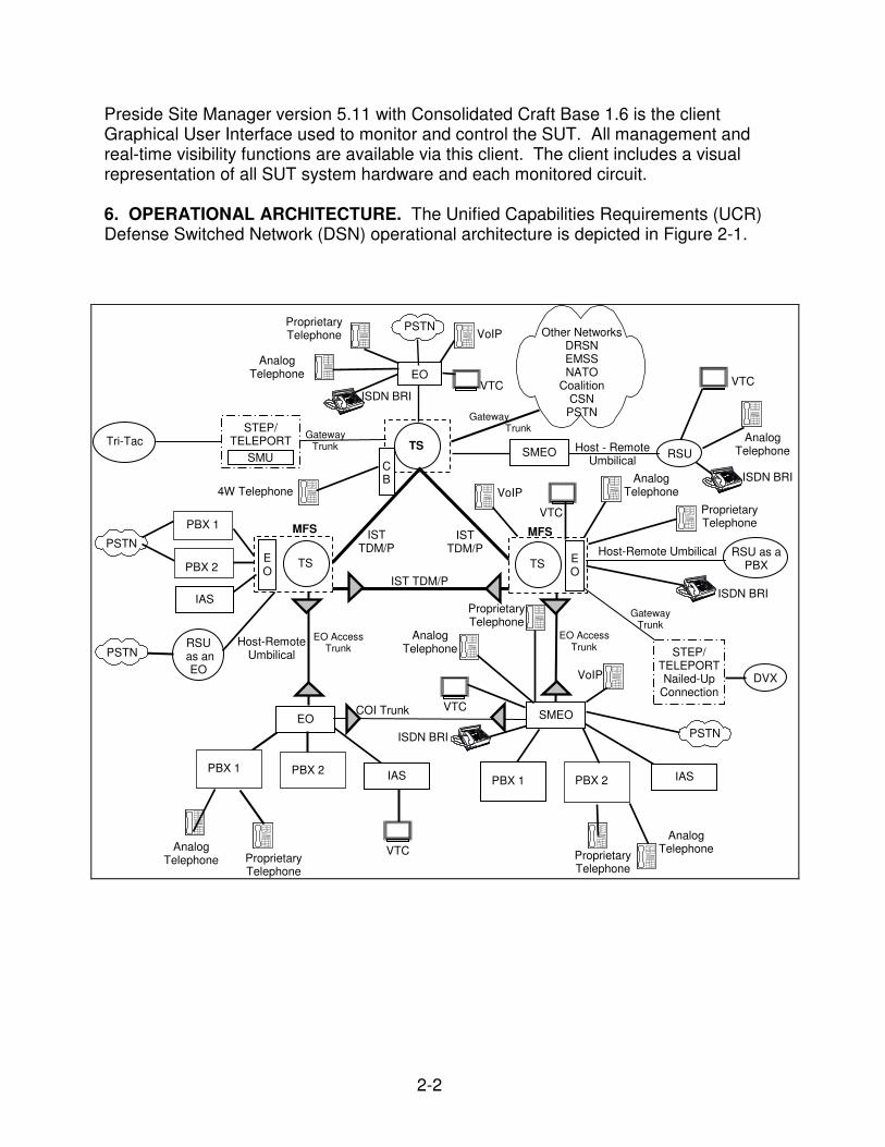
Preside Site Manager version 5.11 with Consolidated Craft Base 1.6 is the client Graphical User Interface used to monitor and control the SUT. All management and real-time visibility functions are available via this client. The client includes a visual representation of all SUT system hardware and each monitored circuit. 6. OPERATIONAL ARCHITECTURE. The Unified Capabilities Requirements (UCR) Defense Switched Network (DSN) operational architecture is depicted in Figure 2-1.
EO
TS
EO
SMEO RSU
RSU as an
EO
E O
MFS IST
TDM/P IST
TDM/P
IST TDM/P
RSU as a PBX
Tri-Tac
SMEO
STEP/ TELEPORT Nailed-Up
Connection DVX
Host - Remote Umbilical
MFS
COI Trunk
STEP/ TELEPORT
Gateway Trunk
SMU
TS TS E O
EO Access Trunk
Gateway Trunk
PSTN
Telephone Telephone
PBX 1
PBX 2
IAS
Analog Telephone Proprietary
Telephone
PBX 1
PBX 2
IAS
PSTN
VTC
Analog Telephone
Proprietary Telephone
Telephone Telephone ISDN BRI
VTC
VoIP
Analog Telephone
Proprietary Telephone
EO Access Trunk
Telephone Telephone ISDN BRI
Host-Remote Umbilical
Proprietary Telephone
Analog Telephone VoIP
VTC
Telephone Telephone
Other Networks DRSN EMSS NATO
Coalition CSN
PSTN
VTC
Analog Telephone
ISDN BRI
Gateway Trunk
VTC
VoIP Proprietary Telephone
Analog Telephone
ISDN BRI
C B
4W Telephone
PBX 1
PBX 2
IAS
PSTN Host-Remote
Umbilical
PSTN
2-3
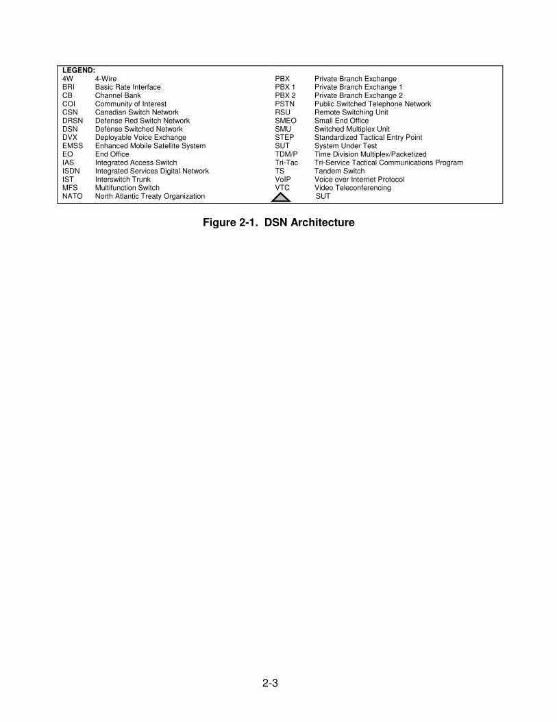
LEGEND: 4W 4-Wire BRI Basic Rate Interface CB Channel Bank COI Community of Interest CSN Canadian Switch Network DRSN Defense Red Switch Network DSN Defense Switched Network DVX Deployable Voice Exchange EMSS Enhanced Mobile Satellite System EO End Office IAS Integrated Access Switch ISDN Integrated Services Digital Network IST Interswitch Trunk MFS Multifunction Switch NATO North Atlantic Treaty Organization
PBX Private Branch Exchange PBX 1 Private Branch Exchange 1 PBX 2 Private Branch Exchange 2 PSTN Public Switched Telephone Network RSU Remote Switching Unit SMEO Small End Office SMU Switched Multiplex Unit STEP Standardized Tactical Entry Point SUT System Under Test TDM/P Time Division Multiplex/Packetized Tri-Tac Tri-Service Tactical Communications Program TS Tandem Switch VoIP Voice over Internet Protocol VTC Video Teleconferencing
SUT
Figure 2-1. DSN Architecture
2-4
7. REQUIRED SYSTEM INTERFACES. The SUT Interoperability Test Summary is shown in Table 2-1 and the Capability and Feature Requirements used to evaluate the interoperability of the SUT are indicated in Table 2-2. These requirements are derived from the UCR and verified through JITC testing and review of vendor Letters of Compliance (LoC).
Table 2-1. SUT Interoperability Test Summary
DSN Access Interfaces
DSN Switch Access Critical Status Remarks
T1 CAS (AMI/SF) DTMF, MFR1, DP No1 Certified Met all CRs and FRs.
T1 CAS (B8ZS/ESF) DTMF, MFR1, DP No1 Certified Met all CRs and FRs.
T1 PRI (ANSI T1.619a) No1 Certified Met all CRs and FRs.
T1 SS7 (ANSI T1.619a) No1 Certified Met all CRs and FRs.
E1 CAS (HDB3) DTMF, MFR1, DP No
1
(Europe only) Not Tested
E1 CAS is supported by the SUT; however it was not tested. The SUT E1 CAS interface is therefore not certified by JITC, or
authorized for use by the DSN PMO for use within the DSN. This is not a required interface for a Strategic Network Element.
E1 ISDN PRI (ITU-T Q.955.3)
No1
(Europe only) Not Tested
E1 ISDN PRI is supported by the SUT; however it was not tested. The SUT E1 ISDN PRI interface is therefore not certified
by JITC, or authorized for use by the DSN PMO for use within the DSN. This is not a required interface for a Strategic Network
Element.
E1 SS7 (ANSI T1.619a) No
1
(Europe only) Not Tested
E1 SS7 is supported by the SUT; however it was not tested. The SUT E1 SS7 interface is therefore not certified by JITC, or
authorized for use by the DSN PMO for use within the DSN. This is not a required interface for a Strategic Network Element.
DS3 No1 Certified Met all CRs and FRs.
DS3C No1 Certified Met all CRs and FRs.
Gigabit Ethernet No1 Certified Met all CRs and FRs.
2
10 Gigabit Ethernet No1 Certified Met all CRs and FRs.
2
DSN Transport Interfaces
Optical Carrier Level
Transport Level
Critical Status Remarks
VT 1.5 No3 Certified Met all CRs and FRs.
OC-3 STS-1 No
3 Certified Met all CRs and FRs. VT 1.5 No
3 Certified Met all CRs and FRs.
OC-12 STS-1 No
3 Certified Met all CRs and FRs.
VT 1.5 No3 Certified Met all CRs and FRs.
OC-48 STS-1 No
3 Certified Met all CRs and FRs.
VT 1.5 No3 Certified Met all CRs and FRs.
OC-192 STS-1 No
3 Certified Met all CRs and FRs.
DWDM 2.5, 10 and 40
Gigabit Channels No
3 Certified Met all CRs and FRs.
Features And Capabilities
Features and Capabilities Critical Status Remarks
Synchronization Yes Certified Met all CRs and FRs.
Network Management Yes Certified Met all CRs and FRs.
Security Yes Certified See note 4. NOTES: 1 The UCR does not stipulate a minimum Access interface requirement for a Strategic Network Element. 2 The SUT 1 and 10 Gbps Ethernet interfaces were tested and certified for voice only as an extension to an ASLAN on the UC APL. 3 The UCR does not stipulate a minimum Transport interface requirement for a Strategic Network Element. 4 Information assurance testing is accomplished via DISA-led Information Assurance test teams and published in a separate report,
reference (e).
2-5
Table 2-1. SUT Interoperability Test Summary (continued) LEGEND: AMI Alternate Mark Inversion ANSI American National Standards Institute APL Approved Products List ASLAN Assured Services Local Area Network B8ZS Bipolar Eight Zero Substitution CAS Channel Associated Signaling CR Capability Requirements DISA Defense Information Systems Agency DP Dial Pulse DS3 Digital Signal Level 3 (44.736 Mbps) DS3C Digital Signal Level 3 (89.472 Mbps) DSN Defense Switched Network DTMF Dual Tone Multi-Frequency DWDM Dense Wavelength Division Multiplexing E1 European Basic Multiplex Rate (2.048 Mbps) ESF Extended Super Frame FR Feature Requirements Gbps Gigabits per second HDB3 High Density Bipolar 3 ISDN Integrated Services Digital Network
ITU-T International Telecommunication Union –
Telecommunication Standardization Mbps Megabits per second MFR1 Multi-frequency Recommendation 1 MLPP Multi-Level Precedence and Preemption OC-3 Optical Carrier Level 3 (155 Mbps) OC-12 Optical Carrier Level 12 (622 Mbps) OC-48 Optical Carrier Level 48 (2.448 Gbps) OC-192 Optical Carrier Level 192 (10 Gbps) PRI Primary Rate Interface Q.955.3 ISDN Signaling Standard for E1 MLPP SF Super Frame SS7 Signaling System 7 SUT System Under Test STS Synchronous Transport Signal T1 Digital Transmission Link Level 1 (1.544 Mbps) T1.619a SS7 and ISDN MLPP Signaling Standard for T1 UC Unified Capabilities UCR Unified Capabilities Requirements VT Virtual Tributary
Table 2-2. SUT Capability and Feature Interoperability Requirements
NOTES: 1 The UCR does not stipulate a minimum Access interface requirement for a Strategic Network Element. 2 The UCR does not stipulate a minimum Transport interface requirement for a Strategic Network Element.
2-7
Table 2-2. SUT Capability and Feature Interoperability Requirements (continued) LEGEND: A Appendix ADIMSS Advanced DSN Integrated Management
Support System AIS Alarm Indication Signal ANSI American National Standards Institute BERT Bit Error Rate Test C Conditional CAS Channel Associated Signaling DIACAP DoD Information Assurance Certification and
Accreditation Process DS0 Digital Signal Level 0 DS1 Digital Signal Level 1 DS3 Digital Signal Level 3 (44.736 Mbps) DS3C Digital Signal Level 3 Concantenated (89.472
Mbps) DSN Defense Switched Network DSS1 Digital Subscriber Signaling 1 DWDM Dense Wavelength Division Multiplexing E1 European Basic Multiplex Rate (2.048 Mbps) Gbps Gigabits per second GR Generic Requirement GR-253-CORE SONET Transport Systems: Common Generic
Criteria GR-303-CORE Integrated Digital Loop Carrier System Generic
Requirements, Objectives, and Interface GR-436-CORE Digital Network Synchronization Plan GR-518-CORE LSSGR: Synchronization, Section 18 GR-782-CORE SONET Digital Switch Trunk Interface Criteria IP Internet Protocol
ISDN Integrated Services Digital Network ITU-T International Telecommunication Union -
Telecommunication Standardization Sector LSSGR Local Access and Transport Area (LATA)
Switching Systems Generic Requirements Mbps Megabits per second MLPP Multi-Level Precedence and Preemption MOS Mean Opinion Score OC-3 Optical Carrier Level 3 (155 Mbps) OC-12 Optical Carrier Level 12 (622 Mbps) OC-48 Optical Carrier Level 48 (2.448 Gbps) OC-192 Optical Carrier Level 192 (10 Gbps) para. paragraph PRI Primary Rate Interface Q.955.3 ISDN Signaling standard for E1 MLPP R Required RAI Remote Alarm Indication SONET Synchronous Optical Network SS7 Signaling System 7 STIGs Security Technical Implementation Guides SUT System Under Test T1 Digital Transmission Link Level 1 (1.544 Mbps) T1.105-2001 SONET – Basic Description include Multiplexer
Switched Bearer Service for DSS1 T1.619a SS7 and ISDN MLPP Signaling Standard for T1 VT Virtual Tributary UCR Unified Capabilities Requirements
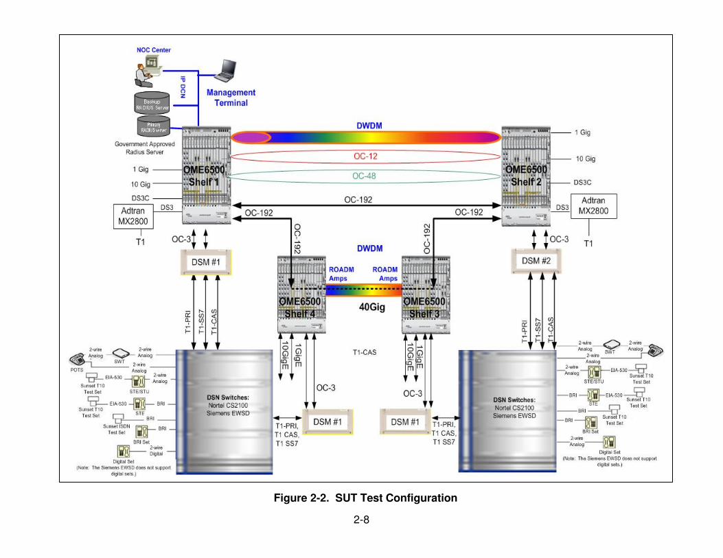
8. TEST NETWORK DESCRIPTION. The SUT was tested at JITC’s Global Information Grid Network Test Facility in a manner and configuration similar to that of the DSN operational environment. This test was conducted using the test configuration shown in Figure 2-2.
2-8
Figure 2-2. SUT Test Configuration
2-9
IP Internet Protocol Mbps Megabits per second MX Multiplexer NOC Network Operations Center OC-3 Optical Carrier Level 3 (155 Mbps) OC-12 Optical Carrier Level 12 (622 Mbps) OC-48 Optical Carrier Level 48 (2.448 Gbps) OC-192 Optical Carrier Level 192 (10 Gbps) OME Optical Multiservice Edge PRI Primary Rate Interface RADIUS Remote Authentication Dial In User Service ROADM Reconfigurable optical add drop multiplexer SS7 Signaling System 7 STE Secure Terminal Equipment STU Secure Telephone Unit SUT System Under Test SWT Secure Wireline Terminal T1 Digital Transmission Link Level 1 (1.544 Mbps)
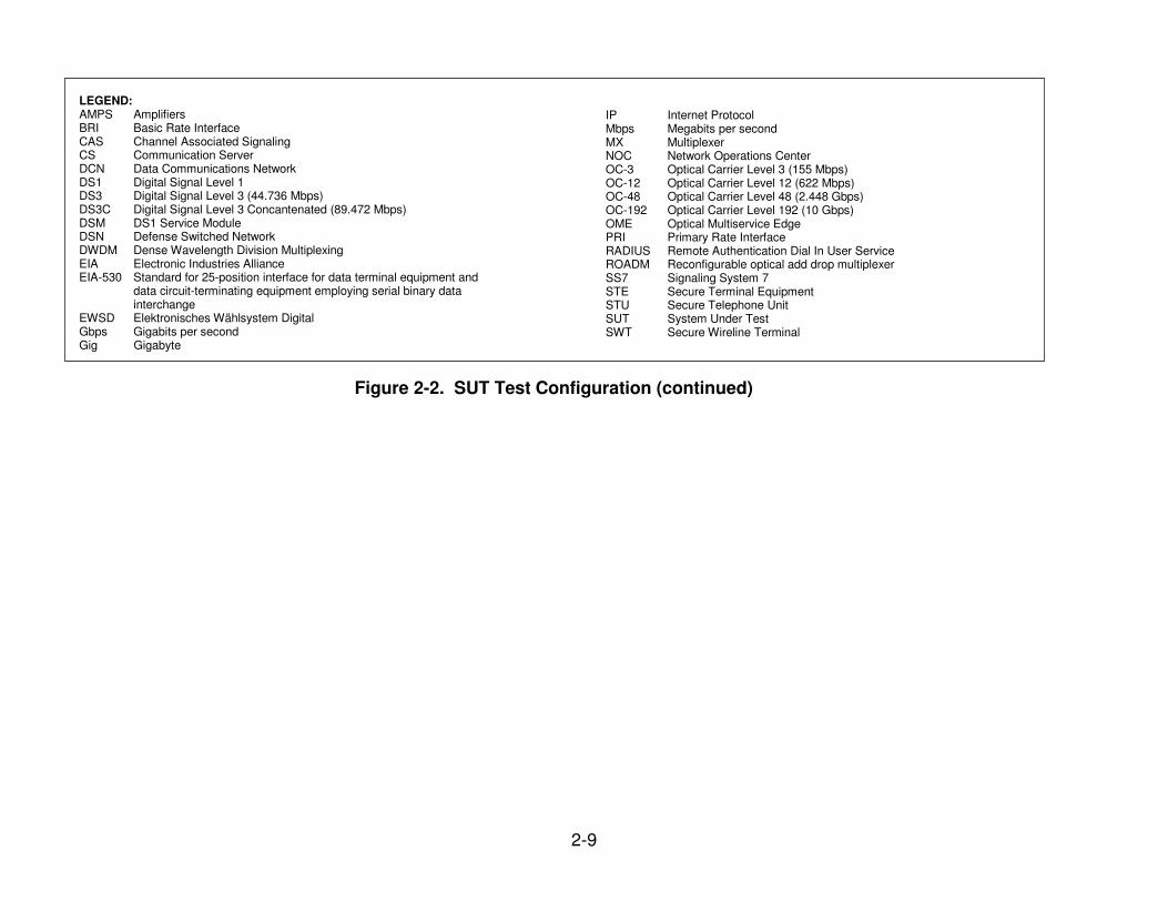
Figure 2-2. SUT Test Configuration (continued)
LEGEND: AMPS Amplifiers BRI Basic Rate Interface CAS Channel Associated Signaling CS Communication Server DCN Data Communications Network DS1 Digital Signal Level 1 DS3 Digital Signal Level 3 (44.736 Mbps) DS3C Digital Signal Level 3 Concantenated (89.472 Mbps) DSM DS1 Service Module DSN Defense Switched Network DWDM Dense Wavelength Division Multiplexing EIA Electronic Industries Alliance EIA-530 Standard for 25-position interface for data terminal equipment and
data circuit-terminating equipment employing serial binary data interchange
EWSD Elektronisches Wählsystem Digital Gbps Gigabits per second Gig Gigabyte
2-10
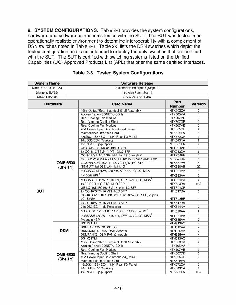
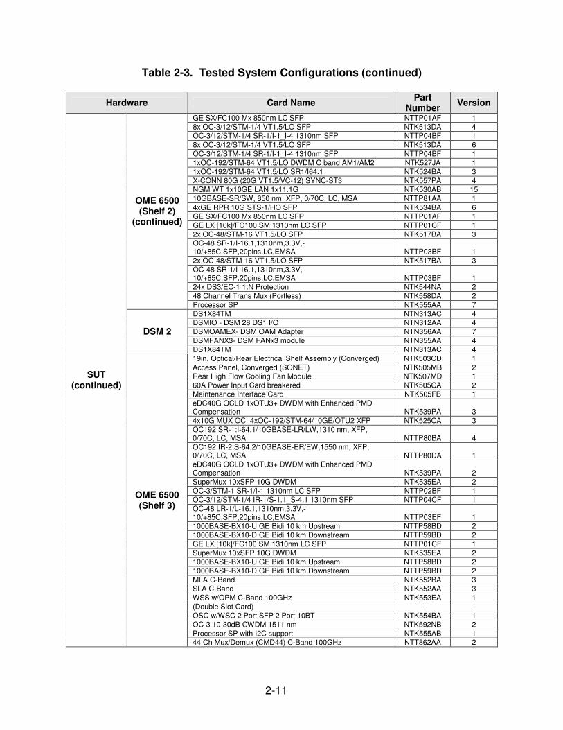
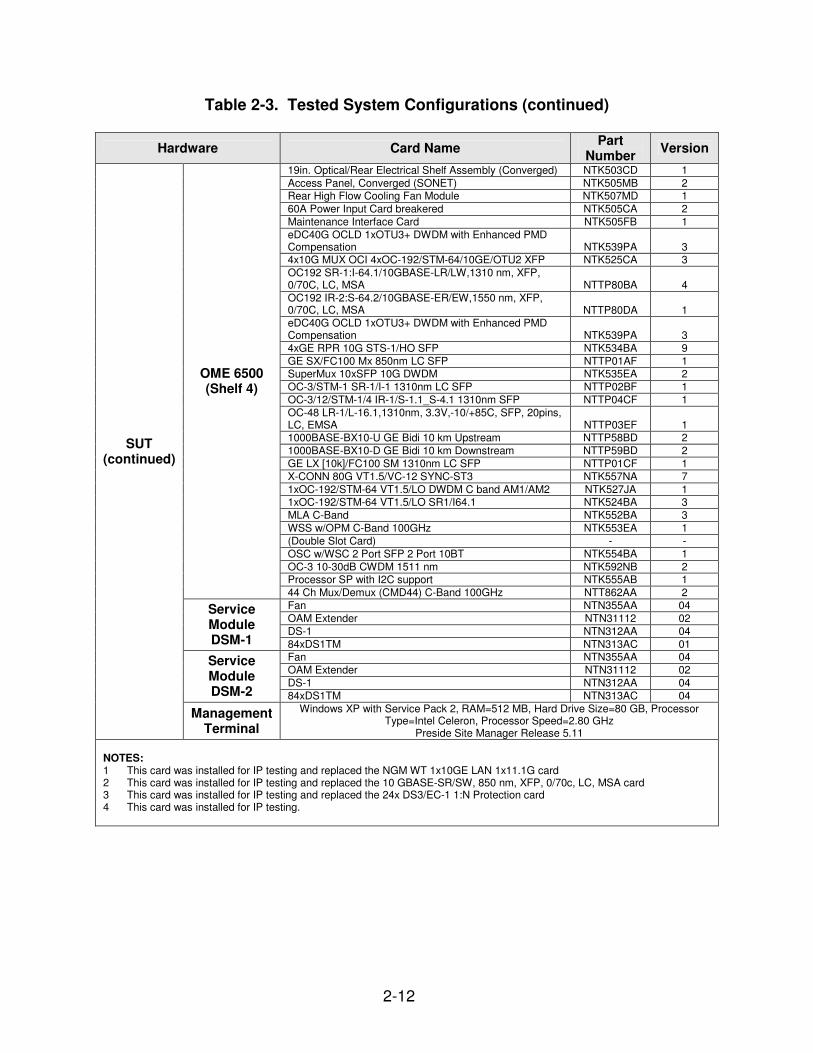
9. SYSTEM CONFIGURATIONS. Table 2-3 provides the system configurations, hardware, and software components tested with the SUT. The SUT was tested in an operationally realistic environment to determine interoperability with a complement of DSN switches noted in Table 2-3. Table 2-3 lists the DSN switches which depict the tested configuration and is not intended to identify the only switches that are certified with the SUT. The SUT is certified with switching systems listed on the Unified Capabilities (UC) Approved Products List (APL) that offer the same certified interfaces.
OC-48 LR-1/L-16.1,1310nm, 3.3V,-10/+85C, SFP, 20pins, LC, EMSA NTTP03EF 1 1000BASE-BX10-U GE Bidi 10 km Upstream NTTP58BD 2
1000BASE-BX10-D GE Bidi 10 km Downstream NTTP59BD 2
GE LX [10k]/FC100 SM 1310nm LC SFP NTTP01CF 1
X-CONN 80G VT1.5/VC-12 SYNC-ST3 NTK557NA 7
1xOC-192/STM-64 VT1.5/LO DWDM C band AM1/AM2 NTK527JA 1 1xOC-192/STM-64 VT1.5/LO SR1/I64.1 NTK524BA 3
MLA C-Band NTK552BA 3
WSS w/OPM C-Band 100GHz NTK553EA 1
(Double Slot Card) - -
OSC w/WSC 2 Port SFP 2 Port 10BT NTK554BA 1
OC-3 10-30dB CWDM 1511 nm NTK592NB 2 Processor SP with I2C support NTK555AB 1
OME 6500 (Shelf 4)
44 Ch Mux/Demux (CMD44) C-Band 100GHz NTT862AA 2
Fan NTN355AA 04
OAM Extender NTN31112 02
DS-1 NTN312AA 04
Service Module DSM-1 84xDS1TM NTN313AC 01
Fan NTN355AA 04
OAM Extender NTN31112 02
DS-1 NTN312AA 04
Service Module DSM-2 84xDS1TM NTN313AC 04
SUT (continued)
Management Terminal
Windows XP with Service Pack 2, RAM=512 MB, Hard Drive Size=80 GB, Processor Type=Intel Celeron, Processor Speed=2.80 GHz
Preside Site Manager Release 5.11 NOTES: 1 This card was installed for IP testing and replaced the NGM WT 1x10GE LAN 1x11.1G card 2 This card was installed for IP testing and replaced the 10 GBASE-SR/SW, 850 nm, XFP, 0/70c, LC, MSA card 3 This card was installed for IP testing and replaced the 24x DS3/EC-1 1:N Protection card 4 This card was installed for IP testing.
2-13
Table 2-3. Tested System Configurations (continued)
LEGEND: 5ESS Class 5 Electronic Switching System CCA Compact Call Agent CS Communication Server DS-1 Digital Signal Level 1 DS1 Digital Signal Level 1 DS3 Digital Signal Level 3 DSM DS1 Service Module DWDM Dense Wavelength Division Multiplexing EC Electrical Carrier EC1 Electrical Carrier Level 1 EPL Ethernet Private Line EWSD Elektronisches Wählsystem Digital G.709 ITU-T Recommendation for Interfaces for the
Optical Transport Network (OTN) G Gigabit GB Gigabyte Gbps Gigabits per second GE Gigabit Ethernet GHz Gigahertz HO High Order ITU-T International Telecommunication Union -
Telecommunication Standardization Sector LAN Local Area Network LO Low Order MB Megabyte Mbps Megabits per second NGM Next Generation Modem NTK Nortel Networks NTN Nortel Networks
OAM Operations, Administration, and Maintenance OC Optical Carrier OC-3 Optical Carrier Level 3 (155 Mbps) OC-12 Optical Carrier Level 12 (622 Mbps) OC-48 Optical Carrier Level 48 (2.488 Gbps) OC-192 Optical Carrier Level 192 (10 Gbps) OME Optical Multi-service Edge R Release RAM Random Access Memory RPR Resilient Packet Ring SFP Small Form Factor Pluggable SP Shelf Processor STM Synchronous Transport Module STM-1/4 Synchronous Transport Mode ¼ (38.88 Mbps) STM-16 Synchronous Transport Mode 16 (2488.32
Mbps) STM-64 Synchronous Transport Mode 64 (9953.28
Mbps) STS Synchronous Transport Signal Sync-ST3 Synchronous Traceable Stratum 3 (Accuracy
4.6 x 10⁻⁶)
TM Terminal Multiplexer VC-12 Virtual Containers 12 (2.048 Mbps) VT1.5 Virtual Tributary 1.5 WAN Wide Area Network WT Wavelength Translators X-Conn Cross Connect XFP 10 Gigabit Small Form Factor Pluggable Module XP Experience
10. TEST LIMITATIONS. None. 11. TEST RESULTS a. Discussion (1) DSN Access Interfaces. The SUT supports both DS1 and DS3 interfaces. Channel Associated Signaling (CAS) and Common Channel Signaling trunks were provisioned and tested. All trunk types were provisioned and tested on the DSM and Adtran 2800 M13 Multiplexer. In addition, the SUT supports Gigabit and 10 Gigabit Ethernet interfaces. All of the interface types were mapped through the test network via Virtual Tributary (VT)1.5 and Synchronous Transport Signal (STS)-1 transport levels over all of the supported SONET interfaces described in paragraph (5). The gigabit SuperMux access interface (Part Number: NTK535EA) does not support auto-negotiation. Although the SUT offers E1 access interfaces, these interfaces were not tested by JITC and are not authorized for use within the DSN by the DSN Program Management Office (PMO). The specific requirements and test results of the DSN Access Interface testing are described below. (a) Interface Characteristics. The DS1 and DS3 interface characteristics were tested in accordance with UCR, Appendix 9, paragraphs A9.5.1.2.4 and A9.5.1.2.6. The DS1 interface supports both Alternate Mark Inversion (AMI) and Bipolar
2-14
Eight Zero Substitution (B8ZS) line coding. The DS3 interface supports Bipolar Three Zero Substitution (B3ZS) line coding. The DS3 interface supports both C-bit and M13 framing. All Access interface characteristics were verified through both vendor LoC and testing. (b) Supervisory Channel Associated Signaling. Trunk seizure, answer supervision, preemption signals, and all other trunk supervisory information sent and received on a per channel basis was passed transparently through the SUT as required in the UCR, appendix 9. (c) Clear Channel Capability. The SUT is capable of transmitting and receiving B8ZS line coding in accordance with UCR, appendix 9. (d) Mean Opinion Score (MOS). The UCR, appendix 9, paragraph A9.5.1.1, states that the introduction of network element(s) (NEs) shall not cause the end-to-end average MOS to fall below 4.0 as measured over any five-minute time interval. The Abacus call loader was used to generate voice traffic across the DS1 links mapped through the SUT test network as depicted in Figure 2-2. There were 107,926 calls placed over the DS1 interfaces, with all calls placed via the SUT having a MOS of at least 4.0. The IXIA data loader was also used to generate voice traffic over the 1Gbps Ethernet Private Line (EPL), 10Gbps EPL and 1Gbps RPR mapped through the SONET test network. The IXIA voice traffic had a minimum MOS of 4.37 with an average MOS of 4.6, which meets the requirement. (e) Bit Error Rate Test (BERT). The UCR, appendix 9, paragraph A9.5.1.1, states that the introduction of an NE shall exceed the end-to-end digital bit error rate requirement of less than 1 error in 1x10⁹ (averaged over a nine-hour period). BERTs were conducted across DS1 and DS3 interfaces. The SUT met this requirement for all interfaces with an end-to-end bit error rate of less than one error in 1x10⁻⁹
averaged over a nine-hour period, which meets the requirement. (f) Secure Transmission (Voice and Data). The UCR, appendix 9, paragraph A9.5.1.1, states that the introduction of NE(s) shall not degrade secure transmission for secure end devices as defined by UCR, appendix 10. There were 284 secure calls placed between Secure Terminal Equipment (STEs) and Secure Wireline Terminals (SWTs) without degrading transmissions between end devices, which meets the requirement. (g) Modem. The UCR, appendix 9, paragraph A9.5.1.1, states that the NE(s) shall support a minimum modem transmission speed of 9.6 kilobits per second (kbps) across the associated NE(s). There were 29,894 modem calls placed through the SUT using the Abacus call loader. All modem calls had a transmission rate of 23.7 kbps, which meets the requirement. (h) Facsimile. The UCR, appendix 9, paragraph A9.5.1.1, states that the NE(s) shall support a minimum facsimile transmission speed of 9.6 kbps across the
2-15
associated NE(s). There were 44,494 facsimile calls placed through the SUT using the Abacus call loader. All facsimile calls had a transmission rate of 14.4 kbps, which meets the requirement. (i) Call Control Signals. The UCR, appendix 9, paragraph A9.5.1.1, states that the NE shall transport all call control signals transparently on an end-to-end basis. The SUT transparently transported all Multi-level Precedence and Preemption (MLPP) call control signals, which meets the requirement. (j) Delay. Delay occurs when packets take more time than expected to reach their destination. The UCR, appendix 9, paragraph A9.5.1.1, states that the addition of S-NEs shall not cause the one-way delay measured from ingress to egress to increase by more than 5 milliseconds (ms) for each S-NE used, averaged over any five-minute period. The average one-way delay for each of the sampled five-minute periods, measured between NE devices, was 1 ms, which meets the requirement. (k) Alarm and Restoral Requirements. The UCR, appendix 9, paragraph A9.5.1.1.1, states that the NE shall be able to propagate Carrier Group Alarms (CGAs) in accordance with UCR, section 7, upon physical loss of the TDM interface. Voice switching systems shall receive the proper CGAs from the NE upon loss of the transport link between NEs, regardless of whether it is TDM or IP. The SUT is capable of transparently passing the alarm and restoral features of the DSN switch’s digital interface unit, which meets the requirement. (l) Call Congestion. The UCR, appendix 9, paragraph A9.5.1.1.2, states that the NE shall assure that congestion between NEs does not impact DSN calls in progress or subsequent calls. Call congestion handling shall be met in one or more of the following three ways: dynamic load control signal; software capability which makes congestion impossible; or congestion is not possible in the SUT. Call congestion in the SUT is not possible, which meets the requirement.
(m) Voice Compression. UCR appendix 9, paragraph A9.5.1.1.4, states that the NE may include voice compression and if so must support at least one of the following standards:
• International Telecommunication Union - Telecommunication Standardization Sector (ITU-T) Recommendation G.726, 32 kbps Adaptive Differential Pulse Code Modulation (ADPCM) • ITU-T Recommendation G.728, 16 kbps Low-Delay Code Excited Linear Prediction (LD-CELP) • ITU-T Recommendation G.729, 9.6 kbps Conjugate-Structure Algebraic-Code-Excited Linear-Prediction (CS-A CELP) Voice compression is not a feature provided by the SUT. This requirement is conditional and has no operational impact on network interoperability.
2-16
(n) Internet Protocol (IP) interface. The UCR, appendix 9, paragraph A9.5.1.2.9, states that S-NEs using IP shall meet all of the following requirements in the subparagraphs below. All IP interface characteristics were verified through both vendor LoC and testing. 1. Delay. Delay occurs when packets take more time than expected to reach their destination. The UCR, appendix 9, paragraph A9.5.1.2.9, states that the addition of S-NEs shall not increase the one-way packet delay for each S-NE used, when measured from ingress to egress and averaged over any five-minute period more than that which is specified under the following conditions: a. TDM Ingress to Non-Transcoding Packet Egress shall not increase delay by more than a maximum total delay of 50 ms as measured from end-to-end as a pair. b. TDM Ingress to Transcoding Packet Egress shall not increase delay by more than a maximum total delay of 100 ms as measured from end-to-end as a pair. There were IXIA VoIP pairs generated through the SUT using the Ixia. The average one-way delay for each of the sampled five-minute periods, measured between NE devices, was 1 ms, which meets the requirement. 2. Jitter. Jitter occurs when packets are sent and received with timing variations. The UCR, appendix 9, paragraph A9.5.1.2.9, states the addition of S-NE shall not cause jitter measured from ingress to egress to increase by more than five ms averaged over any five-minute period. The Ixia test set was used to generate traffic and measure jitter. With a bandwidth load, jitter was measured to be 0 ms over a five-minute period, which meets the requirement. 3. Packet Loss. Packet loss occurs when packets are sent, but not received at the final destination. The UCR, appendix 9, paragraph A9.5.1.2.9, states that the addition of an S-NE shall not cause packet loss measured from ingress to egress to increase by more than 0.05 percent averaged over any five-minute period. The Ixia test set was used to generate traffic and measure delay. With bandwidth load, the measured packet loss was 0.00 percent over a five minute period, which meets the requirement. (2) DSN Transport Interfaces. The SUT supports SONET standard optical carrier link levels of OC-3, OC-12, OC-48, OC-192 and DWDM interfaces of 2.5 Gbps, 10 Gbps and 40 Gbps. The SONET and DWDM interfaces were tested in accordance with the UCR, appendix 5. The optical carrier links were tested in a direct-connect configuration and a fully redundant ring configuration. The SUT’s SONET interfaces supported switching at the VT1.5 and STS-1 transport levels. The SUT, when configured at maximum capacity, provides for 44- channel DWDM each separated by 100 GHz for a rate of 2.5 Gbps, 10 Gbps and 40 Gbps per channel.
2-17
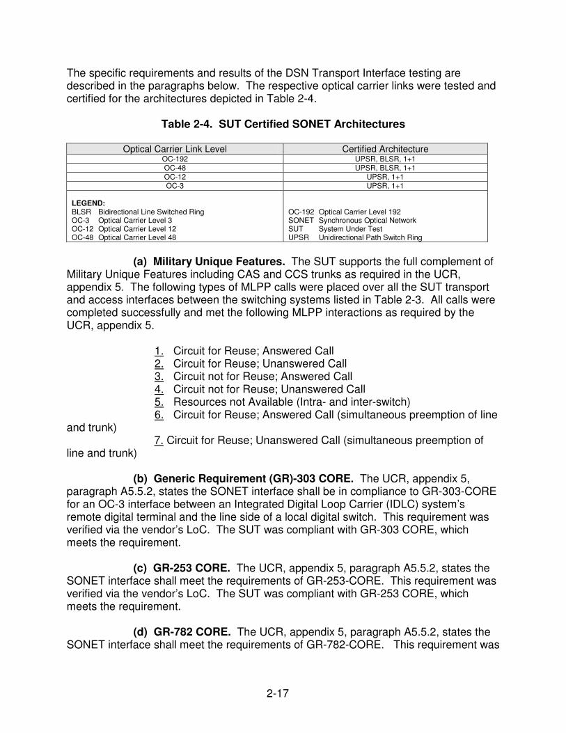
The specific requirements and results of the DSN Transport Interface testing are described in the paragraphs below. The respective optical carrier links were tested and certified for the architectures depicted in Table 2-4.
Table 2-4. SUT Certified SONET Architectures
Optical Carrier Link Level Certified Architecture OC-192 UPSR, BLSR, 1+1
OC-192 Optical Carrier Level 192 SONET Synchronous Optical Network SUT System Under Test UPSR Unidirectional Path Switch Ring
(a) Military Unique Features. The SUT supports the full complement of Military Unique Features including CAS and CCS trunks as required in the UCR, appendix 5. The following types of MLPP calls were placed over all the SUT transport and access interfaces between the switching systems listed in Table 2-3. All calls were completed successfully and met the following MLPP interactions as required by the UCR, appendix 5.
1. Circuit for Reuse; Answered Call 2. Circuit for Reuse; Unanswered Call 3. Circuit not for Reuse; Answered Call 4. Circuit not for Reuse; Unanswered Call 5. Resources not Available (Intra- and inter-switch) 6. Circuit for Reuse; Answered Call (simultaneous preemption of line
and trunk) 7. Circuit for Reuse; Unanswered Call (simultaneous preemption of line and trunk) (b) Generic Requirement (GR)-303 CORE. The UCR, appendix 5, paragraph A5.5.2, states the SONET interface shall be in compliance to GR-303-CORE for an OC-3 interface between an Integrated Digital Loop Carrier (IDLC) system’s remote digital terminal and the line side of a local digital switch. This requirement was verified via the vendor’s LoC. The SUT was compliant with GR-303 CORE, which meets the requirement. (c) GR-253 CORE. The UCR, appendix 5, paragraph A5.5.2, states the SONET interface shall meet the requirements of GR-253-CORE. This requirement was verified via the vendor’s LoC. The SUT was compliant with GR-253 CORE, which meets the requirement. (d) GR-782 CORE. The UCR, appendix 5, paragraph A5.5.2, states the SONET interface shall meet the requirements of GR-782-CORE. This requirement was
2-18
verified via the vendor’s LoC. The SUT was compliant with GR-782 CORE, which meets the requirement. (e) American National Standards Intitute (ANSI) T1.105-2001. The UCR, appendix 5, paragraph A5.5.2, states the SONET digital trunk interface shall, as a minimum, comply to ANSI T1.105-2001, “Synchronous Optical Network (SONET) - Basic Description including Multiplex Structure, Rates, and Formats ”. This requirement was verified via testing and the vendor’s LoC. The SUT was compliant with ANSI T1.105-2001, which meets the requirement.
(f) DS1 Rate Transport via VT1.5. The UCR, appendix 5, paragraph A5.5.2, states all features and functions that are defined in the UCR 2007 to operate at a DS1 rate shall work transparently at the VT1.5 rate over the SONET interface. This requirement was verified via testing and the vendor’s LoC. All features and functions that are defined to operate at the DS1 rate worked transparently at the VT1.5 rate over the SUTs SONET interfaces, which meets the requirement. (g) DS1 Rate Provisioning. The UCR, appendix 5, paragraph A5.5.2, states the SONET digital interface shall support provisioning of transport levels as low as the DS1 rate for separately grouping of various categories of traffic such as voice, data, satellite, and terrestrial transmission. This requirement was verified via testing and the vendor’s LoC. The SUT supports the provisioning of transport levels as low as the DS1 rate, which meets the requirement. (h) DS0 to OC-3 Route Assignment. The UCR, appendix 5, paragraph A5.5.3, states the SONET digital trunk interface shall support “ROUTE” assignment of trunk group(s) at the OC-3 (highest) and down to DS0 (lowest) rates as defined in UCR Section 4.2 and shall support the signaling requirements as defined in UCR Table 1-3. This requirement was verified via testing and the vendor’s LoC. The SUT supported transparently passed all trunk group(s) mapped through the test network, which meets the requirement. (i) Facility Alarms. The UCR, appendix 5, paragraph A5.5.4, states the SONET digital trunk interface shall provide maintenance signals that include the following failure states as defined in GR-253-CORE for loss of signal, loss of frame, loss of pointer, and equipment failures: Line Alarm Indication Signal (AIS), Line Remote Defect Indication (RDI-L), STS Path AIS, STS path Yellow, VT Path AIS, and VT path Yellow. This requirement was verified via testing and the vendor’s LoC. The SUT supported all facility alarms, which meets the requirement. (j) DS1 Alarm Indication Signal (AIS: Blue Alarm) and DS1 Remote Alarm Indication (RAI:Yellow Alarm). The UCR, appendix 5, paragraph A5.5.4, states the SONET digital trunk interface shall conform to Section 7.2 of GR-782-CORE for AIS and Yellow signal processing to include signal processing for rates as low as DS1. This requirement was verified via testing and the vendor’s LoC. The SUT
2-19
transparently transported all DS1 Alarm Indication Signals and Yellow alarms, which meets the requirement. (k) DS0 AIS/DS0 RAI/Yellow). The UCR, appendix 5, paragraph A5.5.4, states the SONET digital trunk interface shall process DS0 AIS and transmit DS0 RAI (Yellow) in accordance with GR-253-CORE. This requirement was verified via testing and the vendor’s LoC. The SUT transparently passed all DS0 level alarms, which meets the requirement. (l) Synchronization. The UCR, appendix 5, paragraph A5.5.5, states the SONET digital trunk interface shall meet the common synchronization requirements specified in GR-253-CORE and GR-518-CORE, “LSSGR: Synchronization Section 18,” Issue 1, May 1994, and GR-436-CORE, “Digital Network Synchronization Plan,” Issue 1, June 1994, Revision 1, June 1996. This requirement was verified via testing and the vendor’s LoC. The SUT was compliant with Synchronization GR- 253 CORE, GR-436 CORE, and GR-518 CORE, which meets the requirement.
(m) Reliability. The UCR, appendix 5, paragraph A5.5.6, states the SONET digital trunk interface shall meet the requirements contained in GR-874-CORE, “An Introduction to the Reliability and Quality Generic Requirements (RQGR),” Issue 3, April 1997 and the requirements for switching systems specified in TR-NWT-000284, “Reliability and Quality Switching Systems Generic Requirements (RQSSGR),” Issue 2, October 1990. Additionally, the SONET digital trunk interface shall conform to the reliability objectives for switching systems, including integrated digital terminations, as specified in GR-512-CORE, “LSSGR: Reliability, Section 12,” Issue 2, January 1998. This requirement was verified via the vendor’s LoC. The SUT was compliant with the reliability requirement, which meets the requirement. (n) Security. The UCR, appendix 5, paragraph A5.6, states the SONET digital trunk interface shall not affect the switch meeting the requirements contained in Telcordia Technologies GR-815-CORE, “Generic Requirements for Network Element/Network System (NE/NS) Security”, Issue 2, March 2002, and conform to the requirements outlined in DoDI 8510.bb, “DoD Information Assurance Certification and Accreditation Process (DIACAP),” and the applicable DSN Security Technical Implementation Guides (STIGs). Security is tested as part of the Information Assurance testing and is covered under a separate report, reference (e). (o) MOS. The UCR, appendix 9, paragraph A9.5.1.1, states the introduction of NE(s) shall not cause the end-to-end average MOS to fall below 4.0 as measured over any five-minute time interval. This requirement was verified via testing and the vendor’s LoC. The Abacus call loader was used to generate voice traffic across the DS1 links mapped through the SONET test network as depicted in Figure 2-2. There were 107,926 calls placed over the DS1 interfaces, with all calls placed via the SUT having a MOS of at least 4.0. The IXIA data loader was also used to generate voice traffic over the 1Gbps Ethernet Private Line (EPL), 10Gbps EPL and 1Gbps RPR
2-20
mapped through the SONET test network. The IXIA voice traffic had a minimum MOS of 4.37 with an average MOS of 4.6, which meets the requirement. (p) BERT. The UCR, appendix 9, paragraph A9.5.1.1, states the introduction of an NE shall exceed the end-to-end digital bit error rate requirement of less than 1 error in 1x10⁹
(averaged over a nine-hour period). This requirement was verified via testing and the vendor’s LoC. BERTs were conducted across DS1 trunk type interfaces, which were mapped through the SONET test network. The SUT, when introduced in to the test network, did not cause the end-to-end digital bit error rate requirement of less than 1 error in 1x10⁹ (averaged over a nine hour period) to be exceeded. The SUT met this requirement for all interfaces with an end-to-end bit error rate of less than one error in 1x10⁻⁹ averaged over a nine-hour period, which meets the requirement. (q) Secure Transmission (Voice and Data). The UCR, appendix 9, paragraph A9.5.1.1, states the introduction of NE(s) shall not degrade secure transmission for secure end devices as defined by UCR. This requirement was verified via testing and the vendor’s LoC. There were 284 secure calls placed between STU-IIIs, STEs, and SWTs. The SUT did not degrade secure transmission of end devices, which meets the requirement. (r) Modem. The UCR, appendix 9, paragraph A9.5.1.1, states the NE(s) shall support a minimum modem transmission speed of 9.6 kbps across the associated NE(s). This requirement was verified via testing and the vendor’s LoC. There were 29,894 modem calls placed through the SUT using the Abacus call loader. All modem calls had a transmission rate of 23.7 kbps, which meets the requirement. (s) Facsimile. The UCR, appendix 9, paragraph A9.5.1.1, states the NE(s) shall support a minimum facsimile transmission speed of 9.6 kbps across the associated NE(s). This requirement was verified via testing and the vendor’s LoC. There were 44,494 facsimile calls placed through the SUT using the Abacus call loader. All facsimile calls had a transmission rate of 14.4 kbps, which meets the requirement. (t) Call Control Signals. The UCR, appendix 9, paragraph A9.5.1.1, states the NE shall transport all call control signals transparently on an end-to-end basis. This requirement was verified via testing and the vendor’s LoC. The SUT transparently transported all MLPP call control signals, which meets the requirement. (u) Call Congestion. The UCR, appendix 9, paragraph A9.5.1.1.2, states that the NE shall assure that congestion between NEs does not impact DSN calls in progress or subsequent calls. Call congestion handling shall be met in one or more of the following three ways: dynamic load control signal; software capability which makes congestion impossible; or congestion is not possible in the SUT. Call congestion in the SUT is not possible, which meets the requirement.
2-21
(v) Voice Compression. UCR appendix 9, paragraph A9.5.1.1.4, states that the NE may include voice compression and if so must support at least one of the following standards:
• ITU-T Recommendation G.726, 32 kbps Adaptive Differential Pulse Code Modulation (ADPCM) • ITU-T Recommendation G.728, 16 kbps Low-Delay Code Excited Linear Prediction (LD-CELP) • ITU-T Recommendation G.729, 9.6 kbps Conjugate-Structure Algebraic-Code-Excited Linear-Prediction (CS-A CELP) Voice compression is not a feature provided by the SUT. This requirement is conditional and has no operational impact on network interoperability. (w) Delay. There were IXIA VoIP pairs generated through the SUT using the Ixia. Per the UCR, appendix 9, the SUT supported the requirement that the S-NE shall not cause the one-way packet delay measured from ingress to egress to increase by more than five ms for each S-NE used, averaged over any five-minute period. The IXIA VoIP pairs measured an average latency of 1ms, which meets the requirement. (x) Jitter. With IXIA VoIP pairs generated through the SUT using the Ixia, the SUT supports the requirement that the addition of an S-NE shall not cause jitter measured from ingress to egress to increase by more than 5 ms averaged over any five-minute period. The IXIA VoIP pairs measured 0ms of jitter, which meets the requirement. (y) Packet Loss. Packet loss occurs when packets are sent, but not received at the final destination. The UCR, appendix 9, paragraph A9.5.1.2.9, states that the addition of an S-NE shall not cause packet loss measured from ingress to egress to increase by more than 0.05 percent averaged over any five-minute period. With bandwidth load, the measured packet loss was 0.00 percent over a five minute period, which meets the requirement. (z) Call Congestion. In accordance with the UCR, appendix 9, call congestion handling can be met one of the following three ways: dynamic load control signal; software capability which makes congestion impossible; or congestion is not possible in the SUT. Call congestion in the SUT is not possible, which meets the requirement. (aa) Differentiated Services. The NE that offers IP interfaces shall be able to classify the DSN traffic by either IEEE 802.1p prioritization bits and/or Differentiated Services Code Point (DSCP) values. The NE shall be capable of assigning any value of prioritization to the DSN traffic, 0 through 7 for 802.1p, or 0 through 63 for DSCP. If the bearer and signaling sessions are different streams, the NE shall be capable of marking them independently. The SUT is only capable of
2-22
prioritization based on IEEE 802.1p and any circuit utilizing the RPR must be configured to utilize and provide IEEE 802.1p, which meets the requirement. (3) Synchronization. Synchronization is a network level application that ensures all nodes across a network can trace back to the same clock source. The SUT provides system synchronization using 1+1 redundant synchronization hardware on the cross-connect circuit pack for both timing generation and timing distribution. The SUT supports an external synchronization mode parameter, which allows the signal format of the External Synchronization Input/External Synchronization Output (ESI/ESO) ports and Synchronization Status Messages (SSM) support to be provisioned independently from the NE mode. The external synchronization mode allows for global gateway applications, where an NE in one NE mode can be timed with signals from a different external synchronization mode (for example, an SDH NE timed with DS1 signals). The external synchronization mode sets the signal format of the ESI and ESO ports as follows: • SONET: DS1 • SDH: E1 or 2 Megahertz (MHz) • SDH-J: 64 kilohertz (kHz) CC (ESI) and 6 MHz (ESO) The UCR, para 11.1, states the SUT must meet synchronization with one of the following three methods: external timing, line timing, or an internal clock. The SUT meets requirement with internal timing. This was verified by testing and vendor’s submission of an LoC. The SUT has the ability to extract and use the synchronization reference from any of the defined synchronization inputs. The SUT generates shelf timing signals based on external, line, or internal (free run or holdover) references. The SUT supports a timing generation hierarchy of up to four timing references. The SUT is capable of generating a redundant Stratum 3 (+/-4.6 parts per million) quality clock internally (internal timing mode). This clock is the default synchronization reference. The SUT also supports synchronizing to a reference clock signal derived from the following sources (provisioned by the user as defined by the network synchronization plan):
• external timing
• line timing
• mixed timing (4) Device Management (a) Management Option. The UCR, appendix 9, paragraph A9.5.2.1, states NE devices must be managed by at least one of the following: The device may be managed locally by a front or back panel and/or external console control capability shall be provided for local management. NE devices in the DSN may be monitored and managed by the Advanced DSN Integrated Management Support System (ADMISS) as described in the UCR, section 9. The NE may be able to be centrally monitored and managed in accordance with UCR, sections 9.3 and 9.4. The SUT is managed via the
2-23
Preside Site Manager Release 5.11 application running on a Windows XP personal computer, which meets the requirement. The management console was connected to the gateway node via IP. The management console, via in-band management, managed all other nodes in the test network. (b) Fault Management. The UCR, appendix 9, paragraph A9.5.2.2, states that NEs may be capable of performing a self-test diagnostic function on non-active and active channels on a noninterference basis and report any failures to the assigned network management system. The SUT does not support fault management as defined in the UCR, appendix 9. This requirement is conditional and has no major operational impact on network interoperability. (c) Loop Back Capability. The UCR, appendix 9, paragraph A9.5.2.3, states that NE shall provide loop back capability on each of the trunk side interfaces in accordance with ITU-T Recommendation V.54, “Loop Test Devices For Modems.” The SUT does not support ITU-T Recommendation V.54. This requirement is conditional and has no major operational impact on network interoperability. (d) Operational Configuration Restoral. The UCR, appendix 9, paragraph A9.5.2.4, states that loss of power should not remove configuration settings. The unit should be restored to the last customer configured state prior to the power loss, without intervention when power is restored. The SUT was placed into a power failure condition. The SUT returned to the last customer configured state prior to the power failure, which meets the requirement. (5) Security. The UCR, appendix 9, paragraph A9.6, states that the network element shall conform to the requirements outlined in Department of Defense Instruction (DoDI) 8510.bb, “DoD Information Assurance Certification and Accreditation Process (DIACAP),” and the applicable DSN STIGs. Security is tested as part of the Information Assurance testing and is covered under a separate report, reference (e). b. Summary. The SUT is certified for joint use within the DSN as a Strategic Network Element in accordance with the requirements set forth in reference (c). The SUT offers a 10/100 Megabits per second Ethernet Interface; however, this interface was not tested and is not authorized for use within the DSN by the DSN PMO. The SUT one and ten Gigabits per second Ethernet interfaces were tested and certified for voice only. The SUT can be deployed within the DSN as an extension to any Assured Services Local Area Network that is on the Unified Capabilities (UC) Approved Products List (APL). When connected to the interfaces certified in this letter, the SUT and its associated applications were transparent to the switching systems interfaced causing no degradation of service or negative impact, and met all the critical interoperability requirements. 12. TEST AND ANALYSIS REPORT. No detailed test report was developed in accordance with the Program Manager’s request. JITC distributes interoperability information via the JITC Electronic Report Distribution (ERD) system, which uses
2-24
Unclassified-But-Sensitive Internet Protocol Router Network (NIPRNet) e-mail. More comprehensive interoperability status information is available via the JITC System Tracking Program (STP). The STP is accessible by .mil/gov users on the NIPRNet at https://stp.fhu.disa.mil. Test reports, lessons learned, and related testing documents and references are on the JITC Joint Interoperability Tool (JIT) at http://jit.fhu.disa.mil (NIPRNet), or http://199.208.204.125 (SIPRNet). Information related to DSN testing is on the Telecom Switched Services Interoperability (TSSI) website at http://jitc.fhu.disa.mil/tssi.