Degradation mechanisms and advanced characterization and testing (II) Degradation Mechanisms in Solid Oxide Cells and Systems Workshop Proceedings 289 Degradation behavior in SOFC mode M. Graziadio 1 , F. Santoni *1 , C. Auer 2 , M. Lang 2 , Q. Liu 3 , K. Couturier 4 , Q. Fu 5 , X. Sun 6 and T. Malkow 7 1 ENEA, Department of Energy Technologies, Rome, ITALY 2 DLR, Deutsches zentrum fϋr Luft-und Raumfarth, Stuttgart, GERMANY 3 NTU, Nanyang Technological University, SINGAPORE 4 CEA, Atomic Energy Commission, Grenoble, FRANCE 5 EIFER, European Institute For Energy Research, Karksruhe, GERMANY 6 DTU, Technical University of Denmark, Lyngby, DENMARK 7 JRC Joint Research Center, Patten, THE NETHERLAND * Corresponding author e-mail address:[email protected]The objective of the project SOCTESQA (Solid Oxide Cell and Stack Testing, Safety and Quality Assurance) is to develop uniform and industry wide test procedures for SOC cell/stacks. This work presents the results referred to the degradation of the SOC Stacks tested in SOFC mode for two different testing programs developed for stationary (micro combined heat and power-micro CHP) and mobile applications (Auxiliary Power Unit- APU). Several test modules and programs were developed, validated and optimized in SOFC mode for both applications in particular the most relevant, here reported, are: TM03 - Current-voltage characteristic TM04 - Electrochemical Impedance Spectroscopy; TM12 - Operation under constant current (for stationary application); TM14 - Thermal cycling (for mobile application). The results of the different test methods (jV-curves, Electrochemical Impedance Spectra and Long term operation) among the partners are in the majority of cases consistent showing the repeatability and reproducibility of the test results, as shown in Fig. 1, Fig. 2 and Fig. 3. A sensitivity analysis of the test input parameters has been successfully performed in order to explain differences among the partners and the applied test methods. Degradation rates for stationary and mobile applications were determined with a high quality. According to the experimental results test modules were reviewed and modified providing also recommendations for the following test campaigns. Fig. 1. Example of a thermal cycle between 200°C and 750°C (left) and a long term behavior of stack (DTU, JRC, ENEA) during 30 thermal cycles (0.5 H2 + 0.5 N2 // 4 air (NLPM/RU), 750°C) (right)
Transcript
Degradation mechanisms and advanced characterization and testing (II)
Degradation Mechanisms in Solid Oxide Cells and Systems Workshop Proceedings 289
Degradation behavior in SOFC mode M. Graziadio1, F. Santoni*1, C. Auer2, M. Lang2, Q. Liu3, K. Couturier4, Q. Fu5, X. Sun6 and T. Malkow7 1 ENEA, Department of Energy Technologies, Rome, ITALY
2 DLR, Deutsches zentrum fϋr Luft-und Raumfarth, Stuttgart, GERMANY 3 NTU, Nanyang Technological University, SINGAPORE 4 CEA, Atomic Energy Commission, Grenoble, FRANCE 5 EIFER, European Institute For Energy Research, Karksruhe, GERMANY 6 DTU, Technical University of Denmark, Lyngby, DENMARK 7 JRC Joint Research Center, Patten, THE NETHERLAND *Corresponding author e-mail address:[email protected]
The objective of the project SOCTESQA (Solid Oxide Cell and Stack Testing, Safety and Quality Assurance) is to develop uniform and industry wide test procedures for SOC cell/stacks. This work presents the results referred to the degradation of the SOC Stacks tested in SOFC mode for two different testing programs developed for stationary (micro combined heat and power-micro CHP) and mobile applications (Auxiliary Power Unit-APU). Several test modules and programs were developed, validated and optimized in SOFC mode for both applications in particular the most relevant, here reported, are: TM03 - Current-voltage characteristic TM04 - Electrochemical Impedance Spectroscopy; TM12 - Operation under constant current (for stationary application); TM14 - Thermal cycling (for mobile application).
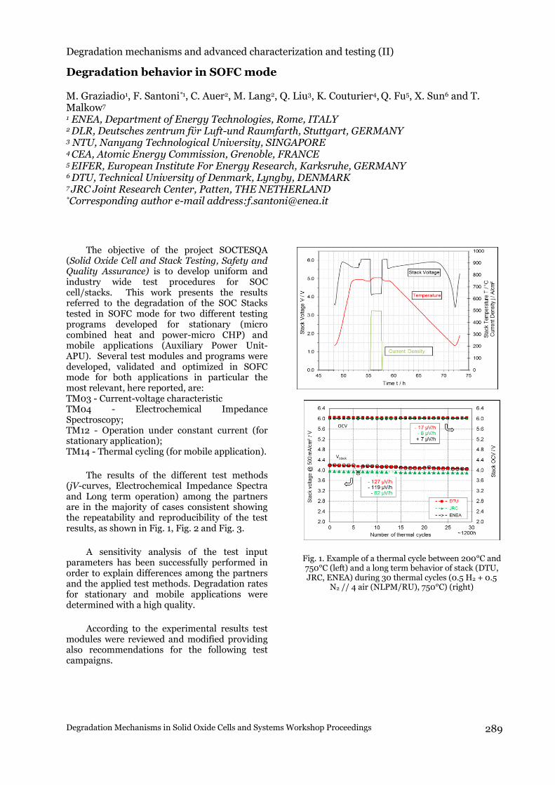
The results of the different test methods (jV-curves, Electrochemical Impedance Spectra and Long term operation) among the partners are in the majority of cases consistent showing the repeatability and reproducibility of the test results, as shown in Fig. 1, Fig. 2 and Fig. 3.
A sensitivity analysis of the test input parameters has been successfully performed in order to explain differences among the partners and the applied test methods. Degradation rates for stationary and mobile applications were determined with a high quality.
According to the experimental results test modules were reviewed and modified providing also recommendations for the following test campaigns.
Fig. 1. Example of a thermal cycle between 200°C and 750°C (left) and a long term behavior of stack (DTU, JRC, ENEA) during 30 thermal cycles (0.5 H2 + 0.5
N2 // 4 air (NLPM/RU), 750°C) (right)
Chapter or Section
February 17, 2017 ~ Barcelona, Spain 290
Fig. 2. jV curves of stack (DTU) during 30 thermal cycles (750°C, 0.5 H2 + N2 // 4 air (NLPM/RU)) (left) and EIS spectra of RU 3 during 30 thermal cycles at
750°C, DC current of 12 mA/cm2 and 0.5 H2 + 0.5 N2 // 4 air (NLPM/RU) (right)
A sensitivity analysis of the test input parameters has been successfully performed in order to explain differences among the partners and the applied test methods. Degradation rates for stationary and mobile applications were determined with a high quality.
According to the experimental results test modules were reviewed and modified providing also recommendations for the following test campaigns.
Fig. 3. Long term behavior of stacks (DLR,DTU) at
750°C, constant current of 300 mA(cm2 and 0.5 H2 + 0.5 N2 // 4 air (NLPM/RU) (left) and jV curves (DLR) at different operation times at 750°C and 0.5 H2 + 0.5
N2 // 4 air (NLPM/RU) (right)
Acknowledgment The funding of this project within the
European Union’s Seventh Framework Program (FP7/2007-2013) for Fuel Cells and Hydrogen Joint Undertaking (FCH-JU) under the grant agreement number 621245 is gratefully acknowledged.
WORKSHOP PROCEEDINGS
DEGRADATION MECHANISMS IN SOLID OXIDE CELLS AND SYSTEMS
FEBRUARY 17, 2017BARCELONA, SPAIN
Degradation behavior in SOFC modeM. Graziadio, F. Santoni, C. Auer, M. Lang, Q. Liu, K. Couturier, Q. Fu, X. Sun and T. Malkow er, Q. Fu, X. Sun and T. Malkow
Solid Oxide Cell and Stack Testing, Safety and Quality Assurance (SOCTESQA)
Degradation of SOC stacks tested
in SOFC mode operation
M. Graziadio1 , F. Santoni 1, C. Auer2, M. Lang2, Q. Liu3, K. Couturier4, Q. Fu5, X. Sun6, T. Malkow7