334
Dell EMC DD and PowerProtect Hardware Version 7.x Features and Specifications Rev 03 February 2020

Dell EMC DD and PowerProtect HardwareVersion 7.x
Features and SpecificationsRev 03
February 2020

Copyright © 2019-2020 Dell Inc. or its subsidiaries. All rights reserved.
Dell believes the information in this publication is accurate as of its publication date. The information is subject to change without notice.
THE INFORMATION IN THIS PUBLICATION IS PROVIDED “AS-IS.” DELL MAKES NO REPRESENTATIONS OR WARRANTIES OF ANY KIND
WITH RESPECT TO THE INFORMATION IN THIS PUBLICATION, AND SPECIFICALLY DISCLAIMS IMPLIED WARRANTIES OF
MERCHANTABILITY OR FITNESS FOR A PARTICULAR PURPOSE. USE, COPYING, AND DISTRIBUTION OF ANY DELL SOFTWARE DESCRIBED
IN THIS PUBLICATION REQUIRES AN APPLICABLE SOFTWARE LICENSE.
Dell Technologies, Dell, EMC, Dell EMC and other trademarks are trademarks of Dell Inc. or its subsidiaries. Other trademarks may be the property
of their respective owners. Published in the USA.
Dell EMCHopkinton, Massachusetts 01748-91031-508-435-1000 In North America 1-866-464-7381www.DellEMC.com
2 Dell EMC DD and PowerProtect Hardware Features and Specifications

9
13
DD3300 19DD3300 system features.................................................................................. 20DD3300 system specifications...........................................................................21DD3300 storage capacity..................................................................................22Front panel........................................................................................................23
Left control panel.................................................................................23Right control panel...............................................................................25Front disks........................................................................................... 27Service tag...........................................................................................27Rear panel............................................................................................28
Rear panel.........................................................................................................33Product serial number tag (PSNT).......................................................35Rear SSD............................................................................................. 35NIC indicators...................................................................................... 36Power supply indicators....................................................................... 36
DD4200 39DD4200 system features.................................................................................. 40DD4200 system specifications...........................................................................41DD4200 storage capacity..................................................................................42Front Panel....................................................................................................... 43
Power supply units...............................................................................43AC power extender module.................................................................. 43Cooling Fans........................................................................................ 44Solid-state drives................................................................................. 44Front LED Indicators............................................................................ 44
Back Panel........................................................................................................ 47I/O module LEDs.................................................................................. 47Management module and interfaces.....................................................47
I/O modules and slot assignments.................................................................... 49Slot addition rules................................................................................ 49
Internal system components..............................................................................51DIMM modules..................................................................................... 51
DD4200 and ES30 shelf guidelines.................................................................... 51Types of cabinets and power connections........................................... 52Cabling shelves.................................................................................... 62ES30 and DD4200 cabling....................................................................63
DD4200 and DS60 shelf guidelines................................................................... 68Single phase power connections for 40U-P (current racks).................693-phase power connections for 40U-P (current racks)........................ 71DS60 and DD4200 cabling................................................................... 76
DD4500 79
Figures
Tables
Chapter 1
Chapter 2
Chapter 3
CONTENTS
Dell EMC DD and PowerProtect Hardware Features and Specifications 3

DD4500 system features.................................................................................. 80DD4500 system specifications.......................................................................... 81DD4500 storage capacity................................................................................. 82Front Panel....................................................................................................... 83
Power supply units...............................................................................83AC power extender module.................................................................. 83Cooling Fans........................................................................................ 84Solid-state drives................................................................................. 84Front LED Indicators............................................................................ 84
Back Panel........................................................................................................ 87I/O module LEDs..................................................................................87Management module and interfaces.....................................................87
I/O modules and slot assignments.................................................................... 89Slot addition rules................................................................................ 89
Internal system components..............................................................................91DIMM modules..................................................................................... 91
DD4500 and ES30 shelf guidelines.................................................................... 91Single phase power connections for 40U-P (current racks).................92Cabling shelves.................................................................................... 94ES30 and DD4500 cabling................................................................... 94
DD4500 and DS60 shelf guidelines..................................................................100Single phase power connections for 40U-P (current racks)................1013-phase power connections for 40U-P (current racks)...................... 103DS60 and DD4500 cabling..................................................................108
DD6300 115DD6300 system features..................................................................................116DD6300 system specifications......................................................................... 117DD6300 storage capacity................................................................................. 117DD6300 front panel..........................................................................................118
Front LED indicators........................................................................... 119Back panel........................................................................................................121
DD6300 rear SSDs.............................................................................. 121Rear LED indicators.............................................................................121
I/O modules.....................................................................................................124I/O module population rules................................................................125
Internal system components............................................................................ 127DIMMs overview................................................................................. 127
DD6300 and ES30 shelf guidelines.................................................................. 128Types of cabinets and power connections.......................................... 128Cabling shelves................................................................................... 129DD6300, DD6800, and DD9300 shelf configurations.......................... 129
DD6300 and DS60 shelf guidelines..................................................................130shelf configurations............................................................................. 131
DD6800 133DD6800 system features................................................................................. 134DD6800 system specifications........................................................................ 135DD6800 storage capacity................................................................................ 135DD6800 front panel......................................................................................... 136
Front LED indicators...........................................................................136Back panel....................................................................................................... 138
Rear LED indicators............................................................................ 138I/O modules..................................................................................................... 141
Chapter 4
Chapter 5
Contents
4 Dell EMC DD and PowerProtect Hardware Features and Specifications

I/O module population rules................................................................ 142Internal system components............................................................................144
DIMMs overview................................................................................. 144DD6800 and ES30 shelf guidelines.................................................................. 145
Types of cabinets and power connections.......................................... 146Cabling shelves................................................................................... 146DD6300, DD6800, and DD9300 shelf configurations.......................... 147
DD6800 and DS60 shelf guidelines.................................................................. 148shelf configurations............................................................................ 149
DD6900 151DD6900 system features.................................................................................152DD6900 system specifications........................................................................ 153DD6900 storage capacity and configurations.................................................. 154DD6900 front panel.........................................................................................155
Front LEDs......................................................................................... 156DD6900 SSD usage and configurations........................................................... 158Rear panel....................................................................................................... 159
Rear LEDs...........................................................................................160PCIe HBAs....................................................................................................... 161
Slot assignment...................................................................................161I/O population rules............................................................................ 162
DD6900 DIMM configurations......................................................................... 163DD6900, DD9400, and DD9900 storage shelves configurations and capacities....163
DD7200 165DD7200 system features................................................................................. 166DD7200 system specifications.........................................................................167DD7200 storage capacity................................................................................ 168Front Panel......................................................................................................169
Power supply units............................................................................. 169AC power extender module.................................................................169Cooling Fans....................................................................................... 170Solid-state drives................................................................................170Front LED Indicators...........................................................................170
Back Panel.......................................................................................................173I/O module LEDs.................................................................................173Management module and interfaces................................................... 173
I/O modules and slot assignments................................................................... 175Slot addition rules............................................................................... 175
Internal system components............................................................................ 177DIMM modules.................................................................................... 177
DD7200 and ES30 shelf guidelines...................................................................177Single phase power connections for 40U-P (current racks)............... 178Cabling shelves...................................................................................180ES30 and DD7200 cabling.................................................................. 180
DD7200 and DS60 shelf guidelines.................................................................. 186Single phase power connections for 40U-P (current racks)............... 1863-phase power connections for 40U-P (current racks)...................... 188DS60 and DD7200 cabling.................................................................. 193
DD9300 199system features.............................................................................................. 200
Chapter 6
Chapter 7
Chapter 8
Contents
Dell EMC DD and PowerProtect Hardware Features and Specifications 5

system specifications...................................................................................... 201DD9300 storage capacity................................................................................ 201DD9300 front panel........................................................................................ 202
Front LED indicators.......................................................................... 203Back panel...................................................................................................... 204
Rear LED indicators........................................................................... 204I/O modules.................................................................................................... 207
I/O module population rules............................................................... 208Internal system components............................................................................210
DIMMs overview.................................................................................210DD9300 and ES30 shelf guidelines...................................................................211
Types of cabinets and power connections.......................................... 212Cabling shelves................................................................................... 212DD6300, DD6800, and DD9300 shelf configurations.......................... 213
DD9300 and DS60 shelf guidelines..................................................................2143-phase power connections for 40U-P (current racks)...................... 215shelf configurations............................................................................ 215
DD9400 217DD9400 system features................................................................................. 218DD9400 system specifications........................................................................ 219DD9400 storage capacity and configurations................................................. 220DD9400 front panel......................................................................................... 221
Front LEDs.........................................................................................222DD9400 SSD usage and configurations...........................................................224Rear panel.......................................................................................................225
Rear LEDs.......................................................................................... 226PCIe HBAs...................................................................................................... 227
Slot assignment..................................................................................227I/O population rules........................................................................... 228
DD9400 DIMM configurations........................................................................ 229DD6900, DD9400, and DD9900 storage shelves configurations and capacities....229
DD9500 231System features..............................................................................................232System specifications..................................................................................... 233DD9500 storage capacity............................................................................... 234Front panel......................................................................................................236
Front LED indicators.......................................................................... 236Solid-state drives............................................................................... 239
Rear panel.......................................................................................................240Power supply units..............................................................................241Management module.......................................................................... 241Rear LED indicators........................................................................... 242Available I/O modules.........................................................................243Ethernet I/O module options..............................................................244Fibre Channel I/O modules.................................................................244SAS I/O modules............................................................................... 245
I/O module slot assignments...........................................................................245Slot addition rules.............................................................................. 246
Internal System Components.......................................................................... 247DIMM modules...................................................................................249Cooling fans....................................................................................... 249
Chapter 9
Chapter 10
Contents
6 Dell EMC DD and PowerProtect Hardware Features and Specifications

DD9500 and ES30 shelf guidelines................................................................. 250Types of cabinets and power connections.......................................... 251Cabling shelves...................................................................................251DD9500 and cabling........................................................................... 251
DD9500 and DS60 shelf guidelines................................................................. 2523-phase power connections for 40U-P (current racks)......................253DD9500 and DD9800 cabling.............................................................253
DD9800 255DD9800 system features................................................................................ 256DD9800 system specifications........................................................................257DD9800 storage capacity............................................................................... 258DD9800 front panel........................................................................................ 260
Front LED indicators.......................................................................... 260Solid-state drives............................................................................... 263
Rear panel.......................................................................................................264Power supply units.............................................................................265Management module..........................................................................265Rear LED indicators........................................................................... 266Available I/O modules.........................................................................267Ethernet I/O module options..............................................................268Fibre Channel I/O modules.................................................................268SAS I/O modules............................................................................... 269
I/O module slot assignments...........................................................................269Slot addition rules.............................................................................. 270
Internal system components............................................................................271DIMM modules................................................................................... 273Cooling fans....................................................................................... 273
DD9800 and ES30 shelf guidelines..................................................................273Types of cabinets and power connections..........................................274Cabling shelves.................................................................................. 275DD9500 and cabling........................................................................... 275
DD9800 and DS60 shelf guidelines................................................................. 2763-phase power connections for 40U-P (current racks)...................... 277DD9500 and DD9800 cabling............................................................. 277
DD9900 279DD9900 system features................................................................................ 280DD9900 system specifications........................................................................ 281DD9900 storage capacity and configurations................................................. 282DD9900 front panel........................................................................................ 283
Front LEDs.........................................................................................284DD9900 SSD usage and configurations.......................................................... 286DD9900 rear panel.......................................................................................... 287
Rear LEDs.......................................................................................... 288PCIe HBAs...................................................................................................... 288
Slot assignment................................................................................. 289I/O population rules........................................................................... 289
DD9900 DIMM configurations........................................................................ 290DD6900, DD9400, and DD9900 storage shelves configurations and capacities....291
DS60 293DS60 overview................................................................................................294
Chapter 11
Chapter 12
Chapter 13
Contents
Dell EMC DD and PowerProtect Hardware Features and Specifications 7

DS60 site requirements.................................................................................. 294DS60 hardware specifications........................................................................ 295DS60 front panel ............................................................................................296Back panel.......................................................................................................297Disk enclosure interior ....................................................................................297Expansion shelf cables.....................................................................................301Ports...............................................................................................................302
ES30 303ES30 overview................................................................................................304Site requirements........................................................................................... 304ES30 hardware specifications.........................................................................305Front panel..................................................................................................... 306Back panel...................................................................................................... 307Ports............................................................................................................... 310
ES40 311ES40 overview.................................................................................................312Dimensions and weights.................................................................................. 312Power requiremements....................................................................................312DAE-to-DAE copper cabling............................................................................ 314Product service tag......................................................................................... 314System operating limits................................................................................... 315
Environmental recovery......................................................................316
FS15 317Overview of FS15 SSD drives.......................................................................... 318Site requirements............................................................................................ 318FS15 hardware specifications.......................................................................... 319FS15 front panel..............................................................................................320Back panel...................................................................................................... 322Status LEDs.................................................................................................... 324
FS25 325Overview of FS25 SSD drives......................................................................... 326Dimensions and weight................................................................................... 326Power requirements........................................................................................326DAE-to-DAE copper cabling............................................................................328Product service tag.........................................................................................328Air quality requirements.................................................................................. 328Shock and Vibration........................................................................................329System operating limits................................................................................... 331
Environmental recovery..................................................................... 332Shipping and storage requirements.................................................................332
333
Chapter 14
Chapter 15
Chapter 16
Chapter 17
Index
Contents
8 Dell EMC DD and PowerProtect Hardware Features and Specifications
Front panel........................................................................................................................23Left control panel..............................................................................................................24Right control panel............................................................................................................26Disk LEDs..........................................................................................................................27Service tag........................................................................................................................28Rear panel.........................................................................................................................282 x 10 GbE module............................................................................................................ 294 x 16 Gbps FC module......................................................................................................30PSNT location...................................................................................................................30Disk LEDs.......................................................................................................................... 31NIC LEDs........................................................................................................................... 31Power supply LED.............................................................................................................32Rear panel.........................................................................................................................332 x 10 GbE module.............................................................................................................344 x 16 Gbps FC module......................................................................................................34PSNT location...................................................................................................................35Disk LEDs..........................................................................................................................35NIC LEDs.......................................................................................................................... 36Power supply LED............................................................................................................. 37Front panel components................................................................................................... 43System LEDs.....................................................................................................................44System LED legend label...................................................................................................45Power supply LEDs........................................................................................................... 45Fan and SSD LEDs............................................................................................................ 46Features on rear of chassis............................................................................................... 47Interfaces on the management module............................................................................. 48Top view of SP module with SP cover removed................................................................ 51Single phase power connections for the 40U-P expansion rack........................................ 53Single phase power connections for the DD4200, DD4500, and DD7200 .........................54Single phase power connections for the Expansion Rack..................................................55Single phase power connections for the DD4200, DD4500, and DD7200......................... 56Single phase power connections for the Expansion Rack.................................................. 57Single phase power connections for the DD4200, DD4500, and DD7200......................... 58Recommended 3-phase delta power connections for the Expansion Rack........................59Recommended 3-phase delta power connections for DD4200, DD4500, and DD7200......60Recommended 3-phase wye power connections for the Expansion Rack.......................... 613-phase wye power connections for DD4200, DD4500, and DD7200............................... 62Recommended DD4200 cabling........................................................................................ 65Recommended cabling for DD4200 integrated with Avamar............................................. 66Recommended cabling for DD4200 system with extended retention software or DD CloudTier................................................................................................................................... 67Recommended cabling for DD4200 with extended retention and integrated with Avamar......................................................................................................................................... 68Single phase power connections for DD4200, DD4500, and DD7200 systems.................. 703-phase delta power connections for DS60 expansion shelves (full-racked).....................723-phase delta power connections for DD4200, DD4500, and DD7200 systems................ 733-phase wye power connections for DS60 expansion shelves (full-racked)...................... 743-phase wye power connections for DD4200, DD4500, and DD7200 systems..................75Recommended cabling for DD4200 (3TB drives).............................................................. 77Recommended cabling for DD4200 (3TB drives) with Extended Retention Software ...... 78Front panel components................................................................................................... 83System LEDs.....................................................................................................................84System LED legend label...................................................................................................85
12345678910111213141516171819202122232425262728293031323334353637383940
41
42434445464748495051
FIGURES
Dell EMC DD and PowerProtect Hardware Features and Specifications 9

Power supply LEDs........................................................................................................... 85Fan and SSD LEDs............................................................................................................ 86Features on rear of chassis............................................................................................... 87Interfaces on the management module............................................................................. 88Top view of SP module with SP cover removed................................................................ 91Single phase power connections for DD4200, DD4500, and DD7200 systems..................93Recommended DD4500 cabling........................................................................................ 97Recommended cabling for DD4500 integrated with Avamar............................................. 98Recommended cabling for DD4500 with extended retention software or DD Cloud Tier.. 99Recommended cabling for DD4500 with extended retention and integrated with Avamar........................................................................................................................................ 100Single phase power connections for DD4200, DD4500, and DD7200 systems................ 1023-phase delta power connections for DS60 expansion shelves (full-racked)................... 1043-phase delta power connections for DD4200, DD4500, and DD7200 systems...............1053-phase wye power connections for DS60 expansion shelves (full-racked).................... 1063-phase wye power connections for DD4200, DD4500, and DD7200 systems................ 107Recommended cabling for DD4500 (3TB drives)............................................................ 109Recommended cabling for DD4500 (3TB drives) with Extended Retention software.......110Recommended cabling for DD4500 with DD Cloud Tier.................................................... 111Recommended cabling for DD4500 (4TB drives)............................................................. 112Recommended cabling for DD4500 (4TB drives) with Extended Retention software.......113Front LED indicators........................................................................................................ 119Rear LED indicators..........................................................................................................121I/O module Power/Service LED location......................................................................... 123Onboard network port LEDs............................................................................................ 124I/O module slot numbering.............................................................................................. 124CPU and memory locations..............................................................................................127Front LED indicators........................................................................................................ 137Rear LED indicators......................................................................................................... 138I/O module Power/Service LED location......................................................................... 140Onboard network port LEDs.............................................................................................141I/O module slot numbering............................................................................................... 141CPU and memory locations..............................................................................................144System dimensions.......................................................................................................... 153DD6900 front panel......................................................................................................... 155Front left control panel status LEDs................................................................................ 156Front right control panel power button LEDs................................................................... 157Drive LEDs.......................................................................................................................158DD6900 SSD slot assignment..........................................................................................158System rear panel............................................................................................................159Onboard ID and iDRAC LEDs........................................................................................... 160Slot numbering................................................................................................................ 162Front panel components.................................................................................................. 169System LEDs................................................................................................................... 170System LED legend label.................................................................................................. 171Power supply LEDs...........................................................................................................171Fan and SSD LEDs........................................................................................................... 172Features on rear of chassis.............................................................................................. 173Interfaces on the management module............................................................................ 174Top view of SP module with SP cover removed............................................................... 177Single phase power connections for DD4200, DD4500, and DD7200 systems.................179Recommended DD7200 cabling....................................................................................... 182Recommended cabling for DD7200 integrated with Avamar............................................ 183Recommended cabling for DD7200 with extended retention software or DD Cloud Tier. 184Recommended cabling for DD7200 with extended retention and integrated with Avamar........................................................................................................................................ 185
52535455565758596061
6263646566676869707172737475767778798081828384858687888990919293949596979899100101102103104105
Figures
10 Dell EMC DD and PowerProtect Hardware Features and Specifications

Single phase power connections for DD4200, DD4500, and DD7200 systems.................1873-phase delta power connections for DS60 expansion shelves (full-racked)................... 1893-phase delta power connections for DD4200, DD4500, and DD7200 systems...............1903-phase wye power connections for DS60 expansion shelves (full-racked)..................... 1913-phase wye power connections for DD4200, DD4500, and DD7200 systems................ 192Recommended cabling for DD7200 (3TB drives)............................................................. 194Recommended cabling for DD7200 (4TB drives).............................................................195Recommended cabling for DD7200 (3TB drives) with Extended Retention software...... 196Recommended cabling for DD7200 with DD Cloud Tier................................................... 197Recommended cabling for DD7200 (4TB drives) with Extended Retention software...... 198Front LED indicators....................................................................................................... 203Rear LED indicators........................................................................................................ 204I/O module Power/Service LED location........................................................................ 206Onboard network port LEDs............................................................................................207I/O module slot numbering..............................................................................................207CPU and memory locations..............................................................................................210System dimensions..........................................................................................................219DD9400 front panel......................................................................................................... 221Front left control panel status LEDs................................................................................222Front right control panel power button LEDs.................................................................. 223Drive LEDs...................................................................................................................... 224DD9400 SSD slot assignment......................................................................................... 224System rear panel........................................................................................................... 225Onboard ID and iDRAC LEDs...........................................................................................226Slot numbering................................................................................................................228Front panel components................................................................................................. 236Service LEDs...................................................................................................................237Power button.................................................................................................................. 238Front LEDs......................................................................................................................238SSD drives...................................................................................................................... 239Features on rear of chassis............................................................................................. 240Serial number tag location.............................................................................................. 240Four power supplies.........................................................................................................241Management module....................................................................................................... 2411000BaseT Ethernet ports.............................................................................................. 242Rear LEDs....................................................................................................................... 242Power supply LEDs......................................................................................................... 243Location of NVRAM and I/O modules............................................................................. 245SP module ......................................................................................................................248Releasing a memory riser ............................................................................................... 248Open fan tray..................................................................................................................249Front panel components................................................................................................. 260Service LEDs................................................................................................................... 261Power button.................................................................................................................. 262Front LEDs......................................................................................................................262SSD drives...................................................................................................................... 263Features on rear of chassis............................................................................................. 264Serial number tag location...............................................................................................264Four power supplies........................................................................................................ 265Management module.......................................................................................................2651000BaseT Ethernet ports.............................................................................................. 266Rear LEDs.......................................................................................................................266Power supply LEDs......................................................................................................... 267Location of NVRAM and I/O modules............................................................................. 269SP module ......................................................................................................................272Releasing a memory riser ............................................................................................... 272
106107108109110111112113114115116117118119120121122123124125126127128129130131132133134135136137138139140141142143144145146147148149150151152153154155156157158159160161
Figures
Dell EMC DD and PowerProtect Hardware Features and Specifications 11

Open fan tray.................................................................................................................. 273System dimensions.......................................................................................................... 281DD9900 front panel........................................................................................................ 283Front left control panel status LEDs................................................................................284Front right control panel power button LEDs.................................................................. 285Drive LEDs...................................................................................................................... 286DD9900 rear panel.......................................................................................................... 287Onboard ID and iDRAC LEDs...........................................................................................288Slot numbering................................................................................................................290DS60 front panel.............................................................................................................296DS60 back panel ............................................................................................................ 297Fans and disk drives inside the disk enclosure.................................................................298Drives as packs............................................................................................................... 300HD-mini-SAS connector.................................................................................................. 301ES30 front panel (bezel removed).................................................................................. 306Front panel LEDs............................................................................................................ 306Back panel: Power modules and controllers.................................................................... 308Power Supply A LEDs..................................................................................................... 309FS15 front panel (bezel removed)...................................................................................320Front panel LEDs............................................................................................................. 321Back panel: Power modules and controllers.................................................................... 322Power Supply A LEDs......................................................................................................323Rear panel overview........................................................................................................324
162163164165166167168169170171172173174175176177178179180181182183184
Figures
12 Dell EMC DD and PowerProtect Hardware Features and Specifications

DD3300 system features.................................................................................................. 20DD3300 system specifications...........................................................................................21System operating environment..........................................................................................21DD3300 storage capacity..................................................................................................22Front disk slot numbers.....................................................................................................23Rear disk slot numbers......................................................................................................29Network daughter card port identifiers.............................................................................29Optional 10 GbE module port identifiers............................................................................29Optional 16 Gbps FC module port identifiers..................................................................... 30NIC LED states.................................................................................................................. 31Rear disk slot numbers......................................................................................................34Network daughter card port identifiers............................................................................. 34Optional 10 GbE module port identifiers............................................................................ 34Optional 16 Gbps FC module port identifiers..................................................................... 34NIC LED states................................................................................................................. 36DD4200 system features.................................................................................................. 40DD4200 system specifications...........................................................................................41System operating environment..........................................................................................41DD4200 storage capacity..................................................................................................42LED status indicators........................................................................................................ 46DD4200 slot assignments..................................................................................................49DD4200 and ES30 shelf configuration.............................................................................. 52Minimum and maximum configurations............................................................................. 64DD4200 cabling information..............................................................................................64DD4200 and DS60 shelf configuration.............................................................................. 69Minimum and maximum configurations............................................................................. 76DD4500 system features.................................................................................................. 80DD4500 system specifications.......................................................................................... 81System operating environment..........................................................................................81DD4500 storage capacity..................................................................................................82LED status indicators........................................................................................................ 86DD4500 slot assignments................................................................................................. 89DD4500 and ES30 shelf configuration.............................................................................. 92Minimum and maximum configurations............................................................................. 95DD4500 cabling information............................................................................................. 95DD4200 and DS60 shelf configuration............................................................................. 101Minimum and maximum configurations............................................................................108DD6300 system features..................................................................................................116DD6300 system specifications......................................................................................... 117System operating environment.........................................................................................117DD6300 storage capacity................................................................................................. 117DD6300 AIO capacity....................................................................................................... 118DD6300 AIO configuration............................................................................................... 119DD6300 AIO expanded configuration............................................................................... 119Front LEDs....................................................................................................................... 119DD6300 rear SSDs........................................................................................................... 121I/O LEDs..........................................................................................................................123Onboard network port LEDs............................................................................................ 124DD6300 I/O slot module mapping....................................................................................125I/O module slot population rules...................................................................................... 125DD6300 memory DIMM configuration............................................................................. 127Memory locations - CPU 0...............................................................................................127Memory locations - CPU 1............................................................................................... 127
1234567891011121314151617181920212223242526272829303132333435363738394041424344454647484950515253
TABLES
Dell EMC DD and PowerProtect Hardware Features and Specifications 13

DD6300 and ES30 shelf configuration............................................................................. 128Minimum and maximum configurations............................................................................ 129DD6300 and DS60 shelf configuration............................................................................. 131Minimum configurations................................................................................................... 131DD6800 system features................................................................................................. 134DD6800 system specifications........................................................................................ 135System operating environment........................................................................................135DD6800 storage capacity................................................................................................ 135DD6800 DLH SSD requirements...................................................................................... 136DD6800 DLH configuration drive layout.......................................................................... 136DD6800 DLH expanded configuration drive layout.......................................................... 136Front LEDs.......................................................................................................................137I/O LEDs..........................................................................................................................140Onboard network port LEDs.............................................................................................141I/O module slot mapping..................................................................................................142I/O module slot population rules...................................................................................... 142memory DIMM configuration........................................................................................... 144Memory locations - CPU 0...............................................................................................144Memory locations - CPU 1............................................................................................... 145DD6800 and ES30 shelf configuration.............................................................................145Minimum and maximum configurations............................................................................ 147DD6800 and DS60 shelf configuration.............................................................................148Minimum configurations.................................................................................................. 149DD6900 system features................................................................................................. 152DD6900 system specifications........................................................................................ 153System operating environment........................................................................................153DD6900 storage capacity and configurations.................................................................. 154HA configuration requirements........................................................................................ 154Front panel features........................................................................................................ 155Front LEDs...................................................................................................................... 155System health and system ID indicator codes..................................................................156Right control panel features ........................................................................................... 157iDRAC Direct LED indicator codes .................................................................................. 157DD6900 SSD configurations............................................................................................158SSD boot drives...............................................................................................................159PSU FRU LEDs................................................................................................................ 160DD6900 slot assignments.................................................................................................161Memory configurations....................................................................................................163DD6900 DIMM configuration CPU 1................................................................................ 163DD6900 DIMM configuration CPU 2................................................................................163Shelves shipped from factory, in rack..............................................................................164Shelves shipped from factory, boxed...............................................................................164Additional shelves supported........................................................................................... 164Shelf usable capacities.................................................................................................... 164Supported shelf count per chain......................................................................................164DD7200 system features................................................................................................. 166DD7200 system specifications......................................................................................... 167System operating environment........................................................................................ 167DD7200 storage capacity................................................................................................ 168LED status indicators....................................................................................................... 172DD7200 slot assignments................................................................................................ 175DD7200 and ES30 shelf configuration............................................................................. 178Minimum and maximum configurations.............................................................................181DD7200 cabling information............................................................................................. 181DD7200 and DS60 shelf configuration.............................................................................186Minimum and maximum configurations............................................................................ 193
54555657585960616263646566676869707172737475767778798081828384858687888990919293949596979899100101102103104105106107108109
Tables
14 Dell EMC DD and PowerProtect Hardware Features and Specifications

system features.............................................................................................................. 200system specifications...................................................................................................... 201System operating environment........................................................................................201DD9300 storage capacity................................................................................................ 201DD9300 DLH SSD requirements..................................................................................... 202DD9300 DLH configuration drive layout..........................................................................202DD9300 DLH expanded configuration drive layout..........................................................202Front LEDs......................................................................................................................203I/O LEDs.........................................................................................................................206Onboard network port LEDs............................................................................................207I/O module slot mapping.................................................................................................208I/O module slot population rules..................................................................................... 208memory DIMM configuration........................................................................................... 210Memory locations - CPU 0.............................................................................................. 210Memory locations - CPU 1................................................................................................211DD9300 and ES30 shelf configuration..............................................................................211Minimum and maximum configurations............................................................................ 213DD9300 and DS60 shelf configuration.............................................................................214Minimum configurations.................................................................................................. 216DD9400 system features................................................................................................. 218DD9400 system specifications.........................................................................................219System operating environment........................................................................................219DD9400 storage capacity and configurations..................................................................220HA configuration requirements....................................................................................... 220Front panel features........................................................................................................ 221Front LEDs...................................................................................................................... 221System health and system ID indicator codes................................................................. 222Right control panel features ...........................................................................................223iDRAC Direct LED indicator codes ..................................................................................223DD9400 SSD configurations........................................................................................... 224SSD boot drives.............................................................................................................. 225PSU FRU LEDs............................................................................................................... 226DD9400 slot assignments................................................................................................227Memory configurations................................................................................................... 229DD9400 base DIMM configuration CPU 1....................................................................... 229DD9400 base DIMM configuration CPU 2.......................................................................229Shelves shipped from factory, in rack............................................................................. 230Shelves shipped from factory, boxed.............................................................................. 230Additional shelves supported...........................................................................................230Shelf usable capacities....................................................................................................230Supported shelf count per chain..................................................................................... 230DD9500 system features................................................................................................ 232DD9500/DD9800 system specifications......................................................................... 233DD9500 storage capacity................................................................................................234DD9500 with ES30 SAS shelves..................................................................................... 234DD9500 with DS60 shelves............................................................................................ 235Front panel LED status indicators................................................................................... 239Rear LED status indicators..............................................................................................243Physical to logical port mapping example........................................................................ 244DD9500 I/O module slot assignments.............................................................................245I/O module slot population rules......................................................................................247DD9500 memory configurations..................................................................................... 249DD9500 and ES30 shelf configuration............................................................................ 250Minimum and maximum configurations........................................................................... 252DD9500 and DS60 shelf configuration............................................................................253Minimum and maximum configurations........................................................................... 254
110111112113114115116117118119120121122123124125126127128129130131132133134135136137138139140141142143144145146147148149150151152153154155156157158159160161162163164165
Tables
Dell EMC DD and PowerProtect Hardware Features and Specifications 15

DD9800 system features................................................................................................ 256DD9800 system specifications........................................................................................ 257DD9800 storage capacity............................................................................................... 258DD9800 with ES30 SAS shelves..................................................................................... 258DD9800 with DS60 shelves............................................................................................ 259Front panel LED status indicators................................................................................... 263Rear LED status indicators..............................................................................................267Physical to logical port mapping example........................................................................268DD9800 I/O module slot assignments.............................................................................269I/O module slot population rules...................................................................................... 271DD9800 memory configurations......................................................................................273DD9800 and ES30 shelf configuration............................................................................ 274Minimum and maximum configurations........................................................................... 275DD9800 and DS60 shelf configuration............................................................................ 277Minimum and maximum configurations........................................................................... 278DD9900 system features................................................................................................ 280DD9900 system specifications........................................................................................ 281System operating environment....................................................................................... 282DD9900 storage capacity and configurations..................................................................282HA configuration requirements....................................................................................... 282Front panel features........................................................................................................283Front LEDs......................................................................................................................283System health and system ID indicator codes................................................................. 284Right control panel features ...........................................................................................285iDRAC Direct LED indicator codes ................................................................................. 285DD9900 SSD configurations........................................................................................... 286SSD boot drives.............................................................................................................. 286PSU FRU LEDs............................................................................................................... 288DD9900 slot assignments............................................................................................... 289Memory configurations....................................................................................................291DD9900 base DIMM configuration CPU 1........................................................................ 291DD9900 base DIMM configuration CPU 2....................................................................... 291Shelves shipped from factory, in rack..............................................................................291Shelves shipped from factory, boxed.............................................................................. 292Additional shelves supported...........................................................................................292Shelf usable capacities....................................................................................................292Supported shelf count per chain..................................................................................... 292DS60 shelf set support................................................................................................... 294Site requirements............................................................................................................294Hardware specifications..................................................................................................295LED status lights.............................................................................................................296Status lights visible from rear of disk enclosure ............................................................. 297LED status lights.............................................................................................................298Physical drives................................................................................................................ 300HD-mini-SAS to mini-SAS cable part numbers................................................................ 301HD-mini-SAS to ES30 host and ES30 expansion port cable part numbers...................... 302ES30 shelves in a set...................................................................................................... 304site requirements............................................................................................................ 304ES30 hardware specifications.........................................................................................305System operating environment....................................................................................... 305Status lights visible from front of disk enclosure.............................................................307Status lights visible from rear of disk enclosure ............................................................. 309ES40 shelves in a set....................................................................................................... 312Dimensions and weight.................................................................................................... 312AC power specifications.................................................................................................. 313DC power specifications.................................................................................................. 313
166167168169170171172173174175176177178179180181182183184185186187188189190191192193194195196197198199200201202203204205206207208209210211212213214215216217218219220221
Tables
16 Dell EMC DD and PowerProtect Hardware Features and Specifications
System operating limits................................................................................................... 315System operating limits (meets ASHRAE equipment class A3) .......................................315Number of SSD drives and model compatibilty................................................................ 318FS15 site requirements.................................................................................................... 318FS15 hardware specifications.......................................................................................... 319Status lights visible from front of disk enclosure............................................................. 321Status lights visible from rear of disk enclosure ............................................................. 323Status LEDs.................................................................................................................... 324Number of SSD drives and model compatibilty............................................................... 326Dimensions and weight ...................................................................................................326AC power specifications..................................................................................................327DC power specifications..................................................................................................327System operating limits................................................................................................... 331System operating limits (meets ASHRAE equipment class A3) .......................................331Shipping and storage requirements.................................................................................332
222223224225226227228229230231232233234235236
Tables
Dell EMC DD and PowerProtect Hardware Features and Specifications 17

Tables
18 Dell EMC DD and PowerProtect Hardware Features and Specifications
CHAPTER 1
DD3300
This chapter contains the following topics:
l DD3300 system features.......................................................................................................20l DD3300 system specifications............................................................................................... 21l DD3300 storage capacity...................................................................................................... 22l Front panel............................................................................................................................ 23l Rear panel............................................................................................................................. 33
Dell EMC DD and PowerProtect Hardware Features and Specifications 19

DD3300 system features
Table 1 DD3300 system features
Feature 4 TB configuration 8 TB configuration 16 TB configuration 32 TB configuration
RackHeight
2U, supported in four-post racks only
Power 1 or 2 hot-swappable power units
Fans 6 hot swappable fans, installed in two fan assemblies (3 fans per fan assembly)
Rackmounting
Rack mount kit included with each system. Adjustable between 24 - 36 in. (60.9–76.2 cm).
Processor 1 x 8-core Intel 4110 series, hyperthreaded
Voltage 100–240 V~. Frequency: 50 Hz to 60 Hz.
Internal3.5"drives(front)
4 x 4 TB HDD 10 x 4 TB HDD 10 x 4 TB HDD 12 x 4 TB HDD
Internal3.5"drives(middle)
N/A N/A N/A 4 x 4 TB HDD
Internal3.5"drives(rear)
N/A 1 x 480 GB SSD for NVRAMa
NIC 4 x 1 GbE or 4 x 10 GbE (always present)b + 2 x 10 GbE (optional)
FC (DDVTL only)
4 x 16 Gbps (optional)
Memory 16 GB or 24 GBc 48 GB 48 GB or 56 GBd 64 GB
a. The SSD is for use as an NVRAM device, and for SSD Cache Tier storage only. The maximum supported SSD CacheTier capacity is one percent of the Active Tier capacity. Other SSD-based functions such as Random I/O handlingare not supported for use with the SSD.
b. Starting with DD OS 6.2, DD3300 systems ship with a 4 x 10 GbE RJ-45 network daughter card.c. 24 GB of memory is required to use the FC module for DD VTL.d. A 16 TB system will have 56 GB of memory if it was a 4 TB system equipped with the FC module, and was later
upgraded to 16 TB.
Note: DD OS may report less storage and memory than indicated in this table. The unreportedresources are used for internal system processes.
DD3300
20 Dell EMC DD and PowerProtect Hardware Features and Specifications

DD3300 system specifications
Table 2 DD3300 system specifications
Watts BTU/hr Weight Width Depth Height
750 2891 72.91 lb/33.1 kg 17.09 in/43.4 cm 28.17 inches/71.55cm
3.42 in/8.68 cm
Table 3 System operating environment
Operating Temperature 50° to 95° F (10° to 35° C), derate 1.1° Cper 1000 feet, above 7500 feet up to 10,000feet
Operating Humidity 20% to 80%, non-condensing
Non-operating Temperature -40° to +149° F (-40° to +65° C)
Operating Acoustic Noise Sound power, LWAd: 7.52 bels. Soundpressure, LpAm: 56.4 dB. (Declared noiseemission per ISO 9296.)
DD3300
Dell EMC DD and PowerProtect Hardware Features and Specifications 21

DD3300 storage capacityThe table lists the capacities of the systems. The system internal indexes and other productcomponents use variable amounts of storage, depending on the type of data and the sizes of files.If you send different datasets to otherwise identical systems, one system may, over time, haveroom for more or less actual backup data than another.
Table 4 DD3300 storage capacity
Configuration
Internaldisks -physicalab
Internal disks -virtual
Raw storage Usablestorage(local)c
Cloud storage SSD metadatacache storage
4 TBcapacity /16GB memory
4 x 4 TB7200 RPMNLSAS
l 1 x 4 TB forActive Tier
l 1 x 1 TB forDD Cloud Tiermetadata
16 TB 4 TB 8 TB N/A
8 TBcapacity/48GB memory
10 x 4 TB7200 RPMNLSAS
l 4 x 4 TB forActive Tier
l 2 x 1 TB forDD Cloud Tiermetadata
40 TB 8 TB 16 TB 160 GB
16 TBcapacity/48GB memory
10 x 4 TB7200 RPMNLSAS
l 4 x 4 TB forActive Tier
l 2 x 1 TB forDD Cloud Tiermetadata
40 TB 16 TB 32 TB 160 GB
32 TBcapacity/64GB memory
l 12 x 4 TB7200RPMNLSAS(front)
l 4 x 4 TB7200RPMNLSAS(middle)
l 8 x 4 TB forActive Tier
l 4 x 1 TB forDD Cloud Tiermetadata
64 TB 32 TB 64 TB 320 GB
a. The internal hard drives are configured in a RAID6 configuration. RAID6 provides the system with the ability towithstand the simultaneous failure of two hard drives, or the failure of one hard drive while another hard drive is stillrebuilding after a drive replacement operation.
b. After replacing a disk, it takes approximately 18 hours to complete the rebuild operation on the new disk, but maytake longer depending on the amount of activity on the system.
c. The system compensates for the required file system overhead, so the reported usable capacity matches thespecified usable capacity.
DD3300
22 Dell EMC DD and PowerProtect Hardware Features and Specifications

Front panelThe DD3300 front panel consists of two control panels, which contain system LEDs and ports,twelve 3.5" disk drive bays, and the service tag. Figure 1 on page 23 shows the locations of thefront panel components.
Figure 1 Front panel
1. Left control panel2. 3.5" disk drive3. Right control panel4. Service tag.
Disk layout
The following table shows the physical location of each disk slot.
Note: Although the physical slots are numbered starting from 0, the software identifies theslots starting at 1.
Table 5 Front disk slot numbers
Slot 0 (SW slot 1) Slot 3 (SW slot 4) Slot 6 (SW slot 7) Slot 9 (SW slot 10)
Slot 1 (SW slot 2) Slot 4 (SW slot 5) Slot 7 (SW slot 8) Slot 10 (SW slot 11)
Slot 2 (SW slot 3) Slot 5 (SW slot 6) Slot 8 (SW slot 9) Slot 11 (SW slot 12)
Left control panelThe left control panel contains system status LEDs. Figure 2 on page 24 shows the panel.
DD3300
Dell EMC DD and PowerProtect Hardware Features and Specifications 23

Figure 2 Left control panel
1. System status LEDs2. System health and system ID indicator3. iDRAC Quick Sync 2 wireless indicator (Not supported)
The system status LEDs turn solid amber if the system experiences an error in any of the followingcategories. Under normal operating conditions, the system status LEDs remain off. From top tobottom, the five system status LEDs are:
l Drive indicator
l Temperature indicator
DD3300
24 Dell EMC DD and PowerProtect Hardware Features and Specifications

l Electrical indicator
l Memory indicator
l PCIe indicator
The system health and system ID indicator has the following states:
l Solid blue: Indicator is in system health mode. System is on and healthy.
l Blinking blue: Indicator is in system ID mode.Note: Press the System Health and System ID button to switch the indicator betweensystem health and system ID modes.
l Solid amber: System is in fail-safe mode.
l Blinking amber: System is experiencing a fault.
Right control panelThe right control panel contains the system power button, and system maintenance ports. Figure 3on page 26 shows the panel.
DD3300
Dell EMC DD and PowerProtect Hardware Features and Specifications 25

Figure 3 Right control panel
1. Power button2. Not Supported -- 2 x USB 2.0 ports (Not supported)3. Not Supported -- iDRAC Direct port (micro USB 2.0)4. iDRAC Direct LED5. Not Used -- VGA port
DD3300 supports the use of the iDRAC Direct port for console access. The iDRAC Direct LEDlights up when the iDRAC Direct port is connected. The LED has the following the states:
l Solid green for two seconds: Service laptop is connected.
l Flashing green: Connected laptop is recognized.
l Off: Nothing is connected to the iDRAC Direct port.
DD3300
26 Dell EMC DD and PowerProtect Hardware Features and Specifications

Front disksThe DD3300 system contains 4, 10, or 12 front-mounted 3.5" HDDs, depending on the capacityconfiguration. Each HDD has an activity indicator, and a status indicator. Figure 4 on page 27shows the HDD indicators.
Figure 4 Disk LEDs
1. HDD activity indicator2. HDD status indicator
The HDD activity indicator blinks during drive activity.
The HDD status indicator has the following states:
l Flashes green twice per second: Identifying drive or preparing for removal.
l Off: Drive is ready for removal.
l Flashes green, then amber, then turns off: Predicted drive failure.
l Flashes amber four times per second: Drive failed.
l Solid green: Drive online.
l Flashes green slowly: Drive rebuilding.
l Flashes green for three seconds, then amber for three seconds, then turns off: Rebuildstopped.
Service tagThe DD3300 system service tag is located at the front of the system, in the lower right-handcorner of the chassis. This tag is on all DD3300 systems, and includes the product serial number.
DD3300
Dell EMC DD and PowerProtect Hardware Features and Specifications 27

Figure 5 Service tag
1. Information tag (top view)2. Information tag (back view)3. OpenManage Mobile (OMM) label4. iDRAC MAC address and secure password label5. Service tag
Rear panelThe DD3300 rear panel contains the system serial port, NIC cards, power supplies, and 3.5" drivebays. shows the rear of the system.
Figure 6 Rear panel
1. Full height PCIe expansion card slots
l The top slot is for the optional 2 x 10 GbE NIC
l The middle slot is for the optional 4 x 16 Gbps FC module
l The bottom slot is not supported
2. Not Supported -- Half height PCIe expansion card slot
DD3300
28 Dell EMC DD and PowerProtect Hardware Features and Specifications
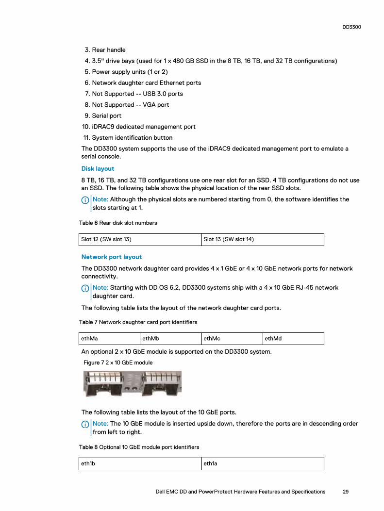
3. Rear handle
4. 3.5" drive bays (used for 1 x 480 GB SSD in the 8 TB, 16 TB, and 32 TB configurations)
5. Power supply units (1 or 2)
6. Network daughter card Ethernet ports
7. Not Supported -- USB 3.0 ports
8. Not Supported -- VGA port
9. Serial port
10. iDRAC9 dedicated management port
11. System identification button
The DD3300 system supports the use of the iDRAC9 dedicated management port to emulate aserial console.
Disk layout
8 TB, 16 TB, and 32 TB configurations use one rear slot for an SSD. 4 TB configurations do not usean SSD. The following table shows the physical location of the rear SSD slots.
Note: Although the physical slots are numbered starting from 0, the software identifies theslots starting at 1.
Table 6 Rear disk slot numbers
Slot 12 (SW slot 13) Slot 13 (SW slot 14)
Network port layout
The DD3300 network daughter card provides 4 x 1 GbE or 4 x 10 GbE network ports for networkconnectivity.
Note: Starting with DD OS 6.2, DD3300 systems ship with a 4 x 10 GbE RJ-45 networkdaughter card.
The following table lists the layout of the network daughter card ports.
Table 7 Network daughter card port identifiers
ethMa ethMb ethMc ethMd
An optional 2 x 10 GbE module is supported on the DD3300 system.
Figure 7 2 x 10 GbE module
The following table lists the layout of the 10 GbE ports.
Note: The 10 GbE module is inserted upside down, therefore the ports are in descending orderfrom left to right.
Table 8 Optional 10 GbE module port identifiers
eth1b eth1a
DD3300
Dell EMC DD and PowerProtect Hardware Features and Specifications 29

FC port layout
An optional 4 x 16 Gbps FC module is supported on the DD3300 system.
Figure 8 4 x 16 Gbps FC module
The following table lists the layout of the FC ports.
Table 9 Optional 16 Gbps FC module port identifiers
22a 22b 22c 22d
Product serial number tag (PSNT)
Some DD3300 systems have a PSNT tag located on the rear of the system, attached to the arm inthe center of the chassis. If this tag is not present, the product serial number is available from theservice tag located on the front of the system.
Note: Service tag on page 27 describes the front-mounted service tag.
Figure 9 PSNT location
If present, the PSNT is identified by the part number (PN) 900-555-024. The 14 digitalphanumeric string starting with "APM000" that accompanies the part number is the systemserial number. This serial number is the default system password for serial console and systemmanager access.
Rear SSDThe DD3300 8 TB, 16 TB, and 32 TB configurations use one rear-mounted 480 GB 2.5" SSD. TheSSD has an activity indicator, and a status indicator.
DD3300
30 Dell EMC DD and PowerProtect Hardware Features and Specifications

Figure 10 Disk LEDs
1. HDD activity indicator2. HDD status indicator
The HDD activity indicator blinks during drive activity.
The HDD status indicator has the following states:
l Flashes green twice per second: Identifying drive or preparing for removal.
l Off: Drive is ready for removal.
l Flashes green, then amber, then turns off: Predicted drive failure.
l Flashes amber four times per second: Drive failed.
l Solid green: Drive online.
NIC indicatorsAll network ports on the DD3300 system have link and activity LED indicators.
Figure 11 NIC LEDs
1. Link LED indicator2. Activity LED indicator
The NIC LEDs have the following states:
Table 10 NIC LED states
Link indicator state Activity indicator state Meaning
Green Blinking green The NIC is connected to avalid network at its maximum
DD3300
Dell EMC DD and PowerProtect Hardware Features and Specifications 31

Table 10 NIC LED states (continued)
Link indicator state Activity indicator state Meaning
port speed and data is beingsent or received.
Amber Blinking green The NIC is connected to avalid network at less than itsmaximum port speed and datais being sent or received.
Green Off The NIC is connected to avalid network at its maximumport speed and data is notbeing sent or received.
Amber Off The NIC is connected to avalid network at less than itsmaximum port speed and datais not being sent or received.
Blinking green Off NIC identify is enabledthrough the NIC configurationutility.
Power supply indicatorsThe power supply unit has an illuminated, translucent handle that functions as a status LED.
Figure 12 Power supply LED
The indicator has the following states:
l Green: Valid power source is connected, and the PSU is operational.
l Blinking amber: Indicates a problem with the PSU.
l Off: Power is not connected.
l Blinking green: Firmware update is in progress.CAUTION Do not disconnect the power cord or unplug the PSU when updating firmware. Iffirmware update is interrupted, the PSUs do not function.
DD3300
32 Dell EMC DD and PowerProtect Hardware Features and Specifications

l Blinking green, then off: When hot-plugging a PSU, the PSU handle blinks green five times at arate of 4 Hz and turns off. This indicates a PSU mismatch with respect to efficiency, featureset, health status, or supported voltage.
Rear panelThe DD3300 rear panel contains the system serial port, NIC cards, power supplies, and 3.5" drivebays. shows the rear of the system.
Figure 13 Rear panel
1. Full height PCIe expansion card slots
l The top slot is for the optional 2 x 10 GbE NIC
l The middle slot is for the optional 4 x 16 Gbps FC module
l The bottom slot is not supported
2. Not Supported -- Half height PCIe expansion card slot
3. Rear handle
4. 3.5" drive bays (used for 1 x 480 GB SSD in the 8 TB, 16 TB, and 32 TB configurations)
5. Power supply units (1 or 2)
6. Network daughter card Ethernet ports
7. Not Supported -- USB 3.0 ports
8. Not Supported -- VGA port
9. Serial port
10. iDRAC9 dedicated management port
11. System identification button
The DD3300 system supports the use of the iDRAC9 dedicated management port to emulate aserial console.
Disk layout
8 TB, 16 TB, and 32 TB configurations use one rear slot for an SSD. 4 TB configurations do not usean SSD. The following table shows the physical location of the rear SSD slots.
DD3300
Dell EMC DD and PowerProtect Hardware Features and Specifications 33
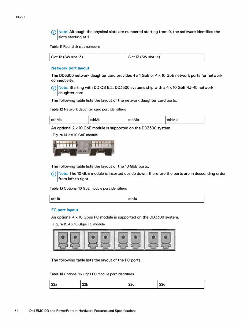
Note: Although the physical slots are numbered starting from 0, the software identifies theslots starting at 1.
Table 11 Rear disk slot numbers
Slot 12 (SW slot 13) Slot 13 (SW slot 14)
Network port layout
The DD3300 network daughter card provides 4 x 1 GbE or 4 x 10 GbE network ports for networkconnectivity.
Note: Starting with DD OS 6.2, DD3300 systems ship with a 4 x 10 GbE RJ-45 networkdaughter card.
The following table lists the layout of the network daughter card ports.
Table 12 Network daughter card port identifiers
ethMa ethMb ethMc ethMd
An optional 2 x 10 GbE module is supported on the DD3300 system.
Figure 14 2 x 10 GbE module
The following table lists the layout of the 10 GbE ports.
Note: The 10 GbE module is inserted upside down, therefore the ports are in descending orderfrom left to right.
Table 13 Optional 10 GbE module port identifiers
eth1b eth1a
FC port layout
An optional 4 x 16 Gbps FC module is supported on the DD3300 system.
Figure 15 4 x 16 Gbps FC module
The following table lists the layout of the FC ports.
Table 14 Optional 16 Gbps FC module port identifiers
22a 22b 22c 22d
DD3300
34 Dell EMC DD and PowerProtect Hardware Features and Specifications
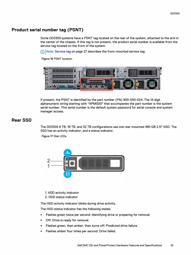
Product serial number tag (PSNT)
Some DD3300 systems have a PSNT tag located on the rear of the system, attached to the arm inthe center of the chassis. If this tag is not present, the product serial number is available from theservice tag located on the front of the system.
Note: Service tag on page 27 describes the front-mounted service tag.
Figure 16 PSNT location
If present, the PSNT is identified by the part number (PN) 900-555-024. The 14 digitalphanumeric string starting with "APM000" that accompanies the part number is the systemserial number. This serial number is the default system password for serial console and systemmanager access.
Rear SSDThe DD3300 8 TB, 16 TB, and 32 TB configurations use one rear-mounted 480 GB 2.5" SSD. TheSSD has an activity indicator, and a status indicator.
Figure 17 Disk LEDs
1. HDD activity indicator2. HDD status indicator
The HDD activity indicator blinks during drive activity.
The HDD status indicator has the following states:
l Flashes green twice per second: Identifying drive or preparing for removal.
l Off: Drive is ready for removal.
l Flashes green, then amber, then turns off: Predicted drive failure.
l Flashes amber four times per second: Drive failed.
DD3300
Dell EMC DD and PowerProtect Hardware Features and Specifications 35
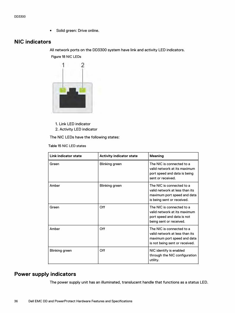
l Solid green: Drive online.
NIC indicatorsAll network ports on the DD3300 system have link and activity LED indicators.
Figure 18 NIC LEDs
1. Link LED indicator2. Activity LED indicator
The NIC LEDs have the following states:
Table 15 NIC LED states
Link indicator state Activity indicator state Meaning
Green Blinking green The NIC is connected to avalid network at its maximumport speed and data is beingsent or received.
Amber Blinking green The NIC is connected to avalid network at less than itsmaximum port speed and datais being sent or received.
Green Off The NIC is connected to avalid network at its maximumport speed and data is notbeing sent or received.
Amber Off The NIC is connected to avalid network at less than itsmaximum port speed and datais not being sent or received.
Blinking green Off NIC identify is enabledthrough the NIC configurationutility.
Power supply indicatorsThe power supply unit has an illuminated, translucent handle that functions as a status LED.
DD3300
36 Dell EMC DD and PowerProtect Hardware Features and Specifications
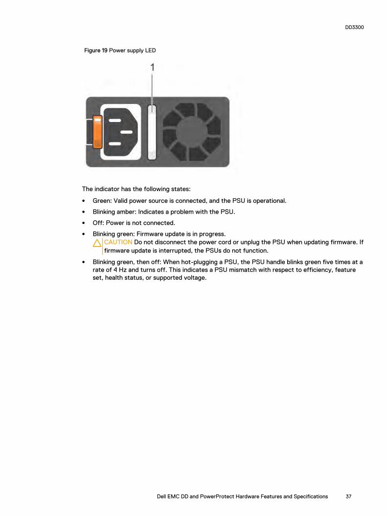
Figure 19 Power supply LED
The indicator has the following states:
l Green: Valid power source is connected, and the PSU is operational.
l Blinking amber: Indicates a problem with the PSU.
l Off: Power is not connected.
l Blinking green: Firmware update is in progress.CAUTION Do not disconnect the power cord or unplug the PSU when updating firmware. Iffirmware update is interrupted, the PSUs do not function.
l Blinking green, then off: When hot-plugging a PSU, the PSU handle blinks green five times at arate of 4 Hz and turns off. This indicates a PSU mismatch with respect to efficiency, featureset, health status, or supported voltage.
DD3300
Dell EMC DD and PowerProtect Hardware Features and Specifications 37
DD3300
38 Dell EMC DD and PowerProtect Hardware Features and Specifications

CHAPTER 2
DD4200
This chapter contains the following topics:
l DD4200 system features.......................................................................................................40l DD4200 system specifications............................................................................................... 41l DD4200 storage capacity...................................................................................................... 42l Front Panel............................................................................................................................43l Back Panel.............................................................................................................................47l I/O modules and slot assignments.........................................................................................49l Internal system components.................................................................................................. 51l DD4200 and ES30 shelf guidelines.........................................................................................51l DD4200 and DS60 shelf guidelines........................................................................................68
Dell EMC DD and PowerProtect Hardware Features and Specifications 39

DD4200 system featuresThe table summarizes the DD4200 system features.
Table 16 DD4200 system features
Feature DD4200 (Base configuration)
Rack height 4U, supported in four-postracks only
Rack mounting Rack mount kit included witheach system. Adjustablebetween 24 - 36 in. (60.9 - 76.2cm).
Power 1 +1 redundant, hot-swappablepower units
Processor Two 8-core processors
NVRAM One 4-GB NVRAM module (andcompanion BBU) for dataintegrity during a power outage
Fans Hot-swappable, redundant, 5
Memory 16 x 8 GB DIMM (128 GB)
Internal drives SSD drives, 3 x 200 GB (base10)
I/O module slots Nine replaceable I/O module(Fibre Channel, Ethernet, andSAS) slots, one BBU, oneNVRAM, and one Managementmodule slot. See Managementmodule and interfaces on page47 and I/O modules and slotassignments on page 49.
Supported capacity Non-extended retention 8 x 2-TB or 5 x 3-TB shelvesadding up to 189 TB of usableexternal capacity.
DD Cloud Tier 189 TB of Active Tier capacity,and 378 TB of Cloud Tiercapacity. 2x3 TB shelves arerequired to store DD Cloud Tiermetadata.
DD Extended Retention 24 x 2-TB or 16 x 3-TB shelvesadding up to 378 TB of usableexternal capacity. If lower-capacity 1 TB-drive-basedshelves are used, the maximumconfiguration will also be limited
DD4200
40 Dell EMC DD and PowerProtect Hardware Features and Specifications

Table 16 DD4200 system features (continued)
Feature DD4200 (Base configuration)
by a maximum shelf count of32.
DD4200 system specifications
Table 17 DD4200 system specifications
Model Watts BTU/hr Power Weight Width Depth Height
DD4200 800 2730 800 80 lb / 36.3kg
17.5 in (44.5cm)
33 in (84cm)
7 in (17.8cm)
Table 18 System operating environment
Operating Temperature 50° to 95° F (10° to 35° C), derate 1.1° Cper 1000 feet, above 7500 feet up to 10,000feet
Operating Humidity 20% to 80%, non-condensing
Non-operating Temperature -40° to +149° F (-40° to +65° C)
Operating Acoustic Noise Sound power, LWAd: 7.52 bels. Soundpressure, LpAm: 56.4 dB. (Declared noiseemission per ISO 9296.)
DD4200
Dell EMC DD and PowerProtect Hardware Features and Specifications 41

DD4200 storage capacityData Domain system internal indexes and other product components use variable amounts ofstorage, depending on the type of data and the sizes of files. If you send different data sets tootherwise identical systems, one system may, over time, have room for more or less actual backupdata than another.
Table 19 DD4200 storage capacity
System/ InstalledMemory
Internal Disks(SATA SSDs)
Data StorageSpace
External Storage3
DD4200(2 SAS I/Omodules)
128 GB
2.5 in. 3 @ 200 GBNo User Data
189 TB Up to a maximum of 8 x 2-TBor 5 x 3-TB shelves.
DD4200 with DDCloud Tier1
(3 SAS I/Omodules)
128 GB
2.5 in. 3 @ 200 GBNo User Data
l 189 TB (ActiveTier)
l 72 TB (DDCloud Tiermetadata)
l 378 TB (DDCloud Tier)
Up to a maximum of 8 x 2-TBor 5 x 3-TB shelves.2x3-TB shelves for DD CloudTier metadata.
DD4200 withExtendedRetentionsoftware1 (4 SASI/O modules)128 GB
2.5 in. 3 @ 200 GBNo User Data
378 TB Up to a maximum of 16 x 2-TBand 10 x 3-TB shelves.
1. Data Domain DD4200 controller with DD Extended Retention software.
2. Data Domain DD4200 controller with DD Cloud Tier.
3. The capacity will differ depending on the size of the external storage shelves used. This data based on ES30 shelves.
DD4200
42 Dell EMC DD and PowerProtect Hardware Features and Specifications

Front PanelThe photo shows the hardware features and interfaces on the front of the system.
Figure 20 Front panel components
(1) Filler panel
(2) The red box indicates the system processor (SP) module
(3) SSD drive #1
(4) Fan #0
(5) Power supply #B
(6) AC power disconnect plug
(7) AC power extender module
Power supply unitsA system has two power supply units, numbered A and B from the bottom up. Each power supplyhas its own integral cooling fan. Each power unit has three LEDs (see Figure 22 on page 45) thatindicates the following states:
l AC LED: Glows green when AC input is good
l DC LED: Glows green when DC output is good
l Symbol “!”: Glows solid or blinking amber for fault or attention
The AC power plugs are located to the right of each power supply. These plugs are pulled todisconnect AC power to each power supply.
AC power extender moduleAC power entry is connected at the rear of the system. The AC power extender module providespower to the two power supplies on the front of the system. AC Power plugs are located in thefront. The module is adjacent to the SP module and can be removed and replaced.
DD4200
Dell EMC DD and PowerProtect Hardware Features and Specifications 43

Cooling FansA system contains five hot-swappable cooling fans in a 4+1 redundant configuration. The fansprovide cooling for the processors, DIMMs, IO modules, and the management module. Each fanhas a fault LED which causes the fan housing to glow amber. A system can run with one fanfaulted or removed.
Solid-state drivesA system contains three hot-swappable 2.5" solid-state drive (SSD) bays that are located in thefront and on top of the fan modules. There are four drive bays, with the left-most bay containing ablank. The next drive to the right of the blank is SSD #1, the next is #2, and the right-most baycontains SSD #3. No user backup data is kept on the SSDs.
Each drive has a blue colored power LED and an amber fault LED.
Front LED IndicatorsThe photo below indicates the location of the four system LEDs.
Figure 21 System LEDs
The next photo shows the location of the system LED legend label. Figure 23 on page 45 showsthe power supply LEDs. Other front LEDs are shown in Figure 24 on page 46. LED states aredescribed in Table 20 on page 46.
DD4200
44 Dell EMC DD and PowerProtect Hardware Features and Specifications
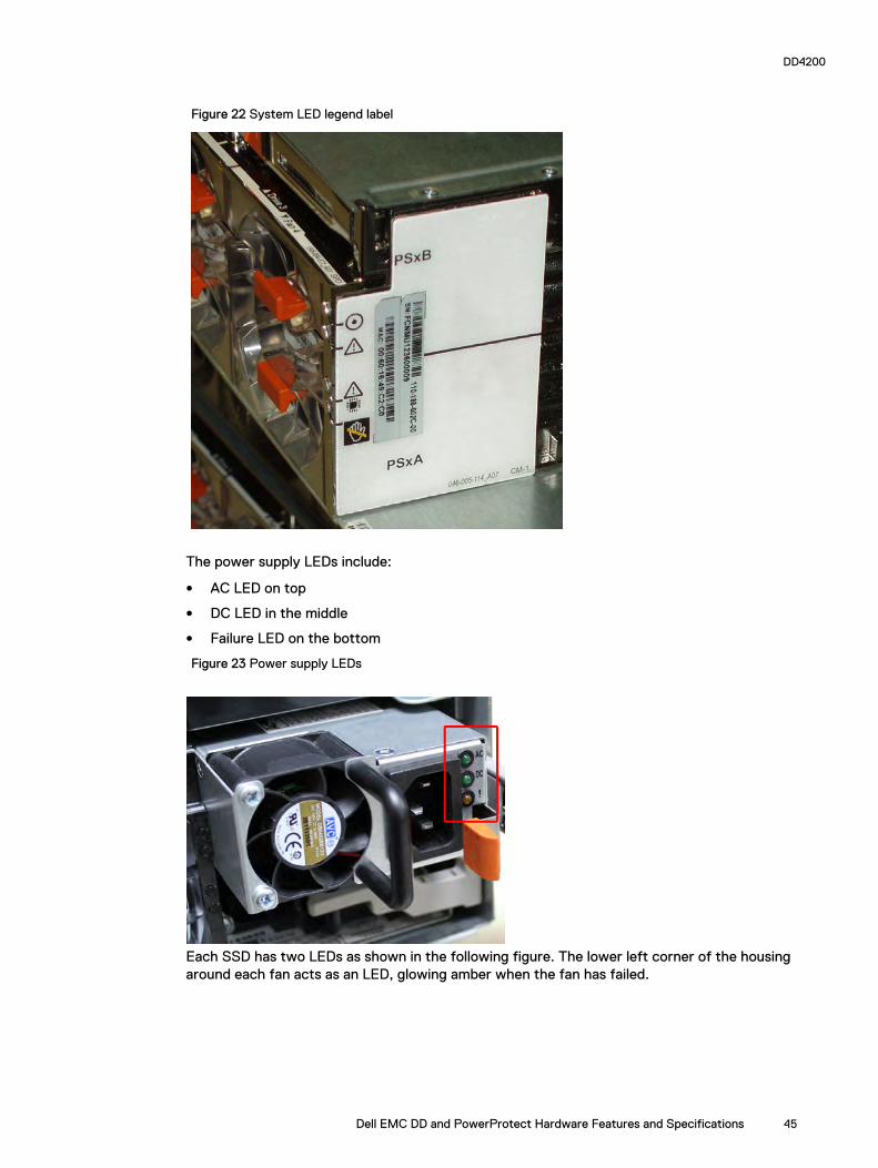
Figure 22 System LED legend label
The power supply LEDs include:
l AC LED on top
l DC LED in the middle
l Failure LED on the bottom
Figure 23 Power supply LEDs
Each SSD has two LEDs as shown in the following figure. The lower left corner of the housingaround each fan acts as an LED, glowing amber when the fan has failed.
DD4200
Dell EMC DD and PowerProtect Hardware Features and Specifications 45

Figure 24 Fan and SSD LEDs
Table 20 LED status indicators
Part Description or Location State
System Dot within a circle (top LED) Blue indicates power on andnormal operation.
System, SP fault Exclamation point within atriangle
Dark indicates normaloperation. Amber indicatesfailure.
System, chassis fault Exclamation point within atriangle with a light below
Dark indicates normaloperation. Yellow indicates afault condition.
System Marked out hand within ablack square (bottom LED)
White warms not to removethe unit.
Power supply AC LED Steady green indicates normalAC power.
Power supply DC LED Steady green indicates normalDC power.
Power supply Failure LED Solid amber indicates a failedpower supply.
SSD Top LED Solid blue, disk ready, blinkswhile busy.
SSD Bottom LED Dark indicates healthy. Solidamber indicates disk fail.
Fan Fan housing The fan housing glows anamber color during fan failure.
DD4200
46 Dell EMC DD and PowerProtect Hardware Features and Specifications

Back PanelThe photo shows the hardware features and interfaces on the back of the system.
Figure 25 Features on rear of chassis
1. Upper level contains all blanks2. AC power extender module3. Management module (slot Mgmt A)4. Red box indicating I/O modules (slots 0-8)5. Battery backup (BBU in slot 9)6. NVRAM module (slot 10)7. Cage covering the BBU and NVRAM combination module8. I/O LED at the end of each I/O module handle9. Location of serial number label/tag
Note: For modules containing multiple ports, the bottom port is numbered as zero (0) withnumbers increasing going upward.
I/O module LEDsEach I/O module ejector handle contains a bi-colored LED. Green indicates normal function, whilean amber color indicates a fault condition.
Management module and interfacesThe management module is on the left-most side when facing the back of the system, in slotMgmt A. The process to remove and add a management module is the same as the I/O modules,however, the management module can only be accommodated in Mgmt A slot.
The management module contains one external LAN connection for management access to the SPmodule. One micro DB-9 connector is included to provide the console. A USB port is provided foruse during service of the system to allow booting from a USB flash device.
DD4200
Dell EMC DD and PowerProtect Hardware Features and Specifications 47

Figure 26 Interfaces on the management module
l 1 - Ethernet port
l 2 - USB port
l 3 - Micro serial port
DD4200
48 Dell EMC DD and PowerProtect Hardware Features and Specifications
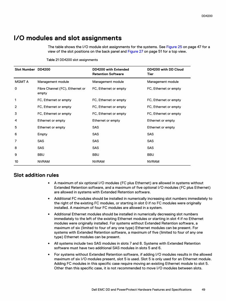
I/O modules and slot assignmentsThe table shows the I/O module slot assignments for the systems. See Figure 25 on page 47 for aview of the slot positions on the back panel and Figure 27 on page 51 for a top view.
Table 21 DD4200 slot assignments
Slot Number DD4200 DD4200 with ExtendedRetention Software
DD4200 with DD CloudTier
MGMT A Management module Management module Management module
0 Fibre Channel (FC), Ethernet orempty
FC, Ethernet or empty FC, Ethernet or empty
1 FC, Ethernet or empty FC, Ethernet or empty FC, Ethernet or empty
2 FC, Ethernet or empty FC, Ethernet or empty FC, Ethernet or empty
3 FC, Ethernet or empty FC, Ethernet or empty FC, Ethernet or empty
4 Ethernet or empty Ethernet or empty Ethernet or empty
5 Ethernet or empty SAS Ethernet or empty
6 Empty SAS SAS
7 SAS SAS SAS
8 SAS SAS SAS
9 BBU BBU BBU
10 NVRAM NVRAM NVRAM
Slot addition rulesl A maximum of six optional I/O modules (FC plus Ethernet) are allowed in systems without
Extended Retention software, and a maximum of five optional I/O modules (FC plus Ethernet)are allowed in systems with Extended Retention software.
l Additional FC modules should be installed in numerically increasing slot numbers immediately tothe right of the existing FC modules, or starting in slot 0 if no FC modules were originallyinstalled. A maximum of four FC modules are allowed in a system.
l Additional Ethernet modules should be installed in numerically decreasing slot numbersimmediately to the left of the existing Ethernet modules or starting in slot 4 if no Ethernetmodules were originally installed. For systems without Extended Retention software, amaximum of six (limited to four of any one type) Ethernet modules can be present. Forsystems with Extended Retention software, a maximum of five (limited to four of any onetype) Ethernet modules can be present.
l All systems include two SAS modules in slots 7 and 8. Systems with Extended Retentionsoftware must have two additional SAS modules in slots 5 and 6.
l For systems without Extended Retention software, if adding I/O modules results in the allowedmaximum of six I/O modules present, slot 5 is used. Slot 5 is only used for an Ethernet module.Adding FC modules in this specific case require moving an existing Ethernet module to slot 5.Other than this specific case, it is not recommended to move I/O modules between slots.
DD4200
Dell EMC DD and PowerProtect Hardware Features and Specifications 49

l Adding Extended Retention software to a system includes adding two SAS modules in slots 5and 6. If the system originally had the maximum of 6 optional I/O modules, the I/O module inslot 5 must be permanently removed from the system.
Fibre Channel (FC) I/O Module OptionAn FC I/O module is a dual-port Fibre Channel module. The optional virtual tape library (VTL)feature requires at least one FC I/O module. Boost over Fiber Channel is optional and the total FCHBAs cannot exceed more than allowable Fibre Channel cards per controller.
Ethernet I/O Module OptionsThe available Ethernet I/O modules are:
l Dual Port 10GBase-SR Optical with LC connectors
l Dual Port 10GBase-CX1 Direct Attach Copper with SPF+ module
l Quad Port 1000Base-T Copper with RJ-45 connectors
l Quad port 2 port 1000Base-T Copper (RJ45) /2 port 1000Base-SR Optical
DD4200
50 Dell EMC DD and PowerProtect Hardware Features and Specifications

Internal system componentsThe photo shows the system with the system processor (SP) module that is removed from thechassis and the SP cover removed.
Figure 27 Top view of SP module with SP cover removed
l 1 - Front of system
l 2 - Four groups of 4 DIMM cards
DIMM modulesDD4200 systems contain 16 x 8 GB of memory DIMM.
DD4200 and ES30 shelf guidelines
The Data Domain system rediscovers newly configured shelves after it restarts. You can power offthe system and recable shelves to any other position in a set, or to another set. To take advantageof this flexibility, you need to follow these rules before making any cabling changes:
l Do not exceed the maximum shelf configuration values for your Data Domain system as listedin the following table below.
l Use the Installation and Setup Guide for your Data Domain system to minimize the chance of acabling mistake.
l A Data Domain system cannot exceed its maximum raw external shelf capacity, regardless ofadded shelf capacity.
l ES30 SATA shelves must be on their own chain.
DD4200
Dell EMC DD and PowerProtect Hardware Features and Specifications 51
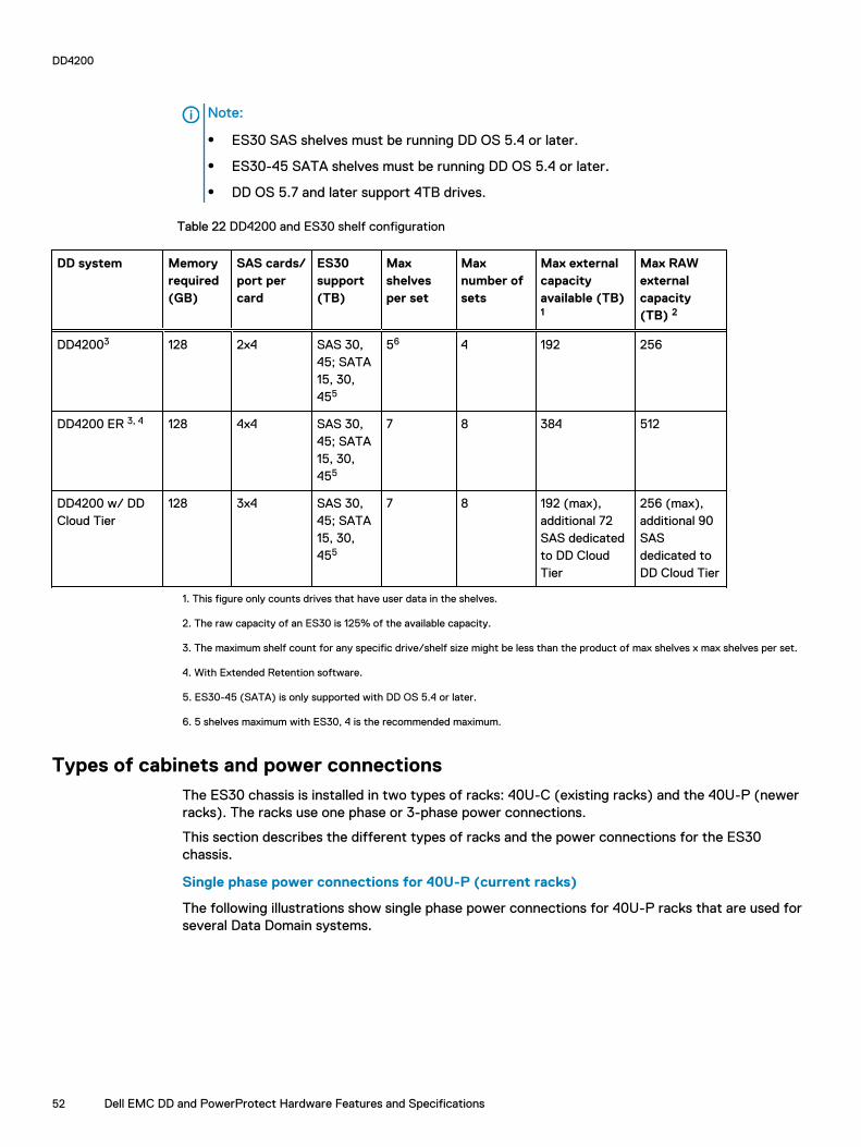
Note:
l ES30 SAS shelves must be running DD OS 5.4 or later.
l ES30-45 SATA shelves must be running DD OS 5.4 or later.
l DD OS 5.7 and later support 4TB drives.
Table 22 DD4200 and ES30 shelf configuration
DD system Memoryrequired(GB)
SAS cards/port percard
ES30support(TB)
Maxshelvesper set
Maxnumber ofsets
Max externalcapacityavailable (TB)1
Max RAWexternalcapacity(TB) 2
DD42003 128 2x4 SAS 30,45; SATA15, 30,455
56 4 192 256
DD4200 ER 3, 4 128 4x4 SAS 30,45; SATA15, 30,455
7 8 384 512
DD4200 w/ DDCloud Tier
128 3x4 SAS 30,45; SATA15, 30,455
7 8 192 (max),additional 72SAS dedicatedto DD CloudTier
256 (max),additional 90SASdedicated toDD Cloud Tier
1. This figure only counts drives that have user data in the shelves.
2. The raw capacity of an ES30 is 125% of the available capacity.
3. The maximum shelf count for any specific drive/shelf size might be less than the product of max shelves x max shelves per set.
4. With Extended Retention software.
5. ES30-45 (SATA) is only supported with DD OS 5.4 or later.
6. 5 shelves maximum with ES30, 4 is the recommended maximum.
Types of cabinets and power connectionsThe ES30 chassis is installed in two types of racks: 40U-C (existing racks) and the 40U-P (newerracks). The racks use one phase or 3-phase power connections.
This section describes the different types of racks and the power connections for the ES30chassis.
Single phase power connections for 40U-P (current racks)
The following illustrations show single phase power connections for 40U-P racks that are used forseveral Data Domain systems.
DD4200
52 Dell EMC DD and PowerProtect Hardware Features and Specifications

Figure 28 Single phase power connections for the 40U-P expansion rack
DD4200
Dell EMC DD and PowerProtect Hardware Features and Specifications 53

Figure 29 Single phase power connections for the DD4200, DD4500, and DD7200
Single phase power connections for 40U-C (older racks)
The following illustrations show single phase power connections for 40U-C racks that are used forseveral Data Domain systems.
DD4200
54 Dell EMC DD and PowerProtect Hardware Features and Specifications

Figure 30 Single phase power connections for the Expansion Rack
DD4200
Dell EMC DD and PowerProtect Hardware Features and Specifications 55

Figure 31 Single phase power connections for the DD4200, DD4500, and DD7200
3-Phase power connections for 40U-C (older racks)
The following illustrations show single phase power connections for 40U-C racks that are used forseveral Data Domain systems.
DD4200
56 Dell EMC DD and PowerProtect Hardware Features and Specifications

Figure 32 Single phase power connections for the Expansion Rack
DD4200
Dell EMC DD and PowerProtect Hardware Features and Specifications 57

Figure 33 Single phase power connections for the DD4200, DD4500, and DD7200
3-Phase power connections for 40U-P (current racks)
Some environments use 3-phase power for 40U-P racks that are used for several Data Domainsystems. In those situations, it is desirable to balance the current draw across all three phases. Therecommended 3-phase power cabling attempts to do that, but an optimal configuration dependson the specific installation. The following illustrations show recommended 3-phase powerconnections for several Data Domain systems.
Note: The next few diagrams show recommended 3-phase delta power connections.
DD4200
58 Dell EMC DD and PowerProtect Hardware Features and Specifications
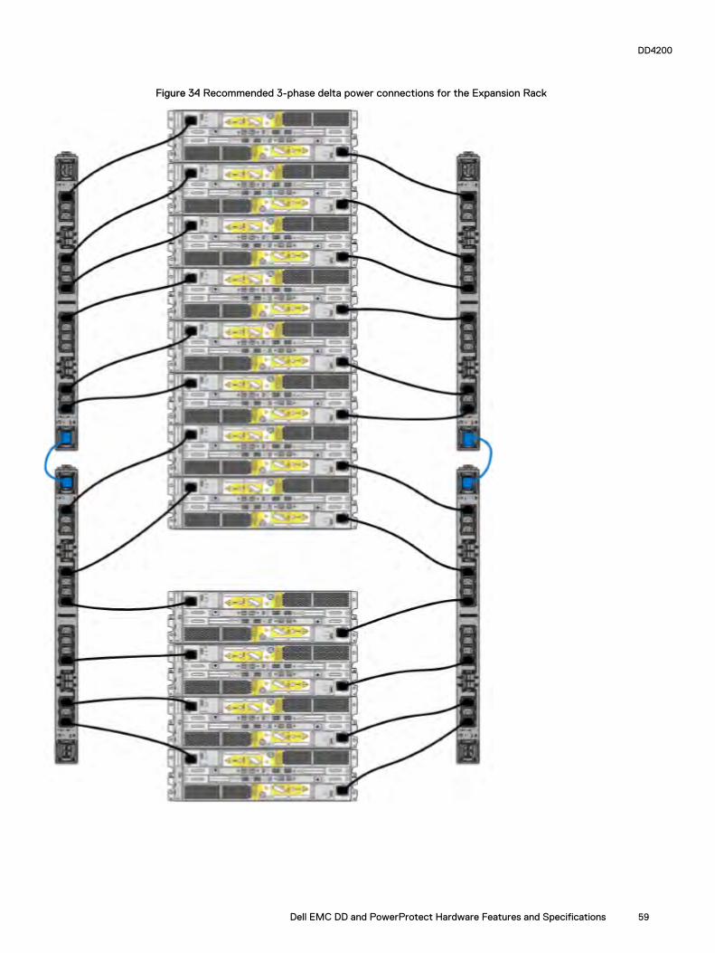
Figure 34 Recommended 3-phase delta power connections for the Expansion Rack
DD4200
Dell EMC DD and PowerProtect Hardware Features and Specifications 59

Figure 35 Recommended 3-phase delta power connections for DD4200, DD4500, and DD7200
Note: The next few diagrams show recommended 3-phase wye power connections.
DD4200
60 Dell EMC DD and PowerProtect Hardware Features and Specifications

Figure 36 Recommended 3-phase wye power connections for the Expansion Rack
DD4200
Dell EMC DD and PowerProtect Hardware Features and Specifications 61
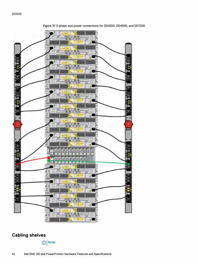
Figure 37 3-phase wye power connections for DD4200, DD4500, and DD7200
Cabling shelves
Note:
DD4200
62 Dell EMC DD and PowerProtect Hardware Features and Specifications

l Before cabling the shelves, physically install all shelves in the racks. Refer to the rail kitinstallation instructions included with the ES30 shelf for rack mounting.
l The documentation refers to two SAS HBAs. If only one HBA is allowed in a system, thenuse another port as defined later for that specific system.
l On an HA system, add cables from the second node to open ports at the end of the sets.The ports on the second node must connect to the same sets as the corresponding portson the first node.
Ports on the system’s SAS HBA cards connect directly to a shelf controller’s host port. Forredundancy, you need to create dual paths by using a port on one SAS HBA card to connect to oneshelf controller in each shelf set, and a port on another SAS HBA card to connect to another shelfcontroller in the same shelf set. With dual paths, if one SAS HBA card fails, the shelf is stilloperational. However, in the unlikely event any single shelf becomes completely disconnected frompower or SAS cables and becomes disconnected from a previously operational shelf, the filesystem goes down and the shelf is not operational. This is considered a double failure.
There are two kinds of configurations: one shelf in a set or multiple shelves in a set.
ES30 and DD4200 cablingThere are a few rules that must be followed when adding a mixture of ES20, ES30 SATA, andES30 SAS shelves to your system. If a system does not follow ALL of these rules it is not alegitimate configuration.
Prerequisites:
l Follow the minimum and maximum shelf capacity configuration provided in the table.
l You cannot have ES20 and ES30 shelves in the same set.
l You cannot have ES30 SATA and ES30 SAS shelves in the same set.
l You cannot exceed the maximum amount of raw capacity displayed in the product's cablingtable.
l The maximum number of shelves displayed in the product's cabling table cannot be exceeded.
l You cannot have more than four ES20s in a single set (maximum preference is three).
l You cannot have more than five ES30s in a single set (maximum preference is four).
l You can have a maximum of seven ES30s for systems with Extended Retention software.
l There are no specific placement or cabling requirements for the metadata shelves for DD CloudTier configurations. These shelves can be installed and cabled the same way as standard ES30shelves.
Note: An ES20 requires more power than an ES30. Ensure that your rack is configured tohandle the power needs.
The tables below show how to configure a mixed system. To use the tables, go to the appropriatesystem. Then find the number of ES20s that are to be configured in the first column. The nextcolumn defines the number of ES20 sets. If there are multiple rows with the same number ofES20s then pick the row with the appropriate number of ES20 SATA shelves. The next column inthat row defines the number of sets of ES30 SATA shelves. Finally, there may be entries for thenumber of desired ES30 SAS shelves and the number of sets to be used.
If the combinations of shelves exceed the supported usable storage, there may not be an entry.The entries are based on the smallest usable storage per shelf type (12TB for ES20, 12 TB forES30 SATA, and 24TB for ES30 SAS). Always check that the sum of the usable storage of all ofthe shelves does not exceed the supported usable storage of the configuration.
DD4200
Dell EMC DD and PowerProtect Hardware Features and Specifications 63

Table 23 Minimum and maximum configurations
System Minimumappliance shelfcount
Maximum applianceshelf count
DD Cloud Tiersystems in TB
Extended Retentionsystems (ER) in TB
Max shelvesfor ER
4200(192)
1 16 l 189
l 90 formetadata
l DD OS 5.4 and earlier:576
l DD OS 5.5 and later:385
32
Systems without Extended Retention or DD Cloud Tier all support four chains. The following tablesshow combinations of ES20 and ES30 shelves. For combinations of any two types of shelves,these tables can be used as a guide.
Table 24 DD4200 cabling information
DD4200
ES20 ES20 chains ES30 SATA ES30 SATAchains
ES30 SAS ES30 SASchains
13-16 4 0 0 0 0
9-12 3 1-5 1 0 0
9-12 3 0 0 1-3 1
5-8 2 6-10 2 0 0
5-8 2 1-5 1 1-5 1
5-8 2 0 0 5 2
5-8 2 0 0 1-4 1
1-4 1 8-12 3 0 0
1-4 1 6-10 2 1-5 1
1-4 1 1-5 1 1-4 1
1-4 1 1-5 1 5-7 2
1-4 1 0 0 1-4 1
1-4 1 0 0 5-7 2
0 0 13-16 4 0 0
0 0 9-12 3 1-3 1
0 0 5-8 2 1-4 1
0 0 5-8 2 5 2
0 0 1-4 1 1-4 1
0 0 1-4 1 5-7 2
0 0 0 0 1-4 1
0 0 0 0 5-8 2
DD4200
64 Dell EMC DD and PowerProtect Hardware Features and Specifications
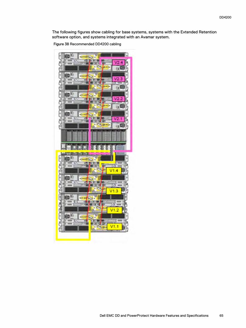
The following figures show cabling for base systems, systems with the Extended Retentionsoftware option, and systems integrated with an Avamar system.
Figure 38 Recommended DD4200 cabling
DD4200
Dell EMC DD and PowerProtect Hardware Features and Specifications 65

Figure 39 Recommended cabling for DD4200 integrated with Avamar
DD4200
66 Dell EMC DD and PowerProtect Hardware Features and Specifications
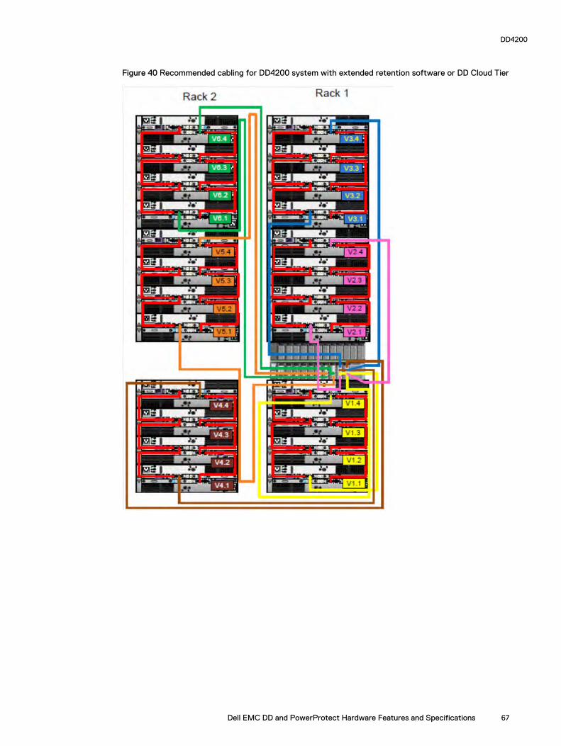
Figure 40 Recommended cabling for DD4200 system with extended retention software or DD Cloud Tier
DD4200
Dell EMC DD and PowerProtect Hardware Features and Specifications 67

Figure 41 Recommended cabling for DD4200 with extended retention and integrated with Avamar
DD4200 and DS60 shelf guidelines
The Data Domain system rediscovers newly configured shelves after it restarts. You can power offthe system and recable shelves to any other position in a set, or to another set. To take advantageof this flexibility, you need to follow these rules before making any cabling changes:
l Do not exceed the maximum shelf configuration values for your Data Domain system as listedin the following table.
l For redundancy, the two connections from a Data Domain system to a set of shelves must useports on different SAS I/O modules.
DD4200
68 Dell EMC DD and PowerProtect Hardware Features and Specifications

l Use the Installation and Setup Guide for your Data Domain system to minimize the chance of acabling mistake.
l A Data Domain system cannot exceed its maximum raw external shelf capacity, regardless ofadded shelf capacity.
l ES30 SATA shelves must be on their own chain.
l If ES30 SAS shelves are on the same chain as a DS60, the maximum number of shelves on thatchain is 5.
l DD OS 5.7.1 does not support HA with SATA drives.
Table 25 DD4200 and DS60 shelf configuration
DD system Memoryrequired(GB)
SAScards/port percard
DS60 support(TB)
Maxshelvesper set
Maxnumber ofsets
Maxexternalcapacityavailable(TB)1
Max RAWexternalcapacity(TB)
DD4200 128 2x4 SAS 45 1 4 192 240
DD4200 ER 2 128 4x4 SAS 45 2 8 384 480
Note: An entry of 45 corresponds to DS60-3 models and an entry of 60 corresponds toDS60-4 models.
1. This column only counts drives that have user data in the shelves. For example, a DS60 4-240 has 192TB.
2. With Extended Retention software.
Single phase power connections for 40U-P (current racks)The following figures show single phase power connections for several Data Domain systems.
DD4200
Dell EMC DD and PowerProtect Hardware Features and Specifications 69

Figure 42 Single phase power connections for DD4200, DD4500, and DD7200 systems
DD4200
70 Dell EMC DD and PowerProtect Hardware Features and Specifications
3-phase power connections for 40U-P (current racks)Some environments use 3-phase power for 40U-P racks used for several Data Domain systems. Inthose situations it is desirable to balance the current draw across all 3 phases. The recommended3-phase power cabling attempts to do that, but an optimal configuration is dependent on thespecific installation. The following figures show recommended 3-phase power connections forseveral Data Domain systems.
Note: The next few diagrams show recommended 3-phase delta power connections.
DD4200
Dell EMC DD and PowerProtect Hardware Features and Specifications 71

Figure 43 3-phase delta power connections for DS60 expansion shelves (full-racked)
DD4200
72 Dell EMC DD and PowerProtect Hardware Features and Specifications

Figure 44 3-phase delta power connections for DD4200, DD4500, and DD7200 systems
Note: The next few diagrams show recommended 3-phase wye power connections.
DD4200
Dell EMC DD and PowerProtect Hardware Features and Specifications 73

Figure 45 3-phase wye power connections for DS60 expansion shelves (full-racked)
DD4200
74 Dell EMC DD and PowerProtect Hardware Features and Specifications

Figure 46 3-phase wye power connections for DD4200, DD4500, and DD7200 systems
DD4200
Dell EMC DD and PowerProtect Hardware Features and Specifications 75

DS60 and DD4200 cablingThere are a few rules that must be followed when adding a mixture of DS60 and other shelf typesto your system.
CAUTION If a system does not follow all these rules, it is not a legitimate configuration.
Prerequisites:
l You cannot exceed the maximum amount of usable capacity displayed in cabling table for eachsystem.
l You cannot exceed the maximum number of shelves displayed in cabling table for each system.
l You cannot connect more than two DS60 shelves in a single set.
Table 26 Minimum and maximum configurations
System Appliance maximum Minimum appliance shelf count
DD4200 192 TB 1
Mixing DS60, ES30, and ES20 shelves:
The non-Extended Retention versions of these systems all support four chains.
Extra planning and reconfiguration may be required to add DS60 shelves to system with ES20shelves, ES30 SATA shelves, or a combination of shelves.
l The ES20 shelves must be on their own set. Minimize the ES20 set count by combining up tofour ES20s per set.
l ES30 SATA shelves must also be on their own sets. Minimize the ES30 set count by combiningup to five ES30s per set. If required, combine up to seven ES30 SAS shelves per set tominimize the set count.
l A set can contain a maximum of two DS60 shelves and, if required because of otherrestrictions, add ES30 SAS shelves up to a maximum of five shelves in that set.
Note: The configuration rules apply also to Extended Retention systems.
The following figures show cabling for base systems and systems with the Extended Retentionsoftware.
Note: It is recommended that the DS60 shelf with the greater number of drives should alwaysbe placed in the bottom position.
DD4200
76 Dell EMC DD and PowerProtect Hardware Features and Specifications

Figure 47 Recommended cabling for DD4200 (3TB drives)
Note: One DS60 shelf can have 60 drives and the second DS60 shelf can have 15drives.
DD4200
Dell EMC DD and PowerProtect Hardware Features and Specifications 77

Figure 48 Recommended cabling for DD4200 (3TB drives) with Extended Retention Software
Note: With four shelves, two DS60 shelves can have 60 drives each and the otherDS60 shelves can only have 15 drives each. It is also possible to configure two fullDS60 shelves and one DS60 shelf with 30 drives.
DD4200
78 Dell EMC DD and PowerProtect Hardware Features and Specifications
CHAPTER 3
DD4500
This chapter contains the following topics:
l DD4500 system features.......................................................................................................80l DD4500 system specifications...............................................................................................81l DD4500 storage capacity......................................................................................................82l Front Panel............................................................................................................................83l Back Panel.............................................................................................................................87l I/O modules and slot assignments.........................................................................................89l Internal system components.................................................................................................. 91l DD4500 and ES30 shelf guidelines.........................................................................................91l DD4500 and DS60 shelf guidelines...................................................................................... 100
Dell EMC DD and PowerProtect Hardware Features and Specifications 79

DD4500 system featuresThe table summarizes the DD4500 system features.
Table 27 DD4500 system features
Feature DD4500
Rack height 4U, supported in four-postracks only
Rack mounting Rack mount kit included witheach system. Adjustablebetween 24 - 36 in. (60.9 - 76.2cm).
Power 1 +1 redundant, hot-swappablepower units
Processor Two 8-core processors
NVRAM One 4-GB NVRAM module (andcompanion BBU) for dataintegrity during a power outage
Fans Hot-swappable, redundant, 5
Memory 8 x 8 GB DIMM + 8 x 16 GBDIMM (192 GB)
Internal drives SSD drives, 3 x 200 GB (base10)
I/O module slots Nine replaceable I/O module(Fibre Channel, Ethernet, andSAS) slots, one BBU, oneNVRAM, and one Managementmodule slot. See Managementmodule and interfaces on page47 and I/O modules and slotassignments on page 49.
Supported capacity Non-extended retention 12 x 2-TB or 8 x 3-TB shelvesadding up to 285 TB of usableexternal capacity.
DD Cloud Tier 285 TB of Active Tier capacity,and 570 TB of Cloud Tiercapacity. 2 x 4 TB shelves arerequired to store DD Cloud Tiermetadata.
DD Extended Retention 32 shelves adding up to 570 TBof usable external capacity. Iflower-capacity 1 TB-drive-based shelves are used, themaximum configuration will also
DD4500
80 Dell EMC DD and PowerProtect Hardware Features and Specifications

Table 27 DD4500 system features (continued)
Feature DD4500
be limited by a maximum shelfcount of 40.
DD4500 system specifications
Table 28 DD4500 system specifications
Model Watts BTU/hr Power Weight Width Depth Height
DD4500 800 2730 800 80 lb / 36.3kg
17.5 in (44.5cm)
33 in (84cm)
7 in (17.8cm)
Table 29 System operating environment
Operating Temperature 50° to 95° F (10° to 35° C), derate 1.1° Cper 1000 feet, above 7500 feet up to 10,000feet
Operating Humidity 20% to 80%, non-condensing
Non-operating Temperature -40° to +149° F (-40° to +65° C)
Operating Acoustic Noise Sound power, LWAd: 7.52 bels. Soundpressure, LpAm: 56.4 dB. (Declared noiseemission per ISO 9296.)
DD4500
Dell EMC DD and PowerProtect Hardware Features and Specifications 81

DD4500 storage capacityThe table lists the capacities of the systems. Data Domain system internal indexes and otherproduct components use variable amounts of storage, depending on the type of data and the sizesof files. If you send different data sets to otherwise identical systems, one system may, over time,have room for more or less actual backup data than another.
Table 30 DD4500 storage capacity
System/ InstalledMemory
Internal Disks(SATA SSDs)
Data StorageSpace
External Storage1
DD4500(2 SAS I/Omodules)
192 GB
2.5 in. 3 @ 200 GBNo User Data
285 TB Up to a maximum of 12 x 2-TBor 8 x 3-TB shelves.
DD4500 with DDCloud Tier1
(3 SAS I/Omodules)
192 GB
2.5 in. 3 @ 200 GBNo User Data
l 285 TB (ActiveTier)
l 96 TB (DDCloud Tiermetadata)
l 570 TB (DDCloud Tier)
Up to a maximum of 12 x 2-TBor 8 x 3-TB shelves.2x4-TB shelves for DD CloudTier metadata.
DD4500 withExtendedRetentionsoftware1 (4 SASI/O modules)192 GB
2.5 in. 3 @ 200 GBNo User Data
570 TB Up to a maximum of 24 x 2-TB or 16 x 3-TB shelves.
1 The capacity will differ depending on the size of the external storage shelves used. This databased on ES30 shelves.
DD4500
82 Dell EMC DD and PowerProtect Hardware Features and Specifications

Front PanelThe photo shows the hardware features and interfaces on the front of the system.
Figure 49 Front panel components
(1) Filler panel
(2) The red box indicates the system processor (SP) module
(3) SSD drive #1
(4) Fan #0
(5) Power supply #B
(6) AC power disconnect plug
(7) AC power extender module
Power supply unitsA system has two power supply units, numbered A and B from the bottom up. Each power supplyhas its own integral cooling fan. Each power unit has three LEDs (see Figure 22 on page 45) thatindicates the following states:
l AC LED: Glows green when AC input is good
l DC LED: Glows green when DC output is good
l Symbol “!”: Glows solid or blinking amber for fault or attention
The AC power plugs are located to the right of each power supply. These plugs are pulled todisconnect AC power to each power supply.
AC power extender moduleAC power entry is connected at the rear of the system. The AC power extender module providespower to the two power supplies on the front of the system. AC Power plugs are located in thefront. The module is adjacent to the SP module and can be removed and replaced.
DD4500
Dell EMC DD and PowerProtect Hardware Features and Specifications 83

Cooling FansA system contains five hot-swappable cooling fans in a 4+1 redundant configuration. The fansprovide cooling for the processors, DIMMs, IO modules, and the management module. Each fanhas a fault LED which causes the fan housing to glow amber. A system can run with one fanfaulted or removed.
Solid-state drivesA system contains three hot-swappable 2.5" solid-state drive (SSD) bays that are located in thefront and on top of the fan modules. There are four drive bays, with the left-most bay containing ablank. The next drive to the right of the blank is SSD #1, the next is #2, and the right-most baycontains SSD #3. No user backup data is kept on the SSDs.
Each drive has a blue colored power LED and an amber fault LED.
Front LED IndicatorsThe photo below indicates the location of the four system LEDs.
Figure 50 System LEDs
The next photo shows the location of the system LED legend label. Figure 52 on page 85 showsthe power supply LEDs. Other front LEDs are shown in Figure 53 on page 86. LED states aredescribed in Table 31 on page 86.
DD4500
84 Dell EMC DD and PowerProtect Hardware Features and Specifications

Figure 51 System LED legend label
The power supply LEDs include:
l AC LED on top
l DC LED in the middle
l Failure LED on the bottom
Figure 52 Power supply LEDs
Each SSD has two LEDs as shown in the following figure. The lower left corner of the housingaround each fan acts as an LED, glowing amber when the fan has failed.
DD4500
Dell EMC DD and PowerProtect Hardware Features and Specifications 85
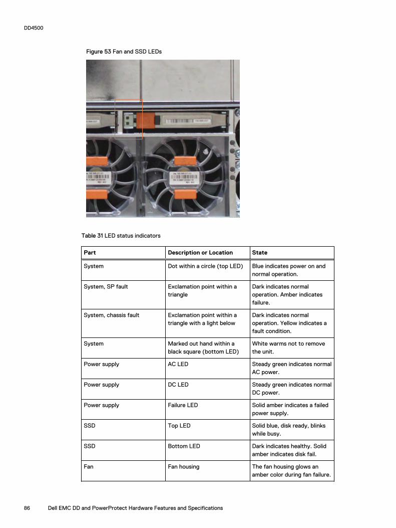
Figure 53 Fan and SSD LEDs
Table 31 LED status indicators
Part Description or Location State
System Dot within a circle (top LED) Blue indicates power on andnormal operation.
System, SP fault Exclamation point within atriangle
Dark indicates normaloperation. Amber indicatesfailure.
System, chassis fault Exclamation point within atriangle with a light below
Dark indicates normaloperation. Yellow indicates afault condition.
System Marked out hand within ablack square (bottom LED)
White warms not to removethe unit.
Power supply AC LED Steady green indicates normalAC power.
Power supply DC LED Steady green indicates normalDC power.
Power supply Failure LED Solid amber indicates a failedpower supply.
SSD Top LED Solid blue, disk ready, blinkswhile busy.
SSD Bottom LED Dark indicates healthy. Solidamber indicates disk fail.
Fan Fan housing The fan housing glows anamber color during fan failure.
DD4500
86 Dell EMC DD and PowerProtect Hardware Features and Specifications
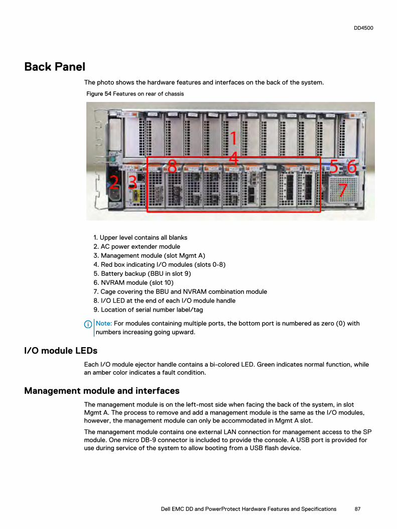
Back PanelThe photo shows the hardware features and interfaces on the back of the system.
Figure 54 Features on rear of chassis
1. Upper level contains all blanks2. AC power extender module3. Management module (slot Mgmt A)4. Red box indicating I/O modules (slots 0-8)5. Battery backup (BBU in slot 9)6. NVRAM module (slot 10)7. Cage covering the BBU and NVRAM combination module8. I/O LED at the end of each I/O module handle9. Location of serial number label/tag
Note: For modules containing multiple ports, the bottom port is numbered as zero (0) withnumbers increasing going upward.
I/O module LEDsEach I/O module ejector handle contains a bi-colored LED. Green indicates normal function, whilean amber color indicates a fault condition.
Management module and interfacesThe management module is on the left-most side when facing the back of the system, in slotMgmt A. The process to remove and add a management module is the same as the I/O modules,however, the management module can only be accommodated in Mgmt A slot.
The management module contains one external LAN connection for management access to the SPmodule. One micro DB-9 connector is included to provide the console. A USB port is provided foruse during service of the system to allow booting from a USB flash device.
DD4500
Dell EMC DD and PowerProtect Hardware Features and Specifications 87

Figure 55 Interfaces on the management module
l 1 - Ethernet port
l 2 - USB port
l 3 - Micro serial port
DD4500
88 Dell EMC DD and PowerProtect Hardware Features and Specifications

I/O modules and slot assignmentsThe table shows the I/O module slot assignments for the systems. See Figure 25 on page 47 for aview of the slot positions on the back panel and Figure 27 on page 51 for a top view.
Table 32 DD4500 slot assignments
Slot Number DD4500 DD4500 with ExtendedRetention Software
DD4500 with DD CloudTier
MGMT A Management module Management module Management module
0 Fibre Channel (FC), Ethernet orempty
FC, Ethernet or empty FC, Ethernet or empty
1 FC, Ethernet or empty FC, Ethernet or empty FC, Ethernet or empty
2 FC, Ethernet or empty FC, Ethernet or empty FC, Ethernet or empty
3 FC, Ethernet or empty FC, Ethernet or empty FC, Ethernet or empty
4 Ethernet or empty Ethernet or empty Ethernet or empty
5 Ethernet or empty SAS Ethernet or empty
6 Empty SAS SAS
7 SAS SAS SAS
8 SAS SAS SAS
9 BBU BBU BBU
10 NVRAM NVRAM NVRAM
Slot addition rulesl A maximum of six optional I/O modules (FC plus Ethernet) are allowed in systems without
Extended Retention software, and a maximum of five optional I/O modules (FC plus Ethernet)are allowed in systems with Extended Retention software.
l Additional FC modules should be installed in numerically increasing slot numbers immediately tothe right of the existing FC modules, or starting in slot 0 if no FC modules were originallyinstalled. A maximum of four FC modules are allowed in a system.
l Additional Ethernet modules should be installed in numerically decreasing slot numbersimmediately to the left of the existing Ethernet modules or starting in slot 4 if no Ethernetmodules were originally installed. For systems without Extended Retention software, amaximum of six (limited to four of any one type) Ethernet modules can be present. Forsystems with Extended Retention software, a maximum of five (limited to four of any onetype) Ethernet modules can be present.
l All systems include two SAS modules in slots 7 and 8. Systems with Extended Retentionsoftware must have two additional SAS modules in slots 5 and 6.
l For systems without Extended Retention software, if adding I/O modules results in the allowedmaximum of six I/O modules present, slot 5 is used. Slot 5 is only used for an Ethernet module.Adding FC modules in this specific case require moving an existing Ethernet module to slot 5.Other than this specific case, it is not recommended to move I/O modules between slots.
DD4500
Dell EMC DD and PowerProtect Hardware Features and Specifications 89

l Adding Extended Retention software to a system includes adding two SAS modules in slots 5and 6. If the system originally had the maximum of 6 optional I/O modules, the I/O module inslot 5 must be permanently removed from the system.
Fibre Channel (FC) I/O Module OptionAn FC I/O module is a dual-port Fibre Channel module. The optional virtual tape library (VTL)feature requires at least one FC I/O module. Boost over Fiber Channel is optional and the total FCHBAs cannot exceed more than allowable Fibre Channel cards per controller.
Ethernet I/O Module OptionsThe available Ethernet I/O modules are:
l Dual Port 10GBase-SR Optical with LC connectors
l Dual Port 10GBase-CX1 Direct Attach Copper with SPF+ module
l Quad Port 1000Base-T Copper with RJ-45 connectors
l Quad port 2 port 1000Base-T Copper (RJ45) /2 port 1000Base-SR Optical
DD4500
90 Dell EMC DD and PowerProtect Hardware Features and Specifications

Internal system componentsThe photo shows the system with the system processor (SP) module that is removed from thechassis and the SP cover removed.
Figure 56 Top view of SP module with SP cover removed
l 1 - Front of system
l 2 - Four groups of 4 DIMM cards
DIMM modulesDD4500 systems contain 8 x 8 GB and 8 x 16 GB of memory DIMM. DIMMs must be in specificslots based on DIMM size.
DD4500 and ES30 shelf guidelines
The Data Domain system rediscovers newly configured shelves after it restarts. You can power offthe system and recable shelves to any other position in a set, or to another set. To take advantageof this flexibility, you need to follow these rules before making any cabling changes:
l Do not exceed the maximum shelf configuration values for your Data Domain system as listedin the following table below.
l Use the Installation and Setup Guide for your Data Domain system to minimize the chance of acabling mistake.
l A Data Domain system cannot exceed its maximum raw external shelf capacity, regardless ofadded shelf capacity.
l ES30 SATA shelves must be on their own chain.
DD4500
Dell EMC DD and PowerProtect Hardware Features and Specifications 91

Note:
l ES30 SAS shelves must be running DD OS 5.4 or later.
l ES30-45 SATA shelves must be running DD OS 5.4 or later.
l DD OS 5.7 and later support 4TB drives.
Table 33 DD4500 and ES30 shelf configuration
DD system Memoryrequired(GB)
SAS cards/port percard
ES30support(TB)
Maxshelvesper set
Maxnumber ofsets
Max externalcapacityavailable (TB)1
Max RAWexternalcapacity(TB) 2
DD4500 192 2x4 SAS 30,45, 60;SATA 15,30, 455
56 4 288 384
DD4500 ER 3, 4 192 4x4 SAS 30,45, 60;SATA 15,30, 455
7 8 576 768
DD4500 w/ DDCloud Tier
192 3x4 SAS 30,45, 60;SATA 15,30, 455
7 8 288 (max),additional 96SAS dedicatedto DD CloudTier
384 (max),additional 120SASdedicated toDD Cloud Tier
1. This figure only counts drives that have user data in the shelves.
2. The raw capacity of an ES30 is 125% of the available capacity.
3. The maximum shelf count for any specific drive/shelf size might be less than the product of max shelves x max shelves per set.
4. With Extended Retention software.
5. ES30-45 (SATA) is only supported with DD OS 5.4 or later.
6. 5 shelves maximum with ES30, 4 is the recommended maximum.
Single phase power connections for 40U-P (current racks)The following figures show single phase power connections for several Data Domain systems.
DD4500
92 Dell EMC DD and PowerProtect Hardware Features and Specifications

Figure 57 Single phase power connections for DD4200, DD4500, and DD7200 systems
DD4500
Dell EMC DD and PowerProtect Hardware Features and Specifications 93
Cabling shelves
Note:
l Before cabling the shelves, physically install all shelves in the racks. Refer to the rail kitinstallation instructions included with the ES30 shelf for rack mounting.
l The documentation refers to two SAS HBAs. If only one HBA is allowed in a system, thenuse another port as defined later for that specific system.
l On an HA system, add cables from the second node to open ports at the end of the sets.The ports on the second node must connect to the same sets as the corresponding portson the first node.
Ports on the system’s SAS HBA cards connect directly to a shelf controller’s host port. Forredundancy, you need to create dual paths by using a port on one SAS HBA card to connect to oneshelf controller in each shelf set, and a port on another SAS HBA card to connect to another shelfcontroller in the same shelf set. With dual paths, if one SAS HBA card fails, the shelf is stilloperational. However, in the unlikely event any single shelf becomes completely disconnected frompower or SAS cables and becomes disconnected from a previously operational shelf, the filesystem goes down and the shelf is not operational. This is considered a double failure.
There are two kinds of configurations: one shelf in a set or multiple shelves in a set.
ES30 and DD4500 cablingThere are a few rules that must be followed when adding a mixture of ES20, ES30 SATA, andES30 SAS shelves to your system. If a system does not follow ALL of these rules it is not alegitimate configuration.
Prerequisites:
l Follow the minimum and maximum shelf capacity configuration provided in the table.
l You cannot have ES20 and ES30 shelves in the same set.
l You cannot have ES30 SATA and ES30 SAS shelves in the same set.
l You cannot exceed the maximum amount of raw capacity displayed in the product's cablingtable.
l The maximum number of shelves displayed in the product's cabling table cannot be exceeded.
l You cannot have more than four ES20s in a single set (maximum preference is three).
l You cannot have more than five ES30s in a single set (maximum preference is four).
l You can have a maximum of seven ES30s for systems with Extended Retention software.
l There are no specific placement or cabling requirements for the metadata shelves for DD CloudTier configurations. These shelves can be installed and cabled the same way as standard ES30shelves.
Note: An ES20 requires more power than an ES30. Ensure that your rack is configured tohandle the power needs.
The tables below show how to configure a mixed system. To use the tables, go to the appropriatesystem. Then find the number of ES20s that are to be configured in the first column. The nextcolumn defines the number of ES20 sets. If there are multiple rows with the same number ofES20s then pick the row with the appropriate number of ES20 SATA shelves. The next column inthat row defines the number of sets of ES30 SATA shelves. Finally, there may be entries for thenumber of desired ES30 SAS shelves and the number of sets to be used.
If the combinations of shelves exceed the supported usable storage, there may not be an entry.The entries are based on the smallest usable storage per shelf type (12TB for ES20, 12 TB for
DD4500
94 Dell EMC DD and PowerProtect Hardware Features and Specifications

ES30 SATA, and 24TB for ES30 SAS). Always check that the sum of the usable storage of all ofthe shelves does not exceed the supported usable storage of the configuration.
Table 34 Minimum and maximum configurations
System Minimumappliance shelfcount
Maximum applianceshelf count
DD Cloud Tiersystems in TB
Extended Retentionsystems (ER) in TB
Max shelvesfor ER
4500(288)
2 20 l 285
l 120 formetadata
l DD OS 5.4 and earlier:1152
l DD OS 5.5 and later:576
40
Systems without Extended Retention or DD Cloud Tier all support four chains. The following tablesshow combinations of ES20 and ES30 shelves. For combinations of any two types of shelves,these tables can be used as a guide.
Table 35 DD4500 cabling information
DD4500
ES20 ES20 chains ES30 SATA ES30 SATAchains
ES30 SAS ES30 SASchains
13-16 4 0 0 0 0
9-12 3 1-5 1 0 0
9-12 3 0 0 1-5 1
5-8 2 1-5 1 1-5 1
5-8 2 6-8 2 0 0
5-8 2 0 0 1-5 1
5-8 2 0 0 6-10 2
1-4 1 9-12 3 0 0
1-4 1 5-8 2 1-5 1
1-4 1 1-4 1 1-5 1
1-4 1 1-4 1 6-10 2
1-4 1 0 0 1-4 1
1-4 1 0 0 5-8 2
1-4 1 0 0 9-11 3
0 0 16-21 4 0 0
0 0 11-15 3 1-5 1
0 0 6-10 2 1-4 1
0 0 6-10 2 5-9 2
0 0 1-5 1 1-4 1
0 0 1-5 1 5-8 2
DD4500
Dell EMC DD and PowerProtect Hardware Features and Specifications 95

Table 35 DD4500 cabling information (continued)
DD4500
0 0 1-5 1 9-11 3
0 0 0 0 1-4 1
0 0 0 0 5-8 2
0 0 0 0 9-12 3
The following figures show cabling for base systems, systems with the Extended Retentionsoftware option, and systems integrated with an Avamar system.
DD4500
96 Dell EMC DD and PowerProtect Hardware Features and Specifications

Figure 58 Recommended DD4500 cabling
DD4500
Dell EMC DD and PowerProtect Hardware Features and Specifications 97

Figure 59 Recommended cabling for DD4500 integrated with Avamar
DD4500
98 Dell EMC DD and PowerProtect Hardware Features and Specifications

Figure 60 Recommended cabling for DD4500 with extended retention software or DD Cloud Tier
DD4500
Dell EMC DD and PowerProtect Hardware Features and Specifications 99

Figure 61 Recommended cabling for DD4500 with extended retention and integrated with Avamar
DD4500 and DS60 shelf guidelines
The Data Domain system rediscovers newly configured shelves after it restarts. You can power offthe system and recable shelves to any other position in a set, or to another set. To take advantageof this flexibility, you need to follow these rules before making any cabling changes:
l Do not exceed the maximum shelf configuration values for your Data Domain system as listedin the following table.
DD4500
100 Dell EMC DD and PowerProtect Hardware Features and Specifications

l For redundancy, the two connections from a Data Domain system to a set of shelves must useports on different SAS I/O modules.
l Use the Installation and Setup Guide for your Data Domain system to minimize the chance of acabling mistake.
l A Data Domain system cannot exceed its maximum raw external shelf capacity, regardless ofadded shelf capacity.
l ES30 SATA shelves must be on their own chain.
l If ES30 SAS shelves are on the same chain as a DS60, the maximum number of shelves on thatchain is 5.
l DD OS 5.7.1 does not support HA with SATA drives.
Table 36 DD4200 and DS60 shelf configuration
DD system Memoryrequired(GB)
SAScards/port percard
DS60 support(TB)
Maxshelvesper set
Maxnumber ofsets
Maxexternalcapacityavailable(TB)1
Max RAWexternalcapacity(TB)
DD4500 192 2x4 SAS 45, 60 2 4 288 360
DD4500 ER 2 192 4x4 SAS 45, 60 2 8 576 720
Note: An entry of 45 corresponds to DS60-3 models and an entry of 60 corresponds toDS60-4 models.
1. This column only counts drives that have user data in the shelves. For example, a DS60 4-240 has 192TB.
2. With Extended Retention software.
Single phase power connections for 40U-P (current racks)The following figures show single phase power connections for several Data Domain systems.
DD4500
Dell EMC DD and PowerProtect Hardware Features and Specifications 101

Figure 62 Single phase power connections for DD4200, DD4500, and DD7200 systems
DD4500
102 Dell EMC DD and PowerProtect Hardware Features and Specifications

3-phase power connections for 40U-P (current racks)Some environments use 3-phase power for 40U-P racks used for several Data Domain systems. Inthose situations it is desirable to balance the current draw across all 3 phases. The recommended3-phase power cabling attempts to do that, but an optimal configuration is dependent on thespecific installation. The following figures show recommended 3-phase power connections forseveral Data Domain systems.
Note: The next few diagrams show recommended 3-phase delta power connections.
DD4500
Dell EMC DD and PowerProtect Hardware Features and Specifications 103

Figure 63 3-phase delta power connections for DS60 expansion shelves (full-racked)
DD4500
104 Dell EMC DD and PowerProtect Hardware Features and Specifications

Figure 64 3-phase delta power connections for DD4200, DD4500, and DD7200 systems
Note: The next few diagrams show recommended 3-phase wye power connections.
DD4500
Dell EMC DD and PowerProtect Hardware Features and Specifications 105

Figure 65 3-phase wye power connections for DS60 expansion shelves (full-racked)
DD4500
106 Dell EMC DD and PowerProtect Hardware Features and Specifications

Figure 66 3-phase wye power connections for DD4200, DD4500, and DD7200 systems
DD4500
Dell EMC DD and PowerProtect Hardware Features and Specifications 107

DS60 and DD4500 cablingThere are a few rules that must be followed when adding a mixture of DS60 and other shelf typesto your system.
CAUTION If a system does not follow all these rules, it is not a legitimate configuration.
Prerequisites:
l You cannot exceed the maximum amount of usable capacity displayed in cabling table for eachsystem.
l You cannot exceed the maximum number of shelves displayed in cabling table for each system.
l You cannot connect more than two DS60 shelves in a single set.
Table 37 Minimum and maximum configurations
System Appliance maximum Minimum appliance shelf count
DD4500 288 TB 1
Mixing DS60, ES30, and ES20 shelves:
The non-Extended Retention versions of these systems all support four chains.
Extra planning and reconfiguration may be required to add DS60 shelves to system with ES20shelves, ES30 SATA shelves, or a combination of shelves.
l The ES20 shelves must be on their own set. Minimize the ES20 set count by combining up tofour ES20s per set.
l ES30 SATA shelves must also be on their own sets. Minimize the ES30 set count by combiningup to five ES30s per set. If required, combine up to seven ES30 SAS shelves per set tominimize the set count.
l A set can contain a maximum of two DS60 shelves and, if required because of otherrestrictions, add ES30 SAS shelves up to a maximum of five shelves in that set.
Note: The configuration rules apply also to Extended Retention systems.
The following figures show cabling for base systems and systems with the Extended Retentionsoftware.
Note: It is recommended that the DS60 shelf with the greater number of drives should alwaysbe placed in the bottom position.
DD4500
108 Dell EMC DD and PowerProtect Hardware Features and Specifications

Figure 67 Recommended cabling for DD4500 (3TB drives)
DD4500
Dell EMC DD and PowerProtect Hardware Features and Specifications 109

Figure 68 Recommended cabling for DD4500 (3TB drives) with Extended Retention software
DD4500
110 Dell EMC DD and PowerProtect Hardware Features and Specifications
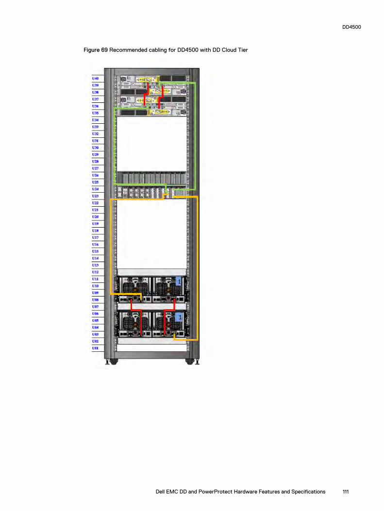
Figure 69 Recommended cabling for DD4500 with DD Cloud Tier
DD4500
Dell EMC DD and PowerProtect Hardware Features and Specifications 111

Figure 70 Recommended cabling for DD4500 (4TB drives)
Note: DS60 shelf 2 will only have 30 drives.
DD4500
112 Dell EMC DD and PowerProtect Hardware Features and Specifications

Figure 71 Recommended cabling for DD4500 (4TB drives) with Extended Retention software
Note: All three of the DS60 shelves will be full.
DD4500
Dell EMC DD and PowerProtect Hardware Features and Specifications 113

DD4500
114 Dell EMC DD and PowerProtect Hardware Features and Specifications

CHAPTER 4
DD6300
This chapter contains the following topics:
l DD6300 system features...................................................................................................... 116l DD6300 system specifications..............................................................................................117l DD6300 storage capacity..................................................................................................... 117l DD6300 front panel.............................................................................................................. 118l Back panel............................................................................................................................ 121l I/O modules......................................................................................................................... 124l Internal system components................................................................................................ 127l DD6300 and ES30 shelf guidelines.......................................................................................128l DD6300 and DS60 shelf guidelines...................................................................................... 130
Dell EMC DD and PowerProtect Hardware Features and Specifications 115

DD6300 system features
Table 38 DD6300 system features
Feature Baseconfiguration
Expandedconfiguration
Rack height 2U 2U
Processor E5-2620 V3 E5-2620 V3
Kernel 3.2.x 3.2.x
NVRAM
Memory 6 x 8 GB DIMM (48GB)
12 x 8 GB DIMM(96 GB)
Internal drives HDDs in 3.5" bays 7/ 7+5 12
SSDs in 3.5" bays 0 0
SSDs in 2.5" bays 1 2
I/O module slots SAS I/O modules () l 0 for internalstorage only
l 1 with externalstorage
l 0 for internalstorage only
l 1 with externalstorage
Network and FC I/O modules Four replaceableI/O module slots.Not hot-swappable.
Four replaceableI/O module slots.Not hot-swappable.
Supported capacity 76 TB (28 TBinternal + 48 TBexternal)
180 TB (36 TBinternal + 144 TBexternal)
High availability support No No
HA private interconnect N/A N/A
External SSD shelf N/A N/A
SAS string depth(max)
ES30 1 4
DS60 0 1
Stream count 270 writes, 75reads
270 writes, 75reads
DD6300
116 Dell EMC DD and PowerProtect Hardware Features and Specifications
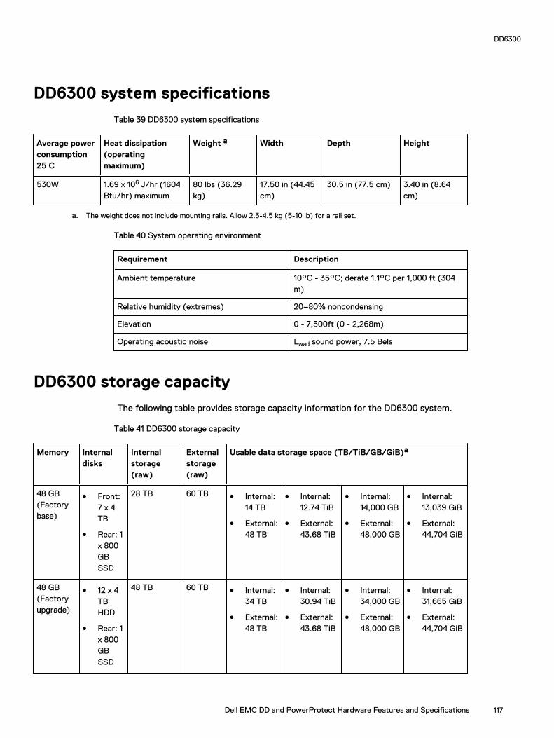
DD6300 system specifications
Table 39 DD6300 system specifications
Average powerconsumption25 C
Heat dissipation(operatingmaximum)
Weight a Width Depth Height
530W 1.69 x 10⁶ J/hr (1604Btu/hr) maximum
80 lbs (36.29kg)
17.50 in (44.45cm)
30.5 in (77.5 cm) 3.40 in (8.64cm)
a. The weight does not include mounting rails. Allow 2.3-4.5 kg (5-10 lb) for a rail set.
Table 40 System operating environment
Requirement Description
Ambient temperature 10°C - 35°C; derate 1.1°C per 1,000 ft (304m)
Relative humidity (extremes) 20–80% noncondensing
Elevation 0 - 7,500ft (0 - 2,268m)
Operating acoustic noise Lwad sound power, 7.5 Bels
DD6300 storage capacity
The following table provides storage capacity information for the DD6300 system.
Table 41 DD6300 storage capacity
Memory Internaldisks
Internalstorage(raw)
Externalstorage(raw)
Usable data storage space (TB/TiB/GB/GiB)a
48 GB(Factorybase)
l Front:7 x 4TB
l Rear: 1x 800GBSSD
28 TB 60 TB l Internal:14 TB
l External:48 TB
l Internal:12.74 TiB
l External:43.68 TiB
l Internal:14,000 GB
l External:48,000 GB
l Internal:13,039 GiB
l External:44,704 GiB
48 GB(Factoryupgrade)
l 12 x 4TBHDD
l Rear: 1x 800GBSSD
48 TB 60 TB l Internal:34 TB
l External:48 TB
l Internal:30.94 TiB
l External:43.68 TiB
l Internal:34,000 GB
l External:48,000 GB
l Internal:31,665 GiB
l External:44,704 GiB
DD6300
Dell EMC DD and PowerProtect Hardware Features and Specifications 117

Table 41 DD6300 storage capacity (continued)
Memory Internaldisks
Internalstorage(raw)
Externalstorage(raw)
Usable data storage space (TB/TiB/GB/GiB)a
48 GB(FieldUpgrade)
l (7 + 5)x 4 TBHDD
l Rear: 1x 800GBSSD
48 TB 60 TB l Internal:22 TB
l External:48 TB
l Internal:20.02 TiB
l External:43.68 TiB
l Internal:22,000 GB
l External:48,000 GB
l Internal:20,489 GiB
l External:44,704 GiB
96 GB(Expanded)
l Front:12 x 4TBHDDs
l Rear: 2x 800GBSSD
48 TB 180 TB l Internal:34 TB
l External:144 TB
l Internal:30.94 TiB
l External:131 TiB
l Internal:34,000 GB
l External:144,000GB
l Internal:31,665 GiB
l External:134,110 GiB
96 GB(Fieldupgradefrom 48GB)
l Front:(7 + 5)x 4 TBHDDs
l Rear: 2x 800GBSSD
48 TB 180 TB l Internal:22 TB
l External:144 TB
l Internal:20.02 TiB
l External:131 TiB
l Internal:22,000 GB
l External:144,000GB
l Internal:20,489 GiB
l External:134,110 GiB
a. The capacity differs depending on the size of the external storage shelves used. This data based on ES30 shelves.
DD6300 front panel
DD6300 All-in-One (AIO) systems have one of the following front panel drive configurations tohost the DD OS boot drives, and provide storage for customer data:
Note: Upgrading a base configuration to an expanded configuration provides less capacity thana factory-built expanded configuration.
Table 42 DD6300 AIO capacity
Configuration Installed drives Usable internal capacity
DD6300 baseconfiguration
Seven 4 TB HDDs 14 TB
DD6300 expandedconfiguration (factory)
Twelve 4 TB HDDs 34 TB
DD6300
118 Dell EMC DD and PowerProtect Hardware Features and Specifications

Table 42 DD6300 AIO capacity (continued)
Configuration Installed drives Usable internal capacity
DD6300 expandedconfiguration (upgrade)
Seven 4 TB HDDs + Five 4 TB HDDs 22 TB
Table 43 DD6300 AIO configuration
Slot 0: HDD 1 Slot 1: HDD 2 Slot 2: HDD 3 Slot 3: HDD 4
Slot 4: HDD 5 Slot 5: HDD 6 Slot 6: HDD 7 Slot 7: Filler
Slot 8: Filler Slot 9: Filler Slot 10: Filler Slot 11: Filler
Table 44 DD6300 AIO expanded configuration
Slot 0: HDD 1 Slot 1: HDD 2 Slot 2: HDD 3 Slot 3: HDD 4
Slot 4: HDD 5 Slot 5: HDD 6 Slot 6: HDD 7 Slot 7: HDD 8
Slot 8: HDD 9 Slot 9: HDD 10 Slot 10: HDD 11 Slot 11: HDD 12
Front LED indicatorsThe front of the system contain 12 disk drive status LEDs that are normally blue, and blink whenthere is activity on the disk. The LEDs are shaped like triangles, and the apex of the triangle pointsleft or right, indicating that disk's status. If the disk drive has a failure, the disk’s status LED turnsfrom blue to amber, indicating that a drive must be replaced.
The front also contains two system status LEDs. A blue system power LED is present that is onwhenever the system has power. An amber system fault LED is also present that is normally offand lit amber whenever the chassis or any other FRU in the system requires service.
Figure 72 Front LED indicators
1. System service LED2. Drive activity/service LED3. System power LED
Table 45 Front LEDs
Name Color Purpose
System power LED Blue Indication that the system haspower.
DD6300
Dell EMC DD and PowerProtect Hardware Features and Specifications 119
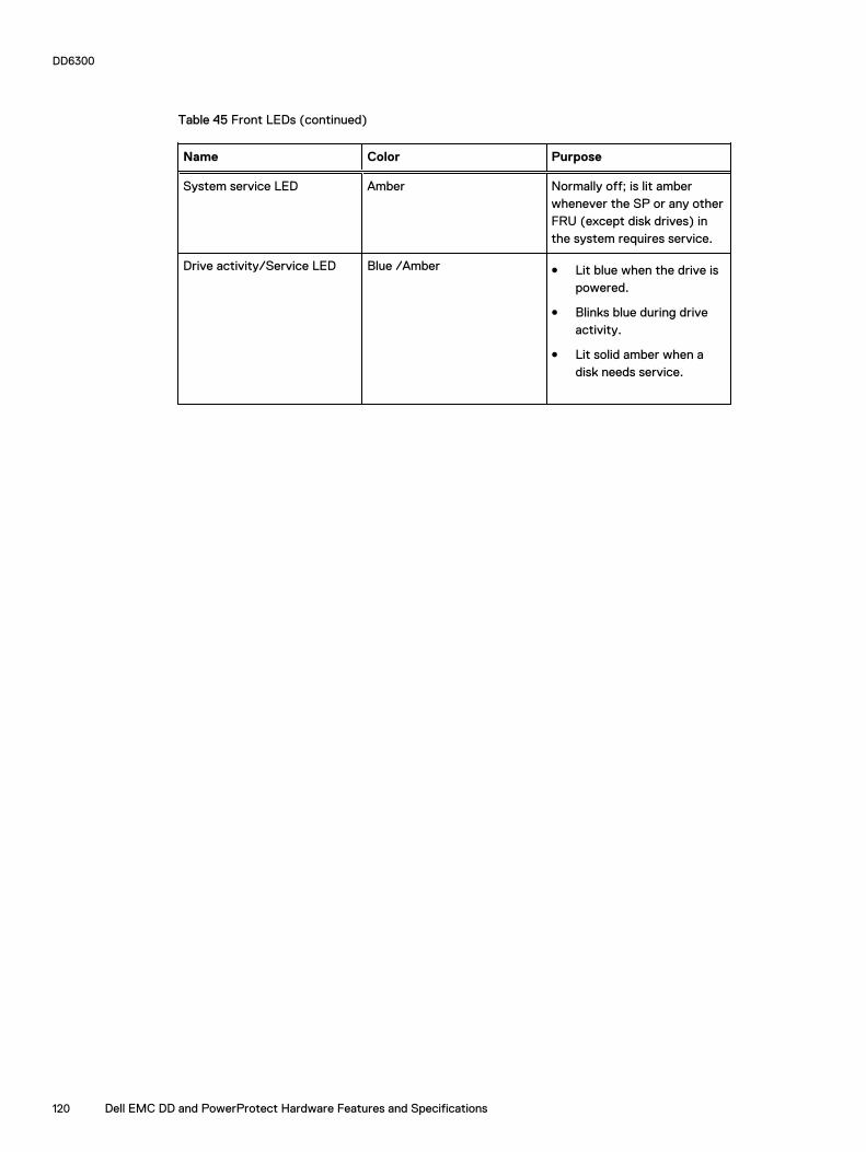
Table 45 Front LEDs (continued)
Name Color Purpose
System service LED Amber Normally off; is lit amberwhenever the SP or any otherFRU (except disk drives) inthe system requires service.
Drive activity/Service LED Blue /Amber l Lit blue when the drive ispowered.
l Blinks blue during driveactivity.
l Lit solid amber when adisk needs service.
DD6300
120 Dell EMC DD and PowerProtect Hardware Features and Specifications

Back panelThe back panel of the chassis contains the following components:
1. Management panel
2. Two 2.5" SSD slots labeled 0 and 1
3. I/O module slots
4. Power supply modules (PSU 0 is the lower module, and PSU 1 is the upper module)
DD6300 rear SSDsThe D6300 system uses one or two 800 GB SSDs mounted at the rear of the chassis for metadatacaching:
Table 46 DD6300 rear SSDs
Configuration Number of SSDs SSD location
DD6300 1 SSD slot 0
DD6300 expanded 2 SSD slots 0 and 1
Note: SSDs are not RAID-protected.
Rear LED indicatorsFigure 73 Rear LED indicators
1. Do not remove LED2. SP service LED3. System power LED4. AC power good LED5. DC power good LED6. Power supply fault LED
DD6300
Dell EMC DD and PowerProtect Hardware Features and Specifications 121
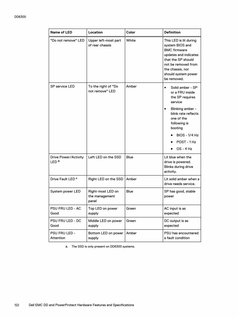
Name of LED Location Color Definition
"Do not remove" LED Upper left-most partof rear chassis
White This LED is lit duringsystem BIOS andBMC firmwareupdates and indicatesthat the SP shouldnot be removed fromthe chassis, norshould system powerbe removed.
SP service LED To the right of "Donot remove" LED
Amber l Solid amber - SPor a FRU insidethe SP requiresservice
l Blinking amber -blink rate reflectsone of thefollowing isbooting
n BIOS - 1/4 Hz
n POST - 1 Hz
n OS - 4 Hz
Drive Power/ActivityLED a
Left LED on the SSD Blue Lit blue when thedrive is powered.Blinks during driveactivity.
Drive Fault LED a Right LED on the SSD Amber Lit solid amber when adrive needs service.
System power LED Right-most LED onthe managementpanel
Blue SP has good, stablepower
PSU FRU LED - ACGood
Top LED on powersupply
Green AC input is asexpected
PSU FRU LED - DCGood
Middle LED on powersupply
Green DC output is asexpected
PSU FRU LED -Attention
Bottom LED on powersupply
Amber PSU has encountereda fault condition
a. The SSD is only present on DD6300 systems.
DD6300
122 Dell EMC DD and PowerProtect Hardware Features and Specifications

Figure 74 I/O module Power/Service LED location
1. I/O module power/service LED
Table 47 I/O LEDs
Name of LED Location Color Definition
I/O module FRU LED- Figure 74 on page123
Ejector handle of I/Omodules
Green/Amber l Green - I/Omodule has powerand is functioningnormally
l Amber - I/Omodule hasencountered afault conditionand requiresservice
I/O port status LED(SAS, Fibre Channel,and opticalnetworking I/Omodules only)
One LED per I/Omodule port
Blue Lit when port isenabled. May flash ifSW "marks" theport. a
DD6300
Dell EMC DD and PowerProtect Hardware Features and Specifications 123

Table 47 I/O LEDs (continued)
a. For RJ45 networking ports, the standard green link and amber activity LEDs are used.
Figure 75 Onboard network port LEDs
1. Network port link LED2. Network port activity LED3. Dedicated IPMI port BMC0A4. Management interface EthMa
Table 48 Onboard network port LEDs
Name of LED Location Color Definition
Onboard network portLED - Link LED Figure75 on page 124
Top LED on networkport
Green l Lit when there isa link at1000BaseT and100BaseT speeds
l Off when the linkspeed is 10BaseTor there is no link
Onboard network portLED - Activity LED
Bottom LED onnetwork port
Amber Blinks when there istraffic on the port
I/O modulesI/O module slot numbering
The eight I/O module slots are enumerated as Slot 0 (on the left when viewed from the rear)through Slot 7. Ports on an I/O module are enumerated as 0 through 3, with 0 being on thebottom.
Figure 76 I/O module slot numbering
DD6300
124 Dell EMC DD and PowerProtect Hardware Features and Specifications
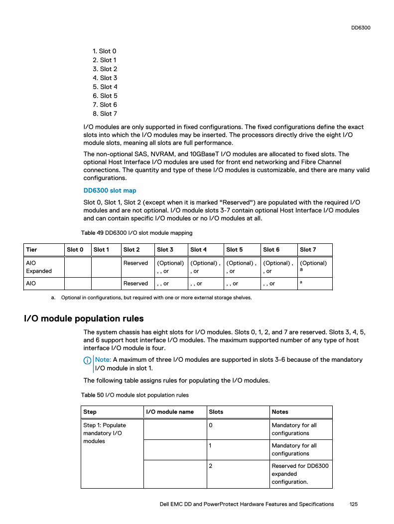
1. Slot 02. Slot 13. Slot 24. Slot 35. Slot 46. Slot 57. Slot 68. Slot 7
I/O modules are only supported in fixed configurations. The fixed configurations define the exactslots into which the I/O modules may be inserted. The processors directly drive the eight I/Omodule slots, meaning all slots are full performance.
The non-optional SAS, NVRAM, and 10GBaseT I/O modules are allocated to fixed slots. Theoptional Host Interface I/O modules are used for front end networking and Fibre Channelconnections. The quantity and type of these I/O modules is customizable, and there are many validconfigurations.
DD6300 slot map
Slot 0, Slot 1, Slot 2 (except when it is marked "Reserved") are populated with the required I/Omodules and are not optional. I/O module slots 3-7 contain optional Host Interface I/O modulesand can contain specific I/O modules or no I/O modules at all.
Table 49 DD6300 I/O slot module mapping
Tier Slot 0 Slot 1 Slot 2 Slot 3 Slot 4 Slot 5 Slot 6 Slot 7
AIOExpanded
Reserved (Optional) , , or
(Optional) , , or
(Optional) , , or
(Optional) , , or
(Optional)a
AIO Reserved , , or , , or , , or , , or a
a. Optional in configurations, but required with one or more external storage shelves.
I/O module population rulesThe system chassis has eight slots for I/O modules. Slots 0, 1, 2, and 7 are reserved. Slots 3, 4, 5,and 6 support host interface I/O modules. The maximum supported number of any type of hostinterface I/O module is four.
Note: A maximum of three I/O modules are supported in slots 3-6 because of the mandatory I/O module in slot 1.
The following table assigns rules for populating the I/O modules.
Table 50 I/O module slot population rules
Step I/O module name Slots Notes
Step 1: Populatemandatory I/Omodules
0 Mandatory for allconfigurations
1 Mandatory for allconfigurations
2 Reserved for DD6300expandedconfiguration.
DD6300
Dell EMC DD and PowerProtect Hardware Features and Specifications 125

Table 50 I/O module slot population rules (continued)
Step I/O module name Slots Notes
7 Reserved for DD6300base configuration.
Step 2: Populate all I/O modules
3, 4, 5, 6 Populate startingfrom the lowestavailable slot number.
Step 3: Populate all I/O modules
3, 4, 5, 6 Populate startingfrom the lowestavailable slot number.With in slot 1, maxnumber of I/Omodules are limited to4.
Step 4: Populate all I/O modules
6, 5, 4, 3 Populate startingfrom the highestavailable slot number.
DD6300
126 Dell EMC DD and PowerProtect Hardware Features and Specifications

Internal system componentsThe following figure shows the layout of the CPUs and DIMMs inside the chassis. The front of thesystem is at the top of the figure.
Figure 77 CPU and memory locations
DIMMs overviewDual in-line memory modules (DIMM) come in various sizes, which must be configured in a certainway. This topic can help you select the correct configuration when servicing DIMMs.
The storage processor contains two Intel processors each with an integrated memory controllerthat supports four channels of memory. The storage processor allows two DIMM slots per channel,so the storage processor supports a total of 16 DIMM slots.
DD6300 memory DIMM configuration
Table 51 DD6300 memory DIMM configuration
Tier Total Memory Memory DIMM Configuration
AIO Expanded 96 GB 12 x 8 GB
AIO 48 GB 6 x 8 GB
To ensure maximum memory performance, there are memory DIMM population rules for bestmemory loading and interleaving. Table 52 on page 127 and Table 53 on page 127 specify theDIMM location rules for various memory configurations:
Table 52 Memory locations - CPU 0
Channel A Channel B Channel D Channel C
Tier TotalMemory
0 1 2 3 4 5 6 7
AIOExpanded
96 GB 8 GB N/A 8 GB N/A 8 GB 8 GB 8 GB 8 GB
AIO 48 GB N/A N/A 8 GB N/A N/A 8 GB N/A 8 GB
Table 53 Memory locations - CPU 1
Channel A Channel B Channel D Channel C
DD6300
Dell EMC DD and PowerProtect Hardware Features and Specifications 127

Table 53 Memory locations - CPU 1 (continued)
Tier TotalMemory
8 9 10 11 12 13 14 15
AIOExpanded
96 GB 8 GB 8 GB 8 GB 8 GB N/A 8 GB N/A 8 GB
AIO 48 GB 8 GB N/A 8 GB N/A N/A 8 GB N/A N/A
DD6300 and ES30 shelf guidelines
The system rediscovers newly configured shelves after it restarts. You can power off the systemand recable shelves to any other position in a set, or to another set. To take advantage of thisflexibility, you need to follow these rules before making any cabling changes:
l Do not exceed the maximum shelf configuration values for your system as listed in thefollowing table below.
l Use the Installation and Setup Guide for your system to minimize the chance of a cablingmistake.
l A system cannot exceed its maximum raw external shelf capacity, regardless of added shelfcapacity.
l ES30 SATA shelves must be on their own chain.
Table 54 DD6300 and ES30 shelf configuration
DD system Memoryrequired(GB)
SAS cards/port percard
ES30support(TB)
Maxshelvesper set
Maxnumber ofsets
Max externalcapacityavailable (TB)1
Max RAWexternalcapacity(TB) 2
DD6300 48 1x4(Optional)
SAS 30,45, 60
1 1 48 60
DD6300 w/ExpandedCapacity 3
96 1x4(Optional)
SAS 30,45, 60
5 1 144 180
1. This figure only counts drives that have user data in the shelves.
2. The raw capacity of an ES30 is 125% of the available capacity.
3. DDOS 6.0 and FS15 SSD shelf configuration
Types of cabinets and power connectionsThe ES30 chassis is installed in two types of racks: 40U-C (existing racks) and the 40U-P (newerracks). The racks use one phase or 3-phase power connections.
3-Phase power connections for 40U-P (current racks)
Some environments use 3-phase power for 40U-P racks that are used for several systems. Inthose situations, it is desirable to balance the current draw across all three phases. Therecommended 3-phase power cabling attempts to do that, but an optimal configuration dependson the specific installation.
DD6300
128 Dell EMC DD and PowerProtect Hardware Features and Specifications
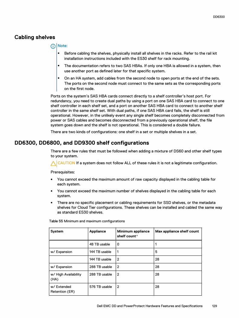
Cabling shelves
Note:
l Before cabling the shelves, physically install all shelves in the racks. Refer to the rail kitinstallation instructions included with the ES30 shelf for rack mounting.
l The documentation refers to two SAS HBAs. If only one HBA is allowed in a system, thenuse another port as defined later for that specific system.
l On an HA system, add cables from the second node to open ports at the end of the sets.The ports on the second node must connect to the same sets as the corresponding portson the first node.
Ports on the system’s SAS HBA cards connect directly to a shelf controller’s host port. Forredundancy, you need to create dual paths by using a port on one SAS HBA card to connect to oneshelf controller in each shelf set, and a port on another SAS HBA card to connect to another shelfcontroller in the same shelf set. With dual paths, if one SAS HBA card fails, the shelf is stilloperational. However, in the unlikely event any single shelf becomes completely disconnected frompower or SAS cables and becomes disconnected from a previously operational shelf, the filesystem goes down and the shelf is not operational. This is considered a double failure.
There are two kinds of configurations: one shelf in a set or multiple shelves in a set.
DD6300, DD6800, and DD9300 shelf configurationsThere are a few rules that must be followed when adding a mixture of DS60 and other shelf typesto your system.
CAUTION If a system does not follow ALL of these rules it is not a legitimate configuration.
Prerequisites:
l You cannot exceed the maximum amount of raw capacity displayed in the cabling table foreach system.
l You cannot exceed the maximum number of shelves displayed in the cabling table for eachsystem.
l There are no specific placement or cabling requirements for SSD shelves, or the metadatashelves for Cloud Tier configurations. These shelves can be installed and cabled the same wayas standard ES30 shelves.
Table 55 Minimum and maximum configurations
System Appliance Minimum applianceshelf count*
Max appliance shelf count
48 TB usable 0 1
w/ Expansion 144 TB usable 1 5
144 TB usable 2 28
w/ Expansion 288 TB usable 2 28
w/ High Availability(HA)
288 TB usable 2 28
w/ ExtendedRetention (ER)
576 TB usable 2 28
DD6300
Dell EMC DD and PowerProtect Hardware Features and Specifications 129

Table 55 Minimum and maximum configurations (continued)
System Appliance Minimum applianceshelf count*
Max appliance shelf count
w/ Cloud Tier 288 TB usable(96 TB forCloud Tier)
2 28
w/ HA and Cloud Tier 288 TB usable(96 TB forCloud Tier)
2 28
384 TB usable 3 28
w/ Expansion 720 TB usable 3 28
w/ HA 720 TB usable 3 28
w/ ER 1440 TB usable 7 28
w/ Cloud Tier 720 TB usable(192 TB forCloud Tier)
7 28
w/ HA and Cloud Tier 720 TB usable(192 TB forCloud Tier)
7 28
* The minimum appliance shelf count does not include shelves for Cloud Tier.
DD6300 and DS60 shelf guidelines
The system rediscovers newly configured shelves after it restarts. You can power off the systemand recable shelves to any other position in a set, or to another set. To take advantage of thisflexibility, you need to follow these rules before making any cabling changes:
l Do not exceed the maximum shelf configuration values for your system as listed in thefollowing table.
l For redundancy, the two connections from a system to a set of shelves must use ports ondifferent SAS I/O modules.
l Use the Installation and Setup Guide for your system to minimize the chance of a cablingmistake.
l A system cannot exceed its maximum raw external shelf capacity, regardless of added shelfcapacity.
l ES30 SATA shelves must be on their own chain.
l If ES30 SAS shelves are on the same chain as a DS60, the maximum number of shelves on thatchain is 5.
DD6300
130 Dell EMC DD and PowerProtect Hardware Features and Specifications
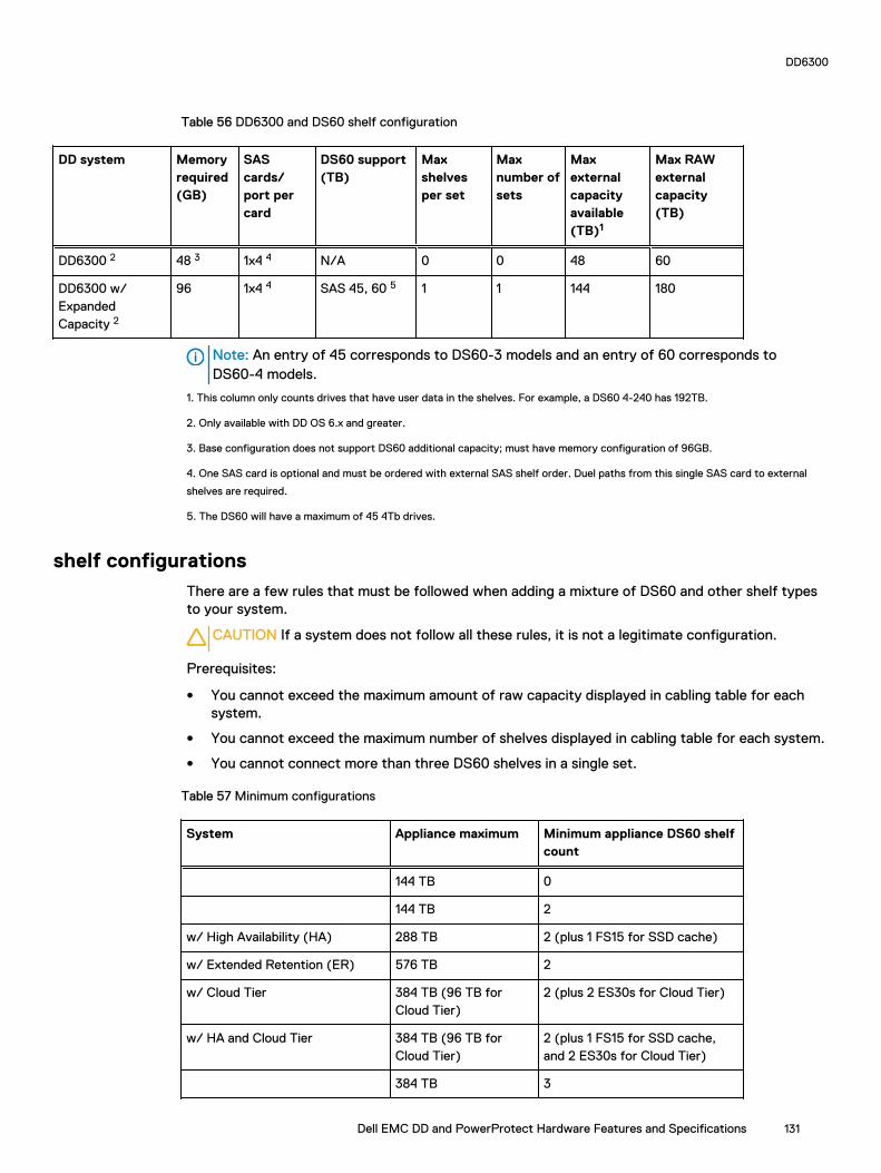
Table 56 DD6300 and DS60 shelf configuration
DD system Memoryrequired(GB)
SAScards/port percard
DS60 support(TB)
Maxshelvesper set
Maxnumber ofsets
Maxexternalcapacityavailable(TB)1
Max RAWexternalcapacity(TB)
DD6300 2 48 3 1x4 4 N/A 0 0 48 60
DD6300 w/ExpandedCapacity 2
96 1x4 4 SAS 45, 60 5 1 1 144 180
Note: An entry of 45 corresponds to DS60-3 models and an entry of 60 corresponds toDS60-4 models.
1. This column only counts drives that have user data in the shelves. For example, a DS60 4-240 has 192TB.
2. Only available with DD OS 6.x and greater.
3. Base configuration does not support DS60 additional capacity; must have memory configuration of 96GB.
4. One SAS card is optional and must be ordered with external SAS shelf order. Duel paths from this single SAS card to external
shelves are required.
5. The DS60 will have a maximum of 45 4Tb drives.
shelf configurationsThere are a few rules that must be followed when adding a mixture of DS60 and other shelf typesto your system.
CAUTION If a system does not follow all these rules, it is not a legitimate configuration.
Prerequisites:
l You cannot exceed the maximum amount of raw capacity displayed in cabling table for eachsystem.
l You cannot exceed the maximum number of shelves displayed in cabling table for each system.
l You cannot connect more than three DS60 shelves in a single set.
Table 57 Minimum configurations
System Appliance maximum Minimum appliance DS60 shelfcount
144 TB 0
144 TB 2
w/ High Availability (HA) 288 TB 2 (plus 1 FS15 for SSD cache)
w/ Extended Retention (ER) 576 TB 2
w/ Cloud Tier 384 TB (96 TB forCloud Tier)
2 (plus 2 ES30s for Cloud Tier)
w/ HA and Cloud Tier 384 TB (96 TB forCloud Tier)
2 (plus 1 FS15 for SSD cache,and 2 ES30s for Cloud Tier)
384 TB 3
DD6300
Dell EMC DD and PowerProtect Hardware Features and Specifications 131

Table 57 Minimum configurations (continued)
System Appliance maximum Minimum appliance DS60 shelfcount
w/ HA 720 TB 3 (plus 1 FS15 for SSD cache)
w/ ER 1440 TB 3
w/ Cloud Tier 912 TB (192 TB forCloud Tier)
3 (plus 4 ES30s or 1 DS60 forCloud Tier)
w/ HA and Cloud Tier 912 TB (192 TB forCloud Tier)
4 (plus 1 FS15 for SSD cache,and 4 ES30s or 1 DS60 for CloudTier)
1. DS60 will only be partially filled.
l A Cloud Tier system shares the ERSO cabling configuration; however, Cloud Tier has a lowermaximum.
l It is recommended that the shelf with the greater number of drives should always be placed inthe bottom position.
l only supports one DS60.
l only has one SAS SLIC and all DS60 connections are made to that single SAS SLIC.
l only has one SAS SLIC and all DS60 connections are made to that single SAS SLIC.
DD6300
132 Dell EMC DD and PowerProtect Hardware Features and Specifications

CHAPTER 5
DD6800
This chapter contains the following topics:
l DD6800 system features..................................................................................................... 134l DD6800 system specifications.............................................................................................135l DD6800 storage capacity.................................................................................................... 135l DD6800 front panel............................................................................................................. 136l Back panel........................................................................................................................... 138l I/O modules..........................................................................................................................141l Internal system components................................................................................................ 144l DD6800 and ES30 shelf guidelines.......................................................................................145l DD6800 and DS60 shelf guidelines...................................................................................... 148
Dell EMC DD and PowerProtect Hardware Features and Specifications 133

DD6800 system features
Table 58 DD6800 system features
Feature Baseconfiguration
Expandedconfiguration
Rack height 2U 2U
Processor E5-2630 V3 E5-2630 V3
Kernel 3.2.x 3.2.x
NVRAM
Memory 8 x 8 GB DIMM + 8x 16 GB DIMM (192GB)
8 x 8 GB DIMM + 8x 16 GB DIMM (192GB)
Internal drives HDDs in 3.5" bays 7/ 7+5 12
SSDs in 3.5" bays 0 0
SSDs in 2.5" bays 1 2
I/O module slots SAS I/O modules () 2 2
Network and FC I/O modules Four replaceableI/O module slots.Not hot-swappable.
Four replaceableI/O module slots.Not hot-swappable.
Supported capacity Non-extended retention 144 TB 288 TB
DD Cloud Tier N/A 576 TB a
Extended retention N/A 288 TBb
High availability support Yes Yes
HA private interconnect (2) 10GBase-Tports
(2) 10GBase-Tports
External SSD shelf One SSD shelf forA-P highavailability clustercontaining twodrives.
One SSD shelf forA-P highavailability clustercontaining fourdrives.
SAS string depth(max)
ES30 1 4
DS60 0 1
ES30 and DS60 5 shelves total 5 shelves total
Stream count 405 writes, 112reads
405 writes, 112reads
a. DD Cloud Tier requires two ES30 shelves fully populated with 4 TB drives to store DD CloudTier metadata.
b. Extended retention not available on HA configurations
DD6800
134 Dell EMC DD and PowerProtect Hardware Features and Specifications
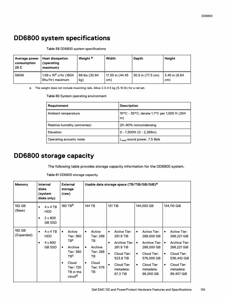
DD6800 system specifications
Table 59 DD6800 system specifications
Average powerconsumption25 C
Heat dissipation(operatingmaximum)
Weight a Width Depth Height
560W 1.69 x 10⁶ J/hr (1604Btu/hr) maximum
68 lbs (30.84kg)
17.50 in (44.45cm)
30.5 in (77.5 cm) 3.40 in (8.64cm)
a. The weight does not include mounting rails. Allow 2.3-4.5 kg (5-10 lb) for a rail set.
Table 60 System operating environment
Requirement Description
Ambient temperature 10°C - 35°C; derate 1.1°C per 1,000 ft (304m)
Relative humidity (extremes) 20–80% noncondensing
Elevation 0 - 7,500ft (0 - 2,268m)
Operating acoustic noise Lwad sound power, 7.5 Bels
DD6800 storage capacity
The following table provides storage capacity information for the DD6800 system.
Table 61 DD6800 storage capacity
Memory Internaldisks(systemdisks only)
Externalstorage(raw)
Usable data storage space (TB/TiB/GB/GiB)a
192 GB(Base)
l 4 x 4 TBHDD
l 2 x 800GB SSD
180 TBb 144 TB 131 TiB 144,000 GB 134,110 GiB
192 GB(Expanded)
l 4 x 4 TBHDD
l 4 x 800GB SSD
l ActiveTier: 360TBb
l ArchiveTier: 360TBc
l CloudTier: 720TB in thecloudd
l ActiveTier: 288TB
l ArchiveTier: 288TB
l CloudTier: 576TB
l Active Tier:261.9 TiB
l Archive Tier:261.9 TiB
l Cloud Tier:523.8 TiB
l Cloud Tiermetadata:87.3 TiB
l Active Tier:288,000 GB
l Archive Tier:288,000 GB
l Cloud Tier:576,000 GB
l Cloud Tiermetadata:96,000 GB
l Active Tier:268,221 GiB
l Archive Tier:268,221 GiB
l Cloud Tier:536,442 GiB
l Cloud Tiermetadata:89,407 GiB
DD6800
Dell EMC DD and PowerProtect Hardware Features and Specifications 135

Table 61 DD6800 storage capacity (continued)
Memory Internaldisks(systemdisks only)
Externalstorage(raw)
Usable data storage space (TB/TiB/GB/GiB)a
l CloudTiermetadata: 120 TBlocalstorage
l CloudTiermetadata: 96 TB
a. The capacity differs depending on the size of the external storage shelves used. This data based on ES30 shelves.b. HA is supported.c. HA is not supported with Extended Retention.d. HA is supported in combination with Cloud Tier.
DD6800 front panel
DD6800 Dataless Head (DLH) systems have one of the following front panel drive configurationsto host the DD OS boot drives and provide metadata caching on SSD:
Table 62 DD6800 DLH SSD requirements
Configuration Number of SSDs
DD6800 2
DD6800 expanded 4
Note: SSDs are not RAID-protected.
Table 63 DD6800 DLH configuration drive layout
Slot 0: HDD 1 Slot 1: HDD 2 Slot 2: HDD 3 Slot 3: HDD 4
Slot 4: SSD 1 Slot 5: SSD 2 Slot 6: Filler Slot 7: Filler
Slot 8: Filler Slot 9: Filler Slot 10: Filler Slot 11: Filler
Table 64 DD6800 DLH expanded configuration drive layout
Slot 0: HDD 1 Slot 1: HDD 2 Slot 2: HDD 3 Slot 3: HDD 4
Slot 4: SSD 1 Slot 5: SSD 2 Slot 6: SSD 3 Slot 7: SSD 4
Slot 8: Filler Slot 9: Filler Slot 10: Filler Slot 11: Filler
Front LED indicatorsThe front of the system contain 12 disk drive status LEDs that are normally blue, and blink whenthere is activity on the disk. The LEDs are shaped like triangles, and the apex of the triangle points
DD6800
136 Dell EMC DD and PowerProtect Hardware Features and Specifications

left or right, indicating that disk's status. If the disk drive has a failure, the disk’s status LED turnsfrom blue to amber, indicating that a drive must be replaced.
The front also contains two system status LEDs. A blue system power LED is present that is onwhenever the system has power. An amber system fault LED is also present that is normally offand lit amber whenever the chassis or any other FRU in the system requires service.
Figure 78 Front LED indicators
1. System service LED2. Drive activity/service LED3. System power LED
Table 65 Front LEDs
Name Color Purpose
System power LED Blue Indication that the system haspower.
System service LED Amber Normally off; is lit amberwhenever the SP or any otherFRU (except disk drives) inthe system requires service.
Drive activity/Service LED Blue /Amber l Lit blue when the drive ispowered.
l Blinks blue during driveactivity.
l Lit solid amber when adisk needs service.
DD6800
Dell EMC DD and PowerProtect Hardware Features and Specifications 137

Back panelThe back panel of the chassis contains the following components:
1. Management panel
2. Not Used -- Two 2.5" SSD slots labeled 0 and 1
3. I/O module slots
4. Power supply modules (PSU 0 is the lower module, and PSU 1 is the upper module)
Rear LED indicatorsFigure 79 Rear LED indicators
1. Do not remove LED2. SP service LED3. System power LED4. AC power good LED5. DC power good LED6. Power supply fault LED
Name of LED Location Color Definition
"Do not remove" LED Upper left-most partof rear chassis
White This LED is lit duringsystem BIOS andBMC firmwareupdates and indicatesthat the SP shouldnot be removed fromthe chassis, norshould system powerbe removed.
SP service LED To the right of "Donot remove" LED
Amber l Solid amber - SPor a FRU inside
DD6800
138 Dell EMC DD and PowerProtect Hardware Features and Specifications

Name of LED Location Color Definition
the SP requiresservice
l Blinking amber -blink rate reflectsone of thefollowing isbooting
n BIOS - 1/4 Hz
n POST - 1 Hz
n OS - 4 Hz
Drive Power/ActivityLED a
Left LED on the SSD Blue Lit blue when thedrive is powered.Blinks during driveactivity.
Drive Fault LED a Right LED on the SSD Amber Lit solid amber when adrive needs service.
System power LED Right-most LED onthe managementpanel
Blue SP has good, stablepower
PSU FRU LED - ACGood
Top LED on powersupply
Green AC input is asexpected
PSU FRU LED - DCGood
Middle LED on powersupply
Green DC output is asexpected
PSU FRU LED -Attention
Bottom LED on powersupply
Amber PSU has encountereda fault condition
a. The SSD is only present on DD6300 systems.
DD6800
Dell EMC DD and PowerProtect Hardware Features and Specifications 139

Figure 80 I/O module Power/Service LED location
1. I/O module power/service LED
Table 66 I/O LEDs
Name of LED Location Color Definition
I/O module FRU LED- Figure 80 on page140
Ejector handle of I/Omodules
Green/Amber l Green - I/Omodule has powerand is functioningnormally
l Amber - I/Omodule hasencountered afault conditionand requiresservice
I/O port status LED(SAS, Fibre Channel,and opticalnetworking I/Omodules only)
One LED per I/Omodule port
Blue Lit when port isenabled. May flash ifSW "marks" theport. a
DD6800
140 Dell EMC DD and PowerProtect Hardware Features and Specifications
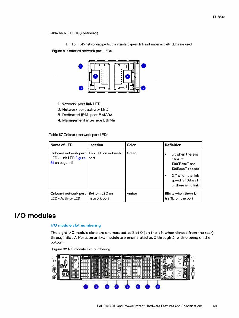
Table 66 I/O LEDs (continued)
a. For RJ45 networking ports, the standard green link and amber activity LEDs are used.
Figure 81 Onboard network port LEDs
1. Network port link LED2. Network port activity LED3. Dedicated IPMI port BMC0A4. Management interface EthMa
Table 67 Onboard network port LEDs
Name of LED Location Color Definition
Onboard network portLED - Link LED Figure81 on page 141
Top LED on networkport
Green l Lit when there isa link at1000BaseT and100BaseT speeds
l Off when the linkspeed is 10BaseTor there is no link
Onboard network portLED - Activity LED
Bottom LED onnetwork port
Amber Blinks when there istraffic on the port
I/O modulesI/O module slot numbering
The eight I/O module slots are enumerated as Slot 0 (on the left when viewed from the rear)through Slot 7. Ports on an I/O module are enumerated as 0 through 3, with 0 being on thebottom.
Figure 82 I/O module slot numbering
DD6800
Dell EMC DD and PowerProtect Hardware Features and Specifications 141

1. Slot 02. Slot 13. Slot 24. Slot 35. Slot 46. Slot 57. Slot 68. Slot 7
I/O modules are only supported in fixed configurations. The fixed configurations define the exactslots into which the I/O modules may be inserted. The processors directly drive the eight I/Omodule slots, meaning all slots are full performance.
The non-optional SAS, NVRAM, and 10GBaseT I/O modules are allocated to fixed slots. Theoptional Host Interface I/O modules are used for front end networking and Fibre Channelconnections. The quantity and type of these I/O modules is customizable, and there are many validconfigurations.
slot map
I/O module slots 3–6 contain optional Host Interface I/O modules and can contain specific I/Omodules or no I/O modules at all. Slot 0, Slot 1, Slot 2, and Slot 7 are populated with the requiredI/O modules and are not optional.
Table 68 I/O module slot mapping
Tier Slot 0 Slot 1 Slot 2 Slot 3 Slot 4 Slot 5 Slot 6 Slot 7
DLH , , or , , or , , or , , or
DLHExtendedRetention/DDCloud Tier
DLH HighAvailability
for HAinterconnect
, , or , , or , , or , , or
I/O module population rulesThe system chassis has eight slots for I/O modules. Slots 0, 1, 2, and 7 are reserved. Slots 3, 4, 5,and 6 support host interface I/O modules. The maximum supported number of any type of hostinterface I/O module is four.
Note: A maximum of three I/O modules are supported in slots 3-6 because of the mandatory I/O module in slot 1.
The following table assigns rules for populating the I/O modules.
Table 69 I/O module slot population rules
Step I/O module name Slots Notes
Step 1: Populatemandatory I/Omodules
0 Mandatory for allconfigurations
1 Mandatory for allconfigurations
DD6800
142 Dell EMC DD and PowerProtect Hardware Features and Specifications

Table 69 I/O module slot population rules (continued)
Step I/O module name Slots Notes
2 Mandatory for allconfigurations
7 Mandatory for allconfigurations
Step 2: Populate all I/O modules
3, 4, 5, 6 Populate startingfrom the lowestavailable slot number.
Step 3: Populate all I/O modules
3, 4, 5, 6 Populate startingfrom the lowestavailable slot number.With in slot 1, maxnumber of I/Omodules are limited to4.
Step 4: Populate all I/O modules
6, 5, 4, 3 Populate startingfrom the highestavailable slot number.
DD6800
Dell EMC DD and PowerProtect Hardware Features and Specifications 143

Internal system componentsThe following figure shows the layout of the CPUs and DIMMs inside the chassis. The front of thesystem is at the top of the figure.
Figure 83 CPU and memory locations
DIMMs overviewDual in-line memory modules (DIMM) come in various sizes, which must be configured in a certainway. This topic can help you select the correct configuration when servicing DIMMs.
The storage processor contains two Intel processors each with an integrated memory controllerthat supports four channels of memory. The storage processor allows two DIMM slots per channel,so the storage processor supports a total of 16 DIMM slots.
memory DIMM configuration
Table 70 memory DIMM configuration
Tier Total Memory Memory DIMM Configuration
DLH 192 GB 8 x 16 GB +8 x 8 GB
DLH Extended Retention/DDCloud Tier
192 GB 8 x 16 GB +8 x 8 GB
HA is supported with all available memory configurations.
To ensure maximum memory performance, there are memory DIMM population rules for bestmemory loading and interleaving. Table 71 on page 144 and Table 72 on page 145 specify theDIMM location rules for various memory configurations:
Table 71 Memory locations - CPU 0
Channel A Channel B Channel D Channel C
Tier TotalMemory
0 1 2 3 4 5 6 7
DLH (Base) 192 GB 16 GB 8 GB 16 GB 8 GB 8 GB 16 GB 8 GB 16 GB
DLH(Expanded)
192 GB 16 GB 8 GB 16 GB 8 GB 8 GB 16 GB 8 GB 16 GB
DD6800
144 Dell EMC DD and PowerProtect Hardware Features and Specifications
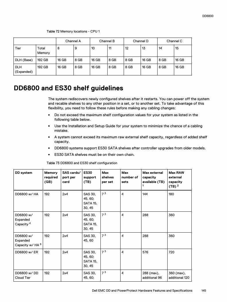
Table 72 Memory locations - CPU 1
Channel A Channel B Channel D Channel C
Tier TotalMemory
8 9 10 11 12 13 14 15
DLH (Base) 192 GB 16 GB 8 GB 16 GB 8 GB 8 GB 16 GB 8 GB 16 GB
DLH(Expanded)
192 GB 16 GB 8 GB 16 GB 8 GB 8 GB 16 GB 8 GB 16 GB
DD6800 and ES30 shelf guidelines
The system rediscovers newly configured shelves after it restarts. You can power off the systemand recable shelves to any other position in a set, or to another set. To take advantage of thisflexibility, you need to follow these rules before making any cabling changes:
l Do not exceed the maximum shelf configuration values for your system as listed in thefollowing table below.
l Use the Installation and Setup Guide for your system to minimize the chance of a cablingmistake.
l A system cannot exceed its maximum raw external shelf capacity, regardless of added shelfcapacity.
l DD6800 systems support ES30 SATA shelves after controller upgrades from older models.
l ES30 SATA shelves must be on their own chain.
Table 73 DD6800 and ES30 shelf configuration
DD system Memoryrequired(GB)
SAS cards/port percard
ES30support(TB)
Maxshelvesper set
Maxnumber ofsets
Max externalcapacityavailable (TB)1
Max RAWexternalcapacity(TB) 2
DD6800 w/ HA 192 2x4 SAS 30,45, 60;SATA 15,30, 45
7 3 4 144 180
DD6800 w/ExpandedCapacity 4
192 2x4 SAS 30,45, 60;SATA 15,30, 45
7 3 4 288 360
DD6800 w/ExpandedCapacity w/ HA 6
192 2x4 SAS 30,45, 60
7 3 4 288 360
DD6800 w/ ER 192 2x4 SAS 30,45, 60;SATA 15,30, 45
7 3 4 576 720
DD6800 w/ DDCloud Tier
192 2x4 SAS 30,45, 60;
7 3 4 288 (max),additional 96
360 (max),additional 120
DD6800
Dell EMC DD and PowerProtect Hardware Features and Specifications 145

Table 73 DD6800 and ES30 shelf configuration (continued)
DD system Memoryrequired(GB)
SAS cards/port percard
ES30support(TB)
Maxshelvesper set
Maxnumber ofsets
Max externalcapacityavailable (TB)1
Max RAWexternalcapacity(TB) 2
SATA 15,30, 45
SAS dedicatedto DD CloudTier
SASdedicated toDD Cloud Tier
DD6800 w/ HAand DD CloudTier 4
192 2x4 SAS 30,45, 60
7 3 4 288 (max),additional 96SAS dedicatedto DD CloudTier
360 (max),additional 120SASdedicated toDD Cloud Tier
1. This figure only counts drives that have user data in the shelves.
2. The raw capacity of an ES30 is 125% of the available capacity.
3. Recommended configurations start at four shelves per set and expand beyond that as required. For HA configurations, the FS15
counts as a shelf.
4. DDOS 6.x and later and FS15 SSD shelf configuration
Types of cabinets and power connectionsThe ES30 chassis is installed in two types of racks: 40U-C (existing racks) and the 40U-P (newerracks). The racks use one phase or 3-phase power connections.
3-Phase power connections for 40U-P (current racks)
Some environments use 3-phase power for 40U-P racks that are used for several systems. Inthose situations, it is desirable to balance the current draw across all three phases. Therecommended 3-phase power cabling attempts to do that, but an optimal configuration dependson the specific installation.
Cabling shelves
Note:
l Before cabling the shelves, physically install all shelves in the racks. Refer to the rail kitinstallation instructions included with the ES30 shelf for rack mounting.
l The documentation refers to two SAS HBAs. If only one HBA is allowed in a system, thenuse another port as defined later for that specific system.
l On an HA system, add cables from the second node to open ports at the end of the sets.The ports on the second node must connect to the same sets as the corresponding portson the first node.
Ports on the system’s SAS HBA cards connect directly to a shelf controller’s host port. Forredundancy, you need to create dual paths by using a port on one SAS HBA card to connect to oneshelf controller in each shelf set, and a port on another SAS HBA card to connect to another shelfcontroller in the same shelf set. With dual paths, if one SAS HBA card fails, the shelf is stilloperational. However, in the unlikely event any single shelf becomes completely disconnected frompower or SAS cables and becomes disconnected from a previously operational shelf, the filesystem goes down and the shelf is not operational. This is considered a double failure.
There are two kinds of configurations: one shelf in a set or multiple shelves in a set.
DD6800
146 Dell EMC DD and PowerProtect Hardware Features and Specifications

DD6300, DD6800, and DD9300 shelf configurationsThere are a few rules that must be followed when adding a mixture of DS60 and other shelf typesto your system.
CAUTION If a system does not follow ALL of these rules it is not a legitimate configuration.
Prerequisites:
l You cannot exceed the maximum amount of raw capacity displayed in the cabling table foreach system.
l You cannot exceed the maximum number of shelves displayed in the cabling table for eachsystem.
l There are no specific placement or cabling requirements for SSD shelves, or the metadatashelves for Cloud Tier configurations. These shelves can be installed and cabled the same wayas standard ES30 shelves.
Table 74 Minimum and maximum configurations
System Appliance Minimum applianceshelf count*
Max appliance shelf count
48 TB usable 0 1
w/ Expansion 144 TB usable 1 5
144 TB usable 2 28
w/ Expansion 288 TB usable 2 28
w/ High Availability(HA)
288 TB usable 2 28
w/ ExtendedRetention (ER)
576 TB usable 2 28
w/ Cloud Tier 288 TB usable(96 TB forCloud Tier)
2 28
w/ HA and Cloud Tier 288 TB usable(96 TB forCloud Tier)
2 28
384 TB usable 3 28
w/ Expansion 720 TB usable 3 28
w/ HA 720 TB usable 3 28
w/ ER 1440 TB usable 7 28
w/ Cloud Tier 720 TB usable(192 TB forCloud Tier)
7 28
w/ HA and Cloud Tier 720 TB usable(192 TB forCloud Tier)
7 28
* The minimum appliance shelf count does not include shelves for Cloud Tier.
DD6800
Dell EMC DD and PowerProtect Hardware Features and Specifications 147

DD6800 and DS60 shelf guidelines
The system rediscovers newly configured shelves after it restarts. You can power off the systemand recable shelves to any other position in a set, or to another set. To take advantage of thisflexibility, you need to follow these rules before making any cabling changes:
l Do not exceed the maximum shelf configuration values for your system as listed in thefollowing table.
l For redundancy, the two connections from a system to a set of shelves must use ports ondifferent SAS I/O modules.
l Use the Installation and Setup Guide for your system to minimize the chance of a cablingmistake.
l A system cannot exceed its maximum raw external shelf capacity, regardless of added shelfcapacity.
l ES30 SATA shelves must be on their own chain.
l If ES30 SAS shelves are on the same chain as a DS60, the maximum number of shelves on thatchain is 5.
Table 75 DD6800 and DS60 shelf configuration
DD system Memoryrequired(GB)
SAScards/port percard
DS60 support(TB)
Maxshelvesper set
Maxnumber ofsets
Maxexternalcapacityavailable(TB)1
Max RAWexternalcapacity(TB)
DD6800 2, 3, 4 192 2x4 SAS 45, 60 1 1 144 180
DD6800 w/ExpandedCapacity 2, 3
192 2x4 SAS 45, 60 1 2 288 360
DD6800 w/ExpandedCapacity and w/HA 2, 3
192 2x4 SAS 45, 60 1 2 288 360
DD6800 w/ExpandedCapacity and w/ER 2, 3
192 2x4 SAS 45, 60 2 4 576 720
DD6800 w/ExpandedCapacity and w/Cloud Tier 3, 5
192 2x4 SAS 45, 60 2 4 288 + 96 forDD CloudTier
360 + 120 forDD Cloud Tier
DD6800 w/ExpandedCapacity and w/Cloud Tier and HA3, 5
192 2x4 SAS 45, 60 2 4 288 + 96 forDD CloudTier
360 + 120 forDD Cloud Tier
Note: An entry of 45 corresponds to DS60-3 models and an entry of 60 corresponds toDS60-4 models.
DD6800
148 Dell EMC DD and PowerProtect Hardware Features and Specifications
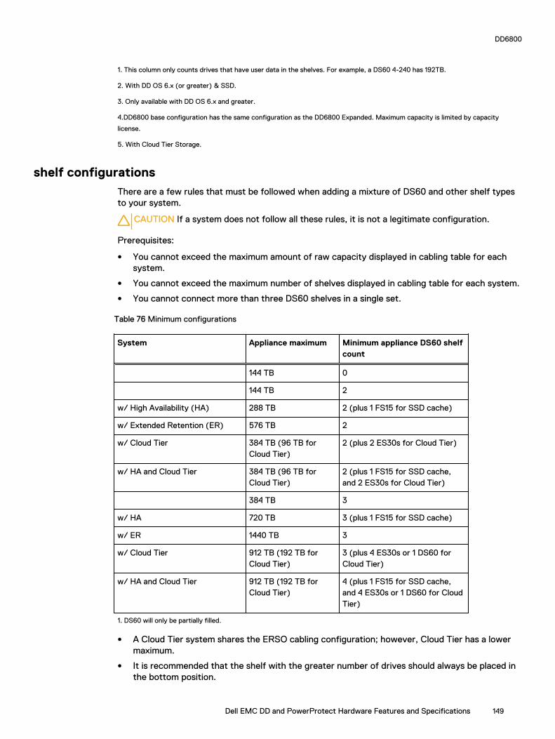
1. This column only counts drives that have user data in the shelves. For example, a DS60 4-240 has 192TB.
2. With DD OS 6.x (or greater) & SSD.
3. Only available with DD OS 6.x and greater.
4.DD6800 base configuration has the same configuration as the DD6800 Expanded. Maximum capacity is limited by capacity
license.
5. With Cloud Tier Storage.
shelf configurationsThere are a few rules that must be followed when adding a mixture of DS60 and other shelf typesto your system.
CAUTION If a system does not follow all these rules, it is not a legitimate configuration.
Prerequisites:
l You cannot exceed the maximum amount of raw capacity displayed in cabling table for eachsystem.
l You cannot exceed the maximum number of shelves displayed in cabling table for each system.
l You cannot connect more than three DS60 shelves in a single set.
Table 76 Minimum configurations
System Appliance maximum Minimum appliance DS60 shelfcount
144 TB 0
144 TB 2
w/ High Availability (HA) 288 TB 2 (plus 1 FS15 for SSD cache)
w/ Extended Retention (ER) 576 TB 2
w/ Cloud Tier 384 TB (96 TB forCloud Tier)
2 (plus 2 ES30s for Cloud Tier)
w/ HA and Cloud Tier 384 TB (96 TB forCloud Tier)
2 (plus 1 FS15 for SSD cache,and 2 ES30s for Cloud Tier)
384 TB 3
w/ HA 720 TB 3 (plus 1 FS15 for SSD cache)
w/ ER 1440 TB 3
w/ Cloud Tier 912 TB (192 TB forCloud Tier)
3 (plus 4 ES30s or 1 DS60 forCloud Tier)
w/ HA and Cloud Tier 912 TB (192 TB forCloud Tier)
4 (plus 1 FS15 for SSD cache,and 4 ES30s or 1 DS60 for CloudTier)
1. DS60 will only be partially filled.
l A Cloud Tier system shares the ERSO cabling configuration; however, Cloud Tier has a lowermaximum.
l It is recommended that the shelf with the greater number of drives should always be placed inthe bottom position.
DD6800
Dell EMC DD and PowerProtect Hardware Features and Specifications 149
l only supports one DS60.
l only has one SAS SLIC and all DS60 connections are made to that single SAS SLIC.
l only has one SAS SLIC and all DS60 connections are made to that single SAS SLIC.
DD6800
150 Dell EMC DD and PowerProtect Hardware Features and Specifications

CHAPTER 6
DD6900
This chapter contains the following topics:
l DD6900 system features..................................................................................................... 152l DD6900 system specifications.............................................................................................153l DD6900 storage capacity and configurations...................................................................... 154l DD6900 front panel............................................................................................................. 155l DD6900 SSD usage and configurations............................................................................... 158l Rear panel............................................................................................................................159l PCIe HBAs............................................................................................................................161l DD6900 DIMM configurations............................................................................................. 163l DD6900, DD9400, and DD9900 storage shelves configurations and capacities................... 163
Dell EMC DD and PowerProtect Hardware Features and Specifications 151

DD6900 system features
Table 77 DD6900 system features
Configurations Single Node HA A-P
Processor 2 x Intel Xeon Silver, 2095 Mhz, 8C
Kernel 4.4
MemoryConfigurations
Total 288 GB
DIMMs 12 x 8 GB + 12 x 16 GB
HDD Drive Size 4TB
SupportedCapacity
Active Tier 48 <-> 288 TBu
Cloud Tier 576 TBu
Disk Groups Active Tier 1 <-> 6
Cloud Tier (4 TB) 2
SSDs for OS in 2.5" bays in head 4, 0.96 TB, 1 WPD
Stream Count 400 Wr, 110 Rd
Cache SSDs 1.2% 2 (Internal) 1.92 TB 2 (External) 3.84 TB
Cache SSD shelf FS25 0 1
HA Private Interconnect N/A (2) 10G Base-Tports (NDC)
16 GB NVRAM 1
HW Accelerator 100 Quick AssistTechnology (QAT) 8970
1
Internal SAS HBA330 12 Gbps SAScontroller
1
External SAS PMC Quad Port 12 GbpsSAS
2 minimum, 3 maximum
SAS String Depth(max)
ES30/ES40 6 (7 for Cloud Tier)
DS60 2
Host interfaceHBAs
2-port QL41000 25 GbE-SFP28
4 maximum
4-port QL41164 10 GbE-SFP+
3 maximum
4-port QL41164 10GBASE-T
4 maximum
4-port QLE2694 16 Gb FC 3 maximum
Network DaughterCard option
4-port QL41000 10 GbE-SP+ FasLinQ
1
DD6900
152 Dell EMC DD and PowerProtect Hardware Features and Specifications

Table 77 DD6900 system features (continued)
Configurations Single Node HA A-P
4-port QL41164 10GBASE-T
1
DD6900 system specifications
Figure 84 System dimensions
Table 78 DD6900 system specifications
Xa Xb Y Za (withbezel)
Za(withoutbezel)
Zb Zc
482.0 mm(18.98inches)
434.0 mm(17.09inches)
86.8 mm(3.42inches)
35.84 mm(1.41inches)
22.0 mm(0.87inches)
678.8 mm(26.72inches)
715.5 mm(28.17inches)
A DD6900 system weighs up to 63.05 lbs (28.6 kg).
Table 79 System operating environment
Operating Temperature 50° to 95° F (10° to 35° C), derate 1.1° Cper 1000 feet, above 7500 feet up to 10,000feet (32.25° C at 10,000
Operating Humidity 20% to 80%, non-condensing
Non-operating Temperature -40° to +149° F (-40° to +65° C)
DD6900
Dell EMC DD and PowerProtect Hardware Features and Specifications 153

Table 79 System operating environment (continued)
Operating Acoustic Noise L wad sound power, 7.5 Bels
DD6900 storage capacity and configurationsThe following table provides storage capacity and configuration information for the DD6900system:
Table 80 DD6900 storage capacity and configurations
Tier CPU-SP SKU Memory Front 2.5" SSDs Max. UseableCapacity
DD6900 8 core, 85 W4208
288 GB (12 x 16GB) + (12 x 8GB)
1 (1.2%) 288 TB
DD6900 with DDCloud Tier1
8 core, 85 W4208
288 GB (12 x 16GB) + (12 x 8GB)
1 (1.2%) 576 TB
1 DD Cloud Tier can be added to a DD6900 and is enabled by a license and disk packs for the DDCloud Tier metadata.
The Memory column lists the total memory that is required and the number and type of the DIMMsused. All memory DIMMs are DDR4 RDIMMs at the highest supported speed of 2400MT/s.
High Availability
DD6900 supports Active-Passive High Availability (A-P HA or just A-P). The following tablesummarizes the hardware changes to support A-P HA:
Table 81 HA configuration requirements
Hardware Changeto support HA
Active-Passive HA
Additional memory No extra memory required.
HA privateinterconnect
Cluster Interconnect : A-P requires the use of two ports from the on-board quad-port 10 GbE Network Daughter Card.
NVRAM A-P requires a single 16 GB NVRAM card (same as non-HA).
SAS Connectivity Both nodes of an A-P HA pair require redundant SAS connectivity tothe storage array. (Note: a single node system also has redundantconnectivity to the storage array.)
SSD Requirements SSDs are contained within FS25 and are available from both nodes.
HA Network Interconnect
The HA Network Interconnect, required for HA configurations, is a dedicated 10 GbE connectionbetween the two nodes of an HA pair. The interconnect is used to write data (and metadata) fromthe active node's NVRAM to the passive node's NVRAM.
DD6900
154 Dell EMC DD and PowerProtect Hardware Features and Specifications

Two 10GbE links are used to meet the bandwidth requirements for the private interconnect.Traffic across the private interconnect has roughly the same bandwidth as is written to theNVRAM card. The dual 10-GbE links can move about 2 GB/s in each direction.
HA SAS Interconnect
HA configurations require that the SSDs' cache drives be shared between both nodes and haveredundant SAS connections to all shelves.
DD6900 front panel
Figure 85 DD6900 front panel
Table 82 Front panel features
Item
Ports, panels, andslots
Description
1 Left control panel Contains system health and system ID, status LED, andoptional iDRAC Quick Sync 2 (wireless).
2 Drive slots Enable you to install drives that are supported on yoursystem.
3 Right control panel Contains the power button, VGA port, iDRAC Direct microUSB port, and two USB 2.0 ports.
4 Information tag The Information tag is a slide-out label panel that containssystem information such as Service Tag, NIC, MAC address,and so on. If you have opted for the secure default access toiDRAC, the Information tag also contains the iDRAC securedefault password.
Table 83 Front LEDs
Name Color Purpose
Control Panel Status LED Blue/Amber Status:
l Healthy: Solid Blue
l Fault: Blink Amber
l Sys ID: Blink Blue
DD6900
Dell EMC DD and PowerProtect Hardware Features and Specifications 155

Table 83 Front LEDs (continued)
Name Color Purpose
System Power Button/LED Green Indication that the system has power.
Drive activity LEDs Green Lit green when the drive is powered. Blinksduring drive activity.
Drive service LEDs Green Lit solid amber when a disk drive needsservice.
Front LEDs
Figure 86 Front left control panel status LEDs
Note: The indicators display solid amber if any error occurs.
Table 84 System health and system ID indicator codes
System health and IDindicator code
Solid blue Indicates that the system is turned on, system is healthy, andsystem ID mode is not active. Press the system health andsystem ID button to switch to system ID mode.
Blinking blue Indicates that the system ID mode is active. Press thesystem health and system ID button to switch to systemhealth mode.
Solid amber Indicates that the system is in fail-safe mode.
Blinking amber Indicates that the system is experiencing a fault. Check theSystem event log or the LCD panel, if available on the bezel,for specific error messages.
DD6900
156 Dell EMC DD and PowerProtect Hardware Features and Specifications

Figure 87 Front right control panel power button LEDs
Table 85 Right control panel features
Item Indicator, button, orconnector
Description
1 Power button Indicates if the system is turned on or off. Press the powerbutton to manually turn on or off the system.
Note: Press the power button to gracefully shut downan ACPI-compliant operating system.
2 USB port (2) The USB ports are 4-pin, 2.0-compliant. These ports enableyou to connect USB devices to the system.
3 iDRAC Direct port The iDRAC Direct port is micro USB 2.0-compliant. This portenables you to access the iDRAC Direct features.
4 iDRAC Direct LED The iDRAC Direct LED indicator lights up to indicate that theiDRAC Direct port is connected.
5 VGA port Enables you to connect a display device to the system.
Table 86 iDRAC Direct LED indicator codes
iDRAC Direct LEDindicator code
Condition
Solid green for twoseconds
Indicates that the laptop or tablet is connected.
Flashing green (on for twoseconds and off for twoseconds)
Indicates that the laptop or tablet that is connected isrecognized.
Turns of Indicates that the laptop or tablet is unplugged.
DD6900
Dell EMC DD and PowerProtect Hardware Features and Specifications 157
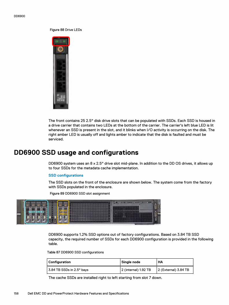
Figure 88 Drive LEDs
The front contains 25 2.5" disk drive slots that can be populated with SSDs. Each SSD is housed ina drive carrier that contains two LEDs at the bottom of the carrier. The carrier's left blue LED is litwhenever an SSD is present in the slot, and it blinks when I/O activity is occurring on the disk. Theright amber LED is usually off and lights amber to indicate that the disk is faulted and must beserviced.
DD6900 SSD usage and configurations
DD6900 system uses an 8 x 2.5" drive slot mid-plane. In addition to the DD OS drives, it allows upto four SSDs for the metadata cache implementation.
SSD configurations
The SSD slots on the front of the enclosure are shown below. The system come from the factorywith SSDs populated in the enclosure.
Figure 89 DD6900 SSD slot assignment
DD6900 supports 1.2% SSD options out of factory configurations. Based on 3.84 TB SSDcapacity, the required number of SSDs for each DD6900 configuration is provided in the followingtable.
Table 87 DD6900 SSD configurations
Configuration Single node HA
3.84 TB SSDs in 2.5" bays 2 (internal) 1.92 TB 2 (External) 3.84 TB
The cache SSDs are installed right to left starting from slot 7 down.
DD6900
158 Dell EMC DD and PowerProtect Hardware Features and Specifications

SSD boot drives
Additional SAS SSDs are used to boot the DD OS operating system. Boot disks and/or externaldisk shelves are used to log system information. Boot disks are installed from the other end of thefront 2.5" disk slots to physically differentiate the cache SSDs.
Table 88 SSD boot drives
# of boot disks Installed in slots
4 0,1,2,3
Rear panel
Figure 90 System rear panel
Item Panels, ports, and slots Description
1 Full-height PCIe expansioncard slot (3)
The PCIe expansion card slot (riser 1) connects up to three full-height PCIeexpansion cards to the system.
2 Half-height PCIeexpansion card slot
The PCIe expansion card slot (riser 2) connects one half-height PCIe expansioncards to the system.
3 Rear handle The rear handle can be removed to enable any external cabling of PCIe cardsthat are installed in the PCIe expansion card slot 6.
4 Full-height PCIe expansioncard slot (2)
The PCIe expansion card slot (riser 2) connects up to two full-height PCIeexpansion cards to the system.
5 Full-height PCIe expansioncard slot (2)
The PCIe expansion card slot (riser 3) connects up to two full-height PCIeexpansion cards to the system.
6 Power supply unit (2) Supports up to two AC or DC power supply units (PSUs)
7 NIC ports The NIC ports that are integrated on the network daughter card (NDC) providenetwork connectivity.
8 USB port (2) The USB ports are 9-pin and 3.0-compliant. These ports enable you to connectUSB devices to the system.
DD6900
Dell EMC DD and PowerProtect Hardware Features and Specifications 159

Item Panels, ports, and slots Description
9 VGA port Enables you to connect a display device to the system.
10 Serial port Enables you to connect a serial device to the system.
11 iDRAC9 dedicated port Enables you to remotely access iDRAC.
12 System identificationbutton
The System Identification (ID) button is available on the front and back of thesystems. Press the button to identify a system in a rack by turning on thesystem ID button. You can also use the system ID button to reset iDRAC and toaccess BIOS using the step through mode.
Rear LEDs
Figure 91 Onboard ID and iDRAC LEDs
1. iDRAC management port:
a. The green link LED on the left is lit whenever there is link at 1000BaseT and 100BaseTspeeds. The link LED is off when the link speed is 10BaseT or there is no link.
b. The green link LED on the right blinks whenever there is traffic on the port.
2. System identification LED: This blue LED can be turned on by software to visually identify thesystem.
PSU FRU LEDs
There are two power supplies, one in the upper left of the rear chassis and one on the bottomright. Each power supply has three LEDs: AC good, DC good, and Service. The top PSU is "right-side up" and the bottom PSU is "upside down."
Table 89 PSU FRU LEDs
Name Color Definition
AC Good Green AC input is as expected.
DC Good Green DC output is as expected.
Service Amber PSU has a fault condition anda must be replaced.
DD6900
160 Dell EMC DD and PowerProtect Hardware Features and Specifications

PCIe HBAs
A slot in the chassis that does not contain an HBA must have a filler panel installed in the emptyslots. This is required for EMI compliance.
This system supports eight I/O modules slots, 4 of which are 8-lane PCIe Gen3, and two are 16-lane PCIe Gen3. Several networking, NVRAM, SAS, and Fibre Channel I/O modules are supported.
Slot assignment
The following table lists the DD6900 configuration slot assignments:
Table 90 DD6900 slot assignments
Description Slot
QLogic, 41164 4 Port, 10GbE SFP+ PCIe, FullHeight
5, 8, 1
QLogic, 41164 4 Port, 10GBASE-T PCIe, FullHeight
5, 8, 1
QLogic, 41164 4 Port, 10GBASE-T PCIe, LowProfile
6
QLogic, 41262 2 Port, 25Gb SFP28 PCIe, FullHeight
5, 8, 1
QLogic, 41262 2 Port, 25Gb SFP28 PCIe, LowProfile
6
HBA330 SAS Controller, 12Gbps Mini card mini/mono
QAT,INTEL,8970,FH, Avnet p/n1QA89701G1P5
4
PM8072,SAS12,4P,FH, MicroSemi 2295200-R
3, 7, 5
FC16,QLE2694-DEL-BK,TRG,QP,FH 5, 8, 1
16GB NVRAM,FH 3
Host Interface (x16) is 2-port 100 Gb QSFP+ Ethernet.
Host Interface (x8) are:
l 4-port 25 Gb SFP28 Ethernetl 4-port 10 Gb SFP+ Ethernetl 4-port 10GBaseT Ethernetl 4-port 16 Gb Fibre Channel
Note: Any of the Host Interface (x8) may be inserted into the slots 1, 2, & 5, but the HostInterface (x16) may only reside in slot 2 (the x16 slots).
SAS is 4-port 12 Gb SAS and is required for HA configurations.
NVRAM is the 16GB NVRAM.
SAS Mezzanine is 2-port 12 Gb Mini-SAS HD SAS controller mezzanine.
Host Interface Mezzanine is either:
DD6900
Dell EMC DD and PowerProtect Hardware Features and Specifications 161

l 4-port 10GBaseSR SFP+ Ethernet mezzanine
l 4-port 10GBaseT RJ45 Ethernet mezzanine
I/O population rules
The following figures show the I/O module slot numbers.
The slot labeled N is the network daughter card, which contains ports ethMa, ethMb, ethMc, andethMd.
The physical interface name format for the other I/O module slots is ethXy, where X is the slotnumber and y is an alphanumeric character. For example, eth0a.
For most horizontal I/O module NIC interfaces, the port numbering goes from left to right, withethXa on the left. The horizontal I/O module slots on the left-in slots 1-3 are inverted. The portnumbering on these I/O modules in these slots goes from right to left, with ethXa on the right.
The management port ethMa is the first port set up by the Configuration Wizard. It is marked witha red rectangle in the figure below.
Figure 92 Slot numbering
The general population rules can be summarized as:
1. Populate a given I/O in the available slots listed.
2. Select the first available slot in the group.
3. Follow the steps for each I/O in the order specified.
4. Slots 0 and 2 should be reserved for x16 unless there are no available x8 slots.
Note: Installing HBAs requires opening the system and installing the HBA into the riser.
Riser# Slots (from top to bottom)
1 1, 2, 3
2 4, 5, 6, N
3 7, 8
Gen3 PCIe
Slots support Gen3 PCIe.
I/O module servicing
All I/O modules are user serviceable and may be replaced when the system is powered off. On-lineservice of I/O modules is not support. A module that is hot-inserted into the system will remainpowered off and will not be powered on until the next reboot of the system. A module that is hot-removed causes an operating system to immediately reboot.
DD6900
162 Dell EMC DD and PowerProtect Hardware Features and Specifications
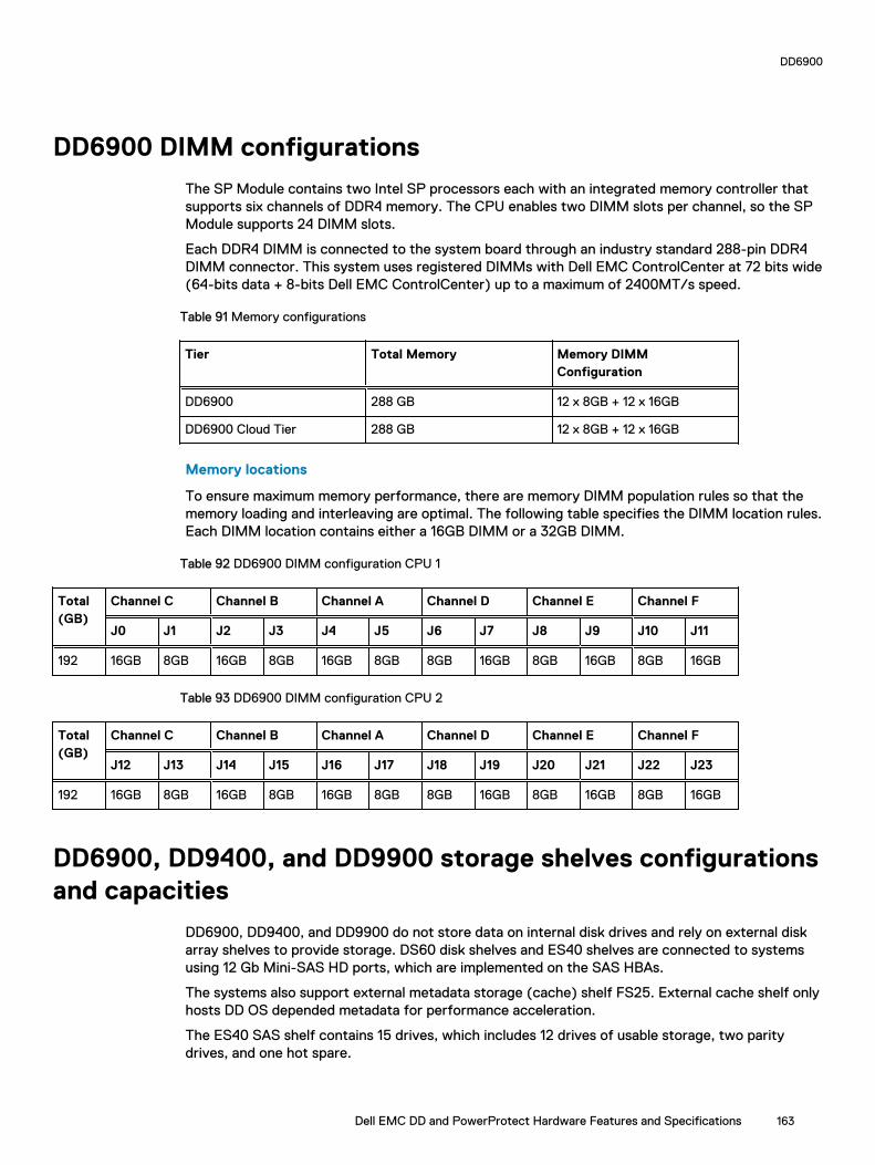
DD6900 DIMM configurations
The SP Module contains two Intel SP processors each with an integrated memory controller thatsupports six channels of DDR4 memory. The CPU enables two DIMM slots per channel, so the SPModule supports 24 DIMM slots.
Each DDR4 DIMM is connected to the system board through an industry standard 288-pin DDR4DIMM connector. This system uses registered DIMMs with Dell EMC ControlCenter at 72 bits wide(64-bits data + 8-bits Dell EMC ControlCenter) up to a maximum of 2400MT/s speed.
Table 91 Memory configurations
Tier Total Memory Memory DIMMConfiguration
DD6900 288 GB 12 x 8GB + 12 x 16GB
DD6900 Cloud Tier 288 GB 12 x 8GB + 12 x 16GB
Memory locations
To ensure maximum memory performance, there are memory DIMM population rules so that thememory loading and interleaving are optimal. The following table specifies the DIMM location rules.Each DIMM location contains either a 16GB DIMM or a 32GB DIMM.
Table 92 DD6900 DIMM configuration CPU 1
Total(GB)
Channel C Channel B Channel A Channel D Channel E Channel F
J0 J1 J2 J3 J4 J5 J6 J7 J8 J9 J10 J11
192 16GB 8GB 16GB 8GB 16GB 8GB 8GB 16GB 8GB 16GB 8GB 16GB
Table 93 DD6900 DIMM configuration CPU 2
Total(GB)
Channel C Channel B Channel A Channel D Channel E Channel F
J12 J13 J14 J15 J16 J17 J18 J19 J20 J21 J22 J23
192 16GB 8GB 16GB 8GB 16GB 8GB 8GB 16GB 8GB 16GB 8GB 16GB
DD6900, DD9400, and DD9900 storage shelves configurationsand capacities
DD6900, DD9400, and DD9900 do not store data on internal disk drives and rely on external diskarray shelves to provide storage. DS60 disk shelves and ES40 shelves are connected to systemsusing 12 Gb Mini-SAS HD ports, which are implemented on the SAS HBAs.
The systems also support external metadata storage (cache) shelf FS25. External cache shelf onlyhosts DD OS depended metadata for performance acceleration.
The ES40 SAS shelf contains 15 drives, which includes 12 drives of usable storage, two paritydrives, and one hot spare.
DD6900
Dell EMC DD and PowerProtect Hardware Features and Specifications 163

The DS60 shelf contains 60 drives. Drives are configured in four groups of 15 drives. Each groupcontains two parity drives and one hot spare, so each group provides 12 drives of usable storage. Afully configured DS60 shelf provides 48 drives of usable storage.
Table 94 Shelves shipped from factory, in rack
DD6900 DD9400 DD9900
4 TB ES40 8 TB DS60 8 TB DS60
Table 95 Shelves shipped from factory, boxed
DD6900 DD9400 DD9900
4 TB ES40 8 TB ES40 8 TB ES40
4 TB DS60 8 TB DS60 8 TB DS60
Table 96 Additional shelves supported
DD6900 DD9400 DD9900
4 TB SAS ES30/DS60 4 TB SAS ES30/DS60 4 TB SAS ES30/DS60
3 TB SAS ES30/DS60 3 TB SAS ES30/DS60 3 TB SAS ES30/DS60
Note: 3 TB shelves are only support on controller upgrades and not on fresh installs.
Table 97 Shelf usable capacities
Hard drive size (TB) Shelf Useable TB
4 ES40 48
4 DS60 192
8 DS60 384
The following table lists the maximum number of shelves per chain:
Table 98 Supported shelf count per chain
Shelf type Max # from factory Max # per chain
SAS ES30/ES40 4 7
DS60 2 3
DS60 + ES30/ES40 n/a 5
F25 1 1
The connector type for ES30 is Mini-SAS. Special cables may be necessary when combining ES30and ES40 shelves on the same chain (enabled but not recommended).
DD9400 and DD9900 system capacities are optimized for use with DS60 shelves containing 8 TBdrives. DS60 shelves can be populated with one to four packs of fifteen 8 TB, or 4 TB drives.Different 4 TB and 8 TB capacity disk packs may be mixed within a single DS60 shelf. ES40 SASshelves and DS60 shelves of mixed capacities may be attached so long as the maximum storagecapacity of the system is not exceeded.
DD6900
164 Dell EMC DD and PowerProtect Hardware Features and Specifications

CHAPTER 7
DD7200
This chapter contains the following topics:
l DD7200 system features......................................................................................................166l DD7200 system specifications............................................................................................. 167l DD7200 storage capacity.....................................................................................................168l Front Panel.......................................................................................................................... 169l Back Panel........................................................................................................................... 173l I/O modules and slot assignments........................................................................................175l Internal system components.................................................................................................177l DD7200 and ES30 shelf guidelines....................................................................................... 177l DD7200 and DS60 shelf guidelines...................................................................................... 186
Dell EMC DD and PowerProtect Hardware Features and Specifications 165

DD7200 system featuresThe table summarizes the DD7200 system features.
Table 99 DD7200 system features
Feature DD7200 (Baseconfiguration)
DD7200 (Expandedconfiguration)
Rack height 4U, supported infour-post racks only
4U, supported in four-post racksonly
Rack mounting Rack mount kitincluded with eachsystem. Adjustablebetween 24 - 36 in.(60.9 - 76.2 cm).
Rack mount kit included witheach system. Adjustable between24 - 36 in. (60.9 - 76.2 cm).
Power 1 +1 redundant, hot-swappable powerunits
1 +1 redundant, hot-swappablepower units
Processor Two 8-coreprocessors
Two 8-core processors
NVRAM One 4-GB NVRAMmodule (andcompanion BBU) fordata integrity duringa power outage
One 4-GB NVRAM module (andcompanion BBU) for dataintegrity during a power outage
Fans Hot-swappable,redundant, 5
Hot-swappable, redundant, 5
Memory 8 x 16 GB DIMM (128GB)
16 x 16 GB DIMM (256 GB)
Internal drives SSD drives, 3 x 200GB (base 10)
SSD drives, 3 x 200 GB (base 10)
I/O module slots Nine replaceable I/Omodule (FibreChannel, Ethernet,and SAS) slots, oneBBU, one NVRAM,and one Managementmodule slot. See Management moduleand interfaces onpage 47 and I/Omodules and slotassignments on page49.
Nine replaceable I/O module(Fibre Channel, Ethernet, andSAS) slots, one BBU, oneNVRAM, and one Managementmodule slot. See Managementmodule and interfaces on page 47and I/O modules and slotassignments on page 49.
Supported capacity Non-extended retention 12 x 2-TB or 8 x 3-TBshelves adding up to285 TB of usableexternal capacity.
8 x 2-TB or 12 x 3-TB shelvesadding up to 428 TB of usableexternal capacity.
DD7200
166 Dell EMC DD and PowerProtect Hardware Features and Specifications

Table 99 DD7200 system features (continued)
Feature DD7200 (Baseconfiguration)
DD7200 (Expandedconfiguration)
DD Cloud Tier N/A 428 TB of Active Tier capacity,and 856 TB of Cloud Tiercapacity. 4 x 4 TB shelves arerequired to store DD Cloud Tiermetadata.
DD Extended Retention N/A 56 shelves adding up to amaximum of 856 GB of usableexternal capacity.
DD7200 system specifications
Table 100 DD7200 system specifications
Model Watts BTU/hr Power Weight Width Depth Height
DD7200 800 2730 800 80 lb / 36.3kg
17.5 in (44.5cm)
33 in (84cm)
7 in (17.8cm)
Table 101 System operating environment
Operating Temperature 50° to 95° F (10° to 35° C), derate 1.1° Cper 1000 feet, above 7500 feet up to 10,000feet
Operating Humidity 20% to 80%, non-condensing
Non-operating Temperature -40° to +149° F (-40° to +65° C)
Operating Acoustic Noise Sound power, LWAd: 7.52 bels. Soundpressure, LpAm: 56.4 dB. (Declared noiseemission per ISO 9296.)
DD7200
Dell EMC DD and PowerProtect Hardware Features and Specifications 167

DD7200 storage capacityThe table lists the capacities of the systems. Data Domain system internal indexes and otherproduct components use variable amounts of storage, depending on the type of data and the sizesof files. If you send different datasets to otherwise identical systems, one system may, over time,have room for more or less actual backup data than another.
Table 102 DD7200 storage capacity
System/ InstalledMemory
Internal Disks(SATA SSDs)
Data StorageSpace
External Storage3
DD7200(2 SAS I/Omodules)
128 GB
2.5 in. 3 @ 200 GBNo User Data
285 TB Up to a maximum of 12 x 2-TBor 8 x 3-TB shelves.
DD7200(2 SAS I/Omodules)
256 GB
2.5 in. 3 @ 200 GBNo User Data
428 TB Up to a maximum of 18 x 2-TBor 12 x 3-TB shelves.
DD7200 with DDCloud Tier1
(4 SAS I/Omodules)
256 GB
2.5 in. 3 @ 200 GBNo User Data
l 428 TB (ActiveTier)
l 192 TB (DDCloud Tiermetadata)
l 856 TB (DDCloud Tier)
Up to a maximum of 18 x 2-TBor 12 x 3-TB shelves.4x4-TB shelves for DD CloudTier metadata.
DD7200 withExtendedRetentionsoftware1
(4 SAS I/Omodules)
256 GB
2.5 in. 3 @ 200 GBNo User Data
856 TB Up to a maximum of 36 x 2-TB or 24 x 3-TB shelves.
1Data Domain DD7200 controller with DD Extended Retention software.2 Data Domain DD7200 controller with DD Cloud Tier.3 The capacity differs depending on the size of the external storage shelves used. This data basedon ES30 shelves.
DD7200
168 Dell EMC DD and PowerProtect Hardware Features and Specifications
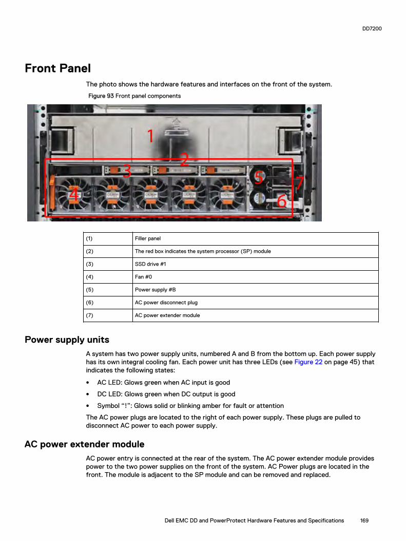
Front PanelThe photo shows the hardware features and interfaces on the front of the system.
Figure 93 Front panel components
(1) Filler panel
(2) The red box indicates the system processor (SP) module
(3) SSD drive #1
(4) Fan #0
(5) Power supply #B
(6) AC power disconnect plug
(7) AC power extender module
Power supply unitsA system has two power supply units, numbered A and B from the bottom up. Each power supplyhas its own integral cooling fan. Each power unit has three LEDs (see Figure 22 on page 45) thatindicates the following states:
l AC LED: Glows green when AC input is good
l DC LED: Glows green when DC output is good
l Symbol “!”: Glows solid or blinking amber for fault or attention
The AC power plugs are located to the right of each power supply. These plugs are pulled todisconnect AC power to each power supply.
AC power extender moduleAC power entry is connected at the rear of the system. The AC power extender module providespower to the two power supplies on the front of the system. AC Power plugs are located in thefront. The module is adjacent to the SP module and can be removed and replaced.
DD7200
Dell EMC DD and PowerProtect Hardware Features and Specifications 169
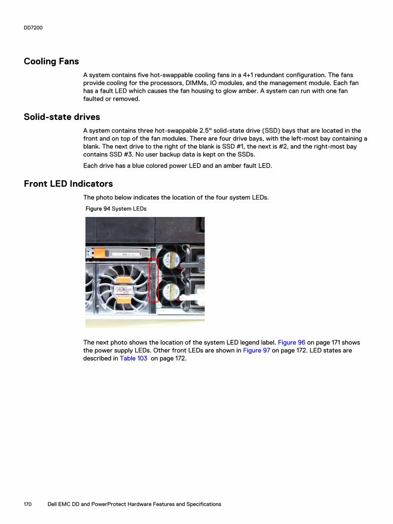
Cooling FansA system contains five hot-swappable cooling fans in a 4+1 redundant configuration. The fansprovide cooling for the processors, DIMMs, IO modules, and the management module. Each fanhas a fault LED which causes the fan housing to glow amber. A system can run with one fanfaulted or removed.
Solid-state drivesA system contains three hot-swappable 2.5" solid-state drive (SSD) bays that are located in thefront and on top of the fan modules. There are four drive bays, with the left-most bay containing ablank. The next drive to the right of the blank is SSD #1, the next is #2, and the right-most baycontains SSD #3. No user backup data is kept on the SSDs.
Each drive has a blue colored power LED and an amber fault LED.
Front LED IndicatorsThe photo below indicates the location of the four system LEDs.
Figure 94 System LEDs
The next photo shows the location of the system LED legend label. Figure 96 on page 171 showsthe power supply LEDs. Other front LEDs are shown in Figure 97 on page 172. LED states aredescribed in Table 103 on page 172.
DD7200
170 Dell EMC DD and PowerProtect Hardware Features and Specifications

Figure 95 System LED legend label
The power supply LEDs include:
l AC LED on top
l DC LED in the middle
l Failure LED on the bottom
Figure 96 Power supply LEDs
Each SSD has two LEDs as shown in the following figure. The lower left corner of the housingaround each fan acts as an LED, glowing amber when the fan has failed.
DD7200
Dell EMC DD and PowerProtect Hardware Features and Specifications 171

Figure 97 Fan and SSD LEDs
Table 103 LED status indicators
Part Description or Location State
System Dot within a circle (top LED) Blue indicates power on andnormal operation.
System, SP fault Exclamation point within atriangle
Dark indicates normaloperation. Amber indicatesfailure.
System, chassis fault Exclamation point within atriangle with a light below
Dark indicates normaloperation. Yellow indicates afault condition.
System Marked out hand within ablack square (bottom LED)
White warms not to removethe unit.
Power supply AC LED Steady green indicates normalAC power.
Power supply DC LED Steady green indicates normalDC power.
Power supply Failure LED Solid amber indicates a failedpower supply.
SSD Top LED Solid blue, disk ready, blinkswhile busy.
SSD Bottom LED Dark indicates healthy. Solidamber indicates disk fail.
Fan Fan housing The fan housing glows anamber color during fan failure.
DD7200
172 Dell EMC DD and PowerProtect Hardware Features and Specifications

Back PanelThe photo shows the hardware features and interfaces on the back of the system.
Figure 98 Features on rear of chassis
1. Upper level contains all blanks2. AC power extender module3. Management module (slot Mgmt A)4. Red box indicating I/O modules (slots 0-8)5. Battery backup (BBU in slot 9)6. NVRAM module (slot 10)7. Cage covering the BBU and NVRAM combination module8. I/O LED at the end of each I/O module handle9. Location of serial number label/tag
Note: For modules containing multiple ports, the bottom port is numbered as zero (0) withnumbers increasing going upward.
I/O module LEDsEach I/O module ejector handle contains a bi-colored LED. Green indicates normal function, whilean amber color indicates a fault condition.
Management module and interfacesThe management module is on the left-most side when facing the back of the system, in slotMgmt A. The process to remove and add a management module is the same as the I/O modules,however, the management module can only be accommodated in Mgmt A slot.
The management module contains one external LAN connection for management access to the SPmodule. One micro DB-9 connector is included to provide the console. A USB port is provided foruse during service of the system to allow booting from a USB flash device.
DD7200
Dell EMC DD and PowerProtect Hardware Features and Specifications 173

Figure 99 Interfaces on the management module
l 1 - Ethernet port
l 2 - USB port
l 3 - Micro serial port
DD7200
174 Dell EMC DD and PowerProtect Hardware Features and Specifications

I/O modules and slot assignmentsThe table shows the I/O module slot assignments for the systems. See Figure 25 on page 47 for aview of the slot positions on the back panel and Figure 27 on page 51 for a top view.
Table 104 DD7200 slot assignments
Slot Number DD7200 DD7200 with ExtendedRetention Software
DD7200 with DD CloudTier
MGMT A Management module Management module Management module
0 Fibre Channel (FC), Ethernet orempty
FC, Ethernet or empty FC, Ethernet or empty
1 FC, Ethernet or empty FC, Ethernet or empty FC, Ethernet or empty
2 FC, Ethernet or empty FC, Ethernet or empty FC, Ethernet or empty
3 FC, Ethernet or empty FC, Ethernet or empty FC, Ethernet or empty
4 Ethernet or empty Ethernet or empty Ethernet or empty
5 Ethernet or empty SAS SAS
6 Empty SAS SAS
7 SAS SAS SAS
8 SAS SAS SAS
9 BBU BBU BBU
10 NVRAM NVRAM NVRAM
Slot addition rulesl A maximum of six optional I/O modules (FC plus Ethernet) are allowed in systems without
Extended Retention software, and a maximum of five optional I/O modules (FC plus Ethernet)are allowed in systems with Extended Retention software.
l Additional FC modules should be installed in numerically increasing slot numbers immediately tothe right of the existing FC modules, or starting in slot 0 if no FC modules were originallyinstalled. A maximum of four FC modules are allowed in a system.
l Additional Ethernet modules should be installed in numerically decreasing slot numbersimmediately to the left of the existing Ethernet modules or starting in slot 4 if no Ethernetmodules were originally installed. For systems without Extended Retention software, amaximum of six (limited to four of any one type) Ethernet modules can be present. Forsystems with Extended Retention software, a maximum of five (limited to four of any onetype) Ethernet modules can be present.
l All systems include two SAS modules in slots 7 and 8. Systems with Extended Retentionsoftware must have two additional SAS modules in slots 5 and 6.
l For systems without Extended Retention software, if adding I/O modules results in the allowedmaximum of six I/O modules present, slot 5 is used. Slot 5 is only used for an Ethernet module.Adding FC modules in this specific case require moving an existing Ethernet module to slot 5.Other than this specific case, it is not recommended to move I/O modules between slots.
DD7200
Dell EMC DD and PowerProtect Hardware Features and Specifications 175

l Adding Extended Retention software to a system includes adding two SAS modules in slots 5and 6. If the system originally had the maximum of 6 optional I/O modules, the I/O module inslot 5 must be permanently removed from the system.
Fibre Channel (FC) I/O Module OptionAn FC I/O module is a dual-port Fibre Channel module. The optional virtual tape library (VTL)feature requires at least one FC I/O module. Boost over Fiber Channel is optional and the total FCHBAs cannot exceed more than allowable Fibre Channel cards per controller.
Ethernet I/O Module OptionsThe available Ethernet I/O modules are:
l Dual Port 10GBase-SR Optical with LC connectors
l Dual Port 10GBase-CX1 Direct Attach Copper with SPF+ module
l Quad Port 1000Base-T Copper with RJ-45 connectors
l Quad port 2 port 1000Base-T Copper (RJ45) /2 port 1000Base-SR Optical
DD7200
176 Dell EMC DD and PowerProtect Hardware Features and Specifications
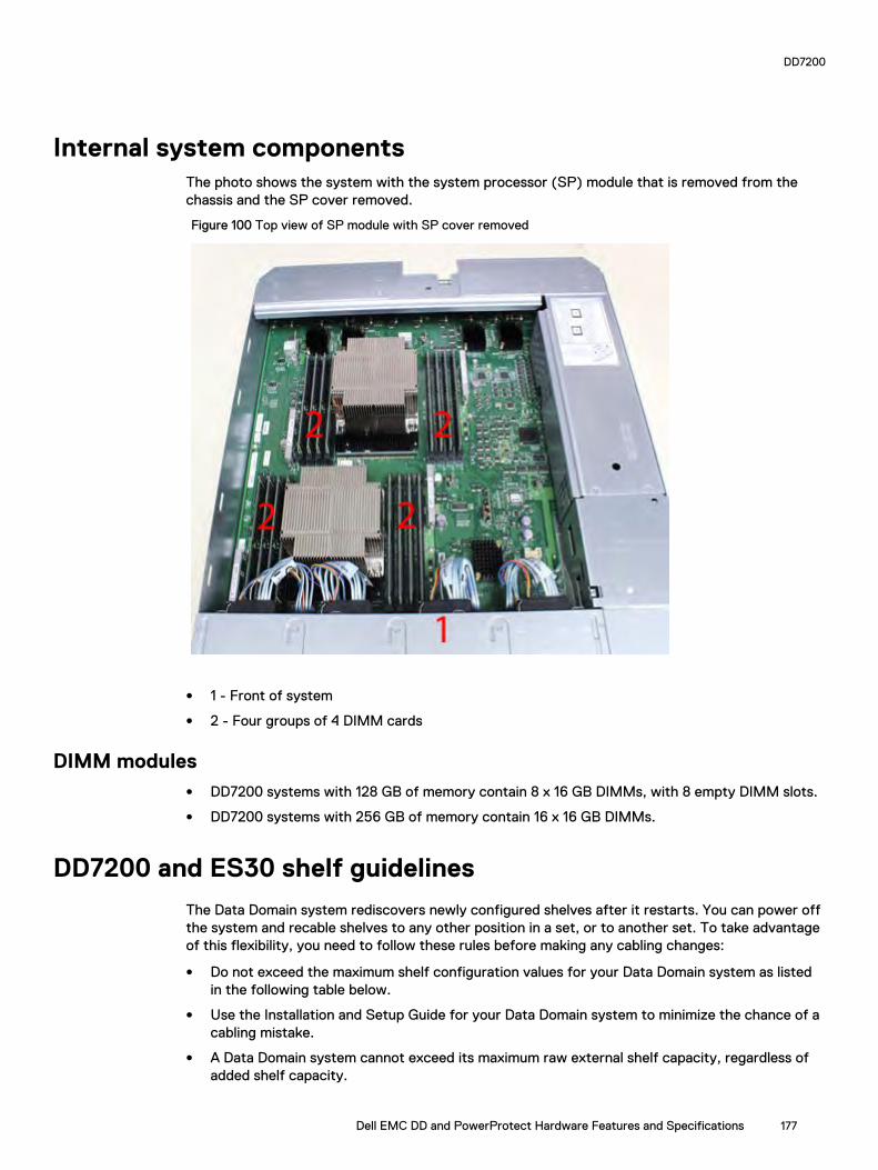
Internal system componentsThe photo shows the system with the system processor (SP) module that is removed from thechassis and the SP cover removed.
Figure 100 Top view of SP module with SP cover removed
l 1 - Front of system
l 2 - Four groups of 4 DIMM cards
DIMM modulesl DD7200 systems with 128 GB of memory contain 8 x 16 GB DIMMs, with 8 empty DIMM slots.
l DD7200 systems with 256 GB of memory contain 16 x 16 GB DIMMs.
DD7200 and ES30 shelf guidelines
The Data Domain system rediscovers newly configured shelves after it restarts. You can power offthe system and recable shelves to any other position in a set, or to another set. To take advantageof this flexibility, you need to follow these rules before making any cabling changes:
l Do not exceed the maximum shelf configuration values for your Data Domain system as listedin the following table below.
l Use the Installation and Setup Guide for your Data Domain system to minimize the chance of acabling mistake.
l A Data Domain system cannot exceed its maximum raw external shelf capacity, regardless ofadded shelf capacity.
DD7200
Dell EMC DD and PowerProtect Hardware Features and Specifications 177

l ES30 SATA shelves must be on their own chain.
Note:
l ES30 SAS shelves must be running DD OS 5.4 or later.
l ES30-45 SATA shelves must be running DD OS 5.4 or later.
l DD OS 5.7 and later support 4TB drives.
Table 105 DD7200 and ES30 shelf configuration
DD system Memoryrequired(GB)
SAS cards/port percard
ES30support(TB)
Maxshelvesper set
Maxnumber ofsets
Max externalcapacityavailable (TB)1
Max RAWexternalcapacity(TB) 2
DD7200 128 2x4 SAS 30,45; SATA15, 30,453
54 4 192 256
DD7200 256 2x4 SAS 30,45, 60;SATA 15,30, 453
54 4 384 540
DD7200 ER5, 6 256 4x4 SAS 30,45, 60;SATA 15,30, 453
7 8 768 1024
DD7200 w/ DDCloud Tier7
256 2x4 SAS 30,45, 60;SATA 15,30, 453
54 4 384 (max),additional 192SAS dedicatedto DD CloudTier
512 (max),additional 240SASdedicated toDD Cloud Tier
1. This figure only counts drives that have user data in the shelves.
2. The raw capacity of an ES30 is 125% of the available capacity.
3. ES30-45 (SATA) is only supported with DD OS 5.4 or later.
4. 5 shelves maximum with ES30, 4 is the recommended maximum. 4 shelves maximum with ES20, 3 is the recommended
maximum.
5. With Extended Retention software.
6. The maximum shelf count for any specific drive/shelf size might be less than the product of max shelves x max shelves per set.
7. Only available with DD OS 6.0.
Single phase power connections for 40U-P (current racks)The following figures show single phase power connections for several Data Domain systems.
DD7200
178 Dell EMC DD and PowerProtect Hardware Features and Specifications

Figure 101 Single phase power connections for DD4200, DD4500, and DD7200 systems
DD7200
Dell EMC DD and PowerProtect Hardware Features and Specifications 179

Cabling shelves
Note:
l Before cabling the shelves, physically install all shelves in the racks. Refer to the rail kitinstallation instructions included with the ES30 shelf for rack mounting.
l The documentation refers to two SAS HBAs. If only one HBA is allowed in a system, thenuse another port as defined later for that specific system.
l On an HA system, add cables from the second node to open ports at the end of the sets.The ports on the second node must connect to the same sets as the corresponding portson the first node.
Ports on the system’s SAS HBA cards connect directly to a shelf controller’s host port. Forredundancy, you need to create dual paths by using a port on one SAS HBA card to connect to oneshelf controller in each shelf set, and a port on another SAS HBA card to connect to another shelfcontroller in the same shelf set. With dual paths, if one SAS HBA card fails, the shelf is stilloperational. However, in the unlikely event any single shelf becomes completely disconnected frompower or SAS cables and becomes disconnected from a previously operational shelf, the filesystem goes down and the shelf is not operational. This is considered a double failure.
There are two kinds of configurations: one shelf in a set or multiple shelves in a set.
ES30 and DD7200 cablingThere are a few rules that must be followed when adding a mixture of ES20, ES30 SATA, andES30 SAS shelves to your system. If a system does not follow ALL of these rules it is not alegitimate configuration.
Prerequisites:
l Follow the minimum and maximum shelf capacity configuration provided in the table.
l You cannot have ES20 and ES30 shelves in the same set.
l You cannot have ES30 SATA and ES30 SAS shelves in the same set.
l You cannot exceed the maximum amount of raw capacity displayed in the product's cablingtable.
l The maximum number of shelves displayed in the product's cabling table cannot be exceeded.
l You cannot have more than four ES20s in a single set (maximum preference is three).
l You cannot have more than five ES30s in a single set (maximum preference is four).
l You can have a maximum of seven ES30s for systems with Extended Retention software.
l There are no specific placement or cabling requirements for the metadata shelves for DD CloudTier configurations. These shelves can be installed and cabled the same way as standard ES30shelves.
Note: An ES20 requires more power than an ES30. Ensure that your rack is configured tohandle the power needs.
The tables below show how to configure a mixed system. To use the tables, go to the appropriatesystem. Then find the number of ES20s that are to be configured in the first column. The nextcolumn defines the number of ES20 sets. If there are multiple rows with the same number ofES20s then pick the row with the appropriate number of ES20 SATA shelves. The next column inthat row defines the number of sets of ES30 SATA shelves. Finally, there may be entries for thenumber of desired ES30 SAS shelves and the number of sets to be used.
If the combinations of shelves exceed the supported usable storage, there may not be an entry.The entries are based on the smallest usable storage per shelf type (12TB for ES20, 12 TB for
DD7200
180 Dell EMC DD and PowerProtect Hardware Features and Specifications
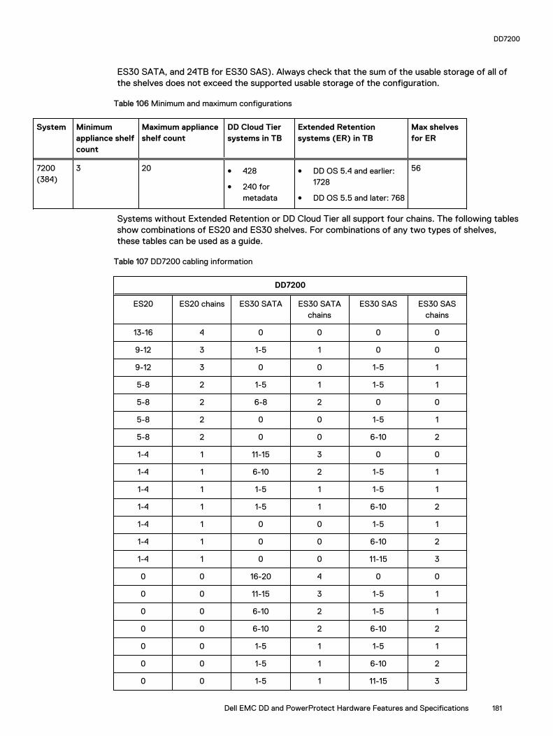
ES30 SATA, and 24TB for ES30 SAS). Always check that the sum of the usable storage of all ofthe shelves does not exceed the supported usable storage of the configuration.
Table 106 Minimum and maximum configurations
System Minimumappliance shelfcount
Maximum applianceshelf count
DD Cloud Tiersystems in TB
Extended Retentionsystems (ER) in TB
Max shelvesfor ER
7200(384)
3 20 l 428
l 240 formetadata
l DD OS 5.4 and earlier:1728
l DD OS 5.5 and later: 768
56
Systems without Extended Retention or DD Cloud Tier all support four chains. The following tablesshow combinations of ES20 and ES30 shelves. For combinations of any two types of shelves,these tables can be used as a guide.
Table 107 DD7200 cabling information
DD7200
ES20 ES20 chains ES30 SATA ES30 SATAchains
ES30 SAS ES30 SASchains
13-16 4 0 0 0 0
9-12 3 1-5 1 0 0
9-12 3 0 0 1-5 1
5-8 2 1-5 1 1-5 1
5-8 2 6-8 2 0 0
5-8 2 0 0 1-5 1
5-8 2 0 0 6-10 2
1-4 1 11-15 3 0 0
1-4 1 6-10 2 1-5 1
1-4 1 1-5 1 1-5 1
1-4 1 1-5 1 6-10 2
1-4 1 0 0 1-5 1
1-4 1 0 0 6-10 2
1-4 1 0 0 11-15 3
0 0 16-20 4 0 0
0 0 11-15 3 1-5 1
0 0 6-10 2 1-5 1
0 0 6-10 2 6-10 2
0 0 1-5 1 1-5 1
0 0 1-5 1 6-10 2
0 0 1-5 1 11-15 3
DD7200
Dell EMC DD and PowerProtect Hardware Features and Specifications 181

Table 107 DD7200 cabling information (continued)
DD7200
0 0 0 0 1-4 1
0 0 0 0 5-8 2
0 0 0 0 9-12 3
0 0 0 0 13-16/18 4
The following figures show cabling for base systems, systems with the Extended Retentionsoftware option, and systems integrated with an Avamar system.
Figure 102 Recommended DD7200 cabling
DD7200
182 Dell EMC DD and PowerProtect Hardware Features and Specifications
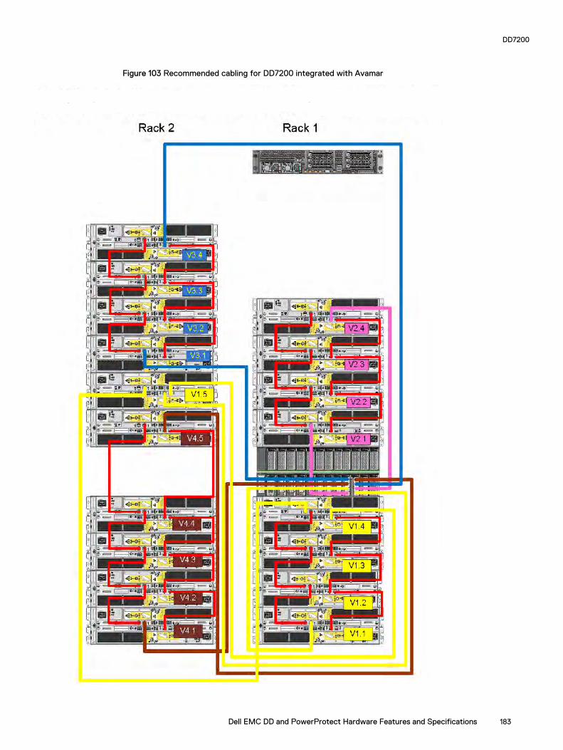
Figure 103 Recommended cabling for DD7200 integrated with Avamar
DD7200
Dell EMC DD and PowerProtect Hardware Features and Specifications 183

Figure 104 Recommended cabling for DD7200 with extended retention software or DD Cloud Tier
DD7200
184 Dell EMC DD and PowerProtect Hardware Features and Specifications

Figure 105 Recommended cabling for DD7200 with extended retention and integrated with Avamar
DD7200
Dell EMC DD and PowerProtect Hardware Features and Specifications 185

DD7200 and DS60 shelf guidelines
The Data Domain system rediscovers newly configured shelves after it restarts. You can power offthe system and recable shelves to any other position in a set, or to another set. To take advantageof this flexibility, you need to follow these rules before making any cabling changes:
l Do not exceed the maximum shelf configuration values for your Data Domain system as listedin the following table.
l For redundancy, the two connections from a Data Domain system to a set of shelves must useports on different SAS I/O modules.
l Use the Installation and Setup Guide for your Data Domain system to minimize the chance of acabling mistake.
l A Data Domain system cannot exceed its maximum raw external shelf capacity, regardless ofadded shelf capacity.
l ES30 SATA shelves must be on their own chain.
l If ES30 SAS shelves are on the same chain as a DS60, the maximum number of shelves on thatchain is 5.
l DD OS 5.7.1 does not support HA with SATA drives.
Table 108 DD7200 and DS60 shelf configuration
DD system Memoryrequired(GB)
SAScards/port percard
DS60 support(TB)
Maxshelvesper set
Maxnumber ofsets
Maxexternalcapacityavailable(TB)1
Max RAWexternalcapacity(TB)
DD7200 128 2x4 SAS 45 2 4 288 360
DD7200 256 2x4 SAS 45, 60 2 4 432 540
DD7200 ER 2 256 4x4 SAS 45, 60 2 8 864 1080
Note: An entry of 45 corresponds to DS60-3 models and an entry of 60 corresponds toDS60-4 models.
1. This column only counts drives that have user data in the shelves. For example, a DS60 4-240 has 192TB.
2. With Extended Retention software.
Single phase power connections for 40U-P (current racks)The following figures show single phase power connections for several Data Domain systems.
DD7200
186 Dell EMC DD and PowerProtect Hardware Features and Specifications

Figure 106 Single phase power connections for DD4200, DD4500, and DD7200 systems
DD7200
Dell EMC DD and PowerProtect Hardware Features and Specifications 187
3-phase power connections for 40U-P (current racks)Some environments use 3-phase power for 40U-P racks used for several Data Domain systems. Inthose situations it is desirable to balance the current draw across all 3 phases. The recommended3-phase power cabling attempts to do that, but an optimal configuration is dependent on thespecific installation. The following figures show recommended 3-phase power connections forseveral Data Domain systems.
Note: The next few diagrams show recommended 3-phase delta power connections.
DD7200
188 Dell EMC DD and PowerProtect Hardware Features and Specifications

Figure 107 3-phase delta power connections for DS60 expansion shelves (full-racked)
DD7200
Dell EMC DD and PowerProtect Hardware Features and Specifications 189
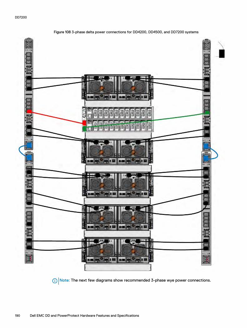
Figure 108 3-phase delta power connections for DD4200, DD4500, and DD7200 systems
Note: The next few diagrams show recommended 3-phase wye power connections.
DD7200
190 Dell EMC DD and PowerProtect Hardware Features and Specifications

Figure 109 3-phase wye power connections for DS60 expansion shelves (full-racked)
DD7200
Dell EMC DD and PowerProtect Hardware Features and Specifications 191

Figure 110 3-phase wye power connections for DD4200, DD4500, and DD7200 systems
DD7200
192 Dell EMC DD and PowerProtect Hardware Features and Specifications

DS60 and DD7200 cablingThere are a few rules that must be followed when adding a mixture of DS60 and other shelf typesto your system.
CAUTION If a system does not follow all these rules, it is not a legitimate configuration.
Prerequisites:
l You cannot exceed the maximum amount of usable capacity displayed in cabling table for eachsystem.
l You cannot exceed the maximum number of shelves displayed in cabling table for each system.
l You cannot connect more than two DS60 shelves in a single set.
Table 109 Minimum and maximum configurations
System Appliance maximum Minimum appliance shelf count
DD7200 384 TB 1
Mixing DS60, ES30, and ES20 shelves:
The non-Extended Retention versions of these systems all support four chains.
Extra planning and reconfiguration may be required to add DS60 shelves to system with ES20shelves, ES30 SATA shelves, or a combination of shelves.
l The ES20 shelves must be on their own set. Minimize the ES20 set count by combining up tofour ES20s per set.
l ES30 SATA shelves must also be on their own sets. Minimize the ES30 set count by combiningup to five ES30s per set. If required, combine up to seven ES30 SAS shelves per set tominimize the set count.
l A set can contain a maximum of two DS60 shelves and, if required because of otherrestrictions, add ES30 SAS shelves up to a maximum of five shelves in that set.
Note: The configuration rules apply also to Extended Retention systems.
The following figures show cabling for base systems and systems with the Extended Retentionsoftware.
Note: It is recommended that the DS60 shelf with the greater number of drives should alwaysbe placed in the bottom position.
DD7200
Dell EMC DD and PowerProtect Hardware Features and Specifications 193

Figure 111 Recommended cabling for DD7200 (3TB drives)
DD7200
194 Dell EMC DD and PowerProtect Hardware Features and Specifications
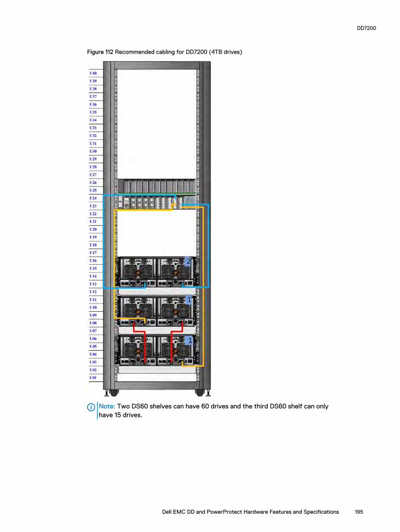
Figure 112 Recommended cabling for DD7200 (4TB drives)
Note: Two DS60 shelves can have 60 drives and the third DS60 shelf can onlyhave 15 drives.
DD7200
Dell EMC DD and PowerProtect Hardware Features and Specifications 195

Figure 113 Recommended cabling for DD7200 (3TB drives) with Extended Retention software
DD7200
196 Dell EMC DD and PowerProtect Hardware Features and Specifications
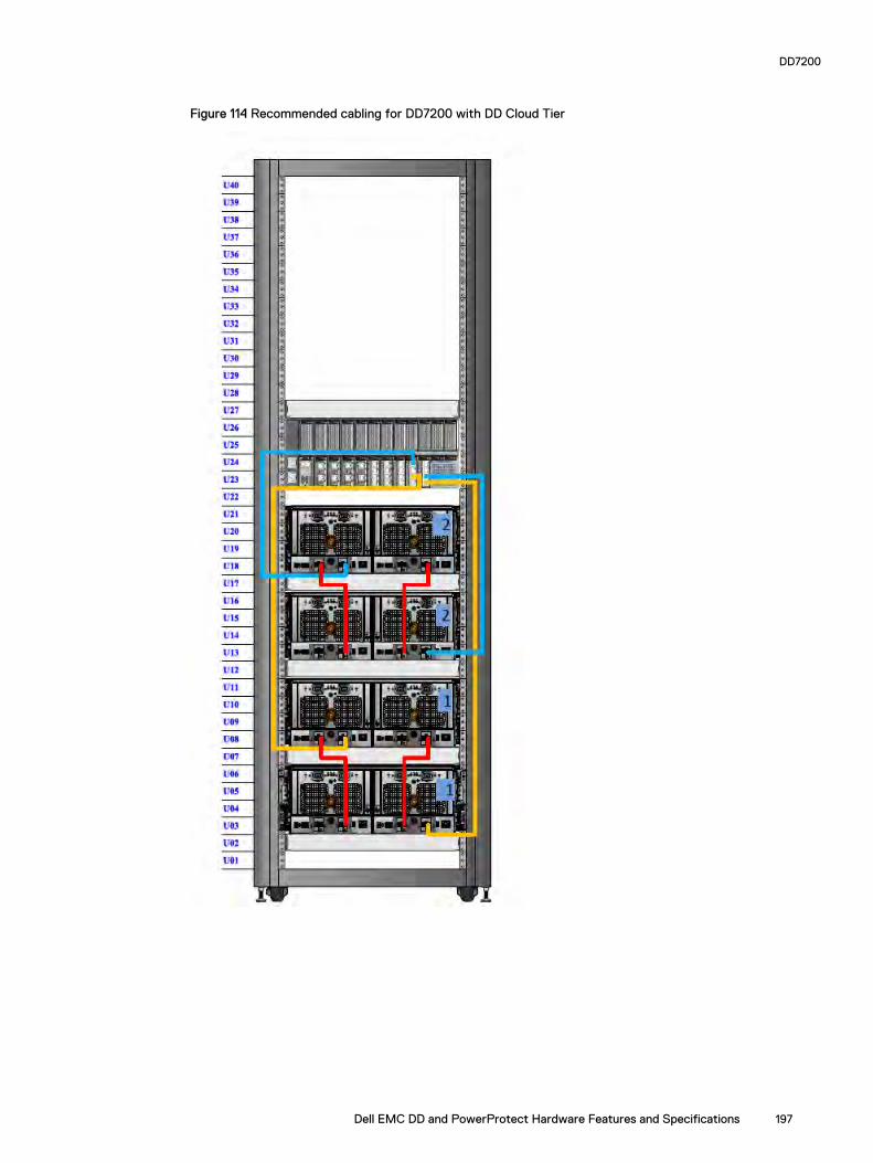
Figure 114 Recommended cabling for DD7200 with DD Cloud Tier
DD7200
Dell EMC DD and PowerProtect Hardware Features and Specifications 197

Figure 115 Recommended cabling for DD7200 (4TB drives) with Extended Retention software
Note: Four DS60 shelves have 60 drives each and two DS60 shelves have 15drives each.
DD7200
198 Dell EMC DD and PowerProtect Hardware Features and Specifications
CHAPTER 8
DD9300
This chapter contains the following topics:
l system features.................................................................................................................. 200l system specifications...........................................................................................................201l DD9300 storage capacity.....................................................................................................201l DD9300 front panel.............................................................................................................202l Back panel...........................................................................................................................204l I/O modules.........................................................................................................................207l Internal system components................................................................................................ 210l DD9300 and ES30 shelf guidelines....................................................................................... 211l DD9300 and DS60 shelf guidelines...................................................................................... 214
Dell EMC DD and PowerProtect Hardware Features and Specifications 199

system features
Table 110 system features
Feature (Baseconfiguration)
(Expandedconfiguration)
Rack height 2U 2U
Processor E5-2680 V3 E5-2680 V3
Kernel 3.2.x 3.2.x
NVRAM
Memory 4 x 32 GB DIMM +4 x 16 GB DIMM(192 GB)
8 x 32 GB DIMM +8 x 16 GB DIMM(384 GB)
Internal drives HDDs in 3.5" bays 4 4
SSDs in 3.5" bays 5 8
SSDs in 2.5" bays 0 0
I/O module slots SAS I/O modules () 2 2
Network and FC I/O modules Four replaceableI/O module slots.Not hot-swappable.
Four replaceableI/O module slots.Not hot-swappable.
Supported capacity Non-extended retention 384 TB 720 TB
DD Cloud Tier N/A 1440 TB a
Extended retention N/A 720 TBb
High availability support Yes Yes
HA private interconnect (2) 10GBase-Tports
(2) 10GBase-Tports
External SSD shelf One SSD shelf forA-P highavailability clustercontaining twodrives.
One SSD shelf forA-P highavailability clustercontaining fourdrives.
SAS string depth(max)
ES30 6 6 (7 for extendedretention)
DS60 3 3
ES30 and DS60 5 shelves total 5 shelves total
Stream count 810 writes, 225reads
810 writes, 225reads
a. DD Cloud Tier requires four ES30 shelves fully populated with 4 TB drives to store DD CloudTier metadata.
b. Extended retention not available on HA configurations
DD9300
200 Dell EMC DD and PowerProtect Hardware Features and Specifications

system specifications
Table 111 system specifications
Model Averagepowerconsumption25 C
Heat dissipation(operatingmaximum)
Weight a Width Depth Height
645W 1.69 x 10⁶ J/hr(1604 Btu/hr)maximum
70 lbs (31.75kg)
17.50 in(44.45 cm)
30.5 in (77.5cm)
3.40 in (8.64cm)
a. The weight does not include mounting rails. Allow 2.3-4.5 kg (5-10 lb) for a rail set.
Table 112 System operating environment
Requirement Description
Ambient temperature 10°C - 35°C; derate 1.1°C per 1,000 ft (304m)
Relative humidity (extremes) 20–80% noncondensing
Elevation 0 - 7,500ft (0 - 2,268m)
Operating acoustic noise Lwad sound power, 7.5 Bels
DD9300 storage capacity
The following table provides storage capacity information for the DD9300 system.
Table 113 DD9300 storage capacity
Memory Internaldisks(systemdisks only)
Externalstorage(raw)
Usable data storage space (TB/TiB/GB/GiB)a
192 GB(Base)
l 4 x 4 TBHDD
l 5 x 800GB SSD
480 TBb 384 TB 349.2 TiB 384,000 GB 357,628 GiB
384 GB(Expanded)
l 4 x 4 TBHDD
l 8 x 800GB SSD
l ActiveTier: 900TBb
l ArchiveTier: 900TBc
l CloudTier:
l ActiveTier: 720TB
l ArchiveTier: 720TB
l CloudTier:1,440 TB
l Active Tier:654.8 TiB
l Archive Tier:654.8 TiB
l Cloud Tier:1,309.6 TiB
l Active Tier:720,000 GB
l Archive Tier:720,000 GB
l Cloud Tier:144,000 GB
l Active Tier:670,552 GiB
l Archive Tier:670,552 GiB
l Cloud Tier:1,341,104GiB
DD9300
Dell EMC DD and PowerProtect Hardware Features and Specifications 201
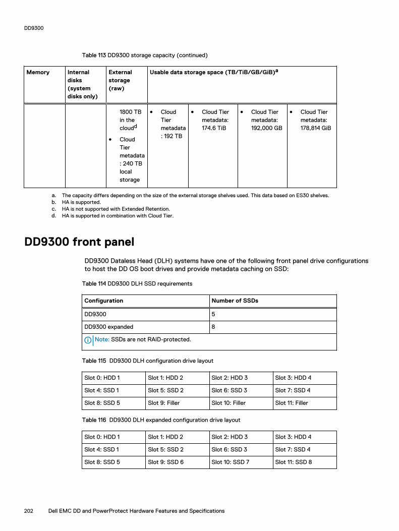
Table 113 DD9300 storage capacity (continued)
Memory Internaldisks(systemdisks only)
Externalstorage(raw)
Usable data storage space (TB/TiB/GB/GiB)a
1800 TBin thecloudd
l CloudTiermetadata: 240 TBlocalstorage
l CloudTiermetadata: 192 TB
l Cloud Tiermetadata:174.6 TiB
l Cloud Tiermetadata:192,000 GB
l Cloud Tiermetadata:178,814 GiB
a. The capacity differs depending on the size of the external storage shelves used. This data based on ES30 shelves.b. HA is supported.c. HA is not supported with Extended Retention.d. HA is supported in combination with Cloud Tier.
DD9300 front panel
DD9300 Dataless Head (DLH) systems have one of the following front panel drive configurationsto host the DD OS boot drives and provide metadata caching on SSD:
Table 114 DD9300 DLH SSD requirements
Configuration Number of SSDs
DD9300 5
DD9300 expanded 8
Note: SSDs are not RAID-protected.
Table 115 DD9300 DLH configuration drive layout
Slot 0: HDD 1 Slot 1: HDD 2 Slot 2: HDD 3 Slot 3: HDD 4
Slot 4: SSD 1 Slot 5: SSD 2 Slot 6: SSD 3 Slot 7: SSD 4
Slot 8: SSD 5 Slot 9: Filler Slot 10: Filler Slot 11: Filler
Table 116 DD9300 DLH expanded configuration drive layout
Slot 0: HDD 1 Slot 1: HDD 2 Slot 2: HDD 3 Slot 3: HDD 4
Slot 4: SSD 1 Slot 5: SSD 2 Slot 6: SSD 3 Slot 7: SSD 4
Slot 8: SSD 5 Slot 9: SSD 6 Slot 10: SSD 7 Slot 11: SSD 8
DD9300
202 Dell EMC DD and PowerProtect Hardware Features and Specifications

Front LED indicatorsThe front of the system contain 12 disk drive status LEDs that are normally blue, and blink whenthere is activity on the disk. The LEDs are shaped like triangles, and the apex of the triangle pointsleft or right, indicating that disk's status. If the disk drive has a failure, the disk’s status LED turnsfrom blue to amber, indicating that a drive must be replaced.
The front also contains two system status LEDs. A blue system power LED is present that is onwhenever the system has power. An amber system fault LED is also present that is normally offand lit amber whenever the chassis or any other FRU in the system requires service.
Figure 116 Front LED indicators
1. System service LED2. Drive activity/service LED3. System power LED
Table 117 Front LEDs
Name Color Purpose
System power LED Blue Indication that the system haspower.
System service LED Amber Normally off; is lit amberwhenever the SP or any otherFRU (except disk drives) inthe system requires service.
Drive activity/Service LED Blue /Amber l Lit blue when the drive ispowered.
l Blinks blue during driveactivity.
l Lit solid amber when adisk needs service.
DD9300
Dell EMC DD and PowerProtect Hardware Features and Specifications 203

Back panelThe back panel of the chassis contains the following components:
1. Management panel
2. Not Used -- Two 2.5" SSD slots labeled 0 and 1
3. I/O module slots
4. Power supply modules (PSU 0 is the lower module, and PSU 1 is the upper module)
Rear LED indicatorsFigure 117 Rear LED indicators
1. Do not remove LED2. SP service LED3. System power LED4. AC power good LED5. DC power good LED6. Power supply fault LED
Name of LED Location Color Definition
"Do not remove" LED Upper left-most partof rear chassis
White This LED is lit duringsystem BIOS andBMC firmwareupdates and indicatesthat the SP shouldnot be removed fromthe chassis, norshould system powerbe removed.
SP service LED To the right of "Donot remove" LED
Amber l Solid amber - SPor a FRU inside
DD9300
204 Dell EMC DD and PowerProtect Hardware Features and Specifications

Name of LED Location Color Definition
the SP requiresservice
l Blinking amber -blink rate reflectsone of thefollowing isbooting
n BIOS - 1/4 Hz
n POST - 1 Hz
n OS - 4 Hz
Drive Power/ActivityLED a
Left LED on the SSD Blue Lit blue when thedrive is powered.Blinks during driveactivity.
Drive Fault LED a Right LED on the SSD Amber Lit solid amber when adrive needs service.
System power LED Right-most LED onthe managementpanel
Blue SP has good, stablepower
PSU FRU LED - ACGood
Top LED on powersupply
Green AC input is asexpected
PSU FRU LED - DCGood
Middle LED on powersupply
Green DC output is asexpected
PSU FRU LED -Attention
Bottom LED on powersupply
Amber PSU has encountereda fault condition
a. The SSD is only present on DD6300 systems.
DD9300
Dell EMC DD and PowerProtect Hardware Features and Specifications 205
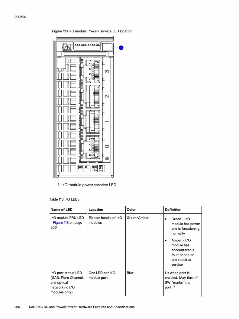
Figure 118 I/O module Power/Service LED location
1. I/O module power/service LED
Table 118 I/O LEDs
Name of LED Location Color Definition
I/O module FRU LED- Figure 118 on page206
Ejector handle of I/Omodules
Green/Amber l Green - I/Omodule has powerand is functioningnormally
l Amber - I/Omodule hasencountered afault conditionand requiresservice
I/O port status LED(SAS, Fibre Channel,and opticalnetworking I/Omodules only)
One LED per I/Omodule port
Blue Lit when port isenabled. May flash ifSW "marks" theport. a
DD9300
206 Dell EMC DD and PowerProtect Hardware Features and Specifications

Table 118 I/O LEDs (continued)
a. For RJ45 networking ports, the standard green link and amber activity LEDs are used.
Figure 119 Onboard network port LEDs
1. Network port link LED2. Network port activity LED3. Dedicated IPMI port BMC0A4. Management interface EthMa
Table 119 Onboard network port LEDs
Name of LED Location Color Definition
Onboard network portLED - Link LED Figure119 on page 207
Top LED on networkport
Green l Lit when there isa link at1000BaseT and100BaseT speeds
l Off when the linkspeed is 10BaseTor there is no link
Onboard network portLED - Activity LED
Bottom LED onnetwork port
Amber Blinks when there istraffic on the port
I/O modulesI/O module slot numbering
The eight I/O module slots are enumerated as Slot 0 (on the left when viewed from the rear)through Slot 7. Ports on an I/O module are enumerated as 0 through 3, with 0 being on thebottom.
Figure 120 I/O module slot numbering
DD9300
Dell EMC DD and PowerProtect Hardware Features and Specifications 207
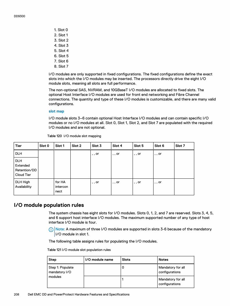
1. Slot 02. Slot 13. Slot 24. Slot 35. Slot 46. Slot 57. Slot 68. Slot 7
I/O modules are only supported in fixed configurations. The fixed configurations define the exactslots into which the I/O modules may be inserted. The processors directly drive the eight I/Omodule slots, meaning all slots are full performance.
The non-optional SAS, NVRAM, and 10GBaseT I/O modules are allocated to fixed slots. Theoptional Host Interface I/O modules are used for front end networking and Fibre Channelconnections. The quantity and type of these I/O modules is customizable, and there are many validconfigurations.
slot map
I/O module slots 3–6 contain optional Host Interface I/O modules and can contain specific I/Omodules or no I/O modules at all. Slot 0, Slot 1, Slot 2, and Slot 7 are populated with the requiredI/O modules and are not optional.
Table 120 I/O module slot mapping
Tier Slot 0 Slot 1 Slot 2 Slot 3 Slot 4 Slot 5 Slot 6 Slot 7
DLH , , or , , or , , or , , or
DLHExtendedRetention/DDCloud Tier
DLH HighAvailability
for HAinterconnect
, , or , , or , , or , , or
I/O module population rulesThe system chassis has eight slots for I/O modules. Slots 0, 1, 2, and 7 are reserved. Slots 3, 4, 5,and 6 support host interface I/O modules. The maximum supported number of any type of hostinterface I/O module is four.
Note: A maximum of three I/O modules are supported in slots 3-6 because of the mandatory I/O module in slot 1.
The following table assigns rules for populating the I/O modules.
Table 121 I/O module slot population rules
Step I/O module name Slots Notes
Step 1: Populatemandatory I/Omodules
0 Mandatory for allconfigurations
1 Mandatory for allconfigurations
DD9300
208 Dell EMC DD and PowerProtect Hardware Features and Specifications

Table 121 I/O module slot population rules (continued)
Step I/O module name Slots Notes
2 Mandatory for allconfigurations
7 Mandatory for allconfigurations
Step 2: Populate all I/O modules
3, 4, 5, 6 Populate startingfrom the lowestavailable slot number.
Step 3: Populate all I/O modules
3, 4, 5, 6 Populate startingfrom the lowestavailable slot number.With in slot 1, maxnumber of I/Omodules are limited to4.
Step 4: Populate all I/O modules
6, 5, 4, 3 Populate startingfrom the highestavailable slot number.
DD9300
Dell EMC DD and PowerProtect Hardware Features and Specifications 209

Internal system componentsThe following figure shows the layout of the CPUs and DIMMs inside the chassis. The front of thesystem is at the top of the figure.
Figure 121 CPU and memory locations
DIMMs overviewDual in-line memory modules (DIMM) come in various sizes, which must be configured in a certainway. This topic can help you select the correct configuration when servicing DIMMs.
The storage processor contains two Intel processors each with an integrated memory controllerthat supports four channels of memory. The storage processor allows two DIMM slots per channel,so the storage processor supports a total of 16 DIMM slots.
memory DIMM configuration
Table 122 memory DIMM configuration
Tier Total Memory Memory DIMM Configuration
DLH Expanded 384 GB 8 x 32 GB + 8 x 16 GB
DLH 192 GB 4 x 32 GB + 4 x 16 GB
DLH Extended Retention/DDCloud Tier
384 GB 8 x 32 GB +8 x 16 GB
HA is supported with all available memory configurations.
To ensure maximum memory performance, there are memory DIMM population rules for bestmemory loading and interleaving. Table 123 on page 210 and Table 124 on page 211 specify theDIMM location rules for various memory configurations:
Table 123 Memory locations - CPU 0
Channel A Channel B Channel D Channel C
Tier TotalMemory
0 1 2 3 4 5 6 7
DLHExpanded
384 GB 32 GB 16 GB 32 GB 16 GB 16 GB 32 GB 16 GB 32 GB
DLH 192 GB 16 GB N/A 16 GB N/A N/A 32 GB N/A 32 GB
DD9300
210 Dell EMC DD and PowerProtect Hardware Features and Specifications
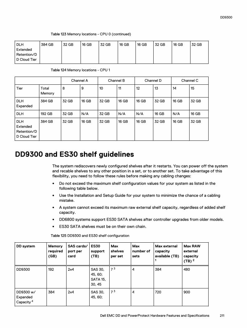
Table 123 Memory locations - CPU 0 (continued)
DLHExtendedRetention/DD Cloud Tier
384 GB 32 GB 16 GB 32 GB 16 GB 16 GB 32 GB 16 GB 32 GB
Table 124 Memory locations - CPU 1
Channel A Channel B Channel D Channel C
Tier TotalMemory
8 9 10 11 12 13 14 15
DLHExpanded
384 GB 32 GB 16 GB 32 GB 16 GB 16 GB 32 GB 16 GB 32 GB
DLH 192 GB 32 GB N/A 32 GB N/A N/A 16 GB N/A 16 GB
DLHExtendedRetention/DD Cloud Tier
384 GB 32 GB 16 GB 32 GB 16 GB 16 GB 32 GB 16 GB 32 GB
DD9300 and ES30 shelf guidelines
The system rediscovers newly configured shelves after it restarts. You can power off the systemand recable shelves to any other position in a set, or to another set. To take advantage of thisflexibility, you need to follow these rules before making any cabling changes:
l Do not exceed the maximum shelf configuration values for your system as listed in thefollowing table below.
l Use the Installation and Setup Guide for your system to minimize the chance of a cablingmistake.
l A system cannot exceed its maximum raw external shelf capacity, regardless of added shelfcapacity.
l DD6800 systems support ES30 SATA shelves after controller upgrades from older models.
l ES30 SATA shelves must be on their own chain.
Table 125 DD9300 and ES30 shelf configuration
DD system Memoryrequired(GB)
SAS cards/port percard
ES30support(TB)
Maxshelvesper set
Maxnumber ofsets
Max externalcapacityavailable (TB)1
Max RAWexternalcapacity(TB) 2
DD9300 192 2x4 SAS 30,45, 60;SATA 15,30, 45
7 3 4 384 480
DD9300 w/ExpandedCapacity 4
384 2x4 SAS 30,45, 60;
7 3 4 720 900
DD9300
Dell EMC DD and PowerProtect Hardware Features and Specifications 211

Table 125 DD9300 and ES30 shelf configuration (continued)
DD system Memoryrequired(GB)
SAS cards/port percard
ES30support(TB)
Maxshelvesper set
Maxnumber ofsets
Max externalcapacityavailable (TB)1
Max RAWexternalcapacity(TB) 2
SATA 15,30, 45
DD9300 w/ExpandedCapacity or w/HA 4
384 2x4 SAS 30,45, 60
7 3 4 720 900
DD9300 w/ ER 384 2x4 SAS 30,45, 60;SATA 15,30, 45
7 3 4 1440 1800
DD9300ExpandedCapacity w/Cloud Tier
384 2x4 SAS 30,45, 60;SATA 15,30, 45
7 3 4 720 (max),additional 192SAS dedicatedto Cloud Tier
900 (max),additional 240SASdedicated toCloud Tier
DD9300 w/ExpandedCapacity or w/HA and CloudTier 4
384 2x4 SAS 30,45, 60
7 3 4 720 (max),additional 192SAS dedicatedto Cloud Tier
900 (max),additional 240SASdedicated toCloud Tier
1. This figure only counts drives that have user data in the shelves.
2. The raw capacity of an ES30 is 125% of the available capacity.
3. Recommended configurations start at four shelves per set and expand beyond that as required. For HA configurations, the
counts as a shelf.
4. DDOS 6.x and greater and SSD shelf configuration
Types of cabinets and power connectionsThe ES30 chassis is installed in two types of racks: 40U-C (existing racks) and the 40U-P (newerracks). The racks use one phase or 3-phase power connections.
3-Phase power connections for 40U-P (current racks)
Some environments use 3-phase power for 40U-P racks that are used for several systems. Inthose situations, it is desirable to balance the current draw across all three phases. Therecommended 3-phase power cabling attempts to do that, but an optimal configuration dependson the specific installation.
Cabling shelves
Note:
l Before cabling the shelves, physically install all shelves in the racks. Refer to the rail kitinstallation instructions included with the ES30 shelf for rack mounting.
DD9300
212 Dell EMC DD and PowerProtect Hardware Features and Specifications
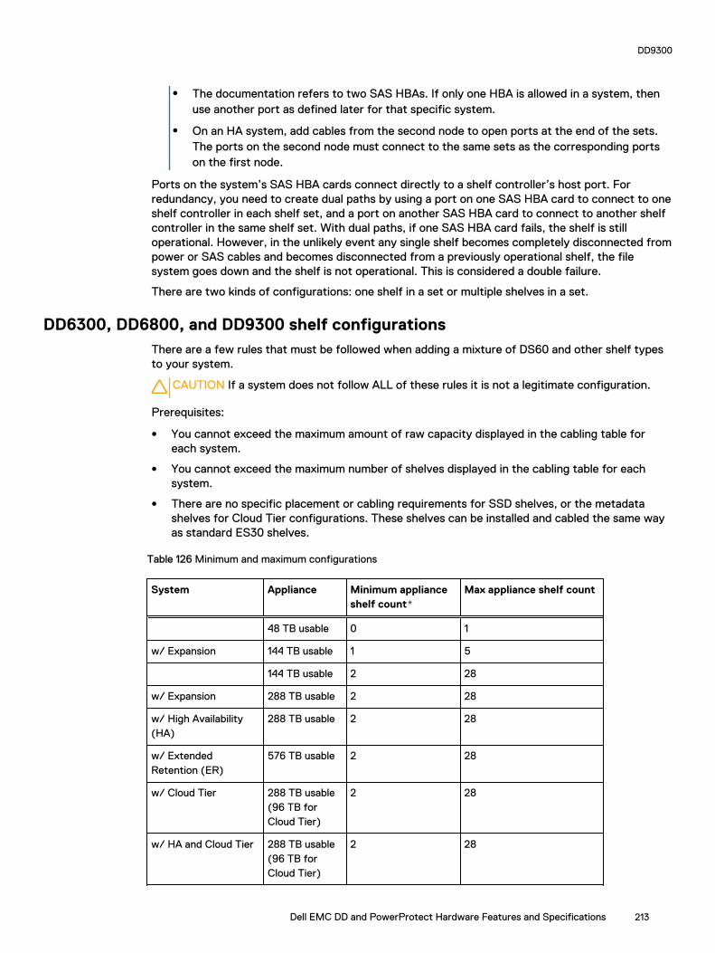
l The documentation refers to two SAS HBAs. If only one HBA is allowed in a system, thenuse another port as defined later for that specific system.
l On an HA system, add cables from the second node to open ports at the end of the sets.The ports on the second node must connect to the same sets as the corresponding portson the first node.
Ports on the system’s SAS HBA cards connect directly to a shelf controller’s host port. Forredundancy, you need to create dual paths by using a port on one SAS HBA card to connect to oneshelf controller in each shelf set, and a port on another SAS HBA card to connect to another shelfcontroller in the same shelf set. With dual paths, if one SAS HBA card fails, the shelf is stilloperational. However, in the unlikely event any single shelf becomes completely disconnected frompower or SAS cables and becomes disconnected from a previously operational shelf, the filesystem goes down and the shelf is not operational. This is considered a double failure.
There are two kinds of configurations: one shelf in a set or multiple shelves in a set.
DD6300, DD6800, and DD9300 shelf configurationsThere are a few rules that must be followed when adding a mixture of DS60 and other shelf typesto your system.
CAUTION If a system does not follow ALL of these rules it is not a legitimate configuration.
Prerequisites:
l You cannot exceed the maximum amount of raw capacity displayed in the cabling table foreach system.
l You cannot exceed the maximum number of shelves displayed in the cabling table for eachsystem.
l There are no specific placement or cabling requirements for SSD shelves, or the metadatashelves for Cloud Tier configurations. These shelves can be installed and cabled the same wayas standard ES30 shelves.
Table 126 Minimum and maximum configurations
System Appliance Minimum applianceshelf count*
Max appliance shelf count
48 TB usable 0 1
w/ Expansion 144 TB usable 1 5
144 TB usable 2 28
w/ Expansion 288 TB usable 2 28
w/ High Availability(HA)
288 TB usable 2 28
w/ ExtendedRetention (ER)
576 TB usable 2 28
w/ Cloud Tier 288 TB usable(96 TB forCloud Tier)
2 28
w/ HA and Cloud Tier 288 TB usable(96 TB forCloud Tier)
2 28
DD9300
Dell EMC DD and PowerProtect Hardware Features and Specifications 213
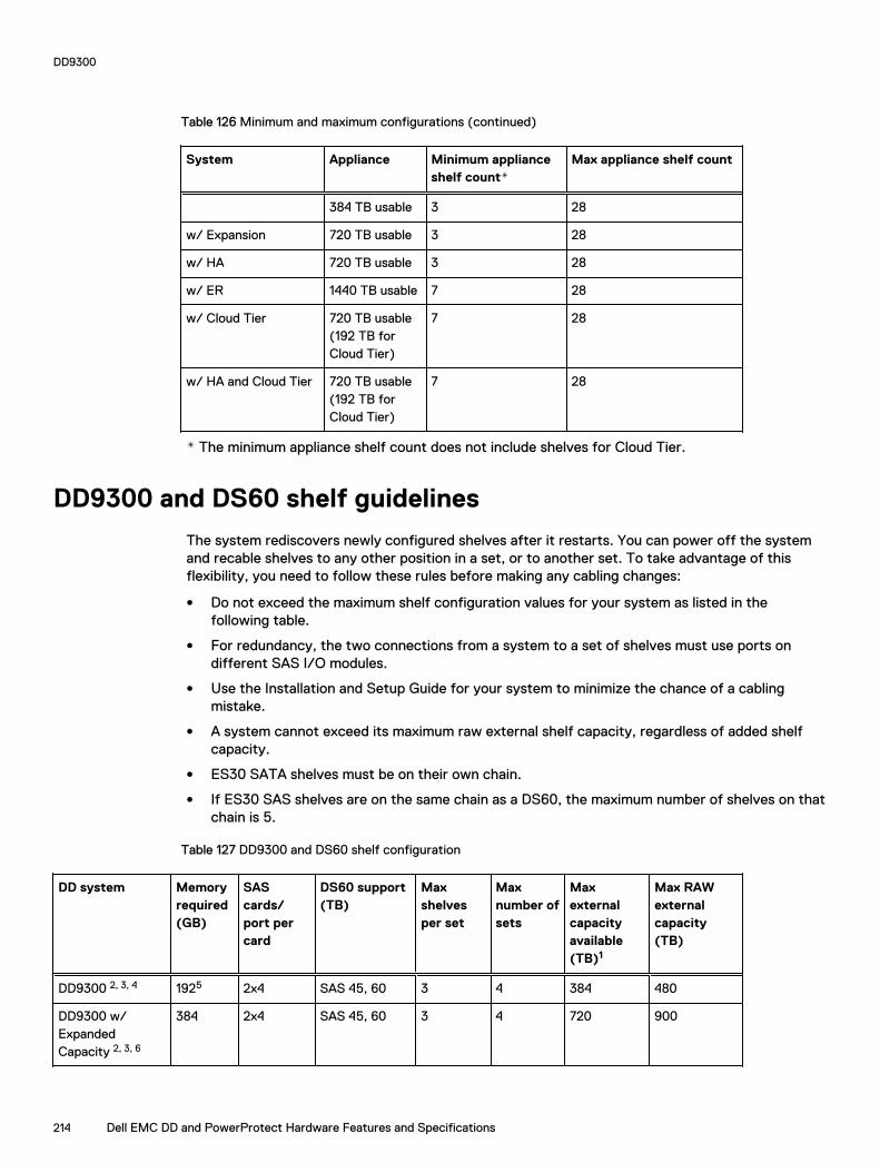
Table 126 Minimum and maximum configurations (continued)
System Appliance Minimum applianceshelf count*
Max appliance shelf count
384 TB usable 3 28
w/ Expansion 720 TB usable 3 28
w/ HA 720 TB usable 3 28
w/ ER 1440 TB usable 7 28
w/ Cloud Tier 720 TB usable(192 TB forCloud Tier)
7 28
w/ HA and Cloud Tier 720 TB usable(192 TB forCloud Tier)
7 28
* The minimum appliance shelf count does not include shelves for Cloud Tier.
DD9300 and DS60 shelf guidelines
The system rediscovers newly configured shelves after it restarts. You can power off the systemand recable shelves to any other position in a set, or to another set. To take advantage of thisflexibility, you need to follow these rules before making any cabling changes:
l Do not exceed the maximum shelf configuration values for your system as listed in thefollowing table.
l For redundancy, the two connections from a system to a set of shelves must use ports ondifferent SAS I/O modules.
l Use the Installation and Setup Guide for your system to minimize the chance of a cablingmistake.
l A system cannot exceed its maximum raw external shelf capacity, regardless of added shelfcapacity.
l ES30 SATA shelves must be on their own chain.
l If ES30 SAS shelves are on the same chain as a DS60, the maximum number of shelves on thatchain is 5.
Table 127 DD9300 and DS60 shelf configuration
DD system Memoryrequired(GB)
SAScards/port percard
DS60 support(TB)
Maxshelvesper set
Maxnumber ofsets
Maxexternalcapacityavailable(TB)1
Max RAWexternalcapacity(TB)
DD9300 2, 3, 4 1925 2x4 SAS 45, 60 3 4 384 480
DD9300 w/ExpandedCapacity 2, 3, 6
384 2x4 SAS 45, 60 3 4 720 900
DD9300
214 Dell EMC DD and PowerProtect Hardware Features and Specifications
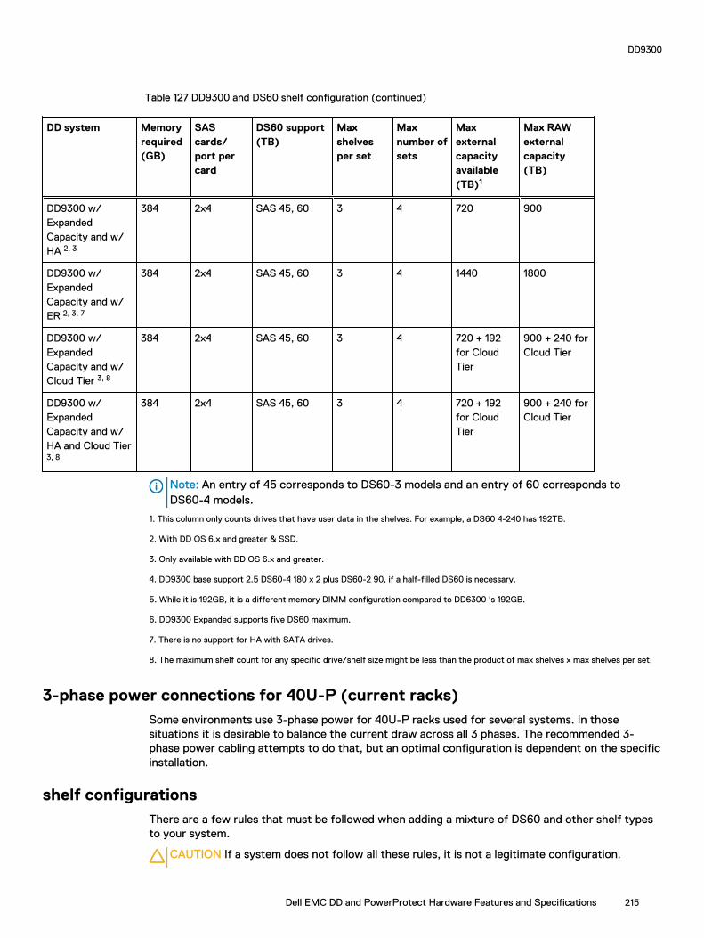
Table 127 DD9300 and DS60 shelf configuration (continued)
DD system Memoryrequired(GB)
SAScards/port percard
DS60 support(TB)
Maxshelvesper set
Maxnumber ofsets
Maxexternalcapacityavailable(TB)1
Max RAWexternalcapacity(TB)
DD9300 w/ExpandedCapacity and w/HA 2, 3
384 2x4 SAS 45, 60 3 4 720 900
DD9300 w/ExpandedCapacity and w/ER 2, 3, 7
384 2x4 SAS 45, 60 3 4 1440 1800
DD9300 w/ExpandedCapacity and w/Cloud Tier 3, 8
384 2x4 SAS 45, 60 3 4 720 + 192for CloudTier
900 + 240 forCloud Tier
DD9300 w/ExpandedCapacity and w/HA and Cloud Tier3, 8
384 2x4 SAS 45, 60 3 4 720 + 192for CloudTier
900 + 240 forCloud Tier
Note: An entry of 45 corresponds to DS60-3 models and an entry of 60 corresponds toDS60-4 models.
1. This column only counts drives that have user data in the shelves. For example, a DS60 4-240 has 192TB.
2. With DD OS 6.x and greater & SSD.
3. Only available with DD OS 6.x and greater.
4. DD9300 base support 2.5 DS60-4 180 x 2 plus DS60-2 90, if a half-filled DS60 is necessary.
5. While it is 192GB, it is a different memory DIMM configuration compared to DD6300 's 192GB.
6. DD9300 Expanded supports five DS60 maximum.
7. There is no support for HA with SATA drives.
8. The maximum shelf count for any specific drive/shelf size might be less than the product of max shelves x max shelves per set.
3-phase power connections for 40U-P (current racks)Some environments use 3-phase power for 40U-P racks used for several systems. In thosesituations it is desirable to balance the current draw across all 3 phases. The recommended 3-phase power cabling attempts to do that, but an optimal configuration is dependent on the specificinstallation.
shelf configurationsThere are a few rules that must be followed when adding a mixture of DS60 and other shelf typesto your system.
CAUTION If a system does not follow all these rules, it is not a legitimate configuration.
DD9300
Dell EMC DD and PowerProtect Hardware Features and Specifications 215

Prerequisites:
l You cannot exceed the maximum amount of raw capacity displayed in cabling table for eachsystem.
l You cannot exceed the maximum number of shelves displayed in cabling table for each system.
l You cannot connect more than three DS60 shelves in a single set.
Table 128 Minimum configurations
System Appliance maximum Minimum appliance DS60 shelfcount
144 TB 0
144 TB 2
w/ High Availability (HA) 288 TB 2 (plus 1 FS15 for SSD cache)
w/ Extended Retention (ER) 576 TB 2
w/ Cloud Tier 384 TB (96 TB forCloud Tier)
2 (plus 2 ES30s for Cloud Tier)
w/ HA and Cloud Tier 384 TB (96 TB forCloud Tier)
2 (plus 1 FS15 for SSD cache,and 2 ES30s for Cloud Tier)
384 TB 3
w/ HA 720 TB 3 (plus 1 FS15 for SSD cache)
w/ ER 1440 TB 3
w/ Cloud Tier 912 TB (192 TB forCloud Tier)
3 (plus 4 ES30s or 1 DS60 forCloud Tier)
w/ HA and Cloud Tier 912 TB (192 TB forCloud Tier)
4 (plus 1 FS15 for SSD cache,and 4 ES30s or 1 DS60 for CloudTier)
1. DS60 will only be partially filled.
l A Cloud Tier system shares the ERSO cabling configuration; however, Cloud Tier has a lowermaximum.
l It is recommended that the shelf with the greater number of drives should always be placed inthe bottom position.
l only supports one DS60.
l only has one SAS SLIC and all DS60 connections are made to that single SAS SLIC.
l only has one SAS SLIC and all DS60 connections are made to that single SAS SLIC.
DD9300
216 Dell EMC DD and PowerProtect Hardware Features and Specifications

CHAPTER 9
DD9400
This chapter contains the following topics:
l DD9400 system features..................................................................................................... 218l DD9400 system specifications.............................................................................................219l DD9400 storage capacity and configurations...................................................................... 220l DD9400 front panel..............................................................................................................221l DD9400 SSD usage and configurations............................................................................... 224l Rear panel........................................................................................................................... 225l PCIe HBAs...........................................................................................................................227l DD9400 DIMM configurations.............................................................................................229l DD6900, DD9400, and DD9900 storage shelves configurations and capacities...................229
Dell EMC DD and PowerProtect Hardware Features and Specifications 217
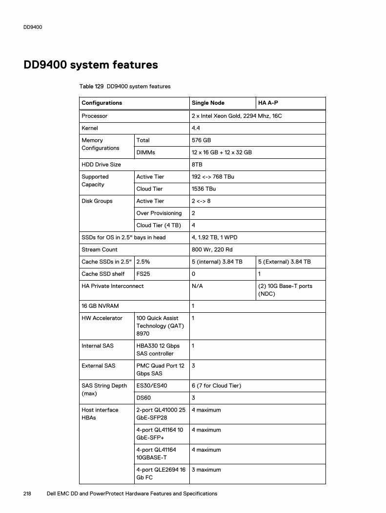
DD9400 system features
Table 129 DD9400 system features
Configurations Single Node HA A-P
Processor 2 x Intel Xeon Gold, 2294 Mhz, 16C
Kernel 4.4
MemoryConfigurations
Total 576 GB
DIMMs 12 x 16 GB + 12 x 32 GB
HDD Drive Size 8TB
SupportedCapacity
Active Tier 192 <-> 768 TBu
Cloud Tier 1536 TBu
Disk Groups Active Tier 2 <-> 8
Over Provisioning 2
Cloud Tier (4 TB) 4
SSDs for OS in 2.5" bays in head 4, 1.92 TB, 1 WPD
Stream Count 800 Wr, 220 Rd
Cache SSDs in 2.5" 2.5% 5 (internal) 3.84 TB 5 (External) 3.84 TB
Cache SSD shelf FS25 0 1
HA Private Interconnect N/A (2) 10G Base-T ports(NDC)
16 GB NVRAM 1
HW Accelerator 100 Quick AssistTechnology (QAT)8970
1
Internal SAS HBA330 12 GbpsSAS controller
1
External SAS PMC Quad Port 12Gbps SAS
3
SAS String Depth(max)
ES30/ES40 6 (7 for Cloud Tier)
DS60 3
Host interfaceHBAs
2-port QL41000 25GbE-SFP28
4 maximum
4-port QL41164 10GbE-SFP+
4 maximum
4-port QL4116410GBASE-T
4 maximum
4-port QLE2694 16Gb FC
3 maximum
DD9400
218 Dell EMC DD and PowerProtect Hardware Features and Specifications

Table 129 DD9400 system features (continued)
Configurations Single Node HA A-P
Network DaughterCard option
4-port QL41000 10GbE-SP+ FasLinQ
1
4-port QL4116410GBASE-T
1
DD9400 system specifications
Figure 122 System dimensions
Table 130 DD9400 system specifications
Xa Xb Y Za (withbezel)
Za (withoutbezel)
Zb Zc
482.0 mm(18.98 inches)
434.0 mm(17.09 inches)
86.8 mm (3.42inches)
35.84 mm(1.41 inches)
22.0 mm (0.87inches)
678.8 mm(26.72 inches)
715.5 mm(28.17 inches)
A DD9400 system weighs up to 63.05 lbs (28.6 kg).
Table 131 System operating environment
Operating Temperature 50° to 95° F (10° to 35° C), derate 1.1° Cper 1000 feet, above 7500 feet up to 10,000feet (32.25° C at 10,000)
Operating Humidity 20% to 80%, non-condensing
Non-operating Temperature -40° to +149° F (-40° to +65° C)
DD9400
Dell EMC DD and PowerProtect Hardware Features and Specifications 219

Table 131 System operating environment (continued)
Operating Acoustic Noise L wad sound power, 7.5 Bels
DD9400 storage capacity and configurationsThe following table provides storage capacity and configuration information for the DD9400system.
Table 132 DD9400 storage capacity and configurations
Tier CPU-SP SKU Memory Front 2.5" SSDs Max. UseableCapacity
DD9400 16 core, 125 W5218
576 GB (12 x 16GB) + (12 x 32GB)
5 (2.5%) 768TBu
DD9400 with DDCloud Tier 1
16 core, 125 W5218
576 GB (12 x 16GB) + (12 x 32GB)
5 (2.5%) 1248TBu
1 DD Cloud Tier can be added to a DD9400 and is enabled by a license and disk packs for the DDCloud Tier metadata.
The Memory column lists the total memory that is required and the number and type of the DIMMsused. All memory DIMMs are DDR4 RDIMMs at the highest supported speed of 2666MT/s.
High Availability
DD9400 supports Active-Passive High Availability (A-P HA or just A-P). The following tablesummarizes the hardware changes to support A-P HA:
Table 133 HA configuration requirements
Hardware Changeto support HA
Active-Passive HA
Additional memory No extra memory required.
HA privateinterconnect
Cluster Interconnect : A-P requires the use of two ports from the on-board quad-port 10 GbE Network Daughter Card.
NVRAM A-P requires a single 16 GB NVRAM card (same as non-HA).
SAS Connectivity Both nodes of an A-P HA pair require redundant SAS connectivity tothe storage array. (Note: a single node system also has redundantconnectivity to the storage array.)
SSD Requirements SSDs are contained within FS25 and are available from both nodes.
HA Network Interconnect
The HA Network Interconnect, required for HA configurations, is a dedicated 10 GbE connectionbetween the two nodes of an HA pair. The interconnect is used to write data (and metadata) fromthe active node's NVRAM to the passive node's NVRAM.
DD9400
220 Dell EMC DD and PowerProtect Hardware Features and Specifications

Two 10GbE links are used to meet the bandwidth requirements for the private interconnect.Traffic across the private interconnect has roughly the same bandwidth as is written to theNVRAM card. The dual 10-GbE links can move about 2 GB/s in each direction.
HA SAS Interconnect
HA configurations require that the SSDs' cache drives be shared between both nodes and haveredundant SAS connections to all shelves.
DD9400 front panel
Figure 123 DD9400 front panel
Table 134 Front panel features
Item
Ports, panels, andslots
Description
1 Left control panel Contains system health and system ID, status LED, andoptional iDRAC Quick Sync 2 (wireless).
2 Drive slots Enable you to install drives that are supported on yoursystem.
3 Right control panel Contains the power button, VGA port, iDRAC Direct microUSB port, and two USB 2.0 ports.
4 Information tag The Information tag is a slide-out label panel that containssystem information such as Service Tag, NIC, MAC address,and so on. If you have opted for the secure default access toiDRAC, the Information tag also contains the iDRAC securedefault password.
Table 135 Front LEDs
Name Color Purpose
Control Panel Status LED Blue/Amber Status:
l Healthy: Solid Blue
l Fault: Blink Amber
l Sys ID: Blink Blue
DD9400
Dell EMC DD and PowerProtect Hardware Features and Specifications 221
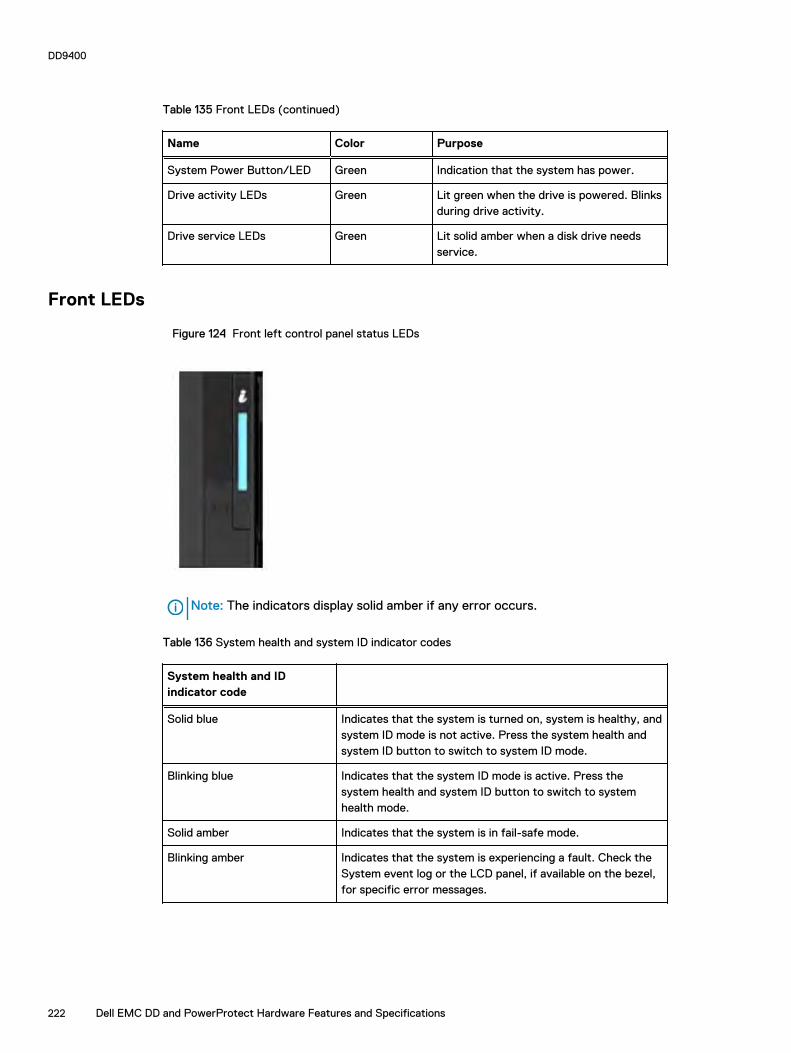
Table 135 Front LEDs (continued)
Name Color Purpose
System Power Button/LED Green Indication that the system has power.
Drive activity LEDs Green Lit green when the drive is powered. Blinksduring drive activity.
Drive service LEDs Green Lit solid amber when a disk drive needsservice.
Front LEDs
Figure 124 Front left control panel status LEDs
Note: The indicators display solid amber if any error occurs.
Table 136 System health and system ID indicator codes
System health and IDindicator code
Solid blue Indicates that the system is turned on, system is healthy, andsystem ID mode is not active. Press the system health andsystem ID button to switch to system ID mode.
Blinking blue Indicates that the system ID mode is active. Press thesystem health and system ID button to switch to systemhealth mode.
Solid amber Indicates that the system is in fail-safe mode.
Blinking amber Indicates that the system is experiencing a fault. Check theSystem event log or the LCD panel, if available on the bezel,for specific error messages.
DD9400
222 Dell EMC DD and PowerProtect Hardware Features and Specifications

Figure 125 Front right control panel power button LEDs
Table 137 Right control panel features
Item Indicator, button, orconnector
Description
1 Power button Indicates if the system is turned on or off. Press the powerbutton to manually turn on or off the system.
Note: Press the power button to gracefully shut downan ACPI-compliant operating system.
2 USB port (2) The USB ports are 4-pin, 2.0-compliant. These ports enableyou to connect USB devices to the system.
3 iDRAC Direct port The iDRAC Direct port is micro USB 2.0-compliant. This portenables you to access the iDRAC Direct features.
4 iDRAC Direct LED The iDRAC Direct LED indicator lights up to indicate that theiDRAC Direct port is connected.
5 VGA port Enables you to connect a display device to the system.
Table 138 iDRAC Direct LED indicator codes
iDRAC Direct LEDindicator code
Condition
Solid green for twoseconds
Indicates that the laptop or tablet is connected.
Flashing green (on for twoseconds and off for twoseconds)
Indicates that the laptop or tablet that is connected isrecognized.
Turns of Indicates that the laptop or tablet is unplugged.
DD9400
Dell EMC DD and PowerProtect Hardware Features and Specifications 223

Figure 126 Drive LEDs
The front contains 25 2.5" disk drive slots that can be populated with SSDs. Each SSD is housed ina drive carrier that contains two LEDs at the bottom of the carrier. The carrier's left blue LED is litwhenever an SSD is present in the slot, and it blinks when I/O activity is occurring on the disk. Theright amber LED is usually off and lights amber to indicate that the disk is faulted and must beserviced.
DD9400 SSD usage and configurations
DD9400 system uses a 16 x 2.5" drive slot mid-plane. In addition to the OS drives, it allows up to 12SSD drives for metadata cache implementation.
SSD configurations
The SSD slots on the front of the enclosure are shown below. The system come from the factorywith SSDs populated in the enclosure.
Figure 127 DD9400 SSD slot assignment
DD9400 supports 2.5% SSD option out of factory. Based on 3.84 TB SSD capacity, the requirednumber of SSDs for each DD9400 configuration is provided in the following table.
Table 139 DD9400 SSD configurations
Configuration Single node HA
3.84 TB SSDs in 2.5" bays 5 (internal) 3.84 TB 5 (internal) 3.84 TB
The cache SSDs are installed right to left starting from slot 7 down.
DD9400
224 Dell EMC DD and PowerProtect Hardware Features and Specifications
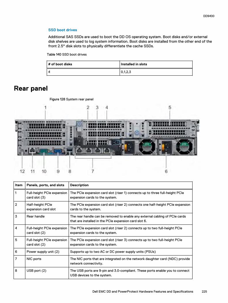
SSD boot drives
Additional SAS SSDs are used to boot the DD OS operating system. Boot disks and/or externaldisk shelves are used to log system information. Boot disks are installed from the other end of thefront 2.5" disk slots to physically differentiate the cache SSDs.
Table 140 SSD boot drives
# of boot disks Installed in slots
4 0,1,2,3
Rear panel
Figure 128 System rear panel
Item Panels, ports, and slots Description
1 Full-height PCIe expansioncard slot (3)
The PCIe expansion card slot (riser 1) connects up to three full-height PCIeexpansion cards to the system.
2 Half-height PCIeexpansion card slot
The PCIe expansion card slot (riser 2) connects one half-height PCIe expansioncards to the system.
3 Rear handle The rear handle can be removed to enable any external cabling of PCIe cardsthat are installed in the PCIe expansion card slot 6.
4 Full-height PCIe expansioncard slot (2)
The PCIe expansion card slot (riser 2) connects up to two full-height PCIeexpansion cards to the system.
5 Full-height PCIe expansioncard slot (2)
The PCIe expansion card slot (riser 3) connects up to two full-height PCIeexpansion cards to the system.
6 Power supply unit (2) Supports up to two AC or DC power supply units (PSUs)
7 NIC ports The NIC ports that are integrated on the network daughter card (NDC) providenetwork connectivity.
8 USB port (2) The USB ports are 9-pin and 3.0-compliant. These ports enable you to connectUSB devices to the system.
DD9400
Dell EMC DD and PowerProtect Hardware Features and Specifications 225

Item Panels, ports, and slots Description
9 VGA port Enables you to connect a display device to the system.
10 Serial port Enables you to connect a serial device to the system.
11 iDRAC9 dedicated port Enables you to remotely access iDRAC.
12 System identificationbutton
The System Identification (ID) button is available on the front and back of thesystems. Press the button to identify a system in a rack by turning on thesystem ID button. You can also use the system ID button to reset iDRAC and toaccess BIOS using the step through mode.
Rear LEDs
Figure 129 Onboard ID and iDRAC LEDs
1. iDRAC management port:
a. The green link LED on the left is lit whenever there is link at 1000BaseT and 100BaseTspeeds. The link LED is off when the link speed is 10BaseT or there is no link.
b. The green link LED on the right blinks whenever there is traffic on the port.
2. System identification LED: This blue LED can be turned on by software to visually identify thesystem.
PSU FRU LEDs
There are two power supplies, one in the upper left of the rear chassis and one on the bottomright. Each power supply has three LEDs: AC good, DC good, and Service. The top PSU is "right-side up" and the bottom PSU is "upside down."
Table 141 PSU FRU LEDs
Name Color Definition
AC Good Green AC input is as expected.
DC Good Green DC output is as expected.
Service Amber PSU has a fault condition anda must be replaced.
DD9400
226 Dell EMC DD and PowerProtect Hardware Features and Specifications
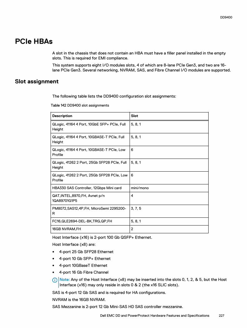
PCIe HBAs
A slot in the chassis that does not contain an HBA must have a filler panel installed in the emptyslots. This is required for EMI compliance.
This system supports eight I/O modules slots, 4 of which are 8-lane PCIe Gen3, and two are 16-lane PCIe Gen3. Several networking, NVRAM, SAS, and Fibre Channel I/O modules are supported.
Slot assignment
The following table lists the DD9400 configuration slot assignments:
Table 142 DD9400 slot assignments
Description Slot
QLogic, 41164 4 Port, 10GbE SFP+ PCIe, FullHeight
5, 8, 1
QLogic, 41164 4 Port, 10GBASE-T PCIe, FullHeight
5, 8, 1
QLogic, 41164 4 Port, 10GBASE-T PCIe, LowProfile
6
QLogic, 41262 2 Port, 25Gb SFP28 PCIe, FullHeight
5, 8, 1
QLogic, 41262 2 Port, 25Gb SFP28 PCIe, LowProfile
6
HBA330 SAS Controller, 12Gbps Mini card mini/mono
QAT,INTEL,8970,FH, Avnet p/n1QA89701G1P5
4
PM8072,SAS12,4P,FH, MicroSemi 2295200-R
3, 7, 5
FC16,QLE2694-DEL-BK,TRG,QP,FH 5, 8, 1
16GB NVRAM,FH 2
Host Interface (x16) is 2-port 100 Gb QSFP+ Ethernet.
Host Interface (x8) are:
l 4-port 25 Gb SFP28 Ethernet
l 4-port 10 Gb SFP+ Ethernet
l 4-port 10GBaseT Ethernet
l 4-port 16 Gb Fibre Channel
Note: Any of the Host Interface (x8) may be inserted into the slots 0, 1, 2, & 5, but the HostInterface (x16) may only reside in slots 0 & 2 (the x16 SLIC slots).
SAS is 4-port 12 Gb SAS and is required for HA configurations.
NVRAM is the 16GB NVRAM.
SAS Mezzanine is 2-port 12 Gb Mini-SAS HD SAS controller mezzanine.
DD9400
Dell EMC DD and PowerProtect Hardware Features and Specifications 227

Host Interface Mezzanine is either:
l 4-port 10GBaseSR SFP+ Ethernet mezzanine
l 4-port 10GBaseT RJ45 Ethernet mezzanine
I/O population rules
The following figures show the I/O module slot numbers.
The slot labeled N is the network daughter card, which contains ports ethMa, ethMb, ethMc, andethMd.
The physical interface name format for the other I/O module slots is ethXy, where X is the slotnumber and y is an alphanumeric character. For example, eth0a.
For most horizontal I/O module NIC interfaces, the port numbering goes from left to right, withethXa on the left. The horizontal I/O module slots on the left-in slots 1-3 are inverted. The portnumbering on these I/O modules in these slots goes from right to left, with ethXa on the right.
The management port ethMa is the first port set up by the Configuration Wizard. It is marked witha red rectangle in the figure below.
Figure 130 Slot numbering
The general population rules can be summarized as:
1. Populate a given I/O in the available slots listed.
2. Select the first available slot in the group.
3. Follow the steps for each I/O in the order specified.
4. Slots 0 and 2 should be reserved for x16 unless there are no available x8 slots.
Note: Installing HBAs requires opening the system and installing the HBA into the riser.
Riser# Slots (from top to bottom)
1 1, 2, 3
2 4, 5, 6, N
3 7, 8
Gen3 PCIe
Slots support Gen3 PCIe.
I/O module servicing
All I/O modules are user serviceable and may be replaced when the system is powered off. On-lineservice of I/O modules is not support. A module that is hot-inserted into the system will remainpowered off and will not be powered on until the next reboot of the system. A module that is hot-removed causes an operating system to immediately reboot.
DD9400
228 Dell EMC DD and PowerProtect Hardware Features and Specifications

DD9400 DIMM configurations
The SP Module contains two Intel SP processors each with an integrated memory controller thatsupports six channels of DDR4 memory. The CPU allows two DIMM slots per channel, so the SPModule supports 24 DIMM slots.
Each DDR4 DIMM is connected to the system board through an industry standard 288-pin DDR4DIMM connector. This system uses registered DIMMs with Dell EMC ControlCenter at 72 bits wide(64-bits data + 8-bits Dell EMC ControlCenter) up to a maximum of 2666MT/s speed.
Table 143 Memory configurations
Tier Total Memory Memory DIMMConfiguration
DD9400 Base 576 GB 12 x 32GB + 12 x 16GB
DD9400 Cloud Tier 576 GB 12 x 32GB + 12 x 16GB
Memory locations
To ensure maximum memory performance, there are memory DIMM population rules so that thememory loading and interleaving are optimal. The following table specifies the DIMM location rules.Each DIMM location contains contains a 16GB DIMM or a 32GB DIMM.
Table 144 DD9400 base DIMM configuration CPU 1
Total(GB)
Channel C Channel B Channel A Channel D Channel E Channel F
J0 J1 J2 J3 J4 J5 J6 J7 J8 J9 J10 J11
576 32GB 16GB 32GB 16GB 32GB 16GB 16GB 32GB 16GB 32GB 16GB 32GB
Table 145 DD9400 base DIMM configuration CPU 2
Total(GB)
Channel C Channel B Channel A Channel D Channel E Channel F
J12 J13 J14 J15 J16 J17 J18 J19 J20 J21 J22 J23
576 32GB 16GB 32GB 16GB 32GB 16GB 16GB 32GB 16GB 32GB 16GB 32GB
DD6900, DD9400, and DD9900 storage shelves configurationsand capacities
DD6900, DD9400, and DD9900 do not store data on internal disk drives and rely on external diskarray shelves to provide storage. DS60 disk shelves and ES40 shelves are connected to systemsusing 12 Gb Mini-SAS HD ports, which are implemented on the SAS HBAs.
The systems also support external metadata storage (cache) shelf FS25. External cache shelf onlyhosts DD OS depended metadata for performance acceleration.
The ES40 SAS shelf contains 15 drives, which includes 12 drives of usable storage, two paritydrives, and one hot spare.
DD9400
Dell EMC DD and PowerProtect Hardware Features and Specifications 229
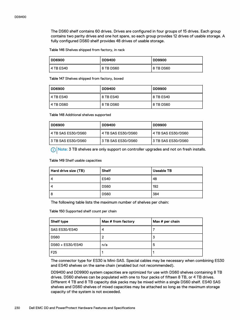
The DS60 shelf contains 60 drives. Drives are configured in four groups of 15 drives. Each groupcontains two parity drives and one hot spare, so each group provides 12 drives of usable storage. Afully configured DS60 shelf provides 48 drives of usable storage.
Table 146 Shelves shipped from factory, in rack
DD6900 DD9400 DD9900
4 TB ES40 8 TB DS60 8 TB DS60
Table 147 Shelves shipped from factory, boxed
DD6900 DD9400 DD9900
4 TB ES40 8 TB ES40 8 TB ES40
4 TB DS60 8 TB DS60 8 TB DS60
Table 148 Additional shelves supported
DD6900 DD9400 DD9900
4 TB SAS ES30/DS60 4 TB SAS ES30/DS60 4 TB SAS ES30/DS60
3 TB SAS ES30/DS60 3 TB SAS ES30/DS60 3 TB SAS ES30/DS60
Note: 3 TB shelves are only support on controller upgrades and not on fresh installs.
Table 149 Shelf usable capacities
Hard drive size (TB) Shelf Useable TB
4 ES40 48
4 DS60 192
8 DS60 384
The following table lists the maximum number of shelves per chain:
Table 150 Supported shelf count per chain
Shelf type Max # from factory Max # per chain
SAS ES30/ES40 4 7
DS60 2 3
DS60 + ES30/ES40 n/a 5
F25 1 1
The connector type for ES30 is Mini-SAS. Special cables may be necessary when combining ES30and ES40 shelves on the same chain (enabled but not recommended).
DD9400 and DD9900 system capacities are optimized for use with DS60 shelves containing 8 TBdrives. DS60 shelves can be populated with one to four packs of fifteen 8 TB, or 4 TB drives.Different 4 TB and 8 TB capacity disk packs may be mixed within a single DS60 shelf. ES40 SASshelves and DS60 shelves of mixed capacities may be attached so long as the maximum storagecapacity of the system is not exceeded.
DD9400
230 Dell EMC DD and PowerProtect Hardware Features and Specifications

CHAPTER 10
DD9500
This chapter contains the following topics:
l System features.................................................................................................................. 232l System specifications..........................................................................................................233l DD9500 storage capacity....................................................................................................234l Front panel.......................................................................................................................... 236l Rear panel........................................................................................................................... 240l I/O module slot assignments............................................................................................... 245l Internal System Components...............................................................................................247l DD9500 and ES30 shelf guidelines......................................................................................250l DD9500 and DS60 shelf guidelines......................................................................................252
Dell EMC DD and PowerProtect Hardware Features and Specifications 231
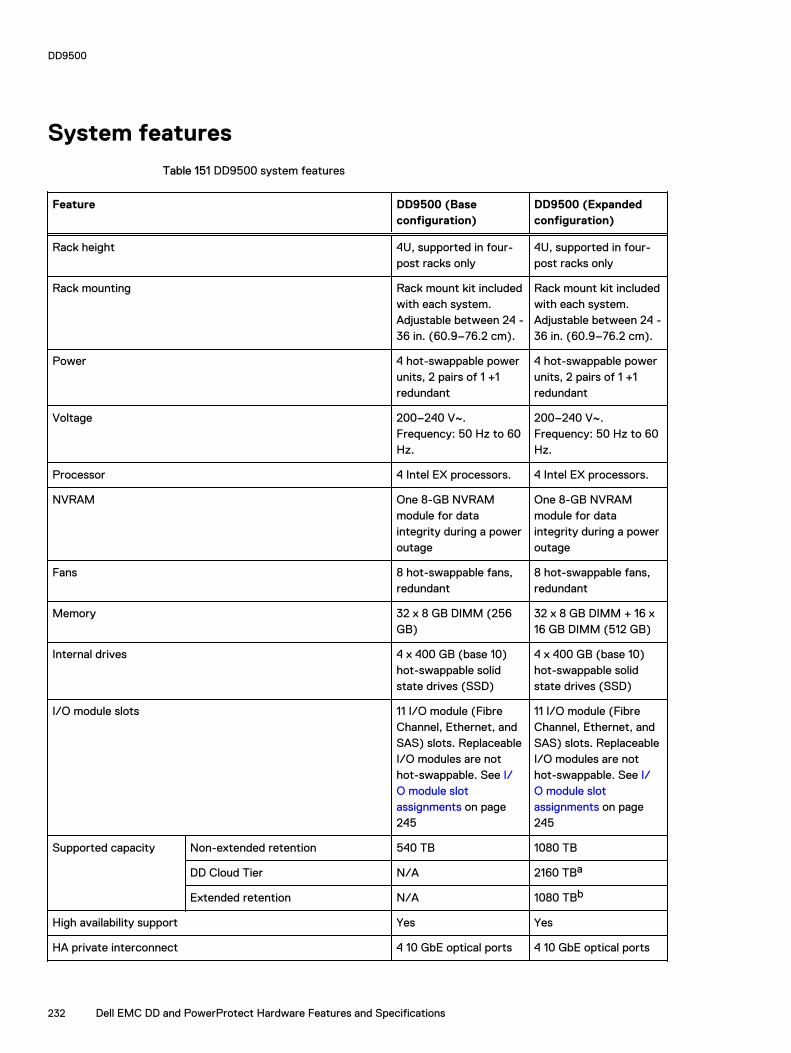
System features
Table 151 DD9500 system features
Feature DD9500 (Baseconfiguration)
DD9500 (Expandedconfiguration)
Rack height 4U, supported in four-post racks only
4U, supported in four-post racks only
Rack mounting Rack mount kit includedwith each system.Adjustable between 24 -36 in. (60.9–76.2 cm).
Rack mount kit includedwith each system.Adjustable between 24 -36 in. (60.9–76.2 cm).
Power 4 hot-swappable powerunits, 2 pairs of 1 +1redundant
4 hot-swappable powerunits, 2 pairs of 1 +1redundant
Voltage 200–240 V~.Frequency: 50 Hz to 60Hz.
200–240 V~.Frequency: 50 Hz to 60Hz.
Processor 4 Intel EX processors. 4 Intel EX processors.
NVRAM One 8-GB NVRAMmodule for dataintegrity during a poweroutage
One 8-GB NVRAMmodule for dataintegrity during a poweroutage
Fans 8 hot-swappable fans,redundant
8 hot-swappable fans,redundant
Memory 32 x 8 GB DIMM (256GB)
32 x 8 GB DIMM + 16 x16 GB DIMM (512 GB)
Internal drives 4 x 400 GB (base 10)hot-swappable solidstate drives (SSD)
4 x 400 GB (base 10)hot-swappable solidstate drives (SSD)
I/O module slots 11 I/O module (FibreChannel, Ethernet, andSAS) slots. ReplaceableI/O modules are nothot-swappable. See I/O module slotassignments on page245
11 I/O module (FibreChannel, Ethernet, andSAS) slots. ReplaceableI/O modules are nothot-swappable. See I/O module slotassignments on page245
Supported capacity Non-extended retention 540 TB 1080 TB
DD Cloud Tier N/A 2160 TBa
Extended retention N/A 1080 TBb
High availability support Yes Yes
HA private interconnect 4 10 GbE optical ports 4 10 GbE optical ports
DD9500
232 Dell EMC DD and PowerProtect Hardware Features and Specifications
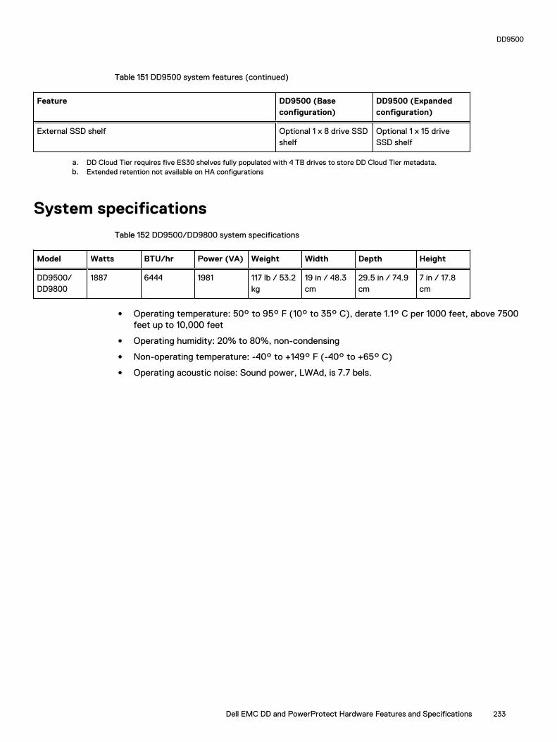
Table 151 DD9500 system features (continued)
Feature DD9500 (Baseconfiguration)
DD9500 (Expandedconfiguration)
External SSD shelf Optional 1 x 8 drive SSDshelf
Optional 1 x 15 driveSSD shelf
a. DD Cloud Tier requires five ES30 shelves fully populated with 4 TB drives to store DD Cloud Tier metadata.b. Extended retention not available on HA configurations
System specifications
Table 152 DD9500/DD9800 system specifications
Model Watts BTU/hr Power (VA) Weight Width Depth Height
DD9500/DD9800
1887 6444 1981 117 lb / 53.2kg
19 in / 48.3cm
29.5 in / 74.9cm
7 in / 17.8cm
l Operating temperature: 50° to 95° F (10° to 35° C), derate 1.1° C per 1000 feet, above 7500feet up to 10,000 feet
l Operating humidity: 20% to 80%, non-condensing
l Non-operating temperature: -40° to +149° F (-40° to +65° C)
l Operating acoustic noise: Sound power, LWAd, is 7.7 bels.
DD9500
Dell EMC DD and PowerProtect Hardware Features and Specifications 233

DD9500 storage capacityThe table lists the capacities of the systems. The internal indexes and other product componentsuse variable amounts of storage, depending on the type of data and the sizes of files. If you senddifferent datasets to otherwise identical systems, one system may, over time, have room for moreor less actual backup data than another.
Note: The system commands compute and display amounts of disk space or data as decimalmultiples of certain powers of two (210, 220, 230, and so forth). For example, 7 GiB of diskspace = 7 x 230 bytes = 7 x 1,073,741,824 bytes. The system sees this process as Base 2calculation.
Table 153 DD9500 storage capacity
System/InstalledMemory
Internal Disks Raw Storage(Base 10)
Data StorageSpace (Base 2Calculation)
Data StorageSpace (Base 10Calculation)
DD9500(3 SAS I/Omodules)
256 GB
2.5 in.; 4 x 400GB SATA SSDNo User Data
540 TB(external)
392.9 TiB 432 TB
DD9500(3 SAS I/Omodules)
512 GB
2.5 in.; 4 x 400GB SATA SSDNo User Data
1,080 TB(external)
786.8 TiB 864 TB
DD9500 with DDCloud Tiersoftware(4 SAS I/Omodules)
512 GB
2.5 in.; 4 x 400GB SATA SSDNo User Data
3,240 TB(external)
2360.4 TiB 2592 TB
DD9500 withExtendedRetention (ER)software(4 SAS I/Omodules)
512 GB
2.5 in.; 4 x 400GB SATA SSDNo User Data
2,160 TB(external)
1573.6 TiB 1728 TB
Table 154 DD9500 with ES30 SAS shelves
DD9500 DD9500
Memory (GB) 256 512
SAS I/O modules x ports permodule
3x4 3x4
ES30 support (TB) SAS 30, 45, 60 SAS 30, 45, 60
Maximum shelves per set 5 5
DD9500
234 Dell EMC DD and PowerProtect Hardware Features and Specifications
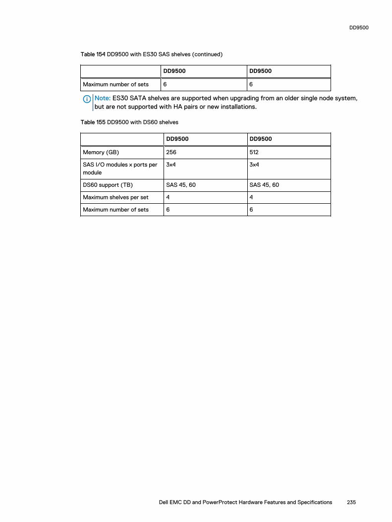
Table 154 DD9500 with ES30 SAS shelves (continued)
DD9500 DD9500
Maximum number of sets 6 6
Note: ES30 SATA shelves are supported when upgrading from an older single node system,but are not supported with HA pairs or new installations.
Table 155 DD9500 with DS60 shelves
DD9500 DD9500
Memory (GB) 256 512
SAS I/O modules x ports permodule
3x4 3x4
DS60 support (TB) SAS 45, 60 SAS 45, 60
Maximum shelves per set 4 4
Maximum number of sets 6 6
DD9500
Dell EMC DD and PowerProtect Hardware Features and Specifications 235

Front panelThe four solid state drives (SSDs), the storage processor (SP), and the fans are accessed fromthe front of the system. The SP must be pulled out to provide access to the DIMMs. The fans areaccessed without pulling or removing the SP and they are hot-swappable. The photo shows theinterfaces on the front of the system.
Figure 131 Front panel components
1. SSD slot 02. SSD slot 13. SSD slot 24. SSD slot 35. Front LEDs6. USB ports7. Power button8. Fan tray thumbscrew (left)9. SP module thumbscrew to secure the ejector handle10. Fan tray thumbscrew (right)
Front LED indicatorsOn the front panel to the right of SSD #4 (in Slot 3) are 3 LEDs that show high level systemstatus. The System Power LED glows blue to show the system is powered on.
Note: The system can have power (be plugged in) but the blue LEDs are off if the system ispowered off.
The SP Service LED is normally off, but glows amber whenever the storage processor (SP)requires service. The Enclosure Service LED is normally off, but glows amber whenever the SP orother replaceable parts require service. The System Power and Enclosure Service LEDs are visiblethrough the front bezel.
DD9500
236 Dell EMC DD and PowerProtect Hardware Features and Specifications

Figure 132 Service LEDs
1. SP service LED — Amber light indicates that the SP or one of its components needs service.2. Enclosure Service LED — This is normally off, but amber light indicates that the enclosure orsomething within the enclosure— the fans, SP, I/O modules, management module etc—requires service.3. System power LED — Blue light indicates system running
DD9500
Dell EMC DD and PowerProtect Hardware Features and Specifications 237

The power button shown in the picture is used when a system needs to be powered up after a shutdown using the system poweroff command. Once power is restored the system power LEDlight turns blue.
Figure 133 Power button
1. System power LED — Blue light indicates system running2. Power button
The LEDs in the front are shown in the following figure.
Figure 134 Front LEDs
1. SSD LED in slot 02. SSD LED in slot 13. SSD LED in slot 24. SSD LED in slot 35. System power LED — Blue light indicates system running
DD9500
238 Dell EMC DD and PowerProtect Hardware Features and Specifications

Table 156 Front panel LED status indicators
Part Description or Location State
System, SP fault Exclamation point within atriangle
Dark indicates normaloperation. Amber indicatesfailure.
System, chassis fault Exclamation point within atriangle
Dark indicates normaloperation. Amber indicates afault condition.
SSD Top LED Solid blue, disk ready, blinkswhile busy.
SSD Bottom LED Dark indicates healthy. Solidamber indicates disk fail.
Solid-state drivesA system contains 4 hot-swappable 2.5 in. 400 GB solid-state drives (SSD) located in the front.There are four drive bays numbered 0–3 from left to right. A dual drive failure allows the system tooperate without disruption.
Each drive has a blue colored power LED and an amber fault LED.
Figure 135 SSD drives
1. Slot 02. Slot 13. Slot 24. Slot 3
DD9500
Dell EMC DD and PowerProtect Hardware Features and Specifications 239

Rear panelIn the rear of the system, the top section contains the 4 power supply units. In the middle of thesection, on the left, is serial number tag location. To the right of the serial number tag location isthe management module. The lower section contains the NVRAM and the I/O modules numbered 0through 11 from left to right. The photo shows the hardware features and interfaces on the rear ofthe system.
Figure 136 Features on rear of chassis
1. Power supply units2. Serial number tag3. Management module4. NVRAM and I/O modules (slots 0-11)
The figure shows the location of the serial number tag on the left of the management module.
Figure 137 Serial number tag location
DD9500
240 Dell EMC DD and PowerProtect Hardware Features and Specifications

Power supply unitsA DD9500/DD9800 system has four power supply units, numbered PSU0, PSU1, PSU2, and PSU3from left to right. Each power supply has its own integral cooling fan.
Note: The DD9500/DD9800 system should be powered from redundant AC sources. Thisallows one AC source to fail or be serviced without impacting system operation. PSU0 andPSU1 should be attached to one AC source. PSU2 and PSU3 should be attached to the otherAC source.
The AC power plugs are located to the right of each power supply. The wire clips for the AC cordshold the cords in place. The wire clips must be disengaged before disconnecting the AC power toeach power supply.
Figure 138 Four power supplies
Management moduleThe following figure shows the location of the management module on the rear of the system andidentifies the interfaces.
Figure 139 Management module
1. Left blue thumbscrew to loosen the management module2. 4 x 1000BaseT Ethernet ports (For details, see the picture - 1000BaseT Ethernet ports)
DD9500
Dell EMC DD and PowerProtect Hardware Features and Specifications 241

3. Service network port (IPMI, 1000BaseT Ethernet port)4. Service LED5. VGA port6. Serial port7. Four USB ports8. Right blue thumbscrew to loosen the management module
Figure 140 1000BaseT Ethernet ports
- Lower left port: physical #0, logical ethMa- Top left port: physical #1, logical ethMb- Lower right port: physical #2, logical ethMc- Top right port: physical #3, logical ethMd
Rear LED indicators
The rear elements containing LEDs include each power supply, each I/O module, and themanagement module.
The figure shows the rear LEDS.
Figure 141 Rear LEDs
1. Management module service LEDs2. Power supply LEDs
DD9500
242 Dell EMC DD and PowerProtect Hardware Features and Specifications

3. NVRAM LEDs4. I/O Module LEDs
The power supply LEDs include:
l AC LED on top
l DC LED in the middle
l Service Required LED on the bottom
Figure 142 Power supply LEDs
Table 157 Rear LED status indicators
Part Description or Location State
Power supply AC LED Steady green indicates normalAC input power.
Power supply DC LED Steady green indicates normalDC output power.
Power supply Service LED Solid amber indicates a failedpower supply.
I/O module I/O module handle Solid green means I/O modulefunctioning normally. Amberindicates a fault condition.Each I/O module also has perport LEDs. These LEDs areblue on the FC, and SAS I/Omodules. They light when theport is active.
Management module Bicolor LED Solid green meansmanagement modulefunctioning normally. Amberindicates that themanagement module requiresservice.
Available I/O modulesI/O modules may include:
DD9500
Dell EMC DD and PowerProtect Hardware Features and Specifications 243

l Quad port Ethernet 10GBase-SR Optical with LC connectors
l Quad port Ethernet 10GBase-CX1 Direct Attach Copper with SPF+ module
l Quad port Ethernet 10GBase-T Copper
l Dual port 16 Gbps Fibre Channel
l Quad port 6 Gbps SAS
I/O module port physical mapping
I/O module ports are numbered starting with 0. When the I/O modules are inserted vertically intothe system chassis, port 0 is on the bottom.
I/O module port logical mapping
The numerical port labels on the I/O modules are identified logically in the DD OS software by thefollowing descriptions:
l I/O module type
l I/O module slot
l Alphabetic character corresponding to the physical port number
The following example is based on a four-port Ethernet I/O module installed in slot 1 of the systemchassis.
Table 158 Physical to logical port mapping example
Physical port Logical identifier
0 eth1a
1 eth1b
2 eth1c
3 eth1d
Ethernet I/O module optionsThe available Ethernet I/O modules are:
l Dual Port 10GBase-SR Optical with LC connectors
l Dual Port 10GBase-CX1 Direct Attach Copper with SPF+ module
l Quad Port 1000Base-T Copper with RJ-45 connectors
l Quad port 2 port 1000Base-T Copper (RJ45) /2 port 1000Base-SR Optical
Fibre Channel I/O modulesA Fibre Channel (FC) I/O module is a dual-port Fibre Channel module. Up to four FC I/O modulesmay be installed. The optional virtual tape library (VTL) feature requires at least one FC I/Omodule. Boost over Fibre Channel is an optional feature and requires at least one FC I/O module. Amaximum of four FC I/O modules may be installed in a system using either VTL or the Boostprotocol or a combination of both protocols.
DD9500
244 Dell EMC DD and PowerProtect Hardware Features and Specifications

SAS I/O modulesDD9500 systems have three quad-port SAS I/O modules installed in slots 2, 3 and 6. Systemsconfigured with DD Extended Retention (ER) or DD Cloud Tier software options require anadditional SAS I/O module in slot 9.
I/O module slot assignmentsThe following figure shows the location of the NVRAM and I/O modules.
Figure 143 Location of NVRAM and I/O modules
1. NVRAM module—slot 02. I/O modules—slots 1 to 11 (See the I/O module slot assignments table.)
The table shows the I/O module slot assignments for the DD9500 system. Each type of I/Omodule is restricted to certain slots.
Table 159 DD9500 I/O module slot assignments
Slot Baseconfiguration
HA ER or DD Cloud Tier DD Cloud Tier and HA
0 NVRAM NVRAM NVRAM NVRAM
1 Fibre Channel(FC), Ethernet orempty
Fibre Channel (FC),Ethernet or empty
Fibre Channel (FC),Ethernet or empty
Fibre Channel (FC),Ethernet or empty
2 SAS SAS SAS SAS
3 SAS SAS SAS SAS
4 FC, Ethernet orempty
FC, Ethernet orempty
FC, Ethernet or empty FC, Ethernet or empty
5 FC, Ethernet orempty
FC, Ethernet orempty
FC, Ethernet or empty FC, Ethernet or empty
6 SAS SAS SAS SAS
DD9500
Dell EMC DD and PowerProtect Hardware Features and Specifications 245

Table 159 DD9500 I/O module slot assignments (continued)
Slot Baseconfiguration
HA ER or DD Cloud Tier DD Cloud Tier and HA
7 FC, Ethernet orempty
FC, Ethernet orempty
FC, Ethernet or empty FC, Ethernet or empty
8 FC, Ethernet orempty
FC, Ethernet orempty
FC, Ethernet or empty FC, Ethernet or empty
9 Not available(contains a filler)
Not available(contains a filler)
SAS SAS
10 FC, Ethernet orempty
FC, Ethernet orempty
FC, Ethernet or empty FC, Ethernet or empty
11 FC, Ethernet orempty
10 Gb opticalEthernet forinterconnectbetween the primaryand standby nodes inthe HA pair.
FC, Ethernet or empty 10 Gb optical Ethernetfor interconnect betweenthe primary and standbynodes in the HA pair.
Slot addition rulesThis system has 12 slots for I/O modules. Slots 0, 2, 3, 6, 9, and 11 are reserved for mandatory I/Omodules. Slots 1, 4, 5, 7, 8, and 10 support optional host interface I/O modules. The maximumsupported number of any type of host interface (Ethernet or FC) I/O module is four.
Note: The maximum number of host interface I/O modules that are listed above does notinclude the 10 GbE Optical I/O module for the HA interconnect. The HA interconnect is a fifthEthernet module, but it is reserved for communication between the two nodes of an HA pair,and is not available for host connections.
The maximum number of I/O modules, including both mandatory and optional I/O modules,supported in a system varies by configuration:
l Single node: 10
l HA: 10
l DD Extended Retention: 10
l DD Cloud Tier: 10
l HA + DD Cloud Tier: 11
Three I/O module slots are tied to each CPU in the system. When installing I/O modules, balancethe load across the CPUs. The following table shows the CPU to slot mappings.
CPU I/O module slots
0 0, 1, 2
1 3, 4, 5
2 6, 7, 8
3 9, 10, 11
The following table assigns rules for populating the I/O modules.
DD9500
246 Dell EMC DD and PowerProtect Hardware Features and Specifications

Table 160 I/O module slot population rules
Step I/O module type Slots Notes
1: Populate mandatoryI/O modules
NVRAM 0
Quad Port SAS 2
Quad Port SAS 3
Quad Port SAS 6
Quad Port SAS 9 This slot remainsempty if the systemdoes not use DDCloud Tier or DDExtended Retention.
Quad Port 10GbEOptical
11 This slot remainsempty if the systemdoes not use HA.
2: Populate hostinterface I/O modules
l Quad Port 10GbESR
l Quad Port 10GBase-T
l Dual Port 16 GbpsFibre Channel
1, 4, 5, 7, 8, 10 Install host interfaceI/O modules in theremaining slots. Installthe I/O modules tobalance the loadacross the CPUs. Donot place twoEthernet or two FCI/O modules on oneCPU.a
a. HA systems are the exception to this guidance, as a Quad Port 10GbE SR I or Quad Port 10GBase-T /O module can be added in slot 10 alongside the HA interconnect I/O module inslot 11.
Internal System ComponentsThe storage processor (SP) is a subassembly within the chassis that contains the memory riserswith the DIMMs and a fan tray with fan modules. The SP module also contains the 4 CPUs, whichcannot be removed or replaced.
l The memory risers tray, which contains 8 memory risers with DIMMs, can be accessed fromthe front of the SP module. The memory risers are not hot swappable
l The fan tray, which contains 8 fan modules, can be accessed from the front of the SP module.The fans are hot swappable.
The DIMMS can be accessed by pulling the entire SP module away from the chassis. Depending onthe model, there are DIMMs totaling:
l 256 GB or 512 GB for a DD9500 system.
l 256 GB or 768 GB for a DD9800 system.
The figures show the location of the SP module, the DIMM risers accessed from a partly removedSP module, and the fan tray partly removed.
Do not lift the DD9500/DD9800 system, or the storage processor (SP) module, or any modules bythe handle. The handle is not designed to support the weight of the populated shelf. Also do not
DD9500
Dell EMC DD and PowerProtect Hardware Features and Specifications 247

carry the DD9500/DD9800 system or the SP by the handle. The handles are only intended to beused to insert or remove the SP module.
Figure 144 SP module
Figure 145 Releasing a memory riser
1. Left riser card ejector handle2. Release button
DD9500
248 Dell EMC DD and PowerProtect Hardware Features and Specifications

3. Right riser card ejector handle
Figure 146 Open fan tray
Note: Do not loosen the blue thumbscrew on the SP latch handle to access the fan tray. Usethe orange thumbscrews on the front as shown in the picture.
1. Left fan tray thumbscrew2. Front panel left handle3. Front panel right handle4. Right fan tray thumbscrew5. Location map of the fans
DIMM modulesThe DD9500 system contains the following memory configurations:
Table 161 DD9500 memory configurations
System Base Expanded ER/DD Cloud Tier
DD9500 32 x 8 GB DIMMs(256 GB)
32 x 8 GB DIMMs + 16x 16 GB DIMMs (512GB)
32 x 8 GB DIMMs + 16x 16 GB DIMMs (512GB)
Cooling fansA system contains eight hot-swappable cooling fans in a 7+1 redundant configuration, which islocated in the front of the system within a movable fan tray. The fans provide cooling for theprocessors, DIMMs, and I/O modules. Each fan has an LED which glows amber when the fan isfailed or faulted. A system can run with one fan faulted.
DD9500
Dell EMC DD and PowerProtect Hardware Features and Specifications 249

DD9500 and ES30 shelf guidelines
The system rediscovers newly configured shelves after it restarts. You can power off the systemand recable shelves to any other position in a set, or to another set. To take advantage of thisflexibility, you need to follow these rules before making any cabling changes:
l Do not exceed the maximum shelf configuration values for your system as listed in thefollowing table below.
l Use the Installation and Setup Guide for your system to minimize the chance of a cablingmistake.
l A system cannot exceed its maximum raw external shelf capacity, regardless of added shelfcapacity.
l DD9500 systems support ES30 SATA shelves after controller upgrades from older models.
l ES30 SATA shelves must be on their own chain.
Table 162 DD9500 and ES30 shelf configuration
DD system Memoryrequired(GB)
SAS cards/port percard
ES30support(TB)
Maxshelvesper set
Maxnumber ofsets
Max externalcapacityavailable (TB)1
Max RAWexternalcapacity(TB) 2
DD9500 256 3x4 SAS 30,45, 60;SATA 15,30, 45
53 6 432 540
DD9500 512 3x4 SAS 30,45, 60;SATA 15,30, 45
53 6 864 1080
DD9500 ER 4, 5 512 4x4 SAS 30,45, 60;SATA 15,30, 45
7 8 1728 2160
DD9500 HA6, 7 256 3x4 SAS 30,45, 60
53 6 432 540
DD9500 HA6, 7 512 3x4 SAS 30,45, 60
53 6 864 1080
DD9500 w/Cloud Tier
512 4x4 SAS 30,45, 60;SATA 15,30, 45
7 8 864 (max),additional 240SAS dedicatedto Cloud Tier
1080 (max),additional 300SASdedicated toCloud Tier
DD9500 w/ HAand Cloud Tier
512 4x4 SAS 30,45, 60
7 8 864 (max),additional 240SAS dedicatedto Cloud Tier
1080 (max),additional 300SASdedicated toCloud Tier
1. This figure only counts drives that have user data in the shelves.
DD9500
250 Dell EMC DD and PowerProtect Hardware Features and Specifications

2. The raw capacity of an ES30 is 125% of the available capacity.
4. 5 shelves maximum with ES30, 4 is the recommended maximum. 4 shelves maximum with ES20, 3 is the recommended
maximum.
5. The maximum shelf count for any specific drive/shelf size might be less than the product of max shelves x max shelves per set.
6. There is no support for ERSO on HA systems.
7. There is no support for HA with SATA drives.
Types of cabinets and power connectionsThe ES30 chassis is installed in two types of racks: 40U-C (existing racks) and the 40U-P (newerracks). The racks use one phase or 3-phase power connections.
3-Phase power connections for 40U-P (current racks)
Some environments use 3-phase power for 40U-P racks that are used for several systems. Inthose situations, it is desirable to balance the current draw across all three phases. Therecommended 3-phase power cabling attempts to do that, but an optimal configuration dependson the specific installation.
Cabling shelves
Note:
l Before cabling the shelves, physically install all shelves in the racks. Refer to the rail kitinstallation instructions included with the ES30 shelf for rack mounting.
l The documentation refers to two SAS HBAs. If only one HBA is allowed in a system, thenuse another port as defined later for that specific system.
l On an HA system, add cables from the second node to open ports at the end of the sets.The ports on the second node must connect to the same sets as the corresponding portson the first node.
Ports on the system’s SAS HBA cards connect directly to a shelf controller’s host port. Forredundancy, you need to create dual paths by using a port on one SAS HBA card to connect to oneshelf controller in each shelf set, and a port on another SAS HBA card to connect to another shelfcontroller in the same shelf set. With dual paths, if one SAS HBA card fails, the shelf is stilloperational. However, in the unlikely event any single shelf becomes completely disconnected frompower or SAS cables and becomes disconnected from a previously operational shelf, the filesystem goes down and the shelf is not operational. This is considered a double failure.
There are two kinds of configurations: one shelf in a set or multiple shelves in a set.
DD9500 and cabling
Note: If a system installation does not follow ALL of these rules, it is not a legitimateconfiguration.
Prerequisites:
l Follow the minimum and maximum shelf capacity configuration provided in the table.
l You cannot have ES30 SATA and ES30 SAS shelves in the same set.
l You cannot exceed the maximum amount of raw capacity displayed in the product's cablingtable.
l You cannot exceed the maximum number of shelves displayed in the product's cabling table.
l You cannot have more than five ES30s in a single set (maximum of four is preferred).
DD9500
Dell EMC DD and PowerProtect Hardware Features and Specifications 251
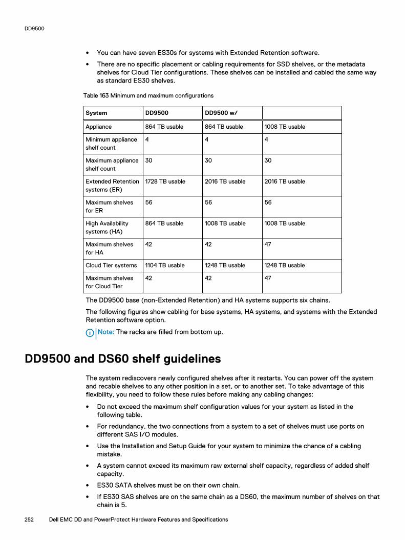
l You can have seven ES30s for systems with Extended Retention software.
l There are no specific placement or cabling requirements for SSD shelves, or the metadatashelves for Cloud Tier configurations. These shelves can be installed and cabled the same wayas standard ES30 shelves.
Table 163 Minimum and maximum configurations
System DD9500 DD9500 w/
Appliance 864 TB usable 864 TB usable 1008 TB usable
Minimum applianceshelf count
4 4 4
Maximum applianceshelf count
30 30 30
Extended Retentionsystems (ER)
1728 TB usable 2016 TB usable 2016 TB usable
Maximum shelvesfor ER
56 56 56
High Availabilitysystems (HA)
864 TB usable 1008 TB usable 1008 TB usable
Maximum shelvesfor HA
42 42 47
Cloud Tier systems 1104 TB usable 1248 TB usable 1248 TB usable
Maximum shelvesfor Cloud Tier
42 42 47
The DD9500 base (non-Extended Retention) and HA systems supports six chains.
The following figures show cabling for base systems, HA systems, and systems with the ExtendedRetention software option.
Note: The racks are filled from bottom up.
DD9500 and DS60 shelf guidelines
The system rediscovers newly configured shelves after it restarts. You can power off the systemand recable shelves to any other position in a set, or to another set. To take advantage of thisflexibility, you need to follow these rules before making any cabling changes:
l Do not exceed the maximum shelf configuration values for your system as listed in thefollowing table.
l For redundancy, the two connections from a system to a set of shelves must use ports ondifferent SAS I/O modules.
l Use the Installation and Setup Guide for your system to minimize the chance of a cablingmistake.
l A system cannot exceed its maximum raw external shelf capacity, regardless of added shelfcapacity.
l ES30 SATA shelves must be on their own chain.
l If ES30 SAS shelves are on the same chain as a DS60, the maximum number of shelves on thatchain is 5.
DD9500
252 Dell EMC DD and PowerProtect Hardware Features and Specifications
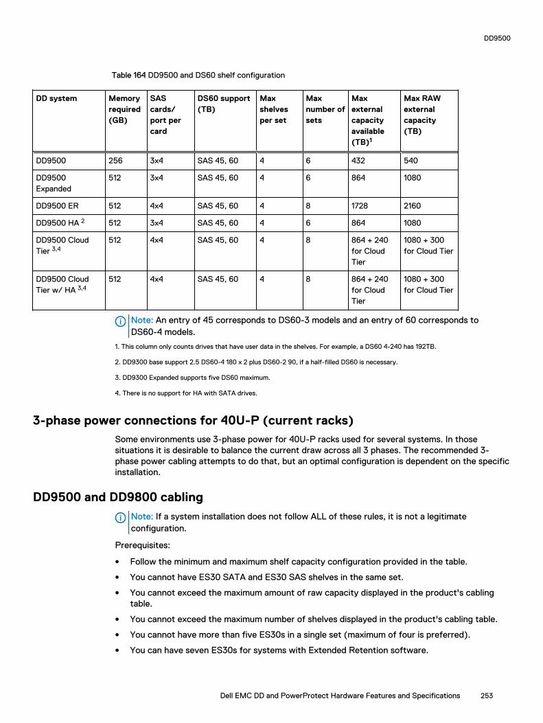
Table 164 DD9500 and DS60 shelf configuration
DD system Memoryrequired(GB)
SAScards/port percard
DS60 support(TB)
Maxshelvesper set
Maxnumber ofsets
Maxexternalcapacityavailable(TB)1
Max RAWexternalcapacity(TB)
DD9500 256 3x4 SAS 45, 60 4 6 432 540
DD9500Expanded
512 3x4 SAS 45, 60 4 6 864 1080
DD9500 ER 512 4x4 SAS 45, 60 4 8 1728 2160
DD9500 HA 2 512 3x4 SAS 45, 60 4 6 864 1080
DD9500 CloudTier 3,4
512 4x4 SAS 45, 60 4 8 864 + 240for CloudTier
1080 + 300for Cloud Tier
DD9500 CloudTier w/ HA 3,4
512 4x4 SAS 45, 60 4 8 864 + 240for CloudTier
1080 + 300for Cloud Tier
Note: An entry of 45 corresponds to DS60-3 models and an entry of 60 corresponds toDS60-4 models.
1. This column only counts drives that have user data in the shelves. For example, a DS60 4-240 has 192TB.
2. DD9300 base support 2.5 DS60-4 180 x 2 plus DS60-2 90, if a half-filled DS60 is necessary.
3. DD9300 Expanded supports five DS60 maximum.
4. There is no support for HA with SATA drives.
3-phase power connections for 40U-P (current racks)Some environments use 3-phase power for 40U-P racks used for several systems. In thosesituations it is desirable to balance the current draw across all 3 phases. The recommended 3-phase power cabling attempts to do that, but an optimal configuration is dependent on the specificinstallation.
DD9500 and DD9800 cabling
Note: If a system installation does not follow ALL of these rules, it is not a legitimateconfiguration.
Prerequisites:
l Follow the minimum and maximum shelf capacity configuration provided in the table.
l You cannot have ES30 SATA and ES30 SAS shelves in the same set.
l You cannot exceed the maximum amount of raw capacity displayed in the product's cablingtable.
l You cannot exceed the maximum number of shelves displayed in the product's cabling table.
l You cannot have more than five ES30s in a single set (maximum of four is preferred).
l You can have seven ES30s for systems with Extended Retention software.
DD9500
Dell EMC DD and PowerProtect Hardware Features and Specifications 253

l There are no specific placement or cabling requirements for SSD shelves, or the metadatashelves for Cloud Tier configurations. These shelves can be installed and cabled the same wayas standard ES30 shelves.
Table 165 Minimum and maximum configurations
System DD9500 DD9500 w/
Appliance 864 TB usable 864 TB usable 1008 TB usable
Minimum applianceshelf count
4 4 4
Maximum applianceshelf count
30 30 30
Extended Retentionsystems (ER)
1728 TB usable 2016 TB usable 2016 TB usable
Maximum shelvesfor ER
56 56 56
High Availabilitysystems (HA)
864 TB usable 1008 TB usable 1008 TB usable
Maximum shelvesfor HA
42 42 47
Cloud Tier systems 1104 TB usable 1248 TB usable 1248 TB usable
Maximum shelvesfor Cloud Tier
42 42 47
The DD9500 base (non-Extended Retention) and HA systems supports six chains.
The following figures show cabling for base systems, HA systems, and systems with the ExtendedRetention software option.
Note: The racks are filled from bottom up.
DD9500
254 Dell EMC DD and PowerProtect Hardware Features and Specifications

CHAPTER 11
DD9800
This chapter contains the following topics:
l DD9800 system features.....................................................................................................256l DD9800 system specifications............................................................................................ 257l DD9800 storage capacity....................................................................................................258l DD9800 front panel.............................................................................................................260l Rear panel........................................................................................................................... 264l I/O module slot assignments............................................................................................... 269l Internal system components................................................................................................ 271l DD9800 and ES30 shelf guidelines...................................................................................... 273l DD9800 and DS60 shelf guidelines......................................................................................276
Dell EMC DD and PowerProtect Hardware Features and Specifications 255

DD9800 system features
Table 166 DD9800 system features
Feature DD9800 (Baseconfiguration)
DD9800 (Expandedconfiguration)
Rack height 4U, supported in four-post racks only
4U, supported in four-post racks only
Rack mounting Rack mount kit includedwith each system.Adjustable between 24 -36 in. (60.9–76.2 cm).
Rack mount kit includedwith each system.Adjustable between 24 -36 in. (60.9–76.2 cm).
Power 4 hot-swappable powerunits, 2 pairs of 1 +1redundant
4 hot-swappable powerunits, 2 pairs of 1 +1redundant
Voltage 200–240 V~.Frequency: 50 Hz to 60Hz.
200–240 V~.Frequency: 50 Hz to 60Hz.
Processor 4 Intel EX processors. 4 Intel EX processors.
NVRAM One 8-GB NVRAMmodule for dataintegrity during a poweroutage
One 8-GB NVRAMmodule for dataintegrity during a poweroutage
Fans 8 hot-swappable fans,redundant
8 hot-swappable fans,redundant
Memory 32 x 8 GB DIMM (256GB)
32 x 8 GB DIMM + 32 x16 GB DIMM (768 GB)
Internal drives 4 x 400 GB (base 10)hot-swappable solidstate drives (SSD)
4 x 400 GB (base 10)hot-swappable solidstate drives (SSD)
I/O module slots 11 I/O module (FibreChannel, Ethernet, andSAS) slots. ReplaceableI/O modules are nothot-swappable. See I/O module slotassignments on page269
11 I/O module (FibreChannel, Ethernet, andSAS) slots. ReplaceableI/O modules are nothot-swappable. See I/O module slotassignments on page269
Supported capacity Non-extended retention 630 TB 1260 TB
DD Cloud Tier N/A 2520 TB a
Extended retention N/A 1260 TB b
High availability support Yes Yes
HA private interconnect 4 10 GbE optical ports 4 10 GbE optical ports
External SSD shelf 1 x 8 drive SSD shelf 1 x 15 drive SSD shelf
DD9800
256 Dell EMC DD and PowerProtect Hardware Features and Specifications

Table 166 DD9800 system features (continued)
a. DD Cloud Tier requires five ES30 shelves fully populated with 4 TB drives to store DD Cloud Tier metadata.b. Extended retention not available on HA configurations
DD9800 system specifications
Table 167 DD9800 system specifications
Model Watts BTU/hr Power (VA) Weight Width Depth Height
DD9800 1887 6444 1981 117 lb / 53.2kg
19 in / 48.3cm
29.5 in / 74.9cm
7 in / 17.8cm
l Operating temperature: 50° to 95° F (10° to 35° C), derate 1.1° C per 1000 feet, above 7500feet up to 10,000 feet
l Operating humidity: 20% to 80%, non-condensing
l Non-operating temperature: -40° to +149° F (-40° to +65° C)
l Operating acoustic noise: Sound power, LWAd, is 7.7 bels.
DD9800
Dell EMC DD and PowerProtect Hardware Features and Specifications 257
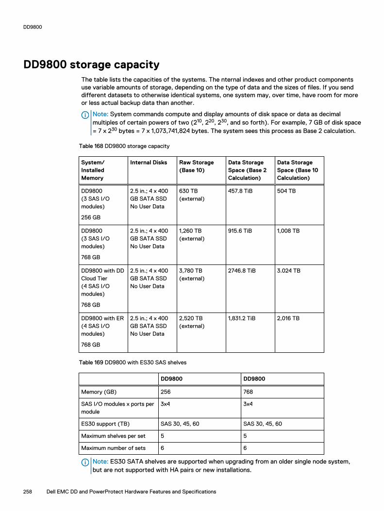
DD9800 storage capacityThe table lists the capacities of the systems. The nternal indexes and other product componentsuse variable amounts of storage, depending on the type of data and the sizes of files. If you senddifferent datasets to otherwise identical systems, one system may, over time, have room for moreor less actual backup data than another.
Note: System commands compute and display amounts of disk space or data as decimalmultiples of certain powers of two (210, 220, 230, and so forth). For example, 7 GB of disk space= 7 x 230 bytes = 7 x 1,073,741,824 bytes. The system sees this process as Base 2 calculation.
Table 168 DD9800 storage capacity
System/InstalledMemory
Internal Disks Raw Storage(Base 10)
Data StorageSpace (Base 2Calculation)
Data StorageSpace (Base 10Calculation)
DD9800(3 SAS I/Omodules)
256 GB
2.5 in.; 4 x 400GB SATA SSDNo User Data
630 TB(external)
457.8 TiB 504 TB
DD9800(3 SAS I/Omodules)
768 GB
2.5 in.; 4 x 400GB SATA SSDNo User Data
1,260 TB(external)
915.6 TiB 1,008 TB
DD9800 with DDCloud Tier(4 SAS I/Omodules)
768 GB
2.5 in.; 4 x 400GB SATA SSDNo User Data
3,780 TB(external)
2746.8 TiB 3.024 TB
DD9800 with ER(4 SAS I/Omodules)
768 GB
2.5 in.; 4 x 400GB SATA SSDNo User Data
2,520 TB(external)
1,831.2 TiB 2,016 TB
Table 169 DD9800 with ES30 SAS shelves
DD9800 DD9800
Memory (GB) 256 768
SAS I/O modules x ports permodule
3x4 3x4
ES30 support (TB) SAS 30, 45, 60 SAS 30, 45, 60
Maximum shelves per set 5 5
Maximum number of sets 6 6
Note: ES30 SATA shelves are supported when upgrading from an older single node system,but are not supported with HA pairs or new installations.
DD9800
258 Dell EMC DD and PowerProtect Hardware Features and Specifications

Table 170 DD9800 with DS60 shelves
DD9800 DD9800
Memory (GB) 256 768
SAS I/O modules x ports permodule
3x4 3x4
DS60 support (TB) SAS 45, 60 SAS 45, 60
Maximum shelves per set 4 4
Maximum number of sets 6 6
DD9800
Dell EMC DD and PowerProtect Hardware Features and Specifications 259
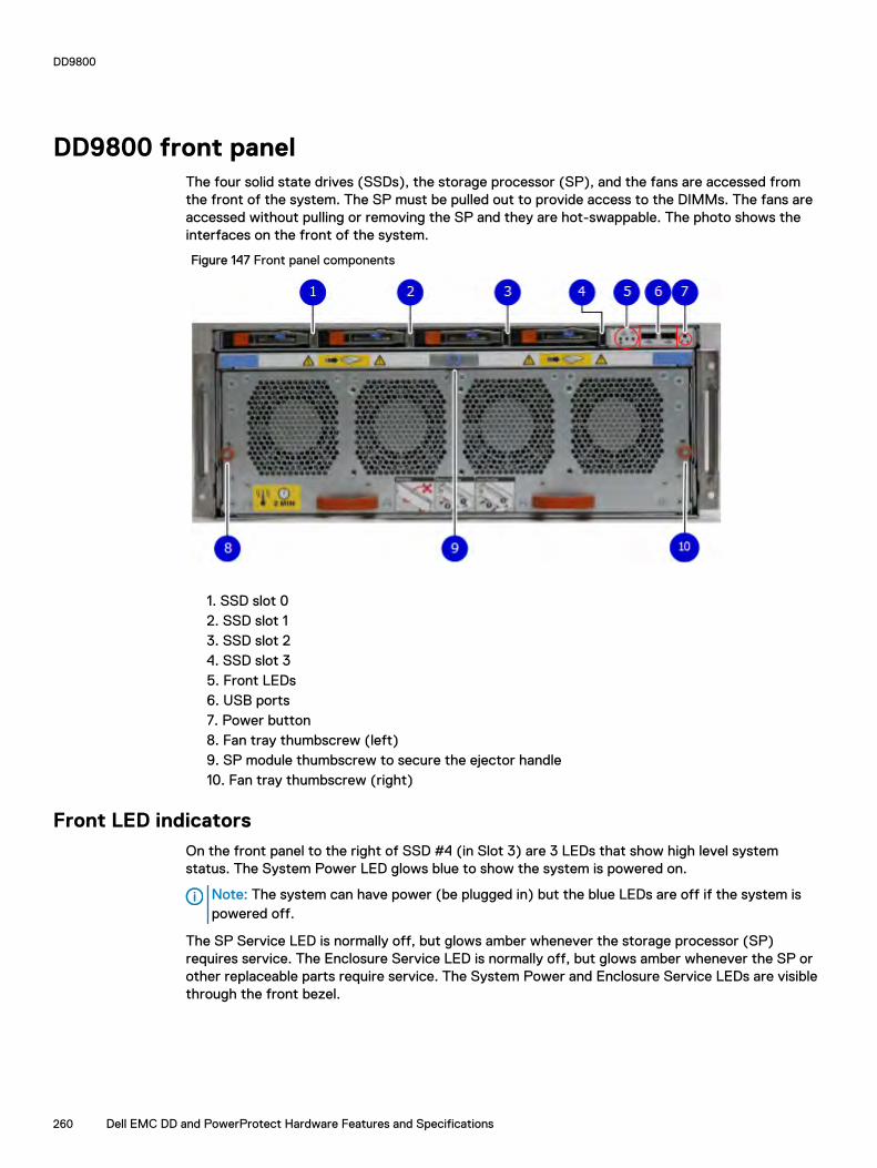
DD9800 front panelThe four solid state drives (SSDs), the storage processor (SP), and the fans are accessed fromthe front of the system. The SP must be pulled out to provide access to the DIMMs. The fans areaccessed without pulling or removing the SP and they are hot-swappable. The photo shows theinterfaces on the front of the system.
Figure 147 Front panel components
1. SSD slot 02. SSD slot 13. SSD slot 24. SSD slot 35. Front LEDs6. USB ports7. Power button8. Fan tray thumbscrew (left)9. SP module thumbscrew to secure the ejector handle10. Fan tray thumbscrew (right)
Front LED indicatorsOn the front panel to the right of SSD #4 (in Slot 3) are 3 LEDs that show high level systemstatus. The System Power LED glows blue to show the system is powered on.
Note: The system can have power (be plugged in) but the blue LEDs are off if the system ispowered off.
The SP Service LED is normally off, but glows amber whenever the storage processor (SP)requires service. The Enclosure Service LED is normally off, but glows amber whenever the SP orother replaceable parts require service. The System Power and Enclosure Service LEDs are visiblethrough the front bezel.
DD9800
260 Dell EMC DD and PowerProtect Hardware Features and Specifications

Figure 148 Service LEDs
1. SP service LED — Amber light indicates that the SP or one of its components needs service.2. Enclosure Service LED — This is normally off, but amber light indicates that the enclosure orsomething within the enclosure— the fans, SP, I/O modules, management module etc—requires service.3. System power LED — Blue light indicates system running
DD9800
Dell EMC DD and PowerProtect Hardware Features and Specifications 261
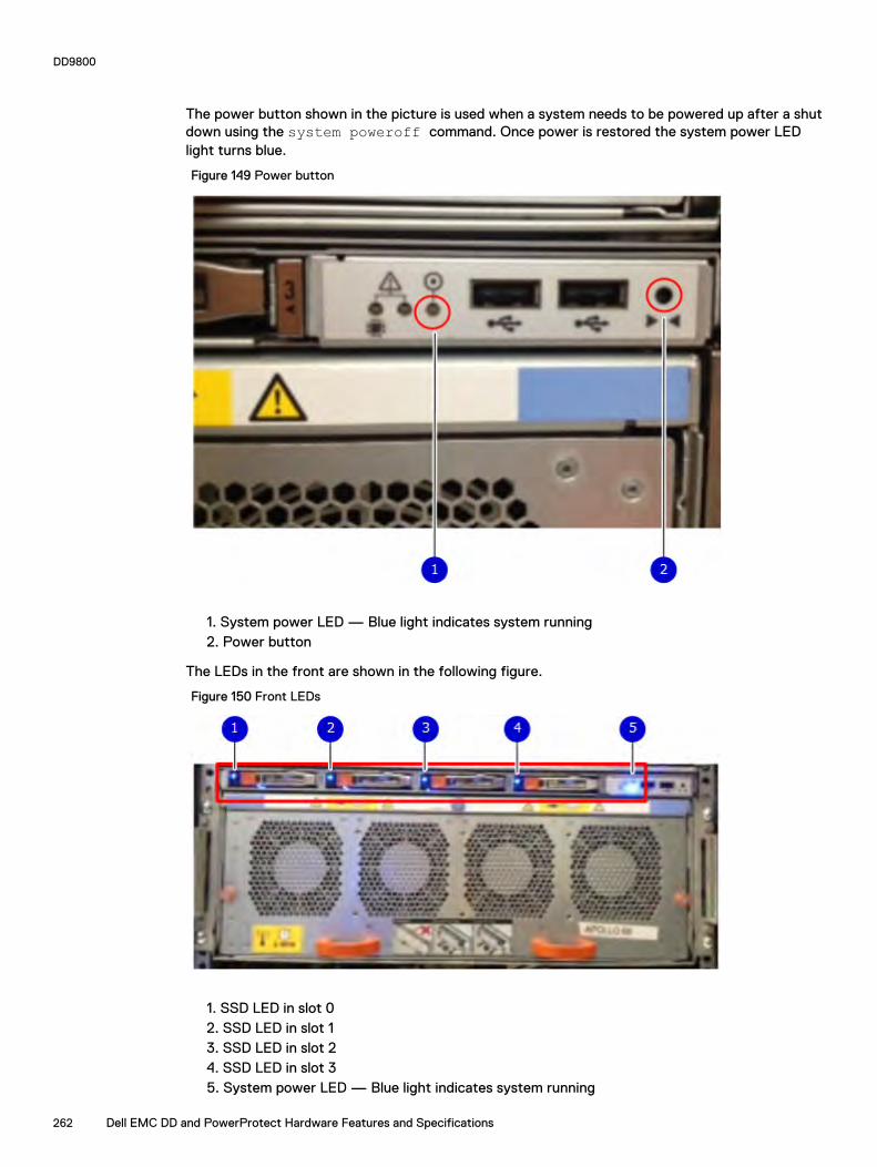
The power button shown in the picture is used when a system needs to be powered up after a shutdown using the system poweroff command. Once power is restored the system power LEDlight turns blue.
Figure 149 Power button
1. System power LED — Blue light indicates system running2. Power button
The LEDs in the front are shown in the following figure.
Figure 150 Front LEDs
1. SSD LED in slot 02. SSD LED in slot 13. SSD LED in slot 24. SSD LED in slot 35. System power LED — Blue light indicates system running
DD9800
262 Dell EMC DD and PowerProtect Hardware Features and Specifications

Table 171 Front panel LED status indicators
Part Description or Location State
System, SP fault Exclamation point within atriangle
Dark indicates normaloperation. Amber indicatesfailure.
System, chassis fault Exclamation point within atriangle
Dark indicates normaloperation. Amber indicates afault condition.
SSD Top LED Solid blue, disk ready, blinkswhile busy.
SSD Bottom LED Dark indicates healthy. Solidamber indicates disk fail.
Solid-state drivesA system contains 4 hot-swappable 2.5 in. 400 GB solid-state drives (SSD) located in the front.There are four drive bays numbered 0–3 from left to right. A dual drive failure allows the system tooperate without disruption.
Each drive has a blue colored power LED and an amber fault LED.
Figure 151 SSD drives
1. Slot 02. Slot 13. Slot 24. Slot 3
DD9800
Dell EMC DD and PowerProtect Hardware Features and Specifications 263

Rear panelIn the rear of the system, the top section contains the 4 power supply units. In the middle of thesection, on the left, is serial number tag location. To the right of the serial number tag location isthe management module. The lower section contains the NVRAM and the I/O modules numbered 0through 11 from left to right. The photo shows the hardware features and interfaces on the rear ofthe system.
Figure 152 Features on rear of chassis
1. Power supply units2. Serial number tag3. Management module4. NVRAM and I/O modules (slots 0-11)
The figure shows the location of the serial number tag on the left of the management module.
Figure 153 Serial number tag location
DD9800
264 Dell EMC DD and PowerProtect Hardware Features and Specifications
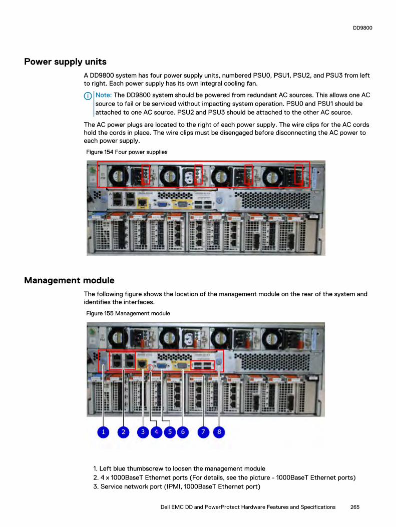
Power supply unitsA DD9800 system has four power supply units, numbered PSU0, PSU1, PSU2, and PSU3 from leftto right. Each power supply has its own integral cooling fan.
Note: The DD9800 system should be powered from redundant AC sources. This allows one ACsource to fail or be serviced without impacting system operation. PSU0 and PSU1 should beattached to one AC source. PSU2 and PSU3 should be attached to the other AC source.
The AC power plugs are located to the right of each power supply. The wire clips for the AC cordshold the cords in place. The wire clips must be disengaged before disconnecting the AC power toeach power supply.
Figure 154 Four power supplies
Management moduleThe following figure shows the location of the management module on the rear of the system andidentifies the interfaces.
Figure 155 Management module
1. Left blue thumbscrew to loosen the management module2. 4 x 1000BaseT Ethernet ports (For details, see the picture - 1000BaseT Ethernet ports)3. Service network port (IPMI, 1000BaseT Ethernet port)
DD9800
Dell EMC DD and PowerProtect Hardware Features and Specifications 265

4. Service LED5. VGA port6. Serial port7. Four USB ports8. Right blue thumbscrew to loosen the management module
Figure 156 1000BaseT Ethernet ports
- Lower left port: physical #0, logical ethMa- Top left port: physical #1, logical ethMb- Lower right port: physical #2, logical ethMc- Top right port: physical #3, logical ethMd
Rear LED indicators
The rear elements containing LEDs include each power supply, each I/O module, and themanagement module.
The figure shows the rear LEDS.
Figure 157 Rear LEDs
1. Management module service LEDs2. Power supply LEDs3. NVRAM LEDs
DD9800
266 Dell EMC DD and PowerProtect Hardware Features and Specifications

4. I/O Module LEDs
The power supply LEDs include:
l AC LED on top
l DC LED in the middle
l Service Required LED on the bottom
Figure 158 Power supply LEDs
Table 172 Rear LED status indicators
Part Description or Location State
Power supply AC LED Steady green indicates normalAC input power.
Power supply DC LED Steady green indicates normalDC output power.
Power supply Service LED Solid amber indicates a failedpower supply.
I/O module I/O module handle Solid green means I/O modulefunctioning normally. Amberindicates a fault condition.Each I/O module also has perport LEDs. These LEDs areblue on the FC, and SAS I/Omodules. They light when theport is active.
Management module Bicolor LED Solid green meansmanagement modulefunctioning normally. Amberindicates that themanagement module requiresservice.
Available I/O modulesI/O modules may include:
DD9800
Dell EMC DD and PowerProtect Hardware Features and Specifications 267
l Quad port Ethernet 10GBase-SR Optical with LC connectors
l Quad port Ethernet 10GBase-CX1 Direct Attach Copper with SPF+ module
l Quad port Ethernet 10GBase-T Copper
l Dual port 16 Gbps Fibre Channel
l Quad port 6 Gbps SAS
I/O module port physical mapping
I/O module ports are numbered starting with 0. When the I/O modules are inserted vertically intothe system chassis, port 0 is on the bottom.
I/O module port logical mapping
The numerical port labels on the I/O modules are identified logically in the DD OS software by thefollowing descriptions:
l I/O module type
l I/O module slot
l Alphabetic character corresponding to the physical port number
The following example is based on a four-port Ethernet I/O module installed in slot 1 of the systemchassis.
Table 173 Physical to logical port mapping example
Physical port Logical identifier
0 eth1a
1 eth1b
2 eth1c
3 eth1d
Ethernet I/O module optionsThe available Ethernet I/O modules are:
l Dual Port 10GBase-SR Optical with LC connectors
l Dual Port 10GBase-CX1 Direct Attach Copper with SPF+ module
l Quad Port 1000Base-T Copper with RJ-45 connectors
l Quad port 2 port 1000Base-T Copper (RJ45) /2 port 1000Base-SR Optical
Fibre Channel I/O modulesA Fibre Channel (FC) I/O module is a dual-port Fibre Channel module. Up to four FC I/O modulesmay be installed. The optional virtual tape library (VTL) feature requires at least one FC I/Omodule. Boost over Fibre Channel is an optional feature and requires at least one FC I/O module. Amaximum of four FC I/O modules may be installed in a system using either VTL or the Boostprotocol or a combination of both protocols.
DD9800
268 Dell EMC DD and PowerProtect Hardware Features and Specifications

SAS I/O modulesDD9800 systems have three quad-port SAS I/O modules installed in slots 2, 3 and 6. Systemsconfigured with DD Extended Retention (ER) or DD Cloud Tier software options require anadditional SAS I/O module in slot 9.
I/O module slot assignmentsThe following figure shows the location of the NVRAM and I/O modules.
Figure 159 Location of NVRAM and I/O modules
1. NVRAM module—slot 02. I/O modules—slots 1 to 11 (See the I/O module slot assignments table.)
The table shows the I/O module slot assignments for the DD9800 system. Each type of I/Omodule is restricted to certain slots.
Table 174 DD9800 I/O module slot assignments
Slot Baseconfiguration
HA ER or DD Cloud Tier DD Cloud Tier and HA
0 NVRAM NVRAM NVRAM NVRAM
1 Fibre Channel(FC), Ethernet orempty
Fibre Channel (FC),Ethernet or empty
Fibre Channel (FC),Ethernet or empty
Fibre Channel (FC),Ethernet or empty
2 SAS SAS SAS SAS
3 SAS SAS SAS SAS
4 FC, Ethernet orempty
FC, Ethernet orempty
FC, Ethernet or empty FC, Ethernet or empty
5 FC, Ethernet orempty
FC, Ethernet orempty
FC, Ethernet or empty FC, Ethernet or empty
6 SAS SAS SAS SAS
DD9800
Dell EMC DD and PowerProtect Hardware Features and Specifications 269
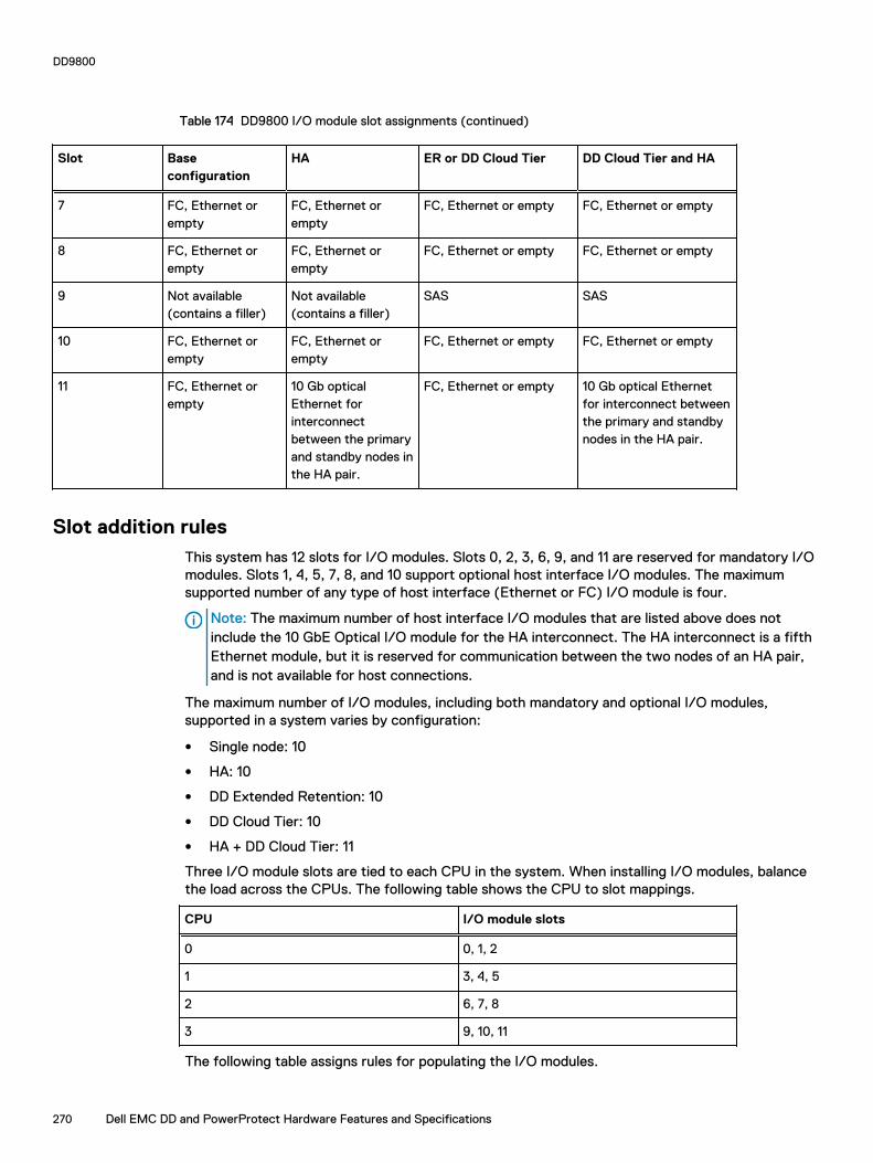
Table 174 DD9800 I/O module slot assignments (continued)
Slot Baseconfiguration
HA ER or DD Cloud Tier DD Cloud Tier and HA
7 FC, Ethernet orempty
FC, Ethernet orempty
FC, Ethernet or empty FC, Ethernet or empty
8 FC, Ethernet orempty
FC, Ethernet orempty
FC, Ethernet or empty FC, Ethernet or empty
9 Not available(contains a filler)
Not available(contains a filler)
SAS SAS
10 FC, Ethernet orempty
FC, Ethernet orempty
FC, Ethernet or empty FC, Ethernet or empty
11 FC, Ethernet orempty
10 Gb opticalEthernet forinterconnectbetween the primaryand standby nodes inthe HA pair.
FC, Ethernet or empty 10 Gb optical Ethernetfor interconnect betweenthe primary and standbynodes in the HA pair.
Slot addition rulesThis system has 12 slots for I/O modules. Slots 0, 2, 3, 6, 9, and 11 are reserved for mandatory I/Omodules. Slots 1, 4, 5, 7, 8, and 10 support optional host interface I/O modules. The maximumsupported number of any type of host interface (Ethernet or FC) I/O module is four.
Note: The maximum number of host interface I/O modules that are listed above does notinclude the 10 GbE Optical I/O module for the HA interconnect. The HA interconnect is a fifthEthernet module, but it is reserved for communication between the two nodes of an HA pair,and is not available for host connections.
The maximum number of I/O modules, including both mandatory and optional I/O modules,supported in a system varies by configuration:
l Single node: 10
l HA: 10
l DD Extended Retention: 10
l DD Cloud Tier: 10
l HA + DD Cloud Tier: 11
Three I/O module slots are tied to each CPU in the system. When installing I/O modules, balancethe load across the CPUs. The following table shows the CPU to slot mappings.
CPU I/O module slots
0 0, 1, 2
1 3, 4, 5
2 6, 7, 8
3 9, 10, 11
The following table assigns rules for populating the I/O modules.
DD9800
270 Dell EMC DD and PowerProtect Hardware Features and Specifications
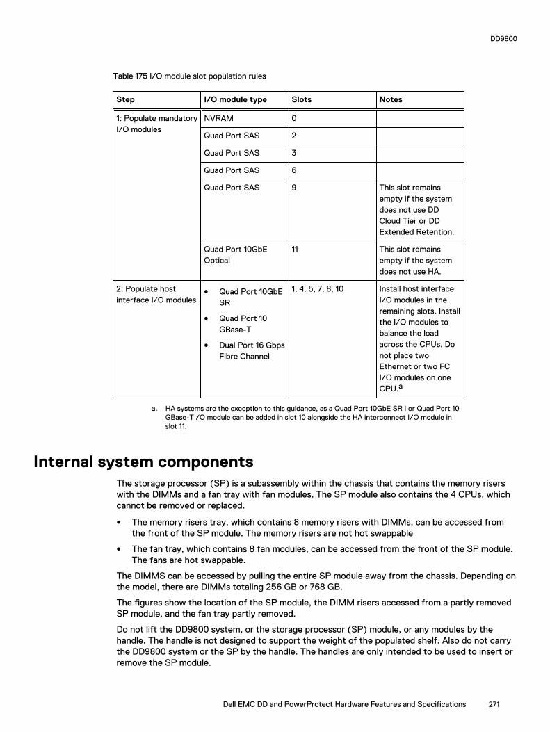
Table 175 I/O module slot population rules
Step I/O module type Slots Notes
1: Populate mandatoryI/O modules
NVRAM 0
Quad Port SAS 2
Quad Port SAS 3
Quad Port SAS 6
Quad Port SAS 9 This slot remainsempty if the systemdoes not use DDCloud Tier or DDExtended Retention.
Quad Port 10GbEOptical
11 This slot remainsempty if the systemdoes not use HA.
2: Populate hostinterface I/O modules
l Quad Port 10GbESR
l Quad Port 10GBase-T
l Dual Port 16 GbpsFibre Channel
1, 4, 5, 7, 8, 10 Install host interfaceI/O modules in theremaining slots. Installthe I/O modules tobalance the loadacross the CPUs. Donot place twoEthernet or two FCI/O modules on oneCPU.a
a. HA systems are the exception to this guidance, as a Quad Port 10GbE SR I or Quad Port 10GBase-T /O module can be added in slot 10 alongside the HA interconnect I/O module inslot 11.
Internal system componentsThe storage processor (SP) is a subassembly within the chassis that contains the memory riserswith the DIMMs and a fan tray with fan modules. The SP module also contains the 4 CPUs, whichcannot be removed or replaced.
l The memory risers tray, which contains 8 memory risers with DIMMs, can be accessed fromthe front of the SP module. The memory risers are not hot swappable
l The fan tray, which contains 8 fan modules, can be accessed from the front of the SP module.The fans are hot swappable.
The DIMMS can be accessed by pulling the entire SP module away from the chassis. Depending onthe model, there are DIMMs totaling 256 GB or 768 GB.
The figures show the location of the SP module, the DIMM risers accessed from a partly removedSP module, and the fan tray partly removed.
Do not lift the DD9800 system, or the storage processor (SP) module, or any modules by thehandle. The handle is not designed to support the weight of the populated shelf. Also do not carrythe DD9800 system or the SP by the handle. The handles are only intended to be used to insert orremove the SP module.
DD9800
Dell EMC DD and PowerProtect Hardware Features and Specifications 271

Figure 160 SP module
Figure 161 Releasing a memory riser
1. Left riser card ejector handle2. Release button3. Right riser card ejector handle
DD9800
272 Dell EMC DD and PowerProtect Hardware Features and Specifications
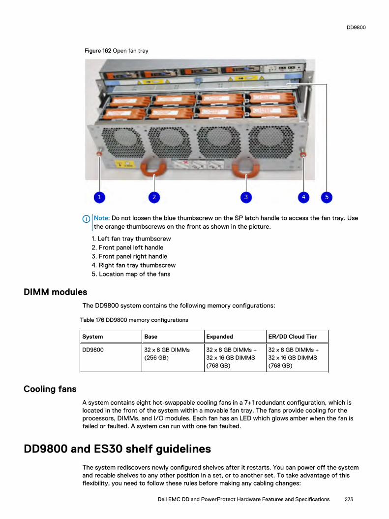
Figure 162 Open fan tray
Note: Do not loosen the blue thumbscrew on the SP latch handle to access the fan tray. Usethe orange thumbscrews on the front as shown in the picture.
1. Left fan tray thumbscrew2. Front panel left handle3. Front panel right handle4. Right fan tray thumbscrew5. Location map of the fans
DIMM modulesThe DD9800 system contains the following memory configurations:
Table 176 DD9800 memory configurations
System Base Expanded ER/DD Cloud Tier
DD9800 32 x 8 GB DIMMs(256 GB)
32 x 8 GB DIMMs +32 x 16 GB DIMMS(768 GB)
32 x 8 GB DIMMs +32 x 16 GB DIMMS(768 GB)
Cooling fansA system contains eight hot-swappable cooling fans in a 7+1 redundant configuration, which islocated in the front of the system within a movable fan tray. The fans provide cooling for theprocessors, DIMMs, and I/O modules. Each fan has an LED which glows amber when the fan isfailed or faulted. A system can run with one fan faulted.
DD9800 and ES30 shelf guidelines
The system rediscovers newly configured shelves after it restarts. You can power off the systemand recable shelves to any other position in a set, or to another set. To take advantage of thisflexibility, you need to follow these rules before making any cabling changes:
DD9800
Dell EMC DD and PowerProtect Hardware Features and Specifications 273
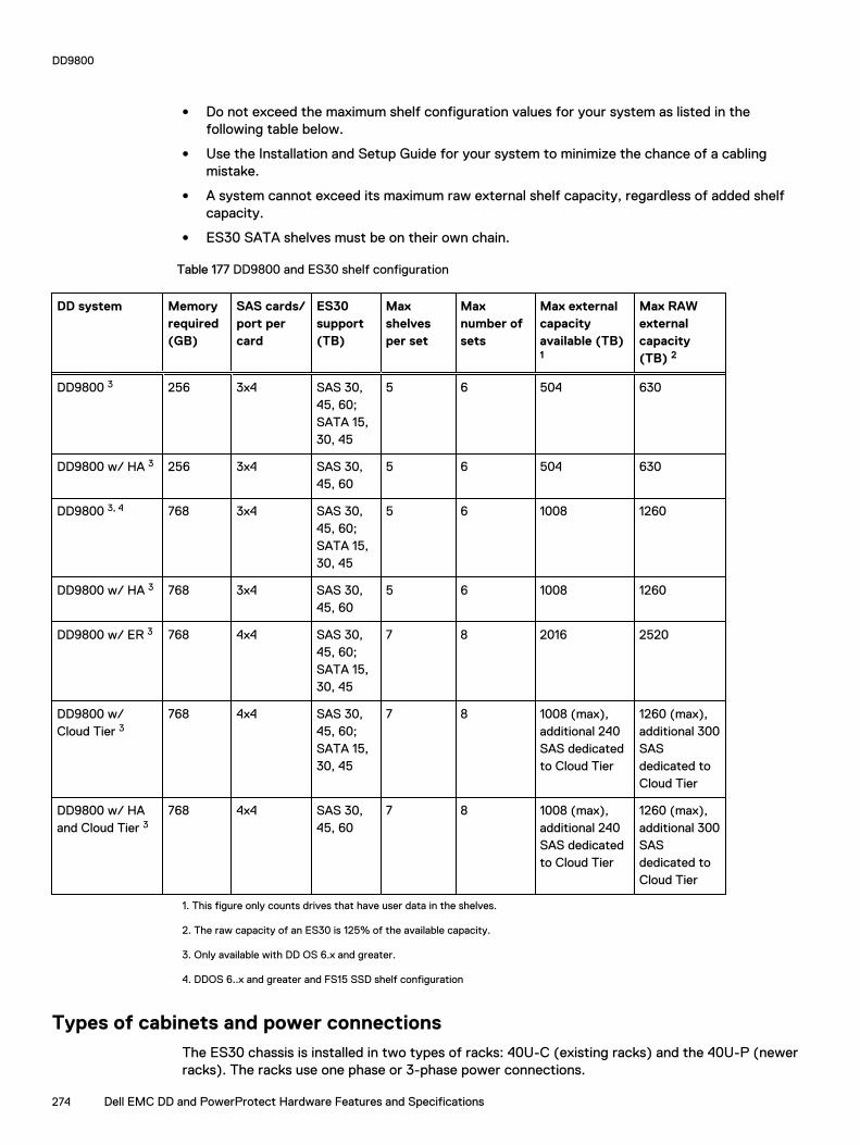
l Do not exceed the maximum shelf configuration values for your system as listed in thefollowing table below.
l Use the Installation and Setup Guide for your system to minimize the chance of a cablingmistake.
l A system cannot exceed its maximum raw external shelf capacity, regardless of added shelfcapacity.
l ES30 SATA shelves must be on their own chain.
Table 177 DD9800 and ES30 shelf configuration
DD system Memoryrequired(GB)
SAS cards/port percard
ES30support(TB)
Maxshelvesper set
Maxnumber ofsets
Max externalcapacityavailable (TB)1
Max RAWexternalcapacity(TB) 2
DD9800 3 256 3x4 SAS 30,45, 60;SATA 15,30, 45
5 6 504 630
DD9800 w/ HA 3 256 3x4 SAS 30,45, 60
5 6 504 630
DD9800 3, 4 768 3x4 SAS 30,45, 60;SATA 15,30, 45
5 6 1008 1260
DD9800 w/ HA 3 768 3x4 SAS 30,45, 60
5 6 1008 1260
DD9800 w/ ER 3 768 4x4 SAS 30,45, 60;SATA 15,30, 45
7 8 2016 2520
DD9800 w/Cloud Tier 3
768 4x4 SAS 30,45, 60;SATA 15,30, 45
7 8 1008 (max),additional 240SAS dedicatedto Cloud Tier
1260 (max),additional 300SASdedicated toCloud Tier
DD9800 w/ HAand Cloud Tier 3
768 4x4 SAS 30,45, 60
7 8 1008 (max),additional 240SAS dedicatedto Cloud Tier
1260 (max),additional 300SASdedicated toCloud Tier
1. This figure only counts drives that have user data in the shelves.
2. The raw capacity of an ES30 is 125% of the available capacity.
3. Only available with DD OS 6.x and greater.
4. DDOS 6..x and greater and FS15 SSD shelf configuration
Types of cabinets and power connectionsThe ES30 chassis is installed in two types of racks: 40U-C (existing racks) and the 40U-P (newerracks). The racks use one phase or 3-phase power connections.
DD9800
274 Dell EMC DD and PowerProtect Hardware Features and Specifications
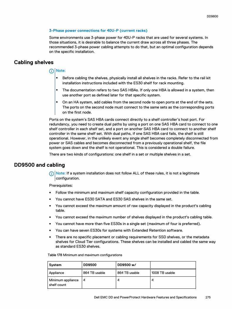
3-Phase power connections for 40U-P (current racks)
Some environments use 3-phase power for 40U-P racks that are used for several systems. Inthose situations, it is desirable to balance the current draw across all three phases. Therecommended 3-phase power cabling attempts to do that, but an optimal configuration dependson the specific installation.
Cabling shelves
Note:
l Before cabling the shelves, physically install all shelves in the racks. Refer to the rail kitinstallation instructions included with the ES30 shelf for rack mounting.
l The documentation refers to two SAS HBAs. If only one HBA is allowed in a system, thenuse another port as defined later for that specific system.
l On an HA system, add cables from the second node to open ports at the end of the sets.The ports on the second node must connect to the same sets as the corresponding portson the first node.
Ports on the system’s SAS HBA cards connect directly to a shelf controller’s host port. Forredundancy, you need to create dual paths by using a port on one SAS HBA card to connect to oneshelf controller in each shelf set, and a port on another SAS HBA card to connect to another shelfcontroller in the same shelf set. With dual paths, if one SAS HBA card fails, the shelf is stilloperational. However, in the unlikely event any single shelf becomes completely disconnected frompower or SAS cables and becomes disconnected from a previously operational shelf, the filesystem goes down and the shelf is not operational. This is considered a double failure.
There are two kinds of configurations: one shelf in a set or multiple shelves in a set.
DD9500 and cabling
Note: If a system installation does not follow ALL of these rules, it is not a legitimateconfiguration.
Prerequisites:
l Follow the minimum and maximum shelf capacity configuration provided in the table.
l You cannot have ES30 SATA and ES30 SAS shelves in the same set.
l You cannot exceed the maximum amount of raw capacity displayed in the product's cablingtable.
l You cannot exceed the maximum number of shelves displayed in the product's cabling table.
l You cannot have more than five ES30s in a single set (maximum of four is preferred).
l You can have seven ES30s for systems with Extended Retention software.
l There are no specific placement or cabling requirements for SSD shelves, or the metadatashelves for Cloud Tier configurations. These shelves can be installed and cabled the same wayas standard ES30 shelves.
Table 178 Minimum and maximum configurations
System DD9500 DD9500 w/
Appliance 864 TB usable 864 TB usable 1008 TB usable
Minimum applianceshelf count
4 4 4
DD9800
Dell EMC DD and PowerProtect Hardware Features and Specifications 275

Table 178 Minimum and maximum configurations (continued)
System DD9500 DD9500 w/
Maximum applianceshelf count
30 30 30
Extended Retentionsystems (ER)
1728 TB usable 2016 TB usable 2016 TB usable
Maximum shelvesfor ER
56 56 56
High Availabilitysystems (HA)
864 TB usable 1008 TB usable 1008 TB usable
Maximum shelvesfor HA
42 42 47
Cloud Tier systems 1104 TB usable 1248 TB usable 1248 TB usable
Maximum shelvesfor Cloud Tier
42 42 47
The DD9500 base (non-Extended Retention) and HA systems supports six chains.
The following figures show cabling for base systems, HA systems, and systems with the ExtendedRetention software option.
Note: The racks are filled from bottom up.
DD9800 and DS60 shelf guidelines
The system rediscovers newly configured shelves after it restarts. You can power off the systemand recable shelves to any other position in a set, or to another set. To take advantage of thisflexibility, you need to follow these rules before making any cabling changes:
l Do not exceed the maximum shelf configuration values for your system as listed in thefollowing table.
l For redundancy, the two connections from a system to a set of shelves must use ports ondifferent SAS I/O modules.
l Use the Installation and Setup Guide for your system to minimize the chance of a cablingmistake.
l A system cannot exceed its maximum raw external shelf capacity, regardless of added shelfcapacity.
l ES30 SATA shelves must be on their own chain.
l If ES30 SAS shelves are on the same chain as a DS60, the maximum number of shelves on thatchain is 5.
DD9800
276 Dell EMC DD and PowerProtect Hardware Features and Specifications

Table 179 DD9800 and DS60 shelf configuration
DD system Memoryrequired(GB)
SAScards/port percard
DS60 support(TB)
Maxshelvesper set
Maxnumber ofsets
Maxexternalcapacityavailable(TB)1
Max RAWexternalcapacity(TB)
DD9800 2, 3 256 3x4 SAS 45, 60 4 6 504 630
DD9800 w/ HA2, 3 256 3x4 SAS 45, 60 4 6 504 630
DD9800 2, 3 768 3x4 SAS 45, 60 4 6 1008 1260
DD9800 w/HA 2, 3 768 3x4 SAS 45, 60 4 6 1008 1260
DD9800 ER 2, 3 768 4x4 SAS 45, 60 4 8 2016 2520
DD9800 CloudTier 2, 3
768 4x4 SAS 45, 60 5 8 1008 + 240for CloudTier
1260 + 300for Cloud Tier
DD9800 CloudTier w/ HA 2, 3, 4
768 4x4 SAS 45, 60 5 8 1008 + 240for CloudTier
1260 + 300for Cloud Tier
Note: An entry of 45 corresponds to DS60-3 models and an entry of 60 corresponds toDS60-4 models.
1. This column only counts drives that have user data in the shelves. For example, a DS60 4-240 has 192TB.
2. With DD OS 6.x and greater with SSD.
3. Only available with DD OS 6.x and greater.
4. With Cloud Tier Storage.
3-phase power connections for 40U-P (current racks)Some environments use 3-phase power for 40U-P racks used for several systems. In thosesituations it is desirable to balance the current draw across all 3 phases. The recommended 3-phase power cabling attempts to do that, but an optimal configuration is dependent on the specificinstallation.
DD9500 and DD9800 cabling
Note: If a system installation does not follow ALL of these rules, it is not a legitimateconfiguration.
Prerequisites:
l Follow the minimum and maximum shelf capacity configuration provided in the table.
l You cannot have ES30 SATA and ES30 SAS shelves in the same set.
l You cannot exceed the maximum amount of raw capacity displayed in the product's cablingtable.
l You cannot exceed the maximum number of shelves displayed in the product's cabling table.
l You cannot have more than five ES30s in a single set (maximum of four is preferred).
l You can have seven ES30s for systems with Extended Retention software.
DD9800
Dell EMC DD and PowerProtect Hardware Features and Specifications 277
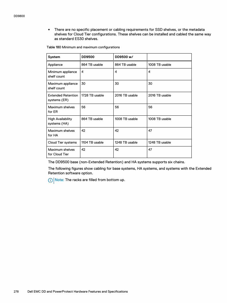
l There are no specific placement or cabling requirements for SSD shelves, or the metadatashelves for Cloud Tier configurations. These shelves can be installed and cabled the same wayas standard ES30 shelves.
Table 180 Minimum and maximum configurations
System DD9500 DD9500 w/
Appliance 864 TB usable 864 TB usable 1008 TB usable
Minimum applianceshelf count
4 4 4
Maximum applianceshelf count
30 30 30
Extended Retentionsystems (ER)
1728 TB usable 2016 TB usable 2016 TB usable
Maximum shelvesfor ER
56 56 56
High Availabilitysystems (HA)
864 TB usable 1008 TB usable 1008 TB usable
Maximum shelvesfor HA
42 42 47
Cloud Tier systems 1104 TB usable 1248 TB usable 1248 TB usable
Maximum shelvesfor Cloud Tier
42 42 47
The DD9500 base (non-Extended Retention) and HA systems supports six chains.
The following figures show cabling for base systems, HA systems, and systems with the ExtendedRetention software option.
Note: The racks are filled from bottom up.
DD9800
278 Dell EMC DD and PowerProtect Hardware Features and Specifications
CHAPTER 12
DD9900
This chapter contains the following topics:
l DD9900 system features.....................................................................................................280l DD9900 system specifications.............................................................................................281l DD9900 storage capacity and configurations...................................................................... 282l DD9900 front panel.............................................................................................................283l DD9900 SSD usage and configurations...............................................................................286l DD9900 rear panel...............................................................................................................287l PCIe HBAs...........................................................................................................................288l DD9900 DIMM configurations.............................................................................................290l DD6900, DD9400, and DD9900 storage shelves configurations and capacities................... 291
Dell EMC DD and PowerProtect Hardware Features and Specifications 279

DD9900 system features
Table 181 DD9900 system features
Configurations Single Node HA A-P
Processor 4 x Intel Xeon Gold, 2294 Mhz, 18C
Kernel 4.4
MemoryConfigurations
Total 1152 GB
DIMMs 24 x 16 GB + 24 x 32 GB
HDD Drive Size 8TB (shipped, 3TB and 4TB also supported)
SupportedCapacity
Active Tier 576 <-> 1248 TBu
Cloud Tier 2016 TBu (Cloud Tier)
Disk Groups Active Tier 6 <-> 16
Over Provisioning 2
Cloud Tier (4 TB) 5
SSDs for OS in 2.5" bays in head 4, 1.92TB, 1 WPD
Stream Count 1885 Wr, 300 Rd
Cache SSDs 2.5% 10 (External) 3.84 TB
Cache SSD shelf FS25 1
HA Private Interconnect N/A (3) 10G Base-T ports(NDC)
16 GB NVRAM 1
HW Accelerator 100 Quick AssistTechnology (QAT)8970
2
Internal SAS PowerEdge RaidController (PERC)H330+ 12 GbpsSAS
1
External SAS PMC Quad Port 12Gbps SAS
2 default, 3 supported
SAS String Depth(max)
ES30/ES40 7
DS60 3
Host interfaceHBAs
2-port 100 GbE-QSFP28
4 maximum
2-port QL41000 25GbE-SFP28
4 maximum
4-port QL41164 10GbE-SFP+
4 maximum
DD9900
280 Dell EMC DD and PowerProtect Hardware Features and Specifications

Table 181 DD9900 system features (continued)
Configurations Single Node HA A-P
4-port QL4116410GBASE-T
4 maximum
4-port QLE2694 16Gb FC
4 maximum
Network DaughterCard options (oneof these 2)
4-port QL41000 10GbE-SP+ FasLinQ
1
4-port QL4116410GBASE-T
1
DD9900 system specifications
Figure 163 System dimensions
Table 182 DD9900 system specifications
Xa Xb Y Za (withbezel)
Za (withoutbezel)
Zb Zc
482.0 mm(18.98 inches)
434.0 mm(17.09 inches)
130.3 mm(5.13 inches)
35.0 mm (1.37inches)
22.0 mm (0.87inches)
726.2 mm(28.59 inches)
777.046 mm(30.59 inches)
A DD9900 system weighs up to 110.01 lbs (49.9 kg).
DD9900
Dell EMC DD and PowerProtect Hardware Features and Specifications 281

Table 183 System operating environment
Operating Temperature 50° to 95° F (10° to 35° C), derate 1.1° Cper 1000 feet, above 7500 feet up to 10,000feet (32.25° C at 10,000)
Operating Humidity 20% to 80%, non-condensing
Non-operating Temperature -40° to +149° F (-40° to +65° C)
Operating Acoustic Noise L wad sound power, 7.5 Bels
DD9900 storage capacity and configurationsThe following table provides storage capacity and configuration information for the DD9900system.
Table 184 DD9900 storage capacity and configurations
Tier CPU-SP SKU Memory Front 2.5" SSDs Max. UseableCapacity
DD9900 Base 18 core, 150 W6240
1152 GB (24 x 16GB) + (24 x 32GB)
10 1248TBu
DD9900 with DDCloud Tier 1
18 core, 150 W6240
1152 GB (24 x 16GB) + (24 x 32GB)
10 2016TBu
1 DD Cloud Tier can be added to a DD9900 and is enabled by a license and disk packs for the DDCloud Tier metadata.
The Memory column lists the total memory that is required and the number and type of the DIMMsused. All memory DIMMs are DDR4 RDIMMs at the highest supported speed of 2666MT/s.
High Availability
DD9900 supports Active-Passive High Availability (A-P HA or just A-P). The following tablesummarizes the hardware changes to support A-P HA:
Table 185 HA configuration requirements
Hardware Changeto support HA
Active-Passive HA
Additional memory No extra memory required.
HA privateinterconnect
Cluster Interconnect : A-P requires the use of two ports from the on-board quad-port 10 GbE Network Daughter Card.
NVRAM A-P requires a single 16 GB NVRAM card (same as non-HA).
SAS Connectivity Both nodes of an A-P HA pair require redundant SAS connectivity tothe storage array. (Note: a single node system also has redundantconnectivity to the storage arrays.)
SSD Requirements SSDs are contained within FS25 and must be accessible from bothnodes.
DD9900
282 Dell EMC DD and PowerProtect Hardware Features and Specifications

HA Network Interconnect
The HA Network Interconnect, required for HA configurations, is a dedicated 10 GbE connectionbetween the two nodes of an HA pair. The interconnect is used to write data (and metadata) fromthe active node's NVRAM to the passive node's NVRAM.
Two 10GbE links are used to meet the bandwidth requirements for the private interconnect.Traffic across the private interconnect has roughly the same bandwidth as is written to theNVRAM card. The dual 10-GbE links can move about 2 GB/s in each direction.
HA SAS Interconnect
HA configurations require that the SSDs' cache drives be shared between both nodes and haveredundant SAS connections to all shelves.
DD9900 front panel
Figure 164 DD9900 front panel
Table 186 Front panel features
Item
Ports, panels, andslots
Description
1 Left control panel Contains system health and system ID, status LED, andoptional iDRAC Quick Sync 2 (wireless).
2 Drive slots Enable you to install drives that are supported on yoursystem.
3 Right control panel Contains the power button, VGA port, iDRAC Direct port, andUSB ports.
4 Information tag The Information tag is a slide-out label panel that containssystem information such as Service Tag, NIC, MAC address,and so on. If you have opted for the secure default access toiDRAC, the Information tag also contains the iDRAC securedefault password.
5 Drive bay Hard drive bay
Table 187 Front LEDs
Name Color Purpose
Control Panel Status LED Blue/Amber Status:
l Healthy: Solid Blue
DD9900
Dell EMC DD and PowerProtect Hardware Features and Specifications 283

Table 187 Front LEDs (continued)
Name Color Purpose
l Fault: Blink Amber
l Sys ID: Blink Blue
System Power Button/LED Green Indication that the system has power.
Drive activity LEDs Green Lit green when the drive is powered. Blinksduring drive activity.
Drive service LEDs Green Lit solid amber when a disk drive needsservice.
Front LEDs
Figure 165 Front left control panel status LEDs
Note: The indicators display solid amber if any error occurs.
Table 188 System health and system ID indicator codes
System health and IDindicator code
Solid blue Indicates that the system is turned on, system is healthy, andsystem ID mode is not active. Press the system health andsystem ID button to switch to system ID mode.
Blinking blue Indicates that the system ID mode is active. Press thesystem health and system ID button to switch to systemhealth mode.
Solid amber Indicates that the system is in fail-safe mode.
Blinking amber Indicates that the system is experiencing a fault. Check theSystem event log or the LCD panel, if available on the bezel,for specific error messages.
DD9900
284 Dell EMC DD and PowerProtect Hardware Features and Specifications
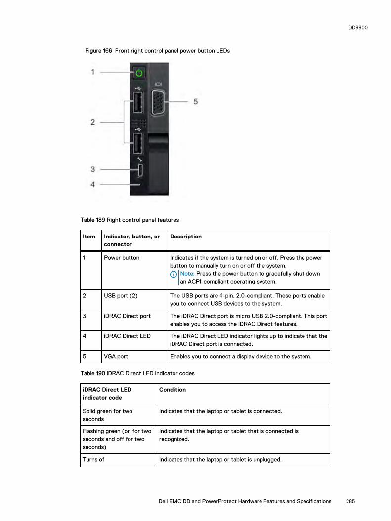
Figure 166 Front right control panel power button LEDs
Table 189 Right control panel features
Item Indicator, button, orconnector
Description
1 Power button Indicates if the system is turned on or off. Press the powerbutton to manually turn on or off the system.
Note: Press the power button to gracefully shut downan ACPI-compliant operating system.
2 USB port (2) The USB ports are 4-pin, 2.0-compliant. These ports enableyou to connect USB devices to the system.
3 iDRAC Direct port The iDRAC Direct port is micro USB 2.0-compliant. This portenables you to access the iDRAC Direct features.
4 iDRAC Direct LED The iDRAC Direct LED indicator lights up to indicate that theiDRAC Direct port is connected.
5 VGA port Enables you to connect a display device to the system.
Table 190 iDRAC Direct LED indicator codes
iDRAC Direct LEDindicator code
Condition
Solid green for twoseconds
Indicates that the laptop or tablet is connected.
Flashing green (on for twoseconds and off for twoseconds)
Indicates that the laptop or tablet that is connected isrecognized.
Turns of Indicates that the laptop or tablet is unplugged.
DD9900
Dell EMC DD and PowerProtect Hardware Features and Specifications 285
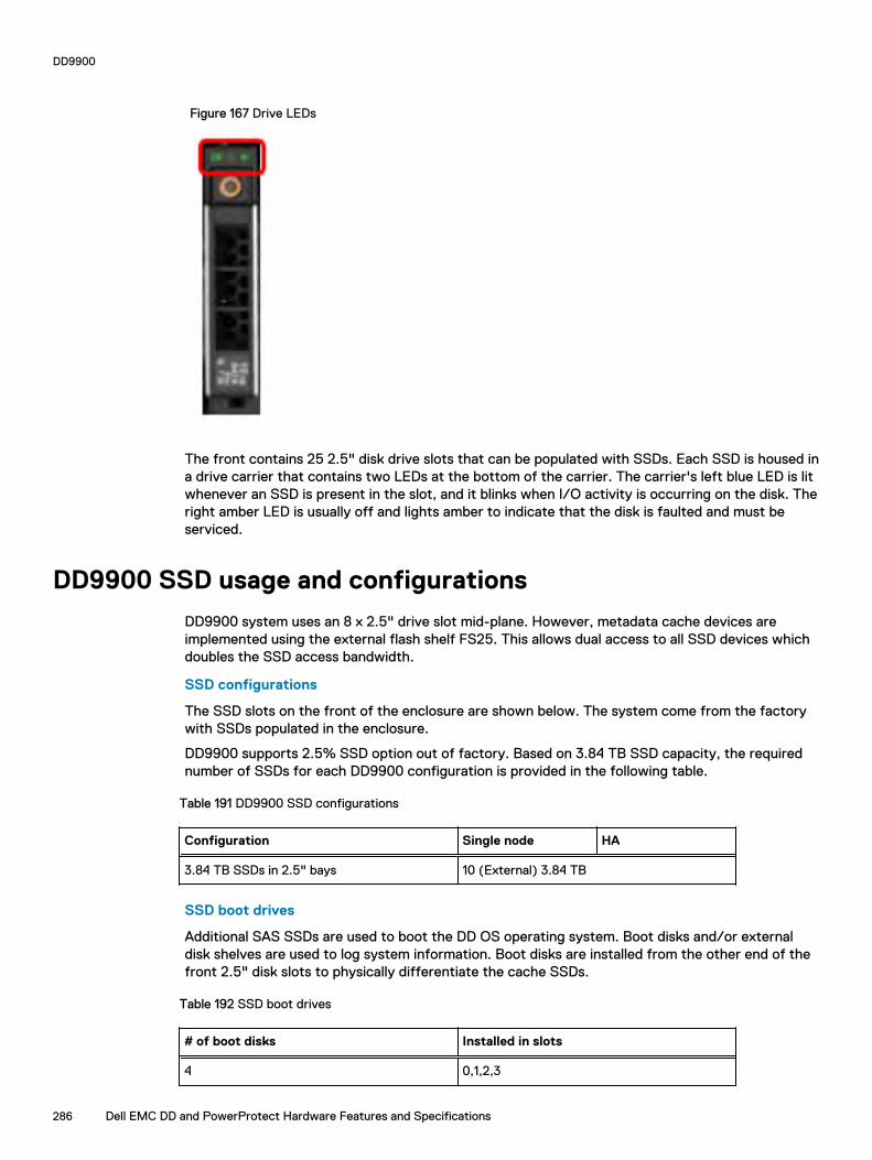
Figure 167 Drive LEDs
The front contains 25 2.5" disk drive slots that can be populated with SSDs. Each SSD is housed ina drive carrier that contains two LEDs at the bottom of the carrier. The carrier's left blue LED is litwhenever an SSD is present in the slot, and it blinks when I/O activity is occurring on the disk. Theright amber LED is usually off and lights amber to indicate that the disk is faulted and must beserviced.
DD9900 SSD usage and configurations
DD9900 system uses an 8 x 2.5" drive slot mid-plane. However, metadata cache devices areimplemented using the external flash shelf FS25. This allows dual access to all SSD devices whichdoubles the SSD access bandwidth.
SSD configurations
The SSD slots on the front of the enclosure are shown below. The system come from the factorywith SSDs populated in the enclosure.
DD9900 supports 2.5% SSD option out of factory. Based on 3.84 TB SSD capacity, the requirednumber of SSDs for each DD9900 configuration is provided in the following table.
Table 191 DD9900 SSD configurations
Configuration Single node HA
3.84 TB SSDs in 2.5" bays 10 (External) 3.84 TB
SSD boot drives
Additional SAS SSDs are used to boot the DD OS operating system. Boot disks and/or externaldisk shelves are used to log system information. Boot disks are installed from the other end of thefront 2.5" disk slots to physically differentiate the cache SSDs.
Table 192 SSD boot drives
# of boot disks Installed in slots
4 0,1,2,3
DD9900
286 Dell EMC DD and PowerProtect Hardware Features and Specifications

DD9900 rear panel
Figure 168 DD9900 rear panel
Item Slot, button, orconnector
Description
1 Half-height PCIeexpansion card slot
The PCIe expansion card slot connects one half-height PCIeexpansion cards to the system.
2 Full-height PCIeexpansion slots
The PCIe expansion card slot connects up to three full-heightPCIe expansion cards to the system.
3 NIC ports (4) The NIC ports that are integrated on the network daughtercard (NDC) provide network connectivity.
4 Half-height PCIeexpansion card slot
The PCIe expansion card slot connects one half-height PCIeexpansion cards to the system.
5 Power supply unit (2) Supports up to two AC or DC power supply units (PSUs)
6 VGA port Enables you to connect a display device to the system.
7 Serial port Enables you to connect a serial device to the system.
8 iDRAC9 Enterprise port Enables you to remotely access iDRAC.
9 USB port (2) The USB ports are 9-pin and 3.0-compliant. These portsenable you to connect USB devices to the system.
10 System identificationbutton
The System Identification (ID) button is available on the frontand back of the systems. Press the button to identify asystem in a rack by turning on the system ID button. You canalso use the system ID button to reset iDRAC and to accessBIOS using the step through mode.
11 Status indicator cableport
Enables you to connect the status indicator cable and viewsystem status when the CMA is installed.
DD9900
Dell EMC DD and PowerProtect Hardware Features and Specifications 287

Rear LEDs
Figure 169 Onboard ID and iDRAC LEDs
1. iDRAC management port:
a. The green link LED on the left is lit whenever there is link at 1000BaseT and 100BaseTspeeds. The link LED is off when the link speed is 10BaseT or there is no link.
b. The green link LED on the right blinks whenever there is traffic on the port.
2. System identification LED: This blue LED can be turned on by software to visually identify thesystem.
PSU FRU LEDs
There are two power supplies, one in the upper left of the rear chassis and one on the bottomright. Each power supply has three LEDs: AC good, DC good, and Service. The top PSU is "right-side up" and the bottom PSU is "upside down."
Table 193 PSU FRU LEDs
Name Color Definition
AC Good Green AC input is as expected.
DC Good Green DC output is as expected.
Service Amber PSU has a fault condition anda must be replaced.
PCIe HBAs
A slot in the chassis that does not contain an HBA must have a filler panel installed in the emptyslots. This is required for EMI compliance.
This system supports eight I/O modules slots, 4 of which are 8-lane PCIe Gen3, and two are 16-lane PCIe Gen3. Several networking, NVRAM, SAS, and Fibre Channel I/O modules are supported.
DD9900
288 Dell EMC DD and PowerProtect Hardware Features and Specifications
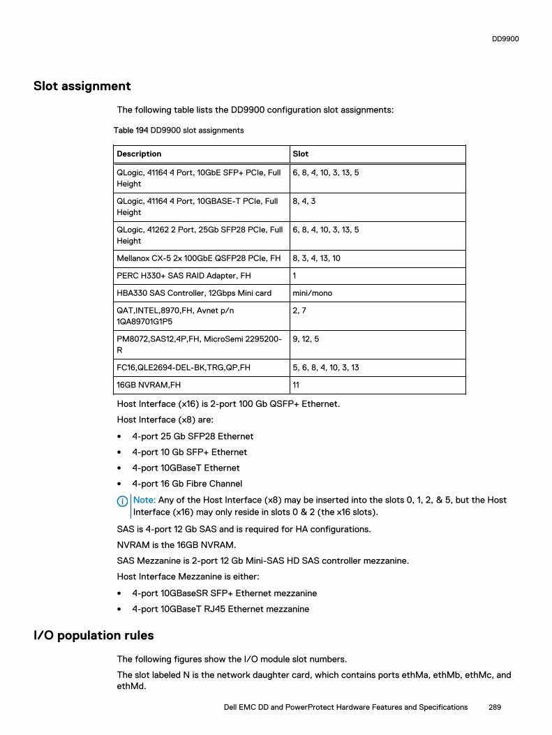
Slot assignment
The following table lists the DD9900 configuration slot assignments:
Table 194 DD9900 slot assignments
Description Slot
QLogic, 41164 4 Port, 10GbE SFP+ PCIe, FullHeight
6, 8, 4, 10, 3, 13, 5
QLogic, 41164 4 Port, 10GBASE-T PCIe, FullHeight
8, 4, 3
QLogic, 41262 2 Port, 25Gb SFP28 PCIe, FullHeight
6, 8, 4, 10, 3, 13, 5
Mellanox CX-5 2x 100GbE QSFP28 PCIe, FH 8, 3, 4, 13, 10
PERC H330+ SAS RAID Adapter, FH 1
HBA330 SAS Controller, 12Gbps Mini card mini/mono
QAT,INTEL,8970,FH, Avnet p/n1QA89701G1P5
2, 7
PM8072,SAS12,4P,FH, MicroSemi 2295200-R
9, 12, 5
FC16,QLE2694-DEL-BK,TRG,QP,FH 5, 6, 8, 4, 10, 3, 13
16GB NVRAM,FH 11
Host Interface (x16) is 2-port 100 Gb QSFP+ Ethernet.
Host Interface (x8) are:
l 4-port 25 Gb SFP28 Ethernet
l 4-port 10 Gb SFP+ Ethernet
l 4-port 10GBaseT Ethernet
l 4-port 16 Gb Fibre Channel
Note: Any of the Host Interface (x8) may be inserted into the slots 0, 1, 2, & 5, but the HostInterface (x16) may only reside in slots 0 & 2 (the x16 slots).
SAS is 4-port 12 Gb SAS and is required for HA configurations.
NVRAM is the 16GB NVRAM.
SAS Mezzanine is 2-port 12 Gb Mini-SAS HD SAS controller mezzanine.
Host Interface Mezzanine is either:
l 4-port 10GBaseSR SFP+ Ethernet mezzanine
l 4-port 10GBaseT RJ45 Ethernet mezzanine
I/O population rules
The following figures show the I/O module slot numbers.
The slot labeled N is the network daughter card, which contains ports ethMa, ethMb, ethMc, andethMd.
DD9900
Dell EMC DD and PowerProtect Hardware Features and Specifications 289

The physical interface name format for the other I/O module slots is ethXy, where X is the slotnumber and y is an alphanumeric character. For example, eth0a.
For most horizontal I/O module NIC interfaces, the port numbering goes from left to right, withethXa on the left. The horizontal I/O module slots on the left-in slots 11-13 are inverted. The portnumbering on these I/O modules in these slots goes from right to left, with ethXa on the right.
For vertical I/O module NIC interfaces, the port numbering goes from top to bottom, with ethXa atthe top.
The management port ethMa is the first port set up by the Configuration Wizard. It is marked witha red rectangle in the figure below.
Figure 170 Slot numbering
The general population rules can be summarized as:
1. Populate a given I/O in the available slots listed.
2. Select the first available slot in the group.
3. Follow the steps for each I/O in the order specified.
4. Slots 0 and 2 should be reserved for x16 unless there are no available x8 slots.
Note: Installing HBAs requires opening the system and installing the HBA into the riser.
Riser# Slots (from top to bottom)
Left 11, 12, 13
Right 8, 9, 10
Slots 1, N, 2, 3, 4, 5, 6, and 7 are not installed on a riser.
Gen3 PCIe
Slots support Gen3 PCIe.
I/O module servicing
All I/O modules are user serviceable and may be replaced when the system is powered off. On-lineservice of I/O modules is not support. A module that is hot-inserted into the system will remainpowered off and will not be powered on until the next reboot of the system. A module that is hot-removed causes an operating system to immediately reboot.
DD9900 DIMM configurations
The SP Module contains 4 Intel SP processors each with an integrated memory controller thatsupports six channels of DDR4 memory. The CPU allows two DIMM slots per channel, so the SPModule supports 24 DIMM slots.
Each DDR4 DIMM is connected to the system board through an industry standard 288-pin DDR4DIMM connector. This system uses registered DIMMs with Dell EMC ControlCenter at 72 bits wide(64-bits data + 8-bits Dell EMC ControlCenter) up to a maximum of 2666MT/s speed.
DD9900
290 Dell EMC DD and PowerProtect Hardware Features and Specifications

Table 195 Memory configurations
Tier Total Memory Memory DIMMConfiguration
DD9900 Base 1152 GB 24 x 32GB + 24 x 16GB
DD9900 Cloud Tier 1152 GB 24 x 32GB + 24 x 16GB
Memory locations
To ensure maximum memory performance, there are memory DIMM population rules so that thememory loading and interleaving are optimal. The following table below specifies the DIMMlocation rules. Each DIMM location contains either a 16GB DIMM or a 32GB DIMM.
Table 196 DD9900 base DIMM configuration CPU 1
Total(GB)
Channel C Channel B Channel A Channel D Channel E Channel F
J0 J1 J2 J3 J4 J5 J6 J7 J8 J9 J10 J11
1152 32GB 16GB 32GB 16GB 32GB 16GB 16GB 32GB 16GB 32GB 16GB 32GB
Table 197 DD9900 base DIMM configuration CPU 2
Total(GB)
Channel C Channel B Channel A Channel D Channel E Channel F
J12 J13 J14 J15 J16 J17 J18 J19 J20 J21 J22 J23
1152 32GB 16GB 32GB 16GB 32GB 16GB 16GB 32GB 16GB 32GB 16GB 32GB
DD6900, DD9400, and DD9900 storage shelves configurationsand capacities
DD6900, DD9400, and DD9900 do not store data on internal disk drives and rely on external diskarray shelves to provide storage. DS60 disk shelves and ES40 shelves are connected to systemsusing 12 Gb Mini-SAS HD ports, which are implemented on the SAS HBAs.
The systems also support external metadata storage (cache) shelf FS25. External cache shelf onlyhosts DD OS depended metadata for performance acceleration.
The ES40 SAS shelf contains 15 drives, which includes 12 drives of usable storage, two paritydrives, and one hot spare.
The DS60 shelf contains 60 drives. Drives are configured in four groups of 15 drives. Each groupcontains two parity drives and one hot spare, so each group provides 12 drives of usable storage. Afully configured DS60 shelf provides 48 drives of usable storage.
Table 198 Shelves shipped from factory, in rack
DD6900 DD9400 DD9900
4 TB ES40 8 TB DS60 8 TB DS60
DD9900
Dell EMC DD and PowerProtect Hardware Features and Specifications 291
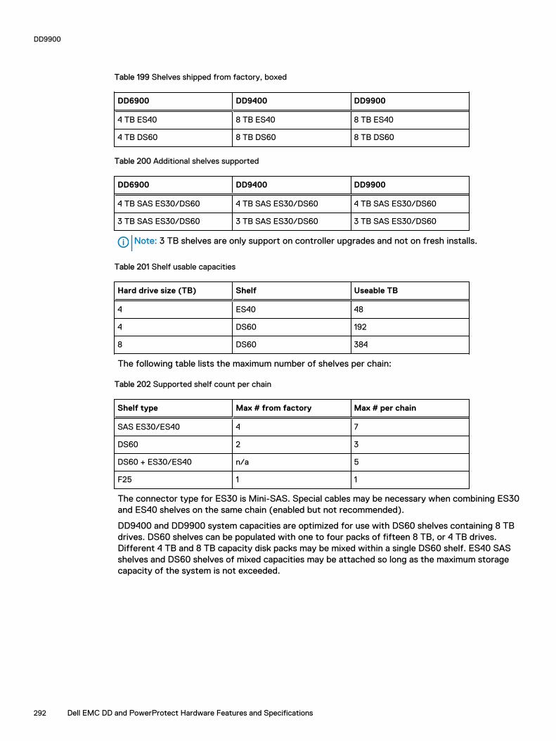
Table 199 Shelves shipped from factory, boxed
DD6900 DD9400 DD9900
4 TB ES40 8 TB ES40 8 TB ES40
4 TB DS60 8 TB DS60 8 TB DS60
Table 200 Additional shelves supported
DD6900 DD9400 DD9900
4 TB SAS ES30/DS60 4 TB SAS ES30/DS60 4 TB SAS ES30/DS60
3 TB SAS ES30/DS60 3 TB SAS ES30/DS60 3 TB SAS ES30/DS60
Note: 3 TB shelves are only support on controller upgrades and not on fresh installs.
Table 201 Shelf usable capacities
Hard drive size (TB) Shelf Useable TB
4 ES40 48
4 DS60 192
8 DS60 384
The following table lists the maximum number of shelves per chain:
Table 202 Supported shelf count per chain
Shelf type Max # from factory Max # per chain
SAS ES30/ES40 4 7
DS60 2 3
DS60 + ES30/ES40 n/a 5
F25 1 1
The connector type for ES30 is Mini-SAS. Special cables may be necessary when combining ES30and ES40 shelves on the same chain (enabled but not recommended).
DD9400 and DD9900 system capacities are optimized for use with DS60 shelves containing 8 TBdrives. DS60 shelves can be populated with one to four packs of fifteen 8 TB, or 4 TB drives.Different 4 TB and 8 TB capacity disk packs may be mixed within a single DS60 shelf. ES40 SASshelves and DS60 shelves of mixed capacities may be attached so long as the maximum storagecapacity of the system is not exceeded.
DD9900
292 Dell EMC DD and PowerProtect Hardware Features and Specifications

CHAPTER 13
DS60
This chapter contains the following topics:
l DS60 overview.................................................................................................................... 294l DS60 site requirements.......................................................................................................294l DS60 hardware specifications.............................................................................................295l DS60 front panel ................................................................................................................ 296l Back panel........................................................................................................................... 297l Disk enclosure interior ........................................................................................................ 297l Expansion shelf cables......................................................................................................... 301l Ports................................................................................................................................... 302
Dell EMC DD and PowerProtect Hardware Features and Specifications 293
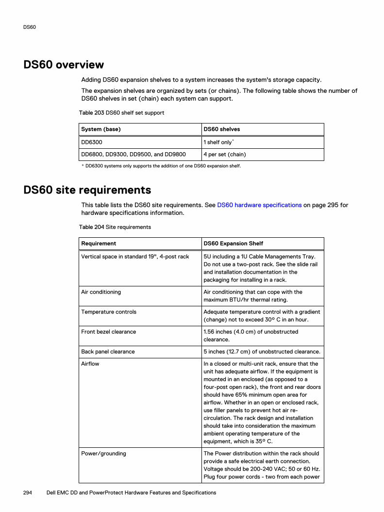
DS60 overviewAdding DS60 expansion shelves to a system increases the system's storage capacity.
The expansion shelves are organized by sets (or chains). The following table shows the number ofDS60 shelves in set (chain) each system can support.
Table 203 DS60 shelf set support
System (base) DS60 shelves
DD6300 1 shelf only*
DD6800, DD9300, DD9500, and DD9800 4 per set (chain)
* DD6300 systems only supports the addition of one DS60 expansion shelf.
DS60 site requirementsThis table lists the DS60 site requirements. See DS60 hardware specifications on page 295 forhardware specifications information.
Table 204 Site requirements
Requirement DS60 Expansion Shelf
Vertical space in standard 19", 4-post rack 5U including a 1U Cable Managements Tray.Do not use a two-post rack. See the slide railand installation documentation in thepackaging for installing in a rack.
Air conditioning Air conditioning that can cope with themaximum BTU/hr thermal rating.
Temperature controls Adequate temperature control with a gradient(change) not to exceed 30° C in an hour.
Front bezel clearance 1.56 inches (4.0 cm) of unobstructedclearance.
Back panel clearance 5 inches (12.7 cm) of unobstructed clearance.
Airflow In a closed or multi-unit rack, ensure that theunit has adequate airflow. If the equipment ismounted in an enclosed (as opposed to afour-post open rack), the front and rear doorsshould have 65% minimum open area forairflow. Whether in an open or enclosed rack,use filler panels to prevent hot air re-circulation. The rack design and installationshould take into consideration the maximumambient operating temperature of theequipment, which is 35° C.
Power/grounding The Power distribution within the rack shouldprovide a safe electrical earth connection.Voltage should be 200-240 VAC; 50 or 60 Hz.Plug four power cords - two from each power
DS60
294 Dell EMC DD and PowerProtect Hardware Features and Specifications
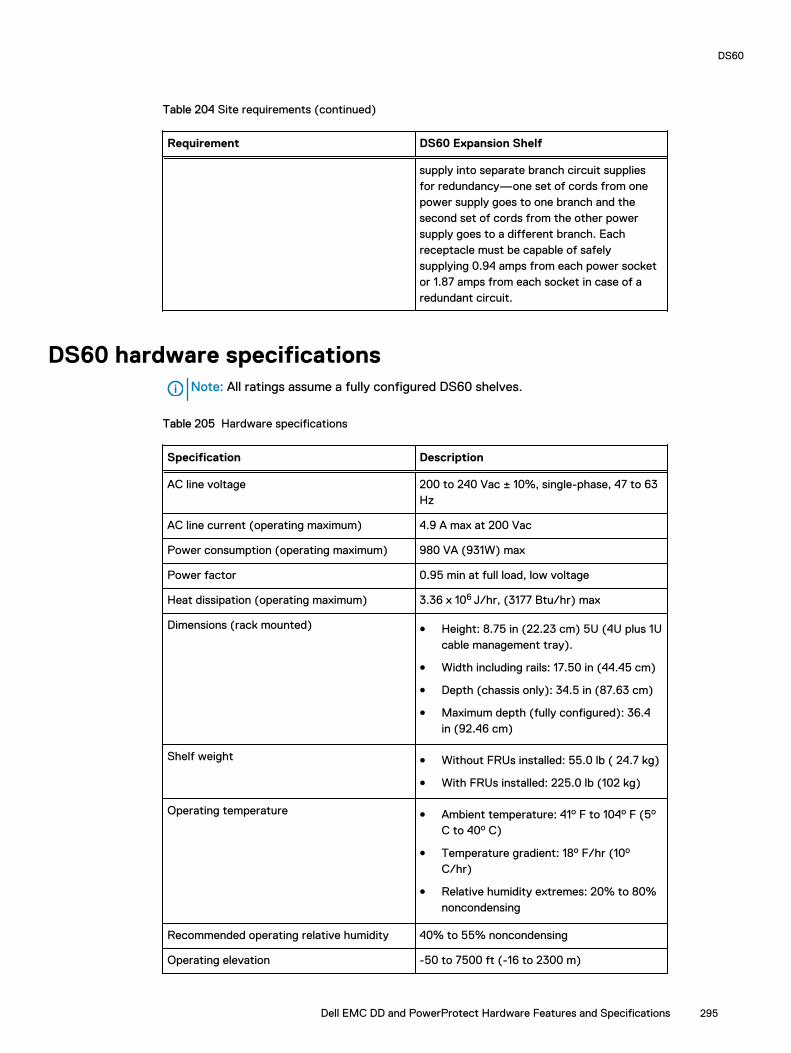
Table 204 Site requirements (continued)
Requirement DS60 Expansion Shelf
supply into separate branch circuit suppliesfor redundancy—one set of cords from onepower supply goes to one branch and thesecond set of cords from the other powersupply goes to a different branch. Eachreceptacle must be capable of safelysupplying 0.94 amps from each power socketor 1.87 amps from each socket in case of aredundant circuit.
DS60 hardware specificationsNote: All ratings assume a fully configured DS60 shelves.
Table 205 Hardware specifications
Specification Description
AC line voltage 200 to 240 Vac ± 10%, single-phase, 47 to 63Hz
AC line current (operating maximum) 4.9 A max at 200 Vac
Power consumption (operating maximum) 980 VA (931W) max
Power factor 0.95 min at full load, low voltage
Heat dissipation (operating maximum) 3.36 x 10⁶ J/hr, (3177 Btu/hr) max
Dimensions (rack mounted) l Height: 8.75 in (22.23 cm) 5U (4U plus 1Ucable management tray).
l Width including rails: 17.50 in (44.45 cm)
l Depth (chassis only): 34.5 in (87.63 cm)
l Maximum depth (fully configured): 36.4in (92.46 cm)
Shelf weight l Without FRUs installed: 55.0 lb ( 24.7 kg)
l With FRUs installed: 225.0 lb (102 kg)
Operating temperature l Ambient temperature: 41o F to 104o F (5o
C to 40o C)
l Temperature gradient: 18o F/hr (10o
C/hr)
l Relative humidity extremes: 20% to 80%noncondensing
Recommended operating relative humidity 40% to 55% noncondensing
Operating elevation -50 to 7500 ft (-16 to 2300 m)
DS60
Dell EMC DD and PowerProtect Hardware Features and Specifications 295

Table 205 Hardware specifications (continued)
Specification Description
Non-operating (shipping and storage)temperature
l Ambient temperature: -40o F to 149o F(-40o C to 65o F)
l Temperature gradient: 45o F/hr(25oC/hr)
l Relative humidity: 10% to 90%noncondensing
l Elevation: -50 to 35,000 ft (-16 to 10,600m)
DS60 front panelFigure 171 DS60 front panel
Note: The front LEDs are identified inside the red rectangle.
If there is a problem with the enclosure, the enclosure fault light LED (marked with a triangle withan exclamation mark) is amber. When the shelf is powered on and active, the disk enclosure powerLED (marked with a circle with a vertical line) is blue.
Table 206 LED status lights
Light Quantity Color Meaning
Disk Enclosure Power 1 Blue Power to enclosure ison.
Disk Enclosure Fault 1 Amber On when any faultcondition exists; if thefault is not obviousfrom a disk or fanmodule light, look atthe back of the diskenclosure.
Note: The individual disk LEDs are only visible when the disk enclosure is opened to verify thedisks inside.
DS60
296 Dell EMC DD and PowerProtect Hardware Features and Specifications

For part replacement information, refer to the DS60 Expansion Shelf Installation and FRUReplacement Guide.
Back panelThe back panel has two dual power supplies and two LCCs (Link Controller Cards).
Figure 172 DS60 back panel
Each controller has 4 SAS ports (laid out as 2 pairs). Standard systems and systems with thelicensed HA feature only use ports 0 and 2 on each controller. Ports 1 and 3 typically have a plasticplug blocking the unused ports to make inserting a cable into the correct ports easier.
Table 207 Status lights visible from rear of disk enclosure
Light Quantity Color Meaning
Controllerpower
1 per controller Green On when the Controller is powered on.
Controller fault 1 per controller Amber On when either the Controller or a SASconnection is faulty. On during power-onself test.
Link active 4 per controller Blue On when the host connection is active.
Power supplyinput voltage
1 per powersupply
Green Input power green when it is working.
Power supplyfault*
1 per powersupply
Amber l On when the power supply is faulty oris not receiving AC line voltage.
l Flashing when either a multiple bloweror ambient over temperature conditionhas shut off DC power to the system.
The DS60 continues to run with a single power supply and two fans (out of the three fans).
Disk enclosure interiorThe disks are visible when the DS60 is pulled out of the rack and the top cover is removed fromthe chassis. There are also three fans in the front of the disk enclosure and each fan has a faultLED.
DS60
Dell EMC DD and PowerProtect Hardware Features and Specifications 297

Each disk in the enclosure has two LEDs. The active LED glows blue when the disk is functional.The disk fault LED glows amber when the disk has failed.
Note: The individual disk and fan LEDs are only visible when the disk enclosure is opened toverify the disks inside.
Figure 173 Fans and disk drives inside the disk enclosure
Table 208 LED status lights
Light Quantity Color Meaning
Disk ActiveNote: Only visibleafter the diskenclosure isopened.
1 per disk module Blue l No LED when theslot is empty orhas a fillermodule. Also, offwhen the disk ispowered down bycommand; forexample, theresult of atemperaturefault.
l Fast blinkingwhen the SASdrive is poweredup but notspinning; this is anormal part of thespin-upsequence,occurring duringthe spin-updelays of a slot.
DS60
298 Dell EMC DD and PowerProtect Hardware Features and Specifications

Table 208 LED status lights (continued)
Light Quantity Color Meaning
l On when thedrive has powerbut is not handingany I/O activity(the ready state).
l Disk and fanlights are onlyavailable whenenclosure isremoved from thechassis.
l Slow blinkingwhen the drive isspinning andhandling I/Oactivity.
Disk FaultNote: Only visibleafter the diskenclosure isopened.
1 per disk module Amber On when the diskmodule is faulty, or asan indication toreplace the drive.
Fan fault 1 per fan module Amber On when the fanmodule is faulty, or asan indication toreplace the fan.
The DD OS software manages the drives in packs (groups) of 15. A top down view of the chassisshows that the disks are arranged in four packs (groups) of 15 drives. The packs are color coded—pack 1 purple, pack 2 is yellow, pack 3 is green, and pack 4 is pink. A pack must have the same sizedrives. Pack 1 is shown within the red rectangle.
DS60
Dell EMC DD and PowerProtect Hardware Features and Specifications 299

Figure 174 Drives as packs
The next table shows how the drives are distributed by packs (groups) and numbered physically.The bottom of the table represents the front of the shelf
Table 209 Physical drives
Rows Pack 1 Pack 2 Pack 3 Pack 4
E 0-2 3-5 6-8 9-11
D 0-2 3-5 6-8 9-11
C 0-2 3-5 6-8 9-11
B 0-2 3-5 6-8 9-11
A 0-2 3-5 6-8 9-11
Although the disk numbers are physically 0 to 59, the disks are reported logically by systemsoftware commands in two ways:
l A range from 1 to 60, usually reported with the enclosure number (e.g. 3.37)
l The position matrix A-E (1-12)
For part replacement information, refer to the DS60 Expansion Shelf Installation and FRUReplacement Guide.
DS60
300 Dell EMC DD and PowerProtect Hardware Features and Specifications

Expansion shelf cablesExpansion shelves are connected to each other and to the controller with qualified cables. Theexpansion shelf can be connected to supported systems only by using SAS (serial-attached SCSI)cables. A shelf with qualified disks can be added as an expansion shelf if there are complete drivepacks (15 in a pack) in the correct position.
Note: Shelves for other Dell EMC product lines look identical. Check the product numberswhen unpacking.
DS60 cables
The DS60 shelves use cables with HD-mini-SAS connectors at both ends to connect the shelves tothe controllers that have SAS I/O modules.
The DS60 connector is referred as the HD-mini-SAS connector and is same as the I/O moduleconnectors. These cables are available in 3M, 4M, and 5M lengths.
Use the appropriate length for the connection you are making:
l Use the 3-meter cable in the same rack either to connect to a controller or shelf to adjacentshelf.
l Use a 3-meter, 4-meter, or 5-meter cable when a DS60 is in another rack.
Figure 175 HD-mini-SAS connector
Table 210 HD-mini-SAS to mini-SAS cable part numbers
Cable Part Number Cable Length
038-004-380-01 3M(118 in.)
038-000-212-00 4M (158 in.)
038-000-214-00 5M (196 in.)
Special cables must be used when attaching an ES30 to a chain with a DS60. Specifically, oneHOST (circle) connection and one EXPANSION (diamond) cables are connected between theES30 LCC and the DS60 LCC connection. Since this is not a common situation, only twoexpansion cable lengths are available.
DS60
Dell EMC DD and PowerProtect Hardware Features and Specifications 301

Table 211 HD-mini-SAS to ES30 host and ES30 expansion port cable part numbers
Cable Part Number Cable Type Cable Length
038-003-810 Host 2M (78 in.)
038-003-813 Host 5M (196 in.)
038-004-108 Expansion 2M (78 in.)
038-004-111 Expansion 5M (196 in.)
The cable connectors must be secured with their latch assembly.
PortsDepending on the model, a system has two to four quad-port SAS IO modules installed. The DS60shelf has two controllers, and each DS60 controller has four ports, labeled 0, 1, 2, and 3 (right toleft).
DS60
302 Dell EMC DD and PowerProtect Hardware Features and Specifications

CHAPTER 14
ES30
This chapter contains the following topics:
l ES30 overview.................................................................................................................... 304l Site requirements................................................................................................................304l ES30 hardware specifications............................................................................................. 305l Front panel..........................................................................................................................306l Back panel........................................................................................................................... 307l Ports....................................................................................................................................310
Dell EMC DD and PowerProtect Hardware Features and Specifications 303

ES30 overviewAdding ES30 expansion shelves to a system increases the system's storage capacity.
The expansion shelves are organized by sets (or chains). The following table shows the number ofES30 shelves than can be in a set.
Table 212 ES30 shelves in a set
Configuration ES30 shelves
Base systems 1–4
Extended Retention software option 1–7
For redundancy, a shelf set is usually connected to two separate SAS I/O modules or HBA cardson the controller, and all of the shelves within a set are connected to each other via dual paths.
Site requirementsThis table lists the site requirements. See ES30 hardware specifications on page 305 for hardwarespecifications information.
Table 213 site requirements
Requirement expansion shelf
Vertical Space inStandard 19", 4-postRack
3U. Do not use a two-post rack. See the slide rail and installationdocumentation in the packaging for installing in a rack.
Air Conditioning Air conditioning that can cope with the maximum BTU/hr thermalrating.
TemperatureControls
Adequate temperature control with a gradient (change) not to exceed30° C in an hour.
Front BezelClearance
1.56 inches (4.0 cm) of unobstructed clearance.
Back PanelClearance
5 inches (12.7 cm) of unobstructed clearance.
Airflow In a closed or multi-unit rack, ensure that the unit has adequate airflow.If the equipment is mounted in an enclosed (as opposed to a four-postopen rack), the front and rear doors should have 65% minimum openarea for airflow. Whether in an open or enclosed rack, use filler panelsto prevent hot air recirculation. The rack design and installation shouldtake into consideration the maximum ambient operating temperature ofthe equipment, which is 35° C.
Power/ Grounding Two single-phase AC power outlets with an earth ground conductor(safety ground). A safe electrical earth connection must be provided toeach power cord. Voltage should be 100-120 VAC or 200-240 VAC; 50or 60 Hz. Use only with branch circuits protected by a minimum 15Aovercurrent protector. Plug the two power cords into separate branchcircuit supplies for redundancy.
ES30
304 Dell EMC DD and PowerProtect Hardware Features and Specifications

ES30 hardware specificationsNote: All ratings assume a fully configured ES30.
Table 214 ES30 hardware specifications
Specification Description
AC line voltage 100 to 240 Vac ± 10%, single-phase, 47 to 63Hz
AC line current (operating maximum) 2.8 A max at 100 Vac, 1.4 A max at 200 Vac
Power consumption (operating maximum) 280 VA (235 W) max
Power factor 0.98 min at full load, low voltage
Heat dissipation (operating maximum) 8.46 x 10⁵ J/hr, (800 Btu/hr) max
Dimensions (rack mounted, with bezel) l Width: 17.62" (45 cm) Depth: 14”(35.56cm)
l Height: 5.25” (13.34cm) 3 RU
Maximum Weight 68 lbs (30.8 kg)
Table 215 System operating environment
Operating Temperature l Ambient temperature: 10o
C to 35o C (50o F to 95o
F)
l Temperature gradient:10o C/hr (180o F/hr)
l Relative humidityextremes: 20% to 80%noncondensing
Recommended OperatingRelative Humidity
40% to 55% noncondensing
Operating Humidity l Ambient temperature:-40o C to 65o C (-40o Fto 149o F)
l Temperature gradient:25o C/hr (45oF/hr)
l Relative humidity: 10% to90% noncondensing
Non-operating Temperature -40° to +149° F (-40° to+65° C)
Operating Acoustic Noise Sound power, LWAd: 7.4 bels.Sound pressure, LpAm: 58dB. (Declared noise emissionper ISO 9296.)
ES30
Dell EMC DD and PowerProtect Hardware Features and Specifications 305

Table 215 System operating environment (continued)
Expansion Shelves: Max 58dB LpA average measured atbystander positions
Front panelAfter you unlock and remove the snap-on bezel on the front panel, the 15 disks are visible. Disknumbers, as reported by system commands, range from 1 to 15. When facing the front panel, Disk 1is located in the leftmost slot in the enclosure and Disk 15 in the rightmost slot.
Figure 176 ES30 front panel (bezel removed)
Note: The flanges or sheet metal on the ES30 show 0 to 14 but the software will refer to thelogical numbering of 1 to 15.
Each disk in the enclosure has two LEDs. The disk’s active LED glows green when the disk isfunctional. The disk fault LED glows amber when the disk has failed.
If there is a problem with the enclosure, the enclosure fault light is amber. The disk enclosurepower light should be on (blue) when the shelf is powered on.
When replacing disks, a good practice is to run this command:
disk beacon <enclosure-id>.<disk-id>
Note: The disk beacon command causes the LED that signals normal operation to flash onthe target disk. Enter Ctrl-C to stop the flash. You can also use the enclosure beaconcommand to check the LED to blink on every disk.
Figure 177 Front panel LEDs
ES30
306 Dell EMC DD and PowerProtect Hardware Features and Specifications

1. Disk enclosure fault light2. Disk enclosure power light3. Disk active light4. Disk fault light
Table 216 Status lights visible from front of disk enclosure
Light Quantity Color Meaning
Disk enclosurefault light
1 Amber On when any fault condition exists; if the faultis not obvious from a disk module light, look atthe back of the disk enclosure.
Disk enclosurepower light
1 Blue Power to enclosure is on.
Disk active light 1 per diskmodule
Green No LED when the slot is empty or has a fillermodule. Also, off when the disk is powereddown by command; for example, the result ofa temperature fault.Fast blinking when the SATA/SAS drive ispowered up but not spinning; this is a normalpart of the spin-up sequence, occurringduring the spin-up delays of a slot.
On when the drive has power but is nothanding any I/O activity (the ready state.
Slow blinking when the drive is spinning andhandling I/O activity.
Disk fault light 1 per diskmodule
Amber On when the disk module is faulty, or as anindication to replace the drive.
Back panelFor redundancy, the shelf has two identical power supply/cooling modules and two identical shelfcontrollers which are placed in reverse order.
Note: When replacing a component, note its orientation before removing it. Insert thereplacement in the same position.
Power supply A and controller A are located at the bottom of the chassis, and power supply B andcontroller B are located at the top of the chassis.
ES30
Dell EMC DD and PowerProtect Hardware Features and Specifications 307
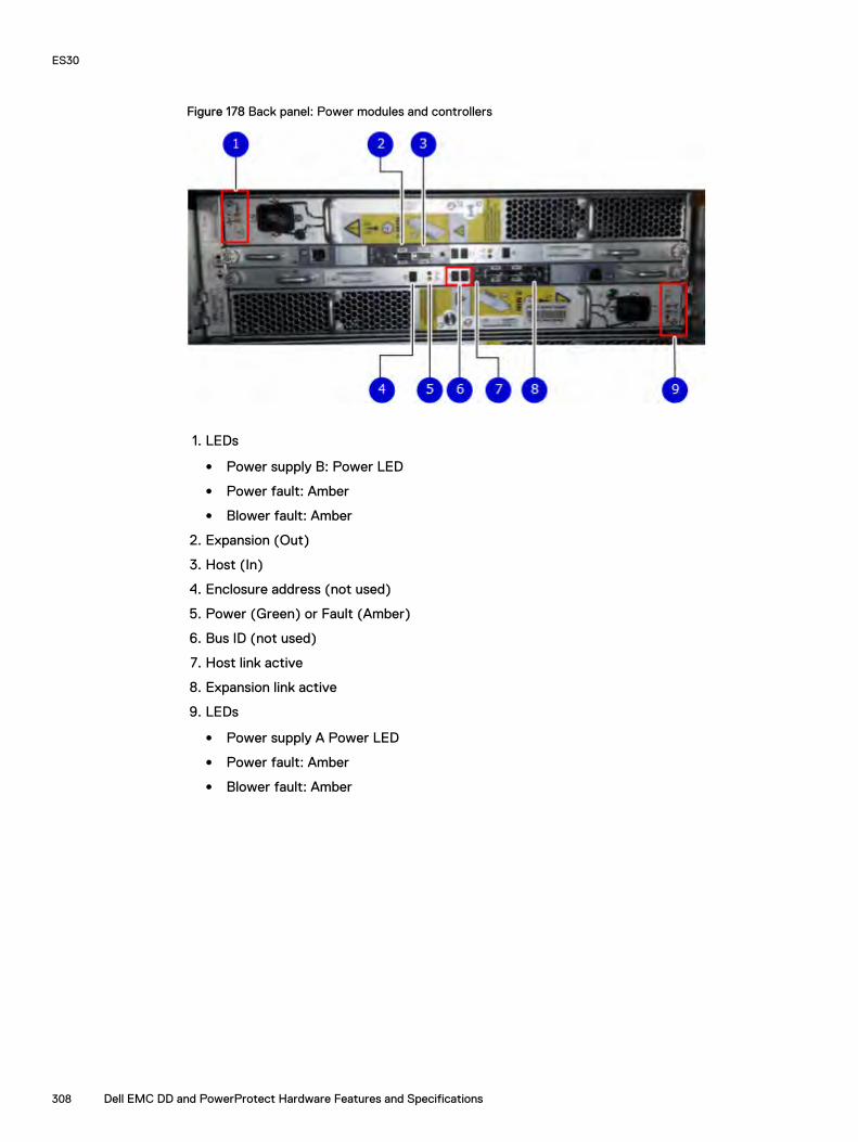
Figure 178 Back panel: Power modules and controllers
1. LEDs
l Power supply B: Power LED
l Power fault: Amber
l Blower fault: Amber
2. Expansion (Out)
3. Host (In)
4. Enclosure address (not used)
5. Power (Green) or Fault (Amber)
6. Bus ID (not used)
7. Host link active
8. Expansion link active
9. LEDs
l Power supply A Power LED
l Power fault: Amber
l Blower fault: Amber
ES30
308 Dell EMC DD and PowerProtect Hardware Features and Specifications

Figure 179 Power Supply A LEDs
Each shelf controller has two SAS ports. The port labeled with a circle symbol is the Host port, andthe port labeled with a diamond symbol is the Expansion port. The Expansion ports are located onthe outside, and the Host ports on the inside (reversed controller positions).
Table 217 Status lights visible from rear of disk enclosure
Light Quantity Color Meaning
ControllerPower
1 per Controller Blue or Green On when the Controller is powered on.Blue when host connection is active at thenormal speed for DD990, DD2500,DD4200, DD4500, , , DD7200, , DD9500,and systems.
Green when host connection is slow forthose systems or at normal speed for allother systems.
Controller Fault 1 per Controller Amber On when either the Controller or a SASconnection is faulty. On during power-onself-test
Host Link Active 1 per Controller Blue On when the host connection is active.
Expansion LinkActive
1 per Controller Blue On when the expansion connection isactive.
Power SupplyActive
1 per powersupply
Green On when the power supply is operating.
Power SupplyFault*
1 per powersupply
Amber On when the power supply is faulty or isnot receiving AC line voltage.Flashing when either a multiple blower orambient over temperature condition hasshut off DC power to the system.
Blower Fault* 1 per powersupply
Amber On when one of the blowers in the powersupply is faulty.
ES30
Dell EMC DD and PowerProtect Hardware Features and Specifications 309

*The ES30 and continue to run with a single power supply and three of its four blowers. Removinga power/cooling module constitutes a multiple blower fault condition, and powers down the shelfunless you replace a module within two minutes.
PortsDepending on the model, a system has one to four dual- or quad-port SAS HBA cards or SAS I/Omodules installed. The ES30 shelf has two controllers (B located above A). Each controller has twoports, a host and an expansion port.
ES30
310 Dell EMC DD and PowerProtect Hardware Features and Specifications

CHAPTER 15
ES40
This chapter contains the following topics:
l ES40 overview..................................................................................................................... 312l Dimensions and weights.......................................................................................................312l Power requiremements........................................................................................................ 312l DAE-to-DAE copper cabling.................................................................................................314l Product service tag..............................................................................................................314l System operating limits........................................................................................................315
Dell EMC DD and PowerProtect Hardware Features and Specifications 311

ES40 overviewAdding ES40 expansion shelves to a system increases the system's storage capacity.
The expansion shelves are organized by sets (or chains). The following table shows the number ofES40 shelves than can be in a set.
Table 218 ES40 shelves in a set
System (base) ES40 shelves
DD6900 1–7
DD9400 1–7
DD9900 1–7
For redundancy, a shelf set is usually connected to two separate SAS I/O modules or HBA cardson the controller, and all of the shelves within a set are connected to each other via dual paths.
Dimensions and weights
Table 219 Dimensions and weight
Dimensions Vertical size Weight (see note)
Height: 5.25 in (13.34 cm)
3 NEMA units 68 lb (30.8 kg) with 15 disksWidth: 17.62 in (44.75 cm)
Depth: 14.0 in (35.6 cm)
Note: The weight does not include mounting rails. Allow 5-10 lb (2.3-4.5 kg) for a rail set. Theweights listed in this table do not describe enclosures with solid state disk drives with Flashmemory (called Flash or SSD drives). These Flash drive modules weigh 20.8 ounces (1.3 lb)each.
Power requiremements
The input current, power (VA), and dissipation per enclosure listed in this document are based onmeasurements of fully configured enclosures under worst-case operating conditions. Use theoperating maximum values to plan the configuration of your storage system. These valuesrepresent either:
l the values for a single power supply line cord, or
l the sum of the values shared by the line cords of the combined power supplies in the sameenclosure, with the division between the line cords and supplies at the current sharing ratio(approximately 50% each).
A failure of one of the combined power supplies per enclosure results in the remaining powersupply supporting the full load. You must use a rackmount cabinet or rack with appropriate powerdistribution, and have main branch AC distribution that can handle these values for each enclosurein the cabinet.
ES40
312 Dell EMC DD and PowerProtect Hardware Features and Specifications

Table 220 AC power specifications
Requirement Description
AC line voltage 100 to 240V AC ± 10%, single-phase, 47 to 63 Hz
AC line current (operatingmaximum)
2.9 A max at 100V AC
1.6 A max at 200V AC
Power consumption (operatingmaximum)
287 VA (281 W) max at 100V AC
313 VA (277 W) max at 200V AC
Power factor 0.9 min at full load at 100V AC
0.9 min at full load at 200V AC
Heat dissipation (operatingmaximum)
1.01 x 10⁶ J/hr (959 Btu/hr) max at 100V AC
1.01 x 10⁶ J/hr (945 Btu/hr) max at 200V AC
In-rush current 30 A max for ½ line cycle, per line cord at 240V AC
Startup surge current 25 A peak max per line cord, max at any line voltage
AC protection 10 A fuse on each power supply, both Line and Neutral
AC inlet type IEC320-C14 appliance coupler, per power zone
Ride-through time 30 ms min
Current sharing Droop Load Sharing
Note:
l Ratings assume a fully loaded DAE that includes 2 power supplies and 12 worst casedisk drive slot numbers.
l All power figures shown represent max normal operating numbers with the chassisrunning in a normal 20°C to 25°C ambient temperature environment. The chassispower numbers given may increase when running in a higher ambient temperatureenvironment.
l For specific product configuration power numbers, refer to the EMC Power Calculatorlocated on the internet at https://powercalculator.emc.com. The Power Calculatorwill provide the chassis power delta when operating in different ambient temperatureranges and configurations. However, it will only support products with an inputvoltage range of 200-240V ac.
Table 221 DC power specifications
Requirement Description
DC line voltage -39 to -72V DC (nominal -48 or -60 V power systems)
DC line current (operatingmaximum)
7.92 A max at -39V DC
6.43 A max at -48V DC
4.39 A max at -72V DC
Power consumption (operatingmaximum)
309 W max at -39V DC
309 W max at -48V DC
ES40
Dell EMC DD and PowerProtect Hardware Features and Specifications 313

Table 221 DC power specifications (continued)
Requirement Description
316 W max at -72V DC
Heat dissipation (operatingmaximum)
1.11 x 10⁶ J/hr (1054 Btu/hr) max at -39V DC
1.11 x 10⁶ J/hr (1054 Btu/hr) max at -48V DC
1.14 x 10⁶ J/hr (1078 Btu/hr) max at -72V DC
In-rush current 20 A peak per requirements in EN300 132-2 Sect 4.7 limitcurve
DC protection 20 A fuse in each power supply
DC inlet type Positronics PLB3W3M1000
Mating DC connector Positronics PLB3W3F7100A1
Positronics Inc.
http://www.connectpositronic.com
Ride-through time 5 ms min. (test condition: Vin = -40V DC)
Current sharing Droop Load Sharing
Note:
l Ratings assume a fully loaded DAE that includes 2 power supplies and 15 maximumdisk slot numbers.
l All power figures shown represent max normal operating numbers with the chassisrunning in a normal 20°C to 25°C ambient temperature environment. The chassispower numbers given may increase when running in a higher ambient temperatureenvironment.
l The EMC Power Calculator does not support DC chassis.
DAE-to-DAE copper cablingThe expansion port interface to and between DAEs is copper cabling. The 100 Ω cables are keyedat either end, and available in 1- 10-meter lengths.
l DAE-to-DAE cables are SFF 8088 mini-SAS to mini-SAS.
l Keys are defined in the T10–SAS 2.1 specification.
Product service tag
The serial number is seven alphanumeric characters and found on the service tag.
ES40
314 Dell EMC DD and PowerProtect Hardware Features and Specifications

System operating limitsThe ambient temperature specification is measured at the front bezel inlet. The site must have airconditioning of the correct size and placement to maintain the specified ambient temperaturerange and offset the heat dissipation listed below.
Table 222 System operating limits
Requirement Description
Ambient temperature 10°C to 40°C (50°F to 104°F)
Temperature gradient 10°C/hr (18°F/hr)
Relative humidity (extremes) 20% to 80% noncondensing
Relative humidity (recommended) 40% to 55% noncondensing
Elevation -16 to 3,048 m (-50 to 10,000 ft)
Note: The allowable relative humidity level is 20 to 80% noncondensing. However, therecommended operating environment range is 40 to 55%. To minimize the risk ofhardware corrosion and degradation, we recommend lower temperatures and humidity fordata centers with gaseous contamination such as high sulfur content. In general, thehumidity fluctuations within the data center should be minimized. We also recommendthat the data center be positively pressured and have air curtains on entry ways toprevent outside air contaminants and humidity from entering the facility. For facilitiesbelow 40% relative humidity, we recommend grounding straps when contacting theequipment to avoid the risk of Electrostatic discharge (ESD), which can harm electronicequipment.
Table 223 System operating limits (meets ASHRAE equipment class A3)
Requirement Description Limit
Recommended rangeoperation
The limits under which equipment willoperate the most reliably while stillachieving reasonably energy-efficientdata center operation.
18°C to 27°C (64.4°F to 80.6°F) at 5.5°C(41.9°F) dew point to 60% relativehumidity and 15°C (59°F) dew point.
Continuous allowablerange operation
Data center economization techniques(i.e. free cooling) may be employed toimprove overall data center efficiency.These techniques may cause equipmentinlet conditions to fall outside therecommended range but still within thecontinuously allowable range. Equipmentmay be operated without any hourlylimitations in this range.
10°C to 35°C (50°F to 95°F) at 20% to80% relative humidity with 21°C (69.8°F)maximum dew point (maximum wet bulbtemperature). De-rate maximum allowabledry bulb temperature at 1°C per 300mabove 950m (1°F per 547 ft above 3117 ft).
Expanded allowable rangeoperation
During certain times of the day or year,equipment inlet conditions may falloutside the continuously allowable rangebut still within the expanded allowablerange. Equipment operation is limited to <10% of annual operating hours in thisrange.
5°C to 10°C (41°F to 50°F) and 35°C and40°C (95°F to 104°F), with no directsunlight on the equipment, at -12°C(10.4°F) dew point and 8% to 85% relativehumidity with 24°C (75.2°F) dew point(maximum wet bulb temperature). Outsidethe continuously allowable range (10°C to
ES40
Dell EMC DD and PowerProtect Hardware Features and Specifications 315

Table 223 System operating limits (meets ASHRAE equipment class A3) (continued)
Requirement Description Limit
35°C / 50°F to 95°F), the system canoperate down to 5°C or up to 40°C (41°Fto 104°F) for a maximum of 10% of itsannual operating hours. For temperaturesbetween 35°C and 40°C (95°F to 104°F),de-rate maximum allowable dry bulbtemperature by 1°C per 175m above 950m(1°F per 319 ft above 3117 ft).
Exceptions to expandedallowable range operation
When operating in the expanded allowabletemperature range, system performanceis guaranteed while the system is awaitingor being serviced.
Due to certain rare operational modes, it isrecommended that service be deferred on60x3.5" Disk Array Enclosures whentemperatures exceed 35°C (95°F).
Temperature gradient 20°C/hr (36°F/hr)
Altitude Max operating 3050m (10,000 ft)
NOTICE For systems mounted in a cabinet, the operating limits listed above must not beexceeded inside the closed cabinet. Equipment mounted directly above or below an enclosuremust not restrict the front-to-rear airflow of the storage system. Cabinet doors must notimpede the front-to-rear airflow. The cabinet must exhaust air at a rate that is equal to orgreater than the sum of the exhaust rates of all the equipment mounted in the cabinet.
Environmental recoveryIf the system exceeds the maximum ambient temperature by approximately 10°C (18°F), thestorage processors (SPs) in the processor enclosure begin an orderly shutdown that saves cacheddata, and then shut themselves down. Link control cards (LCCs) in each DAE power down theirdisks but remain powered on. If the system detects that the temperature has dropped to anacceptable level, it restores power to the SPs and the LCCs restore power to their disk drives.
ES40
316 Dell EMC DD and PowerProtect Hardware Features and Specifications
CHAPTER 16
FS15
This chapter contains the following topics:
l Overview of FS15 SSD drives...............................................................................................318l Site requirements.................................................................................................................318l FS15 hardware specifications...............................................................................................319l FS15 front panel.................................................................................................................. 320l Back panel...........................................................................................................................322l Status LEDs.........................................................................................................................324
Dell EMC DD and PowerProtect Hardware Features and Specifications 317

Overview of FS15 SSD drivesThe FS15 is an external shelf consisting of a specific number of SSD drives, depending upon thesystem, and are used to cache meta-data.
The SSDs for the FS15 shelf are 800GB 3WPD devices, which have positive performance andlongevity characteristics.
Table 224 Number of SSD drives and model compatibilty
Number of Drives Model
2 DD6300 with HA
5 l DD6800 with HA
l DD9300 with HA
8 l DD9300 with HA
l DD9500 - with or without HA
15 DD9500 - with or without HA
Note: Unused drive slots have drive fillers to improve airflow.
There are also upgrade kits available to add more SSDs if a system is expanded to have additionalmemory.
Upgrade Pack Use
3 Drive Upgrade Pack To create a 5 drive shelf from originally a 2drive shelf or an 8 drive shelf from originally a5 drive shelf
7 Drive Upgrade Pack To create a 15 drive shelf from an 8 drive shelf
Site requirementsThis table lists the FS15 site requirements.
Table 225 FS15 site requirements
Requirement FS15 shelf
Vertical Space inStandard 19", 4-postRack
3U. Do not use a two-post rack. See the slide rail and installationdocumentation in the packaging for installing in a rack.
Air Conditioning Air conditioning that can cope with the maximum BTU/hr thermalrating.
TemperatureControls
Adequate temperature control with a gradient (change) not to exceed30° C in an hour.
Front BezelClearance
1.56 inches (4.0 cm) of unobstructed clearance.
FS15
318 Dell EMC DD and PowerProtect Hardware Features and Specifications

Table 225 FS15 site requirements (continued)
Requirement FS15 shelf
Back PanelClearance
5 inches (12.7 cm) of unobstructed clearance.
Airflow In a closed or multi-unit rack, ensure that the unit has adequate airflow.If the equipment is mounted in an enclosed (as opposed to a four-postopen rack), the front and rear doors should have 65% minimum openarea for airflow. Whether in an open or enclosed rack, use filler panelsto prevent hot air recirculation. The rack design and installation shouldtake into consideration the maximum ambient operating temperature ofthe equipment, which is 35° C.
Power/ Grounding Two single-phase AC power outlets with an earth ground conductor(safety ground). A safe electrical earth connection must be provided toeach power cord. Voltage should be 100-120 VAC or 200-240 VAC; 50or 60 Hz. Use only with branch circuits protected by a minimum 15Aovercurrent protector. Plug the two power cords into separate branchcircuit supplies for redundancy.
FS15 hardware specificationsNote: All ratings assume a fully configured FS15.
Table 226 FS15 hardware specifications
Specification Description
AC line voltage 100 to 240 Vac ± 10%, single-phase, 47 to 63Hz
AC line current (operating maximum) 2.8 A max at 100 Vac, 1.4 A max at 200 Vac
Power consumption (operating maximum) 280 VA (235 W) max
Power factor 0.98 min at full load, low voltage
Heat dissipation (operating maximum) 8.46 x 10⁵ J/hr, (800 Btu/hr) max
Dimensions (rack mounted, with bezel) l Width: 17.62" (45 cm) Depth: 14”(35.56cm)
l Height: 5.25” (13.34cm) 3 RU
Maximum Weight 68 lbs (30.8 kg)
Operating Temperature l Ambient temperature: 10o C to 35o C (50o
F to 95o F)
l Temperature gradient: 10o C/hr (180o
F/hr)
l Relative humidity extremes: 20% to 80%noncondensing
Recommended Operating Relative Humidity 40% to 55% noncondensing
FS15
Dell EMC DD and PowerProtect Hardware Features and Specifications 319

Table 226 FS15 hardware specifications (continued)
Specification Description
Non-Operating Temperature l Ambient temperature: -40o C to 65o C(-40o F to 149o F)
l Temperature gradient: 25o C/hr(45oF/hr)
l Relative humidity: 10% to 90%noncondensing
FS15 front panelAfter you unlock and remove the snap-on bezel on the front panel, the 15 disks are visible. Disknumbers, as reported by system commands, range from 1 to 15. When facing the front panel, Disk 1is located in the leftmost slot in the enclosure and Disk 15 in the rightmost slot.
Figure 180 FS15 front panel (bezel removed)
Note: The flanges or sheet metal on the FS15 show 0 to 14 but the software will refer to thelogical numbering of 1 to 15.
Each disk in the enclosure has two LEDs. The disk’s active LED glows green when the disk isfunctional. The disk fault LED glows amber when the disk has failed.
If there is a problem with the enclosure, the enclosure fault light is amber. The disk enclosurepower light should be on (blue) when the shelf is powered on.
When replacing FS15 disks, a good practice is to run this command:
disk beacon <enclosure-id>.<disk-id>
Note: The disk beacon command causes the LED that signals normal operation to flash onthe target disk. Enter Ctrl-C to stop the flash. You can also use the enclosure beaconcommand to check the LED to blink on every disk.
FS15
320 Dell EMC DD and PowerProtect Hardware Features and Specifications
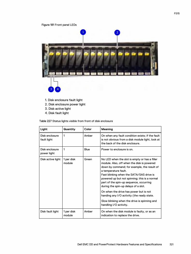
Figure 181 Front panel LEDs
1. Disk enclosure fault light2. Disk enclosure power light3. Disk active light4. Disk fault light
Table 227 Status lights visible from front of disk enclosure
Light Quantity Color Meaning
Disk enclosurefault light
1 Amber On when any fault condition exists; if the faultis not obvious from a disk module light, look atthe back of the disk enclosure.
Disk enclosurepower light
1 Blue Power to enclosure is on.
Disk active light 1 per diskmodule
Green No LED when the slot is empty or has a fillermodule. Also, off when the disk is powereddown by command; for example, the result ofa temperature fault.Fast blinking when the SATA/SAS drive ispowered up but not spinning; this is a normalpart of the spin-up sequence, occurringduring the spin-up delays of a slot.
On when the drive has power but is nothanding any I/O activity (the ready state.
Slow blinking when the drive is spinning andhandling I/O activity.
Disk fault light 1 per diskmodule
Amber On when the disk module is faulty, or as anindication to replace the drive.
FS15
Dell EMC DD and PowerProtect Hardware Features and Specifications 321
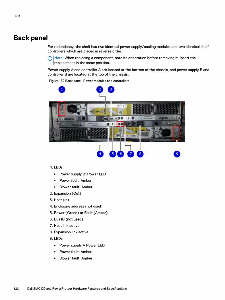
Back panelFor redundancy, the shelf has two identical power supply/cooling modules and two identical shelfcontrollers which are placed in reverse order.
Note: When replacing a component, note its orientation before removing it. Insert thereplacement in the same position.
Power supply A and controller A are located at the bottom of the chassis, and power supply B andcontroller B are located at the top of the chassis.
Figure 182 Back panel: Power modules and controllers
1. LEDs
l Power supply B: Power LED
l Power fault: Amber
l Blower fault: Amber
2. Expansion (Out)
3. Host (In)
4. Enclosure address (not used)
5. Power (Green) or Fault (Amber)
6. Bus ID (not used)
7. Host link active
8. Expansion link active
9. LEDs
l Power supply A Power LED
l Power fault: Amber
l Blower fault: Amber
FS15
322 Dell EMC DD and PowerProtect Hardware Features and Specifications

Figure 183 Power Supply A LEDs
Each shelf controller has two SAS ports. The port labeled with a circle symbol is the Host port, andthe port labeled with a diamond symbol is the Expansion port. The Expansion ports are located onthe outside, and the Host ports on the inside (reversed controller positions).
Table 228 Status lights visible from rear of disk enclosure
Light Quantity Color Meaning
ControllerPower
1 per Controller Blue or Green On when the Controller is powered on.Blue when host connection is active at thenormal speed for DD990, DD2500,DD4200, DD4500, , , DD7200, , DD9500,and systems.
Green when host connection is slow forthose systems or at normal speed for allother systems.
Controller Fault 1 per Controller Amber On when either the Controller or a SASconnection is faulty. On during power-onself-test
Host Link Active 1 per Controller Blue On when the host connection is active.
Expansion LinkActive
1 per Controller Blue On when the expansion connection isactive.
Power SupplyActive
1 per powersupply
Green On when the power supply is operating.
Power SupplyFault*
1 per powersupply
Amber On when the power supply is faulty or isnot receiving AC line voltage.Flashing when either a multiple blower orambient over temperature condition hasshut off DC power to the system.
Blower Fault* 1 per powersupply
Amber On when one of the blowers in the powersupply is faulty.
FS15
Dell EMC DD and PowerProtect Hardware Features and Specifications 323

*The ES30 and continue to run with a single power supply and three of its four blowers. Removinga power/cooling module constitutes a multiple blower fault condition, and powers down the shelfunless you replace a module within two minutes.
Status LEDsVerify the status by checking the LEDs. Controller B is located above Controller A in the center ofthe rear panel. The power supply/cooling units are above and below the controllers.
Facing the back panel of the FS15, the Expander ports are the outer of the two ports; the Hostports are the inner of the two ports. The ports are identified by symbols on the rear panel: a circlesymbol indicates a Host port; a diamond symbol indicates an Expander port.
Figure 184 Rear panel overview
Table 229 Status LEDs
Light Quantity Color Meaning
Controller power 1 per controller Green On when thecontroller is poweredon
Controller failure 1 per controller Amber On when either thecontroller or a SASconnection has failed.On during a power-onself test.
Host link active 1 per controller Blue On when the hostconnection is active
Expansion link active 1 per controller Blue On when theexpansion host isactive
FS15
324 Dell EMC DD and PowerProtect Hardware Features and Specifications

CHAPTER 17
FS25
This chapter contains the following topics:
l Overview of FS25 SSD drives............................................................................................. 326l Dimensions and weight........................................................................................................326l Power requirements............................................................................................................ 326l DAE-to-DAE copper cabling................................................................................................ 328l Product service tag............................................................................................................. 328l Air quality requirements.......................................................................................................328l Shock and Vibration............................................................................................................ 329l System operating limits........................................................................................................331l Shipping and storage requirements..................................................................................... 332
Dell EMC DD and PowerProtect Hardware Features and Specifications 325

Overview of FS25 SSD drivesThe FS25 is an external shelf consisting of a specific number of SSD drives, depending upon thesystem, and are used to cache meta-data.
Table 230 Number of SSD drives and model compatibilty
Number of Drives Model
2 DD6900 only with HA
5 DD9400 only with HA
10 DD9900
Note: Unused drive slots have drive fillers to improve airflow.
Dimensions and weight
Table 231 Dimensions and weight
Dimensions Vertical size Weight (see note)
Height: 3.40 in (8.64 cm)
2 NEMA units44.61 lb (20.23 kg) with 25disks
Width: 17.50 in (44.45 cm)
Depth: 14.0 in (35.56 cm)
Note: The weight does not include mounting rails. Allow 5-10 lb (2.3-4.5 kg) for a rail set. Theweights listed in this table do not describe enclosures with solid state disk drives with Flashmemory (called Flash or SSD drives). These Flash drive modules weigh 20.8 ounces (1.3 lb)each.
Power requirementsThe input current, power (VA), and heat dissipation per enclosure listed in this document arebased on measurements of fully configured enclosures under worst-case operating conditions. Usethe operating maximum values to plan the configuration of your storage system. These valuesrepresent either:
l values for a single power supply line cord, or
l the sum of the values shared by the line cords of the combined power supplies in the sameenclosure, with the division between the line cords and supplies at the current sharing ratio(approximately 50% each).
A failure of one of the combined power supplies per enclosure results in the remaining powersupply supporting the full load. You must use a rackmount cabinet or rack with appropriate powerdistribution, and have main branch AC distribution that can handle these values for each enclosurein the cabinet.
FS25
326 Dell EMC DD and PowerProtect Hardware Features and Specifications

Table 232 AC power specifications
Requirement Description
AC line voltage 100 to 240V AC ± 10%, single-phase, 47 to 63 Hz
AC line current (operatingmaximum)
4.5 A max at 100V AC
2.4 A max at 200V AC
Power consumption (operatingmaximum)
453 VA (432 W) max, at 100V AC
585 VA (427 W) max, at 200V AC
Power factor 0.95 min at full load, @ 100V AC
0.95 min at full load, @ 200Vac
Heat dissipation (normal operatingmaximum)
1.56 x 10⁶ J/hr. (1,474 Btu/hr.) max @ 100V AC
1.54 x 10⁶ J/hr, (1,457 Btu/hr) max @ 200Vac
In-rush current 30 Apk "cold" per line cord at any line voltage
Startup surge current 40 Apk "hot" per line cord, at any line voltage
AC protection 15 A fuse on each power supply, single line
AC inlet type IEC320-C14 appliance coupler, per power zone
Ride-through time 12 ms min
Current sharing ± 5% of full load, between power supplies
Note:
l Ratings assume a fully loaded DAE that includes 2 power supplies and 25 worst casedisk drive slot numbers.
l All power figures shown represent max normal operating numbers with the chassisrunning in a normal 20°C to 25°C ambient temperature environment. The chassispower numbers given may increase when running in a higher ambient temperatureenvironment.
l For specific product configuration power numbers, refer to the EMC Power Calculatorlocated on the internet at https://powercalculator.emc.com. The Power Calculatorwill provide the chassis power delta when operating in different ambient temperatureranges and configurations. However, it will only support products with an inputvoltage range of 200-240V ac.
Table 233 DC power specifications
Requirement Description
DC line voltage -39 to -72V DC (nominal -48 or -60 V power systems)
DC line current (operatingmaximum)
11.0 A max at -39V DC
9.10 A max at -48V DC
6.20 A max at -72V DC
Power consumption (operatingmaximum)
428 W max at -39V DC
437 W max at -48V DC
FS25
Dell EMC DD and PowerProtect Hardware Features and Specifications 327

Table 233 DC power specifications (continued)
Requirement Description
448 W max at -72V DC
Heat dissipation (operatingmaximum)
1.54 x 10⁶ J/hr (1460 Btu/hr) max at -39V DC
1.57 x 10⁶ J/hr (1491 Btu/hr) max at -48V DC
1.61 x 10⁶ J/hr (1529 Btu/hr) max at -72V DC
In-rush current 40 A peak per requirements in EN300 132-2 Sect 4.7 limitcurve
DC protection 50 A fuse in each power supply
DC inlet type Positronics PLBH3W3M4B0A1/AA
Mating DC connector Positronics PLBH3W3F0000/AA
Positronics Inc.
http://www.connectpositronic.com
Ride-through time 1 ms min. at -50V input
Current sharing ±5% of full load, between power supplies
Note:
l Ratings assume a fully loaded DAE that includes 2 power supplies and 25 maximumdisk slot numbers.
l All power figures shown represent max normal operating numbers with the chassisrunning in a normal 20°C to 25°C ambient temperature environment. The chassispower numbers given may increase when running in a higher ambient temperatureenvironment.
l The EMC Power Calculator does not support DC chassis.
DAE-to-DAE copper cablingThe expansion port interface to and between DAEs is copper cabling. The 100 Ω cables are keyedat either end, and available in 1- 10-meter lengths.
l DAE-to-DAE cables are SFF 8088 mini-SAS to mini-SAS.
l Keys are defined in the T10–SAS 2.1 specification.
Product service tag
The serial number is seven alphanumeric characters and found on the service tag.
Air quality requirementsThe products are designed to be consistent with the requirements of the American Society ofHeating, Refrigeration and Air Conditioning Engineers (ASHRAE) Environmental Standard
FS25
328 Dell EMC DD and PowerProtect Hardware Features and Specifications

Handbook and the most current revision of Thermal Guidelines for Data Processing Environments,Second Edition, ASHRAE 2009b.
Cabinets are best suited for Class 1 datacom environments, which consist of tightly controlledenvironmental parameters, including temperature, dew point, relative humidity and air quality.These facilities house mission-critical equipment and are typically fault-tolerant, including the airconditioners.
The data center should maintain a cleanliness level as identified in ISO 14664-1, class 8 forparticulate dust and pollution control. The air entering the data center should be filtered with aMERV 11 filter or better. The air within the data center should be continuously filtered with aMERV 8 or better filtration system. In addition, efforts should be maintained to prevent conductiveparticles, such as zinc whiskers, from entering the facility.
The allowable relative humidity level is 20 to 80% non condensing, however, the recommendedoperating environment range is 40 to 55%. For data centers with gaseous contamination, such ashigh sulfur content, lower temperatures and humidity are recommended to minimize the risk ofhardware corrosion and degradation. In general, the humidity fluctuations within the data centershould be minimized. It is also recommended that the data center be positively pressured and haveair curtains on entry ways to prevent outside air contaminants and humidity from entering thefacility.
For facilities below 40% relative humidity, it is recommended to use grounding straps whencontacting the equipment to avoid the risk of Electrostatic discharge (ESD), which can harmelectronic equipment.
As part of an ongoing monitoring process for the corrosiveness of the environment, it isrecommended to place copper and silver coupons (per ISA 71.04-1985, Section 6.1 Reactivity), inairstreams representative of those in the data center. The monthly reactivity rate of the couponsshould be less than 300 Angstroms. When monitored reactivity rate is exceeded, the couponshould be analyzed for material species and a corrective mitigation process put in place.
Storage time (unpowered) recommendation: do not exceed 6 consecutive months of unpoweredstorage.
Shock and VibrationProducts have been tested to withstand the shock and random vibration levels. The levels apply toall three axes and should be measured with an accelerometer on the equipment enclosures withinthe cabinet and shall not exceed:
Platform condition Response measurement level
Non operational shock 10 G’s, 7 ms duration
Operational shock 3 G’s, 11 ms duration
Non operational random vibration 0.40 Grms, 5–500 Hz, 30 minutes
Operational random vibration 0.21 Grms, 5–500 Hz, 10 minutes
Systems that are mounted on an approved package have completed transportation testing towithstand the following shock and vibrations in the vertical direction only and shall not exceed:
Packaged system condition Response measurement level
Transportation shock 10 G’s, 12ms duration
Transportation random vibration l 1.15 Grms
FS25
Dell EMC DD and PowerProtect Hardware Features and Specifications 329

Packaged system condition Response measurement level
l 1 hour Frequency range 1–200 Hz
FS25
330 Dell EMC DD and PowerProtect Hardware Features and Specifications

System operating limitsThe ambient temperature specification is measured at the front bezel inlet. The site must have airconditioning of the correct size and placement to maintain the specified ambient temperaturerange and offset the heat dissipation listed below.
Table 234 System operating limits
Requirement Description
Ambient temperature 10°C to 40°C (50°F to 104°F)
Temperature gradient 10°C/hr (18°F/hr)
Relative humidity (extremes) 20% to 80% noncondensing
Relative humidity (recommended) 40% to 55% noncondensing
Elevation -16 to 3,048 m (-50 to 10,000 ft)
Note: The allowable relative humidity level is 20 to 80% noncondensing. However, therecommended operating environment range is 40 to 55%. To minimize the risk ofhardware corrosion and degradation, we recommend lower temperatures and humidity fordata centers with gaseous contamination such as high sulfur content. In general, thehumidity fluctuations within the data center should be minimized. We also recommendthat the data center be positively pressured and have air curtains on entry ways toprevent outside air contaminants and humidity from entering the facility. For facilitiesbelow 40% relative humidity, we recommend grounding straps when contacting theequipment to avoid the risk of Electrostatic discharge (ESD), which can harm electronicequipment.
Table 235 System operating limits (meets ASHRAE equipment class A3)
Requirement Description Limit
Recommended rangeoperation
The limits under which equipment willoperate the most reliably while stillachieving reasonably energy-efficientdata center operation.
18°C to 27°C (64.4°F to 80.6°F) at 5.5°C(41.9°F) dew point to 60% relativehumidity and 15°C (59°F) dew point.
Continuous allowablerange operation
Data center economization techniques(i.e. free cooling) may be employed toimprove overall data center efficiency.These techniques may cause equipmentinlet conditions to fall outside therecommended range but still within thecontinuously allowable range. Equipmentmay be operated without any hourlylimitations in this range.
10°C to 35°C (50°F to 95°F) at 20% to80% relative humidity with 21°C (69.8°F)maximum dew point (maximum wet bulbtemperature). De-rate maximum allowabledry bulb temperature at 1°C per 300mabove 950m (1°F per 547 ft above 3117 ft).
Expanded allowable rangeoperation
During certain times of the day or year,equipment inlet conditions may falloutside the continuously allowable rangebut still within the expanded allowablerange. Equipment operation is limited to <10% of annual operating hours in thisrange.
5°C to 10°C (41°F to 50°F) and 35°C and40°C (95°F to 104°F), with no directsunlight on the equipment, at -12°C(10.4°F) dew point and 8% to 85% relativehumidity with 24°C (75.2°F) dew point(maximum wet bulb temperature). Outsidethe continuously allowable range (10°C to
FS25
Dell EMC DD and PowerProtect Hardware Features and Specifications 331

Table 235 System operating limits (meets ASHRAE equipment class A3) (continued)
Requirement Description Limit
35°C / 50°F to 95°F), the system canoperate down to 5°C or up to 40°C (41°Fto 104°F) for a maximum of 10% of itsannual operating hours. For temperaturesbetween 35°C and 40°C (95°F to 104°F),de-rate maximum allowable dry bulbtemperature by 1°C per 175m above 950m(1°F per 319 ft above 3117 ft).
Exceptions to expandedallowable range operation
When operating in the expanded allowabletemperature range, system performanceis guaranteed while the system is awaitingor being serviced.
Due to certain rare operational modes, it isrecommended that service be deferred on60x3.5" Disk Array Enclosures whentemperatures exceed 35°C (95°F).
Temperature gradient 20°C/hr (36°F/hr)
Altitude Max operating 3050m (10,000 ft)
NOTICE For systems mounted in a cabinet, the operating limits listed above must not beexceeded inside the closed cabinet. Equipment mounted directly above or below an enclosuremust not restrict the front-to-rear airflow of the storage system. Cabinet doors must notimpede the front-to-rear airflow. The cabinet must exhaust air at a rate that is equal to orgreater than the sum of the exhaust rates of all the equipment mounted in the cabinet.
Environmental recoveryIf the system exceeds the maximum ambient temperature by approximately 10°C (18°F), thestorage processors (SPs) in the processor enclosure begin an orderly shutdown that saves cacheddata, and then shut themselves down. Link control cards (LCCs) in each DAE power down theirdisks but remain powered on. If the system detects that the temperature has dropped to anacceptable level, it restores power to the SPs and the LCCs restore power to their disk drives.
Shipping and storage requirementsNOTICE Systems and components must not experience changes in temperature and humiditythat are likely to cause condensation to form on or in that system or component. Do notexceed the shipping and storage temperature gradient of 45°F/hr (25°C/hr).
Table 236 Shipping and storage requirements
Requirement Description
Ambient temperature -40° F to 149°F (-40°C to 65°C)
Temperature gradient 45°F/hr (25°C/hr)
Relative humidity 10% to 90% noncondensing
Elevation -50 to 35,000 ft (-16 to 10,600 m)
Storage time (unpowered) Recommendation Do not exceed 6 consecutive months ofunpowered storage.
FS25
332 Dell EMC DD and PowerProtect Hardware Features and Specifications

INDEX
SSpecifications
power requirements 312
Dell EMC DD and PowerProtect Hardware Features and Specifications 333

Index
334 Dell EMC DD and PowerProtect Hardware Features and Specifications


