Department of Computer Science & Technology 2013-2o14 060010104- Digital Electronics Mrs. Preeti P Bhatt (DCS&T) Page 1 Unit1 : Codes Short Question 1. Define signal. 2. List out the advantages of using digital circuitry. 3. What do you mean by radix of the number system? 4. Differentiate Analog and Digital system. 5. What is the essential characteristic of Hexadecimal number system over Binary number system? 6. What is the full form of ASCII? 7. What do you mean by alphanumeric codes? 8. What is the usage of the 8 th bit of ASCII 7 bit code? 9. List out advantage of Unicode over other Alphanumeric Codes. 10. Even if the EBCDIC is having no technical advantage over ASCII why it is used. 11. What is the binary equivalent of ‘A’ in ASCII code? 12. What is the decimal equivalent of ‘D’ in EBCDIC code? 13. What is nibble? 14. What is parity bit? 15. What is MSB and LSB? 16. What do you mean by odd parity? 17. Define byte. 18. What do you mean by even parity? 19. What is the full form of EBCDIC? 20. Encode the following decimal numbers in BCD code. A)64 B) 525.25 Long Question 1. Explain characteristics of Number System with proper example. 2. Consider an arbitrary number system having the independent digit as X,Y,Z. What is the radix of this number system? List the numbers that you can represent using this number system with 3 digits. 3. Explain Decimal number system 4. Write a short not on Binary number system. 5. Write a short not on ASCII. 6. Write a short not on CRC. 7. Explain Hamming Code using proper example. 8. What is UNICODE? Explain it in brief. 9. Write a short note on Repetition code. 10. Draw a chart for ASCII Code. 11. Construct Hamming code for the following 8-bits words a) 10101010 b) 00000000 c) 11111111 d) 01010101 12. Draw EBCDIC Code chart.
Transcript
Department of Computer Science & Technology 2013-2o14060010104- Digital Electronics
Mrs. Preeti P Bhatt (DCS&T) Page 1
Unit1 : Codes
Short Question1. Define signal.2. List out the advantages of using digital circuitry.3. What do you mean by radix of the number system?4. Differentiate Analog and Digital system.5. What is the essential characteristic of Hexadecimal number system over Binary numbersystem?6. What is the full form of ASCII?7. What do you mean by alphanumeric codes?8. What is the usage of the 8th bit of ASCII 7 bit code?9. List out advantage of Unicode over other Alphanumeric Codes.10. Even if the EBCDIC is having no technical advantage over ASCII why it is used.11. What is the binary equivalent of ‘A’ in ASCII code?12. What is the decimal equivalent of ‘D’ in EBCDIC code?13. What is nibble?14. What is parity bit?15. What is MSB and LSB?16. What do you mean by odd parity?17. Define byte.18. What do you mean by even parity?19. What is the full form of EBCDIC?20. Encode the following decimal numbers in BCD code. A)64 B) 525.25Long Question1. Explain characteristics of Number System with proper example.2. Consider an arbitrary number system having the independent digit as X,Y,Z. What is theradix of this number system? List the numbers that you can represent using this numbersystem with 3 digits.3. Explain Decimal number system4. Write a short not on Binary number system.5. Write a short not on ASCII.6. Write a short not on CRC.7. Explain Hamming Code using proper example.8. What is UNICODE? Explain it in brief.9. Write a short note on Repetition code.10. Draw a chart for ASCII Code.11. Construct Hamming code for the following 8-bits wordsa) 10101010b) 00000000c) 11111111d) 0101010112. Draw EBCDIC Code chart.
Department of Computer Science & Technology 2013-2o14060010104- Digital Electronics
Mrs. Preeti P Bhatt (DCS&T) Page 2
13. For some 8-bit data words, the following Hamming code words are received. Determinethe correct data words. Assume even parity check.a) 000011101010b) 101110000110c) 10111111010014. Convert the following number into binary numbers to octal and then to decimal.a) 11011100.101010b) 01010011.010101c) 1011001115. What is parity bit? Define even and odd parity. What is the limitation of parity codewhen it comes to detection and correction of bit errors?16. Write step to for sender and receiver side of CRC method.17. Given seven-bit ASCII notation for A=’’1000001” and that the data word gets corruptedto 1010001 in the transmission channel, show how the hamming code can be used toidentify the error. Use even parity.Multiple Choice Questions1. Hamming code is capable ofa) Only detect single-bit errorb) Only correct single-bit errorc) Detect and correct single bit errord) None of above2. How many alphanumeric characters can be represented using ASCII 7 bit Code.a) 126b) 129c) 128d) 1273. What is the base of hexadecimal number system?a) 15b) 16c) 10d) None of above4. Which of the following statements does NOT describe an advantage of digitaltechnology?a) The values may vary over a continuous range.b) The circuits are less affected by noise.c) The operation can be programmed.d) Information storage is easy.5. What are the symbols used to represent digits in the binary number system?a) 0,1b) 0,1,2c) 0 through 8d) 1,2
Department of Computer Science & Technology 2013-2o14060010104- Digital Electronics
Mrs. Preeti P Bhatt (DCS&T) Page 3
6. Give the decimal value of binary 10010.a) 610 b) 910c) 1810 d) 20107. Convert the fractional binary number 0000.1010 to decimal.a) 0.625 b) 0.50c) 0.55 d) 0.108. In the decimal numbering system, what is the MSD?a) The middle digit of a stream of numbersb) The digit to the right of the decimal pointc) The last digit on the rightd) The digit with the most weight9. Digital representations of numerical values of quantities may BEST be described ashaving characteristics:a) that are difficult to interpret because they are continuously changing.b) that vary constantly over a continuous range of values.c) that vary in constant and direct proportion to the values they represent.d) that vary in discrete steps in proportion to the values they represent.10. Convert the fractional decimal number 6.75 to binary.a) 0111.1100 b) 0110.1010c) 0110.1100 d) 0110.011011. How many binary bits are necessary to represent 748 different numbers?a) 9 b) 7c) 10 d) 812. How many unique symbols are used in the decimal number system?a) One b) Ninec) Ten d) Unlimited13. What is the radix of octal number system?a) 8b) 7c) 9d) 1014. Choose the odd one outa) ASCIIb) EBCDICc) UNICODEd) Parity Code15. EBCDIC is having how many bits code.a) 4b) 8c) 16d) 216. The Hamming distance between equal code words is _________.a) 1b) Nc) 0d) None of the above
Department of Computer Science & Technology 2013-2o14060010104- Digital Electronics
Mrs. Preeti P Bhatt (DCS&T) Page 4
17. If the Hamming distance between a dataword and the corresponding codeword is three,there are _____ bits in error.a) 3b) 5c) 4d) None of the Above18. The Hamming distance between 100 and 001 is ________.a) 1b) 2c) 0d) 319. Which is correct Frame for this G(x)=X4 + X + 1 Generator Polynomial G(x).a) 11000110b) 11100110c) 00111010d) 110101101120. In cyclic redundancy checking, what is the CRC?a) The divisorb) The quotientc) The dividendd) The remainder
True FALSE1. The most important reason why digital circuitry becoming more popular is becausedigital circuits are usually simpler and faster than analog circuits.2. Parity code can be used to correct error.3. Parity code can be used to detect multiple-bit error.4. Repetition code is highly efficient gives maximum throughput.5. Binary number system is having radix 2.6. The decimal equivalent of ‘A’ is 56.7. Temperature variation is normally an analog quantity.8. A digital quantity has a discrete set of values.9. The real world is mainly analog.10. Binary means having two states or values.11. The binary number 11101111 has an even parity.12. Four bits equal one byte.13. Analog signals are continuous in nature.14. In a binary system there are only two symbols.15. The decimal number system is having radix 10.16. Binary code for 0(zero) is 0110000.17. Error detecting method that can detect more errors without increasingadditionalinformation in each packet is CRC.18. In cyclic redundancy checking CRC is the divisor.19. VRC is also known as Parity check.20. The binary number 11101011 has an odd parity.
Department of Computer Science & Technology 2013-2o14060010104- Digital Electronics
Mrs. Preeti P Bhatt (DCS&T) Page 5
Fill in the blanks:1. The radix of binary number system is ______ and the digits used are ____________.2. Parity bit codes can ____________ error.3. In ________________________ number system 16 distinct symbols are used to specify anynumber.4. A(n) _____________ device is one that has signal which varies continuously in step with theinput.5. Most “real-world” events are __________ in nature.6. MSB = ____________________________.7. A byte contains __________ bits.8. ASCII is ____ bit codes and EBCDIC is ____ bit codes.9. The parity of 01110010 is _________________.10. Gray code is a ____________________.(weighted/non-weighted)11. Consider a hypothetical number system with a radix of 3 and its three independentdigits as 0, 2, 4. The number that would come immediately after 444 is __________.12. 1101011 is ________________ a binary number. (necessarily, not necessarily)13. The binary number 11101011 has an ______________ parity. (even, odd)14. LSB= ________________________________.15. 100010.11 __________ be a decimal number. (can, cannot)16. The term _____________ means that only 1bit of a given data unit is changed from 0 to 1.17. The central concept in detecting or correcting error is __________________.18. The Hamming distance between equal code words is _________.19. Full form of EBCDIC is ____________________.Unit 2 : Boolean Algebra and Simplification Techniques
Short Questions1. Define Gates.2. List out the basic gates.3. Define AND Gate.4. What do you mean by logic circuit?5. How to obtain dual of a given expression.6. What do you mean by truth table?7. Define variable.8. What is Redundancy Law?9. Define complement.10. List out the Postulates.11. What is the method of perfect induction?12. Define OR Gate.13. What do you mean by Boolean algebra?14. List out the truth table entry for two input NAND Gate.15. Define term.16. Design a logic circuit for expression AB + C.
Department of Computer Science & Technology 2013-2o14060010104- Digital Electronics
Mrs. Preeti P Bhatt (DCS&T) Page 6
17. Define literals.18. Define fundamental products.19. Define fundamental sums20. What does the algebraic means of simplifying the Boolean expression misses?21. How to obtain complement of a given expression.22. What is the use of Boolean algebra?23. What is Involution Law?24. Write Redundancy Law.25. What is Karnaugh Map method?Long Questions1. Explain using diagram how NOR and NAND Gates are Universal Gate.2. Explain De Morgan’s theorem using example.3. Explain Identity, Complementation, Commutative, Associative and Distributive Lawswith example.4. Explain three variable Karnaugh map using example.5. Explain Don’t care condition using example.6. Explain sum-of-products and product-of-sums.7. Explain expanded form and canonical form of Boolean expression using example.8. Show the logic circuit for Y = AB’ + AB. Next simplify this Boolean equation and thecorresponding circuit.9. Show the logic circuit for this Boolean equation Y = (A’+B) ∙ (A+B). Then, simplify thecircuit s much as possible using algebra.10. Obtain the simplified expression in sum of products for the following Boolean functions:a) xy + x’y’z’ + x’yz’b) A’B + BC’ + B’C’c) a’b’ + bc + a’bc’d) xy’z + xyz’ + x’yz + xyz11. Convert the following sum-of-products Boolean expression into product-of-sums andvice versa.a) ( A + B + C’) ∙ ( A + B’+ C ) ∙ ( A’ + B + C) ∙ ( A’ + B’ + C’ )b) A ∙ B + A’ ∙ B’c) A’ ∙ B’∙C’ + A’ ∙ B ∙ C+ A ∙ B ∙ C’ + A ∙ B’ ∙ Cd) ( A + B’ ) ∙ ( B’ + C ) ∙ ( B’ + D )12. Given the following truth table:A B C Y0 0 0 00 0 1 10 1 0 00 1 1 01 0 0 11 0 1 01 1 0 01 1 1 1a) Obtain the simplified functions in sum of products
Department of Computer Science & Technology 2013-2o14060010104- Digital Electronics
Mrs. Preeti P Bhatt (DCS&T) Page 7
b) Obtain the simplified functions in product of sums13. Design a sum-of-product and product-of-sum expression for the given truth table.A B C Y0 0 0 00 0 1 10 1 0 00 1 1 01 0 0 11 0 1 01 1 0 01 1 1 114. Simplify the following Boolean expressions:a) A ∙ B ∙ C + A ∙ B ∙ C’ + A ∙ B’ ∙ C+ A ∙ B’∙ C’ + A’ ∙ B ∙ C + A’ ∙ B ∙ C’ + A’∙ B’∙ C’ + A’∙ B’∙ Cb) (A’ + B + C’) ∙ (A’ + B + C) ∙ ( C + D) ∙ (C + D + E)15. Prove the following expressiona) A + A ∙ B’ + A ∙ B’ ∙ C’ + A ∙ B’∙ C + C’∙B ∙ A = Ab) [ 1 + L ∙ M + L ∙ M’ + L’ ∙ M ] ∙ [ ( L + M’ ) ∙ ( L’ ∙ M ) + L’ ∙ M’ ( L + M ) ] = 016. Minimize the Boolean function:F( A,B,C) = ∑ 0,1,3,5 + ∑ 2,7Ø17. Obtain the canonical form for the followinga) F(A,B,C,D) = A ∙ B’ ∙ C’ + A ∙ B ∙ C ∙ D + A’ ∙ B ∙ C’ ∙ D + A’ ∙ B’ ∙ C’ ∙ Db) F(A,B,C,D) = ( B + C’ + D’ ) (A’ + B’ + C + D) ( A + B’ + C’ + D’ )18. Obtain the simplified expressions in sum-of-products:a) F(x,y,z) =∑(2,3,6,7)b) F(A,B,C,D) =∑(7,13,14,15)c) F(A,B,C,D) = ∑(4,6,7,15)d) F(w,x,y,z) = ∑(2,3,12,13,14,15)19. Obtain the simplified expressions in product-of-sums:a) F(x,y,z) =∏(0,1,4,5)b) F(A,B,C,D) =∏(0,1,2,3,4,10,11)c) F(w,x,y,z) = ∏(1,3,5,7,13,15)20. The following Boolean expression BE + B’DE’ is a simplified version of the expressionA’BE + BCDE + BC’D’E + A’B’DE’ + B’C’DE’. Are there any don’t-care conditions? If so, whatare they?21. Draw a Karnaugh map for the following truth tables. Then encircle all the octets, quadsand pairs you can find.
Department of Computer Science & Technology 2013-2o14060010104- Digital Electronics
Mrs. Preeti P Bhatt (DCS&T) Page 8
22. Simplify the Boolean expression using Karnaugh map method.a) F = X’YZ + X’YZ’ + XY’Z’ + XY’Zb) F = X’YZ + XY’Z’ + XYZ + XYZ’Multiple Choice Questions1. NOT Gate is having how many inputa) One or moreb) Two or morec) Zero or mored) One2. The dual of a Boolean expression is A + B. The expression isa) A ∙ Bb) A’ ∙ B’c) A’ + B’d) A + B3. How many combination are there for three input gatesa) 2b) 4c) 6d) 84. If all the inputs are HIGH then the output is HIGHa) ANDb) NANDc) ORd) NOR
Department of Computer Science & Technology 2013-2o14060010104- Digital Electronics
Mrs. Preeti P Bhatt (DCS&T) Page 9
5. Any Gate is having how many outputa) One or moreb) Two or morec) Oned) Zero or more6. The dual of Boolean expression is A + Ba) A ∙Bb) B+Ac) A’+B’d) A’∙B’7. Which Law it is? X ∙ Y + X ∙ Z = ( X + Z ) ∙ ( X + Y )a) Distributive Lawb) Associative Lawc) Transposition Lawd) Commutative Law8. Complement of complement of A’ B + A B’ isa) A ∙ B + A’ ∙ B’b) (A’ + B) ∙ ( A + B’)c) A’ ∙ B + A ∙ B’d) None of these9. x ∙ x ∙ xa) 0b) Xc) Xd) 110. In a four variable Boolean expression, a group of four 1’s in the corresponding Karnaughmap will yield a term havinga) 2 literalsb) 1 literalsc) 4 literalsd) None of these11. If a 3-input NOR gate has eight input possibilities, how many of those possibilities willresult in a HIGH output?a) 1 b) 2c) 7 d) 812. In a two variable Boolean expression, a group of four 1’s in the corresponding Karnaughmap will yield a term havinga) 2 literalsb) 1 literalsc) 4 literalsd) None of these13. The output of an OR gate with three inputs, A, B, and C, is LOW when ________.a) A = 0, B = 0, C = 0b) A = 0, B = 0, C = 1c) A = 0, B = 1, C = 1d) all of the above14. Logically, the output of a NOR gate would have the same Boolean expression as a(n):
Department of Computer Science & Technology 2013-2o14060010104- Digital Electronics
Mrs. Preeti P Bhatt (DCS&T) Page 10
a) NAND gate immediately followed by an inverterb) OR gate immediately followed by an inverterc) AND gate immediately followed by an inverterd) NOR gate immediately followed by an inverter15. The output of a NOR gate is HIGH if ________.a) all inputs are HIGHb) any input is HIGHc) any input is LOWd) all inputs are LOW16. The Boolean expression for a 3-input AND gate is ________.a) X = ABb) X = ABCc) X = A + B + Cd) X = AB + C17. What does the small bubble on the output of the NAND gate logic symbol mean?a) open collector outputb) tristatec) The output is invertedd) none of the above18. The output of a NOT gate is HIGH when ________.a) the input is LOWb) the input is HIGHc) power is applied to the gate's ICd) power is removed from the gate's IC19. How many inputs of a four-input AND gate must be HIGH in order for the output of thelogic gate to go HIGH?a) any one of the inputsb) any two of the inputsc) any three of the inputsd) all four inputs20. Which of the following gates has the exact inverse output of the OR gate for all possibleinput combinations?a) NOR b) NOTc) NAND d) AND21. Which of the following gates is described by the expression X= ABCD?a) OR b) ANDc) NOR d) NAND22. In the Karnaugh map for a five variable Boolean function, a certain group correspondsto a term having two literals. It should be a group ofa) 64b) 32c) 128d) None of aboveTrue/False
Department of Computer Science & Technology 2013-2o14060010104- Digital Electronics
Mrs. Preeti P Bhatt (DCS&T) Page 11
1. A NOR gate output is LOW if any of its inputs is LOW.2. If in a given expression the variable and it’s complements are said two differentvariables.3. 1 ∙ 0 = 1. (here . means AND Operation)4. In OR Gate if all the inputs are low then the output is high.5. A NOR gate and an OR gate operate in exactly the same way.6. A NAND gate output is LOW only if all the inputs are HIGH.7. An exclusive-NOR gate output is HIGH when the inputs are unequal.8. 1 + 0 = 1. (here + means OR Operation)9. X + X + X + ……. + X = X10. X ∙ Y + X ∙ Z + Y ∙ Z = X ∙ Y + X ∙ Z11. If in a given expression the variable and it’s complements are said two differentvariables.12. NOR gate is also known as Bubbled AND Gate.13. If f(x, y, z) is a Boolean function, then f(x, y, z) + f’(x, y, z) = 1.14. In the Boolean expression X Y + Y’ Z + W, there are five literals, four variables and threeterms.15. In a Boolean equation the use of the + symbol represents the OR function.16. A logic gate has one or more output terminals and one input terminal.17. An inverter output is the complement of its input.1. Fill in the Blanks2. _______ & ________ are the Universal Gate.3. 1 + 0 = _____.4. + is used to denote _______ operation.5. NAND gate is also known as _______________ Gate.6. The equality (A ∙ B ∙ C)’ = A’ + B’ + C’ is better known as ________________ Law.7. _______,________ are the logic gates whose output entries are logic ‘1’ except for one entrythat is logic ‘o’.8. A logic gate with six inputs can have ____ possible input combinations.9. ____________ is the only input combination that will produce logic ‘1’ at the output of eight-input AND gate.10. ____________ is the only input combination that will produce logic ‘0’ at the output of eight-input NAND gate.11. ____________ is the only input combination that will produce logic ‘1’ at the output of eight-input NOR gate.12. ____________ is the only input combination that will produce logic ‘0’ at the output of four-input OR gate.13. The Boolean expression C + CD is equal to ________.14. The Boolean expression for the logic circuit shown is _____.
Department of Computer Science & Technology 2013-2o14060010104- Digital Electronics
Mrs. Preeti P Bhatt (DCS&T) Page 12
15. Applying DeMorgan's theorem and Boolean algebra to the expression resultsin ________.16. The standard SOP form of the expression is ________.
UNIT 3: Arithmetic Circuits
Short Questions1. What do you mean by sequential circuits?2. What do you mean by combinational circuits?3. List out any three combinational circuits.4. Define Half Adder.5. Define Half Subtractor.6. Define Full Adder.7. Define Full Subtractor.8. Give logic implementation of half adder.9. Define ALU.10. What do you mean by Multipliers?11. What do you mean by controlled inverter?12. Draw a logic circuit for 4-bit controlled inverter.13. Which part of CPU performs addition, subtraction operations?14. Draw a logic diagram for CARRY.15. Draw a logic diagram for BORROW.16. Write a product of sums expression for full adder CARRY.17. Write a product of sums expression for full subtractor BORROW.18. Write a sum of products expression for full adder SUM.19. Write a product of sums expression for full subtractor DIFFERENCE.20. A six-variable truth table would have how many combinations?21. Convert the signed number -25 to its 8-bit 2’s complement form. Remember that leftmost bit will be 1, which means the number is negative.22. Draw a truth table for half adder.23. Draw a truth table for half subtractor.24. Write the carry expression for BCD adder.Long Question1. Explain the steps to implement or design combinational logic circuit.2. Explain BCD Adder with proper logic circuit diagram.3. Explain full adder with proper logic circuit diagram.4. Explain half subtractor with proper logic circuit diagram.5. Draw a circuit for a two’s complement implementer using the 4-bit adder cumsubtractor.6. Implement a full subtractor with two half subtractor and an OR gate.7. Show how a full adder can be converted to a full subtractor with the addition of oneinverter circuit.8. Design a combinational circuit that converts a decimal digit from the 8, 4,-2,-1 code toBCD.
Department of Computer Science & Technology 2013-2o14060010104- Digital Electronics
Mrs. Preeti P Bhatt (DCS&T) Page 13
9. Design a combinational circuit that converts a decimal digit from the 2,4,2,1 code to the8, 4,-2,-1 code.10. Design a combinational circuit whose input is a four-bit number and whose output is the2’s complement of the input number.11. Design a combinational circuit that accepts a three-bit number and generate an outputbinary number equal to the square of the input number.12. Give different implementations of half adder logic circuit.13. Explain 4 X 4 bit multiplier using proper logic circuit diagram.14. Design a combinational circuit that will compare two 8-bit numbers.15. Design a combinational circuit that will generate odd-parity.16. Draw a block diagram for 4 full adders processing the addition on 4 bits of A and 4 bitsof B register.17. Show the different implementation of half subtractor and full subtractor.18. Show the different implementation of half adder and full adder.19. Design a combinational circuit that accepts a three-bit number and generates an outputbinary number equal to the square of the input number.20. For the following figure plot the corresponding DIFFERENCE and BORROW outputs onthe same scale.
Multiple Choice Questions1. A half adder circuit has two inputs anda) one outputb) two outputc) three outputd) none of these2. A half subtractor circuit hasa) 2 i/p & 2 o/pb) 3 i/p & 2 o/pc) 2 i/p & 3 o/pd) none of these3. Which one of the following is odd?a) Multiplexer b) Decoder c) Adder d) Flip-Flop4. The output of SUM is equal to output ofa) OR gate b) AND gate c) X-OR gate d) X-Nor gate5. The output of CARRY is equal to output ofa) AND gate b) OR gate c) NOT gate d) NOR gate6. The output of full adder SUM is equal toa) X∙Y∙ Zb) X + Y + Zc) X + Y∙ Zd) XYZ
Department of Computer Science & Technology 2013-2o14060010104- Digital Electronics
Mrs. Preeti P Bhatt (DCS&T) Page 14
7. Solving –11 + (–2) will yield which two's-complement answer?a) 1110 1101 b) 1111 1001 c) 1111 0011 d) 1110 10018. For a 4-bit parallel adder, if the carry-in is connected to a logical HIGH, the result is:a) The same as if the carry-in is tied LOW since the least significant carry-in is ignored.b) That carry-out will always be HIGH.c) One will be added to the final result.d) The carry-out is ignored.9. Solve this BCD problem: 0100 + 0110 =a) 00010000BCDb) 00010111BCDc) 00001011BCDd) 00010011BCD10. What is the major difference between half-adders and full-adders?a) Nothing basically; full-adders are made up of two half-adders.b) Full adders can handle double-digit numbers.c) Full adders have a carry input capability.d) Half adders can handle only single-digit numbers.11. The binary subtraction 0 – 0 =a) difference = 0, borrow = 0b) difference = 1, borrow = 0c) difference = 1, borrow =1d) difference = 0, borrow = 112. How many basic binary subtraction operations are possible?a) 2b) 1c) 3d) 413. When performing subtraction by addition in the 2's-complement system:a) the minuend and the subtrahend are both changed to the 2's-complementb) the minuend is changed to 2's-complement and the subtrahend is left in its originalformc) the minuend is left in its original form and the subtrahend is changed to its 2's-complementd) the minuend and subtrahend are both left in their original form14. One way to make a four-bit adder perform subtraction is by:a) Inverting the output.b) Inverting the carry-in.c) Inverting the B inputs.d) Grounding the B inputs.15. Which of the following is the primary advantage of using binary-coded decimal (BCD)a) Fewer bits are required to represent a decimal number with the BCD codeb) BCD codes are easily converted from decimalc) the relative ease of converting to and from decimald) BCD codes are easily converted to straight binary codes.
Department of Computer Science & Technology 2013-2o14060010104- Digital Electronics
Mrs. Preeti P Bhatt (DCS&T) Page 15
16. What is the difference between a full-adder and a half-adder?a) Half-adder has a carry-in.b) Full-adder has a carry-in.c) Half-adder does not have a carry-out.d) Full-adder does not have a carry-out.True/False1. The output of combinational circuit is depends only on present input combination.2. The output of sequential circuit is depends only on present input combination.3. The half adder circuit performs the addition of three bits.4. The full adder circuit produces only single output that is SUM.5. It is possible to perform subtraction with full adder circuit.6. Addition of 2’s complement of the subtrahend with minuend results in subtraction.7. It is possible to design single circuit for both adder and subtractor.8. If there is carry while performing subtraction using 2’s complement addition then finalanswer will be 2’s complement of the resulting addition.9. The number of input variables and output variables are same in combinational circuit.10. For X-NOR gate if the number of 1’s at input are odd then output is LOW.11. The outputs of SUM and DIFFERENCE are equal in adder and subtractor.12. The output functions specified in the truth table give exact definition of the circuit.13. When the binary sum is greater than 1001, we obtain invalid BCD representation.14. The decimal parallel adder that adds n decimal digits need n BCD adder stages.15. Half subtractor is a circuit that subtracts three bits.16. The output of SUM is similar to the X-NOR gate.17. The output of DIFFERENCE is similar to X-OR gate.18. BCD adder is a decimal adder circuit.19. Binary multiplication is much simpler than decimal multiplication.20. All microcontrollers have a multiply instruction.Fill in the Blanks1. A _______________________ is needed when adder is used as subtractor.2. DIFFERENCE = x’ ∙ y + x ∙ y’ and BORROW = _____________.3. CARRY = x ∙ y and SUM = ______________________.4. 2’s complement of 10000 is ________________.5.6.7. Binary addition of 101 + 011 = __________.8. Binary subtraction of 101 – 011 = _________.9. Twos complement numbers are widely used in digital system because they can be usedto represent _____________ numbers.10. A controlled inverter is used to implement ____ complement.
Department of Computer Science & Technology 2013-2o14060010104- Digital Electronics
Mrs. Preeti P Bhatt (DCS&T) Page 16
11. BCD stands for _________________________________.12. The negative of binary number is its ______________________.13. The parallel adders are ____________ (combinational, sequential) circuits.14. The addition of __________ to the binary sum converts invalid BCD representation to thecorrect one.15. A BCD adder requires ______ no of full adder.16. There are _______number of don’t care inputs are there in a BCD adder?17. ALU performs ____________ & ____________ operations.18. 01101000BCD + 00110110BCD = _______________BCD.UNIT-4 : Combinational Logic Circuits
Short Questions1. List out the different combinational logic circuits.2. Define Multiplexer.3. Draw a block diagram for 4 x 1 lines MUX.4. Draw a truth table for a 4 x 1 line multiplexer without enable line.5. Draw a truth table for a 4 x 1 line multiplexer with enable line having active LOW.6. Draw a logic diagram of 2 x 1 lines multiplexer with its truth table.7. What do you mean by active LOW Multiplexer?8. Define decoder.9. Define encoder.10. What do you mean by priority encoder?11. Define Demultiplexer.12. What do you mean by parity generators and parity checkers?13. What do you mean by strobe?14. Define active low.15. What is the purpose of control gate pin in a decoder?16. Give four application of a decoder.17. What is difference between a multiplexer and encoder?18. What is the purpose of decoder’s inputs?19. What do you mean by parallel to serial conversion?Long Questions1. Draw a logic diagram of 8 X 1 lines multiplexer with enable HIGH line with its truthtable.2. Write a note on application of multiplexer.3. Implement the SUM and CARRY Boolean functions of half adder with multiplexers.4. Implement the DIFFERENCE and BORROW Boolean functions of half subtractor withmultiplexers.5. Implement the SUM and CARRY Boolean functions of full adder with multiplexers.6. Implement the DIFFERENCE and BORROW Boolean functions of full subtractor withmultiplexers.
Department of Computer Science & Technology 2013-2o14060010104- Digital Electronics
Mrs. Preeti P Bhatt (DCS&T) Page 17
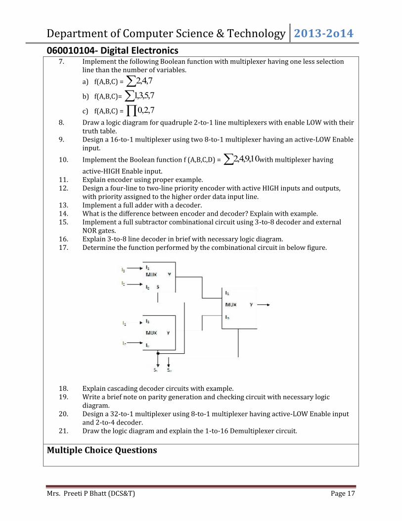
7. Implement the following Boolean function with multiplexer having one less selectionline than the number of variables.a) f(A,B,C) = 7,4,2b) f(A,B,C)= 7,5,3,1c) f(A,B,C) = 7,2,08. Draw a logic diagram for quadruple 2-to-1 line multiplexers with enable LOW with theirtruth table.9. Design a 16-to-1 multiplexer using two 8-to-1 multiplexer having an active-LOW Enableinput.10. Implement the Boolean function f (A,B,C,D) = 10,9,4,2 with multiplexer havingactive-HIGH Enable input.11. Explain encoder using proper example.12. Design a four-line to two-line priority encoder with active HIGH inputs and outputs,with priority assigned to the higher order data input line.13. Implement a full adder with a decoder.14. What is the difference between encoder and decoder? Explain with example.15. Implement a full subtractor combinational circuit using 3-to-8 decoder and externalNOR gates.16. Explain 3-to-8 line decoder in brief with necessary logic diagram.17. Determine the function performed by the combinational circuit in below figure.
18. Explain cascading decoder circuits with example.19. Write a brief note on parity generation and checking circuit with necessary logicdiagram.20. Design a 32-to-1 multiplexer using 8-to-1 multiplexer having active-LOW Enable inputand 2-to-4 decoder.21. Draw the logic diagram and explain the 1-to-16 Demultiplexer circuit.Multiple Choice Questions
Department of Computer Science & Technology 2013-2o14060010104- Digital Electronics
Mrs. Preeti P Bhatt (DCS&T) Page 18
1. A combinational circuit which is used to change a decimal number into an equivalentBCD number isa) Decoder b) Encoder c) Multiplexer d) Demultiplexer2. When an application, such as an encoder, calls for a unique response from a circuitcorresponding to a combination of its input variables, the two methods that best servethis purpose are the ________ and the _______.a) Case construct, truth tableb) If then statement, else statementc) VARIABLE,PROCESSd) FUNCTION TYPE3. A combinational circuit which is used to change a BCD number into an equivalentdecimal number is(a) Decoder b) Encoder c) Multiplexer d) Demultiplexer4. A combinational circuit which is used to send data coming from a single source to twoor more separate destinations is called as:(a) Decoder b) Encoder c) Multiplexer d) Demultiplexer5. How many data select lines are required for selecting eight inputs?a) 1b) 2c) 3d) 46. Convert BCD 0001 0111 to binary.a) 10101b) 10010c) 10001d) 110007. How many 3-line-to-8-line decoders are required for a 1-of-32 decoder?a) 1b) 2c) 4d) 88. A combinational circuit which is used to change a decimal number into an equivalentBCD number isa) Decoder b) Encoder c) Multiplexer d) Demultiplexer9. When an application, such as an encoder, calls for a unique response from a circuitcorresponding to a combination of its input variables, the two methods that best servethis purpose are the ________ and the _______.a) Case construct, truth tableb) If then statement, else statementc) VARIABLE,PROCESSd) FUNCTION TYPE10. A combinational circuit which is used to change a BCD number into an equivalentdecimal number is(a) Decoder (b) Encoder (c) Multiplexer (d) Demultiplexer11. A combinational circuit which is used to send data coming from a single source to two
Department of Computer Science & Technology 2013-2o14060010104- Digital Electronics
Mrs. Preeti P Bhatt (DCS&T) Page 19
or more separate destinations is called as:(a) Decoder (b) Encoder (c) Multiplexer (d) Demultiplexer12. How many data select lines are required for selecting eight inputs?a) 1b) 2c) 3d) 413. Convert BCD 0001 0111 to binary.a) 10101b) 10010c) 10001d) 1100014. How many 3-line-to-8-line decoders are required for a 1-of-32 decoder?a) 1b) 2c) 4d) 815. For the device shown here, let all D inputs be LOW, both S inputs be HIGH, and the ENinput be LOW. What is the status of the Y output?D0D1D2D3YS0S1EN a) LOWb) HIGHc) Don’t Cared) Cannot be determine16. For the device shown here, let all D inputs be LOW, both S inputs be HIGH, and the ENinput be HIGH. What is the status of the Y output?D0D1D2D3 YS0S1EN
MUX
MUX
Department of Computer Science & Technology 2013-2o14060010104- Digital Electronics
Mrs. Preeti P Bhatt (DCS&T) Page 20
a) LOWb) HIGHc) Don’t Cared) Cannot be determine17. How many 1-of-16 decoders are required for decoding a 7-bit binary number?a) 5b) 6c) 7d) 818. Which of the following statements accurately represents the two BEST methods of logiccircuit simplification?a) Boolean algebra and Karnaugh mappingb) Karnaugh mapping and circuit waveform analysisc) Actual circuit trial and error evaluation and waveform analysisd) Boolean algebra and actual circuit trial and error evaluation19. Which of the following combinations cannot be combined into K-map groups?a) Corners in the same rowb) Corners in the same columnc) Diagonal cornersd) Overlapping combinations20. The device shown here is most likely a ________.DS0 YOS1 1Y2Y
EN 3Ya) Comparatorb) Multiplexerc) Demultiplexerd) Parity generator21. A decoder can be used as a Demultiplexer by ________.a) tying all enable pins LOWb) tying all data-select lines LOWc) tying all data-select lines HIGHd) using the input lines for data selection and an enable line for data input22. Which of the following combinations of logic gates can decode binary 1101?a) One 4-input AND gateb) One 4-input AND gate, one OR gatec) One 4-input NAND gate, one inverterd) One 4-input AND gate, one inverter23. How many outputs would two 8-line-to-3-line encoders, expanded to a 16-line-to-4-lineencoder, have?a) 3 (b) 4 (c) 5 (d) 624. A data selector is also called a
Department of Computer Science & Technology 2013-2o14060010104- Digital Electronics
Mrs. Preeti P Bhatt (DCS&T) Page 21
a) De-multiplexer b) Priority encoder c) Decoder d) Multiplexer25. A decoder is nothing but a Demultiplexer withouta) Control inputs (b) Data input (c) Enable input (d) none of these26. A 1-of-8 octal decoder has eight outputs and decodes an input of ________ bits.a) Threeb) Twoc) Fourd) One27. BCD to Decimal decoder hasa) 10 inputs and 10 outputsb) 4 inputs and 10 outputsc) 10 inputs and 4 outputsd) None of aboveTrue/False1. A digital multiplexer can be used as demultiplexer.2. An encoder in which the highest and lowest value input digits are encodedsimultaneously is known as a priority encoder.3. Three select lines are required to address four data input lines.4. A combinatorial logic circuit has memory characteristics that "remember" the inputsafter they have been removed.5. A data selector is also called a demultiplexer.6. A digital circuit that converts coded information into a familiar or non-coded form isknown as an encoder.7. An exclusive-OR gate will invert a signal on one input if the other is always HIGH.8. The following combination is correct for an EVEN parity data transmission system:9. data = 100111100 and parity = 010. The CASE control structure is used when an expression has a list of possible values.11. When decisions demand one of many possible actions, the ELSIF control structure isused.12. The input at the 1, 2, 4, 8 inputs to a 4-line to 16-line decoder with active-low outputs is1110. As a result, output line 7 is driven LOW.13. A 2n-to-1 MUX can be used to implement a Boolean function with n + 1 variables.14. Encoder is having one output line.15. It is normal for more than one decoder output to be active at the same time.16. The select inputs to a multiplexer may also be called address lines.17. Basically, a multiplexer changes parallel data inputs to a serial output.18. A four-line multiplexer must have as inputs four data inputs and two select inputs19. A demultiplexer is a device that converts some code into a recognizable number orcharacter.20. The device that is an application of SOP logic is a multiplexer.Fill in the Blanks1. Multiplexers, demultiplexers, decoders, encoders are _____________ logic circuits.2. A multiplexer is having _____ output lines.
Department of Computer Science & Technology 2013-2o14060010104- Digital Electronics
Mrs. Preeti P Bhatt (DCS&T) Page 22
3. A circuit that can convert one of ten numerical keys pressed on a keyboard to BCD is a________.4. The largest truth table that can be implemented directly with an 8-line-to-1-line MUXhas ______.5. Parity generators and checkers use ________ gates.6. If there are n selection lines, then the number of maximum possible input lines is ____.7. Encoder is a combinational circuit that has 2n input lines and ____ output lines.8. A decoder is a special case of ____________________ without the input line.9. In a 1-to-16 demultiplexer, the number of control input will be ______.10. A decoder with an enable input can function as a ___________________.11. Parity generators and checkers use ________ gates.12. Parity generation and checking is used to detect _______.13. Parity checkers are circuits that detect ____ bit errors in the transmitted data word.14. ___________ can possibly be used for parallel-to-serial conversion.15. Octal to binary conversion can be done using __________.16. A 4-to-16 line decoder can be constructed using _______________ line decoders havingactive-LOW ENABLE inputs.UNIT5 : Flip-Flops
Short Questions1. List out the sequential circuit.2. List the types of flip-flops.3. Draw block diagram of sequential circuit.4. Define Flip Flop.5. List two types of edge triggered flip-flops.6. Draw a logic diagram of RS Flip-Flop with NAND gate.7. Explain the four condition of RS Flip-Flop.8. Draw a NOR implementation of RS Flip-Flop.9. What do you mean by clock?10. Define Propagation Delay.11. What is the forbidden condition?12. Draw a logic implementation of clocked RS Flip-Flop with its truth table.13. What do you mean by Edge Triggered Flip-Flop?14. What do you mean by Level Triggered Flip-Flop?15. Give a logic implementation of positive edge triggered edge detector circuit.16. What do you mean by frequency?17. What is race condition?18. List several devices that are built using J-K flip-flop.19. Give a logic implementation of J-K Flip-Flop with PRESET & CLEAR inputs.20. Explain the four condition of RS Flip-Flop.21. Draw a logic diagram of Toggle Flip-Flop using J-K Flip-Flop.22. What is D Flip-Flop?23. What do you mean by asynchronous inputs?24. Classify flip-flop as synchronous or asynchronous.25. List one type of asynchronous and three types of synchronous flip-flops.
Department of Computer Science & Technology 2013-2o14060010104- Digital Electronics
Mrs. Preeti P Bhatt (DCS&T) Page 23
26. List the different application of flip-flop.Long Questions1. Draw a truth table for following flip-flopsa) J-Kb) Dc) RSd) Clocked Rs.2. Draw a traditional logic symbols for the following flip-flopsa) J-Kb) Dc) RSd) Clocked Rs.3. Explain the Master-Slave Flip-Flop. How it overcome the race condition of J-K flip-flop.Use proper logic diagram.4. Differentiate combinational and sequential circuits.5. Differentiate synchronous or asynchronous inputs.6. Differentiate level-triggered and edge-triggered flip-flops.7. Give a brief note on edge triggered flip-flop using proper logic diagrams.8. Explain J-K flip-flop with PRESET and CLEAR inputs using proper logic diagrams andtruth tables.9. Explain J-K flip-flop using proper logic diagrams and truth tables.10. Explain R-S flip-flop using proper logic diagrams and truth tables.11. Explain Toggle flip-flop using proper logic diagrams and truth tables.12. Explain Clocked R-S flip-flop using proper logic diagrams and truth tables.13. Explain Clocked D flip-flop using proper logic diagrams and truth tables14. Explain two applications of flip-flops other than counters and registers.15. Explain how D flip-flop can be used to detect the sequence of edges.16. How we can say that J-K flip-flop is a universal flip-flop. Explain using logic diagrams.17. Explain the switch debouncing as an application of flip-flop.18. What is a flip-flop? Show the logic implementation of R-S flip flop having active-High Rand S inputs. Draw its truth table and mark the invalid entry.19. What is a clocked J-K flip flop? What improvement does it have over a clocked R-S flipflop?20. Differentiate D and T Flip Flop.21. Briefly describes the following flip flop timing parameters:a) Set-up time and hold time;b) Propagation delayc) Maximum clock frequency.Multiple Choice Questions1. Which statement BEST describes the operation of a negative-edge-triggered D flip-flop?a) The logic level at the D input is transferred to Q on NGT of CLK.b) The Q output is ALWAYS identical to the CLK input if the D input is HIGH.c) The Q output is ALWAYS identical to the D input when CLK = PGT.
Department of Computer Science & Technology 2013-2o14060010104- Digital Electronics
Mrs. Preeti P Bhatt (DCS&T) Page 24
d) The Q output is ALWAYS identical to the D input.2. Propagation delay time, tp, is measured from the ________.a) triggering edge of the clock pulse to the LOW-to-HIGH transition of the outputb) triggering edge of the clock pulse to the HIGH-to-LOW transition of the outputc) preset input to the LOW-to-HIGH transition of the outputd) clear input to the HIGH-to-LOW transition of the output3. How is a J-K flip-flop made to toggle?a) J = 0, K = 0b) J = 1, K = 0c) J = 0, K = 1d) J = 1, K = 14. How many flip-flops are required to produce a divide-by-128 device?a) 1b) 4c) 6d) 75. On a master-slave flip-flop, when is the master enabled?a) when the gate is LOWb) when the gate is HIGHc) both of the aboved) neither of the above6. One example of the use of an S-R flip-flop is as a(n):a) Racerb) astable oscillatorc) binary storage registerd) transition pulse generator7. Which of the following is correct for a gated D flip-flop?a) The output toggles if one of the inputs is held HIGH.b) Only one of the inputs can be HIGH at a time.c) The output complement follows the input when enabled.d) Q output follows the input D when the enable is HIGH.8. With regard to a D latch, ________.a) the Q output follows the D input when EN is LOWb) the Q output is opposite the D input when EN is LOWc) the Q output follows the D input when EN is HIGHd) the Q output is HIGH regardless of EN's input state9. How can the cross-coupled NAND flip-flop be made to have active-HIGH S-R inputs?a) It can't be done.b) Invert the Q outputs.c) Invert the S-R inputs.10. When is a flip-flop said to be transparent?a) when the Q output is opposite the inputb) when the Q output follows the inputc) when you can see through the IC packaging11. Which of the following is correct for a D latch?a) The output toggles if one of the inputs is held HIGH.b) Q output follows the input D when the enable is HIGH.c) Only one of the inputs can be HIGH at a time.
Department of Computer Science & Technology 2013-2o14060010104- Digital Electronics
Mrs. Preeti P Bhatt (DCS&T) Page 25
d) The output complement follows the input when enabled12. A correct output is achieved from a master-slave J-K flip-flop only if its inputs arestable while the:a) clock is LOWb) slave is transferringc) flip-flop is resetd) clock is HIGH13. What does the triangle on the clock input of a J-K flip-flop mean?a) level enabledb) edge-triggered14. On a positive edge-triggered S-R flip-flop, the outputs reflect the input condition when________.a) the clock pulse is LOWb) the clock pulse is HIGHc) the clock pulse transitions from LOW to HIGHd) the clock pulse transitions from HIGH to LOW15. What is the hold condition of a flip-flop?a) both S and R inputs activatedb) no active S or R inputc) only S is actived) only R is active16. The circuit that is primarily responsible for certain flip-flops to be designated as edge-triggered is the:a) edge-detection circuit.b) NOR latch.c) NAND latch.d) pulse-steering circuit.17. What is the significance of the J and K terminals on the J-K flip-flop?a) There is no known significance in their designations.b) The J represents "jump," which is how the Q output reacts whenever the clockgoes high and the J input is also HIGH.c) The letters were chosen in honor of Jack Kilby, the inventory of the integratedcircuit.d) All of the other letters of the alphabet are already in use.18. Which of the following is not generally associated with flip-flops?a) Hold timeb) Propagation delay timec) Interval timed) Set up time19. What is one disadvantage of an S-R flip-flop?a) It has no enable input.b) It has an invalid state.c) It has no clock input.d) It has only a single output.20. The output of a gated S-R flip-flop changes only if the:a) flip-flop is setb) control input data has changedc) flip-flop is reset
Department of Computer Science & Technology 2013-2o14060010104- Digital Electronics
Mrs. Preeti P Bhatt (DCS&T) Page 26
d) input data has no change21. An invalid condition in the operation of an active-HIGH input S-R latch occurs when________.a) HIGHs are applied simultaneously to both inputs S and Rb) LOWs are applied simultaneously to both inputs S and Rc) a LOW is applied to the S input while a HIGH is applied to the R inputd) a HIGH is applied to the S input while a LOW is applied to the R inputTrue/False1. Flip-Flop outputs are always opposite or complementary.2. Combinational circuit is having memory unit.3. Flip flop is 1bit storage unit.4. Master-slave J-K flip-flops are called pulse-triggered or level-triggered devices becauseinput data is read during the entire time the clock pulse is at a LOW level.5. Gated S-R flip-flops are called asynchronous because the output responds immediatelyto input changes.6. Asynchronous inputs will cause the flip-flop to respond immediately with regard to theclock input.7. For an S-R flip-flop to be set or reset, No change will occur in the output.8. A gated S-R flip-flop goes into the SET condition when S is HIGH, R is LOW, and EN isHIGH.9. A negative edge-triggered flip-flop will accept inputs only when the clock is LOW.10. The term CLEAR always means that Q = 0, Q = 1.11. PRESET and CLEAR inputs are normally synchronous.12. The Q output of a flip-flop is normally HIGH when the device is in the "CLEAR" or"RESET" state.13. An input which can only be accepted when an enable or trigger is present is calledasynchronous.14. Inputs that cause the output of a flip-flop to change instantaneously are asynchronous.15. The J-K flip-flop eliminates the invalid state by toggling when both inputs are high andthe clock transitions.16. A D-type latch is able to change states and "follow" the D input regardless of the level ofthe ENABLE input.17. A positive edge-triggered flip-flop changes states with a HIGH-to-LOW transition on theclock input.18. A D latch has one data-input line.19. Edge-triggered flip-flops can be identified by the triangle on the clock input.20. The S-R flip-flop has no invalid or unused state.21. Some flip-flops have invalid states.22. Simple gate circuits, combinational logic, and transparent S-R flip-flops aresynchronous.23. A flip-flop is in the CLEAR condition when Q = 1, Q = 0.24. Pulse-triggered or level-triggered devices are the same.25. A D flip-flop is constructed by connecting an inverter between the SET and clock
Department of Computer Science & Technology 2013-2o14060010104- Digital Electronics
Mrs. Preeti P Bhatt (DCS&T) Page 27
terminals.26. It takes four flip-flops to act as a divide-by-4 frequency divider.27. Flip-flops are wired together to form counters registers and memory devices.Fill in the Blanks1. _______ are the basic building blocks of combinational logic circuits.2. _______ are the basic building blocks of sequential logic circuits.3. The “D” in flip-flop stands for ________ or data.4. f an active-HIGH S-R latch has a 0 on the S input and a 1 on the R input and then the Rinput goes to 0, the latch will be ________.5. On a J-K flip-flop, when is the flip-flop in a hold condition J = _____ , K = ______.6. If an input is activated by a signal transition, it is ________.7. For an S-R flip-flop to be set or reset, the respective input must be ________.S8. Assume a J-K flip-flop has 1s on the J and K inputs. The next clock pulse will cause theoutput to ________.9. In synchronous systems, the exact times at which any output can change state aredetermined by a signal commonly called the ________.10. When the output of the NOR gate S-R flip-flop is Q = 0 and , the inputs are _____, ______.11. A major drawback to an SR Flip Flop is its ________.12. When the output of the NOR gate S-R flip-flop is in the HOLD state (no change), theinputs are ________.13. The signal used to identify edge-triggered flip-flops is ________.14. An edge-triggered flip-flop can change states only when ________.15. When both inputs of a J-K pulse-triggered FF are high and the clock cycles, the outputwill ________.16. The term hold always means ________.17. A gated S-R flip-flop goes into the CLEAR condition when _________________.18. If an input is activated by a signal transition, it is ________.19. A flip-flop operation is described as a toggle when the result after a clock is ________.20. A positive edge-triggered flip-flop will accept inputs only when the clock ________.21. The advantage of a J-K flip-flop over an S-R FF is that ________.22. A S-R flip-flop is in the hold condition whenever ________.23. The toggle mode is the mode in which a(n) ________ changes states for each clock pulse.
UNIT6 : Counters and Registers
Short Questions1. What do you mean by serial shifting?2. Define modulus of counter.3. Is counter is a sequential circuit or combinational circuit or sequential circuit with orwithout combination logic devices?4. To shift 4 bit binary data out from SISO shift register what will be the input bits to ashift register?5. What do you mean by modulus of counter?
Department of Computer Science & Technology 2013-2o14060010104- Digital Electronics
Mrs. Preeti P Bhatt (DCS&T) Page 28
6. Give the steps to design cascading decoder circuits. Also provide logic diagram.7. Why asynchronous counters are also known as serial counters?8. In what type of shift register complete binary number can be loaded into it in oneoperation and then have shifted out one bit at a time?9. In what type of shift register data can be entered only one bit at a time but has all databits available as outputs?10. What are counters with arbitrary counts sequence?11. Give at least one IC type number for four bit binary ripple counter.12. Give at least one IC type number for four bit synchronous counter.13. Give at least one IC type number for eight bit serial-in, serial-out shift register.14. Give at least one IC type number for bidirectional universal shift register.Long Questions1. Define parallel counters. Draw the logic diagram for synchronous counter that countfrom 0000 to 1111. Explain how it counts the numbers.2. Differentiate combinational circuits and sequential circuits.3. Is PRESET & CLEAR are asynchronous inputs? Justify your answer.4. Draw logic diagram for 4 bit Parallel In Parallel Out shift register and explain how it isused to shift data serially.5. Draw the waveforms to shift the binary number 1010 into the register in Fig.1.
6. Name the four basic types of shift register, and draw a block diagram for each.7. Differentiate between asynchronous and synchronous counter.8. Differentiate between UP, DOWN and UP/DOWN counter.9. Differentiate between Presentable and clearable counter.10. Differentiate between BCD and Decade counter.11. What is the difference between four-bit binary UP and four-bit binary DOWN counter?12. How does architecture of an asynchronous UP counter differ from that of DOWNcounter?13. Why is maximum usable clock frequency in case of synchronous counter independentof that of size of counter?14. What do you mean by shift register? Explain the Serial-In-Serial-Out shift register.15. Design a Mod-10 counter. Also draw the timing waveforms.16. Explain parallel counters. Give the circuit representation of 4-bit synchronous counterand explain its working.17. What are counters with arbitrary counts sequence? Briefly describe the producers fordesigning a counter with a given arbitrary count sequence.
Department of Computer Science & Technology 2013-2o14060010104- Digital Electronics
Mrs. Preeti P Bhatt (DCS&T) Page 29
Multiple Choice Questions1. The minimum number of flip-flops needed to construct a BCD decade counter isa) 4b) 3c) 10d) 22. A shift counter comprising five flip-flops with an inverse feedback from the output ofMSB flip-flop to the input of the LSB flip-flop is aa) Divide-by-32- counterb) Divide-by-10- counterc) Divide-by-5- counterd) Five-bit shift counter3. On the fifth clock pulse, a 4-bit Johnson sequence is Q0 = 0, Q1 = 1, Q2 = 1, and Q3 = 1.On the sixth clock pulse, the sequence is ________.a) Q0 = 1, Q1 = 0, Q2 = 0, Q3 = 0b) Q0 = 1, Q1 = 1, Q2 = 1, Q3 = 0c) Q0 = 0, Q1 = 0, Q2 = 1, Q3 = 1d) Q0 = 0, Q1 = 0, Q2 = 0, Q3 = 14. The bit sequence 0010 is serially entered (right-most bit first) into a 4-bit parallel outshift register that is initially clear. What are the Q outputs after two clock pulses?a) 0000b) 0010c) 1000d) 11115. What is a shift register that will accept a parallel input, or a bidirectional serial loadand internal shift features, called?a) tristateb) end aroundc) universald) conversion6. On the third clock pulse, a 4-bit Johnson sequence is Q0 = 1, Q1 = 1, Q2 = 1, and Q3= 0.On the fourth clock pulse, the sequence is ________.a) Q0 = 1, Q1 = 1, Q2 = 1, Q3 = 1b) Q0 = 1, Q1 = 1, Q2 = 0, Q3 = 0c) Q0 = 1, Q1 = 0, Q2 = 0, Q3 = 0d) Q0 = 0, Q1 = 0, Q2 = 0, Q3 = 07. A bidirectional 4-bit shift register is storing the nibble 1101. Its input isHIGH. The nibble 1011 is waiting to be entered on the serial data-input line. After threeclock pulses, the shift register is storing ________.a) 1101b) 0111c) 0001d) 11108. How can parallel data be taken out of a shift register simultaneously?a) Use the Q output of the first FF.b) Use the Q output of the last FF.
Department of Computer Science & Technology 2013-2o14060010104- Digital Electronics
Mrs. Preeti P Bhatt (DCS&T) Page 30
c) Tie all of the Q outputs together.d) Use the Q output of each FF.9. What is meant by parallel load of a shift register?a) All FFs are preset with data.b) Each FF is loaded with data, one at a time.10. How many flip-flops are required to make a MOD-32 binary counter?a) 3b) 45c) 5d) 611. Using four cascaded counters with a total of 16 bits, how many states must be deletedto achieve a modulus of 50,000?a) 50,000b) 65,536c) 25,536d) 15,53612. The terminal count of a modulus-11 binary counter is ________.a) 1010b) 1000c) 1001d) 110013. Synchronous counters eliminate the delay problems encountered with asynchronouscounters because the:a) input clock pulses are applied only to the first and last stagesb) input clock pulses are applied only to the last stagec) input clock pulses are not used to activate any of the counter stagesd) input clock pulses are applied simultaneously to each stage14. What is the difference between combinational logic and sequential logic?a) Combinational circuits are not triggered by timing pulses, sequential circuits aretriggered by timing pulses.b) Combinational and sequential circuits are both triggered by timing pulses.c) Neither circuit is triggered by timing pulses.15. A BCD counter is a ________.a) Binary counter.b) Full-modulus counter.c) Decade counter.d) Divide-by-10 counter.16. A five bit countera) Has a modulus of 5.b) Has a modulus of 2.c) Has modulus that is less than or equal to 32.d) Cant not have a modulus that is greater than 32.e) Both c and d are true.17. All BCD countersa) Are decade counters because all decades counters are BCD counters.b) Are not decade’s counters.c) Have a modulus of 10.d) Are constructed with only presettable D flip-flops.18. A counter that has a modulus of 64 should use minimum of
Department of Computer Science & Technology 2013-2o14060010104- Digital Electronics
Mrs. Preeti P Bhatt (DCS&T) Page 31
a) 6 flip-flopsb) 6 J-K type flip-flopsc) 6 D flip-flopsd) 64 flip-flops19. A MOD-32 binary synchronous counter would requirea) 6 flip-flops and 3 AND gatesb) 5 flip-flopsc) 5 flip-flops and 3 AND gatesd) None of these20. In what type of shift register do we have access to only the leftmost and rightmost flip-flops?a) Serial-in serial-out shift registerb) Serial-in parallel-out shift registerc) Parallel-in serial-out shift registerd) Parallel-in Parallel-out shift registerTrue/False1. Bidirectional shift registers can shift data either right or left.2. In many cases, counters must be strobed in order to eliminate glitches.3. A state diagram is a table of states.4. A ripple counter is an asynchronous counter.5. The MOD number of a Johnson counter will always be equal to one-half the number offlip-flops in the counter.6. To cascade is to connect in parallel.7. Cascade means to connect the Q output of one flip-flop to the clock input of the next.8. In a synchronous counter, each state is clocked by the same pulse.9. Basic counters can be cascaded in parallel to increase the number of data bits that thecounter can handle.10. Dependency notation is no longer used.11. A parallel in/serial out shift register enters all data bits simultaneously and transfersthem out one bit at a time.12. Generally speaking, the synchronous counter requires more circuitry than anasynchronous counter.13. Another term used to describe up/down counters is bidirectional.14. When implementing a complete system application using IC counter chips, outputdevices such as LED indicators must be configured to operate from the counteroutputs.15. One of the stages in a register consists of a latch.16. There are several ways to construct a stepper motor to achieve digitally controlledstepping action. One possibility is to construct four stator coils set up as four pole pairs,each 45° apart and using three ferromagnetic pairs spaced 60° apart.Fill in the Blanks1. Assume a LOW logic level is placed on the SHIFT/LOAD input of a 74195 shift register.The output will change ________.2. A Johnson counter, constructed with N flip-flops, has ____________unique states?
Department of Computer Science & Technology 2013-2o14060010104- Digital Electronics
Mrs. Preeti P Bhatt (DCS&T) Page 32
3. A type of shift register that requires access to the Q outputs of all stages is ________.4. An 8-bit serial in/parallel out shift register is clocked at 4 MHz and is used to delay aserial digital signal by 1.25 s. The output that has the proper delay is ________.5. A 4-bit ring counter is loaded with a single 1. The frequency of any given output is________.6. Shifting a binary number to the left by one position is equivalent to ________.7. Assume a 4-bit Johnson counter is initially cleared. After the first clock pulse the outputis 0001. After the next clock pulse the output will be ________.8. A reliable method for eliminating decoder spikes is the technique called ________.9. A decade counter will count through decimal ________.10. ________ counters are often used whenever pulses are to be counted and the resultsdisplayed in decimal.11. The technique used by one-shots to respond to an edge rather than a level is called________.12. A J-K flip-flop is reset and must stay reset after the clock pulse. This transition requiresthat ________.13. The ________ counter in the Altera library has controls that allow it to count up or down,and perform synchronous parallel load and asynchronous cascading.14. A BCD counter has ________ states.15. The decimal equivalent of the largest number that can be stored in a 4-bit binarycounter is ________.