51
Deploying IPv6 in the Internet Edge Last Updated: May 1, 2012 Building Architectures to Solve Business Problems

Deploying IPv6 in the Internet EdgeLast Updated: May 1, 2012
Building Architectures to Solve Business Problems

Cisco Validated Design2

About the Author
3
Shannon McFarland
About the Author
Shannon McFarland, Principal Engineer, Office of the CTO, Cisco Systems
Shannon McFarland, CCIE #5245, is a Principal Engineer in the Office of the CTO and is focused
on Enterprise IPv6 deployment, VDI, and Data Center technologies. Shannon has been respon-
sible for the Enterprise IPv6 design and deployment effort at Cisco for the last 10 years as well
as application design for Data Center environments for the last 6 years.. He has authored many
technical papers and Cisco Validated Design guides, is a contributor to Cisco Press books, and
is a frequent speaker at Cisco Live and other industry conferences. He co-authored a Cisco
Press book, "IPv6 in Enterprise Networks". Shannon has been at Cisco for 12 years

4About Cisco Validated Design
About Cisco Validated Design (CVD) Program
The CVD program consists of systems and solutions designed, tested, and documented to facili-
tate faster, more reliable, and more predictable customer deployments. For more information visit
http://www.cisco.com/go/designzone.
ALL DESIGNS, SPECIFICATIONS, STATEMENTS, INFORMATION, AND RECOMMENDATIONS (COLLEC-
TIVELY, "DESIGNS") IN THIS MANUAL ARE PRESENTED "AS IS," WITH ALL FAULTS. CISCO AND ITS SUP-
PLIERS DISCLAIM ALL WARRANTIES, INCLUDING, WITHOUT LIMITATION, THE WARRANTY OF
MERCHANTAB
FROM A COUR
SUPPLIERS BE
INCLUDING, W
THE USE OR IN
OF THE POSS
THE DESIGNS
THEIR APPLICA
OTHER PROFE
THEIR OWN TE
DEPENDING O
The Cisco imp
University of C
tem. All rights r
Cisco and the C
countries. A lis
party trademar
does not imply
Any Internet Pr
actual address
grams, and oth
actual IP addre
Deploying IPv6
© 2011 Cisco
(CVD) Program
ILITY, FITNESS FOR A PARTICULAR PURPOSE AND NONINFRINGEMENT OR ARISING
SE OF DEALING, USAGE, OR TRADE PRACTICE. IN NO EVENT SHALL CISCO OR ITS
LIABLE FOR ANY INDIRECT, SPECIAL, CONSEQUENTIAL, OR INCIDENTAL DAMAGES,
ITHOUT LIMITATION, LOST PROFITS OR LOSS OR DAMAGE TO DATA ARISING OUT OF
ABILITY TO USE THE DESIGNS, EVEN IF CISCO OR ITS SUPPLIERS HAVE BEEN ADVISED
IBILITY OF SUCH DAMAGES.
ARE SUBJECT TO CHANGE WITHOUT NOTICE. USERS ARE SOLELY RESPONSIBLE FOR
TION OF THE DESIGNS. THE DESIGNS DO NOT CONSTITUTE THE TECHNICAL OR
SSIONAL ADVICE OF CISCO, ITS SUPPLIERS OR PARTNERS. USERS SHOULD CONSULT
CHNICAL ADVISORS BEFORE IMPLEMENTING THE DESIGNS. RESULTS MAY VARY
N FACTORS NOT TESTED BY CISCO.
lementation of TCP header compression is an adaptation of a program developed by the
alifornia, Berkeley (UCB) as part of UCB’s public domain version of the UNIX operating sys-
eserved. Copyright © 1981, Regents of the University of California.
isco Logo are trademarks of Cisco Systems, Inc. and/or its affiliates in the U.S. and other
ting of Cisco's trademarks can be found at http://www.cisco.com/go/trademarks. Third
ks mentioned are the property of their respective owners. The use of the word partner
a partnership relationship between Cisco and any other company. (1005R)
otocol (IP) addresses and phone numbers used in this document are not intended to be
es and phone numbers. Any examples, command display output, network topology dia-
er figures included in the document are shown for illustrative purposes only. Any use of
sses or phone numbers in illustrative content is unintentional and coincidental.
in the Internet Edge
Systems, Inc. All rights reserved.

Deploying IPv6 in the Internet Edge
This document helps customers with planning and deploying IPv6 in the enterprise Internet edge (IE). This document does not introduce Internet edge design fundamentals, IPv6 theory, or IPv4-to-IPv6 feature comparisons, but rather addresses specific considerations for deploying IPv6 at the enterprise edge to serve IPv6 content and services to Internet users.
IntroductionOver the last several years enterprises have primarily been focused on IPv6 business cases, gap analysis on features, platform support, and performance. Those that have deployed have been focused on three main strategies for IPv6 implementation. These three strategies have been dictated by time and use cases. The three common implementation strategies are:
• Core-to-Edge—This implementation strategy has been focused on the deployment of IPv6 in the core layers of the network where there are fewer components to touch (software/hardware changes). The implementation of IPv6 can be done in a “ships-in-the-night” approach where enabling IPv6 does not impact IPv4 production traffic. As time goes on and important lessons are learned (addressing, summarization, performance, etc.), deployment of IPv6 moves towards the edges over time. This strategy is perfectly suited for those who want to begin their IPv6 deployment, but have no defined time frame or concrete drivers.
• Edge-to-Core—This implementation strategy is more bound to a specific use case with a specific time frame. Many enterprises, to include hardware and/or software vendors, need to get their products built to support IPv6. This includes connecting development groups, labs, external research groups, and others so that they can get operational experience with IPv6 and develop platforms that support IPv6. They may not have the luxury of time to go in and dual stack the enterprise environment so, instead, they build an overlay network based on a combination of dual stack where they can and tunnels where they must. This overlay network most often begins at the edges of the network, such as the campus access/distribution layers, branch offices, lab networks, and data center access/aggregation layers. Building the overlay network allows for almost immediate access to an IPv6-enabled environment by developers, engineers, IT staff, and pilot groups. As time goes on, the underlying infrastructure can be dual stack enabled. This strategy is perfectly suited for those who need to work with IPv6 in the near-term, but cannot fully dual stack enable the entire environment.
• Internet Edge-only—This implementation strategy is now the most pervasive of all three. It allows an enterprise to connect critical content and services to the Internet over IPv6, which allows for business continuity of revenue generation regardless of the protocol that a customer or partner uses
Corporate Headquarters:
Copyright © 2011 Cisco Systems, Inc. All rights reserv
Cisco Systems, Inc., 170 West Tasman Drive, San Jose, CA 95134-1706 USA

Introduction
to reach those services. Recent examples of deployments include online retailers, banking and airlines. The movement from 3G to 4G (LTE) as well as dual and single-stacked (IPv6 only) mobile devices will accelerate the need to have public-facing portals assessable via IPv6. Many enterprises will have a two-pronged approach to IPv6, where they quickly deploy enough IPv6 at their Internet edge to ensure business continuity over the next-generation protocol, while taking a longer-term and slower rollout approach using the core-to-edge or edge-to-core models.
The core-to-edge and edge-to-core models are discussed in detail in the CVDs Deploying IPv6 in Campus Networks (http://www.cisco.com/en/US/docs/solutions/Enterprise/Campus/CampIPv6.html) and Deploying IPv6 in Branch Networks (http://www.cisco.com/en/US/docs/solutions/Enterprise/Branch/BrchIPv6.html).
The focus of this CVD is to show basic deployment options for the following scenarios:
• Full dual stack (DS)—Full end-to-end dual stack deployment from an IPv6-enabled Internet Service Provider (ISP) all the way through the Internet edge to include routing, firewall, intrusion prevention, server load balancing, and Web server connectivity on a server virtualized environment (VMware® ESXi 5.0).
• Server load balanced IPv6-to-IPv4 (SLB64)—IPv6-enabled ISP connection through the Internet edge security and application services tier with IPv6-to-IPv4 integrated server load balancing and translation being performed on the Cisco Application Control Engine (ACE).
• Stateful Network Address Translated IPv6-to-IPv4 model (NAT64)—IPv6-enabled ISP connection through the Internet edge security tier with IPv6-to-IPv4 translation being performed on a Cisco 1000 Series Aggregation Services Router (ASR).
• Locator/ID Separation Protocol (LISP)—IPv6 access over a non-IPv6-enabled ISP using LISP.
Document ObjectivesThe deployment of IPv6 in the enterprise Internet edge can be accomplished in a wide range of ways. The deployment models discussed in this CVD are not to be taken as the only way to accomplish your goals, but they are well tested and deployed by customers all over the world. There is just enough detail included for you to gather the basics you need to be successful in your own deployment. Design elements such as ISP peering, BGP best practices, and Internet-facing security best practices are not discussed. Most of the best practices you currently use for IPv4 peering and Internet edge design easily transfer to IPv6.
The reader must be familiar with common Internet edge design best practices recommendations as well as the basics of IPv6 and associated coexistence mechanisms. The prerequisite knowledge can be acquired through many documents and training opportunities available both through Cisco and the industry at large. The following are a few recommended information resources for these areas of interest:
• Cisco Design Zonehttp://www.cisco.com/en/US/netsol/ns742/networking_solutions_program_category_home.html
• Cisco IPv6 http://www.cisco.com/ipv6
• IPv6 in Enterprise Networks by Shannon McFarland, Muninder Sambi, Nikhil Sharma, Sanjay Hooda (ISBN-10:1-58714-227-9; ISBN-13: 978-1-58714-227-7)http://www.ciscopress.com/bookstore/product.asp?isbn=1587142279
• Deploying IPv6 Networks by Ciprian P. Popoviciu, Eric Levy-Abegnoli, Patrick Grossetete (ISBN-10:1-58705-210-5; ISBN-13:978-1-58705-210-1)http://www.ciscopress.com/bookstore/product.asp?isbn=1587052105&rl=1
6Deploying IPv6 in the Internet Edge

General Concepts
• IPv6 Security by Scott Hogg, Eric Vyncke (ISBN-10:1-58705-594-5; ISBN-13: 978-1-58705-594-2)http://www.ciscopress.com/bookstore/product.asp?isbn=1587055945
• Cisco LISP http://lisp.cisco.com/
• Cisco Smart Business Architecturehttp://www.cisco.com/en/US/netsol/ns982/networking_solutions_program_home.html
Document Format and Naming ConventionsThis document provides an overview of the various Internet edge IPv6 deployment models and general deployment considerations and also provides the implementation details for each model.
The following abbreviations are used throughout this document when referring to the Internet edge IPv6 deployment models:
• Dual stack (DS)
• Server load balanced IPv6-to-IPv4 (SLB64)
• Stateful Network Address Translated IPv6-to-IPv4 (NAT64)
• Locator/ID Separation Protocol (LISP)
User-defined properties such as access control list (ACL) names and policy definitions are shown in ALL CAPS to differentiate them from command-specific policy definitions.
General ConceptsThere are a few concepts that help dictate which Internet edge design you start with, including:
• ISP Peering Support
• IPv6 Addressing Architecture
• Platform, Application, and Operating System Support
• Budget
• Time
Very often, an enterprise reviews all of these elements and decides whether taking an end-to-end dual-stack approach can or should be used.
We discuss, at a high-level, a few of these elements so you have a basic understanding of what many enterprises face in planning and deploying IPv6.
ISP Peering SupportIt is up to you to reach out to your various ISPs and understand their current and planned support for IPv6. This is not just a “do you support IPv6: yes or no” kind of discussion, as any of them can say “yes” if that is the only level of depth you explore. You need to have a comprehensive list of required items just like you do when you negotiate any of your ISP services. Some of these may include:
• Do you support IPv6 over the same link(s) as my existing IPv4 connection (i.e. dual stack peering)?
• Do you have a separate Service Level Agreement (SLA) for IPv6 or is it the same as IPv4?
7Deploying IPv6 in the Internet Edge

General Concepts
• Do you support BGP peering over IPv6?
• What is the maximum prefix length accepted by the ISP?
• Do you charge an extra fee for IPv6 services?
• What is your performance support for IPv6?
• What is your high availability support for IPv6? (often dictated in the SLA)
• Do you support IPv6 at ALL of my peering points?
• Can I get detailed usage and outage reporting like I have with IPv4?
• If using hosted or cloud services:
– What is the maximum prefix length offered by the cloud provider?
– Can I access my provisioning and billing portal over IPv6?
– Do you support global IPv6 addressing for virtual machines in your environment?
This is a very small list of items to consider, but you can see that you would probably ask most of these questions of any ISP with which you wanted to peer. Additional questions to ask can be found at: http://docwiki.cisco.com/wiki/What_To_Ask_From_Your_Service_Provider_About_IPv6. Also, you can check on ISP IPv6 reachability at: http://www.bgp4.as/looking-glasses.
Quite a few ISPs do not yet have native IPv6 support at every single peering point they have, so do not be surprised if they offer you either a separate circuit or tunnel interface just for IPv6 (e.g., manually configured tunnel, GRE, MPLS VPN) to another peering point or tell you that they do not support IPv6 at all. This is a critical point that should not be overlooked as this has a direct impact on your business operations. More and more ISPs are adding robust IPv6 support to their list of services, but it can be hit-or-miss depending on where you are, the type of peering arrangement you have (e.g., MPLS), and if you are working with a Tier 1 provider or below. Another option if your existing ISP cannot meet your needs is to use a tunnel broker, such as Hurricane Electric (http://tunnelbroker.net/), or a similar provider who can offer you both native or tunneled transit services just for IPv6.
Common peering arrangements with ISP(s) can look like Figure 1. Basic considerations for these options include:
• Single link—The single ISP option is very straightforward. The provider would add IPv6 to the existing circuit with an IPv6 route that points to your edge router for your IPv6 prefix. You would add an IPv6 default route pointing to the ISP gateway. In some cases you may have a dedicated IPv6-only circuit in addition to your existing IPv4 circuit, but this is rare and costly.
• Dual links—The single ISP option is one of many combinations that you can have. You may have dozens of peering links all over the world with just a single ISP. Regardless of the number of links, the basic design principles used with IPv4 would mostly apply to IPv6; BGP peering, default route injection versus full Internet route table support, equal cost versus primary/standby paths, Unicast Reverse Path Forwarding (uRPF), and route aggregation, among others, would be a part of the basic design.
• Multi-homed—The multi-region option is similar to the previous option, only with multiple providers. Some of the complications involved here involve IPv6 addressing and the advertisement of your single or, perhaps, multiple IPv6 prefixes. This is discussed further in IPv6 Addressing Architecture below.
8Deploying IPv6 in the Internet Edge

General Concepts
Figure 1 Common ISP Peering Arrangements
IPv6 Addressing ArchitectureThe most obvious task you have to perform is obtaining an IPv6 prefix by going to a Regional Internet Registry (RIR) such as ARIN, AfriNIC, APNIC, LACNIC, or RIPE (this space is known as Provider Independent [PI]) or your ISP. Each RIR has their own policy on obtaining IPv6 addressing and the size of the prefix available. More information can be found at each RIR site:
• ARIN—https://www.arin.net/policy/nrpm.html
• AfriNIC—http://www.afrinic.net/IPv6/
• APNIC—http://www.apnic.net/policy/ipv6-address-policy
• LACNIC—http://lacnic.net/en/politicas/ipv6.html
• RIPE—http://www.ripe.net/ripe/docs/ripe-523
Obtaining addressing is not hard, but knowing what size of prefix to obtain and whether or not you should obtain space in each region you peer in (or will one day) takes much more planning. This is a task that only you can do adequately. Enterprises are constantly reaching out to their vendors for support for something that they really are best suited to do by themselves. This is just addressing, route summarization, and IP Address Management (IPAM) considerations you already know. Where things get interesting is when dealing with multi-homing and whether or not you should obtain one large PI block from one RIR and use it everywhere or should you obtain a prefix per RIR (assuming you are using PI space) and work out the internal and external routing configuration to make that work. Today, many enterprises have multiple IPv4 prefixes and then perform Network Address Translation—Port Translation (NAPT - RFC2663) across their entire internal infrastructure (or parts of it). Today, this does not truly exist in IPv6 in the exact same way.
2921
20
ISP 1
Enterprise
DefaultRoute
Single LinkSingle ISP
ISP 1
Enterprise
Dual LinksSingle ISP
POP1 POP2
USA
BGP BGP
Enterprise
Multi-HomedMulti-Region
POP1 POP2
Europe
POP1 POP2
9Deploying IPv6 in the Internet Edge

General Concepts
With IPv6, translation-based options such as NAT64 exist, but are meant to be used for purposes other than pure topology hiding and break the overall end-to-end model IPv6 has as a primary directive (see Network Address Translation IPv6-to-IPv4 (NAT64)). RFC6296 - IPv6-to-IPv6 Network Prefix Translation or NPTv6 (http://www.ietf.org/rfc/rfc6296.txt) define a methodology to allow for the use of a Global Unicast Address (GUA) on the “outside” of an NPTv6 gateway and another GUA (http://www.ietf.org/rfc/rfc3587.txt) or Unique Local Address (ULA - http://www.ietf.org/rfc/rfc4193.txt) on the “inside” of the NPTv6 gateway. As the name implies, only the “Prefix” is translated between address spaces. NPTv6 was proposed solely for the use of multi-homing when an enterprise needs to translate between IPv6 prefixes but still maintain some level of end-to-end reachability.
Note As of the end of 2011 NPTv6 is not yet available on Cisco products, therefore it is not included as a design option.
Finally, there is the task of actually designing the address space to be used inside the Internet edge. Guidance is hard to offer, as every Internet edge is different. There are a number of addressing design choices that include a varying number of devices, links, sizes, and other requirements. Cisco has published an IPv6 addressing guide that can be referenced and there are several available by searching the Internet.
Cisco IPv6 Address Resources
• http://www.cisco.com/web/strategy/docs/gov/IPv6_WP.pdf
• http://www.cisco.com/en/US/docs/solutions/Enterprise/Borderless_Networks/Smart_Business_Architecture/August2011/SBA_Ent_BN_IPv6AddressingGuide-August2011.pdf
More information about the addressing used in this document can be found in Internet Edge IPv6 Deployment.
Platform, Application, and Operating System SupportPerforming a complete and thorough gap analysis on your platforms and associated software is of paramount importance and must be performed well in advance of the actual deployment. The hardware and software support for IPv6 dictates the design you pursue. More and more channel partners are establishing dedicated service offerings that are focused on helping enterprise customers navigate the inventory, gap analysis, and remediation of IPv6 across the entire infrastructure. Cisco Advanced Services also has a service that can help you with your pre- and post-deployment needs. More information can be found at the following link or by contacting your Cisco account team or partner: http://www.cisco.com/en/US/services/ps6887/ps10716/docs/IPv6_Service_Overview.pdf.
IPv6 support within Cisco’s portfolio has increased significantly in recent years, especially within routing, security, and application-focused platforms. Although not every platform from Cisco is listed, there is an excellent resource for mapping IPv6 feature support to versions of code on certain platforms: http://www.cisco.com/web/solutions/netsys/ipv6/knowledgebase/index.html.
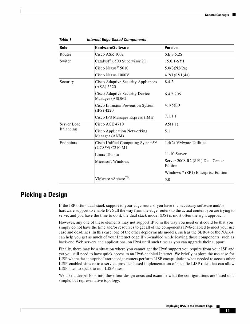
In this CVD, a wide range of platforms was used to fill specific roles within the Internet edge architecture. The platforms listed in Table 1 are not the only choices you have, but they are well known platforms and commonly found in Internet edge designs.
10Deploying IPv6 in the Internet Edge
General Concepts
Picking a DesignIf the ISP offers dual-stack support to your edge routers, you have the necessary software and/or hardware support to enable IPv6 all the way from the edge routers to the actual content you are trying to serve, and you have the time to do it, the dual stack model (DS) is most often the right approach.
However, any one of these elements may not support IPv6 in the way you need or it could be that you simply do not have the time and/or resources to get all of the components IPv6-enabled to meet your use case and deadlines. In this case, one of the other deployments models, such as the SLB64 or the NAT64, can help you get as much of your Internet edge IPv6-enabled while leaving those components, such as back-end Web servers and applications, on IPv4 until such time as you can upgrade their support.
Finally, there may be a situation where you cannot get the IPv6 support you require from your ISP and yet you still need to have quick access to an IPv6-enabled Internet. We briefly explore the use case for LISP where the enterprise Internet edge routers perform LISP encapsulation when needed to access other LISP-enabled sites or to a service provider-based implementation of specific LISP roles that can allow LISP sites to speak to non-LISP sites.
We take a deeper look into these four design areas and examine what the configurations are based on a simple, but representative topology.
Table 1 Internet Edge Tested Components
Role Hardware/Software Version
Router Cisco ASR 1002 XE 3.5.2S
Switch Catalyst® 6500 Supervisor 2T
Cisco Nexus® 5010
Cisco Nexus 1000V
15.0.1-SY1
5.0(3)N2(2a)
4.2(1)SV1(4a)
Security Cisco Adaptive Security Appliances (ASA) 5520
Cisco Adaptive Security Device Manager (ASDM)
Cisco Intrusion Prevention System (IPS) 4220
Cisco IPS Manager Express (IME)
8.4.2
6.4.5.206
4.1(5)E0
7.1.1.1
Server Load Balancing
Cisco ACE 4710
Cisco Application Networking Manager (ANM)
A5(1.1)
5.1
Endpoints Cisco Unified Computing System™ (UCS™) C210 M1
Linux Ubuntu
Microsoft Windows
VMware vSphereTM
1.4(2) VMware Utilities
11.10 Server
Server 2008 R2 (SP1) Data Center Edition
Windows 7 (SP1) Enterprise Edition
5.0
11Deploying IPv6 in the Internet Edge
Internet Edge IPv6 Deployment
Internet Edge IPv6 DeploymentThis section is focused on the configuration of the four design options mentioned earlier. The topology is exactly the same between all four designs, but in three of the four (SLB64, NAT64, and LISP), IPv6 is missing from certain parts of the topology to show what to do when you are missing IPv6 support, but still need to get IPv6 content to the Internet.
As mentioned earlier, the topology and configurations are quite simple and are meant only to show you the thought process involved in making IPv6 content available to your customers, partners, and employees. Take these basic concepts and begin a discussion within your environment on how best to leverage these options for your needs.
Dual StackIn the dual stack (DS) model we are IPv6-enabling everything possible. In this design we are peering between two enterprise Internet edge routers and the ISP. For the sake of this testing, the links were Gigabit Ethernet links and we are peering over MP-BGP. The BGP configuration is very simple and not meant to be a point of education or best practice. You know your BGP setup better than anyone. The connection between the Internet edge routers and the rest of the Internet edge and internal enterprise is made through “outer switches”. Some enterprises use Layer 2-only links and some use Layer 3-only links. IPv6 works in either case, but in this setup we have a Layer 2 setup with various VLANs between the edge routers and the Cisco ASAs. This is the beginning of the services tier.
The Cisco ASAs are a pair and they can be Active/Active or Active/Standby. In this design the Cisco ASAs are an Active/Standby pair. The Cisco ASAs are using trunked links to the inner switches with sub-interfaces for each of our security segments (e.g., Web, database, DNS, etc.). In between the Cisco ASAs and the inner switches is a pair of Cisco IPS appliances.
South of the inner switches are Cisco Nexus 5000 switches that are Layer 2 connected to both the inner switches and the Cisco UCS C-Series through the Cisco Nexus 1000V platform. The UCS C-Series are hosting VMware vSphere 5.0 with ESXi and each ESXi host has a Cisco Nexus 1000V Virtual Ethernet Module (VEM) as well as redundant Virtual Supervisor Modules (VSMs).
Virtual machines (VMs) in the VMware environment include a variety of Apache and Internet Information Services (IIS) machines, DNS, Read-Only Active Directory Controllers, and management servers.
12Deploying IPv6 in the Internet Edge

Internet Edge IPv6 Deployment
Figure 2 Dual Stack High-Level Topology
The IPv6 addressing used throughout this document is based on the RFC 3849 IPv6 documentation prefix (http://www.ietf.org/rfc/rfc3849.txt) and the enterprise prefix we are using in the examples is 2001:DB8:CAFE::/48. Link and VLAN addressing techniques vary from customer to customer, but many use a /127 on point-to-point links due to some vendors having issues with a forwarding loop that can occur (often referred to as a “ping-pong” issue). While the Cisco IOS routers used in this testing do not have an issue with this, a /127 is still used instead of a /126 or /64 to help customers who may be using or peering with a device that, in fact, does have issues with the ping-pong scenario. More information can be found by reading RFC 6164 (http://www.ietf.org/rfc/rfc6164.txt).
The basic prefix length structure used in this document is:
2921
21
ISP-RTR-1
Services(ASA, IPS, ACE)
Servers
IE Routers
IE Outer Switches
IE Services Tier
- Web- App- DB- DNS
IE Inner Switches
IE Access Layer Nexus 5000
UCS
Nexus1000 VEM
Nexus1000 VSM
VMwareESX Hosts
ISP-RTR-2
EnterpriseCore
13Deploying IPv6 in the Internet Edge

Internet Edge IPv6 Deployment
• Site prefix—/48
• VLAN or non-Point-to-Point links—/64
• Point-to-Point links—/127
The configurations start at the edge and move towards the applications. As was stated previously, the configurations for most elements are quite simple and meant as a baseline with which you can work. There are many more ways to configure this setup that provide higher availability, security, and so on. Also, only configurations that are relevant to IPv6 or are critical to the overall design are shown and, unless required, only one device configuration is shown as the secondary unit should have a similar configuration. IPv4 configurations are not shown in the dual stack design.
Note Command comments are made using the “#” in a line preceding the command.
Internet Edge Router Configuration
While there are numerous ways to design and configure the edge router links, we have to pick one and in this case we are doing the following:
• eBGP peering to a single ISP, but to different ISP routers
• iBGP between edge routers for re-routing during link failures
• HSRP on edge-to-ASA links—The edge routers connect to the inner switches and Cisco ASAs on a VLAN
• Primary/secondary routing preference with BGP
• Inject default routes from ISP
• Use /127 prefixes on point-to-point links
Figure 3 illustrates the IPv6 addressing for the edge-to-ISP and edge-to-services connections.
Figure 3 Internet Edge Router Address Topology
Below are the IPv6-relevant configurations for the primary Internet edge router (“ie-edge-1”):
ipv6 unicast-routing
2921
22
ISP-RTR-1
:2
:3
:1
:3
:4
:5
G0/0/1
::6
G0/0/2
::7
:2
:4
Failover
Layer 2VLAN 65
2001:db8:cafe:102::/127
IE-EDGE-1
2001:db8:cafe:103::/64
ISP-RTR-2
G0/0/0
14Deploying IPv6 in the Internet Edge

Internet Edge IPv6 Deployment
no ipv6 source-routeipv6 cef distributed!interface GigabitEthernet0/0/0 description to ISP-RTR-1 ipv6 address 2001:DB8:CAFE:102::3/127 #Apply IPv6 uRPF - Platform dependent capabilities exist for Strict or Loose mode ipv6 verify unicast reverse-path no ipv6 redirects #See ACLs below for BGP peering filtering ipv6 traffic-filter BGP in!interface GigabitEthernet0/0/1 description LINK to ie-edge-2 ipv6 address 2001:DB8:CAFE:102::6/127 no ipv6 redirects #See ACLs below for BGP peering filtering ipv6 traffic-filter IBGP in!interface GigabitEthernet0/0/2 description to Inner Switch (L2-to-ASA) ipv6 address 2001:DB8:CAFE:103::1/64 no ipv6 redirects #HSRP version 2 is required for IPv6 operation standby version 2 #Allow the system to self-generate the HSRP IPv6 virtual address (which is a link local#address) standby 2 ipv6 autoconfig standby 2 priority 110 standby 2 preempt delay minimum 300 reload 300 standby 2 authentication CISCO standby 2 track GigabitEthernet0/0/0 20!#In this setup a Private BGP AS number is used and stripped by the ISP router bgp 64512 bgp router-id 192.168.1.33 #It is important to allow BGP to form independent address family connections instead of #just over IPv4 #The following command allows for IPv6 to form its own connection with peers no bgp default ipv4-unicast bgp log-neighbor-changes neighbor 2001:DB8:CAFE:102::2 remote-as 64510 neighbor 2001:DB8:CAFE:102::2 description IPv6_PEER_ISP neighbor 2001:DB8:CAFE:102::2 password CISCO neighbor 2001:DB8:CAFE:102::7 remote-as 64512 neighbor 2001:DB8:CAFE:102::7 description IE-EDGE-2 neighbor 2001:DB8:CAFE:102::7 password CISCO! address-family ipv4 exit-address-family ! address-family ipv6 neighbor 2001:DB8:CAFE:102::2 activate #Prefix list allowing only an IPv6 default route from ISP neighbor 2001:DB8:CAFE:102::2 prefix-list v6Default-Only in #Route map setting higher local preference over ie-edge-2 neighbor 2001:DB8:CAFE:102::2 route-map LOCAL in neighbor 2001:DB8:CAFE:102::7 activate neighbor 2001:DB8:CAFE:102::7 next-hop-self network 2001:DB8:CAFE::/48 no synchronization exit-address-family!#Prefix list mentioned above for IPv6 default route
15Deploying IPv6 in the Internet Edge

Internet Edge IPv6 Deployment
ipv6 prefix-list v6Default-Only seq 5 permit ::/0 !#Route map mentioned above for higher local preference route-map LOCAL permit 10 set local-preference 200 !#IPv6 access lists permitting BGP peering only between specific neighbors ipv6 access-list BGP permit tcp host 2001:DB8:CAFE:102::3 host 2001:DB8:CAFE:102::2 eq bgp deny tcp any any eq bgp permit ipv6 any any!ipv6 access-list IBGP permit tcp host 2001:DB8:CAFE:102::6 host 2001:DB8:CAFE:102::7 eq bgp deny tcp any any eq bgp permit ipv6 any any
#Static default route pointing to the Cisco ASA (in a high availability configuration) ipv6 route 2001:DB8:CAFE::/48 2001:DB8:CAFE:103::3
Below are the IPv6-relevant BGP configurations for the secondary Internet edge router (“ie-edge-2”):
address-family ipv6 neighbor 2001:DB8:CAFE:102::4 activate #Prefix list allowing only an IPv6 default route from ISP neighbor 2001:DB8:CAFE:102::4 prefix-list v6Default-Only in #Route map setting BGP AS path prepend (making this router less favorable from ISP) neighbor 2001:DB8:CAFE:102::4 route-map AS_PATH_PREPEND out neighbor 2001:DB8:CAFE:102::6 activate neighbor 2001:DB8:CAFE:102::6 next-hop-self network 2001:DB8:CAFE::/48 no synchronizationexit-address-family!ipv6 prefix-list v6Default-Only seq 5 permit ::/0 !route-map AS_PATH_PREPEND permit 10 set as-path prepend 64512
The routing table on the primary “ie-edge-1” router is very simple with a default from the ISP and a static route point to the inside Cisco ASA for the enterprise site prefix:
B ::/0 [20/0] via FE80::216:9CFF:FE6D:5980, GigabitEthernet0/0/0S 2001:DB8:CAFE::/48 [1/0] via 2001:DB8:CAFE:103::3
The routing table on the secondary “ie-edge-2” is also very simple with the local preference of “ie-edge-1” being more favorable for outbound traffic and the static route pointing to the inside Cisco ASA:
B ::/0 [200/0] via 2001:DB8:CAFE:102::6S 2001:DB8:CAFE::/48 [1/0] via 2001:DB8:CAFE:103::3
The ISP would see a longer path for the route pointing to the “ie-edge-2” router:
ISP-RTR-1#show bgp ipv6 unicast..... Network Next Hop Metric LocPrf Weight Path*> 2001:DB8:CAFE::/48 2001:DB8:CAFE:102::3 0 0 64512 i
16Deploying IPv6 in the Internet Edge

Internet Edge IPv6 Deployment
* 2001:DB8:CAFE:102::5 0 0 64512 64512 i
Again, your BGP configurations will look a lot different and with a lot more tuning, perhaps including equal cost routing, security, etc.
Blocking Hop-by-Hop and Routing Header Type 0 Packets
Additionally, it is important to block potentially harmful traffic that may be directed towards the infrastructure, such as Routing Header Type 0 (RH0) or Hop-by-Hop (HbH) values set in the IPv6 Extension Header. Information regarding the threat of RH0 and its deprecation in the IETF (RFC5095) can be found at: http://tools.ietf.org/html/rfc5095. Also, information on defining ACLs for the HbH can be found at: http://www.cisco.com/en/US/docs/ios-xml/ios/ipv6/configuration/xe-3s/ip6-acl-ext-hbh-xe.html.
An example of how to apply a RH0 and HbH ACL on the Internet Edge routers is shown below.
The example denies HbH and RH0 and permits ICMP and all other IPv6 traffic (for example on a Cisco ASR 1000 series running 3.5.2S software).
ipv6 access-list HBH deny hbh any any deny ipv6 any any routing-type 0 permit icmp any any permit ipv6 any any!interface GigabitEthernet0/0/0 ipv6 traffic-filter HBH in
Cisco ASA and Cisco IPS Configuration
As mentioned earlier, the Cisco ASA configuration can be in many different modes and with an Active/Active or Active/Standby setup. In this configuration, the setup is quite basic (refer to Figure 2 for the basic topology):
• Cisco ASAs are an Active/Standby pair.
• Failover link remains IPv4 (it is either IPv4 or IPv6).
• Cisco ASA has a default IPv6 route with the next-hop pointing to the HSRP standby address previously configured on the IE edge routers.
• Cisco ASA has a trunk link connecting to the inner switches where additional services such as Server Load Balancing (SLB) and access layer connectivity to the applications reside.
• The Cisco IPS appliance is connected between the Cisco ASA and the inner switches in “inline mode”.
Below are the IPv6-relevant configurations for the primary Cisco ASA (“ie-asa-1”):
interface GigabitEthernet0/0 nameif outside security-level 0 ipv6 address 2001:db8:cafe:103::3/64 standby 2001:db8:cafe:103::4!interface GigabitEthernet0/1.19 vlan 19 nameif WEB security-level 50 ipv6 address 2001:db8:cafe:115::3/64 standby 2001:db8:cafe:115::4!interface GigabitEthernet0/1.22
17Deploying IPv6 in the Internet Edge

Internet Edge IPv6 Deployment
vlan 22 nameif DNS security-level 50 ipv6 address 2001:db8:cafe:118::3/64 standby 2001:db8:cafe:118::4!interface Management0/0 nameif management security-level 100 ipv6 address 2001:db8:cafe:11a::10/64 standby 2001:db8:cafe:11a::11 management-only!#Default IPv6 route to HSRP virtual (link local) IPv6 address on ie-edge-1 & ie-edge-2 ipv6 route outside ::/0 fe80::5:73ff:fea0:2 !#Allow ASDM management from enterprise prefix http server enable http 2001:db8:cafe::/48 management
While you reference a “standby” IPv6 address on each of the above interfaces, the actual failover configuration is in addition to this. With the Cisco ASA, the failover configuration is either IPv4 or IPv6. State and configuration synchronization occurs for both IPv4 and IPv6, but the failover configuration itself is defining which protocol to use for that connection. When you deploy IPv6 on your Cisco ASAs, there is no reason to change the failover configuration to IPv6. Below is an example of a failover configuration using IPv4:
interface GigabitEthernet0/3 description LAN/STATE Failover Interface!failoverfailover lan unit primaryfailover lan interface fail GigabitEthernet0/3failover polltime unit msec 200 holdtime msec 800failover polltime interface msec 500 holdtime 5failover key *****failover replication httpfailover link fail GigabitEthernet0/3failover interface ip fail 10.140.3.1 255.255.255.252 standby 10.140.3.2 monitor-interface WEBmonitor-interface DNS
If you want to perform your failover operations over IPv6, then all you have to do is change the “failover interface” line. Be warned that this replaces the existing IPv4 failover configuration and the state may be flushed on the standby unit.
failover interface ip fail 2001:db8:cafe:fa11::2/127 standby 2001:db8:cafe:fa11::3
The object definition and ACLs for this setup are basic and do not include all of the necessary ACLs you would need in your environment, such as ICMP unreachable, packet too big, hop limit expired, and others. Refer to Additional References for the book IPv6 Security that can provide detailed guidance on ACL best practices. In the object definition and ACLs, include an object definition for the Cisco ACE Virtual IP (VIP) that is defined later for the Web farm and an object definition for a DNS server:
object network IE-V6-WEB-VIP host 2001:db8:cafe:115::a description ACE IPv6 VIP address for Web Farmobject network ie-v6-dns host 2001:db8:cafe:118::a description single DNS server object-group protocol TCPUDP protocol-object udp protocol-object tcp!
18Deploying IPv6 in the Internet Edge

Internet Edge IPv6 Deployment
ipv6 access-list outside_access_ipv6_in permit object-group TCPUDP any object ie-v6-dns eq domainipv6 access-list outside_access_ipv6_in permit tcp any object IE-V6-WEB-VIP eq www!access-group outside_access_ipv6_in in interface outside
The Cisco Adaptive Security Device Manager (ASDM) can be deployed to utilize a graphical interface for configuration and monitoring of the Cisco ASA. It supports access from the endpoint running the ASDM client over IPv6 transport as seen in Figure 4. If using the “Device IP Address/Name” field with a literal IPv6 address, it must be enclosed in brackets “[ ]”.
Figure 4 Cisco ASDM over IPv6 Transport
Figure 5 shows a snippet of the Cisco ASDM interface with the security access rules defined (from previous commands):
Figure 5 Cisco ASDM Access Rules
South of the Cisco ASA and in “inline mode” is the Cisco IPS appliance. The Cisco IPS supports various modes of operation and connectivity. In this setup inline mode was selected and the appliance physically resides between the Cisco ASA and the inner switch. The configuration, today, on the Cisco IPS is IPv4 specific with the exception of signatures. The detection and prevention function (which are triggered by policies to include signatures) do not require IPv6 to operate. Figure 6 illustrates the mode definition as seen in the Cisco IPS Manager Express (IME) tool.
Figure 6 Cisco IME Mode Definition
19Deploying IPv6 in the Internet Edge

Internet Edge IPv6 Deployment
Figure 7 illustrates the interface definition for the Cisco IPS.
Figure 7 Cisco IME Interface Definition
In many situations the default signatures and policies already enabled on the Cisco IPS are adequate and when the policy engine detects a threat, regardless of the protocol, it acts based on the policy definition. In Figure 8, you can see that the signature “WWW WinNT cmd.exe Access” has triggered for both IPv4 and IPv6. The IPv6 address of the attacker is listed along with the target, which in this case is the IPv6 address of the Cisco ACE VIP for the Web farm.
Figure 8 Cisco IME Alarm
Inner Switch Configuration
One of the inner switch configurations is shown below, however only for the relevant interfaces used in this setup. This inner switch is Layer 2-only for the specific ports shown and has no IPv6 functionality enabled (as it is all Layer 2). Relevant VLANs include 19 (Web), 24 (management), 22 (DNS), and 132 (ACE Fault Tolerance [FT]).
interface Port-channel1 description to ACE4710 1-arm PortChannel switchport switchport trunk encapsulation dot1q switchport trunk allowed vlan 19,24,132 switchport mode trunk!interface TenGigabitEthernet1/1 description to Nexus Access Layer switchport switchport trunk encapsulation dot1q switchport trunk allowed vlan 18-25 switchport mode trunk switchport nonegotiate spanning-tree guard root!interface GigabitEthernet3/3 description to L2-IDS-ASA switchport
20Deploying IPv6 in the Internet Edge

Internet Edge IPv6 Deployment
switchport trunk encapsulation dot1q switchport trunk allowed vlan 18-25 switchport mode trunk!interface GigabitEthernet3/11 description to ACE4710 1-arm - G3/11-14 for Po1 switchport switchport trunk encapsulation dot1q switchport trunk allowed vlan 19,24,132 switchport mode trunk channel-group 1 mode on
Cisco ACE Configuration
The Cisco ACE is performing server load-balancing for the Web servers in the Internet edge design and using “SLB66” where both the client-side protocol and the server-side protocol are IPv6 (SLB64 is discussed in Server Load Balanced IPv6-to-IPv4 (SLB64)). The Cisco ACE pair is dual stack enabled and servicing real servers for both IPv4 and IPv6. The following summary highlights the basic functionality enabled on the Cisco ACE for this design:
• Cisco ACE4710 appliances are used (Cisco ACE30 are fully supported as well).
• The Cisco ACE are in one-armed mode, but transparent and routed mode are supported.
• The Cisco ACE are an Active/Standby pair.
• Failover link remains IPv4.
• The design supports multiple applications and protocols (HTTP, HTTPS, etc.).
The Cisco ACE is a very robust and powerful platform with many capabilities for application delivery. This section is not meant to educate you on the Cisco ACE capabilities and setup, but rather focus specifically on one application service (HTTP content) and how to enable the Cisco ACE to serve HTTP content to the Internet. Therefore, basic knowledge is assumed for the basic setup of the Cisco ACE, such as interface configuration, management and access policies, context definition, and Layer 4-Layer 7 services.
Figure 9 illustrates the traffic flow from an IPv6-enabled client on to the Cisco ACE VIP (advertised in DNS) and the Cisco ACE establishing the southbound connection to the Web servers. In this case the real servers (Web-01 & Web-02) are in the same VLAN as the Cisco ACE VIP, but the advantage of one-arm mode is that the real servers can exist anywhere provided that the Cisco ACE can route to them.
21Deploying IPv6 in the Internet Edge

Internet Edge IPv6 Deployment
Figure 9 Cisco ACE Basic Traffic Flow
The configuration for the Cisco ACE begins with the Admin Context and enabling IPv6 for management access. One thing to note on the Cisco ACE is that the configuration for IPv6 is much different than other Cisco platforms in that there is no specific “ipv6” definition prior to addresses, ACLs, and other functions. It uses the same “ip” keyword as IPv4. Only snippets of the configuration are shown, as most of the Admin Context configuration is not specific to IPv6. Also, the configuration for the redundant ACE is not shown as its configuration is nearly identical to the primary ACE and the differences are not specific to IPv6.
peer hostname ace-4710-2hostname ace-4710-1
2921
28
VIP: 2001:DB8:CAFE:115::A
Cisco ACEOne-Arm Mode
IPv6-enabledClient
Web-022001:DB8:CAFE:115::11
Web-012001:DB8:CAFE:115::10
ISP-RTR-1
22Deploying IPv6 in the Internet Edge

Internet Edge IPv6 Deployment
interface gigabitEthernet 1/1 description to IE-Trunk channel-group 1 no shutdowninterface gigabitEthernet 1/2 description to IE-Trunk channel-group 1 no shutdowninterface gigabitEthernet 1/3 description to IE-Trunk channel-group 1 no shutdowninterface gigabitEthernet 1/4 description to IE-Trunk channel-group 1 no shutdowninterface port-channel 1 switchport trunk allowed vlan 19,24 port-channel load-balance dst-ip ft-port vlan 132 no shutdown
interface vlan 24 #Unlike all other Cisco products, you MUST configure "ipv6 enable" on the interface even#if an IPv6 address is defined. IPv6 WILL NOT WORK unless you do this ipv6 enable ip address 2001:db8:cafe:11a::b/64 #In a redundant configuration, use the "alias" command to identify a single address to be#used by both Cisco ACE units. This is similar in concept to the HSRP standby address. alias 2001:db8:cafe:11a::d/64 #Identify the IPv6 address of the standby unit peer ip address 2001:db8:cafe:11a::c/64 access-group input ALL service-policy input REMOTE_MGMT_ALLOW_POLICY no shutdown ft interface vlan 132 #As of A5(1.1) This is IPv4 only. ip address 10.140.132.1 255.255.255.0 peer ip address 10.140.132.2 255.255.255.0 no shutdown
ft peer 1 heartbeat interval 300 heartbeat count 10 ft-interface vlan 132 query-interface vlan 19ft group 1 peer 1 priority 110 associate-context Admin inservice
ip route ::/0 2001:db8:cafe:115::3
context IE-WEB allocate-interface vlan 19
ft group 2 peer 1 priority 110 associate-context IE-WEB inservice
23Deploying IPv6 in the Internet Edge

Internet Edge IPv6 Deployment
The configuration for the Cisco ACE context (IE-WEB) that is focused on serving load-balanced IPv6 content is shown below. To summarize this configuration, an HTTP probe is defined to track the health and availability of the real servers. Two real servers are defined and included in a server farm definition that has the HTTP probe applied and an SLB predictor identified. An SLB66 VIP is configured which needs to be added to DNS so external clients can resolve the service name-to-address. Inside the policy-map the server farm is included as is a method that allows for the forwarding of the source IPv6 address of any client connecting to the VIP. This can be achieved by using the X-Forwarded-For (XFF) HTTP header field. Without this, the back-end logging and monitoring system and geolocation tools would only see the Source NAT (SNAT) address of the Cisco ACE and not the original IPv6 source address of the client. The XFF use is discussed in greater detail in Server Load Balanced IPv6-to-IPv4 (SLB64). Finally, a SNAT dynamic pool is defined and the policy is applied to the VLAN 19 interface.
Only the relevant IPv6 part of the configuration is shown for clarity.
#Define IPv6 ACLs to be applied to VLAN 19 interface access-list EVERYONE-v6 line 8 extended permit icmpv6 anyv6 anyv6 access-list EVERYONE-v6 line 16 extended permit ip anyv6 anyv6
probe http WEB_V6_PROBE interval 15 passdetect interval 5 request method get url /probe.html expect status 200 200 open 1
#Define the real servers (rserver) rserver host WEB_V6_1 ip address 2001:db8:cafe:115::10 inservicerserver host WEB_V6_2 ip address 2001:db8:cafe:115::11 inservice
#Define the server farm and apply the probe and rservers serverfarm host WEB_V6_SF predictor leastconns slowstart 300 probe WEB_V6_PROBE rserver WEB_V6_1 80 inservice rserver WEB_V6_2 80 inservice
#Define the class-map that contains the VIP address and protocol class-map match-all WEB_V6_VIP 2 match virtual-address 2001:db8:cafe:115::a tcp eq www
#Define the load balancing policy-map and include the server farm and XFF insertion ("is" #= IP address/Source) policy-map type loadbalance first-match WEB_V6_SLB class class-default serverfarm WEB_V6_SF insert-http x-forward header-value "%is"
#Bring all of the pieces together in the policy: VIP, SLB policy, reply to pings when #active and SNAT pool policy-map multi-match WEB_V6_POL class WEB_V6_VIP loadbalance vip inservice loadbalance policy WEB_V6_SLB loadbalance vip icmp-reply active nat dynamic 1 vlan 19
24Deploying IPv6 in the Internet Edge

Internet Edge IPv6 Deployment
interface vlan 19 #Just like the interface in the Admin Context, YOU MUST ENABLE IPv6 ON THE INTERFACE ipv6 enable ip address 2001:db8:cafe:115::d/64 alias 2001:db8:cafe:115::f/64 peer ip address 2001:db8:cafe:115::e/64 access-group input EVERYONE-v6 #Define the SNAT pool range (In this case it is PAT/Overload) nat-pool 1 2001:db8:cafe:115::ace 2001:db8:cafe:115::ace/128 pat service-policy input MGMT #Apply the service policy to the interface service-policy input WEB_V6_POL
#Default IPv6 route point to Cisco ASA as a next-hop ip route ::/0 2001:db8:cafe:115::3
If you need to support SSL-Offload, all you need to do is add or modify the VIP definition and configure the SSL-Proxy service on the Cisco ACE. Here is a very basic example that would replace the VIP configuration shown earlier. Note, the sample certificate and key are only used for testing. You would have to configure the correct reference to certificates and keys used in your organization.
#Define VIP to reference HTTPS and be sure Cisco ASA ACL reflects HTTPS instead #of previous example using HTTP class-map match-all WEB_V6_VIP 2 match virtual-address 2001:db8:cafe:115::a tcp eq https
#Configure the SSL-Proxy service (again, the ACE includes a sample key/cert for testing #only) ssl-proxy service SSL_PROXY_WEB key cisco-sample-key cert cisco-sample-cert
#The previous configuration would be the same and you would just add the SSL-Proxy server #definition to the policy policy-map multi-match WEB_V6_POL class WEB_V6_VIP loadbalance vip inservice loadbalance policy WEB_V6_SLB loadbalance vip icmp-reply active nat dynamic 1 vlan 19 ssl-proxy server SSL_PROXY_WEB
The show probe command allows you to take a look at the health of the real servers:
ace4710-1/IE-WEB# show probe probe : WEB_V6_PROBE type : HTTP state : ACTIVE---------------------------------------------- port : 80 address : 0.0.0.0 addr type : - interval : 15 pass intvl : 5 pass count: 3 fail count: 3 recv timeout: 10 ------------------ probe results ------------------ associations ip-address port porttype probes failed passed health ------------ ----------------------+----+--------+------+------+------+------ serverfarm : WEB_V6_SF real : WEB_V6_1[80] 2001:db8:cafe:115::10 80 REAL 7000 11 6989 SUCCESS real : WEB_V6_2[80] 2001:db8:cafe:115::11 80 REAL 7623 942 6681 SUCCESS
25Deploying IPv6 in the Internet Edge

Internet Edge IPv6 Deployment
Beginning in Cisco Application Networking Manager (ANM) 5.1, IPv6 configuration and monitoring of Cisco ACE is supported. The following screenshots show a sample of the many IPv6-enabled capabilities of ANM and ACE. In Figure 10 the monitoring screen shows the status of the real servers and probes in the IE-WEB context.
Figure 10 Cisco ANM 5.1 Monitoring Real Servers
In Figure 11 the configuration screen shows the NAT pool configuration for both IPv6 and IPv4 in the IE-WEB context
Figure 11 Cisco ANM 5.1 NAT Pool Configuration
In Figure 12 the configuration screen shows the real server configuration for both IPv4 and IPv6 in the IE-WEB context.
Figure 12 Cisco ANM 5.1 Real Server Configuration
Access Layer Switch Configuration
Given that the access layer switches in this setup are all Layer 2, there is not much to discuss that is specific to IPv6. Below are the management interface configurations for the Cisco Nexus 5000 and Cisco Nexus 1000V.
Cisco Nexus 5000:
vrf context management ipv6 route 0::/0 fe80::0005:73ff:fea0:0002 mgmt0
interface mgmt0 ipv6 address 2001:0db8:cafe:011a::0030/64
Cisco Nexus 1000V:
interface mgmt0 ipv6 address 2001:0db8:cafe:011a::0013/64 ! ipv6 route 0::/0 fe80::0005:73ff:fea0:0002 mgmt0
26Deploying IPv6 in the Internet Edge

Internet Edge IPv6 Deployment
VMware vSphere 5.0 IPv6 Configuration
The VMware vSphere configuration for IPv6 is not something specific to Cisco, but it is useful to include it for reference. Note that if your goal is to simply enable IPv6 on the virtual machines running in a virtualized environment, then all you have to do is enable IPv6 on the operating system running on the VM. Setting up the hypervisor and management interfaces is not required. In this section, we are also enabling the VMware vSphere environment for IPv6 as well.
VMware has support for most of the required IPv6 features in their environment beginning in vSphere 4.1. In the basic VMware vSphere setup, there are only a few IPv6-related items that need to be done to make vSphere dual stack enabled. First, on the ESXi host, you must enable IPv6, restart, and then define the addressing (DHCP, Router Advertisement based [Stateless Address Autoconfiguration], or static), DNS, and the default gateway. Second, configure the vCenterTM server with an IPv6 address (must be Microsoft Windows Server 2008 or greater). Once you have this configured, then you can connect to the vCenter server through the VMware vSphere client over IPv6 and also connect to ESXi hosts over IPv6. The following screenshots show some of these configuration steps.
In Figure 13 the console screen of an ESXi host is shown. Select the “Enable IPv6” option and restart.
Figure 13 VMware ESXi 5.0—Enable IPv6 Support
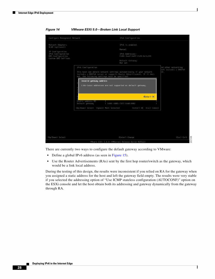
After rebooting the ESXi host, you need to define the addressing and default gateway. Since VMware vSphere 4.1, the ESX/ESXi hosts do not support the configuration of a link-local IPv6 address in the Default Gateway field. This is a very serious limitation and Cisco encourages you to work with VMware to get this limitation resolved as soon as possible. If you attempt to define a link local address, the system gives you an error as shown in Figure 14.
27Deploying IPv6 in the Internet Edge
Internet Edge IPv6 Deployment
Figure 14 VMware ESXi 5.0—Broken Link Local Support
There are currently two ways to configure the default gateway according to VMware:
• Define a global IPv6 address (as seen in Figure 15).
• Use the Router Advertisements (RAs) sent by the first hop router/switch as the gateway, which would be a link local address.
During the testing of this design, the results were inconsistent if you relied on RA for the gateway when you assigned a static address for the host and left the gateway field empty. The results were very stable if you selected the addressing option of “Use ICMP stateless configuration (AUTOCONF)” option on the ESXi console and let the host obtain both its addressing and gateway dynamically from the gateway through RA.
28Deploying IPv6 in the Internet Edge

Internet Edge IPv6 Deployment
Figure 15 VMware ESXi 5.0—Define A Static Global Address For The Gateway—Workaround
Once there is IPv6 connectivity on the ESXi hosts and the vCenter server running Windows Server 2008 or greater has IPv6 configured, you can use the VMware vSphere client to access the vCenter server (or hosts directly) over IPv6. You can use a DNS-registered name that has a DNS AAAA record for the vCenter server or just use the static IPv6 address of the server, as seen in Figure 16.
Figure 16 VMware vSphere 5.0—vSphere Client
29Deploying IPv6 in the Internet Edge

Internet Edge IPv6 Deployment
Figure 17 shows the “Add Host Wizard” screen where you can add a host through an IPv6 AAAA DNS name or through the IPv6 address.
Figure 17 VMware vSphere 5.0—Add Host Wizard
In this section we discussed a dual stack design that allows for IPv6 Web services to be delivered to IPv6-enabled clients on the Internet by dual stacking the links from the ISP through the edge routers peering over BGP, applying security services through the Cisco ASA and Cisco IPS, and providing application delivery services through the Cisco ACE. Connections can be made to IPv6-enabled hosts either running on baremetal servers or a virtualized platform such as VMware vSphere 4.1 and higher, Citrix XenServer (limited IPv6 support), or Microsoft Hyper-V with Microsoft Systems Center Virtual Machine Manager.
Server Load Balanced IPv6-to-IPv4 (SLB64)In the SLB64 design, everything that was previously discussed, including topology, addressing, and configuration up to the Cisco ACE, is identical. The SLB64 design is for those who need to allow IPv6 endpoints on the Internet to access content that is housed on IPv4-only servers or IPv4-only capable applications. In the scenario discussed in this document the enterprise can support IPv6 all the way from the ISP to the north side of the Cisco ACE. For some reason the enterprise cannot or does not want to deploy IPv6 all the way to the server farm. This could be due to the cost of upgrade for legacy operating systems, non-compliant applications, and resource constraints that prohibit proper testing and deployment of IPv6-capable operating systems and/or applications, or perhaps it is just a time factor. Whatever the reason, IPv6 cannot go end-to-end.
30Deploying IPv6 in the Internet Edge

Internet Edge IPv6 Deployment
The advantage of SLB64 over a design like NAT64 is that SLB64 adds two functions together, SLB and IPv6-to-IPv4 translation, whereas NAT64 only performs the translation part. The SLB component is very important as every customer that is deploying IPv6 in the Internet edge is doing so primarily (at least initially) to support Web content. You load-balance Web servers in a normal production environment, so integrating the SLB and translation at the same point in the network makes the most sense.
Figure 18 shows the high-level topology for the SLB64 design. Again, it is identical to that of the dual stack design with the exception that everything south of the Cisco ACE (server facing) is IPv4-only.
Figure 18 SLB64—High-Level Topology
2921
37
ISP-RTR-1
Services(ASA, IPS, ACE)
Dua
l Sta
ckIP
v4-o
nly
Servers
IE Routers
IE Outer Switches
IE Services Tier
- Web- App- DB- DNS
IE Inner Switches SLB64Boundary
IE Access Layer Nexus 5000
UCS
Nexus1000 VEM
Nexus1000 VSM
VMwareESX Hosts
ISP-RTR-2
EnterpriseCore
31Deploying IPv6 in the Internet Edge

Internet Edge IPv6 Deployment
The overall design considerations are identical to the dual stack design, except there is less to configure. Since the key element in the translation function is in the Cisco ACE, that is where we focus attention in this section.
Figure 19 shows the pertinent IPv6 and IPv4 addresses for this design.
Figure 19 SLB64—Addressing
We skip all of the configurations except for the Cisco ACE IE-WEB context. All configurations referenced in the dual stack section are identical. In the Cisco ACE configuration below, there is a probe defined, two rservers with IPv4 addresses, an IPv6-enabled VIP, and the same policy map information as was listed in the dual stack configuration. The primary configuration components for SLB64 are the north-facing VIP, which is IPv6, and the south-facing rservers and SNAT pool, which are all IPv4.
2921
28
VIP: 2001:DB8:CAFE:115::A
SNAT: 10.140.19.250
Cisco ACEOne-Arm Mode
IPv6-enabledClient
Web-0210.140.19.81
Web-0110.140.19.80
ISP-RTR-1
Dua
l Sta
ckIP
v4-o
nly
32Deploying IPv6 in the Internet Edge
Internet Edge IPv6 Deployment
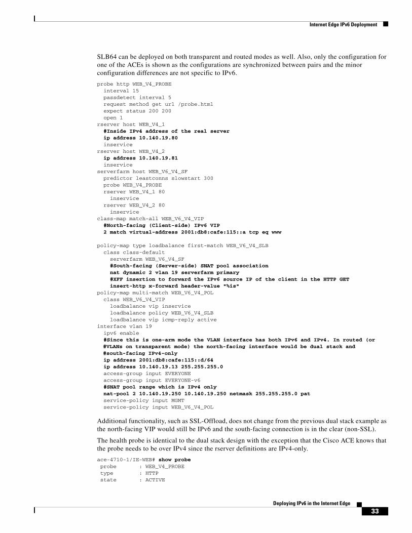
SLB64 can be deployed on both transparent and routed modes as well. Also, only the configuration for one of the ACEs is shown as the configurations are synchronized between pairs and the minor configuration differences are not specific to IPv6.
probe http WEB_V4_PROBE interval 15 passdetect interval 5 request method get url /probe.html expect status 200 200 open 1rserver host WEB_V4_1 #Inside IPv4 address of the real server ip address 10.140.19.80 inservicerserver host WEB_V4_2 ip address 10.140.19.81 inserviceserverfarm host WEB_V6_V4_SF predictor leastconns slowstart 300 probe WEB_V4_PROBE rserver WEB_V4_1 80 inservice rserver WEB_V4_2 80 inserviceclass-map match-all WEB_V6_V4_VIP #North-facing (Client-side) IPv6 VIP 2 match virtual-address 2001:db8:cafe:115::a tcp eq www
policy-map type loadbalance first-match WEB_V6_V4_SLB class class-default serverfarm WEB_V6_V4_SF #South-facing (Server-side) SNAT pool association nat dynamic 2 vlan 19 serverfarm primary #XFF insertion to forward the IPv6 source IP of the client in the HTTP GET insert-http x-forward header-value "%is"policy-map multi-match WEB_V6_V4_POL class WEB_V6_V4_VIP loadbalance vip inservice loadbalance policy WEB_V6_V4_SLB loadbalance vip icmp-reply activeinterface vlan 19 ipv6 enable #Since this is one-arm mode the VLAN interface has both IPv6 and IPv4. In routed (or#VLANs on transparent mode) the north-facing interface would be dual stack and#south-facing IPv4-only
ip address 2001:db8:cafe:115::d/64 ip address 10.140.19.13 255.255.255.0 access-group input EVERYONE access-group input EVERYONE-v6 #SNAT pool range which is IPv4 only nat-pool 2 10.140.19.250 10.140.19.250 netmask 255.255.255.0 pat service-policy input MGMT service-policy input WEB_V6_V4_POL
Additional functionality, such as SSL-Offload, does not change from the previous dual stack example as the north-facing VIP would still be IPv6 and the south-facing connection is in the clear (non-SSL).
The health probe is identical to the dual stack design with the exception that the Cisco ACE knows that the probe needs to be over IPv4 since the rserver definitions are IPv4-only.
ace-4710-1/IE-WEB# show probe probe : WEB_V4_PROBE type : HTTP state : ACTIVE
33Deploying IPv6 in the Internet Edge
Internet Edge IPv6 Deployment
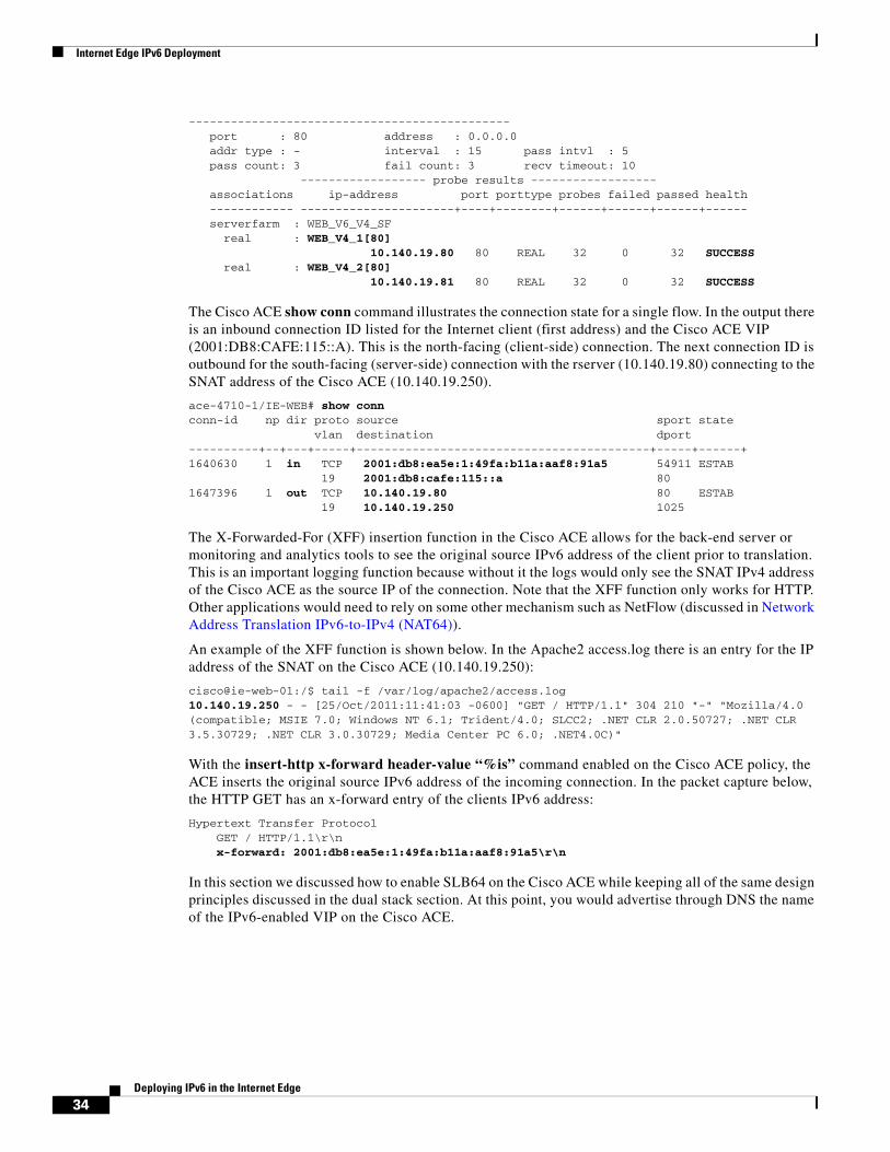
---------------------------------------------- port : 80 address : 0.0.0.0 addr type : - interval : 15 pass intvl : 5 pass count: 3 fail count: 3 recv timeout: 10 ------------------ probe results ------------------ associations ip-address port porttype probes failed passed health ------------ ----------------------+----+--------+------+------+------+------ serverfarm : WEB_V6_V4_SF real : WEB_V4_1[80] 10.140.19.80 80 REAL 32 0 32 SUCCESS real : WEB_V4_2[80] 10.140.19.81 80 REAL 32 0 32 SUCCESS
The Cisco ACE show conn command illustrates the connection state for a single flow. In the output there is an inbound connection ID listed for the Internet client (first address) and the Cisco ACE VIP (2001:DB8:CAFE:115::A). This is the north-facing (client-side) connection. The next connection ID is outbound for the south-facing (server-side) connection with the rserver (10.140.19.80) connecting to the SNAT address of the Cisco ACE (10.140.19.250).
ace-4710-1/IE-WEB# show connconn-id np dir proto source sport state vlan destination dport----------+--+---+-----+------------------------------------------+-----+------+1640630 1 in TCP 2001:db8:ea5e:1:49fa:b11a:aaf8:91a5 54911 ESTAB 19 2001:db8:cafe:115::a 801647396 1 out TCP 10.140.19.80 80 ESTAB 19 10.140.19.250 1025
The X-Forwarded-For (XFF) insertion function in the Cisco ACE allows for the back-end server or monitoring and analytics tools to see the original source IPv6 address of the client prior to translation. This is an important logging function because without it the logs would only see the SNAT IPv4 address of the Cisco ACE as the source IP of the connection. Note that the XFF function only works for HTTP. Other applications would need to rely on some other mechanism such as NetFlow (discussed in Network Address Translation IPv6-to-IPv4 (NAT64)).
An example of the XFF function is shown below. In the Apache2 access.log there is an entry for the IP address of the SNAT on the Cisco ACE (10.140.19.250):
cisco@ie-web-01:/$ tail -f /var/log/apache2/access.log10.140.19.250 - - [25/Oct/2011:11:41:03 -0600] "GET / HTTP/1.1" 304 210 "-" "Mozilla/4.0 (compatible; MSIE 7.0; Windows NT 6.1; Trident/4.0; SLCC2; .NET CLR 2.0.50727; .NET CLR 3.5.30729; .NET CLR 3.0.30729; Media Center PC 6.0; .NET4.0C)"
With the insert-http x-forward header-value “%is” command enabled on the Cisco ACE policy, the ACE inserts the original source IPv6 address of the incoming connection. In the packet capture below, the HTTP GET has an x-forward entry of the clients IPv6 address:
Hypertext Transfer Protocol GET / HTTP/1.1\r\n x-forward: 2001:db8:ea5e:1:49fa:b11a:aaf8:91a5\r\n
In this section we discussed how to enable SLB64 on the Cisco ACE while keeping all of the same design principles discussed in the dual stack section. At this point, you would advertise through DNS the name of the IPv6-enabled VIP on the Cisco ACE.
34Deploying IPv6 in the Internet Edge

Internet Edge IPv6 Deployment
Network Address Translation IPv6-to-IPv4 (NAT64)There are two different forms of NAT64, Stateless and Stateful. Stateless NAT64 is outside the scope of this document, as it really has no place in the enterprise Internet edge for the purpose of accessing enterprise-hosted content. Stateful NAT64 is the focus in this section. For more information on Stateless NAT64 and the RFCs for both Stateless NAT64 and Stateful NAT64, see:
• RFC6144 Framework for IPv4/IPv6 Translationhttp://www.ietf.org/rfc/rfc6144.txt
• RFC6052 IPv6 Addressing of IPv4/IPv6 Translatorshttp://www.ietf.org/rfc/rfc6052.txt
• RFC6145 IP/ICMP Translation Algorithm (Stateless NAT64)http://www.ietf.org/rfc/rfc6145.txt
• RFC6146 Stateful NAT64: Network Address and Protocol Translation from IPv6 Clients and IPv4 Servershttp://www.ietf.org/rfc/rfc6146.txt
• RFC6147 DNS64: DNS Extensions for Network Address Translation from IPv6 Clients to IPv4 Servershttp://www.ietf.org/rfc/rfc6147.txt
The theory and implementation for a wide variety of the Stateful NAT64 designs can be found in:
NAT64 Technology: Connecting IPv6 and IPv4 Networkshttp://www.cisco.com/en/US/prod/collateral/iosswrel/ps6537/ps6553/white_paper_c11-676278.html
The Cisco implementation of Stateful NAT64 is quite powerful and offers many implementation use cases, including:
• PAT/Overload
• Dynamic 1:1
• Static IPv6-to-IPv4
• Static IPv6-to-IPv4 with ports
• Static IPv4-to-IPv6
• Static IPv4-to-IPv6 with ports
Some of the key features and considerations of Stateful NAT64 include:
• Support of TCP, UDP, and ICMP
• IPv6 host address translated statefully through normal NAT mechanism
• IPv4 host address translated using either Well Known Prefix (WKP) or configured stateful prefix
• Dynamic Stateful NAT64 is dependent on DNS64 implementation
• Static Stateful NAT64 is not dependent on DNS64 implementation
The various use cases and detailed Cisco implementation of NAT64 can be found in the white paper referenced earlier (NAT64 Technology: Connecting IPv6 and IPv4 Networks). In this section the focus is on using Stateful NAT64 to connect dual stack clients on the Internet to IPv4-hosted content in the enterprise Internet edge. The mappings for the IPv4 servers are static and therefore no DNS64 implementation is needed and the IPv6-enabled clients can use standard DNS mechanisms to query IPv6-enabled DNS servers to resolve the AAAA record (or other record type) for the host.
35Deploying IPv6 in the Internet Edge
Internet Edge IPv6 Deployment
The primary reasons for using Stateful NAT64 instead of the full dual stack design are the exact same as for using SLB64. The difference is that you may not have a Cisco ACE or other load balancer on which to perform SLB64. If you have an existing investment in an application delivery controller now and it does not support IPv6 and you cannot afford to replace the HW or upgrade the SW, then Stateful NAT64 is an option. However, the same issue applies with NAT64 functionality in your current routing products. If your current routing infrastructure does not support NAT64, then an incremental capital expenditure has to be made and you have to decide if that is going to be in a new routing platform, such as the Cisco ASR 1000 series, or in a new application delivery controller, usch as the Cisco ACE. Either way, if you do not own it now, you will have to buy one or the other to handle your IPv6-to-IPv4 translation requirements.
Figure 20 shows the high-level topology of the NAT64 design. Note that it looks nearly identical to the SLB64 design with the exception of a new pair of Cisco ASR 1000 series routers. In Figure 20 the placement of the Cisco ASRs running the Stateful NAT64 feature is in a dual-arm connection to the inner switches. This allows for dual stack support from the ISP all the way to the north-facing (client-side) interface of the Cisco ASR 1000 series routers. Alternatively, the Cisco ASR 1000 series routers could be acting as the enterprise Internet edge routers that peer with the ISP and the Stateful NAT64 feature can be enabled there. In this case, only IPv6 would be deployed on the links between the ISP and the outside interfaces of the Cisco ASR.
36Deploying IPv6 in the Internet Edge

Internet Edge IPv6 Deployment
Figure 20 Stateful NAT64—High-Level Topology
Figure 21 shows the IPv6 and IPv4 addressing layout for the Stateful NAT64 design.
2921
39
ISP-RTR-1
Services(NAT64, ASA,
IPS, ACE)
Dua
l Sta
ckIP
v4-o
nly
Servers
IE Routers
IE Outer Switches
IE Services Tier
- Web- App- DB- DNS
IE Inner Switches
IE Access Layer Nexus 5000
UCS
Nexus1000 VEM
Nexus1000 VSM
VMwareESX Hosts
ISP-RTR-2
EnterpriseCore
QFP QFPNAT64Boundary
37Deploying IPv6 in the Internet Edge

Internet Edge IPv6 Deployment
Figure 21 Stateful NAT64—Addressing
The Stateful NAT64 configuration is not all that different from traditional NAT44 on Cisco IOS. In this setup the G0/0/2 interface is the north-facing (client-side) interface and the G0/0/3 interface is the south-facing (server-side) interface. Notice that IPv6 is only enabled on the G0/0/2 interface and IPv4 only on the G0/0/3 interface. You also can deploy this in a one arm scenario just like on the Cisco ACE. NAT64 is enabled on both interfaces. An ACL is defined to permit NAT64 processing for the two statically defined IPv6 addresses that represent that real IPv4-only configured Web servers. The static mapping between the outside IPv6 addresses and inside IPv4 addresses are:
• 2001:DB8:CAFE:BEEF::10 <> 10.140.19.80
• 2001:DB8:CAFE:BEEF::11 <> 10.140.19.81
2921
40
G0/0/2: 2001:DB8:CAFE:110::A/64
G0/0/3: 10.140.15.10/24
Cisco ASR 1000
IPv6-enabledClient
Web-0210.140.19.81
Web-0110.140.19.80
ISP-RTR-1
Dua
l Sta
ckIP
v4-o
nly
QFP G0/0/3
G0/0/2
38Deploying IPv6 in the Internet Edge

Internet Edge IPv6 Deployment
The IPv6 addresses must be out of the NAT64 stateful prefix, which in this case is 2001:DB8:CAFE:BEEF::/96. A /96 is used here as it maps to a 32-bit address range (128-32=96). You can use a different sized prefix.
An IPv4 pool is defined and is used for connections between the NAT64 process and the inside IPv4 servers. This is basically like the SNAT address previously discussed in Server Load Balanced IPv6-to-IPv4 (SLB64).
Finally, routing is configured for both IPv6 and IPv4. If the next-hop interface north-facing was capable of a dynamic IPv6 routing protocol (like OSPFv3 or EIGRPv6), then no static route is needed on the NAT64 gateway. In our case the Cisco ASA is the next-hop and it does not yet support a dynamic IPv6 routing protocol. EIGRP or OSPF for IPv4 can be used for the south-facing interfaces, which is used for routing throughout the enterprise topology. You must have a route in the network pointing to the NAT64 gateway for the Stateful NAT64 prefix or nothing will work. Again, this could be learned dynamically from the NAT64 gateway, but in our case that is not available given the next-hop is the firewall. On the Cisco ASA a static route is added for the Stateful NAT64 prefix (for more on this, see the configuration for the Cisco ASA immediately following this configuration example).
ipv6 unicast-routing!interface GigabitEthernet0/0/2 description to 6k-inner-1 Outside no ip address ipv6 address 2001:DB8:CAFE:110::A/64 nat64 enable!interface GigabitEthernet0/0/3 description to 6k-inner-1 Inside ip address 10.140.15.10 255.255.255.0 nat64 enable!ipv6 access-list EDGE_ACL permit ipv6 any host 2001:DB8:CAFE:BEEF::10 permit ipv6 any host 2001:DB8:CAFE:BEEF::11!nat64 prefix stateful 2001:DB8:CAFE:BEEF::/96nat64 v4 pool IE 10.140.15.20 10.140.15.20nat64 v4v6 static 10.140.19.80 2001:DB8:CAFE:BEEF::10nat64 v4v6 static 10.140.19.81 2001:DB8:CAFE:BEEF::11nat64 v6v4 list EDGE_ACL pool IE overload!ipv6 route ::/0 2001:DB8:CAFE:110::10
router eigrp 10 network 10.0.0.0
The following configuration is for the Cisco ASA. The outside interface configuration is identical to that shown in Dual Stack. The Cisco ASAs have trunked links on the inside and below is the sub-interface for the NAT64 link. G0/1.14 with VLAN 14 connects the north-facing interface (G0/0/2) of the Cisco ASR. The Cisco ASA has a default route for IPv6 pointing to the Internet edge routers, as before, but has a new static route for the Stateful NAT64 prefix (2001:DB8:CAFE:BEEF::/96) that points to the Cisco ASR G0/0/2 IPv6 address. This is a must to properly route traffic that is going to be translated to the NAT64 process on the Cisco ASR.
The Cisco ASA has an object definition for each IPv6 address that is used in the static translation (remember that the Cisco ASA only sees the IPv6 side of the connection). ACLs are defined for the objects and applied to the outside interface.
interface GigabitEthernet0/0 nameif outside security-level 0
39Deploying IPv6 in the Internet Edge

Internet Edge IPv6 Deployment
ipv6 address 2001:db8:cafe:103::3/64 standby 2001:db8:cafe:103::4!interface GigabitEthernet0/1.14 vlan 14 nameif nat64 security-level 50 ipv6 address 2001:db8:cafe:110::10/64 standby 2001:db8:cafe:110::11 ipv6 enable ipv6 nd suppress-ra!ipv6 route outside ::/0 fe80::5:73ff:fea0:2ipv6 route nat64 2001:db8:cafe:beef::/96 2001:db8:cafe:110::a !object network NAT64-WEB-01 host 2001:db8:cafe:beef::10object network NAT64-WEB-02 host 2001:db8:cafe:beef::11!ipv6 access-list outside_access_ipv6_in permit tcp any object NAT64-WEB-01 eq wwwipv6 access-list outside_access_ipv6_in permit tcp any object NAT64-WEB-02 eq www!access-group outside_access_ipv6_in in interface outside
Using show nat64 translations on the Cisco ASR 1000 series router displays the static translations as well as dynamic translations. The output below shows the two static 1:1 IPv6-to-IPv4 translations as well as a dynamic translation for an incoming client connection (2001:db8:ea5e:1:49fa:b11a:aaf8:91a5) to the IPv6 static address (2001:db8:cafe:beef::10) on port 80. The IPv4 translation details show the connection between the IPv4 address of the Web server and the NAT64 pool address of 10.140.15.20.
asr1k-1#show nat64 translationsProto Original IPv4 Translated IPv4 Translated IPv6 Original IPv6------------------------------------------------------------------------------- 10.140.19.81 2001:db8:cafe:beef::11 --- ------ 10.140.19.80 2001:db8:cafe:beef::10 --- ---tcp 10.140.19.80:80 [2001:db8:cafe:beef::10]:80 10.140.15.20:1024 [2001:db8:ea5e:1:49fa:b11a:aaf8:91a5]:57316
As was discussed in Server Load Balanced IPv6-to-IPv4 (SLB64) and the information there about XFF, you must ensure that back-end systems can log the original source IPv6 address of incoming connections. Cisco IOS does not support the XFF insertion like the Cisco ACE does. This is a challenge for environments that already have Web analytics and geolocation services that use XFF. The NAT64 model without XFF can be limiting and less viable if you already leverage XFF. However, Cisco IOS NetFlow can be used to accomplish a similar result.
The Cisco IOS NetFlow Export function and, specifically, the “IPv6 original-input flow” record can provide a lot of information about the incoming connection.
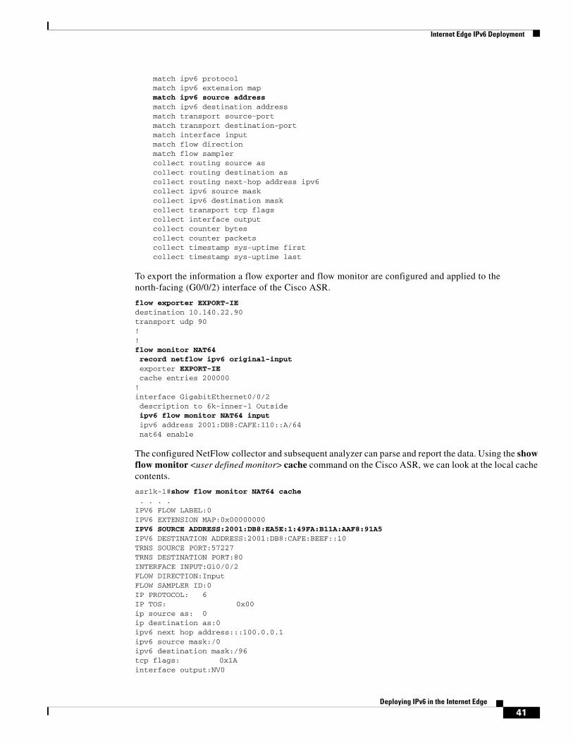
Using the show flow record netflow ipv6 original-input command, we can see all of the information that can be matched on and exported. The specific field we are looking to export in our design is the match ipv6 source address field.
asr1k-1#show flow record netflow ipv6 original-inputflow record netflow ipv6 original-input: Description: Traditional IPv6 input NetFlow with ASs No. of users: 0 Total field space: 97 bytes Fields: match ipv6 traffic-class match ipv6 flow-label
40Deploying IPv6 in the Internet Edge
Internet Edge IPv6 Deployment
match ipv6 protocol match ipv6 extension map match ipv6 source address match ipv6 destination address match transport source-port match transport destination-port match interface input match flow direction match flow sampler collect routing source as collect routing destination as collect routing next-hop address ipv6 collect ipv6 source mask collect ipv6 destination mask collect transport tcp flags collect interface output collect counter bytes collect counter packets collect timestamp sys-uptime first collect timestamp sys-uptime last
To export the information a flow exporter and flow monitor are configured and applied to the north-facing (G0/0/2) interface of the Cisco ASR.
flow exporter EXPORT-IE destination 10.140.22.90transport udp 90!!flow monitor NAT64 record netflow ipv6 original-input exporter EXPORT-IE cache entries 200000!interface GigabitEthernet0/0/2 description to 6k-inner-1 Outside ipv6 flow monitor NAT64 input ipv6 address 2001:DB8:CAFE:110::A/64 nat64 enable
The configured NetFlow collector and subsequent analyzer can parse and report the data. Using the show flow monitor <user defined monitor> cache command on the Cisco ASR, we can look at the local cache contents.
asr1k-1#show flow monitor NAT64 cache . . . .IPV6 FLOW LABEL:0IPV6 EXTENSION MAP:0x00000000IPV6 SOURCE ADDRESS:2001:DB8:EA5E:1:49FA:B11A:AAF8:91A5 IPV6 DESTINATION ADDRESS:2001:DB8:CAFE:BEEF::10TRNS SOURCE PORT:57227TRNS DESTINATION PORT:80INTERFACE INPUT:Gi0/0/2FLOW DIRECTION:InputFLOW SAMPLER ID:0IP PROTOCOL: 6IP TOS: 0x00ip source as: 0ip destination as:0ipv6 next hop address:::100.0.0.1ipv6 source mask:/0ipv6 destination mask:/96tcp flags: 0x1Ainterface output:NV0
41Deploying IPv6 in the Internet Edge

Internet Edge IPv6 Deployment
counter bytes: 661counter packets:4timestamp first:13:21:37.815timestamp last:13:21:38.039
In this section, a Stateful NAT64 deployment was enabled to allow for IPv6 access from the ISP to the north-facing side of the Cisco ASR 1000 series router where static translation occurred between the IPv6 side of the router to the IPv4-only side of the router where the IPv4-only Web servers reside.
Locator/ID Separation Protocol (LISP)LISP is a next-generation routing architecture that is protocol agnostic in that it works equally with IPv4 and IPv6. LISP is a unique case of a tunnel-based approach, but unlike manually configured tunnels, GRE, and other encapsulation types, it is dynamic and, most importantly, requires no preconfiguration of tunnel information at each tunnel endpoint.
LISP is ideal in multi-homed configurations and provides support for LISP-to-LISP and LISP-to-non-LISP site connections. Some of the advantages of LISP include rapid deployment, low-to-no cost, and high performance. In the context of IPv6 deployment, LISP allows an enterprise to communicate with other IPv6 sites or users (LISP or non-LISP connected) when their ISP does not offer native IPv6 support at the Internet edge.
Until now, this document has focused on deployment when an ISP can offer IPv6 support to the Internet edge routers. In this section we are going to approach the design with a scenario where the ISP only offers IPv4, but yet the enterprise needs to have IPv6 reachability of its content in the Internet edge. We leverage LISP at the Internet edge routers to facilitate this connectivity.
While LISP theory and exhaustive architecture review is outside the scope of this document, it is important to define a few roles and acronyms associated with LISP.
LISP Site Devices
• Ingress Tunnel Router (ITR)—An ITR is a LISP site edge device that receives packets from site-facing interfaces (internal hosts) and encapsulates them to remote LISP sites or natively forwards them to non-LISP sites.
• Egress Tunnel Router (ETR)—An ETR is a LISP site edge device that receives packets from core-facing interfaces (the Internet) and decapsulates LISP packets and delivers them to local EIDs at the site.
• xTR is used to refer to a customer edge (CE) device that implements both ITR and ETR functions at the same time (which is typical).
LISP Infrastructure Devices
• Map-Server (MS)—An MS is a LISP infrastructure device that LISP site ETRs register to with their EID (Endpoint Identifier) prefixes. The MS advertises aggregates for the registered EID prefixes into the LISP mapping system. All LISP sites use the LISP mapping system to resolve EID-to-RLOC (Routing Locators) mappings.
• Map-Resolver (MR)—An MR is a LISP infrastructure device to which LISP site ITRs send LISP Map-Request queries when resolving EID-to-RLOC mappings.
42Deploying IPv6 in the Internet Edge

Internet Edge IPv6 Deployment
• Proxy ITR (PITR)—A PITR is a LISP infrastructure device that provides connectivity between non-LISP sites and LISP sites by attracting non-LISP traffic destined to LISP sites and encapsulating this traffic to LISP sites. In the IPv6 deployment case, the PITR can attract IPv6 non-LISP traffic and forward it to a LISP site using IPv4 as the transport.
• Proxy ETR (PETR)—A PETR is a LISP infrastructure device that allows IPv6 LISP sites to have only IPv4 RLOC connectivity to reach non-LISP sites that have only IPv6 RLOC connectivity.
• PxTR is used to refer to a device that implements both PITR and PETR functionality.
A critical concept in LISP is the separation of namespaces, which is a new semantic for IP addressing. The two namespaces used are the Endpoint Identifier (EID), which are current addresses assigned to end-hosts and Routing Locators (RLOCs), which are addresses assigned to devices, such as routers, that make up the global routing system. The EID addresses go into DNS records as usual.
There is much more information that you need to gather and learn to be able to successfully understand the functional architecture and design of LISP. Detailed information on the theory, operation, and deployment of LISP for multiple use cases can be found at the following sites (accessible through both IPv4 and IPv6):
• http://lisp.cisco.com/
• http://www.lisp4.net/
• http://www.lisp6.net/
The design scenario in this document is shown at a high-level in Figure 22. The Internet edge routers are deployed as xTRs (ITR/ETR). They use public MR and MS infrastructure devices for mapping resolution and registration. When a non-LISP site or user needs to communicate with the enterprise site, it is routed to the public PxTR (PITR/PETR) infrastructure devices for encapsulation to the xTR site routers (indicated in black solid lines between the xTRs and PxTR). If another LISP site needs to communicate with the LISP-enabled enterprise site, it simply uses the public MR/MS infrastructure devices to resolve the mapping request and then establishes a direct (encapsulated) connection from its own xTRs to the enterprise sites xTRs (indicated by the dashed black line between the “LISP Enabled Site” and the xTRs).
Everything behind the enterprise xTRs is dual stack-enabled in our scenario so everything previously discussed in the Dual Stack applies. The only difference between the full dual stack option and this LISP option is that the IPv6 traffic ingress and egress for the site is using LISP and not a dual stack connection natively on the ISP-to-CE links. Alternatively, LISP can be combined with the SLB64 or NAT64 options previously discussed.
43Deploying IPv6 in the Internet Edge

Internet Edge IPv6 Deployment
Figure 22 LISP High-Level Topology
Since this is an enterprise-focused CVD, only the configurations for the xTRs are shown as the MR/MS and PxTR are service provider supplied roles. Check the previous links for the current list of provider hosted LISP infrastructure device that you can leverage for your LISP deployment.
2921
41
Services(ASA, IPS, ACE)
Dua
l Sta
ck
Servers
xTRxTR
IE Routers
IE Outer Switches
IE Services Tier
- Web- App- DB- DNS
IE Inner Switches
IE Access Layer Nexus 5000
UCS
Nexus1000 VEM
Nexus1000 VSM
VMwareESX Hosts
IPv4Internet IPv6
Internet
MR/MSPxTR
Non-LISP EnabledSite/User
LISP EnabledSite
44Deploying IPv6 in the Internet Edge
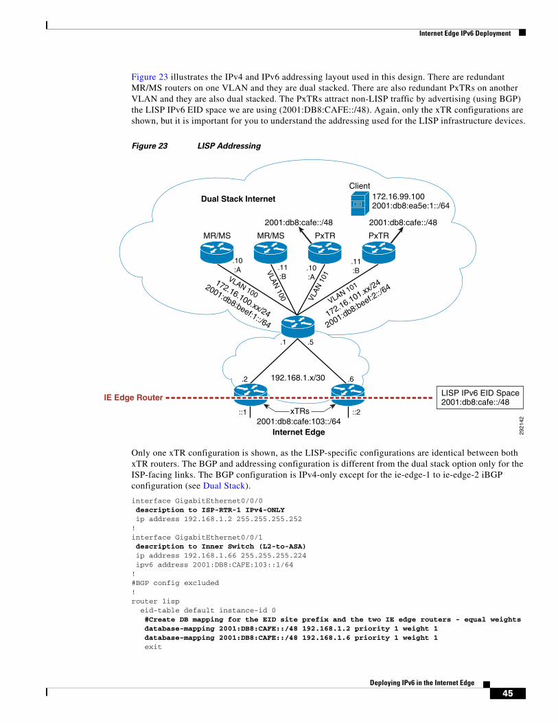
Internet Edge IPv6 Deployment
Figure 23 illustrates the IPv4 and IPv6 addressing layout used in this design. There are redundant MR/MS routers on one VLAN and they are dual stacked. There are also redundant PxTRs on another VLAN and they are also dual stacked. The PxTRs attract non-LISP traffic by advertising (using BGP) the LISP IPv6 EID space we are using (2001:DB8:CAFE::/48). Again, only the xTR configurations are shown, but it is important for you to understand the addressing used for the LISP infrastructure devices.
Figure 23 LISP Addressing
Only one xTR configuration is shown, as the LISP-specific configurations are identical between both xTR routers. The BGP and addressing configuration is different from the dual stack option only for the ISP-facing links. The BGP configuration is IPv4-only except for the ie-edge-1 to ie-edge-2 iBGP configuration (see Dual Stack).
interface GigabitEthernet0/0/0 description to ISP-RTR-1 IPv4-ONLY ip address 192.168.1.2 255.255.255.252!interface GigabitEthernet0/0/1 description to Inner Switch (L2-to-ASA) ip address 192.168.1.66 255.255.255.224 ipv6 address 2001:DB8:CAFE:103::1/64!#BGP config excluded!router lisp eid-table default instance-id 0 #Create DB mapping for the EID site prefix and the two IE edge routers - equal weights database-mapping 2001:DB8:CAFE::/48 192.168.1.2 priority 1 weight 1 database-mapping 2001:DB8:CAFE::/48 192.168.1.6 priority 1 weight 1 exit
2921
42
192.168.1.x/30
172.16.101.xx/24
2001:db8:beef:2::/6
4
2001:db8:cafe:103::/64
2001:db8:cafe::/48 2001:db8:cafe::/48
172.16.99.1002001:db8:ea5e:1::/64
MR/MS
Dual Stack Internet
Client
MR/MS
xTRs
PxTR PxTR
Internet Edge
.6
::2::1
.2
.5
.11:B
.10:A .11
:B.10:A
VLAN 101
VLAN
101
VLA
N 100
172.16.100.xx/24
2001:db8:beef:1::/64
VLAN 100
.1
LISP IPv6 EID Space2001:db8:cafe::/48IE Edge Router
45Deploying IPv6 in the Internet Edge

Internet Edge IPv6 Deployment
! #Use two PETRs ipv6 use-petr 172.16.101.10 ipv6 use-petr 172.16.101.11 #Use two Map Resolvers ipv6 itr map-resolver 172.16.100.10 ipv6 itr map-resolver 172.16.100.11 #Act as an ITR ipv6 itr #Use two Map Servers ipv6 etr map-server 172.16.100.10 key CISCO ipv6 etr map-server 172.16.100.11 key CISCO #Act as an ETR ipv6 etr exit!#Create a null default route, which LISP will use ipv6 route ::/0 Null0
Once the configuration is complete and we test with a connection between the site and a client on the Internet, the map-caches are populated on the relevant devices. Below the xTR (ie-edge-1) has a map-cache entry with the coarse aggregate route that includes the prefix the client resides on (2001:DB8:EA5E:1::/64) and the aggregate map-cache created is 2001:DB8:E000::/35. The client is just an IPv6-enabled host on the Internet and not a LISP site, so the PxTR role is used to encapsulate between the xTR and PxTR devices, which then forward to the client natively using IPv6.
ie-edge-1#show ipv6 lisp map-cacheLISP IPv6 Mapping Cache for EID-table default (IID 0), 2 entries::/0, uptime: 01:01:55, expires: never, via static send map-request Negative cache entry, action: send-map-request2001:DB8:E000::/35, uptime: 00:58:48, expires: 00:00:44, via map-reply, forward-native Encapsulating to proxy ETR
On the MR/MS device there is a site registration for this customer:
On the PxTR device there are two locators (for each xTR) listed for the EID prefix listed in the map-cache:
PxTR-1#show ipv6 lisp map-cacheLISP IPv6 Mapping Cache for EID-table default (IID 0), 1 entries2001:DB8:CAFE::/48, uptime: 00:55:53, expires: 23:04:52, via map-reply, complete Locator Uptime State Pri/Wgt 192.168.1.2 00:55:00 up 1/1 192.168.1.6 00:55:00 up 1/1
Internal IPv6 hosts can now egress through the xTRs using LISP encapsulation natively to other LISP sites using the MR/MS roles and they can also communicate with non-LISP sites using the PxTR roles. The reverse process works for external LISP and non-LISP sites or individual hosts establishing communications with IPv6-enabled hosts at the enterprise Internet edge.
46Deploying IPv6 in the Internet Edge

Conclusion
ConclusionIn this CVD we have looked at four options for configuring the enterprise Internet edge to support access to IPv6-enabled content to Internet users. The four options discussed were:
• Full Dual Stack
• SLB64
• Stateful NAT64
• LISP
The configurations, while simplistic, offer a baseline for you to build upon in your unique environment. Your long-term goal must always be a dual stack design, but there are conditions, use cases, and drivers where that may not be possible. The SLB64, Stateful NAT64, and LISP options can be leveraged when an alternative is needed.
Table 2 summarizes the benefits and challenges with each of the models discussed in this document and can be used to help facilitate a discussion within your organization.
Table 2 Benefits and Challenges of Various Models
Model Benefit Challenge
Dual-stack (DS) No tunneling required.
No translation required.
No dependency on IPv4 (routing, QoS, HA, multicast, security, and management are separated).
Superior performance, scalability, and highest availability for IPv6 traffic.
Offers native visibility into IPv6 for security and management purposes versus translation or tunneling approaches.
Requires IPv6 support in all Layer 3 or above aware platforms.
47Deploying IPv6 in the Internet Edge

Conclusion
SLB64 Allows for IPv6 access to IPv4-only servers and applications while at the same time providing integrated application delivery services such as SLB, SSL-Offload, and others.
Removes immediate need to dual stack or enable IPv6 on server operating systems and/or applications.
Higher performance and availability over design choices such as software-only reverse proxies.
High availability leveraging the HA functions in the Cisco ACE.
Leverage existing SLB platform if using the Cisco ACE 4710 Appliance or Cisco ACE 30 Service Module.
Non-disruptive to existing IPv4 configuration or applications.
Maintain source IPv6 visibility with XFF insertion.
Still requires IPv6 from the ISP all the way to the north-facing (Client side) of the Cisco ACE.
Potential cost associated with the purchase of IPv6-supported Cisco ACE hardware (if running Cisco ACE 10 or 20 Service modules).
Does not currently support every application type or protocol today.
Performance may not match a pure dual stack design depending on the traffic rates for IPv6 in the enterprise.
Table 2 Benefits and Challenges of Various Models
48Deploying IPv6 in the Internet Edge
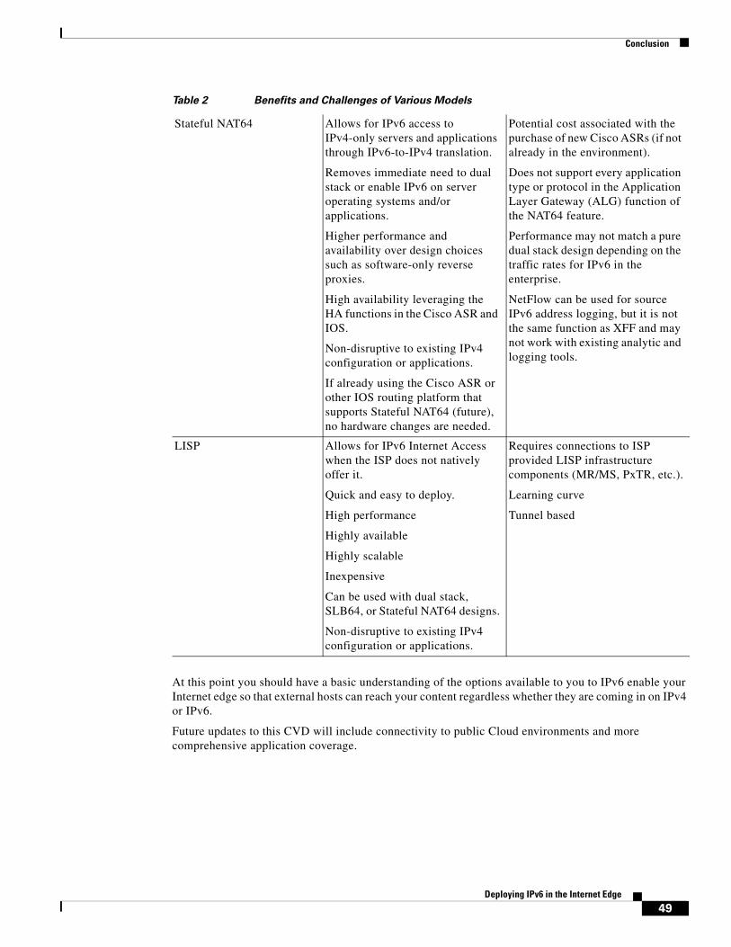
Conclusion
At this point you should have a basic understanding of the options available to you to IPv6 enable your Internet edge so that external hosts can reach your content regardless whether they are coming in on IPv4 or IPv6.
Future updates to this CVD will include connectivity to public Cloud environments and more comprehensive application coverage.
Stateful NAT64 Allows for IPv6 access to IPv4-only servers and applications through IPv6-to-IPv4 translation.
Removes immediate need to dual stack or enable IPv6 on server operating systems and/or applications.
Higher performance and availability over design choices such as software-only reverse proxies.
High availability leveraging the HA functions in the Cisco ASR and IOS.
Non-disruptive to existing IPv4 configuration or applications.
If already using the Cisco ASR or other IOS routing platform that supports Stateful NAT64 (future), no hardware changes are needed.
Potential cost associated with the purchase of new Cisco ASRs (if not already in the environment).
Does not support every application type or protocol in the Application Layer Gateway (ALG) function of the NAT64 feature.
Performance may not match a pure dual stack design depending on the traffic rates for IPv6 in the enterprise.
NetFlow can be used for source IPv6 address logging, but it is not the same function as XFF and may not work with existing analytic and logging tools.
LISP Allows for IPv6 Internet Access when the ISP does not natively offer it.
Quick and easy to deploy.
High performance
Highly available
Highly scalable
Inexpensive
Can be used with dual stack, SLB64, or Stateful NAT64 designs.
Non-disruptive to existing IPv4 configuration or applications.
Requires connections to ISP provided LISP infrastructure components (MR/MS, PxTR, etc.).
Learning curve
Tunnel based
Table 2 Benefits and Challenges of Various Models
49Deploying IPv6 in the Internet Edge

Additional References
Additional ReferencesMany notes and disclaimers in this document discuss the need to fully understand the technology and protocol aspects of IPv6 and the mechanisms for deployment. There are many design considerations associated with the implementation of IPv6 that include security, availability, management, IT training, and application support.
The following references—Cisco-specific and industry links—are a few of the many that provide more details on IPv6, Cisco design recommendations, products and solutions, and industry activity.
• Deploying IPv6 in Campus Networks (CVD)http://www.cisco.com/en/US/docs/solutions/Enterprise/Campus/CampIPv6.html
• Deploying IPv6 in Branch Networks (CVD)http://www.cisco.com/en/US/docs/solutions/Enterprise/Branch/BrchIPv6.html
• IPv6 in Enterprise Networks by Shannon McFarland, Muninder Sambi, Nikhil Sharma, Sanjay Hooda (ISBN-10:1-58714-227-9; ISBN-13: 978-1-58714-227-7)http://www.ciscopress.com/bookstore/product.asp?isbn=1587142279
• Deploying IPv6 Networks by Ciprian P. Popoviciu, Eric Levy-Abegnoli, Patrick Grossetete (ISBN-10:1-58705-210-5; ISBN-13:978-1-58705-210-1)http://www.ciscopress.com/bookstore/product.asp?isbn=1587052105&rl=1
• IPv6 Security by Scott Hogg, Eric Vyncke (ISBN-10:1-58705-594-5; ISBN-13: 978-1-58705-594-2)http://www.ciscopress.com/bookstore/product.asp?isbn=1587055945
• Cisco IPv6http://www.cisco.com/en/US/products/ps6553/products_ios_technology_home.html
• Cisco Design Zonehttp://www.cisco.com/en/US/netsol/ns742/networking_solutions_program_category_home.html
• Cisco IOS IPv6 Documentation for 15.2http://www.cisco.com/en/US/docs/ios-xml/ios/ipv6/configuration/15-2mt/ipv6-15-2mt-book.html
• Cisco ASA 8.4 Documentationhttp://www.cisco.com/en/US/docs/security/asa/asa84/configuration/guide/asa_84_cli_config.html
• Cisco IPS 4200 version 7.1 Documentationhttp://www.cisco.com/en/US/docs/security/ips/7.1/configuration/guide/idm/idmguide71.html
• Cisco ACE 4710 Configuration Guide Indexhttp://www.cisco.com/en/US/products/ps7027/products_installation_and_configuration_guides_list.html
• Cisco Nexus 5000 Configuration Guide Indexhttp://www.cisco.com/en/US/products/ps9670/products_installation_and_configuration_guides_list.html
• Cisco Nexus 1000V Configuration Guide Indexhttp://www.cisco.com/en/US/products/ps9902/products_installation_and_configuration_guides_list.html
• Catalyst 6500 Switch Software Configuration Guide, Release 12.2(SX)http://www.cisco.com/en/US/docs/switches/lan/catalyst6500/ios/12.2SX/configuration/guide/book.html
• Cisco LISPhttp://lisp.cisco.com/
50Deploying IPv6 in the Internet Edge

Additional References
• VMware vSphere 5.0 Documentationhttp://www.vmware.com/support/pubs/vsphere-esxi-vcenter-server-pubs.html
• ARIN IPv6https://www.arin.net/policy/nrpm.html
• AfriNIC IPv6http://www.afrinic.net/IPv6/
• APNIC IPv6http://www.apnic.net/policy/ipv6-address-policy
• LACNIC IPv6http://lacnic.net/en/politicas/ipv6.html
• RIPE IPv6http://www.ripe.net/ripe/docs/ripe-523
51Deploying IPv6 in the Internet Edge


