104


Deploying MPLS-based IP VPNs
Rajiv Asati, Distinguished Engineer, Cisco
BRKMPL-2102
Rajiv_cisco

© 2016 Cisco and/or its affiliates. All rights reserved. Cisco Public
Abstract
• This session describes the implementation of IP Virtual Private Networks (IP VPNs) using MPLS. It is the most common Layer 3 VPN technology, as standardized by IETF RFC2547/4364, realizing IP connectivity between VPNsite and MPLS network.
• Service Providers have been using IP VPN to provide scalable site-to-site/WAN connectivity to Enterprises/SMBs’ for more than a decade. Enterprises have been using it to address network segmentation (virtualization and traffic separation) inside the site e.g. Campus, Data Center. This technology realizes IP connectivity between VPN site and MPLS network.
• The session will cover: • IP VPN Technology Overview (RFC2547/RFC4364)• IP VPN Configuration Overview• IP VPN Deployment Scenarios• IP VPN Use-Cases• Best Practices
BRKMPL-2102 3
© 2016 Cisco and/or its affiliates. All rights reserved. Cisco Public
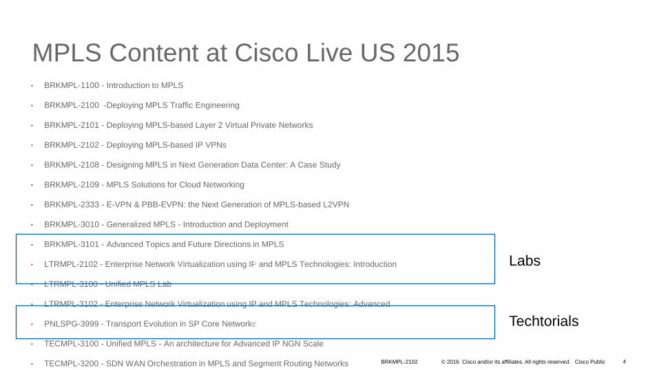
MPLS Content at Cisco Live US 2015• BRKMPL-1100 - Introduction to MPLS
• BRKMPL-2100 -Deploying MPLS Traffic Engineering
• BRKMPL-2101 - Deploying MPLS-based Layer 2 Virtual Private Networks
• BRKMPL-2102 - Deploying MPLS-based IP VPNs
• BRKMPL-2108 - Designing MPLS in Next Generation Data Center: A Case Study
• BRKMPL-2109 - MPLS Solutions for Cloud Networking
• BRKMPL-2333 - E-VPN & PBB-EVPN: the Next Generation of MPLS-based L2VPN
• BRKMPL-3010 - Generalized MPLS - Introduction and Deployment
• BRKMPL-3101 - Advanced Topics and Future Directions in MPLS
• LTRMPL-2102 - Enterprise Network Virtualization using IP and MPLS Technologies: Introduction
• LTRMPL-3100 - Unified MPLS Lab
• LTRMPL-3102 - Enterprise Network Virtualization using IP and MPLS Technologies: Advanced
• PNLSPG-3999 - Transport Evolution in SP Core Networks
• TECMPL-3100 - Unified MPLS - An architecture for Advanced IP NGN Scale
• TECMPL-3200 - SDN WAN Orchestration in MPLS and Segment Routing Networks
v
v Labs
Techtorials
BRKMPL-2102 4

© 2016 Cisco and/or its affiliates. All rights reserved. Cisco Public
Prerequisites
• Must understand basic IP routing, especially BGP
• Must understand MPLS basics (push, pop, swap, label stacking)
• Should understand MPLS IP/VPN basics
• Must keep the speaker engaged…
• …by asking bad questions
Reference
BRKMPL-2102 5
© 2016 Cisco and/or its affiliates. All rights reserved. Cisco Public
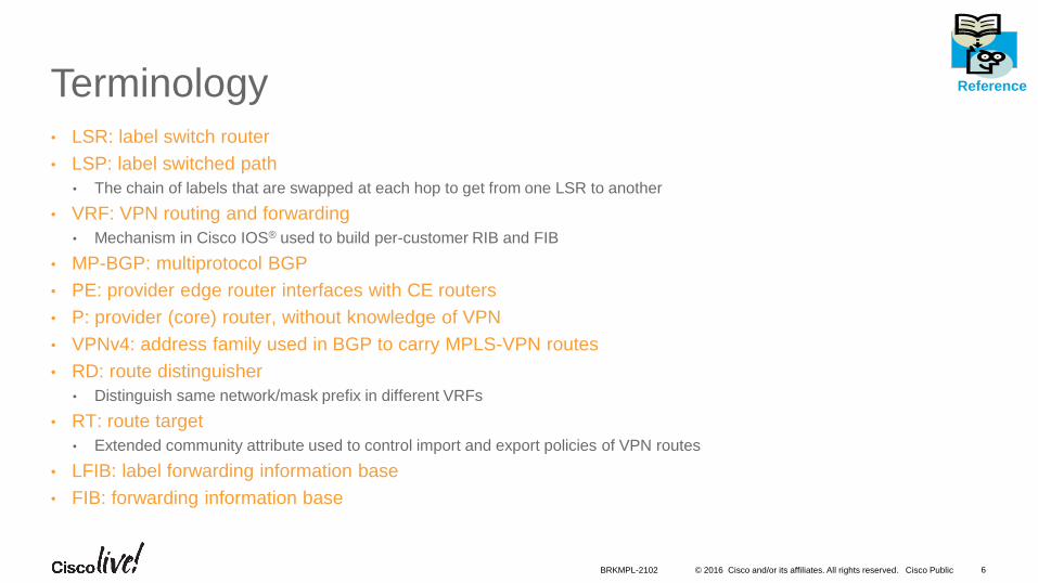
Terminology• LSR: label switch router
• LSP: label switched path
• The chain of labels that are swapped at each hop to get from one LSR to another
• VRF: VPN routing and forwarding
• Mechanism in Cisco IOS® used to build per-customer RIB and FIB
• MP-BGP: multiprotocol BGP
• PE: provider edge router interfaces with CE routers
• P: provider (core) router, without knowledge of VPN
• VPNv4: address family used in BGP to carry MPLS-VPN routes
• RD: route distinguisher
• Distinguish same network/mask prefix in different VRFs
• RT: route target
• Extended community attribute used to control import and export policies of VPN routes
• LFIB: label forwarding information base
• FIB: forwarding information base
Reference
BRKMPL-2102 6

• IP/VPN Overview
• IP/VPN Deployment Scenarios
• Best Practices
• Use-Cases
• Conclusion
Agenda

• IP/VPN Overview
• Technology Overview (How It Works)
• Configuration Overview
• IP/VPN Deployment Scenarios
• Best Practices
• Use-Cases
• Conclusion
Agenda

© 2016 Cisco and/or its affiliates. All rights reserved. Cisco Public
IP/VPN Technology Overview
• More than one routing and forwarding tables
• Control plane—VPN route propagation
• Data or forwarding plane—VPN packet forwarding
BRKMPL-2102 9

© 2016 Cisco and/or its affiliates. All rights reserved. Cisco Public
IP/VPN Technology
• MPLS based IP/VPN Topology / Connection Model
PE
MPLS Network
MP-iBGP Session
PE
P P
P P
CE CE
CECE
P Routers
Sit inside the network
Forward packets by looking at labels
Share a common IGP with PE
PE Routers
Sit at the Edge of MPLS Network
Use MPLS with P routers
Use IP with CE routers
Distributes VPN routes using MP-BGP sessions to other PE routers
CE Routers
Sit at the Edge
Use IP with PE routers (and C routers)
Exchange IP routes with PE routers using IP routing protocol
BRKMPL-2102 10

© 2016 Cisco and/or its affiliates. All rights reserved. Cisco Public
IP/VPN Technology OverviewSeparate Routing Tables at PE
CE2
Customer Specific Routing Table
• Routing (RIB) and forwarding table (CEF) dedicated to VPN customer
• VPN1 routing table• VPN2 routing table
• Referred to as VRF table for <named VPN>
IOS: “show ip route vrf <name>”
IOS-XR:“sh route vrf <name> ipv4
NX-OS: “sh ip route vrf <name>”
Global Routing Table
• Created when IP routing is enabled on PE.
• Populated by OSPF, ISIS, etc. running inside the MPLS network
IOS: “show ip route”
IOS-XR:“sh route ipv4 unicast”
NX-OS: “sh ip route”
PE
CE1
VPN 1
VPN 2
MPLS Network IGP (OSPF, ISIS)
BRKMPL-2102 11

© 2016 Cisco and/or its affiliates. All rights reserved. Cisco Public
IP/VPN Technology OverviewVirtual Routing and Forwarding (VRF) Instance
• VRF = Representation of VPN customer inside the MPLS network • Each customer VPN is associated with at least one VRF
• VRF configured on each PE and associated with PE-CE interface(s)• Privatize an interface, i.e., coloring of the interface
• No changes needed at CE IOS_PE(conf)#interface Ser0/0
IOS_PE(conf)#ip vrf forwarding blue
IOS_PE(conf)#ip vrf blue
CE2
PE
CE1
VPN 1
VPN 2
MPLS Network IGP (OSPF, ISIS)
VRF Blue
VRF
Green
Ser0/0
BRKMPL-2102 12

© 2016 Cisco and/or its affiliates. All rights reserved. Cisco Public
IP/VPN Technology OverviewVirtual Routing and Forwarding Instance
• PE installs the VPN customer routes in VRF routing table(s)
• VPN routes are learned from CE routers or remote PE routers
• VRF-aware routing protocol (static, RIP, BGP, EIGRP, OSPF) on each PE
• PE installs the internal routes (IGP) in global routing table
• VPN customers can use overlapping IP addresses
• BGP plays a key role. Let’s understand few BGP specific details..…
CE2
PE
CE1
VPN 1
VPN 2
MPLS Network IGP (OSPF, ISIS)
VRF Blue
VRF Green
EIGRP, eBGP, OSPF, RIPv2, Static Routing Advertisements
BRKMPL-2102 13

© 2016 Cisco and/or its affiliates. All rights reserved. Cisco Public
IP/VPN Technology OverviewVPN Control Plane
• PE routers exchange VPN routes with other PE routers using BGP
• Multi-Protocol BGP aka MP-BGP
• PE routers advertise the routes to their CE routers
PE
MPLS Networ
PE
PE
MP-iBGP Session
BRKMPL-2102 14

© 2016 Cisco and/or its affiliates. All rights reserved. Cisco Public
IP/VPN Technology OverviewVPN Control Plane = Multi-Protocol BGP (MP-BGP)
MP-BGP on PE Customizes the VPN Customer Routing Information as per the Locally Configured VRF Information using:
• Route Distinguisher (RD)
• Route Target (RT)
• Label
8 Bytes
Route-Target
3 Bytes
Label
1:1
8 Bytes 4 Bytes
RD IPv4
VPNv4
10.1.1.0
MP-BGP UPDATE Message
Showing VPNv4 route, RT,
Label only
BRKMPL-2102 15
© 2016 Cisco and/or its affiliates. All rights reserved. Cisco Public
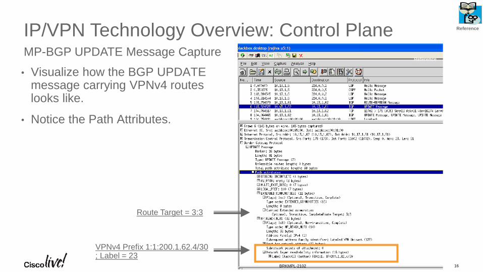
IP/VPN Technology Overview: Control Plane
• Visualize how the BGP UPDATE message carrying VPNv4 routes looks like.
• Notice the Path Attributes.
MP-BGP UPDATE Message Capture
VPNv4 Prefix 1:1:200.1.62.4/30 ; Label = 23
Route Target = 3:3
Reference
Reference
BRKMPL-2102 16

© 2016 Cisco and/or its affiliates. All rights reserved. Cisco Public
IP/VPN Technology Overview: Control PlaneRoute-Distinguisher (rd)
• VPN customer IPv4 prefix is converted into a VPNv4 prefix by appending the RD (1:1, say) to the IPv4 address (200.1.64.0, say) => 1:1:200.1.64.0
• Makes the customer’s IPv4 address unique inside the SP MPLS network.
• Route Distinguisher (rd) is configured in the VRF at PE
• RD is not a BGP attribute, just a field.
IOS_PE#
!
ip vrf green
rd 1:1
!
* After 12.4(3)T, 12.4(3) 12.2(32)S, 12.0(32)S etc., RD Configuration within VRF Has Become Optional. Prior to That, It Was Mandatory.
8 Bytes
Route-Target
3 Bytes
Label
1:1
8 Bytes 4 Bytes
RD IPv4
VPNv4
200.1.64.0
MP-BGP UPDATE Message
Showing VPNv4 route, RT,
Label only
BRKMPL-2102 17

© 2016 Cisco and/or its affiliates. All rights reserved. Cisco Public
IP/VPN Technology Overview: Control PlaneRoute-Target (rt)
• Route-target (rt) identifies which VRF(s) keep which VPN prefixes
• rt is an 8-byte extended community attribute.
• Each VRF is configured with a set of route-targets at PE
• Export and Import route-targets must be the same for any-to-any IP/VPN
• Export route-target values are attached to VPN routes in PE->PE MP-iBGPadvertisements
8 Bytes
Route-Target
3 Bytes
Label
1:1
8 Bytes 4 Bytes
RD IPv4
VPNv4
10.1.1.0 1:2
IOS_PE#
!
ip vrf green
route-target import 3:3
route-target export 3:3
route-target export 10:3
!
BRKMPL-2102 18

© 2016 Cisco and/or its affiliates. All rights reserved. Cisco Public
IP/VPN Technology Overview: Control PlaneLabel
• PE assigns a label for the VPNv4 prefix;
• Next-hop-self towards MP-iBGP neighbors by default i.e. PE sets the NEXT-HOP attribute to its own address (loopback)
• Label is not an attribute.
• PE addresses used as BGP next-hop must be uniquely known in IGP
• Do not summarize the PE loopback addresses in the core
3 Bytes
Label
1:1
8 Bytes 4 Bytes
RD IPv4
VPNv4
10.1.1.0 2:2 50
8 Bytes
Route-Target
BRKMPL-2102 19

© 2016 Cisco and/or its affiliates. All rights reserved. Cisco Public
IP/VPN Technology Overview: Control PlanePutting it all together
1. PE1 receives an IPv4 update (eBGP/OSPF/ISIS/RIP/EIGRP)
2. PE1 translates it into VPNv4 address and constructs the MP-iBGP UPDATE message
• Associates the RT values (export RT =1:2, say) per VRF configuration
• Rewrites next-hop attribute to itself
• Assigns a label (100, say); Installs it in the MPLS forwarding table.
3. PE1 sends MP-iBGP update to other PE routers
10.1.1.0/24
Next-Hop=CE-1
MP-iBGP Update:RD:10.1.1.0
Next-Hop=PE-1RT=1:2, Label=100
1
3
10.1.1.0/24
PE1 PE2
P
P P
PCE2
MPLS Backbone
Site 1 Site 2
CE1
2
1
2
3
BRKMPL-2102 20

© 2016 Cisco and/or its affiliates. All rights reserved. Cisco Public
IP/VPN Technology Overview: Control PlanePutting it all together
4. PE2 receives and checks whether the RT=1:2 is locally configured as ‘import RT’ within any VRF, if yes, then
• PE2 translates VPNv4 prefix back to IPv4 prefix
• Updates the VRF CEF Table for 10.1.1.0/24 with label=100
5. PE2 advertises this IPv4 prefix to CE2 (using whatever routing protocol)
10.1.1.0/24
Next-Hop=CE-1
MP-iBGP Update:RD:10.1.1.0
Next-Hop=PE-1RT=1:2, Label=100
1
3
10.1.1.0/24
PE1 PE2
P
P P
PCE2
MPLS Backbone
Site 1 Site 2
CE1
2
5
10.1.1.0/24
Next-Hop=PE-2
4
4
5
BRKMPL-2102 21

© 2016 Cisco and/or its affiliates. All rights reserved. Cisco Public
IP/VPN Technology OverviewForwarding Plane
10.1.1.0/24
PE1 PE2
P
P P
PCE2
MPLS Backbone
Site 1 Site 2
CE1
Customer/VPN Forwarding Table
• Stores VPN routes with associated labels• VPN routes learned via BGP• Labels learned via BGP
IOS: show ip cef vrf <name>
NX-OS: show forwarding vrf <name>
IOS-XR: show cef vrf <name> ipv4
Global Forwarding Table
• Stores next-hop i.e. PE routes with associated labels
• Next-hop i.e. PE routes learned through IGP• Label learned through LDP or RSVP
IOS:show ip cef
NX-OS: show forwarding ipv4
IOS-XR: show cef ipv4
BRKMPL-2102 22

© 2016 Cisco and/or its affiliates. All rights reserved. Cisco Public
IP/VPN Technology Overview: Forwarding PlanePacket Forwarding
• PE2 imposes two labels (MPLS headers) for each IP packet going to site2
• Outer label is learned via LDP; Corresponds to PE1 address (e.g. IGP route)
• Inner label is learned via BGP; corresponds to the VPN address (BGP route)
• P1 does the Penultimate Hop Popping (PHP)
• PE1 retrieves IP packet (from received MPLS packet) and forwards it to CE1.
10.1.1.0/24
PE1 PE2
CE2CE1
Site 1 Site 2
10.1.1.1
10.1.1.110050
10.1.1.1
10.1.1.1100
10.1.1.1 10025
IP Packet
MPLS Packet
IP Packet
P4
P1 P2
P3
BRKMPL-2102 23

© 2016 Cisco and/or its affiliates. All rights reserved. Cisco Public
IP/VPN Technology Overview: Forwarding PlaneMPLS IP/VPN Packet Capture
• Visualize an MPLS VPN Packet on the wire.
Inner MPLS Header
Outer MPLS header
IP Header
Ethernet Header
Reference
Reference
BRKMPL-2102 24

• IP/VPN Overview
• Technology Overview (How It Works)
• Configuration Overview (IOS, IOS-XR and NX-OS)
• IP/VPN Deployment Scenarios
• Best Practices
• Use-Cases
• Conclusion
Agenda

© 2016 Cisco and/or its affiliates. All rights reserved. Cisco Public
MPLS based IP/VPN Sample Configuration (IOS)
PE-P Configuration
ip vrf VPN-A
rd 1:1
route-target export 100:1
route-target import 100:1
interface Serial0
ip address 192.168.10.1/24
ip vrf forwarding VPN-A
VRF Definition
PE
1
10.1.1.0/24
PE1
CE1Site 1
192.168.10.1Se0
Interface Serial1
ip address 130.130.1.1 255.255.255.252
mpls ip
router ospf 1
network 130.130.1.0 0.0.0.3 area 0
PE
1Se0
P
PE1s1
Reference
Reference
vrf definition VPN-A
rd 1:1
address-family ipv4
route-target export 100:1
route-target import 100:1
interface Serial0
ip address 192.168.10.1/24
vrf forwarding VPN-A
BRKMPL-2102 26

© 2016 Cisco and/or its affiliates. All rights reserved. Cisco Public
MPLS based IP/VPN Sample Configuration (IOS)PE: MP-IBGP Config
RR: MP-IBGP Config
router bgp 1
neighbor 1.2.3.4 remote-as 1
neighbor 1.2.3.4 update-source loopback0
!
address-family vpnv4
neighbor 1.2.3.4 activate
neighbor 1.2.3.4 send-community both
!
PE
1
router bgp 1
no bgp default route-target filter
neighbor 1.2.3.6 remote-as 1
neighbor 1.2.3.6 update-source loopback0
!
address-family vpnv4
neighbor 1.2.3.6 route-reflector- client
neighbor 1.2.3.6 activate
!
RR
PE1 PE2
R
R
PE1 PE2
R
R
Reference
BRKMPL-2102 27

© 2016 Cisco and/or its affiliates. All rights reserved. Cisco Public
MPLS based IP/VPN Sample Configuration (IOS)
router bgp 1
!
address-family ipv4 vrf VPN-A
neighbor 192.168.10.2 remote-as 2
neighbor 192.168.10.2 activate
exit-address-family
!
PE-CE Routing: BGP
PE-CE Routing: OSPF
router ospf 1
!
router ospf 2 vrf VPN-A
network 192.168.10.0 0.0.0.255 area 0
redistribute bgp 1 subnets
!
PE1
PE1
10.1.1.0/24
PE1
CE1Site 1
192.168.10.1
192.168.10.2
10.1.1.0/24
PE1
Site 1
192.168.10.1
192.168.10.2
CE1
Reference
BRKMPL-2102 28

© 2016 Cisco and/or its affiliates. All rights reserved. Cisco Public
MPLS based IP/VPN Sample Configuration (IOS)
router rip
!
address-family ipv4 vrf VPN-A
version 2
no auto-summary
network 192.168.10.0
redistribute bgp 1 metric transparent
!
PE-CE Routing: RIP
PE-CE Routing: EIGRProuter eigrp 1
!
address-family ipv4 vrf VPN-A
no auto-summary
network 192.168.10.0 0.0.0.255
autonomous-system 10
redistribute bgp 1 metric 100000 100
255 1 1500
!
10.1.1.0/24
PE1
CE1Site 1
192.168.10.1
192.168.10.2
10.1.1.0/24
PE1
Site 1
192.168.10.1
192.168.10.2
CE1
PE1
PE1
Reference
BRKMPL-2102 29

© 2016 Cisco and/or its affiliates. All rights reserved. Cisco Public
MPLS based IP/VPN Sample Configuration (IOS)
ip route vrf VPN-A 10.1.1.0 255.255.255.0
192.168.10.2
PE-CE Routing: Static
PE-CE: MB-iBGP Routes to VPN
router rip
address-family ipv4 vrf VPN-A
version 2
redistribute bgp 1 metric transparent
no auto-summary
network 192.168.10.0
exit-address-family
If PE-CE Protocol Is Non-BGP (Such as RIP), then Redistribution of
VPN Routes from MP-IBGP Is Required (Shown Below for RIP) -
10.1.1.0/24
PE1
CE1Site 1
192.168.10.1
192.168.10.2
PE1
R
R
CE1
Site 1
PE1
PE1
Reference
BRKMPL-2102 30

© 2016 Cisco and/or its affiliates. All rights reserved. Cisco Public
MPLS based IP/VPN Sample Configuration (IOS)
• For hands-on learning, please attend the lab sessions:
• LTRMPL-2104 Implementing MPLS in SP Networks (Intro Level)
• LTRMPL-2105 Implementing MPLS in SP Networks (Advanced Level)
• Having familiarized with IOS based config, let’s peek through IOS-XR and NX-OS config for VPNs
router bgp 1
neighbor 1.2.3.4 remote-as 1
neighbor 1.2.3.4 update-source loopback 0
address-family ipv4 vrf VPN-A
redistribute {rip|connected|static|eigrp|ospf}
PE-RR (VPN Routes to VPNv4)
If PE-CE Protocol Is Non-BGP, then Redistribution of Local
VPN Routes into MP-IBGP Is Required (Shown Below)
PE1
R
R
CE1
Site 1
PE1
Reference
BRKMPL-2102 31

© 2016 Cisco and/or its affiliates. All rights reserved. Cisco Public
MPLS based IP/VPN Sample Config (IOS-XR)
PE-P Configuration
vrf VPN-A
address-family ipv4 unicast
import route-target 100:1
export route-target 100:1
!
router bgp 1
vrf VPN-A
rd 1:1
Interface GE0
ipv4 address 192.168.10.1 255.255.255.0
vrf VPN-A
VRF Definition
PE
1
10.1.1.0/24
PE1
CE1Site 1
192.168.10.1
GE
0
mpls ip
int GE1
!
router ospf 1
area 0
interface GE1
PE
1GE
0
P
PE1GE1
Reference
Reference
BRKMPL-2102 32

© 2016 Cisco and/or its affiliates. All rights reserved. Cisco Public
MPLS based IP/VPN Sample Config (IOS-XR)PE: MP-IBGP Config
RR: MP-IBGP Config
router bgp 1
router-id 1.2.3.1
address-family vpnv4 unicast
!
neighbor 1.2.3.4
remote-as 1
update-source loopback0
address-family vpnv4 unicast
send-community extended
!
PE
1
router bgp 1
router-id 1.2.3.4
address-family vpnv4 unicast
!
neighbor 1.2.3.1
remote-as 1
update-source loopback0
address-family vpnv4 unicast
send-community extended
route-reflector-client
!
RR
PE1 PE2
R
R
PE1 PE2
R
R
Reference
BRKMPL-2102 33

© 2016 Cisco and/or its affiliates. All rights reserved. Cisco Public
MPLS based IP/VPN Sample Config (IOS-XR)router bgp 1
!
vrf VPN-A
neighbor 192.168.10.2
remote-as 2
address-family ipv4 unicast
route-policy pass-all in|out
!
!
!
!
PE-CE Routing: BGP
PE-CE Routing: OSPF
router ospf 2
vrf VPN-A
address-family ipv4 unicast
redistribute bgp 1
!
area 0
interface GE0
!
PE1
PE1
10.1.1.0/24
PE1
CE1Site 1
192.168.10.1
192.168.10.2
10.1.1.0/24
PE1
Site 1
192.168.10.1
192.168.10.2
CE1
Reference
GE0
GE0
BRKMPL-2102 34

© 2016 Cisco and/or its affiliates. All rights reserved. Cisco Public
MPLS based IP/VPN Sample Config (IOS-XR)
router rip
vrf VPN-A
interface GE0
redistribute bgp 1
!
PE-CE Routing: RIP
PE-CE Routing: EIGRP
router eigrp 1
vrf VPN-A
address-family ipv4
as 10
default-metric 100000 100 255 1 1500
interface GE0
redistribute bgp 1
10.1.1.0/24
PE1
CE1Site 1
192.168.10.1
192.168.10.2
10.1.1.0/24
PE1
Site 1
192.168.10.1
192.168.10.2
CE1
PE1
PE1
Reference
GE0
GE0
BRKMPL-2102 35

© 2016 Cisco and/or its affiliates. All rights reserved. Cisco Public
MPLS based IP/VPN Sample Config (IOS-XR)
router static
vrf VPN-A
address-family ipv4 unicast
ip route 10.1.1.0/8 192.168.10.2
PE-CE Routing: Static
10.1.1.0/24
PE1
CE1Site 1
192.168.10.1
192.168.10.2
PE1
Reference
GE0
BRKMPL-2102 36

© 2016 Cisco and/or its affiliates. All rights reserved. Cisco Public
MPLS based IP/VPN Sample Config (IOS-XR)
router bgp 1
vrf VPN-A
address-family ipv4 unicast
redistribute {rip|connected|static|eigrp|ospf}
PE-RR (VPN Routes to VPNv4)
If PE-CE Protocol Is Non-BGP, then Redistribution of Local VPN Routes into MP-IBGP Is
Required (Shown Below)
PE1
R
R
CE1
Site 1
PE1
Reference
BRKMPL-2102 37

© 2016 Cisco and/or its affiliates. All rights reserved. Cisco Public
MPLS based IP/VPN Sample Config (NX-OS)
PE-P Configuration
vrf context VPN-A
rd 1:1
address-family ipv4 unicast
route-target import 1:1
route-target export 1:1
Interface GE0
ip address 192.168.10.1 255.255.255.0
vrf member VPN-A
VRF Definition
PE
1
10.1.1.0/24
PE1
CE1Site 1
192.168.10.1
GE
0
Interface GE1
ip address 130.130.1.1 255.255.255.252
mpls ip
ip ospf 1 area 0
router ospf 1
PE
1GE
0
P
PE1GE1
Reference
Reference
BRKMPL-2102 38

© 2016 Cisco and/or its affiliates. All rights reserved. Cisco Public
MPLS based IP/VPN Sample Config (NX-OS)PE: MP-IBGP Config
RR: MP-IBGP Config
router bgp 1
router-id 1.2.3.1
neighbor 1.2.3.4 remote-as 1
update-source loopback0
address-family vpnv4 unicast
send-community extended
!
PE
1
router bgp 1
router-id 1.2.3.4
neighbor 1.2.3.1 remote-as 1
update-source loopback0
address-family vpnv4 unicast
send-community extended
route-reflector-client
!
RR
PE1 PE2
R
R
PE1 PE2
R
R
Reference
BRKMPL-2102 39

© 2016 Cisco and/or its affiliates. All rights reserved. Cisco Public
MPLS based IP/VPN Sample Config (NX-OS)
router bgp 1
!
vrf VPN-A
neighbor 192.168.10.2 remote-as 2
address-family ipv4 unicast
!
PE-CE Routing: BGP
PE-CE Routing: OSPFrouter ospf 2
vrf VPN-A
address-family ipv4 unicast
redistribute bgp 1 route-map name
!
interface GE1
ip address 192.168.10.1/24
ip router ospf 2 area 0
PE1
PE1
10.1.1.0/24
PE1
CE1Site 1
192.168.10.1
192.168.10.2
10.1.1.0/24
PE1
Site 1
192.168.10.1
192.168.10.2
CE1
Reference
GE0
GE0
BRKMPL-2102 40

© 2016 Cisco and/or its affiliates. All rights reserved. Cisco Public
MPLS based IP/VPN Sample Config (NX-OS)
router rip ripxyz1
vrf VPN-A
address-family ipv4 unicast
redistribute bgp 1 route-map name
!
interface GE0
vrf member vpn1
ip router rip ripxyz1
PE-CE Routing: RIP
PE-CE Routing: EIGRProuter eigrp 100
vrf VPN-A
address-family ipv4
redistribute bgp 1 route-map name
!
interface GE0
vrf member vpn1
ip router eigrp 100
site-of-origin 1:11
10.1.1.0/24
PE1
CE1Site 1
192.168.10.1
192.168.10.2
10.1.1.0/24
PE1
Site 1
192.168.10.1
192.168.10.2
CE1
PE1
PE1
Reference
GE0
GE0
BRKMPL-2102 41

© 2016 Cisco and/or its affiliates. All rights reserved. Cisco Public
MPLS based IP/VPN Sample Config (NX-OS)
vrf context VPN-A
ip route 10.1.1.0/8 192.168.10.2
PE-CE Routing: Static
10.1.1.0/24
PE1
CE1Site 1
192.168.10.1
192.168.10.2
PE1
Reference
GE0
BRKMPL-2102 42

© 2016 Cisco and/or its affiliates. All rights reserved. Cisco Public
MPLS based IP/VPN Sample Config (NX-OS)
router bgp 1
vrf VPN-A
address-family ipv4 unicast
redistribute {rip|direct|static|eigrp|ospf} route-map name
PE-RR (VPN Routes to VPNv4)
If PE-CE Protocol Is Non-BGP, then Redistribution of Local
VPN Routes into MP-IBGP Is Required (Shown Below)
PE1
R
R
CE1
Site 1
PE1
Reference
BRKMPL-2102 43
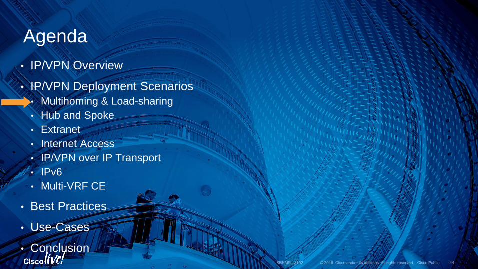
• IP/VPN Overview
• IP/VPN Deployment Scenarios
• Multihoming & Load-sharing
• Hub and Spoke
• Extranet
• Internet Access
• IP/VPN over IP Transport
• IPv6
• Multi-VRF CE
• Best Practices
• Use-Cases
• Conclusion
Agenda

© 2016 Cisco and/or its affiliates. All rights reserved. Cisco Public
PE11
PE2
MPLS Backbone
PE12
CE1
Site A
171.68.2.0/24
Site B
CE2
RR
IP/VPN Deployment Scenarios:1. Multi-homing & Loadsharing of VPN Traffic
• VPN sites (such as Site A) could be multihomed
• VPN sites need the traffic to (the site A) be loadshared
Route Advertisement
BRKMPL-2102 45

© 2016 Cisco and/or its affiliates. All rights reserved. Cisco Public
PE11
PE2
MPLS Backbone
PE12
CE1
Site A
171.68.2.0/24
Site B
CE2
RR
IP/VPN Deployment Scenarios:1. Multi-homing & Loadsharing of VPN Traffic
• Configure unique RD per VRF per PE for multihomed site/interfaces
• Assuming RR exists
• Enable eiBGP multipath within the relevant BGP VRF address-family at remote PE routers such as PE2 (why PE2?).
rd 300:11
route-target both 1:1
1
rd 300:12
route-target both 1:1
1
rd 300:13
route-target both 1:1
<BGP>
address-family ipv4 vrf green
maximum-paths eibgp 2
2
BRKMPL-2102 46

© 2016 Cisco and/or its affiliates. All rights reserved. Cisco Public
IP/VPN Deployment Scenarios:
• What if PE11-CE link fails?
• Wait for BGP convergence (~seconds)
1. VPN Fast Convergence—PE-CE Link Failure
PE11
PE2
MPLS Backbone
PE12
171.68.2.0/24
RR VPN Traffic
Redirected VPN Traffic
Traffic Is Dropped by PE11
CE1 CE2
Site A Site B
Supported in IOS,
and IOS-XR
BRKMPL-2102 47

© 2016 Cisco and/or its affiliates. All rights reserved. Cisco Public
IP/VPN Deployment Scenarios:1. VPN Fast Convergence—PE-CE Link Failure – PIC Edge Feature
• BGP PIC Edge feature provides fast convergence (~msec) .
• PE11 temporarily redirects the CE1 bound traffic to PE12 until BGP has converged
• BGP PIC Edge is independent of whether multipath is enabled on PE2 or not
PE2
MPLS Backbone
PE12
171.68.2.0/24
Traffic Is Redirected by PE11
VPN Traffic
Redirected VPN Traffic
Site A Site B
CE2CE1
PE11
RR
Supported in IOS,
and IOS-XR 3.4
BRKMPL-2102 48

• IP/VPN Overview
• IP/VPN Deployment Scenarios
• Multihoming & Load-sharing
• Hub and Spoke
• Extranet
• Internet Access
• IP/VPN over IP Transport
• IPv6
• Multi-VRF CE
• Best Practices
• Use-Cases
• Conclusion
Agenda

© 2016 Cisco and/or its affiliates. All rights reserved. Cisco Public
IP/VPN Deployment Scenarios:
• Many VPN deployments require hub and spoke topology
• Spoke to spoke communication via Hub site only
• Example: ATM Machines to HQ, Router Management traffic to NMS/DC
• Despite MPLS based IP/VPN’s implicit any-to-any, i.e. full-mesh connectivity, hub and spoke service can easily be offered
• Uses different import and export of route-target (RT) values
• Requires unique RD per VRF per PE
• Independent PE-CE routing protocol per site
2. Hub and Spoke Service
BRKMPL-2102 50

© 2016 Cisco and/or its affiliates. All rights reserved. Cisco Public
IP/VPN Deployment Scenarios:
• Two configuration Options :
1. 1 PE-CE interface to Hub & 1 VRF;
2. 2 PE-CE interfaces to Hub & 2 VRFs;
• Use option#1 if VPN Hub site advertises default or summary routes towards the Spoke sites, otherwise use Option#2
2. Hub and Spoke Service
* HDVRF Feature Is Discussed Later
BRKMPL-2102 51

© 2016 Cisco and/or its affiliates. All rights reserved. Cisco Public
IP/VPN Deployment Scenarios: 2. Hub and Spoke Service: IOS Configuration – Option#1
PE-SA
PE-Hub
MPLS VPN Backbone
PE-SB
CE-SA
CE-SBSpoke B
Spoke A
171.68.1.0/24
171.68.2.0/24
Eth0/0
<VRF GREEN for Spoke A>
rd 300:111
route-target export 1:1
route-target import 2:2
<VRF GREEN for SPOKE B>
rd 300:112
route-target export 1:1
route-target import 2:2
<VRF GREEN for HUB>
rd 300:11
route-target export 2:2
route-target import 1:1
Note: Only RD and RT Configuration Shown Here
CE-Hub
Import and Export RT Values Must Be Different
Supported in IOS,
NXOS and IOS-XR
BRKMPL-2102 52

© 2016 Cisco and/or its affiliates. All rights reserved. Cisco Public
IP/VPN Deployment Scenarios: 2. Hub and Spoke Service: IOS Configuration – Option#2
PE-SA
PE-Hub
MPLS VPN Backbone
PE-SB
CE-SA
CE-SBSpoke B
Spoke A
171.68.1.0/24
171.68.2.0/24
Eth0/0.2
Eth0/0.1
<VRF GREEN for Spoke A>
rd 300:111
route-target export 1:1
route-target import 2:2
<VRF GREEN for Spoke B>
rd 300:112
route-target export 1:1
route-target import 2:2
<VRF IN for Hub>
rd 300:12
route-target export 2:2
<VRF IN for Hub>
rd 300:11
route-target import 1:1
CE-Hub
Import and Export RT Values Must Be Different
Note: Only RD and RT Configuration Shown Here
Supported in IOS,
NXOS and IOS-XR
BRKMPL-2102 53

© 2016 Cisco and/or its affiliates. All rights reserved. Cisco Public
IP/VPN Deployment Scenarios:
• If BGP is used between every PE and CE, then allowas-in and as-override* knobs must be used at the PE_Hub**
• Otherwise AS_PATH looping will occur
2. Hub and Spoke Service: Configuration – Option#2
* Only If Hub and Spoke Sites Use the Same BGP ASN
** Configuration for This Is Shown on the Next Slide
Supported in IOS,
NXOS and IOS-XR
BRKMPL-2102 54

© 2016 Cisco and/or its affiliates. All rights reserved. Cisco Public
<BGP>
address-family ipv4 vrf HUB-OUT
neighbor <CE> allowas-in 2
IP/VPN Deployment Scenarios: 2. Hub and Spoke Service: Configuration – Option#2
PE-SA
PE-Hub
MPLS VPN BackbonePE-SB
CE-SA
CE-SBSpoke B
Spoke A
171.68.1.0/24
171.68.2.0/24
Eth0/0.
2
Eth0/0.
1
<BGP>
address-family ipv4 vrf HUB-IN
neighbor <CE> as-override
CE-Hub
Supported in IOS,
NXOS and IOS-XR
BRKMPL-2102 55

© 2016 Cisco and/or its affiliates. All rights reserved. Cisco Public
IP/VPN Deployment Scenarios:
• Two VRFs at the PE-Hub:
• VRF HUB-IN to learn every spoke routes from remote PEs
• VRF HUB-OUT to advertise spoke routes or summary 171.68.0.0/16 routes to remote PEs
2. Hub and Spoke Service: Control Plane (Option#2)
PE-SA
MPLS Backbone
PE-SB
CE-SA
CE-SB
Spoke B
Spoke A
VRF HUB-OUT
VRF HUB-IN
VRF HUB-IN FIB and LFIB
Destination NextHop Label
171.68.1.0/24 PE-SA 40
171.68.2.0/24 PE-SB 50
171.68.1.0/24
171.68.2.0/24
VRF HUB-OUT FIB
Destination NextHop
171.68.0.0/16 CE-H1
MP-iBGP Update
171.68.0.0/16
Label 35
Route-Target 2:2
FIB—IP Forwarding TableLFIB—MPLS Forwarding Table
MP-iBGP Update
171.68.2.0/24
Label 50
Route-Target 1:1
MP-iBGP Update
171.68.1.0/24
Label 40
Route-Target 1:1
PE-Hub
CE-Hub
VRF FIB and LFIB
Destination NextHop Label
171.68.0.0/16 PE-Hub 35
171.68.1.0/24 CE-SA
VRF FIB and LFIB
171.68.0.0/16 PE-Hub 35
171.68.2.0/24 CE-SB
Supported in IOS,
NXOS and IOS-XR
BRKMPL-2102 56

© 2016 Cisco and/or its affiliates. All rights reserved. Cisco Public
PE-SA
PE-Hub
MPLS Backbone
IP/VPN Deployment Scenarios: 2. Hub and Spoke Service: Forwarding Plane (Option#2)
PE-SB
CE-SA
CE-SB
Spoke B
Spoke A
VRF HUB-OUT
VRF HUB-IN
171.68.1.0/24
171.68.2.0/24
L1 35 171.68.1.1
L2 40 171.68.1.1
171.68.1.1
L1 Is the Label to Get to PE-Hub
L2 Is the Label to Get to PE-SA
This Is How the Spoke-to-Spoke Traffic Flows
171.68.1.1
171.68.1.1
171.68.1.1
CE-Hub
Supported in IOS,
NXOS and IOS-XR
BRKMPL-2102 57
© 2016 Cisco and/or its affiliates. All rights reserved. Cisco Public
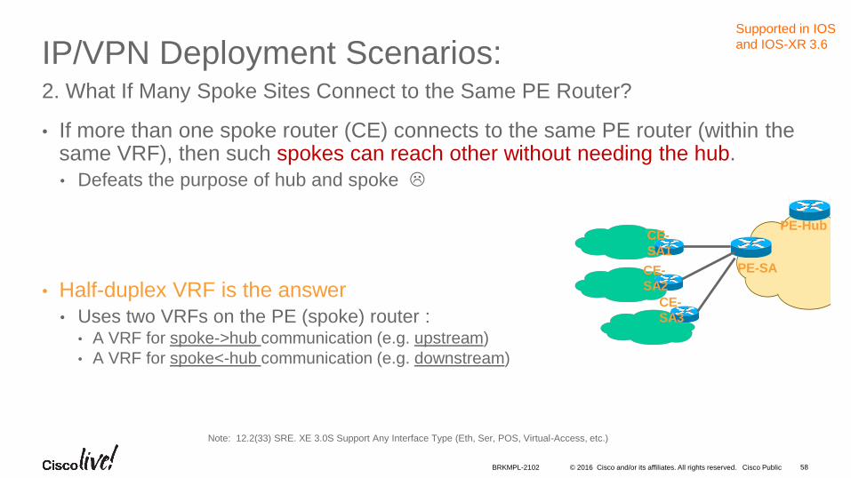
IP/VPN Deployment Scenarios:
• If more than one spoke router (CE) connects to the same PE router (within the same VRF), then such spokes can reach other without needing the hub.
• Defeats the purpose of hub and spoke
• Half-duplex VRF is the answer
• Uses two VRFs on the PE (spoke) router :• A VRF for spoke->hub communication (e.g. upstream)
• A VRF for spoke<-hub communication (e.g. downstream)
2. What If Many Spoke Sites Connect to the Same PE Router?
Note: 12.2(33) SRE. XE 3.0S Support Any Interface Type (Eth, Ser, POS, Virtual-Access, etc.)
PE-SA
CE-
SA1
CE-
SA2
CE-
SA3
PE-Hub
Supported in IOS
and IOS-XR 3.6
BRKMPL-2102 58

© 2016 Cisco and/or its affiliates. All rights reserved. Cisco Public
PE-SA
PE-Hub
MPLS Backbone
IP/VPN Deployment Scenarios: 2. Hub and Spoke Service: Half-Duplex VRF
CE-SA
CE-SB
Spoke B
Spoke A
171.68.1.0/24
171.68.2.0/24
1. PE-SA installs the Spoke routes only in downstream VRF i.e. green-down
2. PE-SA installs the Hub routes only in upstream VRF i.e. green-up
3. PE-SA forwards the incoming IP traffic (from Spokes) using upstream VRF i.e. green-up routing table.
4. PE-SA forwards the incoming MPLS traffic (from Hub) using downstream VRF i.e. green-down routing table
ip vrf HUB-OUT
description VRF for traffic to HUB
rd 300:12
route-target export 2:2
Interface GigEthernet 0/0 - 1
ip address 172.18.13.x 255.255.255.0
ip vrf forward green-up downstream green-down
..
Upstream VRF Downstream VRF
ip vrf green-up
description – For upstream traffic (to Hub)
rd 300:111
route-target import 2:2
ip vrf green-down
description - For downstream traffic (from Hub)
rd 300:112
route-target export 1:1
ip vrf HUB-IN
description VRF for traffic from HUB
rd 300:11
route-target import 1:1
CE-Hub
GE0/0
Hub Site
Supported in IOS
GE0/1
BRKMPL-2102 59

© 2016 Cisco and/or its affiliates. All rights reserved. Cisco Public
PE-SA
PE-Hub
MPLS Backbone
IP/VPN Deployment Scenarios: 2. Hub and Spoke Service: Half-Duplex VRF on every PE
• Single PE-CE interface on Hub
CE-SA
CE-SB
Spoke B
Spoke A
171.68.1.0/24
171.68.2.0/24
Interface GigEthernet 0/0 - 1
ip address 172.18.13.x 255.255.255.0
ip vrf forward green-up downstream green-down
..
Upstream VRF Downstream VRF
ip vrf green-up
description – For upstream traffic
rd 300:111
route-target import 2:2
ip vrf green-down
description – For downstream traffic
rd 300:112
route-target export 1:1
ip vrf HUB-IN
description VRF for traffic from HUB
rd 300:11
route-target import 1:1
CE-Hub
GE0/1Hub Site
Supported in IOS
Interface GigEthernet 1/1
ip address 172.1.1.1 255.255.255.0
ip vrf forward HUB-IN downstream HUB-OUT
..
ip vrf HUB-OUT
description VRF for traffic to HUB
rd 300:12
route-target export 2:2
GE0/0
BRKMPL-2102 60

• IP/VPN Overview
• IP/VPN Deployment Scenarios
• Multihoming & Load-sharing
• Hub and Spoke
• Extranet
• Internet Access
• IP/VPN over IP Transport
• IPv6
• Multi-VRF CE
• Best Practices
• Use-Cases
• Conclusion
Agenda

© 2016 Cisco and/or its affiliates. All rights reserved. Cisco Public
MPLS-VPN Deployment Scenarios
• MPLS based IP/VPN, by default, isolates one VPN customer from another
• Separate virtual routing table for each VPN customer
• Communication between VPNs may be required i.e. extranet
• External intercompany communication (dealers with manufacturer, retailer with wholesale provider, etc.)
• Management VPN, shared-service VPN, etc.
• Implemented by sharing import and export route-target (RT) values within the VRFs of extranets.
• Export-map or import-map may be used for advanced extranet.
3. Extranet VPN
BRKMPL-2102 62

© 2016 Cisco and/or its affiliates. All rights reserved. Cisco Public
VPN_B Site#1
180.1.0.0/16
MPLS-VPN Deployment Scenarios3. Extranet VPN – Simple Extranet (IOS Config sample)
71.8.0.0/16 PE1 PE2
MPLS BackboneVPN_A Site#2
P
VPN_A Site#1
<VRF for VPN_A>
route-target import 3000:111
route-target export 3000:111
route-target import 3000:222
<VRF for VPN_B>
route-target import 3000:222
route-target export 3000:222
route-target import 3000:111
192.6.0.0/16
All Sites of Both VPN_A and VPN_B Can Communicate
with Each Other
Supported in IOS,
NXOS and IOS-XR
BRKMPL-2102 63

© 2016 Cisco and/or its affiliates. All rights reserved. Cisco Public
180.1.0.0/16
VPN_B Site#1
MPLS-VPN Deployment Scenarios3. Extranet VPN – Advanced Extranet (IOS Config sample)
71.8.0.0/16 PE1 PE2
MPLS BackboneVPN_A Site#2
P
VPN_A Site#1
<VRF for VPN_A>
route-target import 3000:111
route-target export 3000:111
route-target import 3000:1
import map VPN_A_Import
export map VPN_A_Export
!
route-map VPN_A_Export permit 10
match ip address 1
set extcommunity rt 3000:2 additive
!
route-map VPN_A_Import permit 10
match ip address 2
!
access-list 1 permit 71.8.0.0 0.0.0.0
access-list 2 permit 180.1.0.0 0.0.0.0
<VRF for VPN_B>
route-target import 3000:222
route-target export 3000:222
route-target import 3000:2
import map VPN_B_Import
export map VPN_B_Export
!
route-map VPN_B_Export permit 10
match ip address 2
set extcommunity rt 3000:1 additive
!
route-map VPN_B_Import permit 10
match ip address 1
!
access-list 1 permit 71.8.0.0 0.0.0.0
access-list 2 permit 180.1.0.0 0.0.0.0
192.6.0.0/16
Only Site #1 of Both VPN_A and VPN_B Would Communicate
with Each Other
Lack of ‘Additive’
Would Result in
3000:222 Being
Replaced with 3000:1.
We Don’t Want That.
Supported in IOS,
NXOS and IOS-XR
BRKMPL-2102 64

• IP/VPN Overview
• IP/VPN Deployment Scenarios
• Multihoming & Load-sharing
• Hub and Spoke
• Extranet
• Internet Access
• IP/VPN over IP Transport
• IPv6
• Multi-VRF CE
• Best Practices
• Use-Cases
• Conclusion
Agenda

© 2016 Cisco and/or its affiliates. All rights reserved. Cisco Public
MPLS-VPN Deployment Scenarios
• Internet access service could be provided as another value-added service to VPN customers
• Security mechanism must be in place at both provider network and customer network
• To protect from the Internet vulnerabilities
• VPN customers benefit from the single point of contact for both Intranet and Internet connectivity
4. Internet Access Service to VPN Customers
BRKMPL-2102 66

© 2016 Cisco and/or its affiliates. All rights reserved. Cisco Public
MPLS-VPN Deployment Scenarios
Three Options to Provide the Internet Service -
1. VRF specific default route with “global” keyword
2. Separate PE-CE sub-interface (non-VRF)
3. Extranet with Internet-VRF
4. Internet Access: Design Options
BRKMPL-2102 67

© 2016 Cisco and/or its affiliates. All rights reserved. Cisco Public
MPLS-VPN Deployment Scenarios4. Internet Access: Design Options
VRF specific default route
• Static default route to move traffic from VRF to Internet (global routing table)
• Static routes for VPN customers to move traffic from Internet (global routing table) to VRF
• Works well, but doesn’t scale well (limited to default routing)
Extranet with Internet-VRF
• Internet routes inside a dedicated VRF (e.g. Internet-VRF)
• Extranet between Internet-VRF and Customer VRFs that need internet access
•
Separate PE-CE Interface
• Besides VRF interface, a global interface also connect to each VPN site
• May use eBGP on the global interface, if dynamic routing printernet routes are needed
• Works well and scales well, despite the operational overhead
BRKMPL-2102 68

© 2016 Cisco and/or its affiliates. All rights reserved. Cisco Public
192.168.1.2
A default route, pointing to the ASBR, is installed into the site VRF at each PE
The static route, pointing to the VRF interface, is installed in the global routing table and redistributed into BGP
PE1
ASBR
CE1MPLS Backbone
192.168.1.1
Internet GW
SO
P
PE1#
ip vrf VPN-A
rd 100:1
route-target both 100:1
Interface Serial0
ip address 192.168.10.1 255.255.255.0
ip vrf forwarding VPN-A
Router bgp 100
no bgp default ipv4-unicast
redistribute static
neighbor 192.168.1.1 remote 100
neighbor 192.168.1.1 activate
neighbor 192.168.1.1 next-hop-self
neighbor 192.168.1.1 update-source loopback0
ip route vrf VPN-A 0.0.0.0 0.0.0.0 192.168.1.1 global
ip route 71.8.0.0 255.255.0.0 Serial0
Site1
Internet71.8.0.0/16
IP/VPN Deployment Scenarios: Internet Access 4.1 Option#1: VRF Specific Default Route
Supported in IOS
BRKMPL-2102 69

© 2016 Cisco and/or its affiliates. All rights reserved. Cisco Public
Cons Using default route
for Internet
Routing does not allow any other default route for intra-VPN routing Increasing size of global routing table by leaking VPN routes
Static configuration (possibility of traffic blackholing)
IP/VPN Deployment Scenarios: Internet Access4.1 Option#1: VRF Specific Default Route (Forwarding)
71.8.0.0/16
PE1 PE2S0
P
PE1: VRF Routing/FIB Table
Destination Label/Interface
0.0.0.0/0 192.168.1.1 (Global)
Site-1 Serial 0
PE1: Global Routing/FIB Table
Destination Label/Interface
192.168.1.1/32 Label=30
71.8.0.0/16 Serial 0
Internet
(5.1.0.0/16)
PE2: Global Table and LFIB
Destination Label/Interface
192.168.1.2/32 Label=35
71.8.0.0/16 192.168.1.2
5.1.0.0/16 Serial 0
192.168.1.2
Pros
Different Internet gateways
Can be used for different VRFs
PE routers need not to hold the Internet table
Simple configuration
Site1
S
0
MPLS Backbone
192.168.1.1
5.1.1.130
MPLS Packet
5.1.1.1
IP Packet
71.8.1.135
5.1.1.1
IP Packet
71.8.1.1 IP Packet71.8.1.1
MPLS Packet
71.8.1.1
IP Packet
Supported in IOS,
BRKMPL-2102 70

© 2016 Cisco and/or its affiliates. All rights reserved. Cisco Public
PE1-CE1 has one sub-interface associated to a VRF for VPN routing
PE1-CE has another subinterface (global) for Internet routing
PE1 may have eBGP peering with CE1 over the global interface and advertise full Internet routes or a default route to CE1
PE2 must advertise VPN/site1 routes to the Internet.
ip vrf VPN-A
rd 100:1
route-target both 100:1
Interface Serial0.1
ip vrf forwarding VPN-A
ip address 192.168.20.1 255.255.255.0
frame-relay interface-dlci 100
!
Interface Serial0.2
ip address 71.8.10.1 255.255.0.0
frame-relay interface-dlci 200
!
Router bgp 100
no bgp default ipv4-unicast
neighbor 71.8.10.2 remote-as 502
71.8.0.0/16
CE1
MPLS Backbone
Internet GW
Se0.2
P
iBGP
Site1
Se0.1
InternetInternet
IP/VPN Deployment Scenarios: Internet Access 4.2 Option#2: Separate PE-CE Subinterfaces
192.168.1.2192.168.1.1
PE1 PE2
Supported in IOS,
NXOS and IOS-XR
BRKMPL-2102 71

© 2016 Cisco and/or its affiliates. All rights reserved. Cisco Public
CE Routing Table
VPN Routes Serial0.1
Internet Routes Serial0.2
PE1 Global Table and FIB
Internet Routes
192.168.1.1
192.168.1.1 Label=30
Pros
1. CE is dual-homed and can
perform Optimal Routing
2. Traffic Separation Done
by CE
Cons
1. PE to Hold Full Internet Routes
or default route via the Internet
GW
. BGP Complexities Introduced at
CE; CE1 May Need to Aggregate
to Avoid AS_PATH Looping
71.8.0.0/16
MPLS Backbone
PE-Internet GW
S0.2
P
Site1
S0.1
InternetInternet
IP/VPN Deployment Scenarios: Internet Access 4.2 Option#2: Separate PE-CE Subinterfaces (Forwarding)
192.168.1.2192.168.1.1
PE1 PE2
5.1.1.1
IP Packet
5.1.1.130
MPLS Packet 5.1.1.1
IP PacketCE1
Supported in IOS,
NXOS and IOS-XR
BRKMPL-2102 72

© 2016 Cisco and/or its affiliates. All rights reserved. Cisco Public
IP/VPN Deployment Scenarios: Internet Access
• The Internet routes could be placed within the VRF at the Internet-GW i.e., ASBR
• VRFs for customers could ‘extranet’ with the Internet VRF and receive either default, partial or full Internet routes
• Default route is recommended
• Be careful if multiple customer VRFs, at the same PE, are importing full Internet routes
• Works well only if the VPN customers don’t have overlapping addresses
4.3 Option#3: Extranet with Internet
Supported in IOS,
NXOS and IOS-XR
BRKMPL-2102 73
© 2016 Cisco and/or its affiliates. All rights reserved. Cisco Public
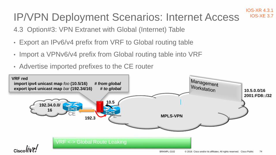
IP/VPN Deployment Scenarios: Internet Access
• Export an IPv6/v4 prefix from VRF to Global routing table
• Import a VPNv6/v4 prefix from Global routing table into VRF
• Advertise imported prefixes to the CE router
4.3 Option#3: VPN Extranet with Global (Internet) Table
192.34.0.0/
16
MPLS-VPN
10.5.0.0/16
2001:FD8::/32
VRF red
import ipv4 unicast map foo (10.5/16) # from global
export ipv4 unicast map bar (192.34/16) # to global
192.3
10.5
CE PE
IOS-XR 4.3.1
IOS-XE 3.7
VRF <-> Global Route Leaking
BRKMPL-2102 74

© 2016 Cisco and/or its affiliates. All rights reserved. Cisco Public
VRF <-> Global Route Leaking eBGP (CE) and iBGP (PE) Advertisement
• Export an IPv6/v4 prefix from VRF to Global routing table
• Import a VPNv6/v4 prefix from Global routing table into VRF
• Advertise imported prefixes to the CE router and optionally PE router
192.34.0.0/
16
MPLS-VPN
VRF red
import ipv4 unicast map foo (10.5/16) export # from global
export ipv4 unicast map bar (192.34/16) # to global
192.34
10.5
IOS-XR 4.3.1
IOS-XE 3.10
10.5.0.0/16
2001:FD8::/32
VRF <-> Global Route Leaking
CE PE
BRKMPL-2102 75

© 2016 Cisco and/or its affiliates. All rights reserved. Cisco Public
IP/VPN Deployment Scenarios: Internet Access
• If the VPN customers need Internet access without Internet routes, then VRF-aware NAT can be used at the Internet-GW i.e., ASBR
• The Internet GW doesn’t need to have Internet routes either
• Overlapping VPN addresses is no longer a problem
• More in the “VRF-aware NAT” slides…
4.4 Option#4: Using VRF-Aware NAT
Supported in IOS,
BRKMPL-2102 76

• IP/VPN Overview
• IP/VPN Deployment Scenarios
• Multihoming & Load-sharing
• Hub and Spoke
• Extranet
• Internet Access
• IP/VPN over IP Transport
• IPv6
• Multi-VRF CE
• Best Practices
• Use-Cases
• Conclusion
Agenda

© 2016 Cisco and/or its affiliates. All rights reserved. Cisco Public
IP/VPN Deployment Scenarios:
• MPLS/VPN (rfc2547) can also be deployed using IP transport
• No MPLS needed in the core
• PE-to-PE IP tunnel is used, instead of MPLS tunnel, for sending MPLS/VPN packets
• MPLS labels are still allocated for VPN prefixes by PE routers and used only by the PE routers
• MPLS/VPN packet is encapsulated inside an IP header
• IP tunnel could be point-to-point or Multipoint GRE encapsulation based.
5. Providing MPLS/VPN over IP TransportReference
http://www.cisco.com/en/US/docs/ios/interface/configuration/guide/ir_mplsvpnomgre.html
Supported in IOS,
NXOS and IOS-XR
BRKMPL-2102 78

© 2016 Cisco and/or its affiliates. All rights reserved. Cisco Public
IP/VPN Deployment Scenarios:5. Providing MPLS/VPN over IP Transport
Reference
Source -- http://www.cisco.com/en/US/docs/ios/interface/configuration/guide/ir_mplsvpnomgre.html
IP
CE1 CE2PE1 PE2
VRF
GRE/IP Tunnel
VRF
GRE/IP header and VPN label imposed on VPN traffic by PE1
VPN traffic is forwarded towards egress PE using IP forwarding
Egress PE2 decapsulates, and uses VPN label to forward packet to CE2
IP Header
GRE Header
VPN Label
Src AddDst Add
Data
Src AddDst Add
Data
Src AddDst Add
Data
IP Packet
Supported in IOS,
NXOS and IOS-XR
BRKMPL-2102 79

• IP/VPN Overview
• IP/VPN Deployment Scenarios
• Multihoming & Load-sharing
• Hub and Spoke
• Extranet
• Internet Access
• IP/VPN over IP Transport
• IPv6
• Multi-VRF CE
• Best Practices
• Use-Cases
• Conclusion
Agenda

© 2016 Cisco and/or its affiliates. All rights reserved. Cisco Public
IP/VPN Deployment Scenarios:6. IPv6 VPN Service
• Similar to IPv4 VPN, IPv6 VPN can also be offered.
• Referred to as “IPv6 VPN Provider Edge (6VPE)”.
• No modification on the MPLS core
• Core can stay on IPv4
• PE-CE interface can be single-stack IPv6 or dual-stack
• IPv4 and IPv6 VPNs can be offered on the same PE-CE interface
• Config and operation of IPv6 VPN are similar to IPv4 VPN
P
P
P
P
iBGP Sessions in VPNv4 and
VPNv6 Address-Families
VPN B
VPN A
v4 and v6VPN A
v6 Only
v4 and v6
VPN B
VPN A
v6 Only
v4 and v6
MPLS/VPN
Network
PE PE
PE PE
CE
CE
CE
CE
CE
Supported in IOS,
NXOS and IOS-XR
BRKMPL-2102 81
© 2016 Cisco and/or its affiliates. All rights reserved. Cisco Public
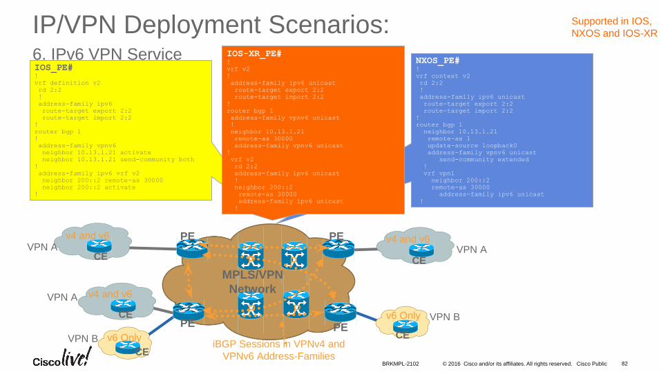
IP/VPN Deployment Scenarios:6. IPv6 VPN Service
P
P
P
P
iBGP Sessions in VPNv4 and
VPNv6 Address-Families
VPN B
VPN A
v4 and v6VPN A
v6 Only
v4 and v6
VPN B
VPN A
v6 Only
v4 and v6
MPLS/VPN
Network
PE PE
PE PE
CE
CE
CE
CE
CE
IOS_PE#!
vrf definition v2
rd 2:2
!
address-family ipv6
route-target export 2:2
route-target import 2:2
!
router bgp 1
!
address-family vpnv6
neighbor 10.13.1.21 activate
neighbor 10.13.1.21 send-community both
!
address-family ipv6 vrf v2
neighbor 200::2 remote-as 30000
neighbor 200::2 activate
!
NXOS_PE#!
vrf context v2
rd 2:2
!
address-family ipv6 unicast
route-target export 2:2
route-target import 2:2
!
router bgp 1
neighbor 10.13.1.21
remote-as 1
update-source loopback0
address-family vpnv6 unicast
send-community extended
!
vrf vpn1
neighbor 200::2
remote-as 30000
address-family ipv6 unicast
!
IOS-XR_PE#!
vrf v2
!
address-family ipv6 unicast
route-target export 2:2
route-target import 2:2
!
router bgp 1
address-family vpnv6 unicast
!
neighbor 10.13.1.21
remote-as 30000
address-family vpnv6 unicast
!
vrf v2
rd 2:2
address-family ipv6 unicast
!
neighbor 200::2
remote-as 30000
address-family ipv6 unicast
!
Supported in IOS,
NXOS and IOS-XR
BRKMPL-2102 82

• IP/VPN Overview
• IP/VPN Deployment Scenarios
• Multihoming & Load-sharing
• Hub and Spoke
• Extranet
• Internet Access
• IP/VPN over IP Transport
• IPv6
• Multi-VRF CE
• Best Practices
• Use-Cases
• Conclusion
Agenda

© 2016 Cisco and/or its affiliates. All rights reserved. Cisco Public
IP/VPN Deployment Scenarios:
• Is it possible for an IP router to keep multiple customer connections separated ?
• Yes, “multi-VRF CE” a.k.a. vrf-lite can be used
• “Multi-VRF CE” provides multiple virtual routing tables (and forwarding tables) per customer at the CE router
• Not a feature but an application based on VRF implementation
• Any routing protocol that is supported by normal VRF can be used in a multi-VRF CE implementation
• No MPLS functionality needed on CE, no label exchange between CE and any router (including PE)
• One deployment model is to extend the VRFs to the CE, another is to extend it further inside the Campus => Campus Virtualization
7. Providing Multi-VRF CE Service
Supported in IOS,
NXOS and IOS-XR
BRKMPL-2102 84

© 2016 Cisco and/or its affiliates. All rights reserved. Cisco Public
IP/VPN Deployment Scenarios:7. Multi-VRF CE aka VRF-Lite
Campus
PE
MPLS
Network
Multi-VRF
CE Router
SubInterfaces*
PE
Router
Building
One Deployment Model—Extending IP/VPN to CE
Vrf Green
Vrf Red
Vrf
Green
<VRF for Green>
rd 3000:111
route-target both 3000:1
<VRF for Blue>
rd 3000:222
route-target both 3000:2
<VRF for Red>
rd 3000:333
route-target both 3000:3
Vrf Red
*SubInterfaces —Any Interface Type that Supports Sub Interfaces = Ethernet Vlan,
Frame Relay, ATM VCs
Vrf
Red
<VRF for Green>
<VRF for Blue>
<VRF for Red>
Supported in IOS,
NXOS and IOS-XR
BRKMPL-2102 85

• IP/VPN Overview
• IP/VPN Deployment Scenarios
• Best Practices
• Use-Cases
• Conclusion
Agenda

© 2016 Cisco and/or its affiliates. All rights reserved. Cisco Public
Best Practices (1)
1. Use RR to scale BGP; deploy RRs in pair for the redundancy
Keep RRs out of the forwarding paths and disable CEF (saves memory)
2. Choose AS format for RT and RD i.e., ASN: X
Reserve first few 100s of X for the internal purposes such as filtering
3. Consider unique RD per VRF per PE,
Helpful for many scenarios such as multi-homing, hub&spoke etc.
Helpful to avoid add-path, shadow RR etc.
4. Don’t use customer names (V458:GodFatherNYC32ndSt) as the VRF names; nightmare for the NOC.
Consider v101, v102, v201, v202, etc. and Use VRF description for naming
5. Utilize SP’s public address space for PE-CE IP addressing
Helps to avoid overlapping; Use /31 subnetting on PE-CE interfaces
BRKMPL-2102 87

© 2016 Cisco and/or its affiliates. All rights reserved. Cisco Public
Best Practices (2)
6. Limit number of prefixes per-VRF and/or per-neighbor on PE
Max-prefix within VRF configuration; Suppress the inactive routes
Max-prefix per neighbor (PE-CE) within OSPF/RIP/BGP VRF af
7. Leverage BGP Prefix Independent Convergence (PIC) for fast convergence <100ms (IPv4and IPv6):
• PIC Core
• PIC Edge
• Best-external advertisement
• Next-hop tracking (ON by default)
8. Consider RT-constraint for Route-reflector scalability
9. Consider ‘BGP slow peer’ for PE or RR – faster BGP convergence
10. Use a dedicated L3VPN for CE Management
BRKMPL-2102 88

• IP/VPN Overview
• IP/VPN Deployment Scenarios
• Best Practices
• Use-Cases
• Conclusion
Agenda

© 2016 Cisco and/or its affiliates. All rights reserved. Cisco Public
Use-Cases
1. SP – Business VPN Service
2. SP – Internal Usage (e.g. IT)
3. Enterprise – Campus Virtualization/Segmentation
4. Data Center – Multi-Tenancy
5. Data Center – Cloud/Virtualization/Hypervisor
BRKMPL-2102 90

© 2016 Cisco and/or its affiliates. All rights reserved. Cisco Public
Use-Case #1
• SPs can use IP/VPN to offer L3 site-to-site connectivity to Enterprises/SMB customers’ ==
• SPs can even offer Remote Access integrated with L3VPN
SP – Business VPN Services
PE1 PE2
P
P P
PCE2
SP Network
Enterprise Green
Site 1CE1
Enterprise Green
Site 3
Enterprise Green
Site 2
CE4
Enterprise Green
Site 4
BRKMPL-2102 91

© 2016 Cisco and/or its affiliates. All rights reserved. Cisco Public
Use-Case #2
• SP/ISPs can overlay its Enterprise and/or IT WAN connectivity over its MPLS network (that is used to offer L3VPN services to its customers)
SP – Internal Usage (e.g. IT)
PE1 PE2
P
P P
PCE2
SP Network
Enterprise Green
Site 1CE1
Enterprise Green
Site 3
Enterprise Green
Site 2
CE4
Enterprise Green
Site 4
PE4 PE5
SP IT
Site 2
SP IT
Site 1
SP IT
Site 3
BRKMPL-2102 92

© 2016 Cisco and/or its affiliates. All rights reserved. Cisco Public
Use-Case#3
• IP/VPN can be used to create multiple logical topologies in the Campus
• Allows the use of unique security policies per logical domain
• Provides traffic isolation per application, group, service etc. per logical domain
• IP/VPN segmentation in the Campus can also be extended over the WAN
Enterprise – Campus Segmentation/Virtualization
BRKMPL-2102 93

© 2016 Cisco and/or its affiliates. All rights reserved. Cisco Public
Use-Case#3Enterprise – Campus Segmentation/Virtualization
Distribution Blocks
SiSiSiSiSiSiSiSi
SiSi
SiSi SiSi
SiSi
Internet
Campus
Yellow VRFGreen VRF
Red VRF
Branch 1
Yellow VRFGreen VRF
Red VRF
Branch 2
Yellow VRFGreen VRF
Red VRF
Branch 3
Data Center 1 WAN
• Allow Virtualization over the WAN via
any transport/media or service offering
• Offer variations of topologies and scale
• Leverages industry standards
• Extend the segmentation “network-
wide”
PE
PE
PE
PE
PE
PE
BRKMPL-2102 94

© 2016 Cisco and/or its affiliates. All rights reserved. Cisco Public
Use-Case#4
• IP/VPN can be used by “ Cloud or Hosted DC” providers for multi-tenancy
• Data Center services to B2B customers
• MPLS upto TOR/Leaf;
• Segment Routing could be used
• MPLS PE function on TOR / Leaf Device
• CE function on VMs or Bare Metal
• Layer2 between PE and CE
Data Center – Multi-Tenancy
POD PODPOD
PE
CE
Internet
Campus/WAN Edge
Global Interconn
ect
MP
LSLa
yer-
2
BRKMPL-2102 95
Eliminates the need for VXLAN

© 2016 Cisco and/or its affiliates. All rights reserved. Cisco Public
MPLS Core
Use-Case#4 Data Center – Multi-Tenancy
9K Edge 9K Edge MPLS PE
7k 7K L2
mcLAG
5K 5k
7k 7K
5K 5k
mcLAG2000 VLANs
FW
1000 VRFs
PE PE
IPv4
ASBR
IPv6
ASBR
4xServers4xServers/VM
s4xServers 4xServers HP/IBM Hypervisors
L2
L3/CE
200 Customers
Fabric Path
65 switches
100 VMs 100 VMs 100 VMs 100 VMs
N1Kv N1Kv N1KvN1Kv
POD
Storage Disk
FCOE10GE
10GE
10GE
(VLAN1-100)
VM mobility is restricted to the POD (shown above)BRKMPL-2102 96

© 2016 Cisco and/or its affiliates. All rights reserved. Cisco Public
Use-Case#5
• MPLS in Data Center (Underlay)
• MPLS based IP/VPN as Overlay
• MPLS upto x86 Host;
• Segment Routing could be used
• MPLS PE function on virtual Router (VM) or Virtual Forwarder (VM or Container)
• SDN Control Plane and Data Plane Separation in case of latter
• CE function on VMs or Bare Metal
• Layer2 between PE and CE
Data Center – Cloud / Virtualization
POD PODPOD
PECE
Internet
Campus/WAN Edge
Global Interconn
ect
MP
LS
BRKMPL-2102 97
Please attend BRKMPL-2115 for MPLS in DC/Cloud Details
Eliminates the need for VXLAN

• IP/VPN Overview
• IP/VPN Deployment Scenarios
• Best Practices
• Use-Cases
• Conclusion
Agenda
© 2016 Cisco and/or its affiliates. All rights reserved. Cisco Public
Conclusion
• MPLS based IP/VPN is the most optimal L3VPN technology
• Any-to-any IPv4 or IPv6 VPN topology
• Partial-mesh, Hub and Spoke topologies also possible
• Various IP/VPN deployment scenarios for additional value/revenue
• IP/VPN paves the way for virtualization & Cloud Services
• Benefits whether SP or Enterprise.
BRKMPL-2102 99

© 2016 Cisco and/or its affiliates. All rights reserved. Cisco Public
Complete Your Online Session Evaluation
Don’t forget: Cisco Live sessions will be available for viewing on-demand after the event at CiscoLive.com/Online
• Give us your feedback to be entered into a Daily Survey Drawing. A daily winner will receive a $750 Amazon gift card.
• Complete your session surveys through the Cisco Live mobile app or from the Session Catalog on CiscoLive.com/us.
BRKMPL-2102 100

© 2016 Cisco and/or its affiliates. All rights reserved. Cisco Public
Continue Your Education
• Demos in the Cisco campus
• Walk-in Self-Paced Labs
• Lunch & Learn
• Meet the Engineer 1:1 meetings
• Related sessions
BRKMPL-2102 101

© 2016 Cisco and/or its affiliates. All rights reserved. Cisco Public
Source:
Cisco Press
Recommended Reading
BRKMPL-2102 102

Thank you


