75
Designing an Enlighted System
| Date post: | 14-Apr-2017 |
| Category: |
Technology |
| Upload: | enlightedinc |
| View: | 554 times |
| Download: | 1 times |

Designing an Enlighted System

2
Design 101: How to Design an Enlighted Project
• Submit your questions via the control panel • Link to recording and slides will be provided to you
Benjamin Lyon For the past 10 years Benjamin Lyon has been passionately involved with promoting sustainability and efficiency in the built environment. As Director of Success at Enlighted, he is actively working with clients and partners to arm them with the knowledge, skills, and tools needed to be successful with Enlighted and bring the world of smart buildings to reality. He holds an MBA from Eller College of Management at The University of Arizona, and a B.S. in Marketing. He is currently pursuing a degree in Engineering from the School of Real Life.
Phil Hall Philip Hall is the Director of Lighting Control Systems and Code Compliance Programs for Enlighted. Philip brings to Enlighted 37 years experience as a Manufacturers Rep for Lighting Control companies, as an Application Engineer, as a Design Build Contractor, field service engineer, consultant, and is certified by the state of California as a Lighting Control Acceptance Test Technician (CLCATT). In his spare time Phil is an accomplished fine art photographer, specializing in classic and custom cars and his work has been shown in galleries and museums across the United States.

3
1. Enlighted: Who? What? Why?
2. System Overview: Individual component specifications
3. CAD/Bluebeam Symbols: Overview of Enlighted symbol library
4. Design Examples by Space Type
5. Title 24: Code considerations for design layout
Q&A
Agenda

Enlighted: Who? What? Why?

Designed to Change Everything

6
Not your typical Lighting Controls Company
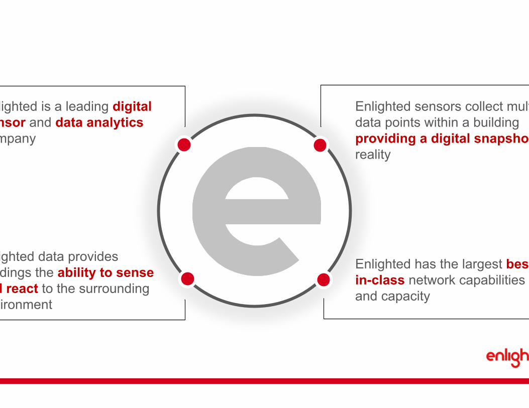
Enlighted is Different
7
Enlighted data provides buildings the ability to sense and react to the surrounding environment
Enlighted has the largest best-in-class network capabilities and capacity
Enlighted is a leading digital sensor and data analytics company
Enlighted sensors collect multiple data points within a building providing a digital snapshot of reality

8
ü All-in-one ü Patented ü Easy Design ü Futureproof ü Interoperable ü Highly Secure ü Redundant
Advanced Sensor

9
Makes Smart Buildings a Reality

10
• End User Control
• Auto Demand Response
• Color Tuning
• On-Demand HVAC
• Blind/AV Control
• Plug Load
• Conference Room
• Asset Tracking
• Indoor GPS
• Trade Area Planning
• Security
• Medical
• Emergency
• Smart Adjust Lighting


12
1,000,000 + Connected Sensors, 36 States, 8 Countries

13
COMMUNICATIONS
CONGLOMERATES
TECHNOLOGY
PHARMA
EDUCATION
BANKING
Our Customers

Enlighted Components:

Enlighted System Components
15

Enlighted System Components
16
Contact Closure

17
Durable wireless antenna
Removable bezel (for customizable painting)
Digital Motion
Photocell
Temperature Sensing
Bluetooth 4.0 BLE radio for beaconing (select models)
Threaded base (secure installation)
Local microprocessor and memory
Green or Red LEDs indicate sensor status
Sensor Details

Sensor Coverage
18
The above coverage pattern applies to Smart Sensor, Fixture Mount Sensor, Compact Sensor, and IP65 Ruggedized Sensor
The PIR technology in each Enlighted sensor utilizes digital infrared to detect movement.

High Bay Sensor Coverage
19
The above coverage pattern applies to Enlighted High Bay Sensor

Pro Tip
20

21
Enlighted Control Unit
• Interfaces with Enlighted sensor and connects to fixture Driver/Ballast
• Contains utility grade power meter to monitor fixture level consumption
• Fails to 100% on
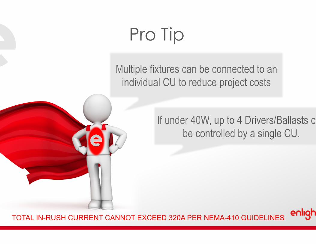
Pro Tip
22 TOTAL IN-RUSH CURRENT CANNOT EXCEED 320A PER NEMA-410 GUIDELINES

Wireless Room Control
23
• Surface mount design • Provides manual control of
Enlighted sensors
• Up to 6 programmable scenes

Plug Load Control
24
• Installs in-line with 20A circuits
• 2 legs out (1 controlled, 1 uncontrolled)
• Meters controlled an uncontrolled line

Enlighted Emergency Shunt Relay
25
• Allows for control of Emergency Fixtures
• UL Rated to comply with code requirements for egress lighting

Contact Closure
26
• Integrates the Enlighted system with other equipment throughout the building
• Four Digital Inputs (dry contacts) • I/O Interfaces

Gateway
27
• Enlighted Gateway supports up to 250 connected devices (Sensors, Wireless Switches, Plug Load Controllers)
• Wireless signal strength of roughly 150 ft. radius in open range

Energy Manager
28
• Standard Energy Manager (EM) Features
• GUI Accessible
• Configuration and Maintenance
• Profile Management
• Data Storage and Trending
• Supports up to 1,000 Connected Devices
• Wired Communication To GW • Cat-5 or Cat-6 Ethernet Connection
from Gateway to the Energy Manager

Energy Manager
29
• Standard Energy Manager (EM) Features
• GUI Accessible
• Configuration and Maintenance
• Profile Management
• Data Storage and Trending
• Supports up to 1,000 Connected Devices
• Wired Communication To GW • Cat-5 or Cat-6 Ethernet Connection
from Gateway to the Energy Manager

Energy Manager
30
• Standard Energy Manager (EM) Features
• GUI Accessible
• Configuration and Maintenance
• Profile Management
• Data Storage and Trending
• Supports up to 7,000 Connected Devices
• Wired Communication To GW • Cat-5 or Cat-6 Ethernet Connection
from Gateway to the Energy Manager
Energy Manager
31
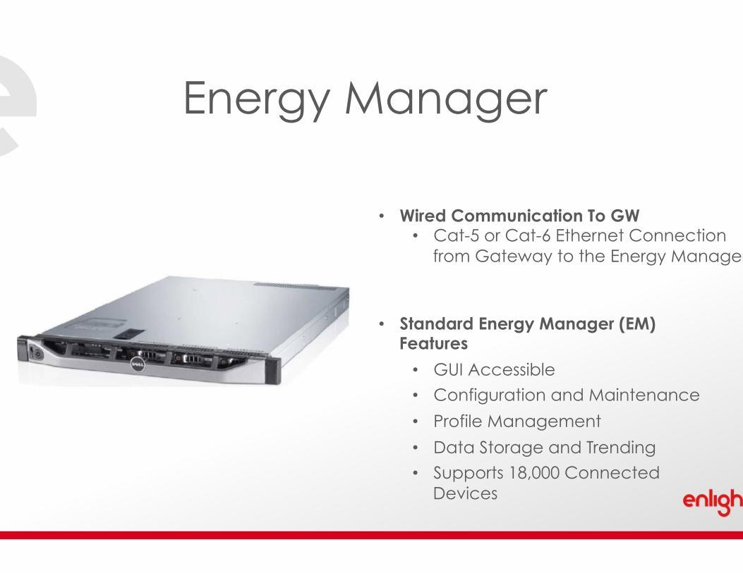
• Standard Energy Manager (EM) Features
• GUI Accessible
• Configuration and Maintenance
• Profile Management
• Data Storage and Trending
• Supports 18,000 Connected Devices
• Wired Communication To GW • Cat-5 or Cat-6 Ethernet Connection
from Gateway to the Energy Manager

Energy Manager
32
• Standard Energy Manager (EM) Features
• GUI Accessible
• Configuration and Maintenance
• Profile Management
• Data Storage and Trending
• Supports 3,000 to 5,000 connected devices per server
• Wired Communication To GW • Cat-5 or Cat-6 Ethernet Connection
from Gateway to the Energy Manager

Pro Tip
33
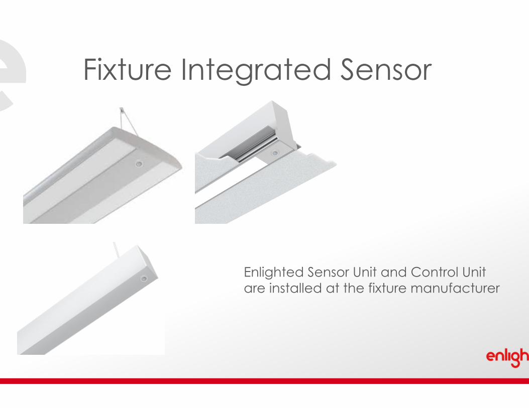
Fixture Integrated Sensor
34
Enlighted Sensor Unit and Control Unit are installed at the fixture manufacturer

Enlighted CAD/Bluebeam Symbols

Enlighted CAD/Bluebeam Symbols
36

37
Enlighted CAD/Bluebeam Symbols

Enlighted Component Layout

Emergency Fixtures
39
Fixture Integrated Sensors w/ UL924 Relay
Field Install Sensors w/ UL924 Relay

Indirect/Direct Fixtures
40
Indirect/Direct fixtures have luminaires facing upward and downward on the fixture. To enable individual functionality on an indirect/direct fixture a separate control unit and sensor are required to control the upward facing light as well as the downward facing light. Note each 4’ fixture in the drawing below has 2 SUs and CUs per fixture.
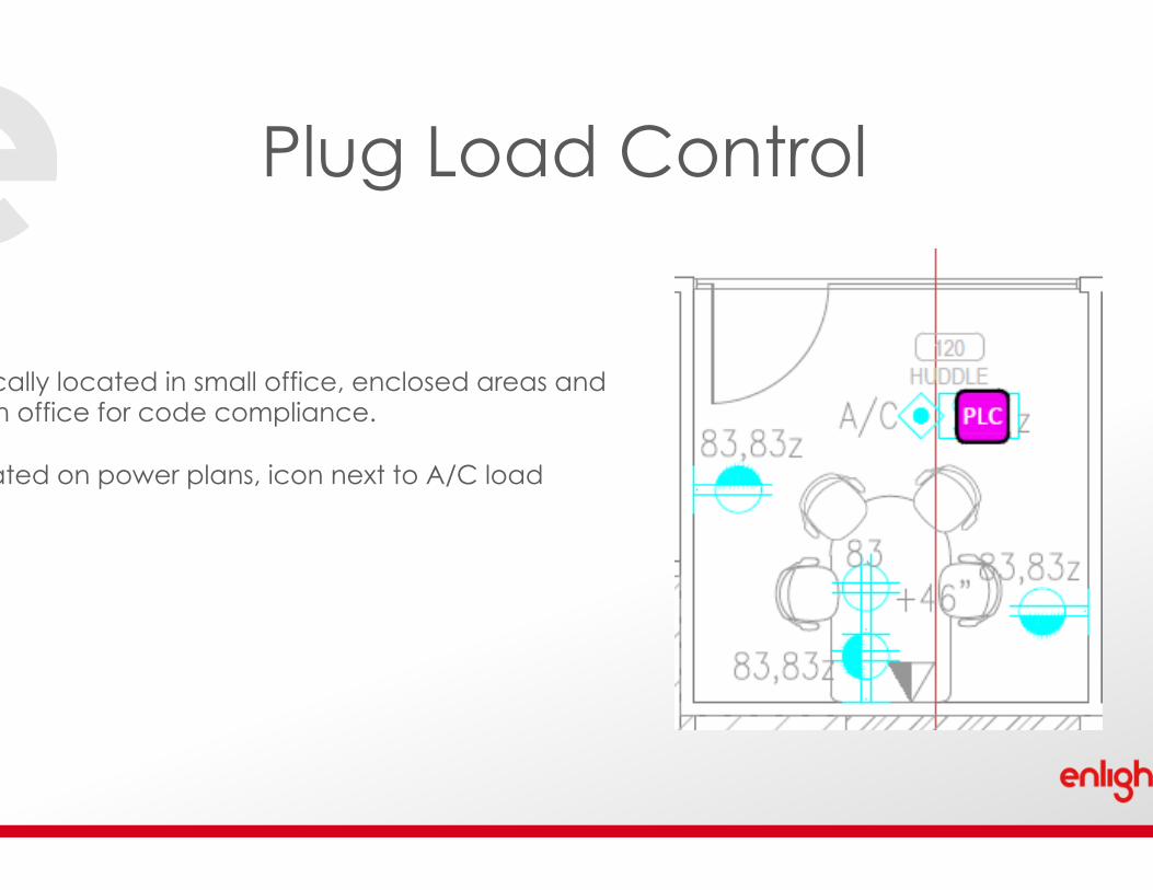
Plug Load Control
41
Typically located in small office, enclosed areas and open office for code compliance. Located on power plans, icon next to A/C load

Private Office
42
• Two 2’ x 4’ recessed troffer fixtures grouped with 1 compact sensor and control unit
• Grouping indicated by blue line
• Wireless Room Control located near entry
• Sensor located to detected movement throughout the space
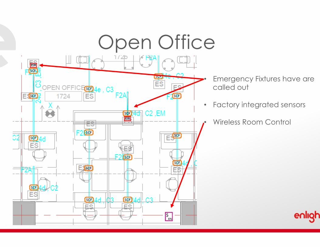
Open Office
43
• Emergency Fixtures have are called out
• Factory integrated sensors
• Wireless Room Control

Conference Room
44
• Factory integrated sensors to reduce
field install labor
• Wireless Room Control to provide multiple pre-set scenes for presentation mode, etc.

Restroom
45
• Multiple recessed can fixtures are grouped together with one sensor and control unit
• Grouping indicated by blue line connecting fixtures
• Sensors located near entry
and strategically in the space to provide coverage based on usage of the room

Hallway/Corridor
46
• Multiple recessed can fixtures are grouped together with one sensor and control unit
• Grouping indicated by blue line connecting fixtures
• Sensors located strategically to provide coverage based on usage
• Emergency fixtures have UL924 Shunt Relay added

Kitchen
47
• Multiple recessed can fixtures are grouped together with one sensor and control unit
• Grouping indicated by blue line connecting fixtures
• Wireless Switch located near entry
• Sensors located strategically to provide coverage based on usage of the room


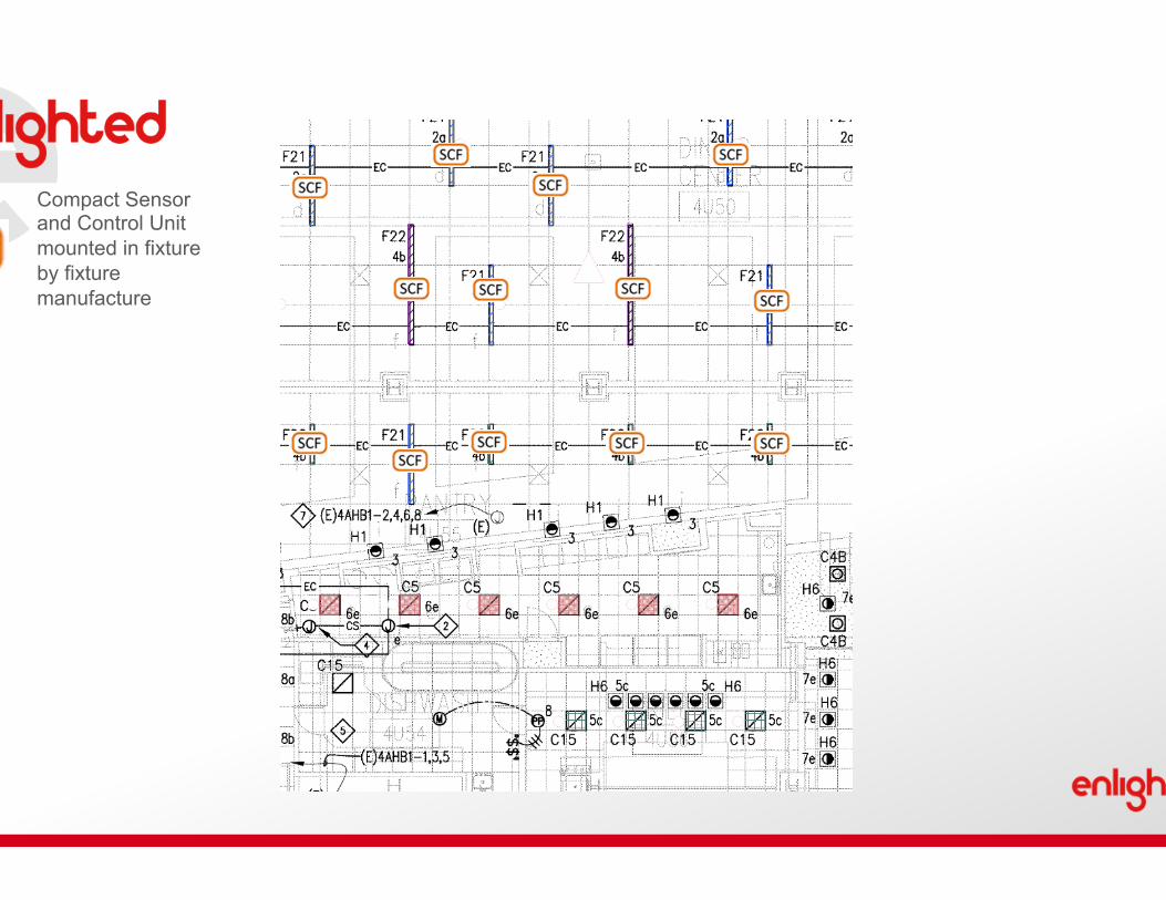
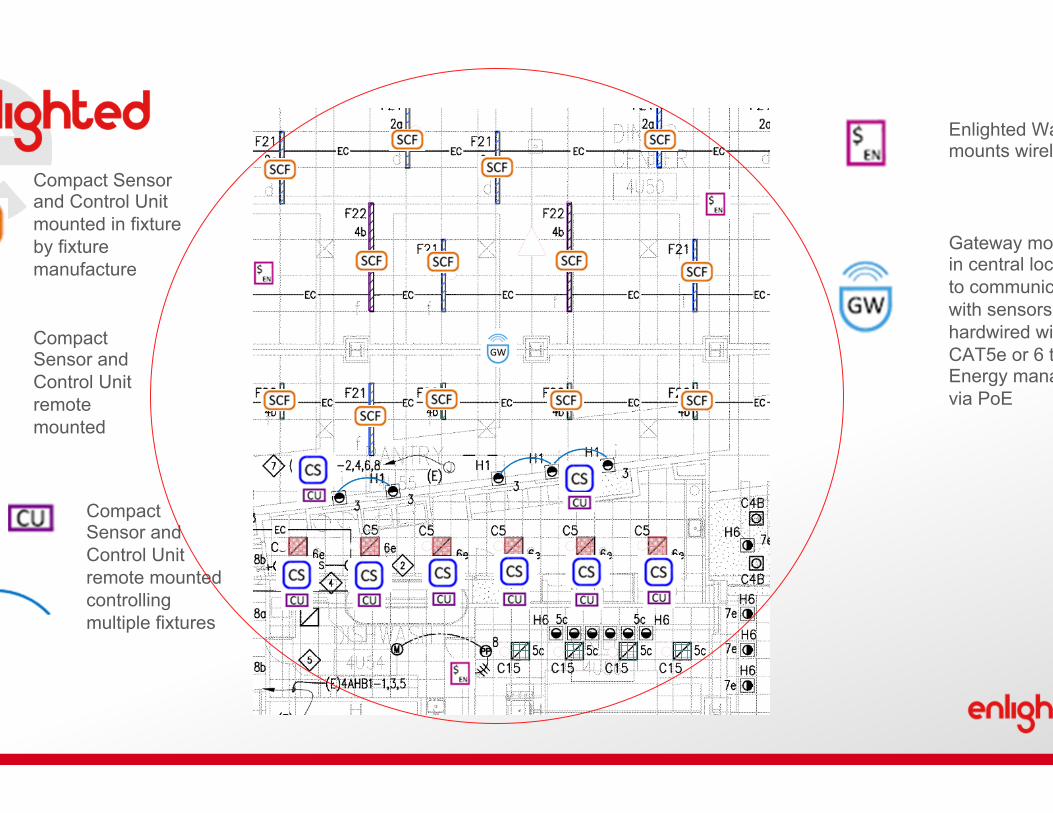
Compact Sensor and Control Unit mounted in fixture by fixture manufacture
Compact Sensor and Control Unit mounted in fixture by fixture manufacture

Compact Sensor and Control Unit mounted in fixture by fixture manufacture
Compact Sensor and Control Unit remote mounted
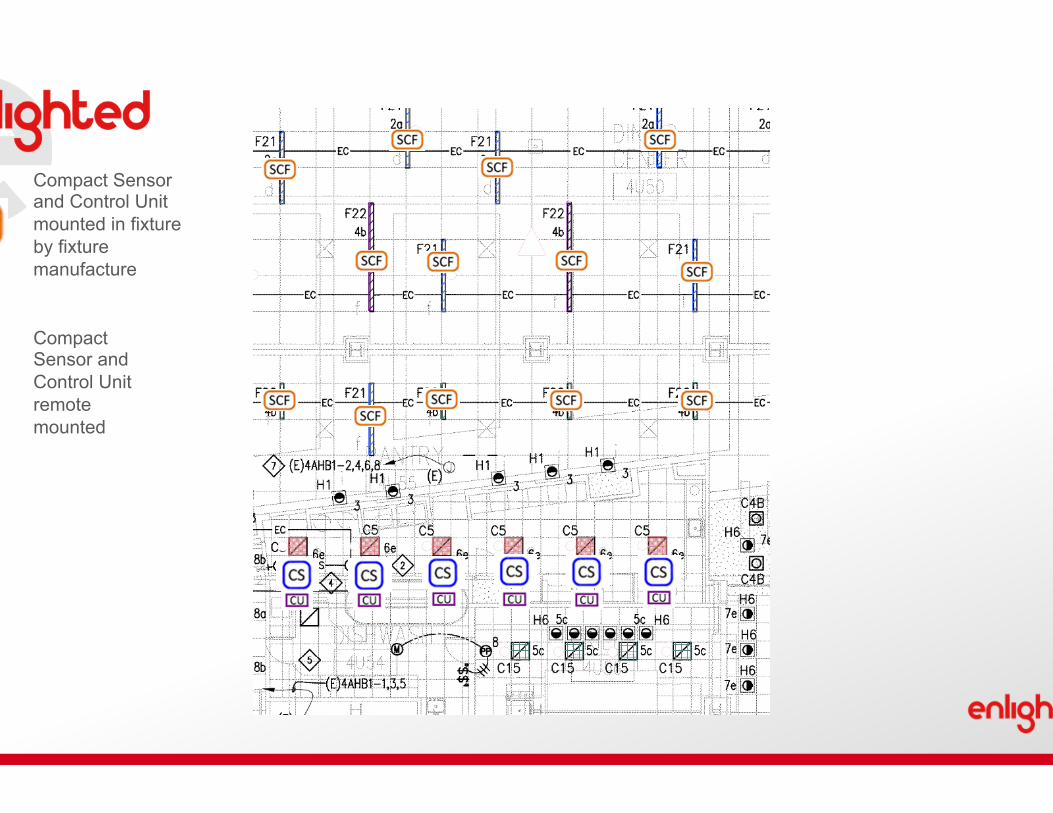
Compact Sensor and Control Unit mounted in fixture by fixture manufacture
Compact Sensor and Control Unit remote mounted

Compact Sensor and Control Unit mounted in fixture by fixture manufacture
Compact Sensor and Control Unit remote mounted
Compact Sensor and Control Unit remote mounted controlling multiple fixtures

Compact Sensor and Control Unit mounted in fixture by fixture manufacture
Compact Sensor and Control Unit remote mounted
Compact Sensor and Control Unit remote mounted controlling multiple fixtures

Compact Sensor and Control Unit mounted in fixture by fixture manufacture
Compact Sensor and Control Unit remote mounted
Compact Sensor and Control Unit remote mounted controlling multiple fixtures
Enlighted Wall Control mounts wirelessly

Compact Sensor and Control Unit mounted in fixture by fixture manufacture
Compact Sensor and Control Unit remote mounted
Compact Sensor and Control Unit remote mounted controlling multiple fixtures
Enlighted Wall Control mounts wirelessly

Compact Sensor and Control Unit mounted in fixture by fixture manufacture
Compact Sensor and Control Unit remote mounted
Compact Sensor and Control Unit remote mounted controlling multiple fixtures
Enlighted Wall Control mounts wirelessly
Gateway mounted in central location to communicate with sensors and hardwired with CAT5e or 6 to Energy manager via PoE
Enlighted EM and PoE switch mounted in Enlighted Enclosure

Title 24 Design Considerations

Enlighted and Title 24
63
Oh my God Title 24 is so complicated what am I to do

64
Energy Codes – 5 Parts Required - Sensor, Controller, Wall Control, Plug Load Relay, Energy Manager (gateway and PoE switch to make it work) Fire Codes – Contact Closure Unit – Drive all or selected loads to full
Emergency Codes – UL924 Shunt Load Relay Sequence of Operations – What profile is needed for what room
Code Compliant out of Box
65
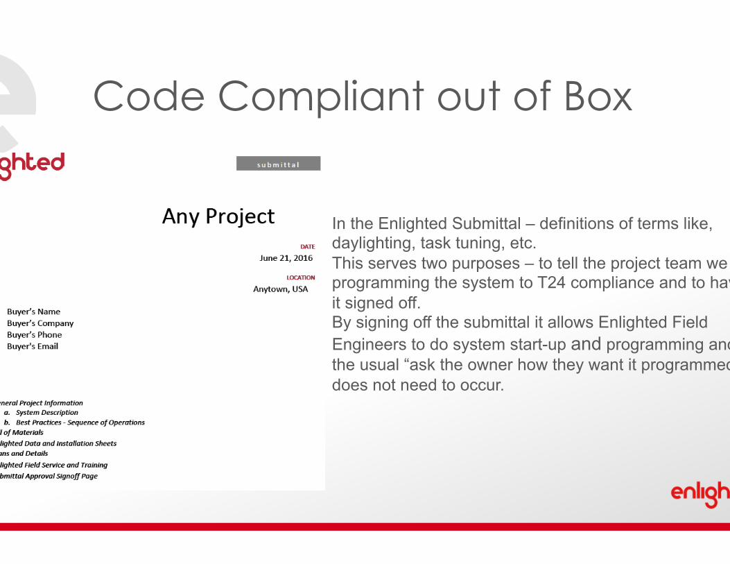
In the Enlighted Submittal – definitions of terms like, daylighting, task tuning, etc. This serves two purposes – to tell the project team we are programming the system to T24 compliance and to have it signed off. By signing off the submittal it allows Enlighted Field Engineers to do system start-up and programming and the usual “ask the owner how they want it programmed” does not need to occur.
Code Compliant out of Box

66
Sequence of Operations

67
Occupancy Sensor 130.1(c)
Photo Sensor 130.1(d)
Temperature
Sensor can tell time
On by wall control, automatic shutoff (vacancy) On by Sensor off by Sensor (occupancy) On by time, unoccupied dim to < 50% (part-off) On by wall control, lower to 20% when unoccupied, auto shutoff after hours
Skylight, Primary, Secondary Zones Temperature – not required for lighting
Programming stored in sensor. Day Profile – unoccupied dim to 20%, 50% Night Profile – unoccupied turn off
Sensors

68
Control Unit 130.1(b,d,e)
Power Meter in CU 130.1(e)
Full Range 0-10v dimming LV cable to sensor (best if Sensor and CU installed in fixture)
Allows for ADR testing without using any additional tools
Control Unit

69
130.1(a) Area Controls On Off 130.1(b) Multi-Level Raise Lower Wireless requires no power. Communicates with up to 100 sensors. Required in enclosed areas > 100 sq ft. Full range dimming with Enlighted Sensor and CU.
Wireless Room Control
70
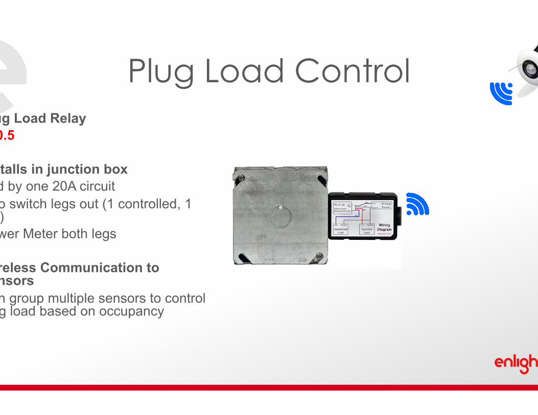
Plug Load Relay 130.5 Installs in junction box Fed by one 20A circuit Two switch legs out (1 controlled, 1 not) Power Meter both legs Wireless Communication to Sensors Can group multiple sensors to control plug load based on occupancy
Plug Load Control

71
Energy Manager 130.1(e)
Reporting Functions
BACnet capability Programming and Configuration of Profiles Reporting Functions Power Usage Occupied or Unoccupied Timeout Daylight Usage
Energy Manager

72
Simulating a demand response for Acceptance Testing is easy using Enlighted. FIRST! Enlighted is ADR 2.0 compliant. So if the building owner wants to sign up with the local utility for huge energy savings – your ready to go! To test ADR go the ADR screen and initiate DR level 1. The system will reduce the lighting by 15%. Wait 15 minutes and run a report. By using the utilty grade power meters in the CU you can identify savings in rooms, and the whole building energy savings. SAVE A DAY OF TESTING AND CALCULATIONS
Auto Demand Response

73
You see, Enlighted really did make it that simple to comply
That Was Easy

www.enlightedinc.com
Enlighted. Changes Everything. Thank You

Contacts
75
Ben.Lyon@ enlightedinc.com
Ben Lyon Director, Customer Success
Phil.Hall@ enlightedinc.com
Phil Hall Director, Code Compliance Programs Joaquin.Ibarra@
enlightedinc.com
Joaquin Ibarra Design Manager
David Jackson Sr. Director, OEM Sales
David.Jackson@ enlightedinc.com


