Page 1
DESIGN AND FABRICATION OF WATT AND PORTER
GOVERNOR
A PROJECT REPORT
Submitted by
B.JAGADISH
S.KAUSHIK RAJALINGAM
J.KENNETH
R.PRASANTH
In partial fulfillment for the award of the degree
Of
BACHELOR OF ENGINEERING
In
MECHANICAL ENGINEERING
SRI SAIRAM ENGINEERING COLLEGE
ANNA UNIVERSITY: CHENNAI 600025
April 2011
Page 2
ANNA UNIVERSITY: CHENNAI 600 025
BONAFIDE CERTIFICATE
Certified that this project report “DESIGN AND FABRICATION OF WATT
AND PORTER GOVERNOR “ is the bonafide work of “B.JAGADISH
(41908114032), S.KAUSHIK RAJALINGAM (41908114039), J.KENNETH
(41908114040), R.PRASANTH (41908114059)”, who carried out the project
work under my supervision.
SIGNATURE SIGNATURE
Dr. A. RAJENDRA PRASAD V.M.MANICKAVASAGAM
HEAD OF THE DEPARTMENT, SUPERVISOR,
Department of Mechanical Engineering, Assistant Professor,
Sri Sairam Engineering College, Department of Mechanical Engineering,
Chennai: 600 044. Sri Sairam Engineering College,
Chennai: 600 044.
INTERNAL EXAMINER EXTERNAL EXAMINER
Page 3
i
ACKNOWLEDGEMENT
We here by acknowledge our sincere gratitude to our beloved Chairman
Thiru. MJF.Ln.LEO MUTHU for the help and advice he has shared upon us
and providing us with large facilities.
We are thankful to our beloved CEO, Mr.J.SAI PRAKASH and our
Secretary Mr.M.VASU for providing the opportunity to showcase our skills
and knowledge.
We express our sincere thanks to our Director and Professor
Mr.V.R.RAJAMANICKAM, and our Principal Dr. C.V. JAYAKUMAR for
having given us spontaneous and whole hearted support for completing the
project.
We are grateful to Dr.A.RAJENDRA PRASAD, Head of the
Department, Dean-R&D for his constant support and his valuable guidance
during the entire course of our project.
We are greatly indebted to Mr. V.M. MANICKAVASAGAM, our project
guide, Assistant Professor, Department of Mechanical Engineering, for his
valuable guidance in this endeavor.
We are thankful to all non-teaching staffs for their help in manufacturing and
Fabrication of the components.
We express our gratitude to all other faculty members, seniors and our
classmates who have constantly encouraged and helped us in completing this
project successfully. We thank all persons who have directly or indirectly made
their contribution in this project.
Page 4
ii
ABSTRACT
The aim of our project is to develop prototype of a product “watt and
porter governor”. The function of the governor is to maintain the speed of an
engine within specified limits whenever there is a variation of load. It is a
dynamic device done in the field of manufacturing technology. It's rather
inexpensive and can be used in almost all vehicles.
The governor generally consists of a sleeve which is attached to a throttle
valve. When the sleeve reaches its lowest position, the engine should develop
maximum power. On the sudden removal of load its sleeve should reach the top
most position at once. Its sleeve should float at some intermediate position
under normal operating conditions.
When the load on an engine increases or decreases, obviously its speed
will respectively decrease or increase to the extent of variation of load. This
variation of speed has to be controlled by the governor, within small limits of
the mean speed. This necessities that when the load increases and consequently
the speed decreases, the supply of fuel to one engine has to be increased
accordingly, to compensate for the loss of the speed, so as to bring back the
speed close to the mean speed. Conversely when the load decreases, and the
speed increase, the supply of fuel has to be reduced. This implies that the
governor should have its mechanism working in such a way, that the supply of
fuel is automatically regulated according to the load requirement for
maintaining approximately a constant speed.
Page 5
iii
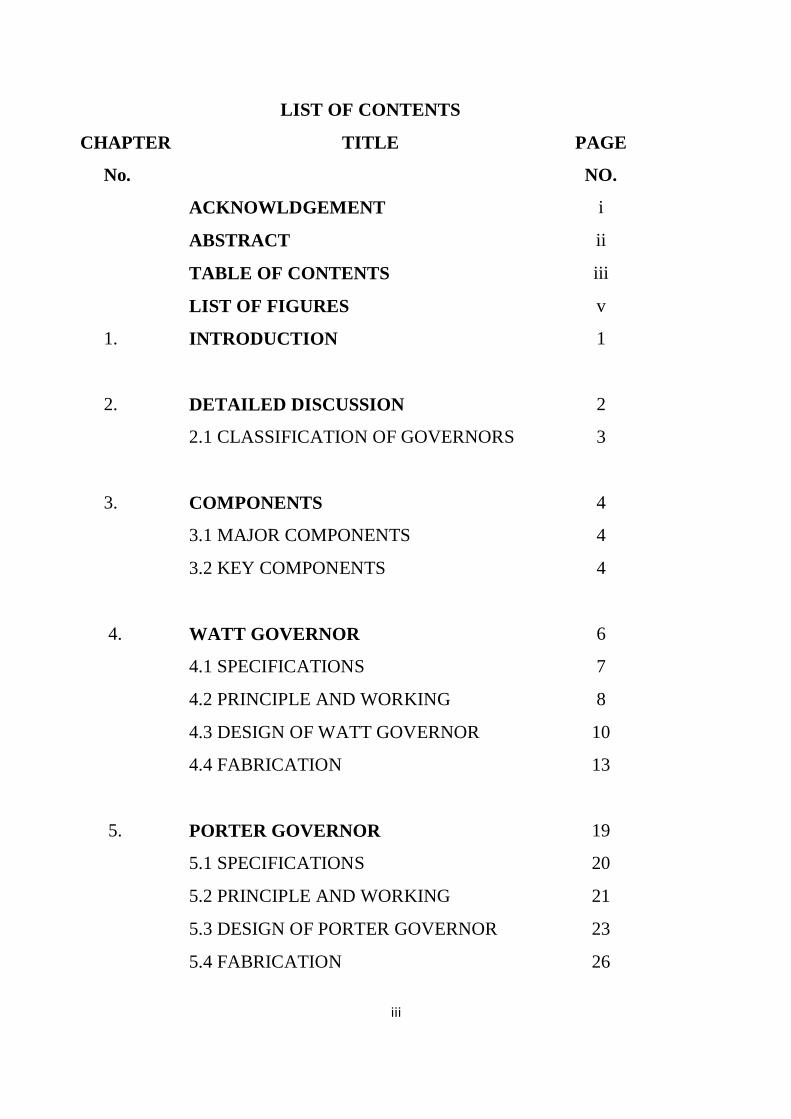
LIST OF CONTENTS
CHAPTER
No.
TITLE PAGE
NO.
ACKNOWLDGEMENT i
ABSTRACT ii
TABLE OF CONTENTS iii
LIST OF FIGURES v
1. INTRODUCTION 1
2. DETAILED DISCUSSION 2
2.1 CLASSIFICATION OF GOVERNORS 3
3. COMPONENTS 4
3.1 MAJOR COMPONENTS 4
3.2 KEY COMPONENTS 4
4. WATT GOVERNOR 6
4.1 SPECIFICATIONS 7
4.2 PRINCIPLE AND WORKING 8
4.3 DESIGN OF WATT GOVERNOR 10
4.4 FABRICATION 13
5. PORTER GOVERNOR 19
5.1 SPECIFICATIONS 20
5.2 PRINCIPLE AND WORKING 21
5.3 DESIGN OF PORTER GOVERNOR 23
5.4 FABRICATION 26
Page 6
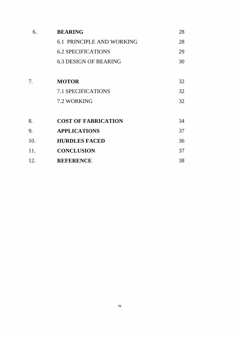
iv
6. BEARING 28
6.1 PRINCIPLE AND WORKING 28
6.2 SPECIFICATIONS 29
6.3 DESIGN OF BEARING 30
7. MOTOR 32
7.1 SPECIFICATIONS 32
7.2 WORKING 32
8. COST OF FABRICATION 34
9. APPLICATIONS 37
10. HURDLES FACED 36
11. CONCLUSION 37
12. REFERENCE 38
Page 7
v
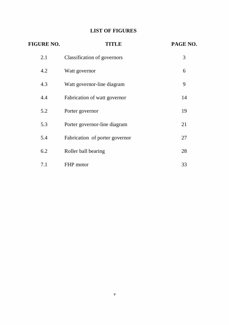
LIST OF FIGURES
FIGURE NO. TITLE PAGE NO.
2.1 Classification of governors 3
4.2 Watt governor 6
4.3 Watt governor-line diagram 9
4.4 Fabrication of watt governor 14
5.2 Porter governor 19
5.3 Porter governor-line diagram 21
5.4 Fabrication of porter governor 27
6.2 Roller ball bearing 28
7.1 FHP motor 33
Page 8
1
CHAPTER 1
INTRODUCTION
A governor, or speed limiter, is a device used to measure and regulate the
speed of a machine, such as an engine. A classic example is the centrifugal
governor, also known as the watt or fly-ball governor, which uses weights
mounted on spring-loaded arms to determine how fast a shaft is spinning, and
then uses proportional control to regulate the shaft speed.
Centrifugal governors were used to regulate the distance and pressure
between millstones in windmills since the 17th century. Early steam engines
employed a purely reciprocating motion, and were used for pumping water – an
application that could tolerate variations in the working speed. It was not until
the Scottish engineer James Watt introduced the rotative steam engine, for
driving factory machinery, that a constant operating speed became necessary.
Between the years 1775 and 1800, Watt, in partnership with industrialist
Matthew Bolton, produced some 500 rotati-ve beam engines. At the heart of
these engines was Watt‟s self-designed "conical pendulum" governor: a set of
revolving steel balls attached to a vertical spindle by link arms, where the
controlling force consists of the weight of the balls.
Building on Watt‟s design was American engineer Willard Gibbs who in
1872 theoretically analyzed Watt‟s conical pendulum governor from a
mathematical energy balance perspective. During his graduate school years at
Yale University, Gibbs observed that the operation of the device in practice was
beset with the disadvantages of sluggishness and a tendency to overcorrect for
the changes in speed it was supposed to control.
Page 9
2
CHAPTER 2
CLASSIFICATION
(i) A governor, or speed limiter, is a device used to measure and regulate
the speed of a machine, such as an engine. A classic example is the
centrifugal governor, also known as the Watt governor, which uses weights
mounted on loaded arms to determine how fast a shaft is spinning, and then
uses proportional control to regulate the shaft speed. The watt governor is
named after James Watt who used it for steam engines. James Watt designed
his first governor in 1788 following a suggestion from his business partner
Matthew Boulton. It was a conical pendulum governor and one of the final
series of innovations Watt had employed for steam engines. James Watt
never claimed the centrifugal governor to be an invention of his own.
Centrifugal governors were used to regulate the distance and pressure
between millstones in windmills since the 17th century. It is therefore a
misunderstanding that James Watt is the inventor of this device.
(ii)A giant statue of Watt's governor stands at Smethwick in the English
West Midlands. It is known as the fly ball governor.
(iii)Another kind of centrifugal governor consists of a pair of masses on a
spindle inside a cylinder, the masses or the cylinder being coated with pads,
somewhat like a drum brake. This is used in a spring-loaded record player
and a spring-loaded telephone dial to limit the speed.
(iv)The major advantage of the governors is rather inexpensive and
highly efficient.
Page 10
3
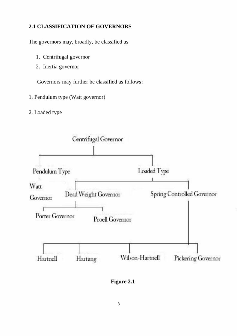
2.1 CLASSIFICATION OF GOVERNORS
The governors may, broadly, be classified as
1. Centrifugal governor
2. Inertia governor
Governors may further be classified as follows:
1. Pendulum type (Watt governor)
2. Loaded type
Figure 2.1
Page 11
4
CHAPTER 3
COMPONENTS
3.1 MAJOR COMPONENTS:
Frame:
A frame is a structural system that supports other components of a
physical construction.
Shaft/Spindle:
A spindle is a rotating axis of the machine, which often has a shaft at
its heart. The shaft itself is called a spindle, but also, in shop-floor practice, the
word often is used metonymically to refer to the entire rotary unit, including not
only the shaft itself, but its bearings and anything attached to it.
Motor:
An electric motor converts electrical energy into mechanical energy.
Most electric motors operate through interacting magnetic fields and current-
carrying conductors to generate force, although electrostatic motors use
electrostatic forces.
3.2 KEY COMPONENTS:
SLEEVE:
The sleeve valve is a type of valve mechanism for piston engines,
distinct from the more common poppet valve.
Page 12
5
BEARING:
A bearing is a device to allow constrained relative motion between
two or more parts, typically rotation or linear movement. Bearings may be
classified broadly according to the motions they allow and according to their
principle of operation as well as by the directions of applied loads they can
handle.
RULER:
A ruler, sometimes called a rule or line gauge, is an instrument used in
geometry, technical drawing, printing and engineering/building to measure
distances and/or to rule straight lines.
Page 13
6
CHAPTER 4
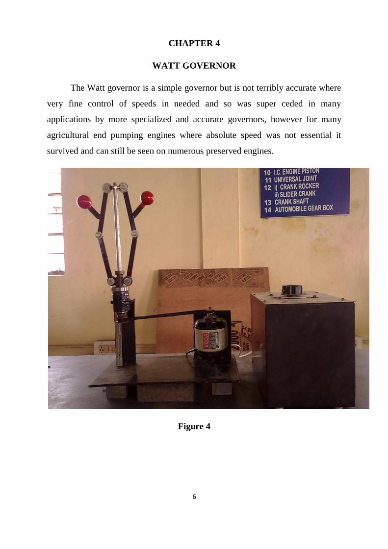
WATT GOVERNOR
The Watt governor is a simple governor but is not terribly accurate where
very fine control of speeds in needed and so was super ceded in many
applications by more specialized and accurate governors, however for many
agricultural end pumping engines where absolute speed was not essential it
survived and can still be seen on numerous preserved engines.
Figure 4
Page 14
7
4.1 SPECIFICATIONS:
Basic specifications:
(i) Power supply
(ii) 230 V AC, Single phase, Variac.
Materials:
(i) Spindle: Stainless Steel
(ii) Fly balls: Cast Iron
(iii) Arms: Stainless steel
(iv) Frame: Mild steel
Governor Mechanism:
Watt Governor
Page 15
8
4.1 Principle:
The function of the governor is to regulate the mean speed of an engine,
when there are variations in the load .e.g. when the load on an engine increases,
its speed decreases therefore it becomes necessary to increases the supply of
working fluid .On the other hand, when the load on the engine decreases, its
speed increases and thus less working fluid is required. The governor
automatically controls the supply of the working fluid to the engine with the
varying load conditions and keeps the mean speed within certain limits.
A little consideration will show ,that when the load increases ,the
configuration of the governor changes and a valve is moved to increase the
supply of the working fluid ; conversely , when the load decreases , the engine
speed increases and the governor decreases the supply of working fluid.
Working:
Probably the most widely used governor in the early days; it is named
the watt governor because James Watt applied it to his early beam engines. He
did not however invent it as it had been in use on wind and water mills many
years before this. A belt or gearing from the engine crankshaft drives the input
shaft 'm' causing the bevel gears 'l' to revolve and in turn rotate the vertical shaft
'a'. The bracket 'b' at the top of 'a' supports two arms 'c' which are pivoted at the
top, at the end of the arms are two very heavy metal weights 'B' partway along
the arms 'c' are fixed two pivoted link arms‟d‟ which link to a collar 'c' which
rotates with them but is able to slide up and down shaft „a‟.
Page 16
9
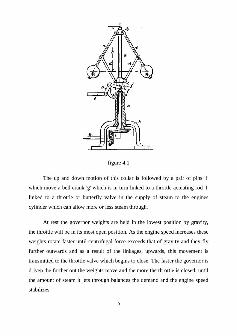
figure 4.1
The up and down motion of this collar is followed by a pair of pins 'f'
which move a bell crank 'g' which is in turn linked to a throttle actuating rod 'I'
linked to a throttle or butterfly valve in the supply of steam to the engines
cylinder which can allow more or less steam through.
At rest the governor weights are held in the lowest position by gravity,
the throttle will be in its most open position. As the engine speed increases these
weights rotate faster until centrifugal force exceeds that of gravity and they fly
further outwards and as a result of the linkages, upwards, this movement is
transmitted to the throttle valve which begins to close. The faster the governor is
driven the further out the weights move and the more the throttle is closed, until
the amount of steam it lets through balances the demand and the engine speed
stabilizes.
Page 17
10
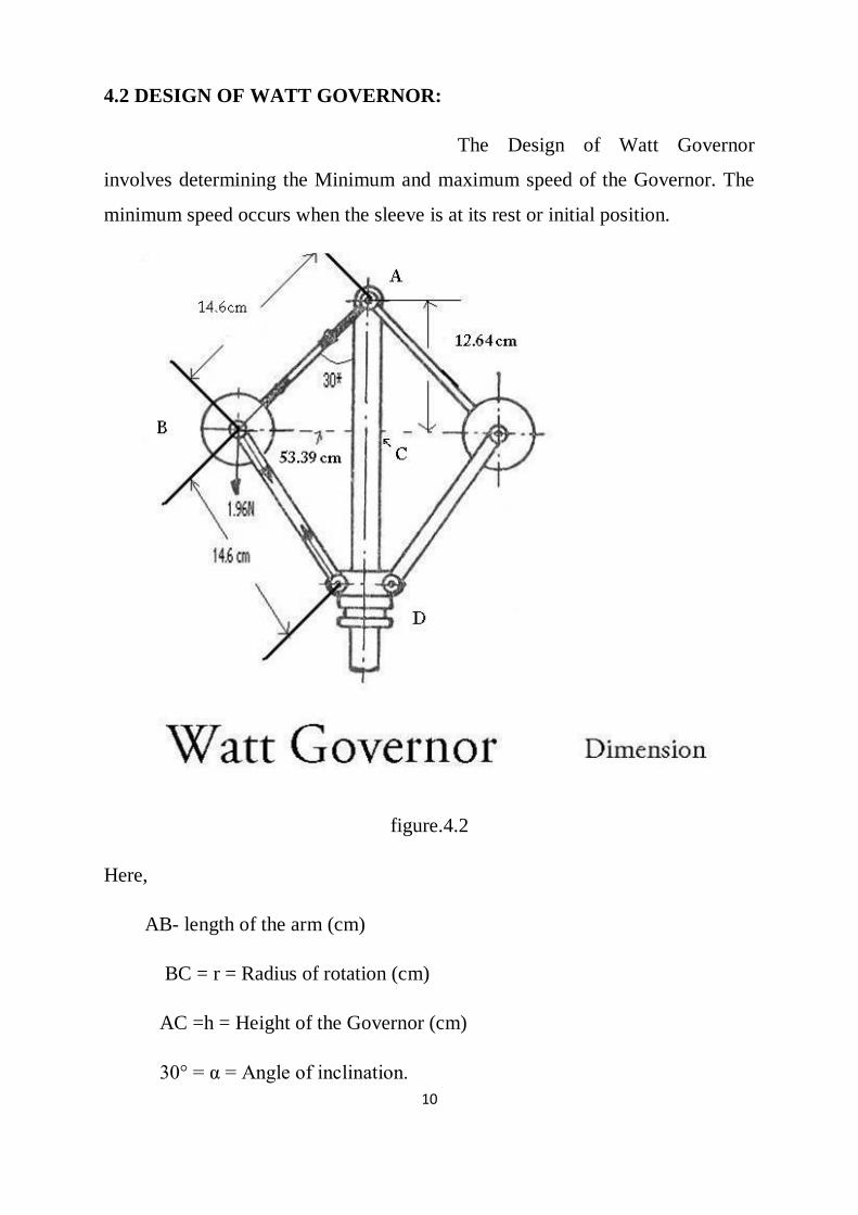
4.2 DESIGN OF WATT GOVERNOR:
The Design of Watt Governor
involves determining the Minimum and maximum speed of the Governor. The
minimum speed occurs when the sleeve is at its rest or initial position.
figure.4.2
Here,
AB- length of the arm (cm)
BC = r = Radius of rotation (cm)
AC =h = Height of the Governor (cm)
30° = α = Angle of inclination.
Page 18
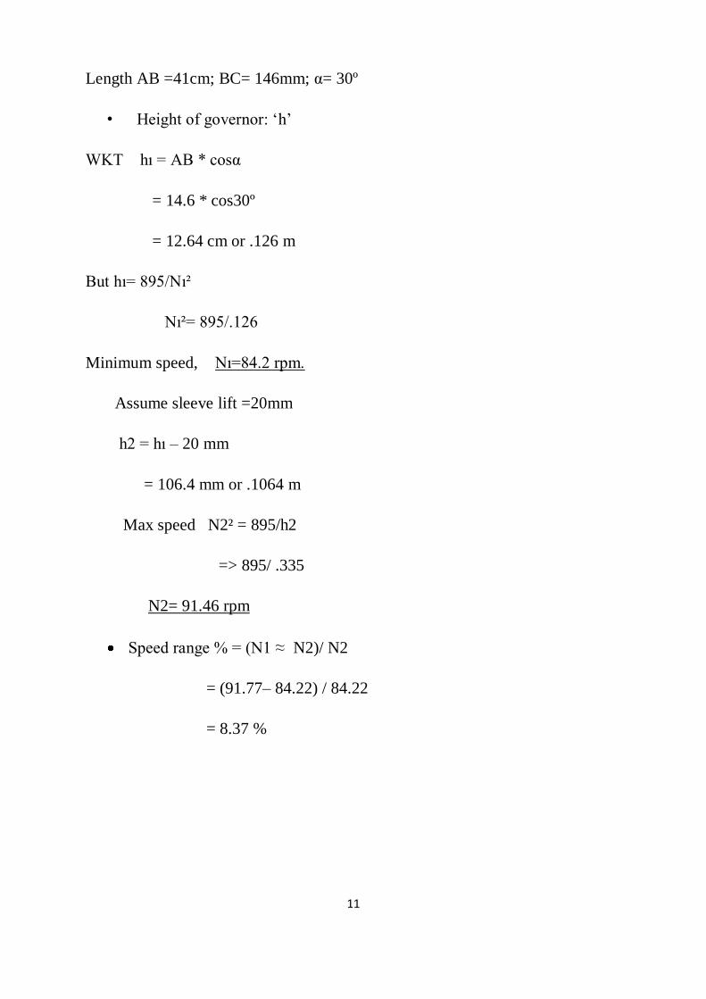
11
Length AB =41cm; BC= 146mm; α= 30º
• Height of governor: „h‟
WKT hı = AB * cosα
= 14.6 * cos30º
= 12.64 cm or .126 m
But hı= 895/Nı²
Nı²= 895/.126
Minimum speed, Nı=84.2 rpm.
Assume sleeve lift =20mm
h2 = hı – 20 mm
= 106.4 mm or .1064 m
Max speed N2² = 895/h2
=> 895/ .335
N2= 91.46 rpm
Speed range % = (N1 ≈ N2)/ N2
= (91.77– 84.22) / 84.22
= 8.37 %
Page 19
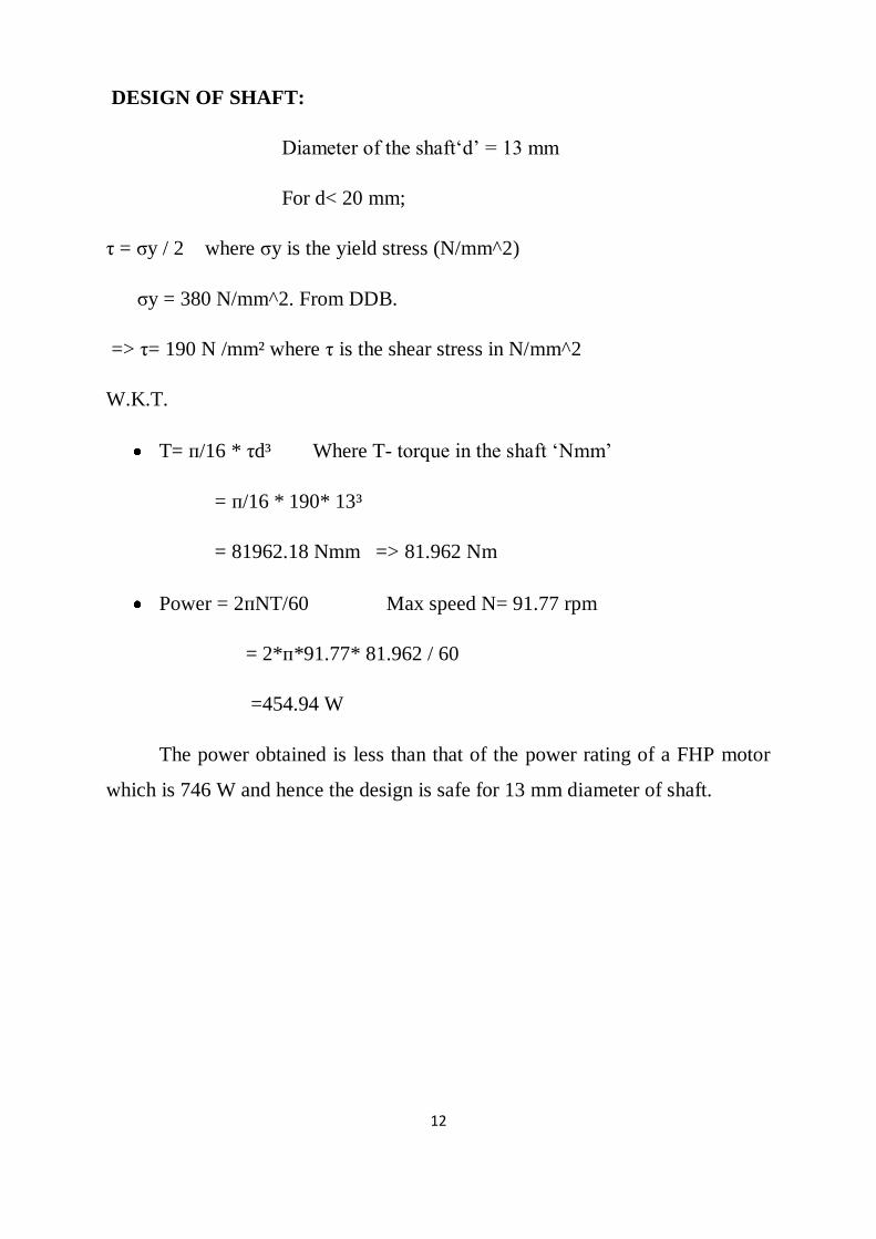
12
DESIGN OF SHAFT:
Diameter of the shaft„d‟ = 13 mm
For d< 20 mm;
τ = σy / 2 where σy is the yield stress (N/mm^2)
σy = 380 N/mm^2. From DDB.
=> τ= 190 N /mm² where τ is the shear stress in N/mm^2
W.K.T.
T= п/16 * τd³ Where T- torque in the shaft „Nmm‟
= п/16 * 190* 13³
= 81962.18 Nmm => 81.962 Nm
Power = 2пNT/60 Max speed N= 91.77 rpm
= 2*п*91.77* 81.962 / 60
=454.94 W
The power obtained is less than that of the power rating of a FHP motor
which is 746 W and hence the design is safe for 13 mm diameter of shaft.
Page 20
13
4.3 FABRICATION OF WATT GOVERNOR
Fabrication as an industrial term refers to building metal structures by
cutting, bending and assembling.
The Fabrication of Watt Governor involves:
i. Turning operation in lathe. (spindle)
ii. Threading operation in lathe machine.( Spindle)
iii. Drilling holes in watt arms, vertical plate and frame.
iv. Step turning of sleeve.
v. Cylindrical grinding for good surface finish.
vi. Welding operation. (Frame and Arms).
vii. Gas cutting of frame.
Page 21
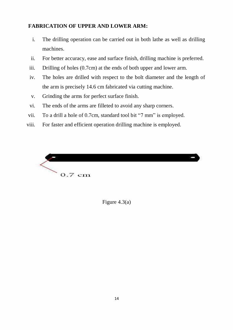
14
FABRICATION OF UPPER AND LOWER ARM:
i. The drilling operation can be carried out in both lathe as well as drilling
machines.
ii. For better accuracy, ease and surface finish, drilling machine is preferred.
iii. Drilling of holes (0.7cm) at the ends of both upper and lower arm.
iv. The holes are drilled with respect to the bolt diameter and the length of
the arm is precisely 14.6 cm fabricated via cutting machine.
v. Grinding the arms for perfect surface finish.
vi. The ends of the arms are filleted to avoid any sharp corners.
vii. To a drill a hole of 0.7cm, standard tool bit “7 mm” is employed.
viii. For faster and efficient operation drilling machine is employed.
Figure 4.3(a)
Page 22
15
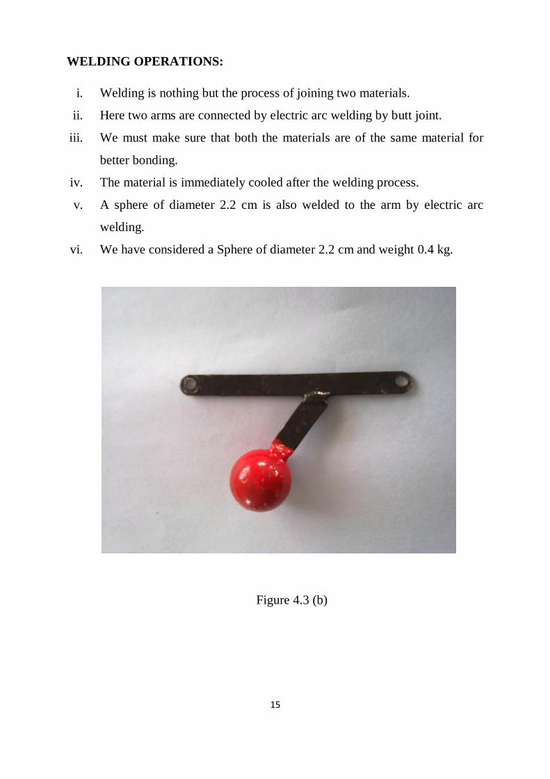
WELDING OPERATIONS:
i. Welding is nothing but the process of joining two materials.
ii. Here two arms are connected by electric arc welding by butt joint.
iii. We must make sure that both the materials are of the same material for
better bonding.
iv. The material is immediately cooled after the welding process.
v. A sphere of diameter 2.2 cm is also welded to the arm by electric arc
welding.
vi. We have considered a Sphere of diameter 2.2 cm and weight 0.4 kg.
Figure 4.3 (b)
Page 23
16
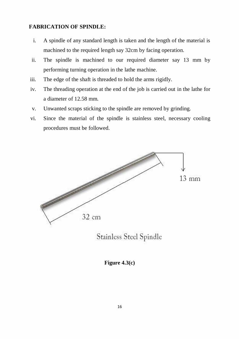
FABRICATION OF SPINDLE:
i. A spindle of any standard length is taken and the length of the material is
machined to the required length say 32cm by facing operation.
ii. The spindle is machined to our required diameter say 13 mm by
performing turning operation in the lathe machine.
iii. The edge of the shaft is threaded to hold the arms rigidly.
iv. The threading operation at the end of the job is carried out in the lathe for
a diameter of 12.58 mm.
v. Unwanted scraps sticking to the spindle are removed by grinding.
vi. Since the material of the spindle is stainless steel, necessary cooling
procedures must be followed.
Figure 4.3(c)
Page 24
17
FABRICATION OF FRAME
i. The frame has to withstand heavy load of the spindle set up as well as the
motor. So the frame must be selected in such a way to withstand heavy
load to avoid any disturbance.
ii. A MS base plate is chosen as the frame to avoid breakage and also
prevent noise.
iii. The frame is cut to the required dimensions using gas cutting process.
iv. The distance between the spindle setup and motor centre is calibrated
with the belt provided.
v. Two projections are brought out from the base plate, welded, one for the
spindle set up and the other for the motor.
vi. The frame is tightened with the help of bolt and nuts for rigid support.
vii. Grinding is undertaken for a smooth surface finish.
figure 4.3(d)
Page 25
18
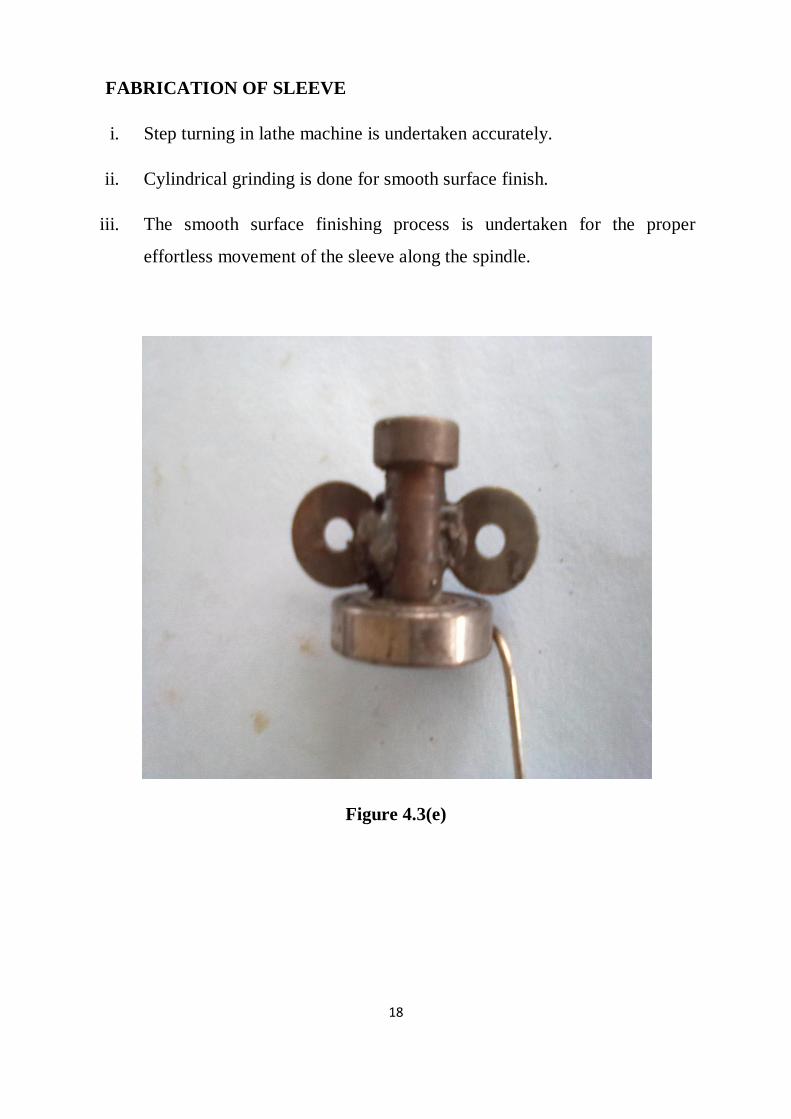
FABRICATION OF SLEEVE
i. Step turning in lathe machine is undertaken accurately.
ii. Cylindrical grinding is done for smooth surface finish.
iii. The smooth surface finishing process is undertaken for the proper
effortless movement of the sleeve along the spindle.
Figure 4.3(e)
Page 26
19
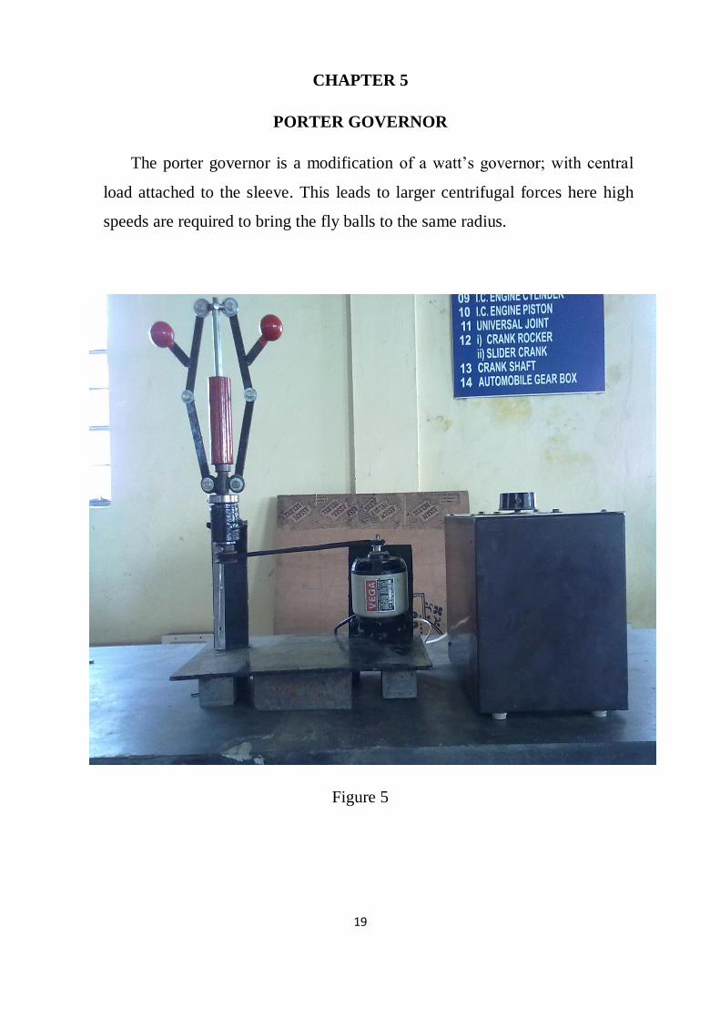
CHAPTER 5
PORTER GOVERNOR
The porter governor is a modification of a watt‟s governor; with central
load attached to the sleeve. This leads to larger centrifugal forces here high
speeds are required to bring the fly balls to the same radius.
Figure 5
Page 27
20
5.1 SPECIFICATIONS:
Basic Specifications:
(1) Power supply
(2) 230 V AC, Single phase, Variac.
Materials:
(1) Spindle: Stainless Steel
(2) Fly balls: Cast Iron
(3) Arms: Stainless steel
(4) Frame: Mild steel
(5) Dead weight: cast Iron
Governor Mechanism:
(1) Porter Governor
Page 28
21
5.2 PRINCIPLE:
The function of the governor is to regulate the mean speed of an engine,
when there are variations in the load .e.g. when the load on an engine increases,
its speed decreases therefore it becomes necessary to increases the supply of
working fluid .On the other hand, when the load on the engine decreases, its
speed increases and thus less working fluid is required. The governor
automatically controls the supply of the working fluid to the engine with the
varying load conditions and keeps the mean speed within certain limits.
A little consideration will show ,that when the load increases ,the
configuration of the governor changes and a valve is moved to increase the
supply of the working fluid ; conversely , when the load decreases , the engine
speed increases and the governor decreases the supply of working fluid.
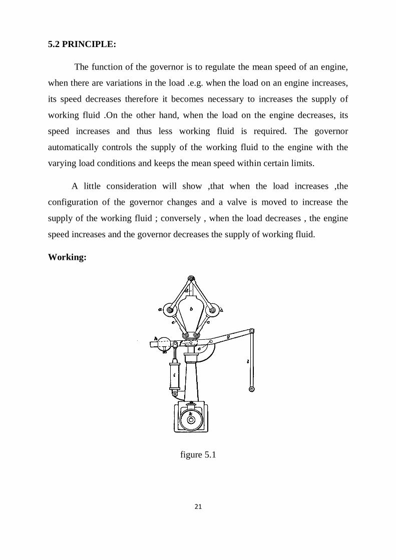
Working:
figure 5.1
Page 29
22
The porter governor was the first effective high speed engine governor,
designed by the American engineer George Porter. The governor is driven via a
pulley (k) through a set of bevel gears (not shown) a vertical shaft (d) is rotated,
this in turn drives from above the governor balls (a), through linkages (c) the
large and heavy governor deadweight (b) is also rotated, this is free to slide up
and down the shaft (d) but rotates at the same speed as the balls.
As rotational speed increases centrifugal force acts on the balls and they
try to fly outwards, they are restricted by the linkages (c) held by the weight of
the dead-weight (b), however, when a speed is reached at which this force
exceeds the resistance imposed by the dead-weight they will lift the weight up
and be allowed move outwards.
This action lifts the collar at the base of the dead-weight at point (f) this
lifts the lever (g) which is pivoted at point (e) the lever has a counterbalance
weight (a) and a dashpot or oil damper (I) which prevents rapid movements of
the governor mechanism which can lead to the engine 'hunting' which is
unwanted speed fluctuations due to the sensitivity of the governor.
Linkage (l) moves up or down and is connected to the engine this controls
the steam allowed into the cylinder either by the amount allowed through a
valve or the amount of time a valve is open for, if the engine runs too fast either
the quantity of steam allowed in will be reduced or it will be let in for a shorter
time, if the engine runs slower than either more steam is let in or it is let in for a
longer time.
Page 30
23
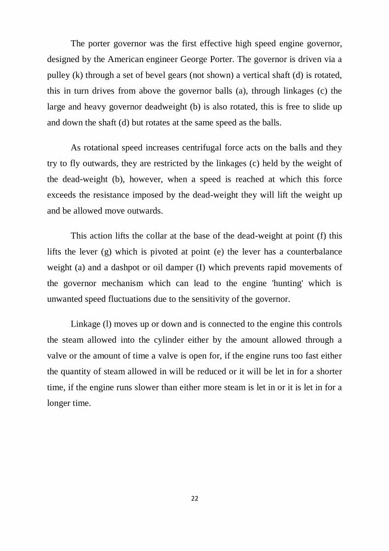
5.3 DESIGN PROCEDURE:
The design of porter governor involves determining the minimum and
maximum speed of the governor. The minimum speed occurs when the sleeve is
at its rest or initial position. The only difference between the watt and porter
governor is the inclusion of a dead weight as shown in the figure.
figure 5.3
Generally, Speed of rotation, N= (m+M)/m * 895/h
Where
m – Mass of the ball (kg)
Page 31
24
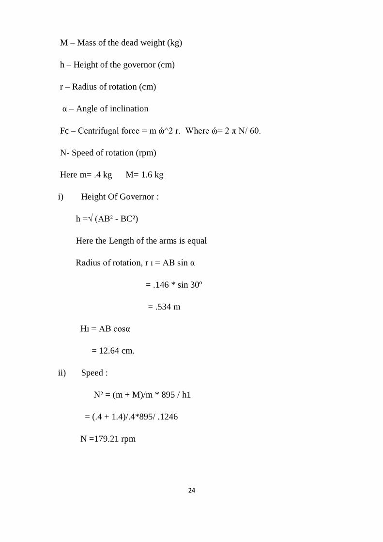
M – Mass of the dead weight (kg)
h – Height of the governor (cm)
r – Radius of rotation (cm)
α – Angle of inclination
Fc – Centrifugal force = m ώ^2 r. Where ώ= 2 π N/ 60.
N- Speed of rotation (rpm)
Here m= .4 kg M= 1.6 kg
i) Height Of Governor :
h =√ (AB² - BC²)
Here the Length of the arms is equal
Radius of rotation, r ı = AB sin α
= .146 * sin 30º
= .534 m
Hı = AB cosα
= 12.64 cm.
ii) Speed :
N² = (m + M)/m * 895 / h1
= (.4 + 1.4)/.4*895/ .1246
N =179.21 rpm
Page 32
25
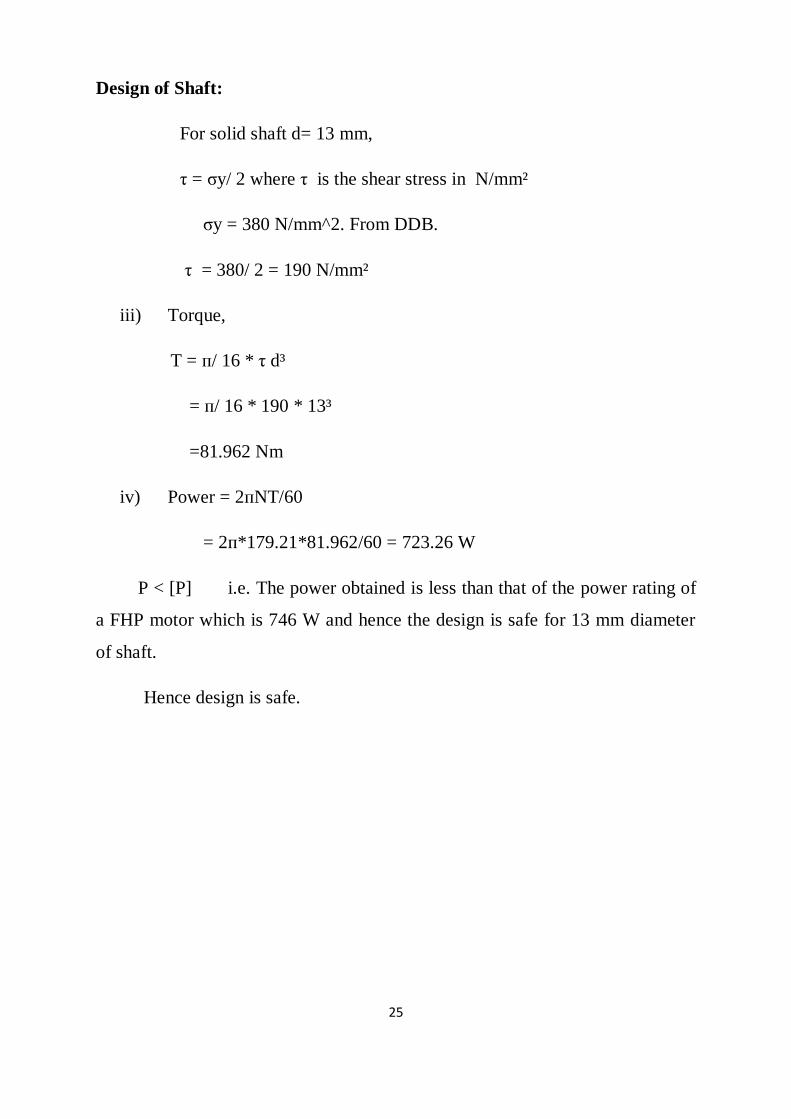
Design of Shaft:
For solid shaft d= 13 mm,
τ = σy/ 2 where τ is the shear stress in N/mm²
σy = 380 N/mm^2. From DDB.
τ = 380/ 2 = 190 N/mm²
iii) Torque,
T = п/ 16 * τ d³
= п/ 16 * 190 * 13³
=81.962 Nm
iv) Power = 2пNT/60
= 2п*179.21*81.962/60 = 723.26 W
P < [P] i.e. The power obtained is less than that of the power rating of
a FHP motor which is 746 W and hence the design is safe for 13 mm diameter
of shaft.
Hence design is safe.
Page 33
26
5.4 FABRICATION OF PORTER GOVERNOR
Fabrication as an industrial term refers to building metal structures by
cutting, bending and assembling.
The fabrication of porter governor involves:
i. Turning operation in lathe. (spindle)
ii. Threading operation in lathe.( Spindle)
iii. Drilling holes in porter arms, frame and dead weight.
iv. Step turning of sleeve.
v. Cylindrical grinding for good surface finish.
vi. Welding operation. (Frame and Arms).
vii. Gas cutting of frame.
The fabrication of the components is similar to that of the watt governor. As the
Dead weight is the only inclusion to watt governor setup.
Page 34
27
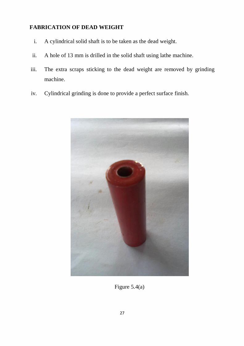
FABRICATION OF DEAD WEIGHT
i. A cylindrical solid shaft is to be taken as the dead weight.
ii. A hole of 13 mm is drilled in the solid shaft using lathe machine.
iii. The extra scraps sticking to the dead weight are removed by grinding
machine.
iv. Cylindrical grinding is done to provide a perfect surface finish.
Figure 5.4(a)
Page 35
28
CHAPTER 6
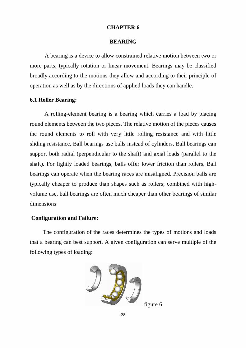
BEARING
A bearing is a device to allow constrained relative motion between two or
more parts, typically rotation or linear movement. Bearings may be classified
broadly according to the motions they allow and according to their principle of
operation as well as by the directions of applied loads they can handle.
6.1 Roller Bearing:
A rolling-element bearing is a bearing which carries a load by placing
round elements between the two pieces. The relative motion of the pieces causes
the round elements to roll with very little rolling resistance and with little
sliding resistance. Ball bearings use balls instead of cylinders. Ball bearings can
support both radial (perpendicular to the shaft) and axial loads (parallel to the
shaft). For lightly loaded bearings, balls offer lower friction than rollers. Ball
bearings can operate when the bearing races are misaligned. Precision balls are
typically cheaper to produce than shapes such as rollers; combined with high-
volume use, ball bearings are often much cheaper than other bearings of similar
dimensions
Configuration and Failure:
The configuration of the races determines the types of motions and loads
that a bearing can best support. A given configuration can serve multiple of the
following types of loading:
figure 6
Page 36
29
6.2 SPECIFICATIONS OF BEARING :
A Bearing is a machine element which is mounted on shafts for free and
smooth rotation. The bearing facilitates the rotation of the shaft along its axis
without any vibration. Generally for this purpose roller ball bearing is chosen
and we have done the same. The various stresses acting on a roller ball bearing
are
(i) Radial force acting on the bearing.
(ii) Axial thrust on the bearing
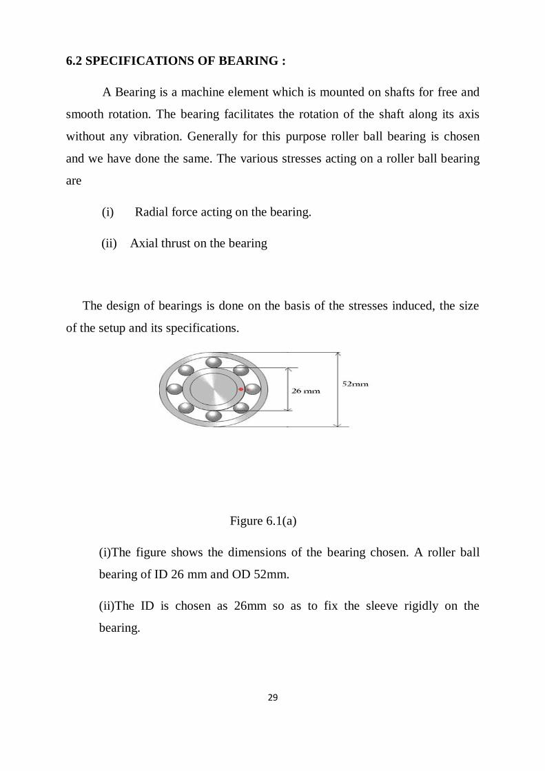
The design of bearings is done on the basis of the stresses induced, the size
of the setup and its specifications.
Figure 6.1(a)
(i)The figure shows the dimensions of the bearing chosen. A roller ball
bearing of ID 26 mm and OD 52mm.
(ii)The ID is chosen as 26mm so as to fix the sleeve rigidly on the
bearing.
Page 37
30
6.3 DESIGN PROCEDURE:
i) The design of bearings is done on the basis of the stresses induced and
the size of the setup.
ii) The radial force acting on the governor is given by
F = torque / distance. (N)
F = 81.951 / .30
Radial force F = 275 N
iii) For F = 275 N and the inner diameter d = 26 mm, The bearing to be
chosen is SKF 6006. SKF 6206 and SKF 6306. Out of which SKF
6206 is highly recommended and chosen by us.
Page 38
31
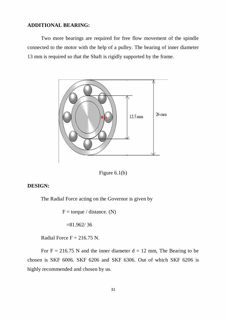
ADDITIONAL BEARING:
Two more bearings are required for free flow movement of the spindle
connected to the motor with the help of a pulley. The bearing of inner diameter
13 mm is required so that the Shaft is rigidly supported by the frame.
Figure 6.1(b)
DESIGN:
The Radial Force acting on the Governor is given by
F = torque / distance. (N)
=81.962/ 36
Radial Force F = 216.75 N.
For F = 216.75 N and the inner diameter d = 12 mm, The Bearing to be
chosen is SKF 6006. SKF 6206 and SKF 6306. Out of which SKF 6206 is
highly recommended and chosen by us.
Page 39
32
CHAPTER 7
MOTOR
7.1 SPECIFICATIONS:
Motor Specifications:
230 V, 0.32 Amps, Variable speed, Standard Make FHP Motor.
Control Panel
For speed control of motor.
7.2 WORKING:
A motor uses electrical energy to produce mechanical energy, usually
through the interaction of magnetic fields and current-carrying conductors. The
reverse process, producing electrical energy from mechanical energy, is
accomplished by a generator or dynamo. Electric motors can be run as
generators and vice versa, although this is not always practical. Electric motors
are ubiquitous, being found in applications as diverse as industrial fans, blowers
and pumps, machine tools, household appliances, power tools, and disk drives.
They may be powered by direct current or by alternating current from a central
electrical distribution grid. The smallest motors may be found in electric
wristwatches. Medium-size motors of highly standardized dimensions and
characteristics provide convenient mechanical power for industrial uses. The
very largest electric motors are used for propulsion of large ships, and for such
purposes as pipeline compressors, with ratings in the thousands of kilowatts.
Electric motors may be classified by the source of electric power, by their
internal construction, and by their application.
The physical principle of production of mechanical force by the
interactions of an electric current and a magnetic field was known as early as
Page 40
33
1821. Electric motors of increasing efficiency were constructed throughout the
19th century, but commercial exploitation of electric motors on a large scale
required efficient electrical generators and electrical distribution networks.
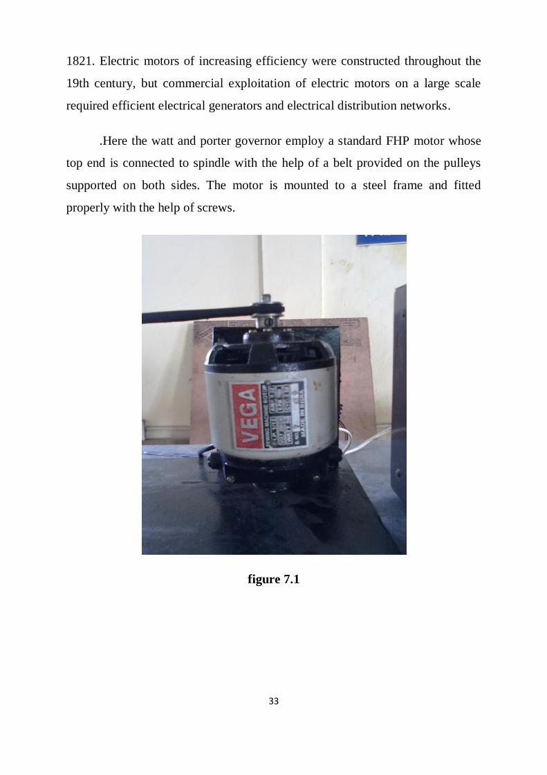
.Here the watt and porter governor employ a standard FHP motor whose
top end is connected to spindle with the help of a belt provided on the pulleys
supported on both sides. The motor is mounted to a steel frame and fitted
properly with the help of screws.
figure 7.1
Page 41
34
CHAPTER 8
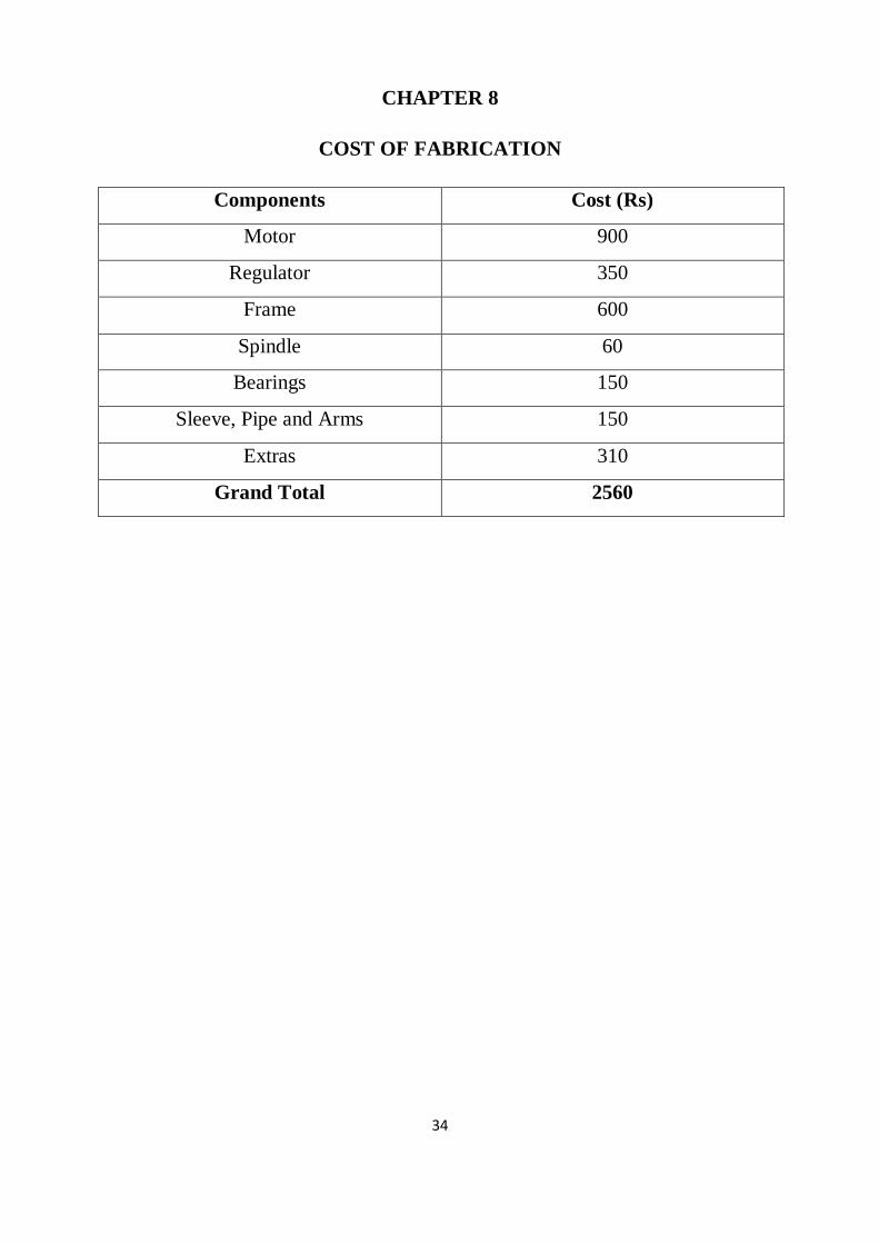
COST OF FABRICATION
Components Cost (Rs)
Motor 900
Regulator 350
Frame 600
Spindle 60
Bearings 150
Sleeve, Pipe and Arms 150
Extras 310
Grand Total 2560
Page 42
35
CHAPTER 9
APPLICATIONS
(i) On aircraft propellers the governor senses shaft rpm, and adjusts or
controls the angle of the blades to vary the torque load on the engine. Thus as
the aircraft speeds up (as in a dive) or slows (in climb) the RPM is held
constant.
(ii) Centrifugal flyweight mechanism driven by the engine is linked to the
throttle and works against a spring in a fashion similar to that of the
pneumatic governor, resulting in essentially identical operation. A centrifugal
governor is more complex to design and produce than a
(iii) Pneumatic governor. However, the centrifugal design is more
sensitive to speed changes and hence is better suited to engines that
experience large fluctuations in loading.
(iv) Electronic servo motor is linked to the throttle and controlled by an
electronic module that senses engine speed by counting electrical pulses
emitted by the ignition system or a magnetic pickup. The frequency of these
pulses varies directly with engine speed, allowing the control module to apply
a proportional voltage to the servo to regulate engine speed. Due to their
sensitivity and rapid response to speed changes, electronic governors are
often fitted to engine-driven generators designed to power computer
hardware, as the generator's output frequency must be held within narrow
limits to avoid malfunction.
Page 43
36
CHAPTER 10
HURDLES FACED
i) We experienced bending the spindle while trying to fix the bearing
in position which later led to wobbling of the spindle. Hence we
changed a new one later.
ii) Due to irregular speed control the arms bent while rotating which
we replaced later with a new arm of more harder material to
overcome that problem.
iii) We also experienced turbulence of the entire setup while operating
due to less weight of frame for which we added some extra weight
for stability.
iv) Fixing the bearing in position caused failure of bearings because of
hard impact by hammer for which we replaced the faulty bearing
later.
Page 44
37
CHAPTER 11
CONCLUSION
(i) Thus governor plays an important role in speed control.
(ii) It ensures regulation of speed at any conditions.
(ii) Obtaining the governor characteristics.
(iii) To study the effect of varying the mass of the center sleeve in
porter governor
SCOPE
(i) The governors extend their scope in all kind of vehicles. They can
be employed in hydro plants assessment.
(ii) They can also be used in speed sensing devices which employ
digital speed governors.
(iii) The introduction of analog and digital speed governors have created
a rage among the automobile industries.
Page 45
38
CHAPTER 12
REFERENCE
(i)Wheeler, Lynder Phelps (1947), "The Gibbs Governor for Steam
Engines", in Wheeler, Lynder Phelps; Waters, Everett Oyler;
(ii) Dudley, Samuel William, The Early Work of Willard Gibbs in
Applied Mechanics, New York: Henry Schuman, pp. 63–78
(iii)Wheeler, L. (1951). Josiah Willard Gibbs - the History of a Great
Mind. Woodbridge, CT: Ox Bow Press.
(iv)Harris, Tedric A. (2000, 4th edition). Rolling Bearing Analysis.
Wiley-Interscience. ISBN 0-471-35457-0.
(v)Machine Design (2007), Did You Know: Bud Wisecarver, Machine
Design, p. 1.