www.tjprc.org [email protected]
DESIGN AND FEM ANALYSIS OF TWO-WHEELER EXHAUST SYSTEM
VIVEK YADAV1 & PANKAJ KUMAR2
1Student, Department of Mechanical Engineering, Arya Institute of Engineering and Technology, Rajasthan, India
2Assistant Professor, Department of Mechanical Engineering, Arya Institute of Engineering and Technology, Rajasthan, India
ABSTRACT
The exhaust system has to perform many functions like creating pressure difference, controlling vibration and
controlling noise. The flue gases releases at very high temperature and high pressure pulses creates a high vibrations.
So, it is very necessary to control the vibrations and noise for the comfort of operator and to increase the life of engine.
There are various components inside the exhaust system are muffler, silencer, baffle assembly etc. The exhaust system
has suffered different types of loading like pressure load, acceleration load, fatigue loading and loading due to self-
weight. So in this journal paper, we study the behaviour of silencer and exhaust system on different loading. The
model is made on solid works with close dimensions, and analysis is done on Ansys workbench 15.0 software.
KEYWORDS:
Received: Apr 01, 2020; Accepted: Apr 21, 2020; Published: May 12, 2020; Paper Id.: IJAuERDJUN20203
1. INTRODUCTION
The function of silencer is to reduce noise, vibration and pollution. This can be done by two ways one is catalytic
convertor and other is silencer. For the working of catalytic convertor the temperature must be approx. 900 oC and
this temperature cannot be reached in two wheeler so catalytic convertor cannot be used in two wheeler exhaust
system. The other is silencer, which works on the reflection phenomena, it transmits the sound waves towards the
end of chamber and chamber reflects back towards the source, these reflect each other and cancel each other. It helps
in the reduction of sound.
There is opening and closing of the exhaust valve with each cycle of combustion and the pressure varies
from high to low or from low to high, hence silencer has to bear all the vibration. The vibrations vary with the load
and the speed, at high load and speed the vibrations are high and thermal stresses are high.
The silencer has thermal stresses so to increase the life of silencer the thermal stress need to be focused and
uniform distribution of thermal stresses must be there. The length of the exhaust pipe also affects the efficiency of
the engine. If the exhaust gases have to travel a large distance the efficiency decreases as in sports bike it is easily
seen that the exhaust pipe is small in length. The Objectives of this paper are
-Cad modelling of existing silencer.
-Cad modelling of internal parts of silencer.
-Analysis of internal parts of silencer.
-Analysis of full exhaust system.
2. Analysis of Silencer
Orig
ina
l Article
International Journal of Automobile Engineering
Research and Development (IJAuERD)
ISSN (P): 2277–4785; ISSN (E): 2278–9413
Vol. 10, Issue 1, Jun 2020, 19–34
© TJPRC Pvt. Ltd.
20 Vivek Yadav & Pankaj Kumar
Impact Factor (JCC): 7.6093 NAAS Rating: 3.05
Silencer is mainly pressure reducing instrument, but back pressure effects a lot generally more the back pressure less is the
efficiency, back press is the pressure which restricts the flow of exhaust gases from combustion chamber mainly better the
muffler in restricting sound more back pressure is created. So, there should be optimization between the two noises and back
pressure.
Size
The available space has also an influence on the size and the type of muffler that may be used. A muffler is mainly designed
for optimum attenuation however if it takes large space then, it is useless. Largermuffler is high in weight, and leads to high
manufacturing cost. For a high performance vehicle it affects performance/acceleration, etc. Therefore, a small light weight
muffler is desirable.
Transmission Loss
Transmission loss is the characteristic parameter, which shows the performance of muffler. Transmission loss is varying with
respect to change in geometry parameters such as diameter of pipe, number of holes, and number of pipes.
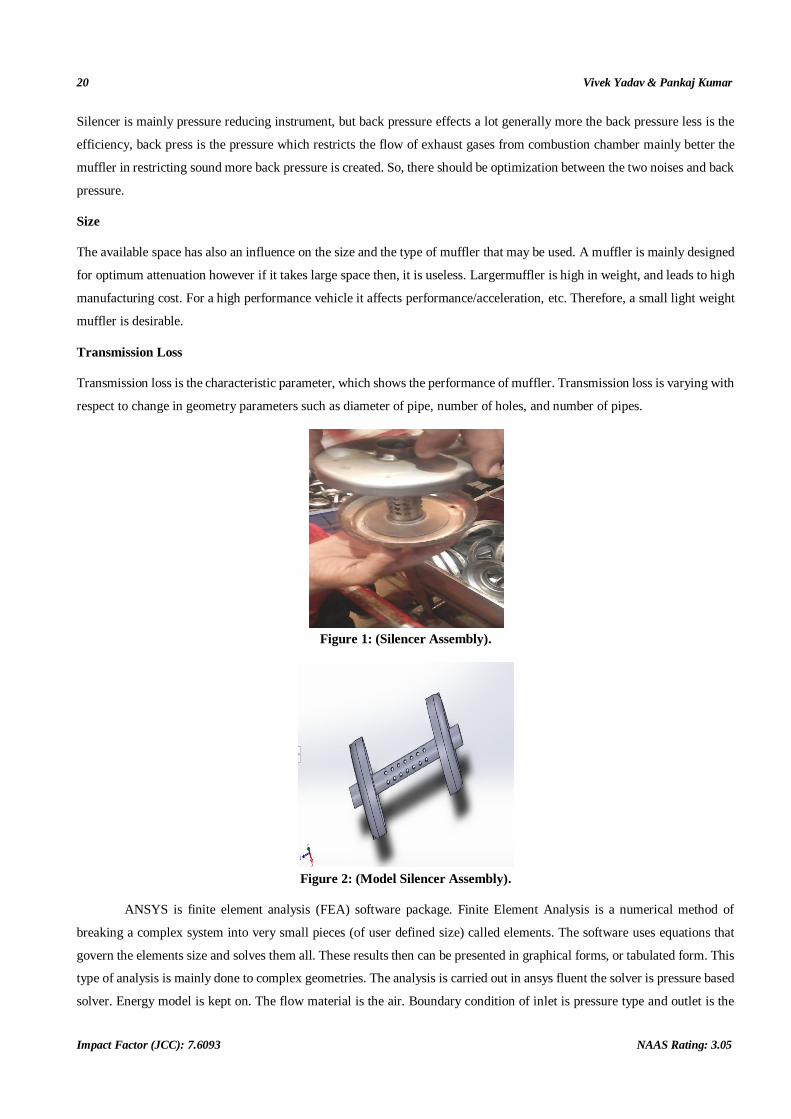
Figure 1: (Silencer Assembly).
Figure 2: (Model Silencer Assembly).
ANSYS is finite element analysis (FEA) software package. Finite Element Analysis is a numerical method of
breaking a complex system into very small pieces (of user defined size) called elements. The software uses equations that
govern the elements size and solves them all. These results then can be presented in graphical forms, or tabulated form. This
type of analysis is mainly done to complex geometries. The analysis is carried out in ansys fluent the solver is pressure based
solver. Energy model is kept on. The flow material is the air. Boundary condition of inlet is pressure type and outlet is the
Design and FEM Analysis of Two-Wheeler Exhaust System 21
www.tjprc.org [email protected]
pressure outlet type. The proper initialization is fixed and the calculation is made to run. The following results are obtained
as below.
Figure 3: Meshing Pattern.
Figure 4: Meshing.
22 Vivek Yadav & Pankaj Kumar
Impact Factor (JCC): 7.6093 NAAS Rating: 3.05
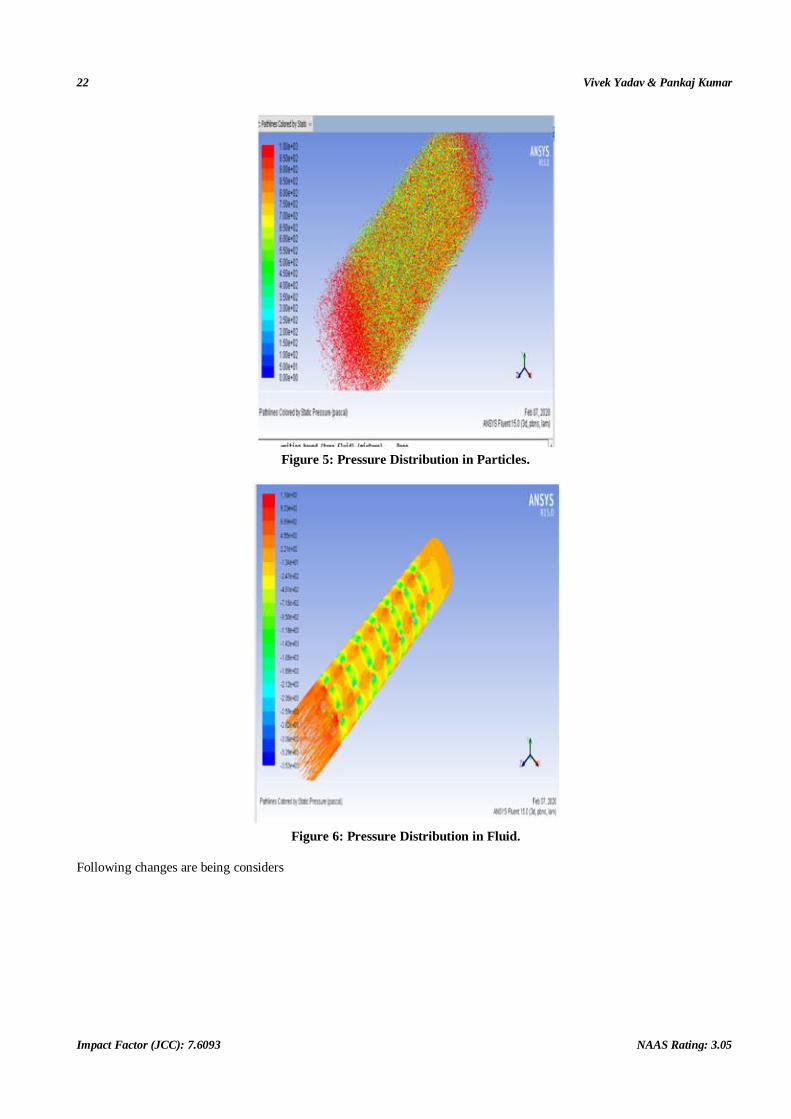
Figure 5: Pressure Distribution in Particles.
Figure 6: Pressure Distribution in Fluid.
Following changes are being considers
Design and FEM Analysis of Two-Wheeler Exhaust System 23
www.tjprc.org [email protected]
Figure 7: Velocity Distribution in Silencer.
Figure 8: Velocity Distribution Near Holes.
24 Vivek Yadav & Pankaj Kumar
Impact Factor (JCC): 7.6093 NAAS Rating: 3.05
Figure 9: Strain Rate in Silencer.
3. Analysis of Full Exhaust System
Figure 10: Shear Stress in Silencer.
Design and FEM Analysis of Two-Wheeler Exhaust System 25
www.tjprc.org [email protected]
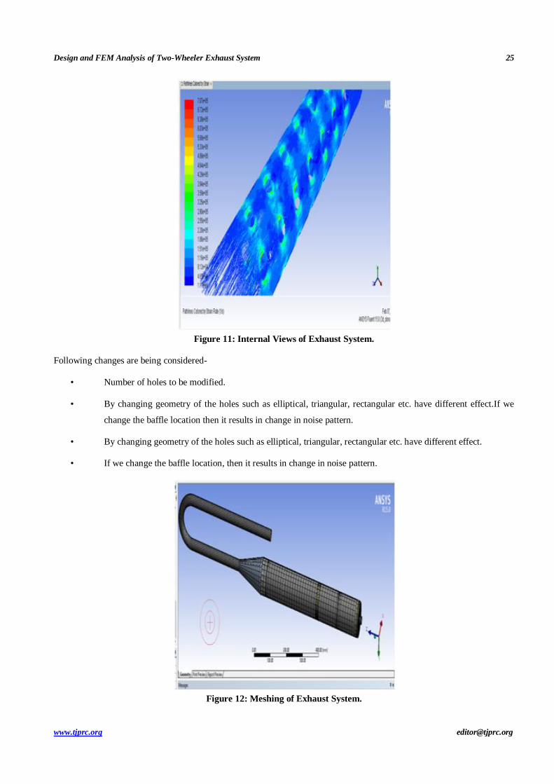
Figure 11: Internal Views of Exhaust System.
Following changes are being considered-
• Number of holes to be modified.
• By changing geometry of the holes such as elliptical, triangular, rectangular etc. have different effect.If we
change the baffle location then it results in change in noise pattern.
• By changing geometry of the holes such as elliptical, triangular, rectangular etc. have different effect.
• If we change the baffle location, then it results in change in noise pattern.
Figure 12: Meshing of Exhaust System.
26 Vivek Yadav & Pankaj Kumar
Impact Factor (JCC): 7.6093 NAAS Rating: 3.05
Figure 13: Meshing Internal Parts View.
Table 1
Model Meshing Details
Use Advanced Size Function On: Curvature
Relevance Center Coarse
Initial Size Seed Active Assembly
Smoothing Medium
Transition Fast
Span Angle Center Coarse
Curvature Normal Angle Default (30.0 °)
Min Size Default (1.39070 mm)
Max Face Size Default (6.95370 mm)
Max Size Default (6.95370 mm)
Growth Rate Default
Minimum Edge Length 0.561720 mm
Use Automatic Inflation None
Nodes 95710
Elements 29812
Mesh Metric None
Structural Steel
Table 2
Density 7.85e-006 kg mm^-3
Coefficient of Thermal Expansion 1.2e-005 C^-1
Specific Heat 4.34e+005 mJ kg^-1 C^-1
Thermal Conductivity 6.05e-002 W mm^-1 C^-1
Resistivity 1.7e-004 ohm mm
Design and FEM Analysis of Two-Wheeler Exhaust System 27
www.tjprc.org [email protected]
Structural Steel > Alternating Stress Mean Stress
Table 3
Alternating Stress
MPa Cycles
Mean Stress
MPa
3999 10 0
2827 20 0
1896 50 0
1413 100 0
1069 200 0
441 2000 0
262 10000 0
214 20000 0
138 1.e+005 0
114 2.e+005 0
86.2 1.e+006 0
Structural Steel > Strain-Life Parameters
Table 4
Strength
Coefficient
MPa
Strength
Exponent
Ductility
Coefficient
Ductility
Exponent
Cyclic Strength
Coefficient MPa
Cyclic Strain
Hardening Exponent
920 -0.106 0.213 -0.47 1000 0.2
Structural Steel > Isotropic Elasticity
Table 5
Temperature C Young's Modulus MPa Poisson's Ratio Bulk Modulus MPa Shear Modulus MPa 2.e+005 0.3 1.6667e+005 76923
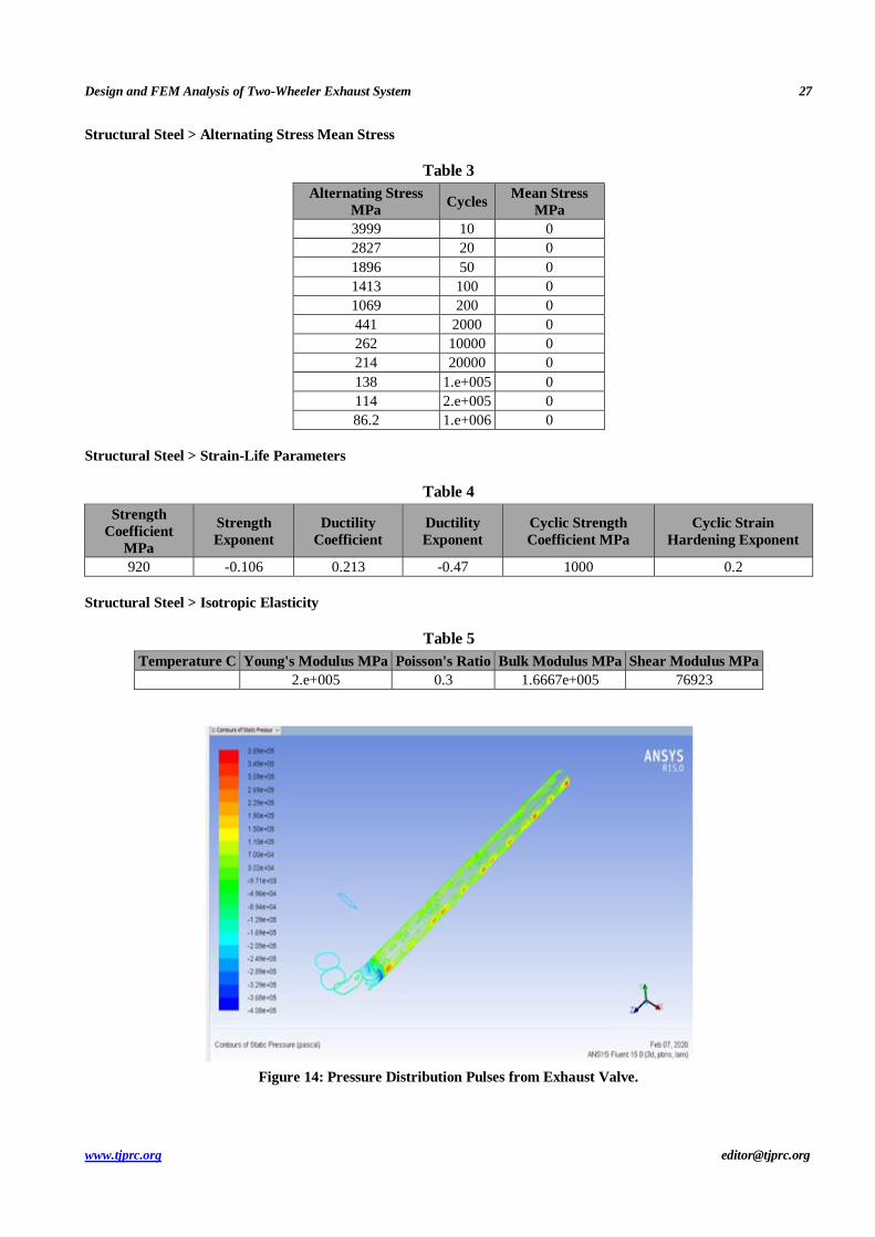
Figure 14: Pressure Distribution Pulses from Exhaust Valve.
28 Vivek Yadav & Pankaj Kumar
Impact Factor (JCC): 7.6093 NAAS Rating: 3.05
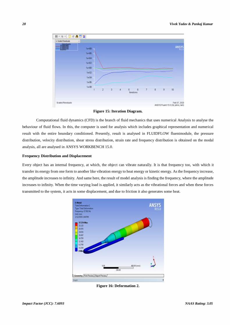
Figure 15: Iteration Diagram.
Computational fluid dynamics (CFD) is the branch of fluid mechanics that uses numerical Analysis to analyse the
behaviour of fluid flows. In this, the computer is used for analysis which includes graphical representation and numerical
result with the entire boundary conditioned. Presently, result is analysed in FLUIDFLOW fluentmodule, the pressure
distribution, velocity distribution, shear stress distribution, strain rate and frequency distribution is obtained on the modal
analysis, all are analysed in ANSYS WORKBENCH 15.0.
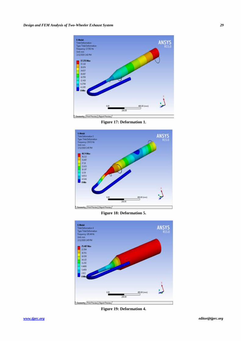
Frequency Distribution and Displacement
Every object has an internal frequency, at which, the object can vibrate naturally. It is that frequency too, with which it
transfer its energy from one form to another like vibration energy to heat energy or kinetic energy. As the frequency increase,
the amplitude increases to infinity. And same here, the result of model analysis is finding the frequency, where the amplitude
increases to infinity. When the time varying load is applied, it similarly acts as the vibrational forces and when these forces
transmitted to the system, it acts in some displacement, and due to friction it also generates some heat.
Figure 16: Deformation 2.
Design and FEM Analysis of Two-Wheeler Exhaust System 29
www.tjprc.org [email protected]
Figure 17: Deformation 1.
Figure 18: Deformation 5.
Figure 19: Deformation 4.
30 Vivek Yadav & Pankaj Kumar
Impact Factor (JCC): 7.6093 NAAS Rating: 3.05
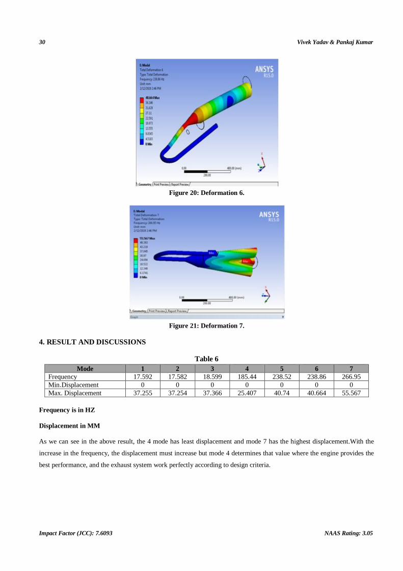
Figure 20: Deformation 6.
Figure 21: Deformation 7.
4. RESULT AND DISCUSSIONS
Table 6
Mode 1 2 3 4 5 6 7
Frequency 17.592 17.582 18.599 185.44 238.52 238.86 266.95
Min.Displacement 0 0 0 0 0 0 0
Max. Displacement 37.255 37.254 37.366 25.407 40.74 40.664 55.567
Frequency is in HZ
Displacement in MM
As we can see in the above result, the 4 mode has least displacement and mode 7 has the highest displacement.With the
increase in the frequency, the displacement must increase but mode 4 determines that value where the engine provides the
best performance, and the exhaust system work perfectly according to design criteria.
Design and FEM Analysis of Two-Wheeler Exhaust System 31
www.tjprc.org [email protected]
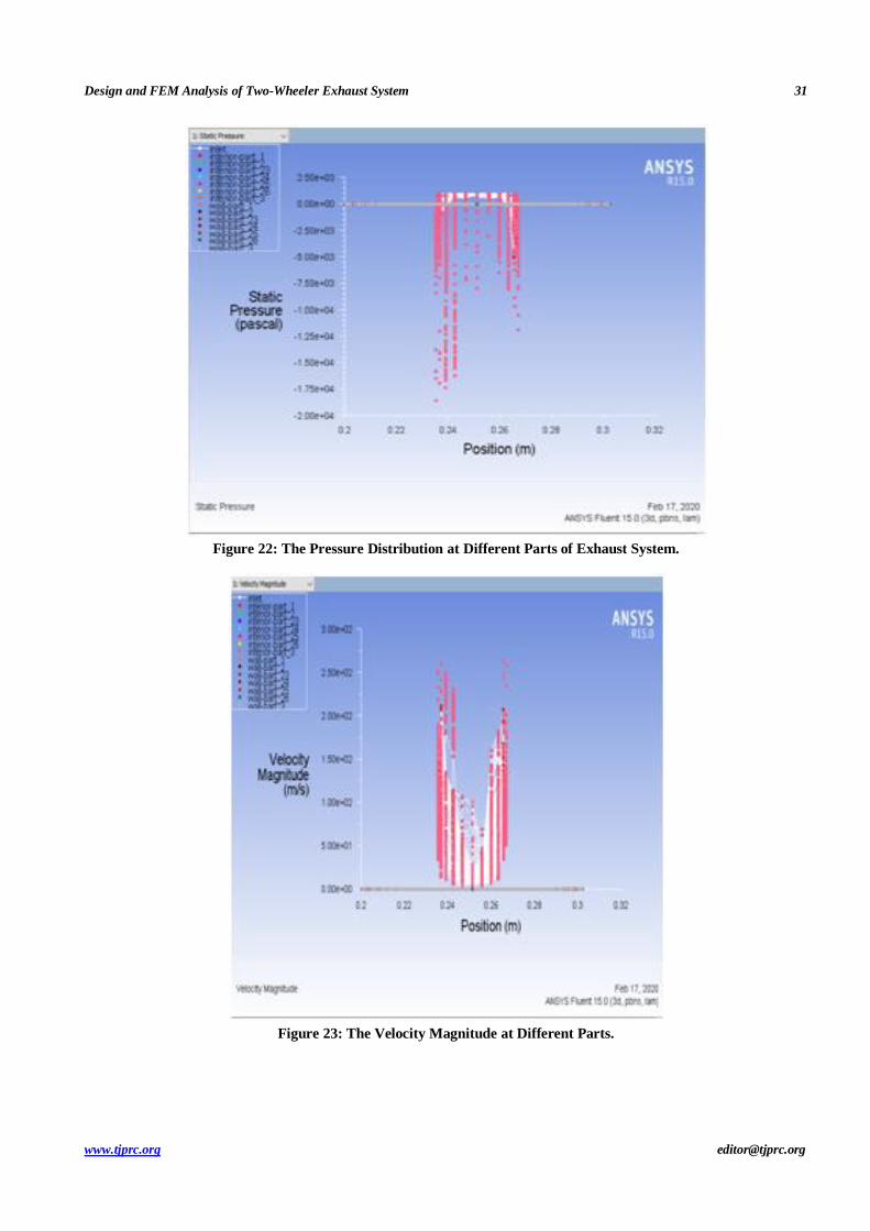
Figure 22: The Pressure Distribution at Different Parts of Exhaust System.
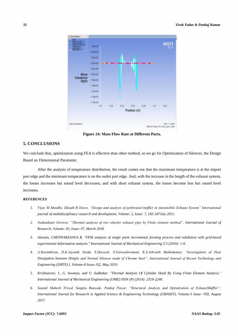
Figure 23: The Velocity Magnitude at Different Parts.
32 Vivek Yadav & Pankaj Kumar
Impact Factor (JCC): 7.6093 NAAS Rating: 3.05
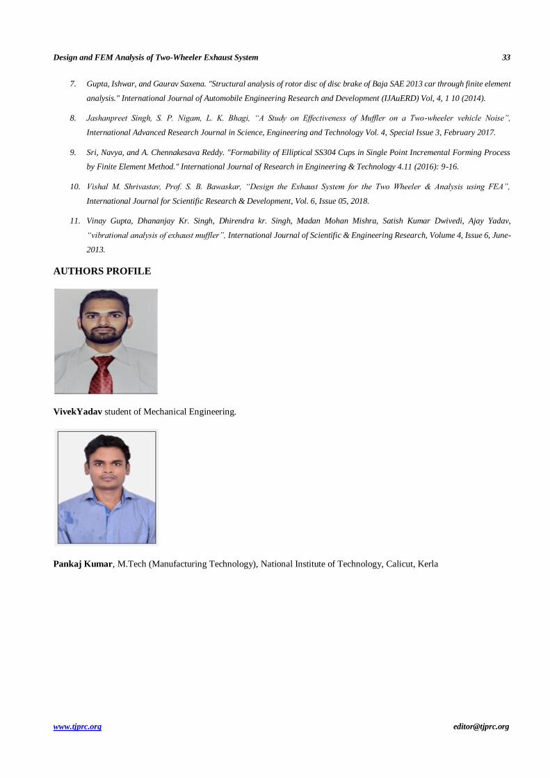
Figure 24: Mass Flow Rate at Different Parts.
5. CONCLUSIONS
We conclude that, optimization using FEA is effective than other method, so we go for Optimization of Silencer, the Design
Based on Dimensional Parameter.
After the analysis of temperature distribution, the result comes out that the maximum temperature is at the import
port edge and the minimum temperature is on the outlet port edge. And, with the increase in the length of the exhaust system,
the losses increases but sound level decreases; and with short exhaust system, the losses become less but sound level
increases.
REFERENCES
1. Vijay M Mundhe, Eknath R Deore, “Design and analysis of perforated muffler in Automobile Exhaust System” International
journal of multidisciplinary research and development, Volume: 2, Issue: 7, 182-187July 2015.
2. Naikankatte Gowrav, “Thermal analysis of two wheeler exhaust pipe by Finite element method”, International Journal of
Research, Volume: 05, Issue: 07, March 2018.
3. Alavala, CHENNAKESAVA R. "FEM analysis of single point incremental forming process and validation with grid-based
experimental deformation analysis." International Journal of Mechanical Engineering 5.5 (2016): 1-6.
4. A.Ravinthiran, D.K.Jayanth Naidu, S.Hareesh, N.Gurusubramani, K.S.Athvaith Muthukumar, “Investigation of Heat
Dissipation between Dimple and Normal Silencer made of Chrome Steel”, International Journal of Recent Technology and
Engineering (IJRTE) I, Volume-8 Issue-1S2, May 2019.
5. Krishnaveni, J., G. Sowmya, and U. Sudhakar. "Thermal Analysis Of Cylinder Head By Using Finite Element Analysis."
International Journal of Mechanical Engineering (IJME) ISSN (P) (2014): 2319-2240.
6. Saumil Mahesh Trived, Sangita Bansode, Pankaj Pawar, “Structural Analysis and Optimization of ExhaustMuffler”,
International Journal for Research in Applied Science & Engineering Technology (IJRASET), Volume-5 Issue- VIII, August
2017.
Design and FEM Analysis of Two-Wheeler Exhaust System 33
www.tjprc.org [email protected]
7. Gupta, Ishwar, and Gaurav Saxena. "Structural analysis of rotor disc of disc brake of Baja SAE 2013 car through finite element
analysis." International Journal of Automobile Engineering Research and Development (IJAuERD) Vol, 4, 1 10 (2014).
8. Jashanpreet Singh, S. P. Nigam, L. K. Bhagi, “A Study on Effectiveness of Muffler on a Two-wheeler vehicle Noise”,
International Advanced Research Journal in Science, Engineering and Technology Vol. 4, Special Issue 3, February 2017.
9. Sri, Navya, and A. Chennakesava Reddy. "Formability of Elliptical SS304 Cups in Single Point Incremental Forming Process
by Finite Element Method." International Journal of Research in Engineering & Technology 4.11 (2016): 9-16.
10. Vishal M. Shrivastav, Prof. S. B. Bawaskar, “Design the Exhaust System for the Two Wheeler & Analysis using FEA”,
International Journal for Scientific Research & Development, Vol. 6, Issue 05, 2018.
11. Vinay Gupta, Dhananjay Kr. Singh, Dhirendra kr. Singh, Madan Mohan Mishra, Satish Kumar Dwivedi, Ajay Yadav,
“vibrational analysis of exhaust muffler”, International Journal of Scientific & Engineering Research, Volume 4, Issue 6, June-
2013.
AUTHORS PROFILE
VivekYadav student of Mechanical Engineering.
Pankaj Kumar, M.Tech (Manufacturing Technology), National Institute of Technology, Calicut, Kerla