DESIGN AND IMPLEMENTATION FOR A MULTI- STANDARD TURBO DECODER USING A RECONFIGURABLE ASIP By Eid Mohamed Abdel-Hamid Abdel-Azim A Thesis Submitted to the Faculty of Engineering at Cairo University in Partial Fulfillment of the Requirements for the Degree of MASTER OF SCIENCE in ELECTRONICS AND ELECTRICAL COMMUNICATIONS ENGINEERING FACULTY OF ENGINEERING, CAIRO UNIVERSITY GIZA, EGYPT 2013
This thesis presents an efficient architecture to implement a turbo decoder using a
scalable low energy application specific instruction-set processor (ASIP). The
parallelism on the ASIP architecture is proposed to achieve the high-throughput
demand for turbo decoder which is one of the most important requirements of the
Fourth Generation (4G) wireless communication systems. We show the effects on the
throughput, the area, and the hardware utilizations of the different turbo decoder
schemes.
AcknowledgmentsI would like to thank my supervisors, Dr. Ahmed F. Shalash and Dr. Hossam A. H.
Fahmy, for their continuous support, advice, and guidance throughout my work.Special thanks to my dear mother, my dear father for their continuous support and
encouragement during all working days.I also wish to express my appreciation to my colleagues at the Center of Wireless
Studies (CWS).
i
DedicationTo my mother, my father, my brothers and my sister.
5.1 An example for no collisions for WiMAX interleaver when M=1 . . . . . 375.2 An example for collisions happen for WiMAX interleaver when M=0.96 . 385.3 Maximum buffer sizes for 3GPP2 CDMA2K interleaver for different
window sizes with 8 parallel windows . . . . . . . . . . . . . . . . . . . 395.4 Maximum buffer sizes for LTE interleaver for different window sizes
with 8 parallel windows . . . . . . . . . . . . . . . . . . . . . . . . . . 395.5 Maximum latency for 3GPP2 CDMA2K interleaver for different window
sizes with 8 parallel windows . . . . . . . . . . . . . . . . . . . . . . . 405.6 Parallel architecture with adding delayed buffers to reduce the number of
concurrent values need to write by half at every clock . . . . . . . . . . . 405.7 The data alignment block receives LLR values and stores them until pro-
cessed by the targeted memory bank . . . . . . . . . . . . . . . . . . . . 415.8 The controller of the data alignment block with divided into p small con-
trollers . . . . . . . . . . . . . . . . . . . . . . . . . . . . . . . . . . . . 425.9 The controller of the data alignment block with divided into p small con-
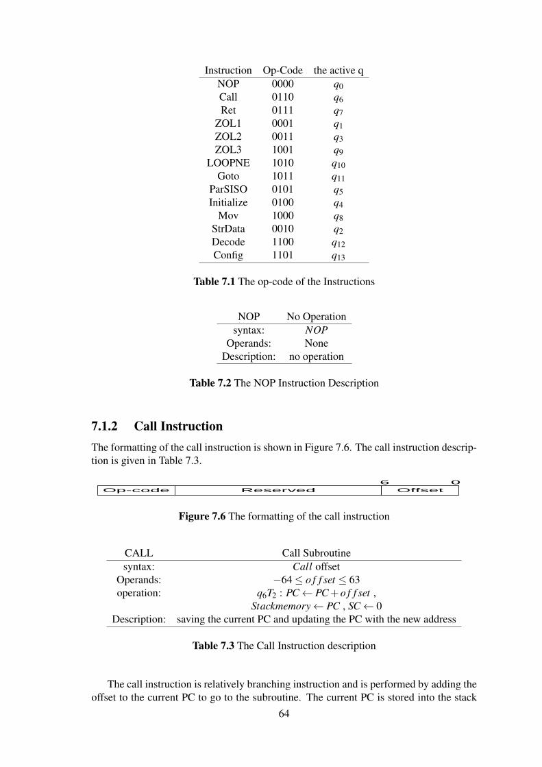
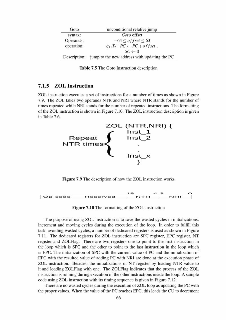
7.1 General block diagram architecture for the processor . . . . . . . . . . . 617.2 State diagram of non-pipelined processor . . . . . . . . . . . . . . . . . 627.3 Block Diagram for generating the Tn and qn signals . . . . . . . . . . . . 627.4 The process of the execution of the pipelined instructions . . . . . . . . . 637.5 The formatting of the Return instruction . . . . . . . . . . . . . . . . . . 637.6 The formatting of the call instruction . . . . . . . . . . . . . . . . . . . . 647.7 The formatting of the Return instruction . . . . . . . . . . . . . . . . . . 657.8 The formatting of the Goto instruction . . . . . . . . . . . . . . . . . . . 657.9 The description of how the ZOL instruction works . . . . . . . . . . . . . 667.10 The formatting of the ZOL instruction . . . . . . . . . . . . . . . . . . . 667.11 The block diagram of the ZOL instruction control parts including dedi-
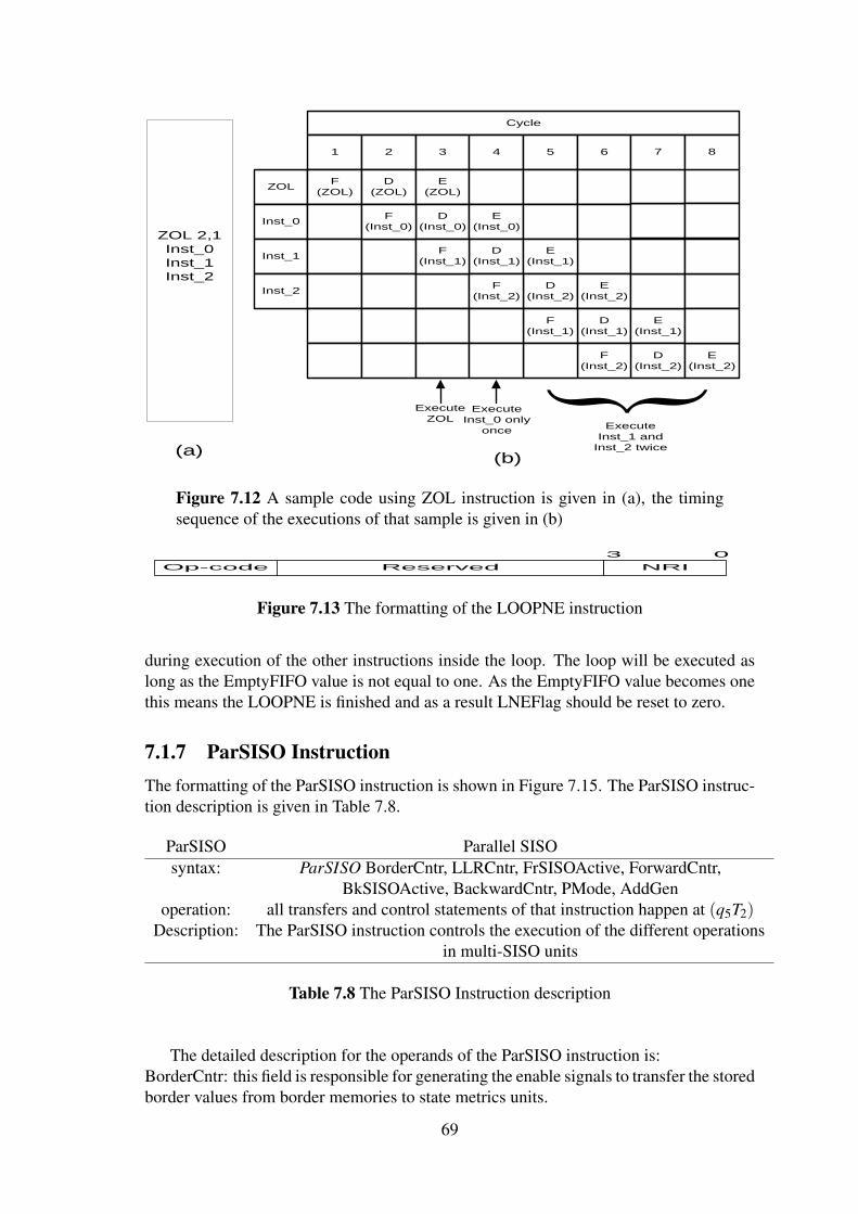
cated registers in details . . . . . . . . . . . . . . . . . . . . . . . . . . . 677.12 A sample code using ZOL instruction is given in (a), the timing sequence
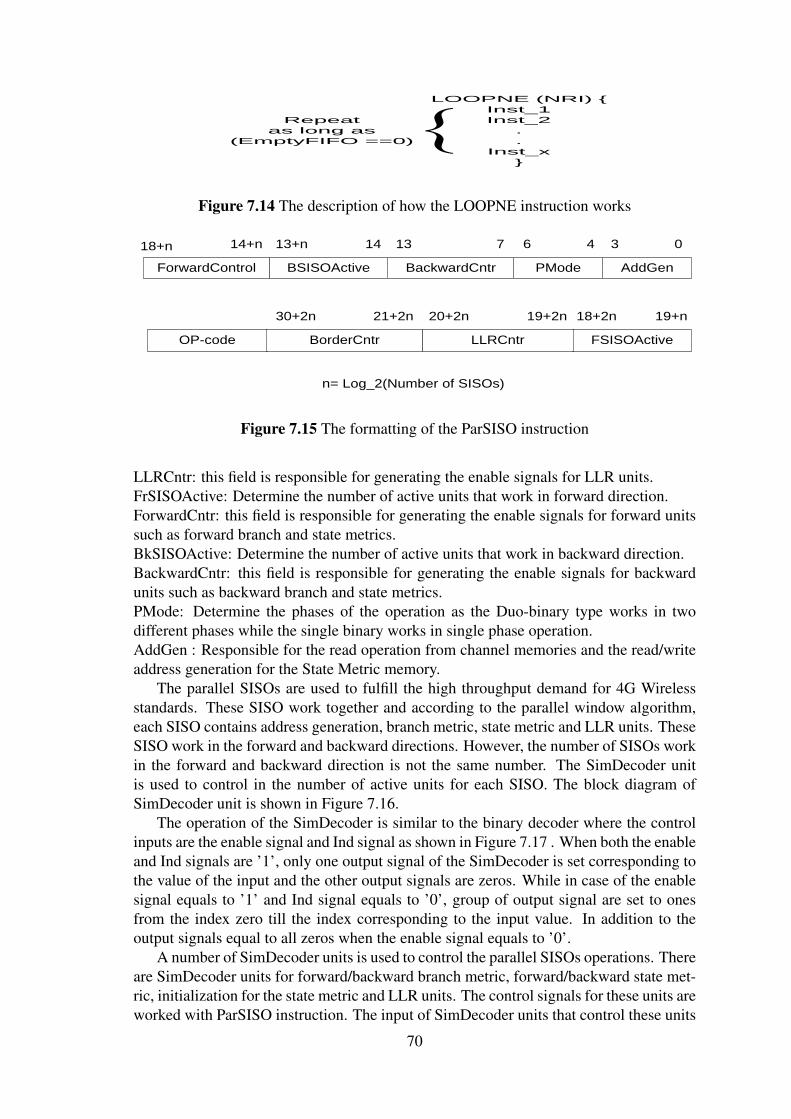
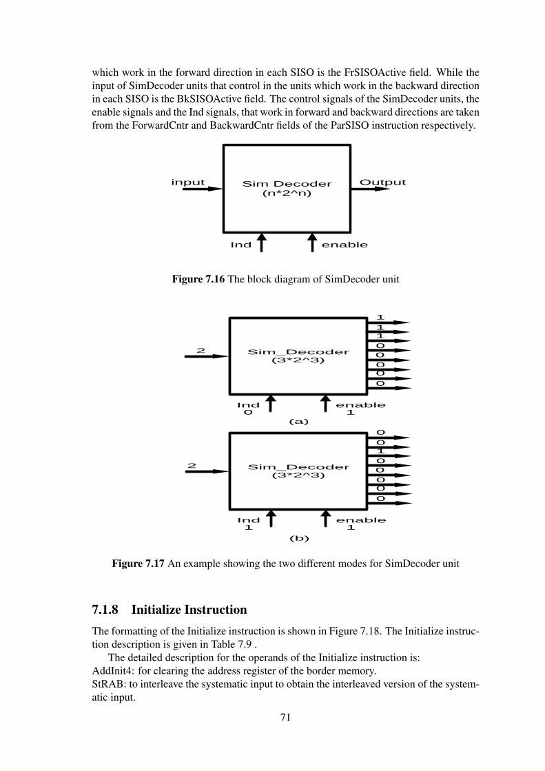
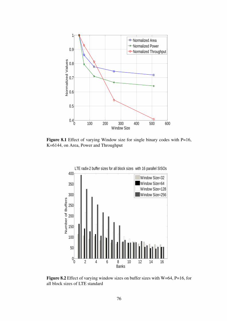
of the executions of that sample is given in (b) . . . . . . . . . . . . . . . 697.13 The formatting of the LOOPNE instruction . . . . . . . . . . . . . . . . 697.14 The description of how the LOOPNE instruction works . . . . . . . . . . 707.15 The formatting of the ParSISO instruction . . . . . . . . . . . . . . . . . 707.16 The block diagram of SimDecoder unit . . . . . . . . . . . . . . . . . . 717.17 An example showing the two different modes for SimDecoder unit . . . . 717.18 The formatting of the Initialize instruction . . . . . . . . . . . . . . . . . 727.19 The formatting of the Move instruction . . . . . . . . . . . . . . . . . . . 727.20 The formatting of the StrData instruction . . . . . . . . . . . . . . . . . . 737.21 The formatting of the Decode instruction . . . . . . . . . . . . . . . . . . 747.22 The formatting of the Config instruction . . . . . . . . . . . . . . . . . . 74
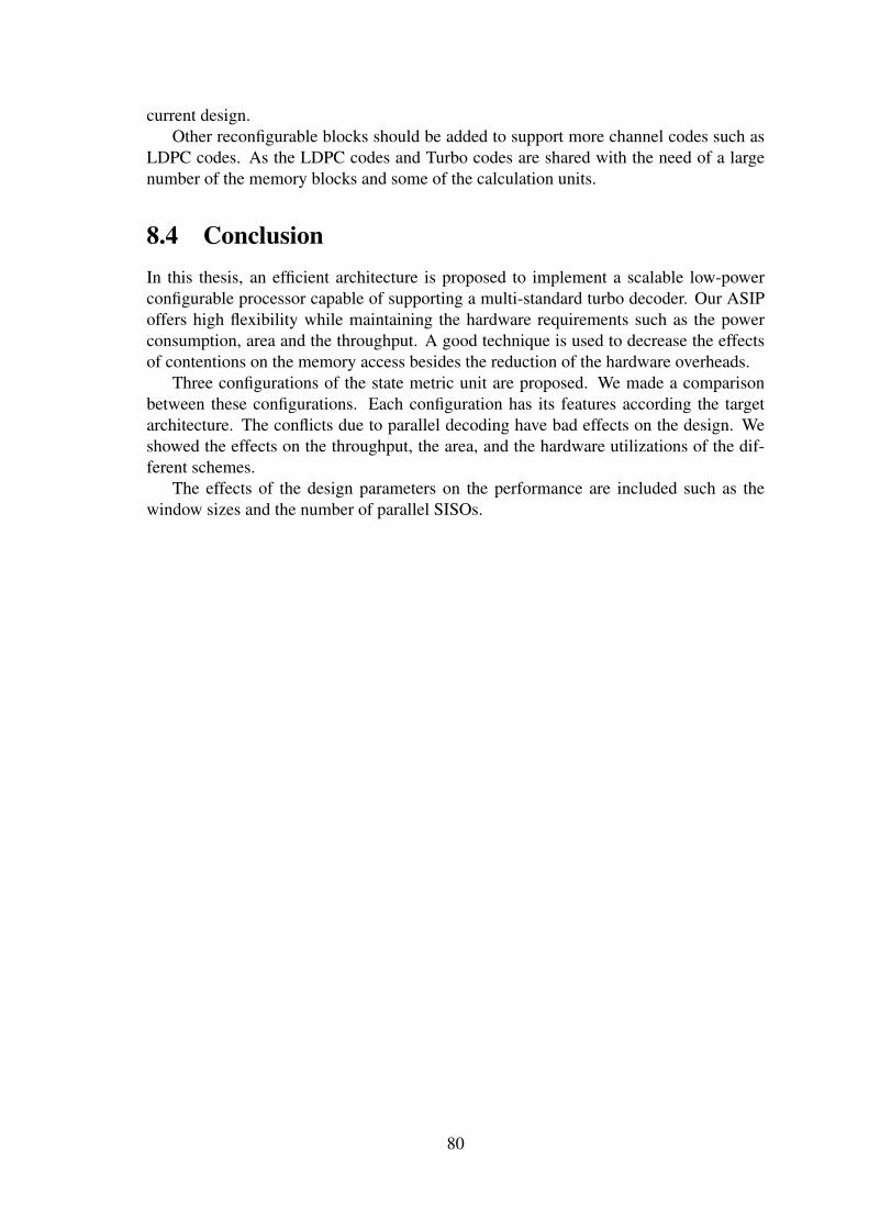
8.1 Effect of varying Window size for single binary codes with P=16, K=6144,on Area, Power and Throughput . . . . . . . . . . . . . . . . . . . . . . 76
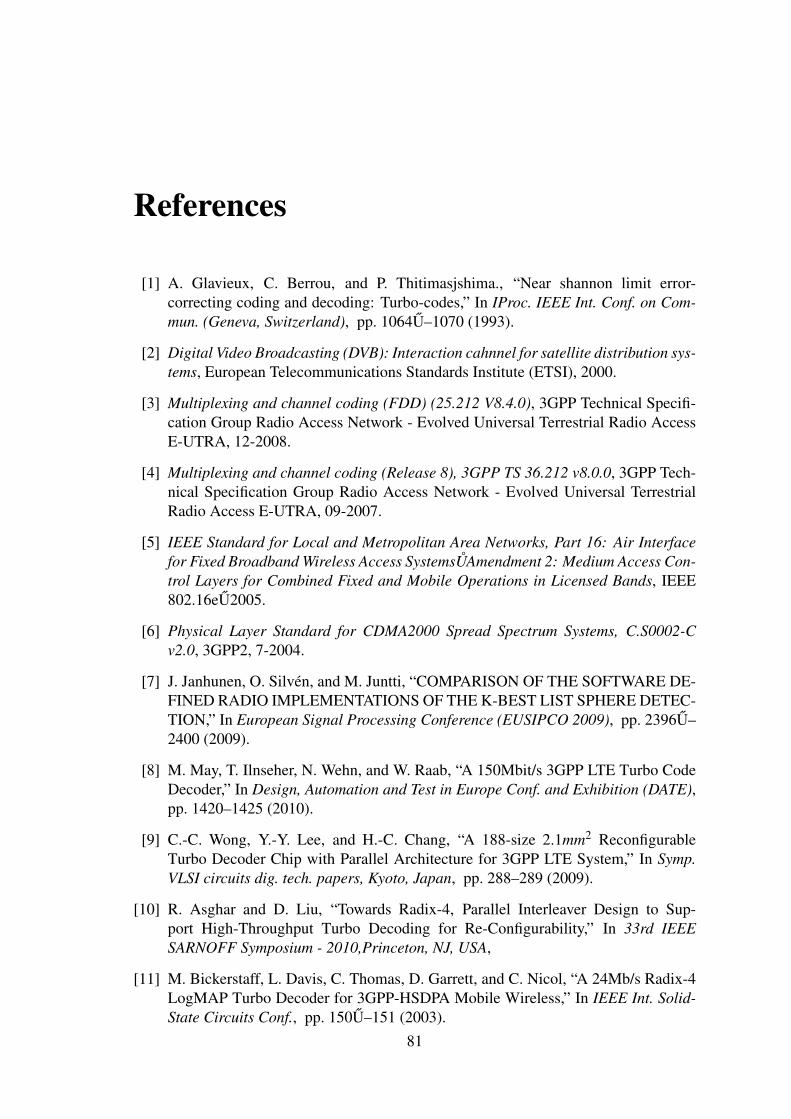
8.2 Effect of varying window sizes on buffer sizes with W=64, P=16, for allblock sizes of LTE standard . . . . . . . . . . . . . . . . . . . . . . . . . 76
8.3 Effect of varying number of parallel SISOs on the latency between thetwo decoders due to memory conflicts with W=64 and for all block sizesof 3GPP2 CDMA2000 standard . . . . . . . . . . . . . . . . . . . . . . 77
ix
List of Symbols
N : The code block size in pair of bitsK : The code block size in bitsA : First systematic output sub-block of the CTC interleaverB : Second systematic output sub-block of the CTC interleaverY : First Parity output sub-block of the CTC interleaverW : Second Parity output sub-block of the CTC interleaverY 2 : Third Parity output sub-block of the CTC interleaverW2 : Fourth Parity output sub-block of the CTC interleaverSc : Circular stateNSCH : The number of available sub channelsNCPC : The modulation orderR : The coding ratec :The input to the Turbo code internal interleaverc′ : The output from the Turbo code internal interleaverz : First Parity output of the LTE interleaverz′ : Second Parity output of the LTE interleaverlnP(uk|y) : a-posteriori-probabilityPext(uk|y) :The extrinsic LLR in log domainy = {A,B,Y,W} :The noisy soft input valuesW : Window sizeWG : Guard window sizek : The time instantsk : The current state at time instant kαk(s) : The forward state metric at time instant kβk(s) : The backward state metric at time instant kγk : the branch state metricTk : The branch LLRs at time instant kΛext : The extrinsic LLR of received dataP : Number of the parallel SISOsRb : the decoding throughputi : Iterations numberfclk : the operating frequencyq : The bit-width of the fractional partint : The bit-width of integer part
x
List of Abbreviations
RSC : Recursive Systematic ConvolutionalCRSC : Circular Recursive Systematic ConvolutionalCTC : Convolutional Turbo CodesSISO : Soft In Soft OutMAP : Maximum Aposterior ProbabilityLLR : Log Likely-hood RatioBER : Bit error rateFER : Frame error rateNII : The next iteration initializationRPDP : Relative power delay productZOL : Zero overhead loopFPGA : Field Programmable Gate ArrayLDPC : Low Density Parity checkQAM : Quadrature Amplitude ModulationQPSK : Quadrature Phase shift keyingWiMAX : Worldwide Interoperability for Microwave accessLT E : Long Term EvolutionHSPA : High Speed Packet Access3GPP : 3rd Generation Partnership ProjectsDV B−SH : Digital Video Broadcasting - Satellite services to HandheldsDV B−RCS : Digital Video Broadcasting with Return Channel over SatelliteDV B−RCT : Digital Video Broadcasting Return Channel TerrestrialCDMA : Code Division Multiple Access
xi
AbstractThis thesis presents an efficient architecture to implement a turbo decoder using a
scalable low energy application specific instruction-set processor (ASIP). The parallelismon the ASIP architecture is proposed to achieve the high-throughput demand for turbodecoder which is one of the most important requirements of the Fourth Generation (4G)wireless communication systems. The parallel architecture is achieved by using multiplesoft-in/soft-out (SISO) decoders. A scalable Interfacing between the parallel SISOs arealso proposed. Three implementations of the turbo decoder have been proposed. Weshow the effects on the throughput, the area, and the hardware utilizations of the differ-ent turbo decoder schemes. The parallel architecture leads to conflicts during memoriesaccesses. A complete memory conflict analysis for different interleaver patterns has beenperformed and shows the effect of using different decoding configurations on the memoryconflicts for different standards. Such a conflict adds latency and reduces the throughputsignificantly. A simple controller is designed to manage the conflicts on the fly. The pro-posed design is synthesized in 180 nm technology and achieves throughput of 171 Mbps,power of 236.9 mW using 16 parallel SISOs running at 100 MHz.
xii
Chapter 1
Introduction
1.1 IntroductionIn wireless communication systems, the channel coding block is an important tool forimproving communications reliability. The discovery of turbo codes [1] was probablythe most significant breakthrough in the field of channel coding since the introduction oftrellis codes. Over the past few years, many communication standards such as DigitalVideo Broadcast - Return Channel Satellite (DVB-RCS) [2], HSPA+ [3], 3GPP-LTE [4],WiMAX [5] and 3GPP2-CDMA2000 [6] have adopted Turbo codes due to their nearShannon-capacity performance.
Lately, a need for one configurable engine to be used with these different standardsemerged. This engine should include one reconfigurable Turbo decoder for the differentTurbo codes used in these standards. The Turbo decoder is one of the most difficultblocks in any communication chain which requires high throughput, adequate area, andlow power. The efficient implementation of Turbo decoders is essential to improve theoverall system performance.
The future wireless devices which will be made from additional and high specifica-tions than the current standards involved, need to be compatible with the same platformswhich exist in the markets. There is no direct answer to the question of which is the mostefficient platform. Many platforms are proposed and the cost of the design to meet therequired performance varies. The general purpose processor (GPP) fulfills the completeflexibility at the expense of the power and the throughput requirements. The through-put of GPP is very low because the instructions and the architectures are not designedfor wireless system domains. In addition, low power consumption is an important goalthat should be achieved in wireless devices. The digital signal processor (DSP), whichis the current heart of software defined radio (SDR), also is convenient for transferringfrom one standard to another. However, the power consumption is the restriction for suchplatforms as well.
On the other hand, the application specific instruction-set processors (ASIP) emergedas one of the most important platforms. The ASIP strikes a balance between general pur-pose platforms and dedicated platforms by targeting specific applications. The purposeof developing ASIP architecture is reducing the time between changing from one appli-cation to another with adequate resources. Time to market is a key motive behind usingASIP architectures. The ASIP architecture collects some flexibility and dedicated blocksto achieve the high demand requirements for the current and next generation applications.applications. The instruction of the ASIP is fully optimized for the target applications.
1
The authors in [7] show a comparison between four different platforms. These plat-forms can be categorized as a DSP, SDR processor, application-specific processor (ASP)and ASIP. The K-best LSD algorithm is implemented on the four programmable plat-forms taking into account the current trend in the wireless communication research. TheASIP implementation achieves the best results amongst these implementations.
Turbo decoding is based on an iterative algorithm. A sequential implementation willnot be suitable to achieve a high throughput. There are two methods to speed up thedecoding process:
• Using a parallel decoder architecture by dividing the whole data block length intoa number of windows to allow parallel access. This method works for all types ofTurbo codes such as: binary and double-binary Turbo codes [8] [9].
• Applying one-level look-ahead recursion [10] [11] which leads to doubling thethroughput and may lead to a unified decoding architecture that is suitable to sup-port multiple standards. Applying this method can reduce the trellis cycles by 50%for single binary Turbo codes.
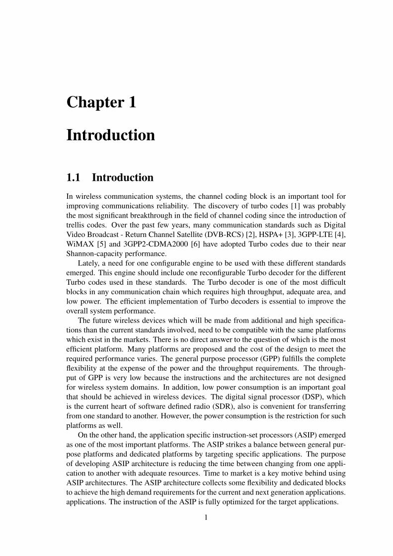
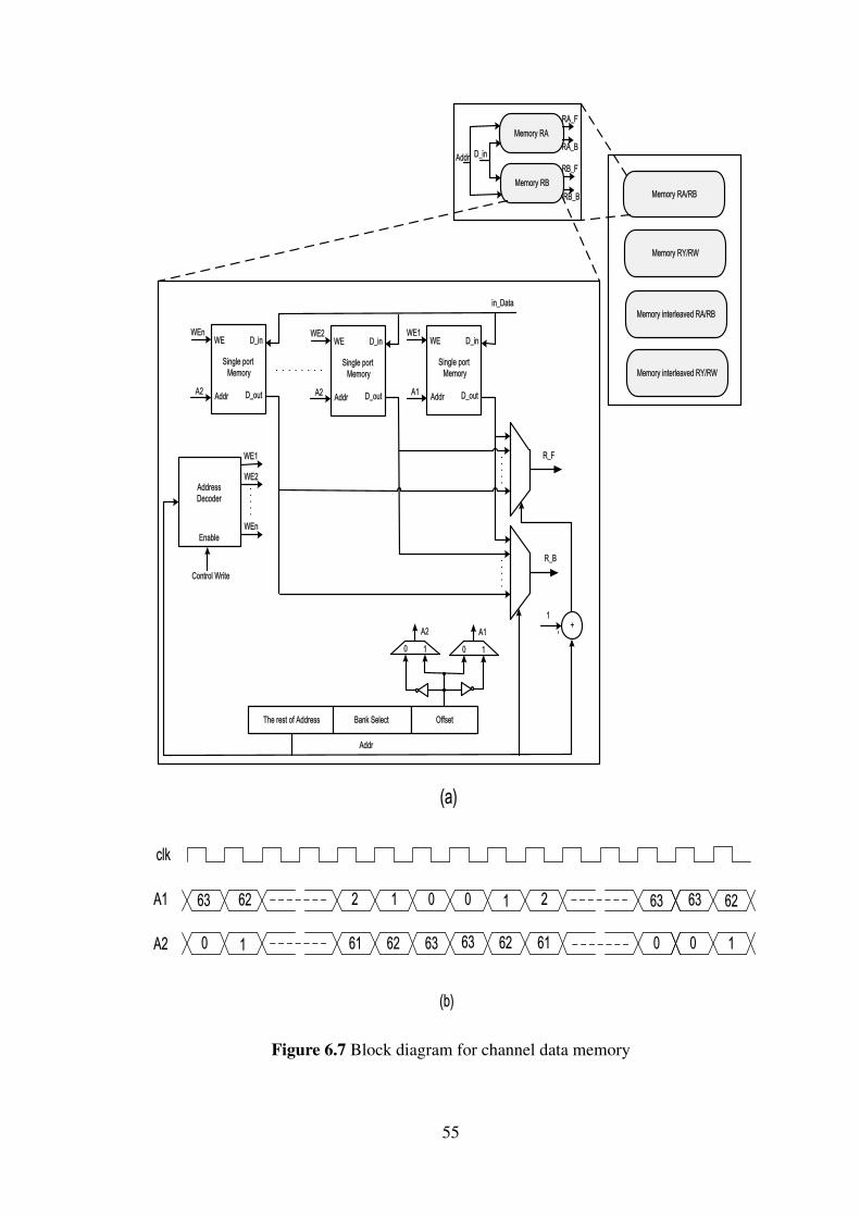
Both approaches lead to contention on memory due to parallel access, resulting inmemory conflicts. An example of these conflicts is shown in Figure 1.1 where fourprocessing elements (PE) are writing simultaneously with interleaved addresses whichlead to contentions on memory bank 2.
PE
1
PE
2
PE
3
PE
4
Bank
1
Bank
2
Bank
3
Bank
4
Figure 1.1 Contention on memory bank 2, three simultaneous writing attemptsfrom processing elements (PE) 1, 3 and 4 to memory bank 2.
Another source of memory conflicts is the interleavers contained in Turbo codes. Theinterleaver patterns affect the memory conflicts. There are two types of interleavers, un-constrained interleavers and constrained interleavers. The constrained interleavers arecalled maximum contention free (MCF) [12] which mean no conflicts occur due to par-allel accesses. There are few standards that include contention-free interleavers such asWiMAX and 3GPP-LTE.
1.2 Prior WorkOver the past few years, several research groups tried to propose ASIP architectures.Specifically, the parallel Turbo decoder designs and its effects on the memory conflictshave received much attention.
2
1.2.1 Parallel Memory AccessIn [13] and [14], the authors propose a unified parallel radix-4 Turbo decoder architec-ture to support WiMAX and 3GPP-LTE standards in order to benefit from the maximumcontention free properties for these standards. However, these works are limited by inter-leavers properties and can not support the other remaining standards.
In [15], the authors propose a memory mapping algorithm avoiding any contention bycascading three different layers of permutations. The proposed method does not optimizeneither the cost of the architecture nor the throughput due to the latency resulting fromexecuting the algorithm. In [16] the avoidance of conflicting access is done throughbuilding a network of General-Interleaved-Bottleneck-Breaker nodes (GIBB) based on arandom graph generation algorithm. These nodes are not efficient to be a backbone ofthe network because they require complex routing and many resources.
In [17] buffering of the conflicting data until processed by the targeted memory wasproposed to avoid memory contentions. However, the way to determine the size of thebuffers was not efficient. The size was obtained at design time by profiling the RTL-model. In addition, the scheme supported only one standard, which is not suitable formulti-standard configurations.
In [18] the authors propose buffer architecture based on analysis of memory conflicts.This work reduces the area and offers higher operating frequencies by selecting the sizeof the buffers based on a standard case instead of the worst case. The stalling mechanismhas been produced to treat the worst-case situations adding variable delay dependent onthe block length. These features make the scheme not suitable for constrained real timesystems.
A good analysis of memory conflicts for multi-standards Turbo decoders is providedin [19]. However, the memory conflicts for the unified parallel radix-4 Turbo decoderand some standards such 3GPP2-CDMA2000 have not been analyzed. The analysis ofmemory conflicts for a unified parallel radix-4 Turbo decoder is provided in [10]. Ahigher number of extra cycles have been added to avoid the contentions on memories perhalf-iteration for HSPA+ standard. Furthermore bigger FIFO sizes have been used.
1.2.2 Unified and ASIP Turbo Decoder WorksThe authors in [20] proposed a unified architecture for supporting the Turbo codes ofWiMAX and UMTS. The parallel decoding is used for Turbo codes of WiMAX whichrequires higher throughput than Turbo codes of UMTS. In this design, the Turbo decoderof UMTS is designed without parallel architecture due to a lower throughput requirement.This leads to a low efficiency in the usage of the hardware resources. For UMTS case,the design uses full hardware resources by reducing the clock frequency.In addition, thedesign can handle the collisions which happen due to the parallel access for UMTS caseand without complicated mechanisms.
The authors in [21] show a pipelined ASIP processor which supports two types ofTurbo codes. The throughput of the design is 34Mbps and 17Mbps at five iterationsfor duo-binary and binary Turbo codes respectively. Such design is not suitable for 4Gwireless communication standards as it can not satisfy the throughput requirement.
A multi-processor platform based on a reconfigurable ASIP processor for the appli-cation domain of channel decoding is presented in [22]. The flexibility of that design isvery poor as the duo-binary Turbo codes are not implemented. The duo-binary Turbo
3
codes emerged in many standards such as WiMAX, DVB-RCS and DVB-RCT.The proposed ASIP-based multiprocessor architecture in [23] is based on the shuffled
decoding technique. The shuffled decoding technique allows two MAP decoders concur-rently working and passing the extrinsic LLRs. The presented ASIP can process theduo-binary schemes twice faster than the single binary schemes. This leads to significantdegradation in the hardware utilization in case of the single binary schemes.
A Turbo Decoder implementation on a multi-processor platform based on sub-blockparallelization is proposed in [24]. The authors proposed two configurations to handlethe topology to connect the multi-processors. Both configurations take large numberof cycles for producing the LLRs which lead to large degradation on the throughput.The proposed work achieves a throughput of 22.64 Mb/s by using 16 parallel processorswith 5 iterations. The proposed processor is not designed using ASIP technique. Suchconfigurations are not suitable for high throughput requirements.
The authors in [25] presented a programmable SIMD-based (Single Instruction Mul-tiple Data) DSP architecture for SDR that includes a set of architectural features to accel-erate Turbo decoder computations. The proposed SIMD processor supports the parallelcomputations. However the proposed design is more flexible as it targets software designsat the expense of the dedicated blocks. This SW approach is not sufficient to achieve thethroughput and the power requirements for wireless devices.
In this thesis, ASIP architecture for a scalable and reconfigurable multi-standardTurbo decoder is proposed. In our architecture, we avoid using complex techniques tohandle the high-throughput demand and propose different implementations to achievegood hardware resources by building a unified architecture which is supporting differentclasses of Turbo codes. Our design offers a good compromise between the flexibility ofthe design which is required for transferring from one scheme to another and the demandsof wireless communication devices such as power consumption and throughput. In addi-tion, our work presents an analysis of the memory conflicts for a unified multi-standardTurbo decoder and provides efficient techniques to satisfy their requirements.
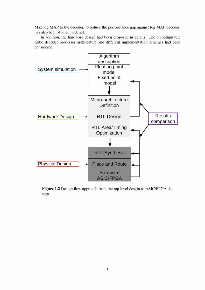
1.3 Design FlowThe typical RTL design approach, as shown in Figure 1.2, consists of three main steps:
• System simulation to ensure correct functionality, which is done using high levellanguages like MATLAB, C++ E
• Hardware design to implement the system towards the ASIC, which is done usingHardware description languages like VHDL, Verilog E
• Physical design to convert the obtained HDL into real chip.
The result comparisons are performed after each step to ensure the correctness of thedesign.
In the next chapters, the system simulations had been performed for the double-binaryconvolutional turbo Coding used in WiMAX IEEE 802.16e standard and single binaryconvolutional turbo Coding used in 3GPP-LTE. The influence of the turbo interleaverblock sizes, number of iterations, code rates, sliding window MAX Log MAP, and quan-tization of the internal signals have all been studied. An enhancement, by applying the
4
Max log MAP to the decoder, to reduce the performance gap against log MAP decoder,has also been studied in detail.
In addition, the hardware design had been proposed in details. The reconfigurableturbo decoder processor architecture and different implementation schemes had beenconsidered.
Algorithm
descriptionFloating point
modelFixed point
model
RTL Design
RTL Area/Timing
Optimization
Micro-architecture
Definition
System simulation
Hardware Design
Place and Route
Hardware
ASIC/FPGA
RTL Synthesis
Physical Design
Results
comparison
Figure 1.2 Design flow approach from the top level desgin to ASIC/FPGA de-sign
5
Chapter 2
Turbo Codes
2.1 IntroductionThere are two types of Turbo codes which are used in wireless communication systems:single binary and duo-binary Turbo codes. The single binary Turbo codes encode onebit at a time which is called radix-2 and is used in many standards such as 3GPP-LTE,HSPA+, and 3GPP2-CDMA2000. On the other side, the duo-binary Turbo codes encodetwo bits at a time which is called radix-4 and is used in WiMAX and DVB-RCS standards.
The details of the double-binary convolutional Turbo coding used in WiMAX IEEE802.16e standard and single binary convolutional Turbo Coding used in 3GPP-LTE arepresented. The decoding algorithms also are proposed for both types single and duo-binary Turbo codes.
2.2 WiMAX convolution Turbo code
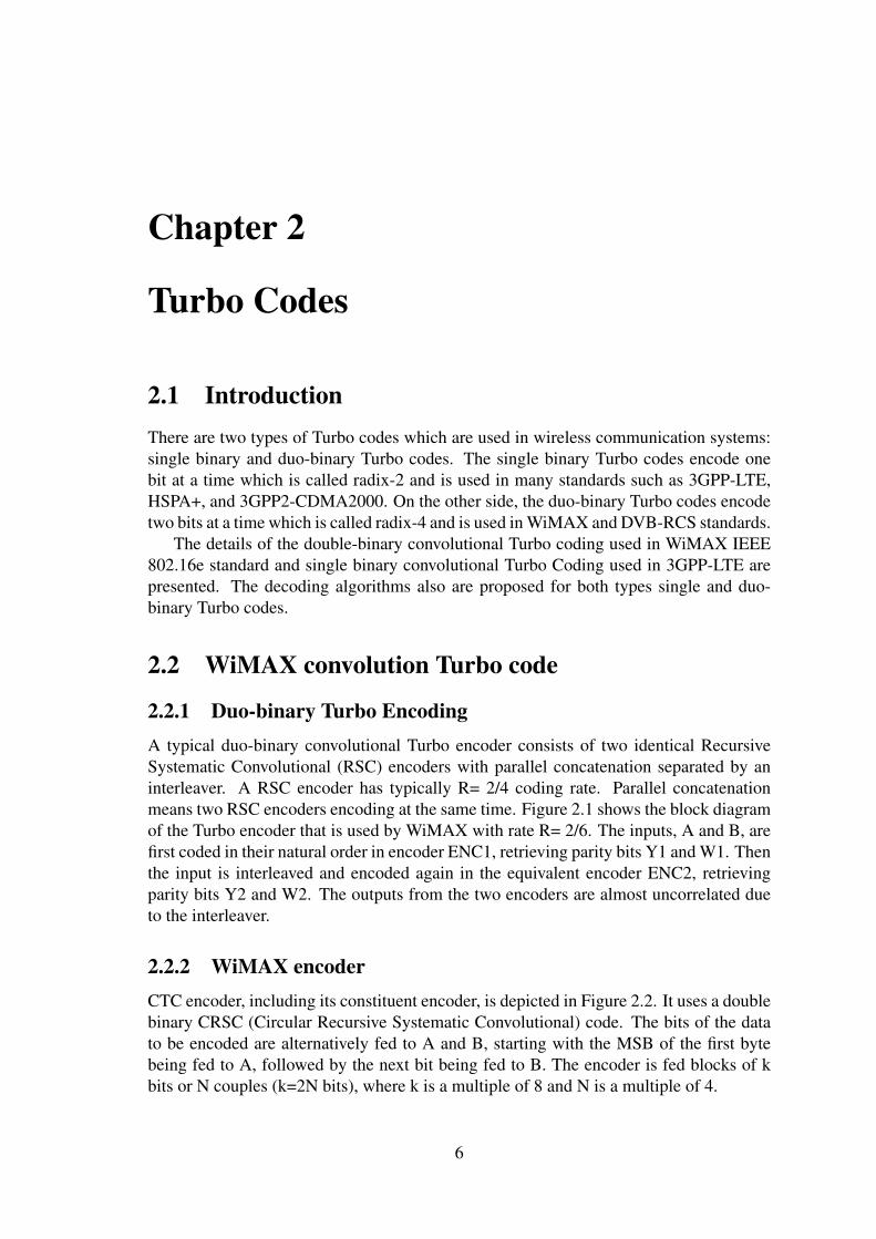
2.2.1 Duo-binary Turbo EncodingA typical duo-binary convolutional Turbo encoder consists of two identical RecursiveSystematic Convolutional (RSC) encoders with parallel concatenation separated by aninterleaver. A RSC encoder has typically R= 2/4 coding rate. Parallel concatenationmeans two RSC encoders encoding at the same time. Figure 2.1 shows the block diagramof the Turbo encoder that is used by WiMAX with rate R= 2/6. The inputs, A and B, arefirst coded in their natural order in encoder ENC1, retrieving parity bits Y1 and W1. Thenthe input is interleaved and encoded again in the equivalent encoder ENC2, retrievingparity bits Y2 and W2. The outputs from the two encoders are almost uncorrelated dueto the interleaver.
2.2.2 WiMAX encoderCTC encoder, including its constituent encoder, is depicted in Figure 2.2. It uses a doublebinary CRSC (Circular Recursive Systematic Convolutional) code. The bits of the datato be encoded are alternatively fed to A and B, starting with the MSB of the first bytebeing fed to A, followed by the next bit being fed to B. The encoder is fed blocks of kbits or N couples (k=2N bits), where k is a multiple of 8 and N is a multiple of 4.
6
ENC 1
ENC 2
Interleaver
A Y1
Y2
W2
W1B
A
B
Figure 2.1 Block diagram of Duo-binary CTC encoder
D
Internal
Interleaver
+ D
Constituent
Encoder
1
2 1Y 1W2Y 2W
A
B
Switch
+ D+
+
+
A
B
A
B
Systematic part
Party part
Constituent encoder
Figure 2.2 WiMAX CTC encoder
2.2.3 Internal interleaverThe CTC interleaver specified in IEEE802.16e consists of two permutation steps, one isa permutation on the level of each symbol individually, and the second is on the level ofthe sequence of all symbols. The two-step interleaver shall be performed by:
Step 1. Switch alternate couplesFor j = 0 to N−1I f ( jmod2 == 0) let(B,A) = (A,B)
Step 2. Pi( j)The function Pi( j) provides the interleaved address i of the considered couple j.For j = 0 to N−1Switch jmod4Case 0: i = (P0. j+1)mod NCase 1: i = (P0. j+1+N/2+P1)mod NCase 2: i = (P0. j+1+P2)mod N
7
Case 3: i = (P0. j+1+N/2+P3)mod N
Where P0, P1, P2 and P3 are coding parameters that are specific for each block size,N, and are provided in the standards. The address j is interleaved to address i. Table 2.3provides the combinations of the default parameters to be used
2.2.4 Circular state encodingThe tail biting scheme used in IEEE802.16e Turbo encoder is circular coding, this schemeguarantees that the initial state is the same as final state. The sequence of determinationof circulation states Sc1, Sc2 is:
• Initializing the encoder with state 0. Encode the sequence in the natural order forthe determination of Sc1 and in the interleaved order for determination of Sc2. Inboth cases the final state of the encoder is S0N−1
• According to the length N of the sequence, determining Sc1 or Sc2 as given in Table2.2
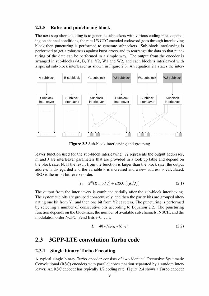
2.2.5 Rates and puncturing blockThe next step after encoding is to generate subpackets with various coding rates depend-ing on channel conditions, the rate 1/3 CTC encoded codeword goes through interleavingblock then puncturing is performed to generate subpackets. Sub-block interleaving isperformed to get a robustness against burst errors and to rearrange the data so that punc-turing of the data can be performed in a simple way. The output from the encoder isarranged in sub-blocks (A, B, Y1, Y2, W1 and W2) and each block is interleaved witha special sub-block interleaver as shown in Figure 2.3. An equation 2.1 states the inter-
Subblock
Interleaver
A subblock
Subblock
Interleaver
B subblock
Subblock
Interleaver
Y1 subblock
Subblock
Interleaver
Y2 subblock
Subblock
Interleaver
W1 subblock
Subblock
Interleaver
W2 subblock
Figure 2.3 Sub-block interleaving and grouping
leaver function used for the sub-block interleaving. Tk represents the output addresses;m and J are interleaver parameters that are provided in a look up table and depend onthe block size, N. If the result from the function is larger than the block size, the outputaddress is disregarded and the variable k is increased and a new address is calculated.BRO is the m-bit bit reverse order.
Tk = 2m(K mod J)+BROm(bK/Jc) (2.1)
The output from the interleavers is combined serially after the sub-block interleaving.The systematic bits are grouped consecutively, and then the parity bits are grouped alter-nating one bit from Y1 and then one bit from Y2 et cetera. The puncturing is performedby selecting a number of consecutive bits according to Equation 2.2. The puncturingfunction depends on the block size, the number of available sub channels, NSCH, and themodulation order NCPC. Send Bits i=0,. . . ,L
L = 48∗NSCH ∗NCPC (2.2)
2.3 3GPP-LTE convolution Turbo code
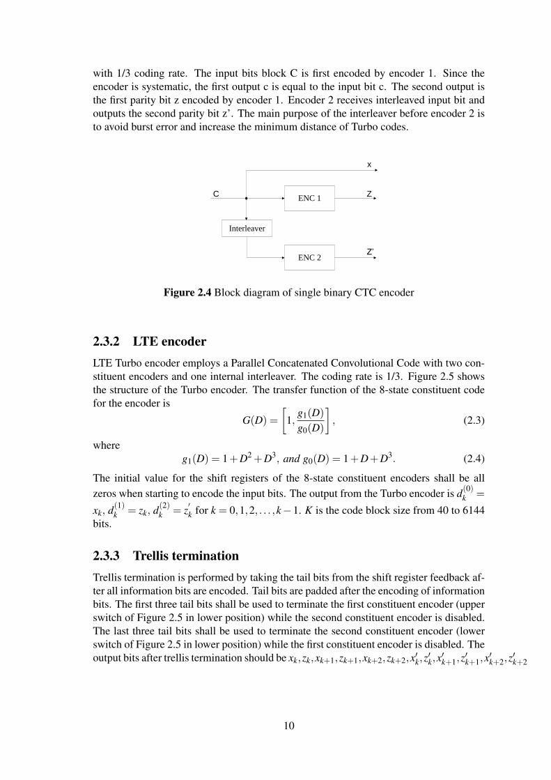
2.3.1 Single binary Turbo EncodingA typical single binary Turbo encoder consists of two identical Recursive SystematicConvolutional (RSC) encoders with parallel concatenation separated by a random inter-leaver. An RSC encoder has typically 1/2 coding rate. Figure 2.4 shows a Turbo encoder
9
with 1/3 coding rate. The input bits block C is first encoded by encoder 1. Since theencoder is systematic, the first output c is equal to the input bit c. The second output isthe first parity bit z encoded by encoder 1. Encoder 2 receives interleaved input bit andoutputs the second parity bit z’. The main purpose of the interleaver before encoder 2 isto avoid burst error and increase the minimum distance of Turbo codes.
ENC 1
ENC 2
Interleaver
Z’
ZC
x
Figure 2.4 Block diagram of single binary CTC encoder
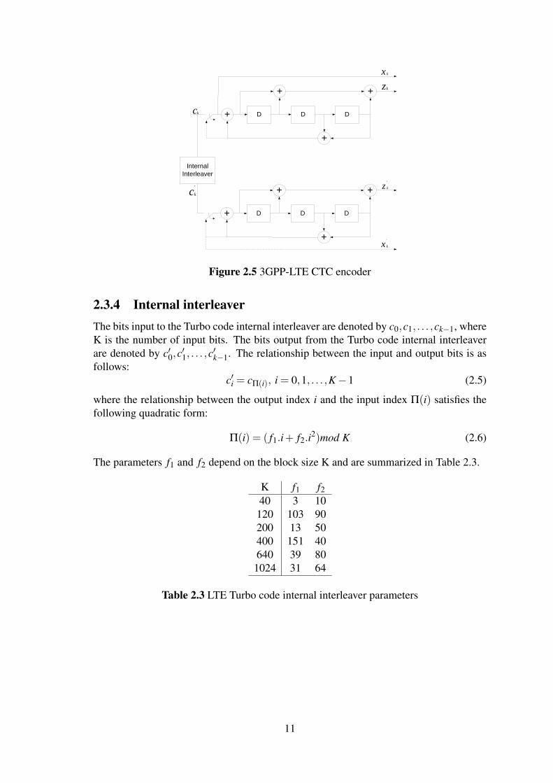
2.3.2 LTE encoderLTE Turbo encoder employs a Parallel Concatenated Convolutional Code with two con-stituent encoders and one internal interleaver. The coding rate is 1/3. Figure 2.5 showsthe structure of the Turbo encoder. The transfer function of the 8-state constituent codefor the encoder is
G(D) =
[1,
g1(D)
g0(D)
], (2.3)
whereg1(D) = 1+D2 +D3, and g0(D) = 1+D+D3. (2.4)
The initial value for the shift registers of the 8-state constituent encoders shall be allzeros when starting to encode the input bits. The output from the Turbo encoder is d(0)
k =
xk, d(1)k = zk, d(2)
k = z′k for k = 0,1,2, . . . ,k−1. K is the code block size from 40 to 6144
bits.
2.3.3 Trellis terminationTrellis termination is performed by taking the tail bits from the shift register feedback af-ter all information bits are encoded. Tail bits are padded after the encoding of informationbits. The first three tail bits shall be used to terminate the first constituent encoder (upperswitch of Figure 2.5 in lower position) while the second constituent encoder is disabled.The last three tail bits shall be used to terminate the second constituent encoder (lowerswitch of Figure 2.5 in lower position) while the first constituent encoder is disabled. Theoutput bits after trellis termination should be xk,zk,xk+1,zk+1,xk+2,zk+2,x′k,z
′k,x′k+1,z
′k+1,x
′k+2,z
′k+2
10
D
+
Internal
Interleaver
+ D D
+
+
D
+
+ D D
+
+
kx
kz
'
kz
kc
'
kc
'
kx
Figure 2.5 3GPP-LTE CTC encoder
2.3.4 Internal interleaverThe bits input to the Turbo code internal interleaver are denoted by c0,c1, . . . ,ck−1, whereK is the number of input bits. The bits output from the Turbo code internal interleaverare denoted by c′0,c
′1, . . . ,c
′k−1. The relationship between the input and output bits is as
follows:c′i = cΠ(i), i = 0,1, . . . ,K−1 (2.5)
where the relationship between the output index i and the input index Π(i) satisfies thefollowing quadratic form:
Π(i) = ( f1.i+ f2.i2)mod K (2.6)
The parameters f1 and f2 depend on the block size K and are summarized in Table 2.3.
K f1 f240 3 10120 103 90200 13 50400 151 40640 39 80
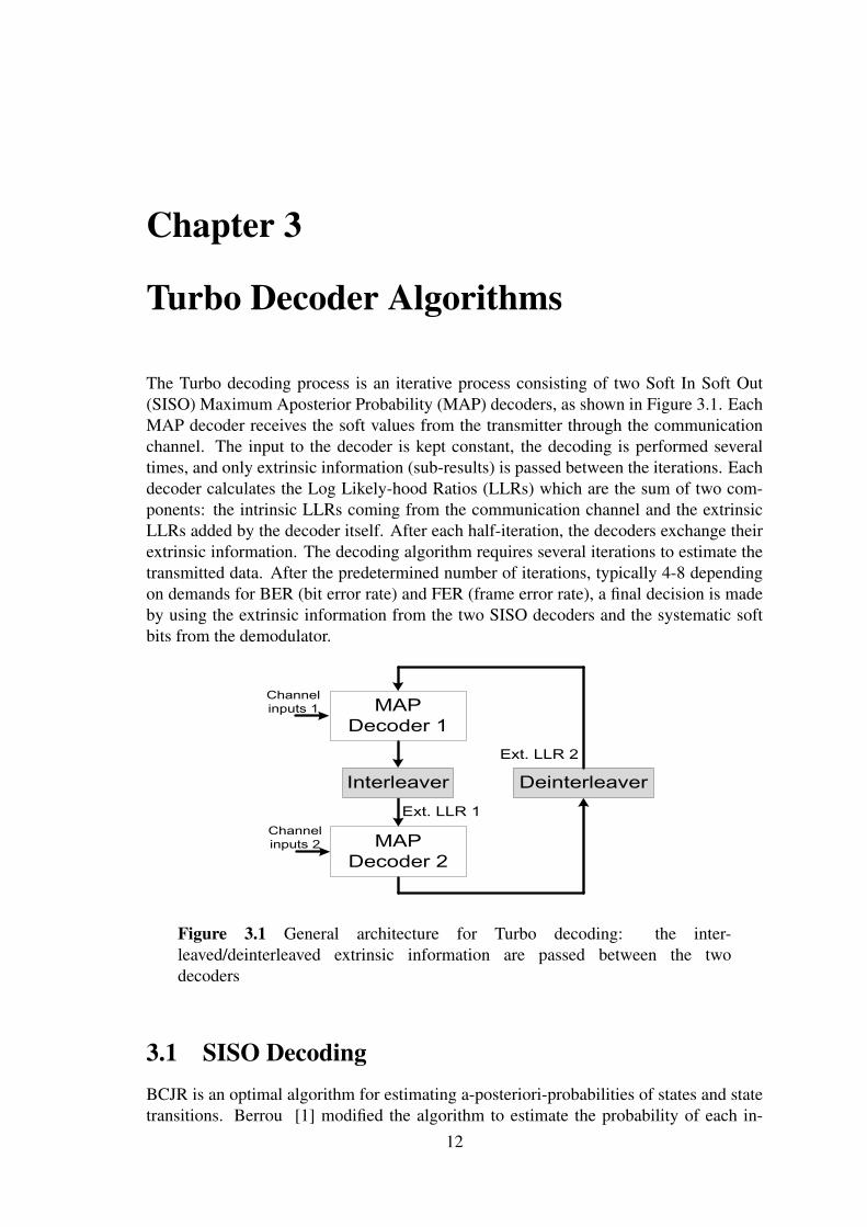
The Turbo decoding process is an iterative process consisting of two Soft In Soft Out(SISO) Maximum Aposterior Probability (MAP) decoders, as shown in Figure 3.1. EachMAP decoder receives the soft values from the transmitter through the communicationchannel. The input to the decoder is kept constant, the decoding is performed severaltimes, and only extrinsic information (sub-results) is passed between the iterations. Eachdecoder calculates the Log Likely-hood Ratios (LLRs) which are the sum of two com-ponents: the intrinsic LLRs coming from the communication channel and the extrinsicLLRs added by the decoder itself. After each half-iteration, the decoders exchange theirextrinsic information. The decoding algorithm requires several iterations to estimate thetransmitted data. After the predetermined number of iterations, typically 4-8 dependingon demands for BER (bit error rate) and FER (frame error rate), a final decision is madeby using the extrinsic information from the two SISO decoders and the systematic softbits from the demodulator.
MAP
Decoder 1
MAP
Decoder 2
Interleaver Deinterleaver
Channel
inputs 1
Channel
inputs 2
Ext. LLR 1
Ext. LLR 2
Figure 3.1 General architecture for Turbo decoding: the inter-leaved/deinterleaved extrinsic information are passed between the twodecoders
3.1 SISO DecodingBCJR is an optimal algorithm for estimating a-posteriori-probabilities of states and statetransitions. Berrou [1] modified the algorithm to estimate the probability of each in-
12
formation bit (for binary codes, pair of information bits for duo binary codes). Themodification of the algorithm is often referred to as the MAP (maximum a posteriori)algorithm. It is suitable for iterative turbo decoding because it is a SISO. An importantproperty is that the soft output data can be used in the next iteration to calculate more ac-curate values. All calculations in the MAP algorithm are performed in the log domain toavoid numerical problems and unnecessary multiplications; the algorithm is then calledthe log-MAP algorithm. The MAP algorithm requires many multiplications and divi-sions. All calculations in the MAP algorithm are performed in the log domain to avoidnumerical problems and unnecessary multiplications; the algorithm is then called thelog-MAP algorithm. Nevertheless the log-MAP algorithm is complex and requires ex-tensive hardware resources. Many simplified versions of MAP algorithm were proposedto be suitable for hardware implementation such as linear-log-MAP, constant-log-MAPand Max-log-MAP [26]. The performance degradation due to simplification in MAPalgorithm can be compensated by using an enhancement Max-Log-MAP where a scalingfactor scales the extrinsic LLRs.
3.2 Log-MAPIn the decoding process, the goal is to calculate an accurate a-posteriori-probability forthe received block that can be used to make a hard decision by guessing on the largestAPP for each information bit (for binary codes, pair of information bits for duo binarycodes) when all iterations are complete. Equation 3.1 represents the APP that can becalculated iteratively by calculating the metrics in Equations 3.2, 3.3 and 3.4.
The values of b ∈ {0,1} depends on the encoding polynomial and can be pre-calculatedfor all state transitions, respectively. The extrinsic information from the last stage isdenoted lnP(uk) and y = {A,B,Y,W} represents the noisy soft input values, where s isthe current state and s′ is the the transition state. The parameters α , β and γ are explainedin detail later.Extrinsic information for the next stage is calculated according to Equation 3.5.
The high complexity equations above can be implemented by using a rearranged versionof the function,Equation 3.6, and using look up tables for the correction term. A betterimplemented correction term gives better error correction capability. Constant-log-MAPand linear-log-MAP are two implementation of the SISO algorithm with different correc-tion terms.
3.3 Max-log-MAPMax-log-MAP is a simplification of the log-MAP algorithm that makes the estimationstated in Equation 3.7; i.e. disregard the correction term.
ln(ex1 + · · ·+ exn)≈ max(x1, . . . ,xn) (3.7)
Lower complexity usually brings some disadvantages and that is the case here: the errorcorrecting capability is degraded for this algorithm. This improvement in robustness isexplained by Berrou et al in [27].
In this thesis, the max-log-MAP decoding algorithm [28] will be used. As it has lowcomputational complexity, it is widely used for SISO decoding in the turbo decoder. Themax-log-MAP algorithm includes one forward and one backward recursion through thereceived soft input data and a number of different metrics are calculated, these will beexplained in detail.
As mentioned earlier, there are two types for Turbo codes: single binary and duo-binary Turbo codes. The single binary Turbo codes decode one bit at time which calledradix-2. On the other side, the duo-binary Turbo codes decode two bits at time whichcalled radix-4. The extrinsic LLR is calculated from three metrics: forward states, back-ward states and branch metrics.
3.3.1 Branch State MetricThe Turbo codes can be defined using a trellis where at every time k there exist the samenumber of possible states. Define γ
( j)k (sk−1,sk) as the branch metrics between the state
sk at time k and state sk−1 at time k− 1 and j represents the different combinations ofthe systematic bits, where j ∈ [0,1] for radix-2 scheme and j ∈ [00,10,01,11] for radix-4 scheme. The metric γ
( j)k (sk−1,sk) represents the probability that a transition between
these two states occurred. The branch metric γ( j)k (sk−1,sk) can be calculated from
γ( j)k (sk−1,sk) =
m
∑j=1
xk, jyk, j +Λ( j)apr,k (3.8)
where the branch metric depends on the received soft inputs yk, j , the extrinsic informa-
tion received from previous decoding iteration and re-named apriori information Λ( j)apr,k
and the possible transmitted bits xk, j ∈ {0,1} .
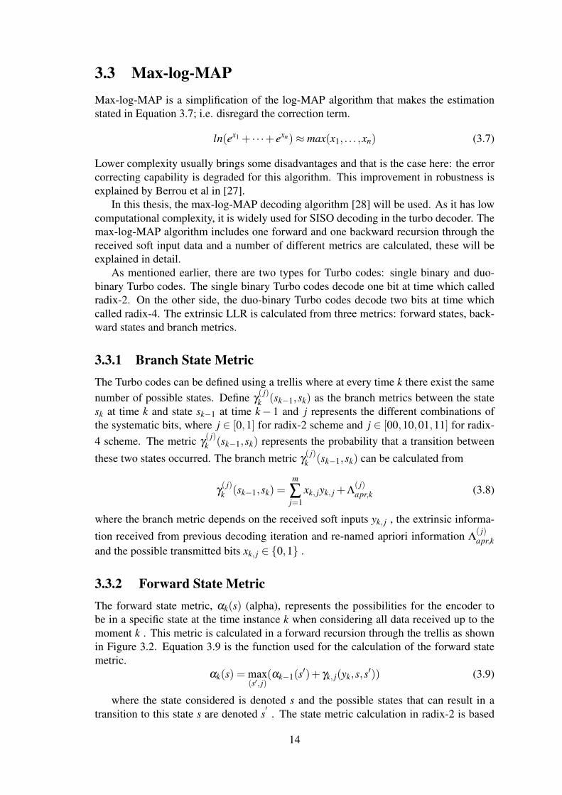
3.3.2 Forward State MetricThe forward state metric, αk(s) (alpha), represents the possibilities for the encoder tobe in a specific state at the time instance k when considering all data received up to themoment k . This metric is calculated in a forward recursion through the trellis as shownin Figure 3.2. Equation 3.9 is the function used for the calculation of the forward statemetric.
αk(s) = max(s′, j)
(αk−1(s′)+ γk, j(yk,s,s′)) (3.9)
where the state considered is denoted s and the possible states that can result in atransition to this state s are denoted s
′. The state metric calculation in radix-2 is based
14
1(0)
k
1(1)
k
1(2)
k
1(3)
k
1(4)
k
1(5)
k
1(6)
k
1(7)
k
(4)k
z=00
z=01
z=10
z=11
1(0)
k
1(1)
k
1(2)
k
1(3)
k
1(4)
k
1(5)
k
1(6)
k
1(7)
k
(4)k
z=0
z=1
(a) (b)
Figure 3.2 Calculation of one forward state metric, alpha, (a) for Duo-binarycodes and (b) for single binary codes
on the maximum between two branches while it is the maximum between four branchesin case of radix-4.
Figure 3.2 is an example of how the alpha calculation is performed. The value attime instance k for state 4 is calculated by taking the largest value from the alpha valuesin four states 0, 1, 6 and 7 at k-1 for duo-binary case while in the single binary caseby taking the largest value from the alpha values in two states 1and 5. Each of the oldalpha values are added with the corresponding gamma value from s to s
′. In duo-binary
case, the upper arrow represents a transition caused by input j = 102 (the red line) sothe gamma value includes APP information retrieved from the last iteration for a 102-transition. The gamma value will also include a comparison of the soft bits with theoutput that the encoder would generate in a transition from state 0 with input j = 102.
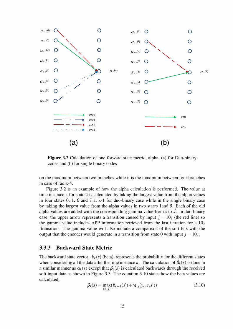
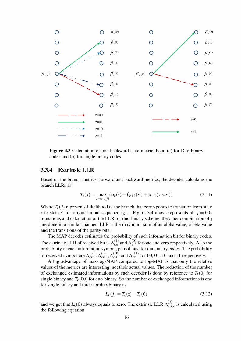
3.3.3 Backward State MetricThe backward state vector , βk(s) (beta), represents the probability for the different stateswhen considering all the data after the time instance k . The calculation of βk(s) is done ina similar manner as αk(s) except that βk(s) is calculated backwards through the receivedsoft input data as shown in Figure 3.3. The equation 3.10 states how the beta values arecalculated.
βk(s) = max(s′, j)
(βk−1(s′)+ γk, j(yk,s,s′)) (3.10)
15
(0)k
(1)k
(2)k
(3)k
(4)k
(5)k
(6)k
(7)k
z=00
z=01
z=10
z=11
1(4)
k
(0)k
(1)k
(2)k
(3)k
(4)k
(5)k
(6)k
(7)k
z=0
z=1
1(4)
k
Figure 3.3 Calculation of one backward state metric, beta, (a) for Duo-binarycodes and (b) for single binary codes
3.3.4 Extrinsic LLRBased on the branch metrics, forward and backward metrics, the decoder calculates thebranch LLRs as
Tk( j) = maxs→s′:( j)
(αk(s)+βk+1(s′)+ γk−1(y,s,s′)) (3.11)
Where Tk( j) represents Likelihood of the branch that corresponds to transition from states to state s′ for original input sequence (z) . Figure 3.4 above represents all j = 002transitions and calculation of the LLR for duo-binary scheme, the other combination of jare done in a similar manner. LLR is the maximum sum of an alpha value, a beta valueand the transitions of the parity bits.
The MAP decoder estimates the probability of each information bit for binary codes.The extrinsic LLR of received bit is Λ
(1)ext and Λ
(0)ext for one and zero respectively. Also the
probability of each information symbol, pair of bits, for duo binary codes. The probabilityof received symbol are Λ
(00)ext ,Λ
(01)ext ,Λ
(10)ext and Λ
(11)ext for 00, 01, 10 and 11 respectively.
A big advantage of max-log-MAP compared to log-MAP is that only the relativevalues of the metrics are interesting, not their actual values. The reduction of the numberof exchanged estimated informations by each decoder is done by reference to Tk(0) forsingle binary and Tk(00) for duo-binary. So the number of exchanged informations is onefor single binary and three for duo-binary as
Lk( j) = Tk(z)−Tk(0) (3.12)
and we get that Lk(0) always equals to zero. The extrinsic LLR Λ( j)ext,k is calculated using
the following equation:16
(0)k
(1)k
(2)k
(3)k
(4)k
(5)k
(6)k
(7)k
1(0)
k
1(1)
k
1(2)
k
1(3)
k
1(4)
k
1(5)
k
1(6)
k
1(7)
k
Figure 3.4 Calculation of LLR
Λ( j)ext,k = Lk( j)−Λ
( j)apr,k− yk, j (3.13)
After calculation of branch LLRs, three extrinsic LLRs Λ(11)ext,k, Λ
(10)ext,k, Λ
(01)ext,k should be
bypassed to the other component decoder.The final decision of decoded bits for duo-binary Turbo codes scheme is performed
according to the sign of the output LLRs obtained from Equation 3.14.
After Calculation of both Lk(A), Lk(B), we are able to estimate both original informationbits A, B. This should be done at the last decoding iteration.
The final decision of decoded bits for single binary Turbo codes scheme is performedaccording to the sign of the output LLRs, Lk(1), obtained from Equation 3.12.
3.4 Unified Radix-4 decoding algorithmFor single binary turbo codes, the trellis cycles can be reduced 50% by applying the one-level look-ahead recursion [29] [30] as illustrated in Fig. 3.5. Radix-4 α recursion is thengiven by:
αk(sk) = maxsk−1{max
sk−2{αk−2(sk−2)+ γk−1(sk−2,sk−1)}+ γk(sk−1,sk)}
= maxsk−2,sk−1
{αk−2(sk−2)+ γk(sk−2,sk)}(3.15)
where γk(sk−2,sk) is the new branch meteric for the two-bit symbol{Ak−1,Ak} connectingstate sk−2 and sk: Similarly, Radix-4 β recursion is computed as:
βk(sk) = maxsk+2,sk+1
{βk+2(sk+2)+ γk(sk,sk+2)} (3.16)
17
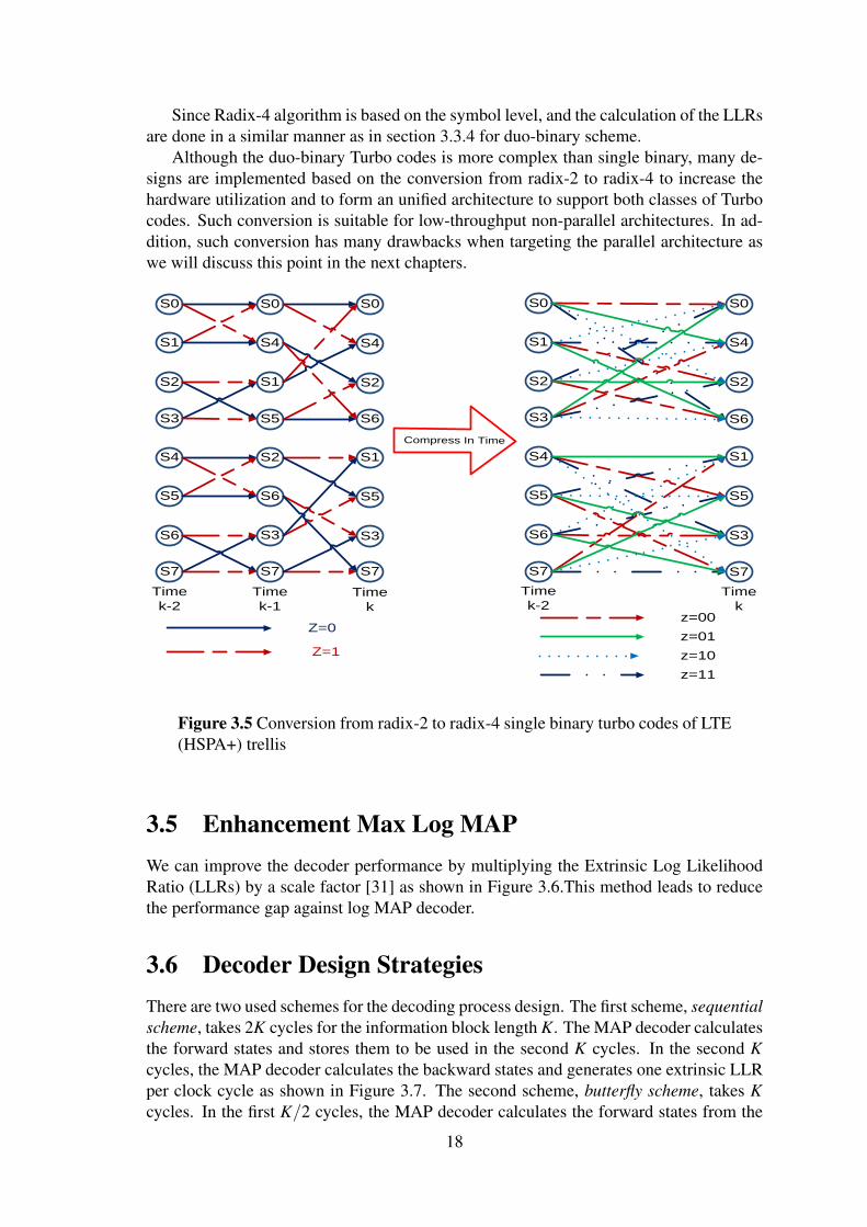
Since Radix-4 algorithm is based on the symbol level, and the calculation of the LLRsare done in a similar manner as in section 3.3.4 for duo-binary scheme.
Although the duo-binary Turbo codes is more complex than single binary, many de-signs are implemented based on the conversion from radix-2 to radix-4 to increase thehardware utilization and to form an unified architecture to support both classes of Turbocodes. Such conversion is suitable for low-throughput non-parallel architectures. In ad-dition, such conversion has many drawbacks when targeting the parallel architecture aswe will discuss this point in the next chapters.
S0
Z=1
S1
S2
S3
S0
S4
S1
S5
Z=0
S4
S5
S6
S7
S2
S6
S3
S7
S0
S4
S2
S6
S1
S5
S3
S7
Time
k-2
Time
k-1Time
k
Compress In Time
S0
S1
S2
S3
S4
S5
S6
S7
S0
S4
S2
S6
S1
S5
S3
S7
Time
k-2Time
kz=00
z=01
z=10
z=11
Figure 3.5 Conversion from radix-2 to radix-4 single binary turbo codes of LTE(HSPA+) trellis
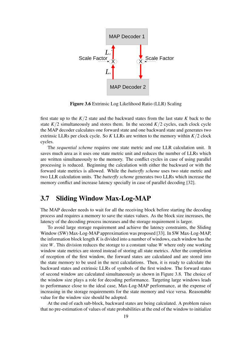
3.5 Enhancement Max Log MAPWe can improve the decoder performance by multiplying the Extrinsic Log LikelihoodRatio (LLRs) by a scale factor [31] as shown in Figure 3.6.This method leads to reducethe performance gap against log MAP decoder.
3.6 Decoder Design StrategiesThere are two used schemes for the decoding process design. The first scheme, sequentialscheme, takes 2K cycles for the information block length K. The MAP decoder calculatesthe forward states and stores them to be used in the second K cycles. In the second Kcycles, the MAP decoder calculates the backward states and generates one extrinsic LLRper clock cycle as shown in Figure 3.7. The second scheme, butterfly scheme, takes Kcycles. In the first K/2 cycles, the MAP decoder calculates the forward states from the
18
MAP Decoder 1
X
MAP Decoder 2
XScale Factor
eL
'eL
Scale Factor
Figure 3.6 Extrinsic Log Likelihood Ratio (LLR) Scaling
first state up to the K/2 state and the backward states from the last state K back to thestate K/2 simultaneously and stores them. In the second K/2 cycles, each clock cyclethe MAP decoder calculates one forward state and one backward state and generates twoextrinsic LLRs per clock cycle. So K LLRs are written to the memory within K/2 clockcycles.
The sequential scheme requires one state metric and one LLR calculation unit. Itsaves much area as it uses one state metric unit and reduces the number of LLRs whichare written simultaneously to the memory. The conflict cycles in case of using parallelprocessing is reduced. Beginning the calculation with either the backward or with theforward state metrics is allowed. While the butterfly scheme uses two state metric andtwo LLR calculation units. The butterfly scheme generates two LLRs which increase thememory conflict and increase latency specially in case of parallel decoding [32].
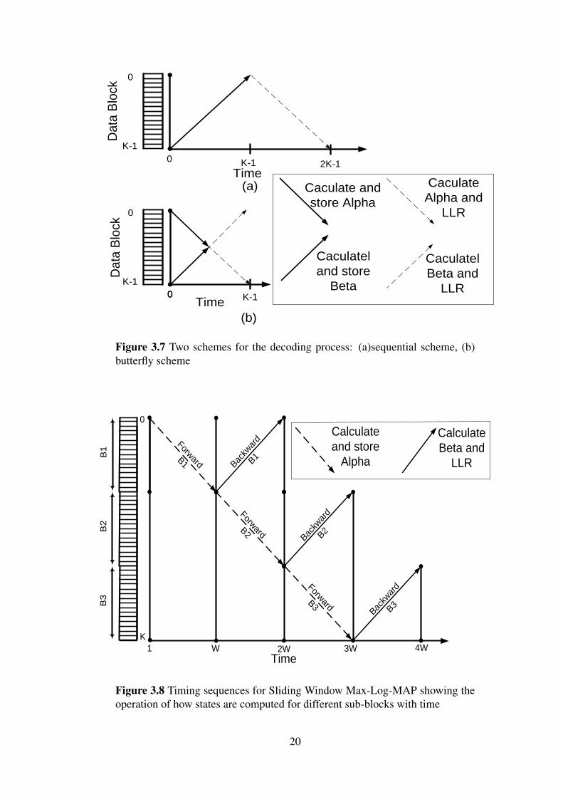
3.7 Sliding Window Max-Log-MAPThe MAP decoder needs to wait for all the receiving block before starting the decodingprocess and requires a memory to save the states values. As the block size increases, thelatency of the decoding process increases and the storage requirement is larger.
To avoid large storage requirement and achieve the latency constraints, the SlidingWindow (SW) Max-Log-MAP approximation was proposed [33]. In SW Max-Log-MAP,the information block length K is divided into a number of windows, each window has thesize W . This division reduces the storage to a constant value W where only one workingwindow state metrics are stored instead of storing all state metrics. After the completionof reception of the first window, the forward states are calculated and are stored intothe state memory to be used in the next calculations. Then, it is ready to calculate thebackward states and extrinsic LLRs of symbols of the first window. The forward statesof second window are calculated simultaneously as shown in Figure 3.8. The choice ofthe window size plays a role for decoding performance. Targeting large windows leadsto performance close to the ideal case, Max-Log-MAP performance, at the expense ofincreasing in the storage requirements for the state memory and vice versa. Reasonablevalue for the window size should be adopted.
At the end of each sub-block, backward states are being calculated. A problem raisesthat no pre-estimation of values of state probabilities at the end of the window to initialize
19
Da
ta B
lock
0 K-1
Time
0
K-1
2K-1
(a)
Time0
0
K-1
0 K-1
Caculate and
store Alpha
Caculatel
and store
Beta
Caculate
Alpha and
LLR
Caculatel
Beta and
LLR
Da
ta B
lock
(b)
Figure 3.7 Two schemes for the decoding process: (a)sequential scheme, (b)butterfly scheme
1 W 2WTime
3W
Bac
kwar
d
B1
Forward
B3
Bac
kwar
d
B2
Forward
B2
Forward
B1
Bac
kwar
d
B3
4W
B1
B2
B3
0
K
Calculate
and store
Alpha
Calculate
Beta and
LLR
Figure 3.8 Timing sequences for Sliding Window Max-Log-MAP showing theoperation of how states are computed for different sub-blocks with time
20
backward states. A possible solution is to assume equiprobable states at this time slot.This has its impact on degrading the system performance.
In order to overcome the effect of performance degradation, some proposed tech-niques use a guard window to have a rough estimation of initial value of backward statemetrics. The guard window begins tracing back not from the end of the current window,but from a further time slot in the next window, this depends on the guard window size.As window size and guard window size increases, we have a better performance. Theprocess of SW MAX Log MAP using a guard window is shown in Figure 3.9
0 W W+g 2W 2W+g 3W 3W+g 4W 4W+g
5W
1-Forward
1-Backward
2-Forward
2-Backward
3-Forward
3-Backward
4-Forward
4-Backward
5-Forward
5-Backward
Figure 3.9 Sliding Window operation using a guard window technique
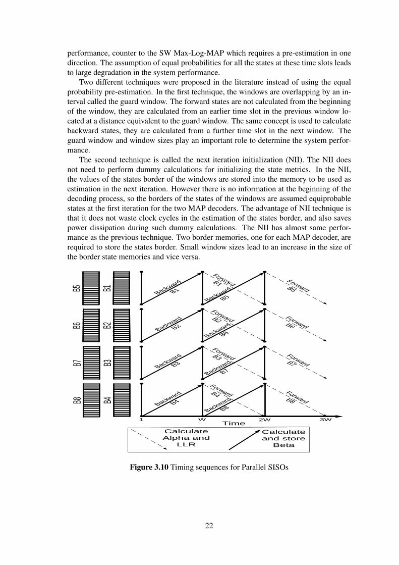
3.8 Parallel Sliding Window First SchemeAs mentioned earlier, parallel decoding is used to increase the throughput. The currentwireless communication systems require high-throughput. The parallel decoding [8] [9]is used to increase the throughput. Parallel decoding can be employed by dividing thewhole information block into p sub-blocks, each is processed independently by a dedi-cated SISO decoder [34]. Each sub-block is again divided into several windows of lengthW . Each window operation takes 2W cycles. In the first W cycles, each SISO decodercalculates backward states and stores them to be used in the second W cycles. In the sec-ond W cycles, the SISO decoders simultaneously calculate forward states and generateextrinsic LLRs. At the same time in which the forward calculations are executed, thebackward calculations of the next window are processed. At the last W cycles, the for-ward states and extrinsic LLRs of the remaining windows are calculated. However thereis an overlap between forward and backward states generations, only W LLRs are writtento the memory within W clock cycles for each SISO. A timing sequence description ofthe Parallel SW Max-Log-MAP algorithm is provided in Figure 3.10.
Another problem is raised which is similar to SW Max-Log-MAP, due to handlingthe received block as independent windows, we need to have a pre-estimation for stateprobabilities at the end of the window to initialize the backward states and at the begin-ning of the window to initialize the forward states. The pre-estimation is required forboth the forward and backward metrics which leads to large degradation in the decoding
21
performance, counter to the SW Max-Log-MAP which requires a pre-estimation in onedirection. The assumption of equal probabilities for all the states at these time slots leadsto large degradation in the system performance.
Two different techniques were proposed in the literature instead of using the equalprobability pre-estimation. In the first technique, the windows are overlapping by an in-terval called the guard window. The forward states are not calculated from the beginningof the window, they are calculated from an earlier time slot in the previous window lo-cated at a distance equivalent to the guard window. The same concept is used to calculatebackward states, they are calculated from a further time slot in the next window. Theguard window and window sizes play an important role to determine the system perfor-mance.
The second technique is called the next iteration initialization (NII). The NII doesnot need to perform dummy calculations for initializing the state metrics. In the NII,the values of the states border of the windows are stored into the memory to be used asestimation in the next iteration. However there is no information at the beginning of thedecoding process, so the borders of the states of the windows are assumed equiprobablestates at the first iteration for the two MAP decoders. The advantage of NII technique isthat it does not waste clock cycles in the estimation of the states border, and also savespower dissipation during such dummy calculations. The NII has almost same perfor-mance as the previous technique. Two border memories, one for each MAP decoder, arerequired to store the states border. Small window sizes lead to an increase in the size ofthe border state memories and vice versa.
1 W 2WTime
Backward
B1
Backward
B5
Forward B1
Forward B5
3W
Backward
B2
Backward
B6
Forward B2Forward B6
Backward
B3
Backward
B7
Forward B3
Forward B7
Backward
B4
Backward
B8
Forward B4 Forward B8
Calculate
Alpha and
LLR
Calculate
and store
Beta
B1B5
B2B6
B3B7
B4B8
Figure 3.10 Timing sequences for Parallel SISOs
22
3.9 Parallel Sliding Window Second SchemeThe parallel decoding in second scheme can also be employed by dividing the wholeinformation block into p sub-blocks similarly to the previous case. In this scheme, eachwindow operation takes W cycles. In the first W/2 cycles, each SISO decoder calculatesforward and backward states and stores them to be used in the second W/2 cycles. In thesecond W/2 cycles, each SISO decoder generates two extrinsic LLRs per clock cycle,which means that W LLRs are written to the memory within W/2 clock cycles as shownin Fig. 3.11.
This scheme takes less time than the previous parallel decoding. However large la-tency is added to the decoding time due to the increase of the number of LLR data whichwill be written to the memory simultaneously. Such large latency will degrade on thethroughput significantly. To overcome such degradation, many methods are proposed tohandle and to improve throughput than the original case. These methods will be discussedin the next chapters.
WTime
B1B5
B2B6
B3B7
B4B8
Backward
B1
Forward B1
Backward
B5
Forward B5
Backward
B2
Forward B2
Backward
B6
Forward B6
Backward
B3
Forward B3
Backward
B7
Forward B7
Backward
B4
Forward B4
Backward
B8
Forward B8
2W1
Caculate and
store Alpha
Caculatel and
store Beta
Caculate
Alpha and LLR
Caculatel
Beta and LLR
Figure 3.11 Timing sequences for Parallel SISOs Butterfly Scheme
3.10 Trellis TerminationStarting and ending from known states at the encoder results in better performance at thedecoders. There are two trellis termination mechanisms used in the current standards.In the first mechanism, the encoder starts from the zero state and tail bitting is used toensure that we end at the zero state. In the second mechanism, the encoder makes sure itstarts and ends in the same state. This does not need tail bitting and does not affect thethroughput of small block sizes.
23
Chapter 4
Simulations of WiMAX and 3GPP-LTETurbo Codes
The simulations of double-binary convolutional Turbo coding which is used in WiMAXIEEE 802.16e standard and single binary convolutional Turbo Coding which is used in3GPP-LTE [35] are presented, showing that influence of the Turbo interleaver block sizes,number of iterations, code rates, sliding window MAX Log MAP, quantization of theinternal signals. In addition, applying the enhancement Max log MAP on the decoder toreduce the performance gap against log MAP decoder.
The simulations are done in AWGN and the fading channel model that proposed forIEEE802.16m standard for urban macrocell [36].
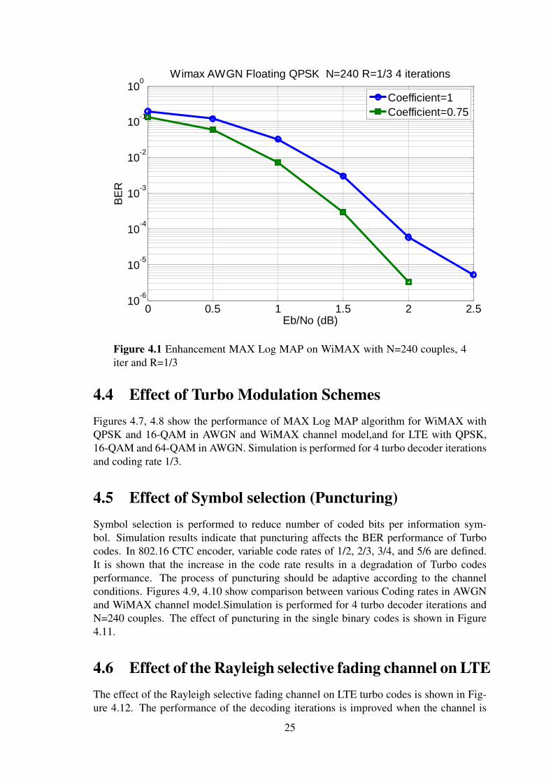
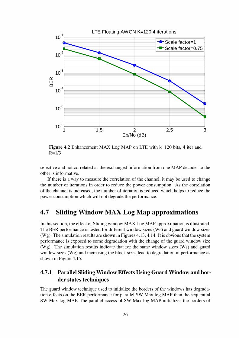
4.1 Enhancement MAX Log MAPFigures 4.1 and 4.2 show that a 0.2 dB improvement is possible for a scaling factor of0.75 compared to a scaling factor of 1 for both LTE and WiMAX with 4 iterations, OPSKscheme, rate 1/3, and in AWGN.
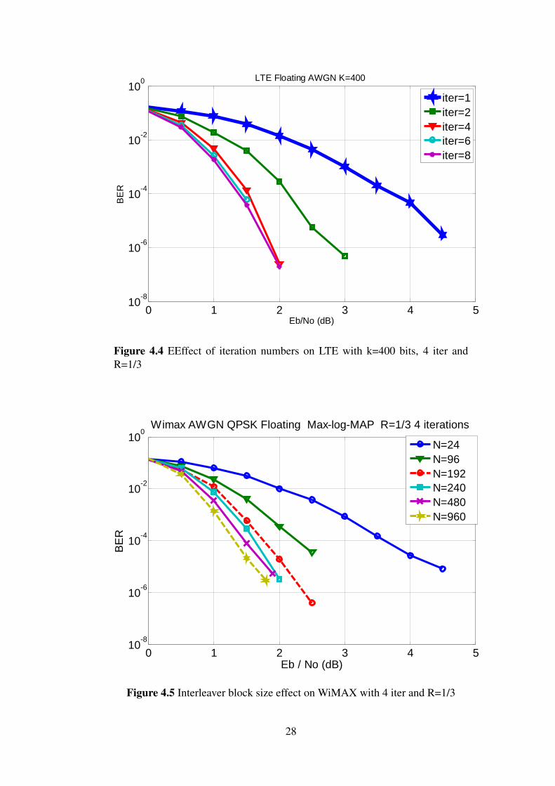
4.2 Effect of number of iterationsAs illustrated earlier, Turbo decoding algorithms are based on iterative decoding. In thiscase, increasing the number of iterations provides an improvement in the original dataestimation. Figures 4.3 and 4.4 illustrate the performance analysis of MAX Log MAPalgorithm for LTE in AWGN and WiMAX in AWGN and the WiMAX channel model.
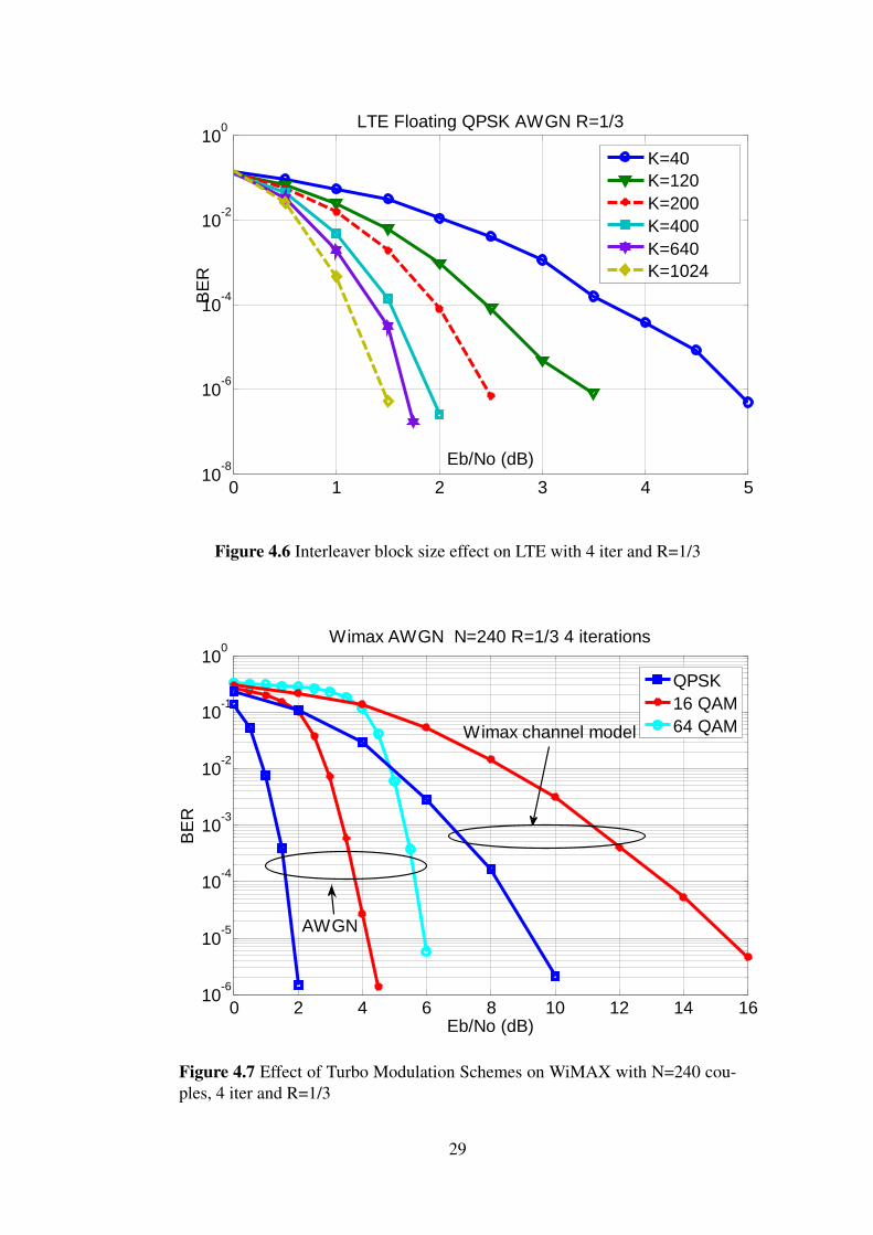
4.3 Effect of Turbo interleaver block sizesSimulation results indicate that Turbo codes performance varies according to the inter-leaver block size. It is shown that the increase of CTC interleaver size enhances the BERperformance for the same SNR. Figures 4.5 and 4.6 illustrate the performance of MAXLog MAP algorithm for WiMAX with interleaver block sizes of 24, 96, 192, 240, 480and 960 couples respectively, and for LTE with interleaver block sizes of 40, 120, 200,400, 480,640 and 1024 bits respectively. Simulation is performed for 4 turbo decoderiterations and coding rate of 1/3 in AWGN.
24
0 0.5 1 1.5 2 2.510
-6
10-5
10-4
10-3
10-2
10-1
100
Eb/No (dB)
BE
R
Wimax AWGN Floating QPSK N=240 R=1/3 4 iterations
Coefficient=1
Coefficient=0.75
Figure 4.1 Enhancement MAX Log MAP on WiMAX with N=240 couples, 4iter and R=1/3
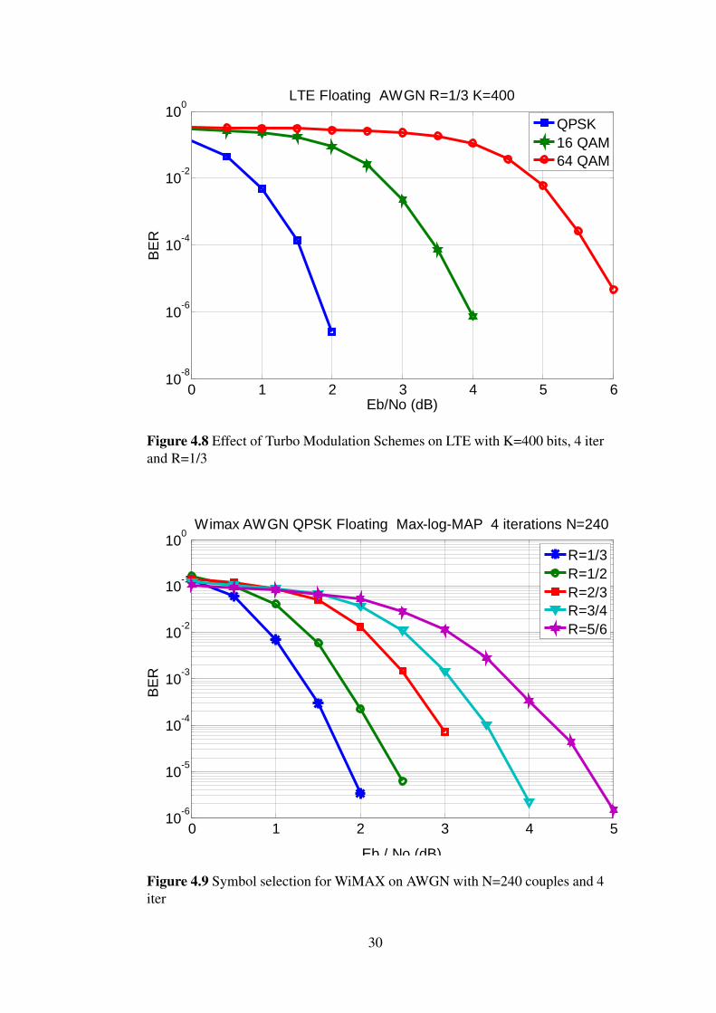
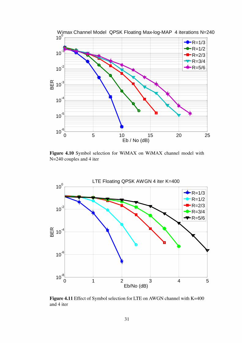
4.4 Effect of Turbo Modulation SchemesFigures 4.7, 4.8 show the performance of MAX Log MAP algorithm for WiMAX withQPSK and 16-QAM in AWGN and WiMAX channel model,and for LTE with QPSK,16-QAM and 64-QAM in AWGN. Simulation is performed for 4 turbo decoder iterationsand coding rate 1/3.
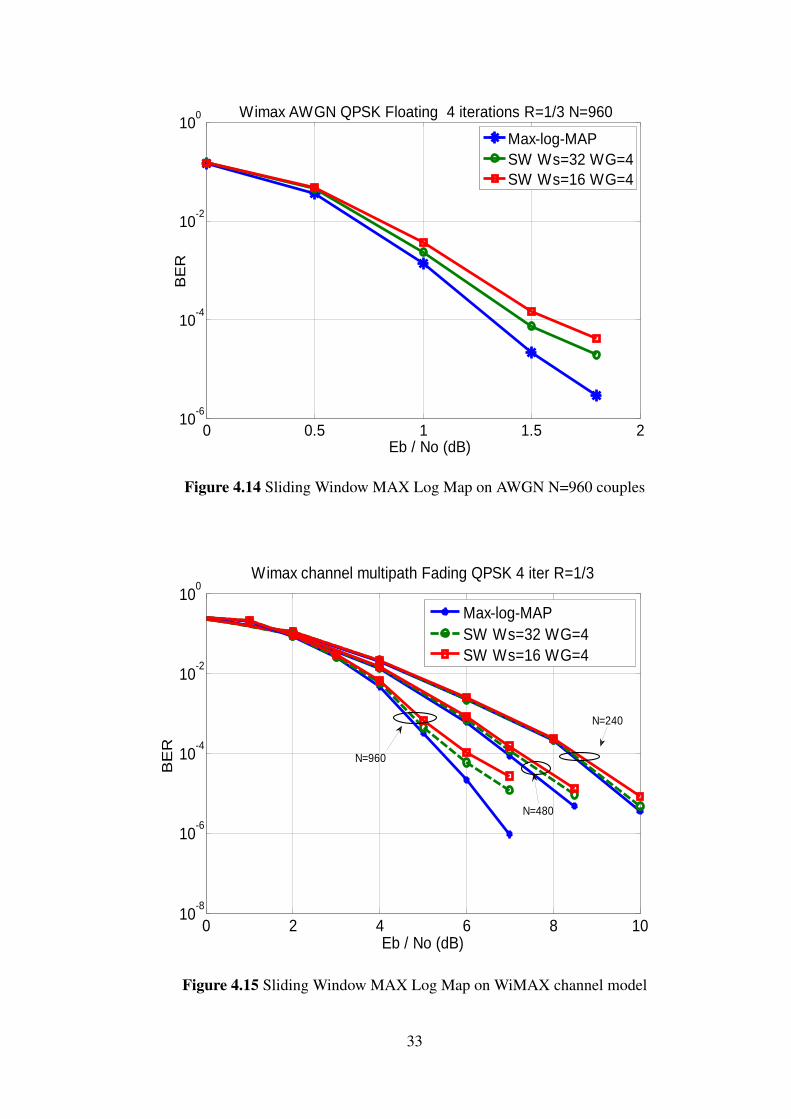
4.5 Effect of Symbol selection (Puncturing)Symbol selection is performed to reduce number of coded bits per information sym-bol. Simulation results indicate that puncturing affects the BER performance of Turbocodes. In 802.16 CTC encoder, variable code rates of 1/2, 2/3, 3/4, and 5/6 are defined.It is shown that the increase in the code rate results in a degradation of Turbo codesperformance. The process of puncturing should be adaptive according to the channelconditions. Figures 4.9, 4.10 show comparison between various Coding rates in AWGNand WiMAX channel model.Simulation is performed for 4 turbo decoder iterations andN=240 couples. The effect of puncturing in the single binary codes is shown in Figure4.11.
4.6 Effect of the Rayleigh selective fading channel on LTEThe effect of the Rayleigh selective fading channel on LTE turbo codes is shown in Fig-ure 4.12. The performance of the decoding iterations is improved when the channel is
25
1 1.5 2 2.5 310
-6
10-5
10-4
10-3
10-2
10-1
LTE Floating AWGN K=120 4 iterations
Eb/No (dB)
BE
R
Scale factor=1
Scale factor=0.75
Figure 4.2 Enhancement MAX Log MAP on LTE with k=120 bits, 4 iter andR=1/3
selective and not correlated as the exchanged information from one MAP decoder to theother is informative.
If there is a way to measure the correlation of the channel, it may be used to changethe number of iterations in order to reduce the power consumption. As the correlationof the channel is increased, the number of iteration is reduced which helps to reduce thepower consumption which will not degrade the performance.
4.7 Sliding Window MAX Log Map approximationsIn this section, the effect of Sliding window MAX Log MAP approximation is illustrated.The BER performance is tested for different window sizes (Ws) and guard window sizes(Wg). The simulation results are shown in Figures 4.13, 4.14. It is obvious that the systemperformance is exposed to some degradation with the change of the guard window size(Wg). The simulation results indicate that for the same window sizes (Ws) and guardwindow sizes (Wg) and increasing the block sizes lead to degradation in performance asshown in Figure 4.15.
4.7.1 Parallel Sliding Window Effects Using Guard Window and bor-der states techniques
The guard window technique used to initialize the borders of the windows has degrada-tion effects on the BER performance for parallel SW Max log MAP than the sequentialSW Max log MAP. The parallel access of SW Max log MAP initializes the borders of
26
0 2 4 6 8 1010
-6
10-5
10-4
10-3
10-2
10-1
100
Wimax QPSK Floating R=1/3 N=240
Eb/No (dB)
BE
R
iter=1
iter=2
iter=4
iter=6
iter=8
AWGN WiMAX Channel
Model
Figure 4.3 EEffect of iteration numbers on WiMAX with N=240 couples, 4 iterand R=1/3
both forward and backward states while the sequential SW Max log MAP initializes thebackward states only.
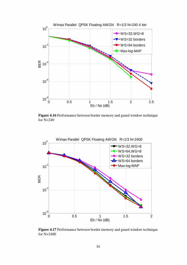
For parallel access, the border memory technique has better performance than theguard window technique as shown in Figures 4.16 and 4.17
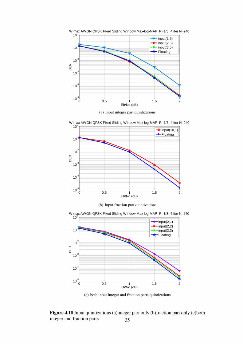
4.8 Fixed point analysisIn this section, fixed point simulation results are presented showing the optimal numberof quantization bits for both input signals and internal signals. The notation < int,q >is used to describe the fixed-point representation, where int represents the bit-width ofinteger part and q represents the bit-width of the fractional part.
In Figures 4.18(a), 4.18(b), and 4.18(c) quantizations of input signals are indicated, itis shown that 2 bits for integer part and 2 bits for fraction part have a good performance,it approaches the performance of the floating point model.
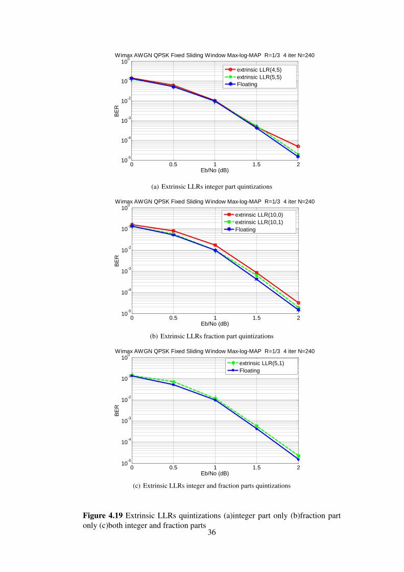
In Figures 4.19(a), 4.19(b), and 4.19(c) quantizations of Extrinsic LLRs signals areindicated, it is shown that 5 bits for integer part and 1 bit for fraction part have a goodperformance, it approaches the performance of the floating point model.Simulation parameters are done with rate 1/3, AWGN channel, Block size N=240 cou-ples, Window size (Ws)=32, guard window (Wg)=4 and with 4 iterations.
27
0 1 2 3 4 510
-8
10-6
10-4
10-2
100 LTE Floating AWGN K=400
Eb/No (dB)
BE
R
iter=1
iter=2
iter=4
iter=6
iter=8
Figure 4.4 EEffect of iteration numbers on LTE with k=400 bits, 4 iter andR=1/3
(c) Extrinsic LLRs integer and fraction parts quintizations
Figure 4.19 Extrinsic LLRs quintizations (a)integer part only (b)fraction partonly (c)both integer and fraction parts
36
Chapter 5
Memory Conflict Analysis
The parallel sliding window decoding leads to contention on memory due to parallelaccess, which causes latency and reduces the throughput. The conversion from radix-2single binary turbo codes to radix-4 single binary turbo codes adds more conflicts as thetime to write the whole data block is reduced by half.
5.1 Maximum Contention Free InterleaversThere are two types of interleavers, unconstrained interleavers and constrained inter-leavers. The constrained interleavers are maximum contention free (MCF) [12] whichmean no conflicts happen due to parallel accesses as shown in Figure 5.1. But the MCFinterleavers require that K =M∗P∗W where K is the block length, W is the window size,P is the number of parallel windows and M is an integer as shown in Figure 5.2. Hence,the Window size W and the number of parallel windows P must be variables based on theblock length K.
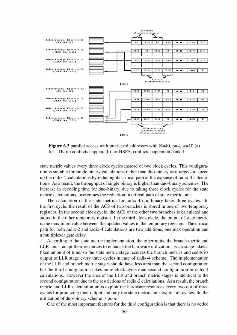
There are few standards that include contention-free interleavers such as WiMAXand 3GPP-LTE. Conversely, in parallel radix-4 scheme, 3GPP-LTE and WiMAX are notMCF, which means that they will face conflicts during parallel access. However, by usingthe even-odd memory scheme those conflicts can be avoided.
Figure 5.2 An example for collisions happen for WiMAX interleaver whenM=0.96
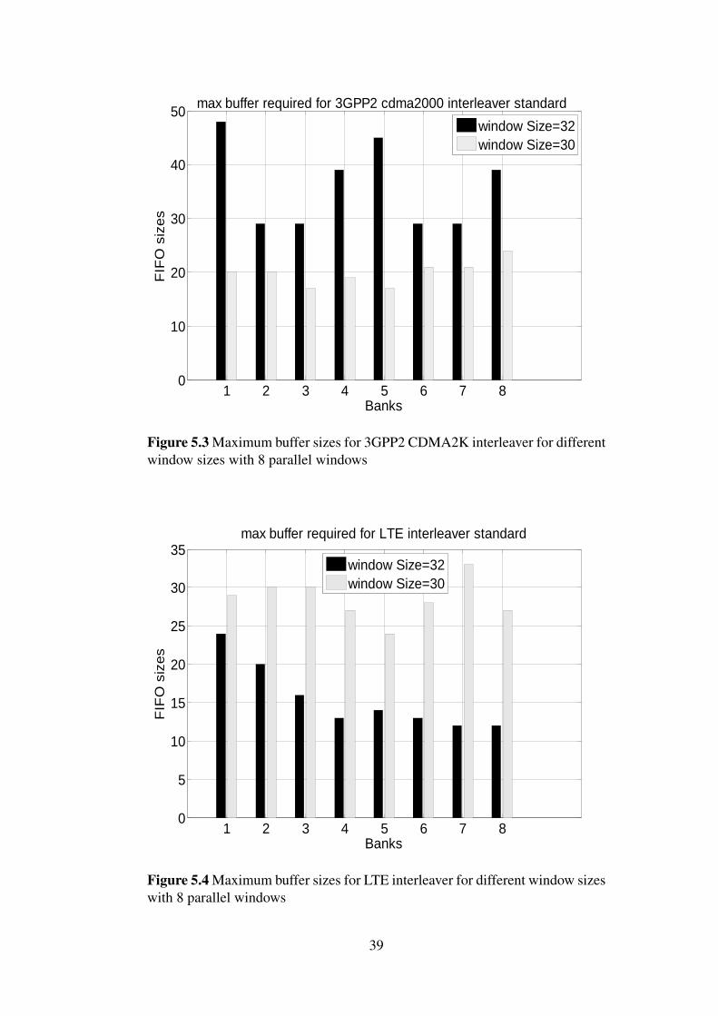
5.2 Effect of Window Size on Memory ContentionsBuffering of the conflicting data until processed by the targeted memory, was proposedto avoid memory contentions. Computer simulations are done on Matlab to determinethe buffer sizes for different interleaver patterns that are used in different standards.
Selecting the window size is an important step for reducing the size of the bufferstructure as shown in Figure 5.3 and 5.4. However this leads to complexity in calculatingthe offset and bank number for memory addressing which require dividers. The areaof the dividers is very large, and long time is needed for calculations. To avoid thosedrawbacks, the window size should be power of 2.
The second decoder cannot start its decoding process until the first decoder finisheswriting the all values to memory. This latency is varying from standard to standard anddepends on block sizes as shown in Figure 5.5. This feature makes the scheme not suit-able for constrained real time systems.
5.3 The Second Scheme of Parallel Decoding Analysis
5.3.1 Decreasing the Number of ConflictsAccording to the timing sequence of the parallel decoding algorithm 3.9, where eachSISO decoder generates two extrinsic LLRs per clock cycle. As shown in Figure 5.6,delay buffers can be used to store one of the two LLRs which are generated by eachSISO to reduce the memory conflicts and area. However, additional latency is producedbecause the decoder cannot start its process until the other decoder finishes all its writingoperations. Although delay buffers are added the total buffer size is reduced since thetotal line buffers are reduced which have bigger width than the added delay buffers. Manycomparisons have been done to select the efficient hardware and system requirements.
In this analysis, we assume that the memory runs at double the clock frequency of thesystem. The double speed of the memory clock has many benefits:
• Reduces the number of conflicts which decreases the number of buffers required tostore the conflict data.
38
1 2 3 4 5 6 7 80
10
20
30
40
50
Banks
FIF
O s
ize
s
max buffer required for 3GPP2 cdma2000 interleaver standard
window Size=32
window Size=30
Figure 5.3 Maximum buffer sizes for 3GPP2 CDMA2K interleaver for differentwindow sizes with 8 parallel windows
1 2 3 4 5 6 7 80
5
10
15
20
25
30
35
Banks
FIF
O s
ize
s
max buffer required for LTE interleaver standard
window Size=32
window Size=30
Figure 5.4 Maximum buffer sizes for LTE interleaver for different window sizeswith 8 parallel windows
39
1 2 3 4 5 6 7 80
5
10
15
20
Banks
La
ten
cy (
nu
mb
er
of
clo
cks)
max Latency required during half iters for 3GPP2 cdma2000 interleaver standard
window Size=32
window Size=30
Figure 5.5 Maximum latency for 3GPP2 CDMA2K interleaver for differentwindow sizes with 8 parallel windows
Bank
2
Bank
p
Bank
1
SISO
2
SISO
p
SISO
1
Bank
2
Bank
p
Bank
1
Dat
a Al
ignm
ent
Bank
2
Bank
p
Bank
1
.
Interleaved/Deinterleaved Addresses
Memory
Ext. LLR 1
LLR
1
Delayed Buffers
LLR
2
LLR
p
Ext. LLR 2
Figure 5.6 Parallel architecture with adding delayed buffers to reduce the num-ber of concurrent values need to write by half at every clock
40
• Avoids variable latency. Variable latency is unsuitable for real time communica-tions systems, through fast writing of the stored data.
• Reduces latency in case of adding delay buffer when two decoders exchange theinformation between them.
The use of two clocks in the design, one for the system and another for the memory, addsto the design complexity.
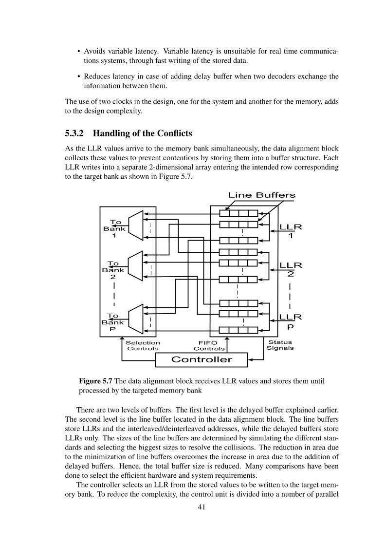
5.3.2 Handling of the ConflictsAs the LLR values arrive to the memory bank simultaneously, the data alignment blockcollects these values to prevent contentions by storing them into a buffer structure. EachLLR writes into a separate 2-dimensional array entering the intended row correspondingto the target bank as shown in Figure 5.7.
LLR
1
To
Bank
1
Controller
FIFO
Controls
Selection
Controls
Status
Signals
Line Buffers
To
Bank
2
To
Bank
P
LLR
2
LLR
p
Figure 5.7 The data alignment block receives LLR values and stores them untilprocessed by the targeted memory bank
There are two levels of buffers. The first level is the delayed buffer explained earlier.The second level is the line buffer located in the data alignment block. The line buffersstore LLRs and the interleaved/deinterleaved addresses, while the delayed buffers storeLLRs only. The sizes of the line buffers are determined by simulating the different stan-dards and selecting the biggest sizes to resolve the collisions. The reduction in area dueto the minimization of line buffers overcomes the increase in area due to the addition ofdelayed buffers. Hence, the total buffer size is reduced. Many comparisons have beendone to select the efficient hardware and system requirements.
The controller selects an LLR from the stored values to be written to the target mem-ory bank. To reduce the complexity, the control unit is divided into a number of parallel
41
units, p. Each unit consists of two selectors and two row enablers connected as shownin Figure 5.8. The “selector from low” takes the request, status signal, number 1 as thehighest priority, and request number n, representing the number of concurrent LLRs, asthe lowest priority. The “selector from high” takes the request number n as the high-est priority, and request number 1 as the lowest priority. The “row enabler 1” is activewhen one or more requests are asserted. The “row enabler 2” is active when two or morerequests are asserted.
Selector
From low
Selector
From
High
Row
Enabler
1
Row
Enabler
2
Status
Signals
Selection access 1
Selection access 2
R1
Rp
Bank 1
Controller
Bank p
Controller
Figure 5.8 The controller of the data alignment block with divided into p smallcontrollers
In this design, the used memories are dual port memories, which allow two concurrentmemory accesses per clock cycle. Many requests may arrive simultaneously to access oneof the memory banks. To determine which one or two requests will be served, a simplemechanism is applied separately for each memory bank. The upper selector scans fromlow to high, and selects the minimum active request index. The lower selector scans fromhigh to low, and selects the maximum active request index. Then the two selected indicesare enabled to be written to the memory bank. The outputs of the row enabler representread enables of buffers and the outputs of the selectors represent control selections forthe multiplexers for each bank.
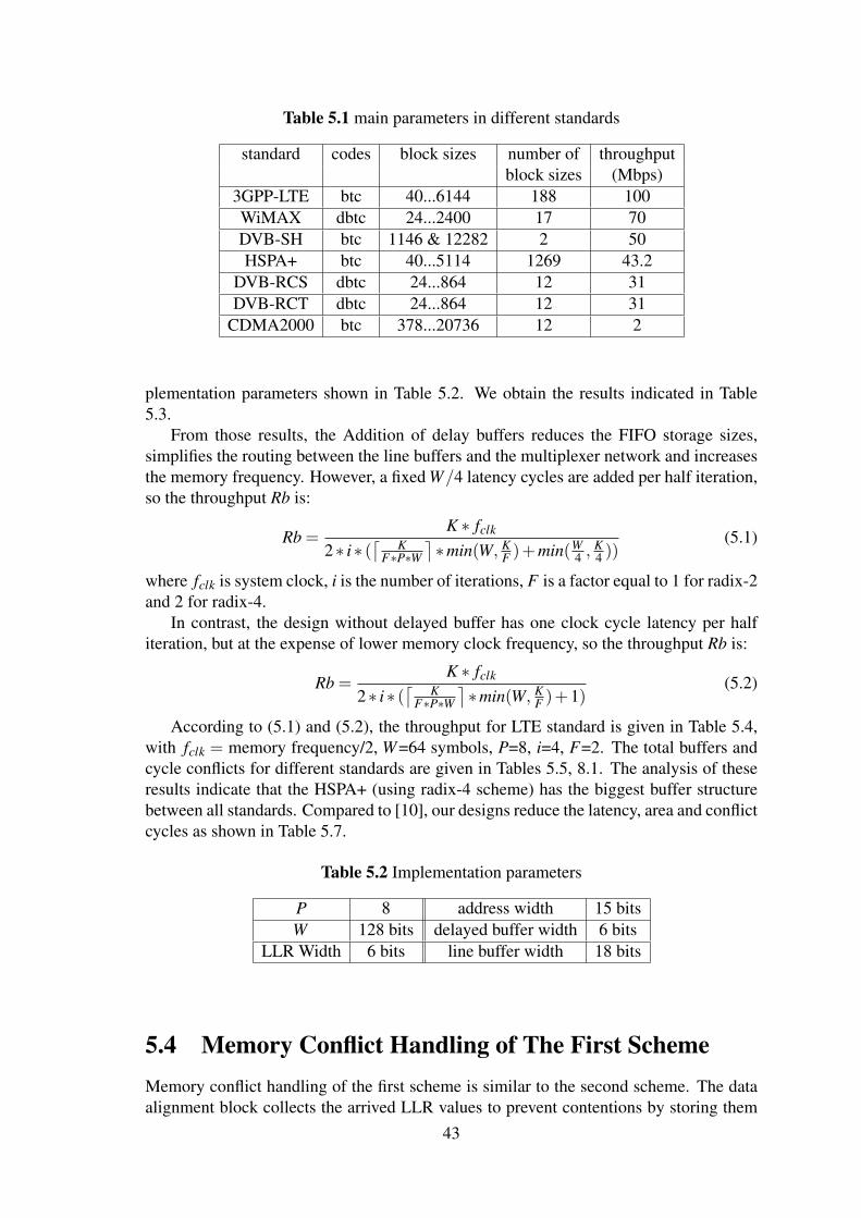
5.3.3 Simulations Results for Memory ConflictTable 5.1 summarizes the turbo codes used in different standards. Each standard has itsown parameters such as the used code types, the possible block lengths and maximumthroughput requirement. The permutation law in WiMAX, DVB-RCS and DVB-RCTis the same. Similarly, it is the same in CDMA2000 and DVB-SH. The implementeddata alignment block is synthesized on Altera Stratix-III EP3SC150 FPGA with the im-
42
Table 5.1 main parameters in different standards
standard codes block sizes number of throughputblock sizes (Mbps)
plementation parameters shown in Table 5.2. We obtain the results indicated in Table5.3.
From those results, the Addition of delay buffers reduces the FIFO storage sizes,simplifies the routing between the line buffers and the multiplexer network and increasesthe memory frequency. However, a fixed W/4 latency cycles are added per half iteration,so the throughput Rb is:
Rb =K ∗ fclk
2∗ i∗ (⌈ K
F∗P∗W⌉∗min(W, K
F )+min(W4 ,
K4 ))
(5.1)
where fclk is system clock, i is the number of iterations, F is a factor equal to 1 for radix-2and 2 for radix-4.
In contrast, the design without delayed buffer has one clock cycle latency per halfiteration, but at the expense of lower memory clock frequency, so the throughput Rb is:
Rb =K ∗ fclk
2∗ i∗ (⌈ K
F∗P∗W⌉∗min(W, K
F )+1)(5.2)
According to (5.1) and (5.2), the throughput for LTE standard is given in Table 5.4,with fclk = memory frequency/2, W=64 symbols, P=8, i=4, F=2. The total buffers andcycle conflicts for different standards are given in Tables 5.5, 8.1. The analysis of theseresults indicate that the HSPA+ (using radix-4 scheme) has the biggest buffer structurebetween all standards. Compared to [10], our designs reduce the latency, area and conflictcycles as shown in Table 5.7.
5.4 Memory Conflict Handling of The First SchemeMemory conflict handling of the first scheme is similar to the second scheme. The dataalignment block collects the arrived LLR values to prevent contentions by storing them
43
Table 5.3 Comparison between two designs for data alignment block
parameter without delayed with delayedbuffer buffer
Number of line buffers 610 228Number of delayed buffers 0 256
Total FIFO size (bits) 10980 5640Number of logic cells 2064 856
Max. memory frequency(MHz) 231.48 294.9Latency per half-iteration 1 16
(clock cycles)
Table 5.4 Throughput comparison between two designs for LTE standard
Block length(bits) without delayed buffer with delayed buffer40(min length) 27.5571Mbps 29.49Mbps
6144(max length) 231.48Mbps 283.104Mbps
Table 5.5 Memory analysis for radix-2 implementations (all block sizes for eachstandard)
standard cycle conflicts total buffers (bits)with buffers no buffers with buffers no buffers
Table 5.7 Comparison of memory conflict for HSPA+ (Radix-4 scheme) with 2parallel SISOs
parameter without delayed with delayed [10]buffer buffer
Extra Fifo Cycles 1 16 65Conflicting Cycles(K=5114) 813 273 1037
Total Fifo Size 48 94 367
44
into a buffer structure. The design of the data alignment block is identical for the secondscheme as shown in Figure 5.7. As the first scheme allows each SISO to write one LLRper clock cycle, there is no need to use double clock frequency for the memory. The sameclock for memory and the system simplifies the design. As a result, the controller insidethe data alignment block is changed to select one of the stored data in the line buffers foreach bank as shown in Figure 5.9.
Selector
From low
Row
Enabler
1
Status
Signals
Selection access
R1
Rp
Bank 1
Controller
Bank p
Controller
Figure 5.9 The controller of the data alignment block with divided into p smallcontrollers
In this scheme, the used memories are single port memories to simplify the designand to reduce the power and the area of the design. So one memory access per clockcycle will be allowable for each bank. The first scheme is our timing sequence which isused in the proposed ASIP processor.
45
Chapter 6
ASIP Architecture
6.1 ASIP ArchitectureASIP architecture combines configurable and dedicated units through targeting certainapplications. The increase of the proportion of the configurable units in the design resultsin more flexibility but, at the same time, it has a bad impact on the decoding throughput.So, the choice of the suitable architecture for the ASIP plays a significant role to meet theimplementation requirements for different turbo decoder types.
The parallelism in turbo process is required to achieve the high throughput demand.There are two approaches to achieve the parallelism on the ASIP architecture. The firstapproach is to build an ASIP processor including multiple SISOs and each SISO pro-cesses independent Windows. The interfacing between multi-SISOs is controlled by theinstructions of the processor. Such mechanism is fully optimized for turbo decoder ar-chitecture and avoids the waste cycles during exchanging the data [20]. The secondapproach is multiple ASIPs and the interfacing between them is done through communi-cation routers to send and to receive the required data in packets format which is callednetwork on chips (NOC) [22] [24]. The second approach produces complex interfacesand adds additional latency for the decoding time.
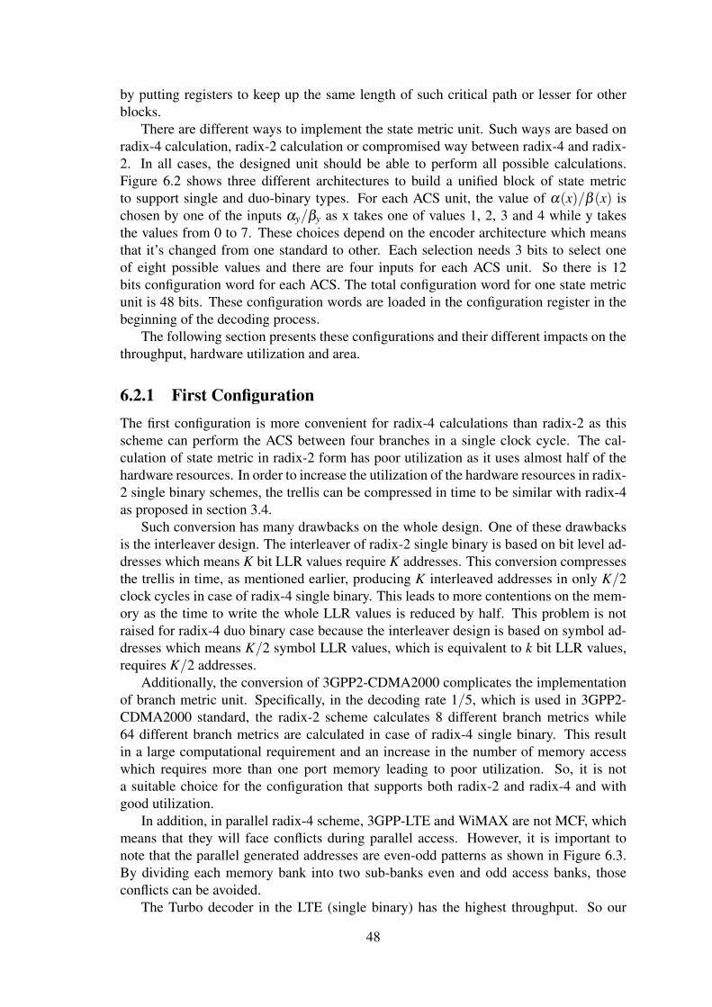
A pipelined processor is designed to reduce the critical path to produce high through-put. The architecture consists of nine stages: fetch, decode and execution stages as shownin Figure 6.1. The execution stages include seven stages: addresses generation, branchmetric calculations, state metric calculations, three stages for LLR calculations and writeback stage.
6.2 State Metric UnitThe state metric units occupy most of the design area which is around two-thirds ofthe hardware resources. Both forward and backward state metric values are requiredfor calculating the LLR values. The implementation of the forward and backward statemetric units is identical. To meet the throughput requirement two units are implemented,one for forward metric and the other for the backward metric, to work simultaneously.The add compare select, ACS, is the basic calculation unit for the state metric units. Thefeedback in the state metric unit, due to recursion, imposes certain critical path whichhas a big influence on the throughput. The critical path of the state metric unit, in thiscase represents the dominant critical path, determines how to design the pipelined stages
46
Program
Memory
SPC1SPC2SPC3
Sta
ck
Ca
ll_P
C
EPC1
EPC2
EPC3
PC
+ +
1
+
IR[6:0]
Jump and
Nested Loop
controller
FEIR
Instru
ctio
n
De
co
de
r
DC
Pipelined
SISO 1
Pipelined
SISO 2
Pipelined
SISO P
ExEC
Channel
data
Memory
LLR
Memory
1
LLR
Memory
2
Forward
Branch
Metric Unit
Backward
Branch
Metric Unit
Forward
State
Metric Unit
Backward
State
Metric Unit
3-stage
LLR
pipelined
Da
ta A
lig
nm
en
t B
lock
Two Forward
Border State
Memories
Two
Backward
Border State
Memories
Ba
ckw
ard
Sta
te M
em
ory
in
out
out in F_A
B_A
I1 I2
I1 I2
Figure 6.1 Block diagram for pipelined ASIP architecture showing the differentstages
47
by putting registers to keep up the same length of such critical path or lesser for otherblocks.
There are different ways to implement the state metric unit. Such ways are based onradix-4 calculation, radix-2 calculation or compromised way between radix-4 and radix-2. In all cases, the designed unit should be able to perform all possible calculations.Figure 6.2 shows three different architectures to build a unified block of state metricto support single and duo-binary types. For each ACS unit, the value of α(x)/β (x) ischosen by one of the inputs αy/βy as x takes one of values 1, 2, 3 and 4 while y takesthe values from 0 to 7. These choices depend on the encoder architecture which meansthat it’s changed from one standard to other. Each selection needs 3 bits to select oneof eight possible values and there are four inputs for each ACS unit. So there is 12bits configuration word for each ACS. The total configuration word for one state metricunit is 48 bits. These configuration words are loaded in the configuration register in thebeginning of the decoding process.
The following section presents these configurations and their different impacts on thethroughput, hardware utilization and area.
6.2.1 First ConfigurationThe first configuration is more convenient for radix-4 calculations than radix-2 as thisscheme can perform the ACS between four branches in a single clock cycle. The cal-culation of state metric in radix-2 form has poor utilization as it uses almost half of thehardware resources. In order to increase the utilization of the hardware resources in radix-2 single binary schemes, the trellis can be compressed in time to be similar with radix-4as proposed in section 3.4.
Such conversion has many drawbacks on the whole design. One of these drawbacksis the interleaver design. The interleaver of radix-2 single binary is based on bit level ad-dresses which means K bit LLR values require K addresses. This conversion compressesthe trellis in time, as mentioned earlier, producing K interleaved addresses in only K/2clock cycles in case of radix-4 single binary. This leads to more contentions on the mem-ory as the time to write the whole LLR values is reduced by half. This problem is notraised for radix-4 duo binary case because the interleaver design is based on symbol ad-dresses which means K/2 symbol LLR values, which is equivalent to k bit LLR values,requires K/2 addresses.
Additionally, the conversion of 3GPP2-CDMA2000 complicates the implementationof branch metric unit. Specifically, in the decoding rate 1/5, which is used in 3GPP2-CDMA2000 standard, the radix-2 scheme calculates 8 different branch metrics while64 different branch metrics are calculated in case of radix-4 single binary. This resultin a large computational requirement and an increase in the number of memory accesswhich requires more than one port memory leading to poor utilization. So, it is nota suitable choice for the configuration that supports both radix-2 and radix-4 and withgood utilization.
In addition, in parallel radix-4 scheme, 3GPP-LTE and WiMAX are not MCF, whichmeans that they will face conflicts during parallel access. However, it is important tonote that the parallel generated addresses are even-odd patterns as shown in Figure 6.3.By dividing each memory bank into two sub-banks even and odd access banks, thoseconflicts can be avoided.
The Turbo decoder in the LTE (single binary) has the highest throughput. So our
48
ACS0
ACS1
ACS6
ACS7
-
+
(2)
(1) / (1)
+
(1)
(2) / (2)
(0) / (0) -
-
1
0
0
1
S0
S0
R1
R2
-
+
(2)
(1) / (1)
+
(1)
(2) / (2)
(0) / (0) -
-
TMP
-
-
+
(2)
(1) / (1)
+
(1)
(2) / (2) (0) / (0)
-
+
(4)
(3) / (3)
+
(3)
(4) / (4)
-
-
First
Configuration
Second
Configuration
Third
Configuration
0 0/
1 1/
7 7/
0 0( ) / ( )nxt nxt
1 1( ) / ( )nxt nxt
7 7( ) / ( )nxt nxt
6 6( ) / ( )nxt nxt
ACS
Unit
State Metric Unit
(1) / (1)
(4 ) / (4 )
(2) / (2)
0 0/
1 1/
7 7/
Configuration
Register
Figure 6.2 State Metric Unit
target is to speed the decoding process for single binary to achieve this requirement.
6.2.2 Second ConfigurationThe second configuration is based on radix-2 calculations as this scheme performs theACS between two branches in a single clock cycle. An iterative manner is used for radix-4 calculations which produce the state metric values every two clock cycles. This schemeis suitable for all turbo code standards with good utilization for hardware resources. Theavoidance of the trellis compression technique leads to less conflict, less area and lesscomplexity in the interleaver design. The same throughput is achieved for single binaryand duo-binary schemes.
The calculation of the state metrics for radix-4 duo-binary, ACS between four branches,takes two cycles. In the first cycle, the result of the ACS of two branches is stored in atemporary register. At the second clock cycle, the ACS of the other two branches is cal-culated, and then the output of state metric is the maximum value between the updatedvalue and the stored value in a temporary register. The critical path for radix-2 includestwo additions, one max operation and a multiplexer gate delay. On the other side, thecritical path for radix-4 includes two additions, two max operations and a multiplexergate delay.
6.2.3 Third ConfigurationThe third configuration is based on radix-2 calculations similar to the second configura-tion. In the same way, an iterative manner is used for radix-4 calculations but produce the
49
0 1913 6 24 37
30 93 36 14 27
20 3933 26 4 17
10 2923 16 34 7
Memory Bank 0
(0 to 9)
Memory Bank 1
(10 to 19)
Memory Bank 2
(20 to 29)
Memory Bank 3
(30 to 39)
Even
Addresses
Odd
Addresses
39 925 17 11 5
34 1026 20 14 6
36 1228 18 13 3
32 824 16 15 7
Memory Bank 0
(0 to 9)
Memory Bank 1
(10 to 19)
Memory Bank 2
(20 to 29)
Memory Bank 3
(30 to 39)
Random
Even-Odd
Addresses
(a)
(b)
Figure 6.3 parallel access with interleaed addresses with K=40, p=4, w=10 (a)for LTE, no conflicts happen, (b) for HSPA, conflicts happen on bank 4
state metric values every three clock cycles instead of two clock cycles. This configura-tion is suitable for single binary calculations rather than duo-binary as it targets to speedup the radix-2 calculations by reducing its critical path at the expense of radix-4 calcula-tions. As a result, the throughput of single binary is higher than duo-binary schemes. Theincrease in decoding time for duo-binary, due to taking three clock cycles for the statemetric calculations, overcomes the reduction in critical path of state metric unit.
The calculation of the state metrics for radix-4 duo-binary takes three cycles. Inthe first cycle, the result of the ACS of two branches is stored in one of two temporaryregisters. In the second clock cycle, the ACS of the other two branches is calculated andstored in the other temporary register. In the third clock cycle, the output of state metricis the maximum value between the updated values in the temporary registers. The criticalpath for both radix-2 and radix-4 calculations are two additions, one max operation anda multiplexer gate delay.
According to the state metric implementation, the other units, the branch metric andLLR units, adapt their resources to enhance the hardware utilization. Each stage takes afixed amount of time, so the state metric stage receives the branch metrics and sends itsoutput to LLR stage every three cycles in case of radix-4 scheme. The implementationof the LLR and branch metric stages should have less area than the second configurationbut the third configuration takes more clock cycle than second configuration in radix-4calculations. However the area of the LLR and branch metric stages is identical to thesecond configuration due to the restrictions of radix-2 calculations. As a result, the branchmetric and LLR calculation units exploit the hardware resources every two out of threecycles for producing their output and only the state metric units exploit all cycles. So theutilization of duo-binary scheme is poor.
One of the most important features for the third configuration is that there is no added
50
latency cycles between the two decoders because of the conflicts on memory banks asshown in Figure 6.4. However, there are some instructions should be executed to ini-tialize the operation of each MAP decoder when transferring from one MAP decoder tothe other. Hence, there is no benefit from zero latency cycles. The zero latency cyclesare suitable for dedicated architectures where the two MAP decoders are consecutivelyworking without initialization.
Figures in 6.4, 6.5, and 6.6 show the effects of the parallel architecture of the threeconfigurations on added latency between two decoders, memory buffers, and the proba-bilities of simultaneous accesses on memory banks. In addition, the different configura-tions are synthesized on Altera stratix-III FPGA and the results are given in Table 6.1.The table results are in case of one SISO implementation and the parallel SISOs effectsare not included.
From those results, the first configuration has the highest throughput with adequatearea in case one SISO implementation for both turbo code types. So, the first configura-tion is the best choice for the one SISO implementation. However, large latency is addedfor first configuration in case of the parallel architecture, as shown in Figure 6.4, becauseof the extra clock cycles required to resolve the memory conflicts. A large degradation ofthe throughput and large buffers are the result in case of using more than one SISO. As aresult, such configuration should be avoided in the parallel architecture scheme.
Additionally, the third configuration has the least conflicts, the smallest area and theleast number of buffers among the different configurations. In addition, the third config-uration has the highest throughput per area in case of single binary scheme. However,the third configuration has the least throughput among the different configurations forduo-binary scheme.
The second configuration has an acceptable latency between the two decoders, andalso not much buffers are needed to resolve the memory conflicts. The second configura-tion gives almost the same high throughput for both turbo code types with adequate area.The second configuration is the suitable choice amongst these configurations for parallelarchitecture design.
Table 6.1 Comparison of Three Configuration for one SISO
First Second ThirdComparison Config. Config. Config.
Max. clock frequency 125.27MHz 125.27MHz 140.88MHzThroughput for Radix-2
LTE @6144 bit 30.8Mbps 15.5Mbps 17.4MbpsThroughput for Radix-4WiMAX @2400 symbol 30.1Mbps 15.2Mbps 10.17Mbps
State Metric unit 1844 LC 1035 LC 946 LCLLR calculation unit 1948 LC 918 LC 918 LCBranch Metric Unit 126 LC 160 LC 160 LC
One SISO unit 5888 LC 3308 LC 3130 LC
The initialization of the forward and backward states border is chosen by
• all zeros, equal probabilities for all the states, which happens at the first iterationfor each MAP decoder
51
0 1000 2000 3000 4000 50000
10
20
30
40
50
60HSPA radix-4 latency due to conflicts on memory banks with 16 parallel SISOs
Block Sizes
Late
ncy C
ycle
s
First Configuration
Second Configuration
Third Configuration
Figure 6.4 Effect of three configurations on latency between the 2 decoders dueto memory conflicts with W=64, P=16, for some block sizes of HSPA+ standard
0 2 4 6 8 10 12 14 160
100
200
300
400
500
600HSPA radix-4 buffer sizes for all block sizes with 16 parallel SISOs
Banks
Num
ber
of
Buff
ers
First Configuration
Second Configuration
Third Configuration
Figure 6.5 Effect of three configurations on memory buffers in the data align-ment block with W=64, P=16, for all block sizes of HSPA+ standard
52
0 2 4 6 8 10 12 14 160
5
10
15
20
25
30
35
HSPA radix-4 conflicts ratios on memory banks for all block sizes
with 16 parallel SISOs
Number of Simultaneous Memory Bank Access
Mem
ory
Conflic
t P
robability %
First Configuration
Second Configuration
Third Configuration
Figure 6.6 Effect of three configurations on probability of simultenous accesseson memory banks with W=64, P=16, for all block sizes of HSPA+ standard
• border values which happens at the iterations followed by the first one
• starting from the state zero S0 or
• with the updated values for recursive operation which happens within the windowcalculations.
Where the starting from the state zero S0 means giving the highest value to S0 andthe lowest values to the other states.
6.3 Memory AccessTo enable the processor to work in a faster manner, dedicated memories are needed tostore and retrieve the manipulated data. In addition, dedicated calculation units for gen-erating the required addresses and control signals are also needed. All these dedicatedunits are controlled by the instructions of the program.
Each MAP decoder for the single binary scheme has one received systematic symboland one received parity symbol. On the other hand, each MAP decoder for duo-binaryscheme has two received systematic symbols and two received parity symbols. The de-sign of memory should be implemented to adapt with two types of turbo codes. The ar-chitecture of proposed memory consists of two sub-memories. These two sub-memoriesoperate as two separate units in case of duo-binary and one unit in case of single binary.
There is another potential problem for the memory design: each branch metric unitmay read two different values from each memory. To avoid the usage of dual port memo-ries, the memory is divided into a number of memory banks and the size of each memory
53
bank is W as shown in the Figure 6.7(a). According to the decoding process, the first readvalue from top to down of a certain bank goes to forward branch metric unit as shownin the Figure 6.7(b). While the second read from down to top of the next bank goes tobackward branch metric unit. So the offset part of the address that accesses the forwardbank is inverted to access the backward bank.
In addition, the LLR memory works in two modes Duo-binary and single binarymodes. For single binary mode only one LLR value (LLR1) is stored while for duo-binarythere are three LLR values (LLRA, LLRB and LLRC) to be stored. The maximum lengthof memory for single binary is around 6,500 while for duo-binary is 2400. To maximizethe utilization of this block, the memory of LLRA and LLRB units as one block in singlebinary mode where LLRA memory is used for LLR1 even addresses and LLRB memoryis used for LLR1 odd addresses. The memories of LLRA and LLRB units work as twosub blocks in duo-binary mode. The memory of LLRC values isn’t used in single binarymode.
There are two memories to store the interleaver/deinterleaved addresses. These mem-ories provide the addresses to the data alignment block to store the LLR data. Manyworks has used a loadable interleaver mechanism such as in [21]. All these memo-ries are work in sequential manner, so each memory has its address counter to point tothe current location. The enable signals of these addresses counters are come from theinstructions of the processor.
6.4 Branch Metric UnitThe number of branch metrics changes from one standard to another according to thetype of turbo codes and the coding rate. Most of the current standards have eight states.Each state in the trellis diagram has four possible branches for duo-binary scheme, wherethe possible combinations belong to 00, 10, 01 and 11, so there are thirty-two possiblebranches. However the number of calculations of the branch metric is reduced by half,as there are sixteen different values and the others are the same. In the same manner,each state in the single binary scheme has two possible branches, where the possiblecombinations belong to 0 and 1, so there are sixteen possible branches. However thenumber of calculations of the branch metrics is reduced to be four branch metrics forLTE standard and eight branch metrics for UMTS.
The proposed branch metric unit is configured to generate sixteen, eight and fourbranch metrics as shown in Figure 6.8. The output of the branch metric unit goes to thestate metric and LLR units. As explained earlier, the calculation of the state metrics andLLR values take two clock cycles for duo-binary and one clock cycle for single binaryschemes. The proposed branch metric unit produces eight branch metrics every one clockcycle. The branch metric calculations of the WiMAX standard take two phases. In thefirst phase, the branch metric unit produces the first eight branch metrics which belongto the pair of inputs 00 and 01. In the second phase, the branch metric unit producesthe other eight branch metrics which belong to the pair of inputs 10 and 11. The branchmetric calculations are done in one clock cycle in case of LTE scheme. For UMTScalculations, the upper four branch metrics are identical to the lower branch metrics whichsimplify the design of the state metric.
54
Memory RA/RB
Memory RY/RW
Memory interleaved RA/RB
Memory interleaved RY/RW
Memory RA
Memory RB
Data_in
R_F
WE1
The rest of Address Bank Select Offset
WE1
WE2
Write Control
+1
0 10 1
A1A2
A1
RA_F
RA_B
RB_F
RB_B
D_inAddr
D_in
Addr D_out
WE
Single port
Memory
WE2
A2
D_in
Addr D_out
WE
Single port
Memory
WEn
A2
D_in
Addr D_out
WE
Single port
Memory
R_B
Address
Decoder
Enable
WEn
-
Addr
A2
A1 63 62 2 1 0 0 1 2 63 63 62
0 1 62 63 6361 62 61 0 0 1
clk
(a)
(b)
Figure 6.7 Block diagram for channel data memory
55
+
+
+
0
+RA
RY RW
+
+
RA
RB
RY
3
1
0
2
0
+
RA
0
6
5
4
7
-
+ +
RA RB
+
+
+
+
+
+
+
( 01)
in t(11)
in t
( 01)
in t(10 )
int
(10 )
int
(10 )
int
Figure 6.8 Branch Metric Unit
6.5 LLR Calculation UnitThe turbo decoder algorithm estimates the final decision of the received data based onthe LLR values at the end of the pre-determined iterations. The calculation of the LLRvalues requires branch metrics as well as forward and backward state metrics. Accordingto the proposed decoding process, the backward state metrics of a window are calculatedin advance of the forward state calculations which results in the production of the LLRvalues to be delayed within the first W cycles. Then, the LLRs values are concurrentlyproduced from the SISOs units and are transmitted to the LLRs memories.
The LLR calculation unit is divided into three pipelined stages in order to enhancethe allowable maximum frequency as shown in Figure6.9. These stages are two 2-stageLLR calculation units and another stage is added for duo-binary calculation as shown inFigure 6.1. Each 2-stage LLR calculation unit produces one LLR value.
As mentioned earlier, the duo-binary scheme requires producing four LLR valueswhich represent the probability of the received symbol to be one of 00, 10, 01 or 11. TheLLR calculations of the duo-binary scheme take two phases. At the first phase, the LLRvalues of Λ
(00)int and Λ
(01)int are calculated and the difference between them, Λ
(01)ext , is sent
to the memory. In addition, the Λ(00)int is stored to be used in the next clock cycle. At
the second phase, the LLR values of Λ(10)int and Λ
(11)int are calculated and subtracted from
the Λ(00)int to produce Λ
(10)ext and Λ
(11)ext respectively. On the other hand, the single binary
scheme requires one phase for producing two LLR values, Λ(0)int and Λ
(1)int , which represent
the probability of the received bit to be either 0 or 1. The difference between Λ(1)int and
Λ(0)int is calculated, Λ
(1)ext , and is sent to the memory.
56
+
(4)(4)
(4)
+
(3)(3)
(3)
-
+
(2)(2)
(2)
+
(1)(1)
(1)
-
-
++
-
++
-
-
-
(8)(8)
(8)(7)
(7)(7)
(6)(6)
(6)(5)
(5)(5)
2-stage
LLR
Calculation 1
+
+
+
2-stage
LLR
Calculation 2
-
-
-
Figure 6.9 Block diagram of the LLR calculation unit
6.6 InstructionsThe proposed parallel SISO processor is based on a single instruction multiple data,SIMD, instructions. The SIMD instruction performs several operations in different pipelinedstages all at once. The designed instructions include two classes: control and operativeinstructions. The number of instructions is not required to be large as we are targetingcertain applications not general programs.
The control instructions include zero overhead loop (ZOL),goto, LOOPNE, call andreturn instructions. The call instruction allows building one subroutine for two MAPdecoders. There are three zero overhead loop (ZOL) instructions. The ZOL instruction isimplemented to save the wasted cycles for initializing the loop counter register, and foravoiding the load and move instructions during the branching loop. The ZOL instructionsallow the nested loop operations. The nested loop instructions are convenient to performthe iterations of the decoding process. The decoding process is composed of a certaingroup of instructions which are repeated numbers of times such as:
• The calling of the subroutine of the MAP decoder is repeated according to thenumber of iteration.
• Inside the subroutine of the MAP decoder, the window operations are repeated.
All ZOL instructions are relative jump. Our processor targets real time applications, sothe predication mechanisms for jump instructions are not suitable technique. The no op-eration instruction Nop is used after each ZOL instruction so the ZOL instruction impliestwo clock cycles for the execution. There is two-level stack to hold the PC during callingthe subroutine and retrieving it when the return instruction is executed. The LOOPNE,loop if not empty, instruction checks if there is any LLR data stored in the buffers of the
57
data alignment block or not. If there is any LLR values will loop until all data is writtento the memory. The call and return instructions take three cycles because of the pipelineoperations. These cycles are one for execution and two for Nop instructions. These twoNop instructions are due to the fetching and the decoding of the next instructions.
Additionally, the operative instructions include parallel SISO operations (ParSISO),Move, store channel values to the memory StrData, Decode, load configuration and ini-tialization instructions. Of course the initialization instruction is required before callingthe main subroutine to set up the execution of each MAP decoder. The ParSISO in-struction controls the execution of the different operations in multi-SISO units. Decodedinstruction generates the Decoded output of the received data values. Figure 6.10 showspseudo code description of Turbo decoding algorithm.
6.7 Interfacing Between SISOsAs mentioned earlier, the parallel processing is proposed to meet the high-throughput re-quirement. The proposed mechanism to handle the parallel processing is by dividing theincoming data block into several windows and each window is processed independentlyusing one SISO unit. Each window operates in the forward and in the backward directionsto calculate the recursion states. The NII technique is used to initialize the border valuesof states to avoid the degradation in the decoding performance. The border values of acertain window are calculated from the predecessor SISO for the forward states and fromthe successor SISO for the backward states. The interfacing between the adjacent SISOsis implemented to handle transferring the border values between the SISOs as shown inthe Figure 6.11. The transferring of the border values between the SISOs happens at thelast clock cycle after processing each window. The calculations of the border values arenot used in the same iteration as all SISOs concurrently start which prompts to store theminto the border memories. Starting from the second iteration, the border values are readfrom the border memories at the beginning of the window operations. The generation ofthe reading and writing addresses of the border memories all are done through PraSISOinstruction. The circular trellis termination imposes that the first forward/backward statevalues to be the same as the last forward/backward state values. The SISO, in which thelast state values happen, are varying and this variation depends on the block size K. So allthe forward states of different SISOs direct to the first SISO to choose the proper values.By the same way, the first backward state values direct to all backward states of differentSISOs.
The values of NT1 and NT2 depend on the block length
Figure 6.10 Pseudo code description of Turbo decoding algorithm for singlebinary scheme
59
Pipelined
SISO 1
in
in
out
out
in
out
out
in
T
M
P
in
out
out
in
Backward Address
interface Counter
Last Rest
Address
+
1
Forward Address
interface Counter
-
+
1
0
F_A B_A
Pipelined
SISO 2F_A B_A
Pipelined
SISO PF_A B_A
Figure 6.11 Interfacing between SISOs
60
Chapter 7
Inside The CPU
The architecture of the processor is divided into two main units: the data path unit (DP)and the control unit (CU) as shown in Figure 7.1. The control unit controls all parts ofthe DP unit, as its purpose is delivering the control signals according to the executedinstruction each cycle to DP unit. While the purpose of the DP unit is manipulating thedata and executing any required operation according to the control signals from CU unit.In addition, the DP unit provides the control unit with the status of some registers toenable the processor to take the decision according to executed conditional instructions.As an example, the DP unit indicates if there is an overflow resulting from a previousoperation or not.
Control
Unit
Data path
Unit
Control
Signals
Status
Signals
Figure 7.1 General block diagram architecture for the processor
The main task of the processor is the execution of the programs. The programs arestored in the program memory. According to the written program, the processor achievesthe target task through certain instructions. In order to enable the processor to executethe instructions faster, there are some dedicated registers inside the control unit. Thetwo main dedicated registers are instruction register IR and program counter PC. The PCregister points to the next executed instruction. While the fetched instruction is loaded toIR register.
The ASIP processor executes the stored instructions in the program memory. Theprocess of the execution of the instruction is divided into three phases: fetch, decodeand execute phases. The first phase is to bring the instruction from the program memorywhich is pointed by the PC register. The fetched instruction is written to the IR registerin the second phase. While the third phase is the execution of the instruction according tothe operation code. The operation code (op-code) is a part of the instruction formattingbeside the operands, if the instruction requires operands. The op-code tells the controlunit which operation, such as addition or store to memory operation, is requested by the
61
instruction. The op-code of each instruction has unique patterns. These phases may beexecuted sequentially as shown in Figure 7.2 which is known as fetch-decode-executecycles.
S0
S1
S2 S3 S4 S5 S6
T0
T1
T2
IR0 IR1 IR4IR3IR2
Fetch
State
Decode
State
Execute
States
Figure 7.2 State diagram of non-pipelined processor
The processor goes between three times phases T0 , T1 and T2. T0 indicates that theprocessor is in the fetch state. The decode and the execute states correspond to T1 andT2 respectively. These signals are generated from a counter which is called a sequencecounter SC as shown in Figure 7.3 . The SC is incremented every clock cycle by oneuntil it reaches the end of the execution phase. As the SC reaches the end of the executionphase, SC goes to zero value to go to the fetch state again. The SC is an input to a binarydecoder to generate the Tn signals as n is a general number.
In order to distinguish which instruction will be executed, the op-code in the IR is aninput to a binary decoder to generate the qn signals. Only one of the qn signals is activeat any one time, corresponding to the op-code value of the executed instruction.
Sequence
Counter
(SC)
Binary
Decoder
T0
T1
T2
Tx
Instruction
Register
(IR)
Binary
Decoder
q0
q1
q2
qy
Instruction
decoder
and
Control Unit
Control
Signals
Figure 7.3 Block Diagram for generating the Tn and qn signals
The pipelined process is used to reduce the latency time between the executed instruc-tions which affects the overall throughput improvement. The order of the fetch-decode-execute mechanism is changed. The fetch of the first instruction happens at T0 phase.
62
While at T1 phase, decoding of the fetched instruction, the first instruction, and fetchingof the next instruction, the second instruction, happen. At T2 phase, the execution of thefirst instruction, decoding the second instruction and fetching a new instruction happen.The processor remains in T2 phase for most of the time which indicates a fully loadedpipeline process (normal operation) as shown in Figure7.4. The processor may return toT0 only when executing the branch instructions. The processor should flush the pipelinewhen executing any branch instructions to prevent an incorrect memory address frombeing loaded.
Cycle
1 2 3 4 5 6
Inst_1 F1 D1 E1
Inst_2 F2 D2 E2
Inst_3 F3 D3 E3
Inst_4 F4 D4 E4
fully Loaded pipelined
(normal operation)
Figure 7.4 The process of the execution of the pipelined instructions
7.1 Micro-instructionsThis section describes how the instruction works in details. How the control signal isgenerated for different type of instructions is also presented. The following notation isused to describe the transfer of the data and control signals among different operations
Condition : Trans f er statementsAs the true condition is satisfied, the transfer statements occur otherwise there is no
change. The op-code of the Instructions is given in Table 7.1
7.1.1 NOP InstructionThe NOP Stands for no operation instruction. the purpose of NOP instruction is insertedafter some of the loop and branches instructions. The formatting of the NOP instructionis shown in Figure 7.5. The NOP instruction description is given in Table 7.2
ReservedOp-code
Figure 7.5 The formatting of the Return instruction
63
Instruction Op-Code the active qNOP 0000 q0Call 0110 q6Ret 0111 q7
7.1.2 Call InstructionThe formatting of the call instruction is shown in Figure 7.6. The call instruction descrip-tion is given in Table 7.3.
ReservedOp-code Offset
06
Figure 7.6 The formatting of the call instruction
CALL Call Subroutinesyntax: Call offset
Operands: −64≤ o f f set ≤ 63operation: q6T2 : PC← PC+o f f set ,
Stackmemory← PC , SC← 0Description: saving the current PC and updating the PC with the new address
Table 7.3 The Call Instruction description
The call instruction is relatively branching instruction and is performed by adding theoffset to the current PC to go to the subroutine. The current PC is stored into the stack
64
register in order to have the ability to return back to the current position after reaching tothe end of the subroutine. The calling instruction has the op-code of 0110, this means theq6 will be active when executing the call instruction.
The clearing of the SC is required to flush the pipelined as the PC is changed andneed to fill the pipeline from the branching address. As the execution only occurs at T2phase, there are two cycles passing from T0 and T1 to reach to T2. The execution of thecall instruction effectively takes three cycles.
7.1.3 Ret InstructionThe forrmating of the return instruction is shown in Figure 7.7. The ret instruction de-scription is given in Table 7.4.
ReservedOp-code
Figure 7.7 The formatting of the Return instruction
Return Return from Subroutinesyntax: Ret
Operands: Noneoperation: q7T2 : PC← Stackmemory ,
SC← 0Description: Returning the stored PC from the stack
Table 7.4 The Return Instruction description
The Ret instruction retrieves the stored PC from the stack. Updating the PC with thenew value instead of the sequential increments which leads to flush the pipeline. In orderto flush the pipeline, clearing SC is fulfilled during the execution phase. As mentionedearlier, the instruction that includes clearing the SC takes three cycles.
7.1.4 Goto InstructionThe formatting of the Goto instruction is shown in Figure 7.8. The Goto instructiondescription is given in Table 7.5.
ReservedOp-code Offset
06
Figure 7.8 The formatting of the Goto instruction
The Goto instruction updates the PC with the new value instead of the sequentialincrements which leads to flushing the pipeline. In order to flush the pipeline, clearingSC is fulfilled during the execution phase. As mentioned earlier, the instruction thatincludes clearing the SC takes three cycles.
Operands: −64≤ o f f set ≤ 63operation: q11T2 : PC← PC+o f f set ,
SC← 0Description: jump to the new address with updating the PC
Table 7.5 The Goto Instruction description
7.1.5 ZOL InstructionZOL instruction executes a set of instructions for a number of times as shown in Figure7.9. The ZOL takes two operands NTR and NRI where NTR stands for the number oftimes repeated while NRI stands for the number of repeated instructions. The formattingof the ZOL instruction is shown in Figure 7.10. The ZOL instruction description is givenin Table 7.6.
ZOL (NTR,NRI) {
Inst_1
Inst_2
.
.
Inst_x
}
Repeat
NTR timesFigure 7.9 The description of how the ZOL instruction works
ReservedOp-code NRI
03
NTR
418
Figure 7.10 The formatting of the ZOL instruction
The purpose of using ZOL instruction is to save the wasted cycles in initializations,increment and moving cycles during the execution of the loop. In order to fulfill thistask, avoiding wasted cycles, a number of dedicated registers is used as shown in Figure7.11. The dedicated registers for ZOL instruction are SPC register, EPC register, NTregister and ZOLFlag. There are two registers one to point to the first instruction inthe loop which is SPC and the other to point to the last instruction in the loop whichis EPC. The initialization of SPC with the current value of PC and the initialization ofEPC with the resulted value of adding PC with NRI are done at the execution phase ofZOL instruction. Besides, the initializations of NT register by loading NTR value toit and loading ZOLFlag with one. The ZOLFlag indicates that the process of the ZOLinstruction is running during execution of the other instructions inside the loop. A samplecode using ZOL instruction with its timing sequence is given in Figure 7.12.
There are no wasted cycles during the execution of ZOL loop as updating the PC withthe proper values. When the value of the PC reaches EPC, this leads the CU to decrement
66
Inst_1
Inst_2
Inst_3
Inst_x
SPC
EPC
PC
=
NT counter
Dec
rem
ent
sign
al
EPC+1
+
NRI
NTR
=1
1 0 .
.
.
=
0
ZOL_flag
Cle
ar
sign
al
PC
1
Figure 7.11 The block diagram of the ZOL instruction control parts includingdedicated registers in details
the NT counter and update the PC either with SPC when NT is greater than one or withEPC+1 when NT is equals to one. As NT counter reaches to the Zero value this meansthe ZOL is finished and as a result ZOLFlag should be reset to zero.
All control statements of the ZOL instruction do not depend on any q except at theexecution phase. This design includes three ZOL instructions: ZOL1, ZOL2 and ZOL3.Each ZOL instruction has its dedicated registers and its control parts. The nested loopingis allowed. There is one restriction for using nested loop, using ZOL instruction withinthe loop of other ZOL, that the end of outer loop must be different of the inner loop.
In addition, the number of repeated time of the loop (NRT) depends on the value ofNRI. In case of the NRI equals zero, the loop will be executed NTR+1 time. While incase of the NRI not equal to zero, the loop will be executed NTR time. For example:ZOL1 8, 1this loop instruction contains two instructions and will be repeated eight timesZOL1 8, 0this loop instruction contains one instruction and will be repeated nine times
7.1.6 LOOPNE InstructionThe formatting of the LOOPNE instruction is shown in Figure 7.13. The LOOPNE in-struction executes a group of instructions as long as the EmptyFIFO signal is not equalto one as shown in Figure 7.14. The EmptyFIFO signal indicates the FIFO registers inthe data alignment block is empty or not. As the Turbo decoder algorithm contains TwoMAP decoders and each decoder exchange the information between them. Each MAPdecoder cannot start its process if there is any data in FIFO registers. The LOOPNE takesone operand NRI. The LOOPNE instruction description is given in Table 7.7.
67
ZOL Zero Overhead Loopsyntax: ZOL NTR, NRI
Operands: 0≤ NT R≤ 32767, 0≤ NRI ≤ 15operation: q1T2 : SPC← PC , EPC← PC+NRI, NT ← NT R , ZOLFlag← 1
(NRI == 0)q1T2 : PC← PC(NRI 6= 0)q1T2 : PC← PC+1
(ZOLFlag == 1)(PC == EPC)T2 : PC← SPC, NT ← NT −1(ZOLFlag == 1)(PC 6= EPC)T2 : PC← PC+1
(LNEFlag == 1)(EmptyFIFO == 1)T2 : PC← PC+1 , LNEFlag← 0Description: Conditional LOOP as the EmptyFIFO signal is not eual to one
execute the body of the loop
Table 7.7 The LOOPNE Instruction description
Similar mechanism for ZOL happens with LOOPNE instruction. In order to avoidthe wasted cycles due to pipeline process, a number of dedicated registers is used such asSPC4, EPC4 and LNEFlag. The function of SPC4 is to point to the first instruction of thebody of the loop while EPC4 points to the last instruction inside the loop. The initializa-tion of SPC4 with the current value of PC and the initialization of EPC4 with the value ofadding PC with NRI are done at the execution phase of LOOPNE instruction. Besides,the initialization of LNEFlag with one happens at the execution phase of LOOPNE in-struction. The LNEFlag indicates that the process of the LOOPNE instruction is running
68
Cycle
1 2 3 4 5 6
ZOLF
(ZOL)
D
(ZOL)
E
(ZOL)
Inst_0D
(Inst_0)
E
(Inst_0)
Inst_1
Inst_2
F
(Inst_0)
D
(Inst_1)
E
(Inst_1)
F
(Inst_1)
D
(Inst_2)
E
(Inst_2)
F
(Inst_2)
D
(Inst_1)
E
(Inst_1)
F
(Inst_1)
D
(Inst_2)
E
(Inst_2)
F
(Inst_2)
7 8
ZOL 2,1
Inst_0
Inst_1
Inst_2
Execute
ZOLExecute
Inst_0 only
once
Execute
Inst_1 and
Inst_2 twice(a)(b)
Figure 7.12 A sample code using ZOL instruction is given in (a), the timingsequence of the executions of that sample is given in (b)
ReservedOp-code NRI
03
Figure 7.13 The formatting of the LOOPNE instruction
during execution of the other instructions inside the loop. The loop will be executed aslong as the EmptyFIFO value is not equal to one. As the EmptyFIFO value becomes onethis means the LOOPNE is finished and as a result LNEFlag should be reset to zero.
7.1.7 ParSISO InstructionThe formatting of the ParSISO instruction is shown in Figure 7.15. The ParSISO instruc-tion description is given in Table 7.8.
BkSISOActive, BackwardCntr, PMode, AddGenoperation: all transfers and control statements of that instruction happen at (q5T2)
Description: The ParSISO instruction controls the execution of the different operationsin multi-SISO units
Table 7.8 The ParSISO Instruction description
The detailed description for the operands of the ParSISO instruction is:BorderCntr: this field is responsible for generating the enable signals to transfer the storedborder values from border memories to state metrics units.
69
LOOPNE (NRI) {
Inst_1
Inst_2
.
.
Inst_x
}
Repeat
as long as
(EmptyFIFO ==0)
Figure 7.14 The description of how the LOOPNE instruction works
OP-code
AddGenPMode
0346
BackwardCntr
713
BSISOActive
1413+n
n= Log_2(Number of SISOs)
ForwardControl
FSISOActive
14+n18+n
19+n18+2n
LLRCntr
19+2n20+2n21+2n30+2n
BorderCntr
Figure 7.15 The formatting of the ParSISO instruction
LLRCntr: this field is responsible for generating the enable signals for LLR units.FrSISOActive: Determine the number of active units that work in forward direction.ForwardCntr: this field is responsible for generating the enable signals for forward unitssuch as forward branch and state metrics.BkSISOActive: Determine the number of active units that work in backward direction.BackwardCntr: this field is responsible for generating the enable signals for backwardunits such as backward branch and state metrics.PMode: Determine the phases of the operation as the Duo-binary type works in twodifferent phases while the single binary works in single phase operation.AddGen : Responsible for the read operation from channel memories and the read/writeaddress generation for the State Metric memory.
The parallel SISOs are used to fulfill the high throughput demand for 4G Wirelessstandards. These SISO work together and according to the parallel window algorithm,each SISO contains address generation, branch metric, state metric and LLR units. TheseSISO work in the forward and backward directions. However, the number of SISOs workin the forward and backward direction is not the same number. The SimDecoder unitis used to control in the number of active units for each SISO. The block diagram ofSimDecoder unit is shown in Figure 7.16.
The operation of the SimDecoder is similar to the binary decoder where the controlinputs are the enable signal and Ind signal as shown in Figure 7.17 . When both the enableand Ind signals are ’1’, only one output signal of the SimDecoder is set corresponding tothe value of the input and the other output signals are zeros. While in case of the enablesignal equals to ’1’ and Ind signal equals to ’0’, group of output signal are set to onesfrom the index zero till the index corresponding to the input value. In addition to theoutput signals equal to all zeros when the enable signal equals to ’0’.
A number of SimDecoder units is used to control the parallel SISOs operations. Thereare SimDecoder units for forward/backward branch metric, forward/backward state met-ric, initialization for the state metric and LLR units. The control signals for these units areworked with ParSISO instruction. The input of SimDecoder units that control these units
70
which work in the forward direction in each SISO is the FrSISOActive field. While theinput of SimDecoder units that control in the units which work in the backward directionin each SISO is the BkSISOActive field. The control signals of the SimDecoder units, theenable signals and the Ind signals, that work in forward and backward directions are takenfrom the ForwardCntr and BackwardCntr fields of the ParSISO instruction respectively.
Sim Decoder
(n*2^n)
input
enableInd
Output
Figure 7.16 The block diagram of SimDecoder unit
Sim_Decoder
(3*2^3)
2
enableInd
1
1
1
0
0
0
0
0
10
Sim_Decoder
(3*2^3)
enableInd
0
0
1
0
0
0
0
0
11
2
(a)
(b)
Figure 7.17 An example showing the two different modes for SimDecoder unit
7.1.8 Initialize InstructionThe formatting of the Initialize instruction is shown in Figure 7.18. The Initialize instruc-tion description is given in Table 7.9 .
The detailed description for the operands of the Initialize instruction is:AddInit4: for clearing the address register of the border memory.StRAB: to interleave the systematic input to obtain the interleaved version of the system-atic input.
71
OP-code
AddInit1DecodeInit
0123
addInit2
45
Reserved
910
SelMAP
11
iter1
141519
AddInit4
16
Reserved
17
StRABReserved
18
AddInit3
1213
Figure 7.18 The formatting of the Initialize instruction
SelMAP, addInit2, DecodeInit , AddInit1operation: all transfers and control statements of that instruction happen at (q4T2)
Description: The Initialize instruction initializes the registers and units ofthe different blocks in multi-SISO units
Table 7.9 The Initialize Instruction description
iter1: this bit should be set in the first half iteration operation. According to the decodingprocess, the LLR values from previous iteration should be used as this first half iteration.There is no initial values for the LLRs. After setting this bit the LLR values will be equalto zeros.AddInit3: for clearing the address register of the LLR memory.SelMAP: responsible for choosing one of two MAP decoders to execute the decodingprocess on it. Our design builds one MAP decoder and selects between two types of theinput which are interleaved and deinterleaved inputs.addInit2: select the input to beta address memory register to be either increase from zeroto all ones or decrease from all ones to zeros.DecodeInit: determine the mode of operation either in single binary or duo0bunary modesas to be used by other instruction.AddInit1: select the input to channel data address memory register to be either increasefrom zero to all ones or decrease from all ones to zeros.
7.1.9 Mov InstructionThe formatting of the Mov instruction is shown in Figure 7.19. The Mov instructiondescription is given in Table 7.10 .
ReservedOp-code AddVal
012
Figure 7.19 The formatting of the Move instruction
Description: to load address register of the channel data memory with AddVal
Table 7.10 The Mov Instruction description
ReservedOp-code EnDec
07
Figure 7.20 The formatting of the StrData instruction
7.1.10 StrData InstructionThe formatting of the StrData instruction is shown in Figure 7.20. The StrData instructiondescription is given in Table 7.11 .
The EnDecoderRx/Int is the write enable signal for the channel data memory x/Int,where x refers to one of the channel memory data such as A, B, Y, W, AInt, BInt, YInt andWInt. In each execution of that instruction, there is an increment process for the channelmemory address register. The channel memory address register should be initialized tozero before using that instruction to point to the first memory location.
Description: to store channel values to channel mamories
Table 7.11 The StrData Instruction description
7.1.11 Decode InstructionThe formatting of the Decode instruction is shown in Figure 7.21. The Decode instructiondescription is given in Table 7.12 .
When the DecodePhase signal becomes one, this indicates the valid output decoded isgenerated. The calculation of the decoded output is different for both types of the Turbocodes as discussed earlier. This instruction generates the decoded output depends on theinitialize value of DecodeInit in the Initialize instruction.
73
ReservedOp-code
Figure 7.21 The formatting of the Decode instruction
Decode Decodesyntax: Decode
Operands: Noneoperation: q12T2 : DecodePhase← 1
Description: to generate the Decoded output of the recieved data values
Table 7.12 The Decode Instruction description
7.1.12 Config InstructionThe formatting of the Config instruction is shown in Figure 7.22. The Config instructiondescription is given in Table 7.13 .
ReservedOp-code ConfigVal
047
ConfigM
4851
Figure 7.22 The formatting of the Config instruction
Config Decodesyntax: Decode ConfigM, ConfigVal
operation: All transfers happen at : q13T2Description: To configure the branch metric, state metric and LLR unit
with configuration words
Table 7.13 The Config Instruction description
The configuration words depend on the encoder architecture so it’s constant throughthe decoding process. The ConfigM field determines to what unit the ConfigVal fieldgoes.
74
Chapter 8
Results and Future Works
In this chapter the results of our design and the comparisons with other works are pre-sented. In addition, the future works and conclusion are also presented.
Our design is fully scalable and all the width of input, output and internal signals areparameterized. In this design, our estimated power and area are without including thememory blocks, while the memory peripherals such as address decoders, multiplexers,and any gates related to the memory design are taken into account.
8.1 Varying of the Window Sizes & the Parallel SISOsTable 8.1 shows the results of the power, area and the throughput due to varying thewindow size. Choosing large window size leads to bad impact on the throughput as shownin Figure 8.1. However, increasing the window size enhances the decoding performance.
In addition, the increase of the window size leads to large buffer requirement to handlethe memory conflicts as shown in Figure 8.2.
Table 8.1 Effect of Window Size on Power, area and throughput for p=16 & p=1SISO
P=16 with address =15 bits P=1 with address =13 bitsPower Area Rb Power Area Rb
8.2 ComparisonsThe proposed implementation parameters and the memory sizes are shown in Tables 8.2and 8.3 respectively. There are many works for Turbo decoders in different technolo-gies. Thanks to Equation (8.1), we are able to make the comparisons between differenttechnologies and different parameters.
75
0 100 200 300 400 500 6000.4
0.5
0.6
0.7
0.8
0.9
1
Window Size
Norm
alized V
alu
es
Normalized Area
Normalized Power
Normalized Throughput
Figure 8.1 Effect of varying Window size for single binary codes with P=16,K=6144, on Area, Power and Throughput
0 2 4 6 8 10 12 14 160
50
100
150
200
250
300
350
400LTE radix-2 buffer sizes for all block sizes with 16 parallel SISOs
Banks
Num
ber
of
Buff
ers
Window Size=32
Window Size=64
Window Size=128
Window Size=256
Figure 8.2 Effect of varying window sizes on buffer sizes with W=64, P=16, forall block sizes of LTE standard
76
0 0.5 1 1.5 2
x 104
0
20
40
60
80
100
120
140
3GPP2-CDMA2000 radix-2 latency due to conflicts on memory banks
with Window Size=64
Block Sizes
Late
ncy C
ycle
s
Number of SISOs=4
Number of SISOs=8
Number of SISOs=16
Number of SISOs=32
Figure 8.3 Effect of varying number of parallel SISOs on the latency betweenthe two decoders due to memory conflicts with W=64 and for all block sizes of3GPP2 CDMA2000 standard
RPDP =
(Pr1
Pr2
)(180Tech
)2( 100Freq
)(1.8V
)2(τ1
τ2
)(8.1)
Where RPDP stands for relative power delay product, Pr is the power, the technologyTech is in nm , the frequency Freq is in MHz , the voltage V is in Volt. and τ is the timefor decoding block length with K bits for one iteration. The subscript index “2” refers toour work and “1” refers to the other work. The throughput Rb is calculated from Equation(8.2) and then τ is calculated from Equation (8.3) :
Rb =K ∗ fclk
2∗ i∗ (⌈ K
F∗P∗W⌉+1)∗W
(8.2)
where fclk is system clock, i is the number of iterations, F is a factor equal to 1 for radix-2and 2 for radix-4.
τ =K
Rb∗ i(8.3)
Table 8.4 shows different works and compares the matric RPDP for each work. Whenthe RPDP has a smaller value this means it has better energy efficency. Hence only thedesignes of [37], [38], [39], and [40] are competiting with our proposal.
The parallel SISO decoder in [37] has the smallest RPDP amongst the different de-signs. The proposed design in [37] supports very small packet sizes compared to theother works which leads to have very small power and area results. However, such workcannot support large block sizes which are required in the current and future standards.
The work in [39] supports only the WiMAX standard and can process the small packetsizes up to only 480 bits.
77
Table 8.2 Turbo Decoder Parameters
Decoding algorithm Max-log-MAPQuantization of channel values 4 bit
Quantization of LLRs 6 bitQuantization of State Metric 8 bit
Window Size 64Maximum Block Length 6144
number of iteration 4running Clock Frequency 100 MHz
Maximum Clock Frequency 150 MHzTechnology TSMC 180 nm CMOS technology
voltage 1.8 vNumber of Parallel SISOs 16
Power 236.9 mWArea 7.467 mm2
Number of Gates 4.278K
Table 8.3 Memory Sizes
Memory Dimension Amount typeInterleaver (6144*13) 2 single port
Channel values (6144*4) 6 single portLLR (6144*6) 6 single port
Border (W*8*8) 4*P single portState Metric (64*8*8) 1*P simple dual port
Program Memory (512*(50+ 2log2P )) 1 single port
The authors in [37] [41] introduced interleavers that allow contention-free property inthe hybrid parallelism. Such interleavers are none-standard compliant and are not suitablefor wireless communications standards that include none-collision-free interleavers. Inaddition, these designs include dedicated architectures for certain decoders.
Most works that are dedicated for a certain scheme, are none-standard compliant andhave smaller RPDP compared to reconfigurable architectures such as in [38] [42] .
The ASIP design in [53] runs for the turbo decoder of the LTE standard. This de-sign gives the highest RPDP value amongst different designs and produces 140Mbpsthroughput at only one iteration. One iteration is not enough for producing good decod-ing performance.
Compared to previous systems, our design meets the design requirements such as thehigh-through and low energy demands.
8.3 Future WorksOne of the main future works is to build parallel interleaver address generators whichwill reduce the amount of the memories that used to store the interleaved addresses in the
78
Table 8.4 Comparison with existing Turbo decoder architectures
Ref. gates Area Pr Energy Pkt Tech. Volt. iter. Freq. Rb RPDPNumber ( mm2 ) ( mW ) ( nJ/bit/iter ) Size ( nm ) ( V ) ( MHz ) ( Mbps )
current design.Other reconfigurable blocks should be added to support more channel codes such as
LDPC codes. As the LDPC codes and Turbo codes are shared with the need of a largenumber of the memory blocks and some of the calculation units.
8.4 ConclusionIn this thesis, an efficient architecture is proposed to implement a scalable low-powerconfigurable processor capable of supporting a multi-standard turbo decoder. Our ASIPoffers high flexibility while maintaining the hardware requirements such as the powerconsumption, area and the throughput. A good technique is used to decrease the effectsof contentions on the memory access besides the reduction of the hardware overheads.
Three configurations of the state metric unit are proposed. We made a comparisonbetween these configurations. Each configuration has its features according the targetarchitecture. The conflicts due to parallel decoding have bad effects on the design. Weshowed the effects on the throughput, the area, and the hardware utilizations of the dif-ferent schemes.
The effects of the design parameters on the performance are included such as thewindow sizes and the number of parallel SISOs.
80
References
[1] A. Glavieux, C. Berrou, and P. Thitimasjshima., “Near shannon limit error-correcting coding and decoding: Turbo-codes,” In IProc. IEEE Int. Conf. on Com-mun. (Geneva, Switzerland), pp. 1064U–1070 (1993).
[2] Digital Video Broadcasting (DVB): Interaction cahnnel for satellite distribution sys-tems, European Telecommunications Standards Institute (ETSI), 2000.
[3] Multiplexing and channel coding (FDD) (25.212 V8.4.0), 3GPP Technical Specifi-cation Group Radio Access Network - Evolved Universal Terrestrial Radio AccessE-UTRA, 12-2008.
[4] Multiplexing and channel coding (Release 8), 3GPP TS 36.212 v8.0.0, 3GPP Tech-nical Specification Group Radio Access Network - Evolved Universal TerrestrialRadio Access E-UTRA, 09-2007.
[5] IEEE Standard for Local and Metropolitan Area Networks, Part 16: Air Interfacefor Fixed Broadband Wireless Access SystemsUAmendment 2: Medium Access Con-trol Layers for Combined Fixed and Mobile Operations in Licensed Bands, IEEE802.16eU2005.
[6] Physical Layer Standard for CDMA2000 Spread Spectrum Systems, C.S0002-Cv2.0, 3GPP2, 7-2004.
[7] J. Janhunen, O. Silvén, and M. Juntti, “COMPARISON OF THE SOFTWARE DE-FINED RADIO IMPLEMENTATIONS OF THE K-BEST LIST SPHERE DETEC-TION,” In European Signal Processing Conference (EUSIPCO 2009), pp. 2396U–2400 (2009).
[8] M. May, T. Ilnseher, N. Wehn, and W. Raab, “A 150Mbit/s 3GPP LTE Turbo CodeDecoder,” In Design, Automation and Test in Europe Conf. and Exhibition (DATE),pp. 1420–1425 (2010).
[9] C.-C. Wong, Y.-Y. Lee, and H.-C. Chang, “A 188-size 2.1mm2 ReconfigurableTurbo Decoder Chip with Parallel Architecture for 3GPP LTE System,” In Symp.VLSI circuits dig. tech. papers, Kyoto, Japan, pp. 288–289 (2009).
[10] R. Asghar and D. Liu, “Towards Radix-4, Parallel Interleaver Design to Sup-port High-Throughput Turbo Decoding for Re-Configurability,” In 33rd IEEESARNOFF Symposium - 2010,Princeton, NJ, USA,
[11] M. Bickerstaff, L. Davis, C. Thomas, D. Garrett, and C. Nicol, “A 24Mb/s Radix-4LogMAP Turbo Decoder for 3GPP-HSDPA Mobile Wireless,” In IEEE Int. Solid-State Circuits Conf., pp. 150U–151 (2003).
81
[12] O. Y. Takeshita, “On Maximum Contention-Free Interleavers and Permutation Poly-nomials over Integer Rings,” In IEEE Transactions on Information Theory, pp.1420 –1425 (2005).
[13] J.-H. Kim and I.-C. Park, “A Unified Parallel Radix-4 Turbo Decoder for MobileWiMAX and 3GPP-LTE,” In IEEE Custom Intergrated Circuits Conf., San Jose,CA, USA, pp. 487–490 (2009).
[14] Y. Sun, Y. Zhu, M. Goel, and J. R. Cavallaro, “Configurable and Scalable HighThroughput Turbo Decoder Architecture for Multiple 4G Wireless Standards,” InIEEE International Conference on Application-specific System, Architectures andProcessors (ASAP’08), pp. 209–214 (2008).
[15] A. Tarable, G. Montorsi, and S. Benedetto, “Mapping of interleaving laws to parallelturbo decoder architectures,” In Proc. 3rd Int. Symp. Turbo Codes Related Topics,Brest, France, pp. 153–156 (2003).
[16] M. J. Thul, F. Gilbert, and N. Wehn, “Concurrent interleaving architectures for high-throughput channel coding,” In Proc. 2003 IEEE Int. Conf. Acoustics, Speech andSignal Processing, Hong Kong,
[17] M. J. Thul, F. Gilbert, and N. Wehn, “Optimized concurrent interleaving architec-ture for high-throughput turbo-decoding,” In Proc. 9th Int. Conf. Electron, Circuits,Syst., vol.3,
[18] F. Speziali and J. Zory, “Scalable and area efficient concurrent interleaver for highthroughput turbo-decoders,” In Proceedings of Euromicro DSD-2004,
[19] R. Asghar, D. Wu, J. Eilert, and D. Liu, “Memory Conflict Analysis and Imple-mentation of a Re-configurable Interleaver Architecture Supporting Unified Paral-lel Turbo Decoding,” Journal of Signal Processing Systems, Springer 60, 15–29(2010).
[20] M. Martina, M. Nicola, and G. Masera, “A Flexible UMTS-WiMax Turbo DecoderArchitecture,” IEEE Transactions on Circuits and Systems-II: Express Briefs 55,369–373 (2008).
[21] T. Vogt and N. Wehn, “A Reconfigurable ASIP for Convolutional and Turbo De-coding in an SDR Environment,” IEEE Trans. Very Large Scale Integration (VLSI)Syst. 16, 1309–1320 (2008).
[22] T. Vogt, C. Neeb, and N. Wehn, “A Reconfigurable Multi-Processor Platform forConvolutional and Turbo Decoding,” In In Proc. Reconfigurable Communication-centric SoCs, pp. 16–23 (2006).
[23] O. Muller, A. Baghdadi, and M. Jézéquel, “From Parallelism Levels to a Multi-ASIP Architecture for Turbo Decoding,” IEEE Transactions on Very Large ScaleIntegration (VLSI) Syst. 17, 92U–102 (2009).
[24] F. Gilbert, M. J. Thul, and N. Wehn, “Communication centric architectures forturbo-decoding on embedded multiprocessors,” In Design, Automation and Test inEurope Conf. and Exhibition (DATE), pp. 356–361 (2003).
82
[25] Y. Lin, S. Mahlke, T. Mudge, C. Chakrabarti, A. Reid, and K. t’an Flautner, “Designand Implementation of Turbo Decoders for Software Defined Radio,” In Proc. IEEEWorkshop on Signal Processing Systems Design and Implementation SIPS 2006,pp. 22–26 (2006).
[26] M. C. Valenti and J. Sun, “The UMTS Turbo Code and an Efficient Decoder Imple-mentation Suitable for Software-Defined Radios,” International Journal of WirelessInformation Networks 8, 203U–215 .
[27] C. Berrou, M. Jézéquel, C. Douillard, and S. Kerouédan, “The Advantages of Non-Binary Turbo Codes,” Information Theory Workshop ITW2001 Cairns, Australiapp. 61–63 (2001).
[28] P. H. P. Robertson and E. Villebrun., “Optimal and suboptimal maximum a posteri-ori algorithms suitable for turbo decoding,” European Trans. On Telecommun. pp.119–125 (1997).
[29] M. B. et al, “A 24Mb/s radix-4 logMAP turbo decoder for 3GPP-HSDPA mobilewireless,” IEEE Int. Solid-State Circuit Conf. (ISSCC) pp. 39–54 (2003).
[30] Y. Zhang and K. Parhi, “High-throughput radix-4 logMAP turbo decoder architec-ture,” Asilomar conf. on Signals, Syst. and Computers pp. 1711–1715 (2006).
[31] V. J and A. Finger, “Improving the Max-Log-MAP Turbo Decoder,” IEEE contri-butions, IEEE C802.16m-07/080r3 pp. 1937–1939 (2000).
[32] E. M. Abdel-Hamid, H. A. H. Fahmy, M. M. Khairy, and A. F. Shalash, “MemoryConflict Analysis For A Multi-standard, Reconfigurable Turbo Decoder,” In Proc.IEEE Int. Symposium on Circuits and Systems (ISCAS 2011), pp. 2701 – 2704(2011).
[33] M. Marandian, J. Fridman, Z. Zvonar, and M. Salehi, “Performance Analysis ofSliding Window Turbo Decoding Algorithms for 3GPP FDD Mode,” InternationalJournal of Wireless Information Networks 9, 39–54 (2002).
[34] M. J. Thul, F. Gilbert, T. Vogt, G. Kreiselmaier, and N. Wehn, “A SCALABLE SYS-TEM ARCHITECTURE FOR HIGH-THROUGHPUT TURBO-DECODERS,”Journal of VLSI Signal Processing Systems (Special Issue on Signal Processingfor Broadband Communications) 39, 63–77 (2005), springer Science and BusinessMedia, Netherlands.
[35] S. C. Cho, J. U. Kim, J. S. Cha, and K.-R. Cho, “Performance Evaluation of Con-volutional Turbo Codes in AWGN and ITU-R Channels,” ICIC (2) pp. 695–703(2005).
[36] R. Srinivasan, J. Zhuang, L. Jalloul, R. Novak, and J. Park, “Draft IEEE 802.16mEvaluation Methodology Document,” IEEE contributions, IEEE C802.16m-07/080r3 (2007).
[37] B. Bougard, A. Giulietti, V. Derudder, J.-W. Weijers, S. Dupont, L. Hollevoet, F.Catthoor, L. V. der Perre, H. D. Man, and R. Lauwereins, “A Scalable 8.7nJ/bit75.6Mb/s Parallel Concatenated Convolutional (Turbo-) CODEC,” In IEEE Int.Solid-State Circuits Conf.,
83
[38] G. Prescher, T. Gemmeke, and T. G. Noll, “A PARAMETRIZABLE LOW-POWERHIGH-THROUGHPUT TURBO-DECODER,” In Proc. 2005 IEEE Int. Conf. onAcoustics, Speech, and Signal Processing (ICASSP 2005), Philadelphia, Pennsyl-vania, USA, pp. 25–28 (2005).
[39] C.-H. Lin, C.-Y. Chen, A.-Y. A. Wu, and T.-H. Tsai, “Low-Power Memory-ReducedTraceback MAP Decoding for Double-Binary Convolutional Turbo Decoder,” IEEETran. on Circuits and Systems I: Regular Papers 56, 1005–1016 (2009).
[40] S. M. Karim and I. Chakrabarti, “An Improved Low-Power High-Throughput Log-MAP Turbo Decoder,” IEEE Tran. on Consumer Electronics 56, 450–457 (2010).
[41] C.-C. Wong, M.-W. Lai, C.-C. Lin, H.-C. Chang, and C.-Y. Lee, “Turbo De-coder Using Contention-Free Interleaver and Parallel Architecture,” IEEE Journalof Solid-State Circuits 45, 422–432 (2010).
[42] P. Urard, L. Paumier, M. Viollet, E. Lantreibecq, H. Michel, S. Muroor, B. Coates,and B. Gupta, “A Generic 350Mb/s Turbo-Codec Based on a 16-states SISO De-coder,” In IEEE Int. Solid-State Circuits Conf., pp. 424–536 (2004).
[43] J.-H. Kim and I.-C. Park, “A 50Mbps Double-Binary Turbo Decoder for WiMAXBased on Bit-level Extrinsic Information Exchange,” In IEEE Asian Solid-State Cir-cuits Conf., pp. 305–308 (2008).
[44] C. Benkeser, A. Burg, T. Cupaiuolo, and Q. Huang, “A 58mW 1.2mm2 HSDPATurbo Decoder ASIC in 0.13µm CMOS,” In IEEE Int. Solid-State Circuits Conf.,pp. 264–265 (2008).
[45] M.-C. Shin and I.-C. Park, “SIMD Processor-Based Turbo Decoder SupportingMultiple Third-Generation Wireless Standards,” IEEE Trans. Very Large Scale In-tegration (VLSI) Syst. 15, 801–810 (2007).
[46] M. Bekooij, J. Dielissen, F. Harmsze, S. Sawitzki, J. Huisken, A. van der Werf,and J. van Meerbergen, “Power-Efficient Application-Specific VLIW Pocessor forTurbo Decoding,” In IEEE Int. Solid-State Circuits Conf., pp. 180–181 (2001).
[47] M. A. Bickerstaff, D. Garrett, T. Prokop, C. Thomas, BenjaminWiddup, G. Zhou,L. M. Davis, GraemeWoodward, C. Nicol, and R.-H. Yan, “A Unified Turbo/ViterbiChannel Decoder for 3GPP Mobile Wireless in 0.18-µm CMOS,” IEEE Journal ofSolid-State Circuits 37, 1555–1564 (2002).
[48] C. Benkeser, A. Burg, T. Cupaiuolo, and Q. Huang, “Design and Optimization ofan HSDPA Turbo Decoder ASIC,” IEEE Journal of Solid-State Circuits 44, 98–106(2009).
[49] C. Studer, C. Benkeser, S. Belfanti, and Q. Huang, “Design and Implementation of aParallel Turbo-Decoder ASIC for 3GPP-LTE,” IEEE Journal of Solid-State Circuits46, 8–17 (2011).
[50] M. May, C. Neeb, and N. Wehn, “Evaluation of High Throughput Turbo-DecoderArchitectures,” In Proc. IEEE Int. Symposium on Circuits and Systems (ISCAS2007),New Orleans, USA, pp. 2770 – 2773 (2007).
84
[51] F. Naessens, B. Bougard, S. Bressinck, L. Hollevoet, P. Raghavan, L. V. der Perre,and F. Catthoor, “A UNIFIED INSTRUCTION SET PROGRAMMABLE ARCHI-TECTURE FOR MULTISTANDARD ADVANCED FORWARD ERROR COR-RECTION,” In Proc. IEEE Workshop on Signal Processing Systems SIPS 2008,pp. 31–36 (2008).
[52] T. Ilnseher, M. May, and N. Wehn, “A Multi-Mode 3GPP-LTE/HSDPA Turbo De-coder,” In Int. conf. on Communication Systems (ICCS), pp. 336 –340 (2010).
[53] F. Naessens et al., “A 10.37 mm2 675 mW reconfigurable LDPC and Turbo encoderand decoder for 802.11n, 802.16e and 3GPP-LTE,” In Proc. of Symposium on VLSICircuits, pp. 213–214 (2010).
[54] S.-J. Lee, N. R. Shanbhag, and A. C. Singer, “A 285-MHz Pipelined MAP Decoderin 0.18-µm CMOS,” IEEE Journal of Solid-State Circuits 40, 1718–1725 (2005).
[55] C.-C. Wong and H.-C. Chang, “Reconfigurable Turbo Decoder With Parallel Ar-chitecture for 3GPP LTE System,” IEEE Tran. on Circuits and Systems II: ExpressBriefs 57, 566–570 (2010).
[56] I. Ahmed and C. Vithanage, “Dynamic Reconfiguration Approach for High SpeedTurbo Decoding using Circular Rings,” In Proc.of the 19th ACM Great Lakes sym-posium on VLSI, pp. 475–480 (2009).
[57] C.-H. Lin, C.-Y. Chen, A.-Y. A. Wu, and T.-H. Tsai, “High-Efficiency ProcessingSchedule for Parallel Turbo Decoders Using QPP Interleaver,” IEEE Tran. on Cir-cuits and Systems I: Regular Papers 58, 1412–1420 (2011).
[58] D. Wu, R. Asghar, Y. Huang, and D. Liu, “Implementation of A High-Speed ParallelTurbo Decoder for 3GPP LTE Terminals,” In IEEE 8th Int. Conf. on ASIC ,2009,pp. 481 – 484 (2009).
[59] M. Alles, T. Vogt, and N. Wehn, “FlexiChaP: A Reconfigurable ASIP for Convo-lutional, Turbo, and LDPC Code Decoding,” In 2008 5th Int. Symposium on TurboCodes and Related Topics, pp. 84 – 89 (2008).
85
أ
ملخص ال
قابمة لمتطبيق باستخدام معالج متخصص القدم هذه الرسالة تصميم لتنفيذ فك االكواد التوربينية تمنخفض الطاقة متضمنا تصميم لعدد من الوحدات التى تعمل عمى التوازى داخل المعالج
لنظم االتصاالت (4G)لتناسب السرعات العالية التى تعد من احد اهم المتطمبات الجيل الرابع -Soft لفك االكواد من نوع ىتم تنفيذ هذه الوحدات التى تعمل عمى التوازلقد . الالسمكية
In/Soft-Out (SISO) . كما تم ربط هذه الوحدات بطريقة قابمة لمتحجيم لتناسب المتطمباتكما تم عرض و مقارنة . ولقد تم عرض لثالثة تصميمات لتنفيذ فك االكواد التوربينية. المختمفة
. نتائج لهذه التصميمات من حيت االنتاجية ، المساحة، وكفاءة الوحدات المستخدمة
لذلك تم عمل . الوحدات التى تعمل عمى التوازى تؤدى الى نزاعات خالل التعامل مع الذاكرة عمى التصميم Interleaversتحميل وعرض اثار هذه النزاعات لكافة انماط المبدالت المختمفة
. مثل هذه النزاعات لها تاثير عمى االنتاجية و كفاءة التصميم بشكل مؤثر. المعالج لنظم متعددة. تم تصميم وحدة تحكم بسيطة الدارة النزاعات عمى الذاكرة لحظيا
، وبطاقة 170Mbps يعطى انتاجية 180nm technologyعمى التصميم المقترح236.9mW 16 باستخدام SISOs 100 التى تعمل عمى سرعةMhz.
عيد محمد عبدالحميد عبدالعظيم :دسـمهن 1986\8\26 :تاريخ الميالد
باستخدام معالج متخصص لمتطبيققابمة ال االكواد التوربينيةفكلتنفيذ تصميمالرسالة قدم هذه تلتناسب تصميم لعدد من الوحدات التى تعمل عمى التوازى داخل المعالج منخفض الطاقة متضمنا
-Soft لفك االكواد من نوع ىتم تنفيذ هذه الوحدات التى تعمل عمى التوازلقد . السرعات العالية
In/Soft-Out (SISO) .كما تم عرض . ولقد تم عرض لثالثة تصميمات لتنفيذ فك االكواد التوربينيةالوحدات . و مقارنة نتائج لهذه التصميمات من حيت االنتاجية ، المساحة، وكفاءة الوحدات المستخدمة
لذلك تم عمل تحميل وعرض . التى تعمل عمى التوازى تؤدى الى نزاعات خالل التعامل مع الذاكرة. عمى التصميم المعالج لنظم متعددةاثار هذه النزاعات لكافة انماط المبدالت المختمفة
تصميم وبناء معالج متخصص لفك األكواد التوربينية لنظم متعددة
اعداد
عيد محمد عبدالحميد عبدالعظيم
القاهرة جامعة -الهندسة كلية إلى مقدمة رسالة
الماجستير درجة على الحصول متطلبات من كجزء
في
هندسة االلكترونيات واالتصاالت الكهربية
: يعتمد من لجنة الممتحنين
____________________________
الممتحن الخارجي عمادالدين محمود حجازى :الدكتور
____________________________
الممتحن الداخلي محمد محمد خيرى : األستاذ الدكتور
____________________________
المشرف الرئيسى احمد فاروق شلش : الدكتور
____________________________
عضو حسام على حسن فهمى : الدكتور
القاهــرة جامعــة - الهندســة كليــة
العربيــة مصـر جمهوريـة - الجيـزة
2013 – مايو
تصميم وبناء معالج متخصص لفك األكواد التوربينية لنظم متعددة
اعداد
عيد محمد عبدالحميد عبدالعظيم
القاهرة جامعة -الهندسة كلية إلى مقدمة رسالة
الماجستير درجة على الحصول متطلبات من كجزء
في
هندسة االلكترونيات واالتصاالت الكهربية
تحت اشراف
احمد فاروق شلش حسام على حسن فهمى
جامعة - بكلية الهندسةأستاذ مساعد
القاهرة
……………………………….
جامعة - بكلية الهندسةأستاذ مساعد
القاهرة
……………………………….
القاهــرة جامعــة - الهندســة كليــة
العربيــة مصـر جمهوريـة - الجيـزة
2013
تصميم وبناء معالج متخصص لفك األكواد التوربينية لنظم متعددة