1 DESIGN AND PRACTICE OF SCOUR AND EROSION COUNTERMEASURES IN WATERWAYS Michael HEIBAUM Member of ISSMGE, BAW – Fed. Waterways Engineering and Research Institute (Kussmaulst. 17, 756187 Karlsruhe, Germany) [email protected]It is essentially for waterways, to guarantee always easy and safe navigation. Therefore scour and erosion protection of bank and bed of waterways is one major task to meet this requirement. In waterways, addition- ally to the well known actions of currents and waves, ship induced loads act on banks and bottoms have to be considered. Only few manuals provide assistance in designing appropriate countermeasures. Additionally, the installation of scour and erosion countermeasures often is hindered by currents and wave action, so special in- stallation methods have to be chosen. Besides hydraulic stability of the chosen countermeasure, geotechnical stability and durability has to be verified. The contribution discusses the numerous aspects to be taken into account while designing scour and erosion countermeasures and appropriate cross references are given with- out repeating the design approaches published there. Key Words : Waterway, bank protection, ship induced load, scour and erosion countermeasures 1 INTRODUCTION Scour and erosion protection is essential for water- ways because of two reasons. Firstly, the cross section necessary for easy navigation has to be guaranteed. So no deposition of material in the navigation channel due to sediment or bedload transport or slope instabili- ties shall hinder navigation. Secondly, waterways of- ten lead through densely populated areas, at least in Middle Europe, so stable banks of rivers and canals are of particular importance. Therefore any conceiv- able damages or failures have to be ruled out by corre- sponding protection measures. If the dimensions of a river allow for bank erosion or stream instabilities without affecting the navigation channel and the ripar- ian life, protection may not be needed - this case is not considered here, nor are treated any flow altering de- vices to reduce the actions or effects on bank and bot- tom of waterways. The performance of erosion countermeasures in wa- terways is similar to other inland and coastal scour and erosion protection methods, but moreover the de- sign and the execution have to take account of certain loads that are caused by the interaction of water craft and waterway. Wave action may be stronger at the coast and flow load may be higher in rapid-flowing rivers where navigation is not possible. But the effect of propeller wash and bow thrusters or the dispropor- tionately increasing load on banks whenever ship speed approaches a critical level and some other loads have to be taken into consideration that are not met without navigation. German recommendations "GBB" 1) , for instance, deal with these specific actions on banks and bottoms of waterways and provide ap- proaches to design countermeasures. Other than ship induced loads are covered by several guidelines like the scour manuals of Hoffmans & Verheij 2) or Mel- ville & Coleman 3) . Just recently a report has been fin- ished on scour relevant loads on bridge piers and cor- responding countermeasures 4) . Special attention has to be paid on the stability of banks. In this context, special attention has to be paid to the interaction of hydraulic and geotechnical ac- tions and resistances. Any bank damage will endanger 63 K-4 Fourth International Conference on Scour and Erosion 2008
Transcript
1
DESIGN AND PRACTICE OF SCOUR AND EROSION COUNTERMEASURES IN WATERWAYS
Michael HEIBAUM
Member of ISSMGE, BAW – Fed. Waterways Engineering and Research Institute (Kussmaulst. 17, 756187 Karlsruhe, Germany)
It is essentially for waterways, to guarantee always easy and safe navigation. Therefore scour and erosion protection of bank and bed of waterways is one major task to meet this requirement. In waterways, addition-ally to the well known actions of currents and waves, ship induced loads act on banks and bottoms have to be considered. Only few manuals provide assistance in designing appropriate countermeasures. Additionally, the installation of scour and erosion countermeasures often is hindered by currents and wave action, so special in-stallation methods have to be chosen. Besides hydraulic stability of the chosen countermeasure, geotechnical stability and durability has to be verified. The contribution discusses the numerous aspects to be taken into account while designing scour and erosion countermeasures and appropriate cross references are given with-out repeating the design approaches published there. Key Words : Waterway, bank protection, ship induced load, scour and erosion countermeasures
1 INTRODUCTION
Scour and erosion protection is essential for water-ways because of two reasons. Firstly, the cross section necessary for easy navigation has to be guaranteed. So no deposition of material in the navigation channel due to sediment or bedload transport or slope instabili-ties shall hinder navigation. Secondly, waterways of-ten lead through densely populated areas, at least in Middle Europe, so stable banks of rivers and canals are of particular importance. Therefore any conceiv-able damages or failures have to be ruled out by corre-sponding protection measures. If the dimensions of a river allow for bank erosion or stream instabilities without affecting the navigation channel and the ripar-ian life, protection may not be needed - this case is not considered here, nor are treated any flow altering de-vices to reduce the actions or effects on bank and bot-tom of waterways.
The performance of erosion countermeasures in wa-terways is similar to other inland and coastal scour and erosion protection methods, but moreover the de-
sign and the execution have to take account of certain loads that are caused by the interaction of water craft and waterway. Wave action may be stronger at the coast and flow load may be higher in rapid-flowing rivers where navigation is not possible. But the effect of propeller wash and bow thrusters or the dispropor-tionately increasing load on banks whenever ship speed approaches a critical level and some other loads have to be taken into consideration that are not met without navigation. German recommendations "GBB" 1), for instance, deal with these specific actions on banks and bottoms of waterways and provide ap-proaches to design countermeasures. Other than ship induced loads are covered by several guidelines like the scour manuals of Hoffmans & Verheij2) or Mel-ville & Coleman3). Just recently a report has been fin-ished on scour relevant loads on bridge piers and cor-responding countermeasures4).
Special attention has to be paid on the stability of banks. In this context, special attention has to be paid to the interaction of hydraulic and geotechnical ac-tions and resistances. Any bank damage will endanger
63
K-4 Fourth International Conference on Scour and Erosion 2008
2
shipping and any risk of embankment damage at im-pounded rivers and canals with a water level elevated above ground includes the risk of flooding the hinter-land. Local instabilities may trigger scouring and, vice versa, scour may result in local and global bank fail-ure. Therefore the resistance of the bottoms and banks of rivers and canals to hydraulic actions must be veri-fied in each case and protection methods must be pro-vided to achieve adequate resistance and stability.
2 DESIGN CONCEPT The design of countermeasures in waterways has to
cover both hydraulic and geotechnical aspects. For geotechnical analyses an appropriate extreme load constellation with a very low probability of occur-rence is determined. Unless explicitly stated other-wise, the analysis must demonstrate that the limiting equilibrium state is maintained under the relevant combination of actions. A certain factor of safety is required as to the overall stability of banks according to the national standards.
Hydraulic design should rather be based on a cost-benefit analysis The requirements regarding the prob-ability of occurrence of the actions to be used in the design are less stringent for hydraulic analyses than for geotechnical analyses. One aspect, for example, is to determine the stone size of an armour layer required to provide resistance to movement on exposure to cur-rents and wave loads. The displacement of individual stones – despite accumulating over time – does not jeopardize the stability of revetments or embank-ments. One of the most important parameters in addi-tion to the structure of the armour are the volume of shipping and fleet composition as regards mainte-nance costs. The number of stones that are displaced from a revetment increases with the volume of traffic. However, cost-benefit analyses require comprehensive and detailed data on the cost of maintaining the vari-ous types of armour, which depends on the volume of shipping and fleet composition. Such data are not (yet) available. Therefore the only feasible approach hitherto is to define limit values of hydraulic actions or effects of actions.
3 HYDRAULIC ACTIONS ON THE BANKS AND BOTTOMS OF WATERWAYS Bank and bottom of rivers and canals are exposed to
the following hydraulic actions that can occur alone or
may be superimposed: − currents − waves − drawdown − inflow of groundwater
Currents and waves can cause erosion of the bot-toms and banks of a canal or river while rapid draw-down or a considerable inflow of groundwater may result in sliding or loosening of the soil (including hydraulic heave) which in turn eases erosion and scour formation.
(1) Currents
Only turbulent currents are of significance for wa-terways as they can cause erosion, depending on the particle size of the material present in the banks and beds. Highly turbulent currents occur, in particular, in − riverbeds with constrictions and obstructions − the tail water of weirs − the propeller wash − the return flow due to shipping − in the slope supply flow.
Vortices develop from the alteration of the flow re-gime through obstructions or constrictions. The emerging turbulent flow will remove material without sufficient resistance surrounding the obstruction. Con-sequently, a scour hole develops. The same holds for highly turbulent flow in the tail water of weirs.
The propulsion-induced flow velocities near the bed are greatest for − ship’s propellers with large diameters and high de-
sign pitch ratios, − ship’s propellers designed for high rotational
speeds or high performance, − unducted propellers with middle rudders located
behind them, owing to the division of the jet caused by the angular momentum,
− if propagation of the propeller wash is limited, e.g. in the vicinity of a quay wall,
− for small dynamic underkeel clearances. The load case will be relevant e.g. for a vessel start-
ing off, making full use of its installed engine power. Moving vessels generate lower impacts. The main propulsion of a vessel causes significant loads on the bank when the main rudder directs the propeller jet towards the bank, e.g. to leave a mooring or when turning.
The bow thruster jet, if directed towards a bank, can cause local scour and hence a great deal of damage to the bank. Any revetment design that includes the loads produced by bow thrusters may result in over-dimensioning when compared to a design that only
64
3
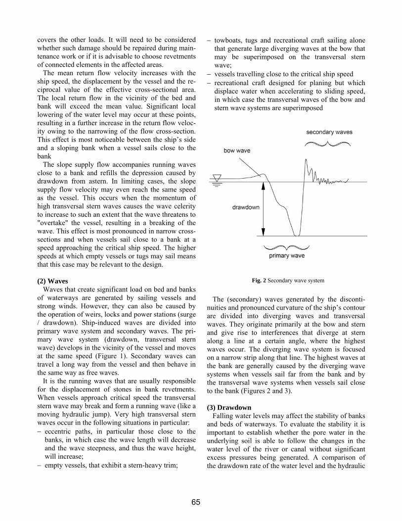
Fig. 2 Secondary wave system
covers the other loads. It will need to be considered whether such damage should be repaired during main-tenance work or if it is advisable to choose revetments of connected elements in the affected areas.
The mean return flow velocity increases with the ship speed, the displacement by the vessel and the re-ciprocal value of the effective cross-sectional area. The local return flow in the vicinity of the bed and bank will exceed the mean value. Significant local lowering of the water level may occur at these points, resulting in a further increase in the return flow veloc-ity owing to the narrowing of the flow cross-section. This effect is most noticeable between the ship’s side and a sloping bank when a vessel sails close to the bank
The slope supply flow accompanies running waves close to a bank and refills the depression caused by drawdown from astern. In limiting cases, the slope supply flow velocity may even reach the same speed as the vessel. This occurs when the momentum of high transversal stern waves causes the wave celerity to increase to such an extent that the wave threatens to "overtake" the vessel, resulting in a breaking of the wave. This effect is most pronounced in narrow cross-sections and when vessels sail close to a bank at a speed approaching the critical ship speed. The higher speeds at which empty vessels or tugs may sail means that this case may be relevant to the design.
(2) Waves
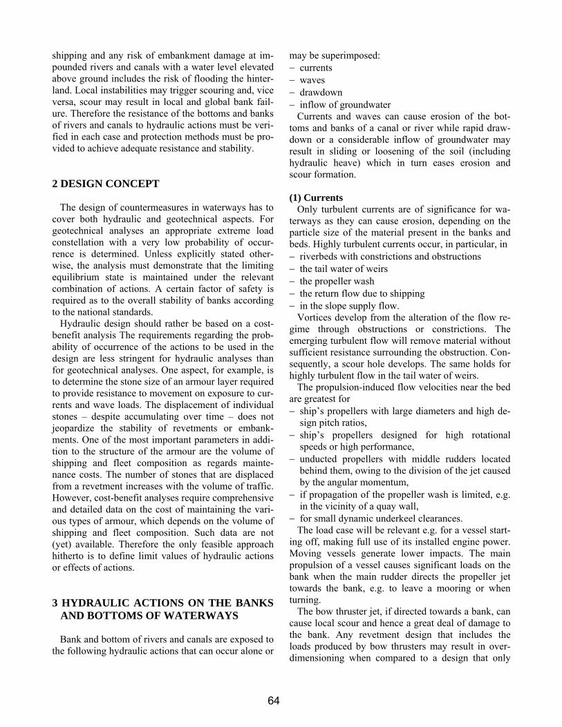
Waves that create significant load on bed and banks of waterways are generated by sailing vessels and strong winds. However, they can also be caused by the operation of weirs, locks and power stations (surge / drawdown). Ship-induced waves are divided into primary wave system and secondary waves. The pri-mary wave system (drawdown, transversal stern wave) develops in the vicinity of the vessel and moves at the same speed (Figure 1). Secondary waves can travel a long way from the vessel and then behave in the same way as free waves.
It is the running waves that are usually responsible for the displacement of stones in bank revetments. When vessels approach critical speed the transversal stern wave may break and form a running wave (like a moving hydraulic jump). Very high transversal stern waves occur in the following situations in particular: − eccentric paths, in particular those close to the
banks, in which case the wave length will decrease and the wave steepness, and thus the wave height, will increase;
− empty vessels, that exhibit a stern-heavy trim;
− towboats, tugs and recreational craft sailing alone that generate large diverging waves at the bow that may be superimposed on the transversal stern wave;
− vessels travelling close to the critical ship speed − recreational craft designed for planing but which
displace water when accelerating to sliding speed, in which case the transversal waves of the bow and stern wave systems are superimposed
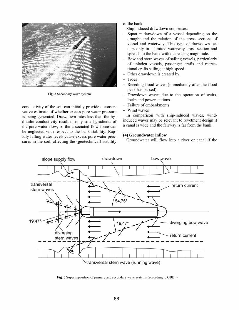
The (secondary) waves generated by the disconti-nuities and pronounced curvature of the ship’s contour are divided into diverging waves and transversal waves. They originate primarily at the bow and stern and give rise to interferences that diverge at stern along a line at a certain angle, where the highest waves occur. The diverging wave system is focused on a narrow strip along that line. The highest waves at the bank are generally caused by the diverging wave systems when vessels sail far from the bank and by the transversal wave systems when vessels sail close to the bank (Figures 2 and 3).
(3) Drawdown
Falling water levels may affect the stability of banks and beds of waterways. To evaluate the stability it is important to establish whether the pore water in the underlying soil is able to follow the changes in the water level of the river or canal without significant excess pressures being generated. A comparison of the drawdown rate of the water level and the hydraulic
65
4
conductivity of the soil can initially provide a conser-vative estimate of whether excess pore water pressure is being generated. Drawdown rates less than the hy-draulic conductivity result in only small gradients of the pore water flow, so the associated flow force can be neglected with respect to the bank stability. Rap-idly falling water levels cause excess pore water pres-sures in the soil, affecting the (geotechnical) stability
of the bank. Ship induced drawdown comprises:
− Squat = drawdown of a vessel depending on the draught and the relation of the cross sections of vessel and waterway. This type of drawdown oc-curs only in a limited waterway cross section and spreads to the bank with decreasing magnitude.
− Bow and stern waves of sailing vessels, particularly of unladen vessels, passenger crafts and recrea-tional crafts sailing at high speed.
− Other drawdown is created by: − Tides − Receding flood waves (immediately after the flood
peak has passed) − Drawdown waves due to the operation of weirs,
locks and power stations − Failure of embankments − Wind waves
In comparison with ship-induced waves, wind-induced waves may be relevant to revetment design if a canal is wide and the fairway is far from the bank.
(4) Groundwater inflow
Groundwater will flow into a river or canal if the
Fig. 2 Secondary wave system
Fig. 3 Superimposition of primary and secondary wave systems (according to GBB1))
66
5
groundwater table in the slope is higher than the still-water level of the waterway. With such boundary con-dition a higher hydrostatic water pressure acts in the subsoil of the bank, giving rise to flow forces in the direction of the river or canal. All geotechnical design calculations must take such actions into account.
If groundwater flows out of an unprotected slope, the limit state for local slope stability will be reached at a slope inclination of β ≤ φ'/2 (β being the slope angle and φ' the effective angle of shearing resistance of the soil). Any outflow of groundwater from the sur-face over a fairly long period of time will cause ero-sion and should therefore be avoided.
4 DETERMINING HYDRAULIC ACTIONS For the design of protection layers in waterways the
following hydraulic design parameters are required: − maximum wave height, − maximum flow velocity, − maximum drawdown, − maximum drawdown velocity and resulting excess
pore water pressure. The values of these parameters can be determined
either by measurement or by calculation. Measure-ment data are preferable to calculated values as the latter are subject to the following limitations: − The calculation methods are based on assumptions
regarding the relevant physical processes, that work with simplified fundamental equations and use simplified geometrical data for the boundary condi-tions.
− Empirical corrections to the design approaches only apply to the scope for which measurement data is available.
− Experience is not available on individual design situation (e.g. for the wave heights caused by rec-reational craft).
It is for this reason that often more than one equa-tion is available.
As regards the accuracy of the calculation methods it should be noted that the loads resulting from the primary wave field can be determined more accurately than those arising from the secondary wave field, the slope supply flow and wind waves. Particularly it is very difficult to determine the loads due to the propul-sion units of ships as the latter depend largely on the ship design.
5 EXCESS PORE WATER PRESSURE AS A FUNCTION OF RAPID DRAWDOWN Natural surface water and pore water in the subsoil
are not an ideal, incompressible fluid. Small micro-scopic air (more generally: gas) bubbles are dispersed in the water, so the fluid shows a certain compressibil-ity. Compressible pore water causes a delayed reac-tion of the pore water pressure on any pressure change at the boundaries if the hydraulic conductivity of the subsoil is lower than the velocity of that pressure change. An example is the rapid lowering of the sur-face water level, resulting in an excess pore water in the adjacent soil. Due to this phenomenon, bank sta-bility is affected by the interaction of surface water and pore water.
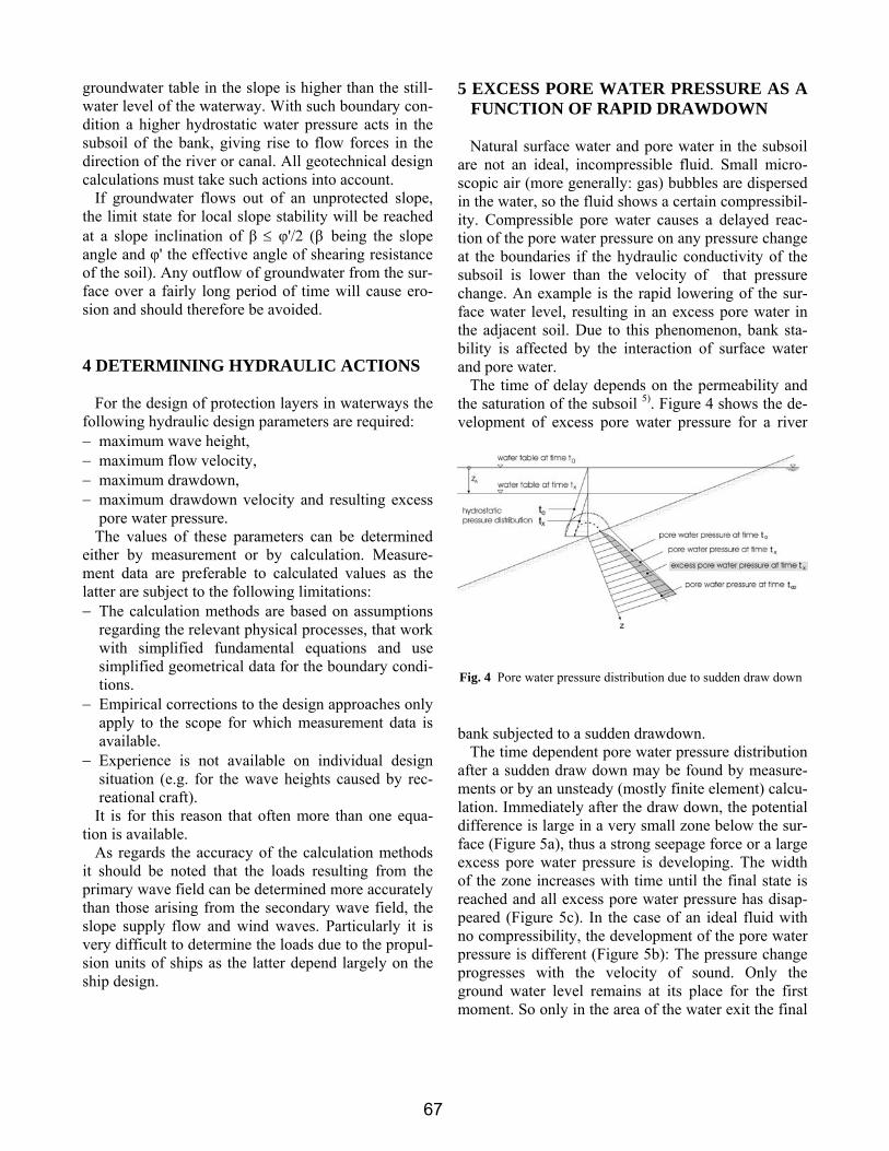
The time of delay depends on the permeability and the saturation of the subsoil 5). Figure 4 shows the de-velopment of excess pore water pressure for a river
bank subjected to a sudden drawdown. The time dependent pore water pressure distribution
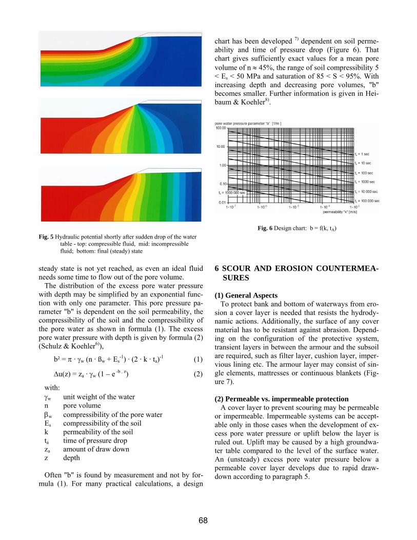
after a sudden draw down may be found by measure-ments or by an unsteady (mostly finite element) calcu-lation. Immediately after the draw down, the potential difference is large in a very small zone below the sur-face (Figure 5a), thus a strong seepage force or a large excess pore water pressure is developing. The width of the zone increases with time until the final state is reached and all excess pore water pressure has disap-peared (Figure 5c). In the case of an ideal fluid with no compressibility, the development of the pore water pressure is different (Figure 5b): The pressure change progresses with the velocity of sound. Only the ground water level remains at its place for the first moment. So only in the area of the water exit the final
Fig. 4 Pore water pressure distribution due to sudden draw down
67
6
steady state is not yet reached, as even an ideal fluid needs some time to flow out of the pore volume.
The distribution of the excess pore water pressure with depth may be simplified by an exponential func-tion with only one parameter. This pore pressure pa-rameter "b" is dependent on the soil permeability, the compressibility of the soil and the compressibility of the pore water as shown in formula (1). The excess pore water pressure with depth is given by formula (2) (Schulz & Koehler6)),
b² = π · γw (n · ßw + Es-1) · (2 · k · ta)-1 (1)
Δu(z) = za · γw (1 – e -b · z) (2)
with: γw unit weight of the water n pore volume βw compressibility of the pore water Es compressibility of the soil k permeability of the soil ta time of pressure drop za amount of draw down z depth Often "b" is found by measurement and not by for-
mula (1). For many practical calculations, a design
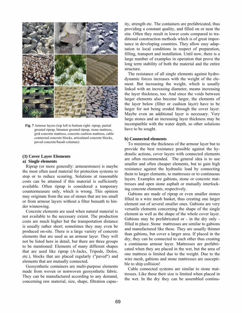
chart has been developed 7) dependent on soil perme-ability and time of pressure drop (Figure 6). That chart gives sufficiently exact values for a mean pore volume of n ≈ 45%, the range of soil compressibility 5 < Es < 50 MPa and saturation of 85 < S < 95%. With increasing depth and decreasing pore volumes, "b" becomes smaller. Further information is given in Hei-baum & Koehler8).
6 SCOUR AND EROSION COUNTERMEA-SURES
(1) General Aspects
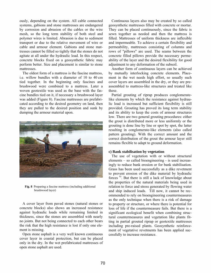
To protect bank and bottom of waterways from ero-sion a cover layer is needed that resists the hydrody-namic actions. Additionally, the surface of any cover material has to be resistant against abrasion. Depend-ing on the configuration of the protective system, transient layers in between the armour and the subsoil are required, such as filter layer, cushion layer, imper-vious lining etc. The armour layer may consist of sin-gle elements, mattresses or continuous blankets (Fig-ure 7).
(2) Permeable vs. impermeable protection
A cover layer to prevent scouring may be permeable or impermeable. Impermeable systems can be accept-able only in those cases when the development of ex-cess pore water pressure or uplift below the layer is ruled out. Uplift may be caused by a high groundwa-ter table compared to the level of the surface water. An (unsteady) excess pore water pressure below a permeable cover layer develops due to rapid draw-down according to paragraph 5.
Fig. 5 Hydraulic potential shortly after sudden drop of the water table - top: compressible fluid, mid: incompressible fluid; bottom: final (steady) state
Fig. 6 Design chart: b = f(k, tA)
68
7
(3) Cover Layer Elements a) Single elements
Riprap (or more generally: armourstones) is maybe the most often used material for protection systems to stop or to reduce scouring. Solutions at reasonable costs can be attained if this material is sufficiently available. Often riprap is considered a temporary countermeasure only, which is wrong. This opinion may originate from the use of stones that are too small or from armour layers without a filter beneath to hin-der winnowing.
Concrete elements are used when natural material is not available to the necessary extent. The production costs are much higher but the transportation distance is usually rather short; sometimes they may even be produced on-site. There is a large variety of concrete elements that are used as an armour layer. They will not be listed here in detail, but there are three groups to be mentioned: Elements of many different shapes that are used like riprap (A-Jacks, Tripods, Dolos, etc.), blocks that are placed regularly ("paved") and elements that are mutually connected.
Geosynthetic containers are multi-purpose elements made from woven or nonwoven geosynthetic fabric. They can be manufactured according to any demand, concerning raw material, size, shape, filtration capac-
ity, strength etc. The containers are prefabricated, thus providing a constant quality, and filled on or near the site. Often they result in lower costs compared to tra-ditional construction methods which is of great impor-tance in developing countries. They allow easy adap-tation to local conditions in respect of preparation, filling, transport and installation. Until now, there is a large number of examples in operation that prove the long term stability of both the material and the entire structure.
The resistance of all single elements against hydro-dynamic forces increases with the weight of the ele-ment. But increasing the weight, which is usually linked with an increasing diameter, means increasing the layer thickness, too. And since the voids between larger elements also become larger, the elements of the layer below (filter or cushion layer) have to be larger for not being eroded through the cover layer. Maybe even an additional layer is necessary. Very large stones and an increasing layer thickness may be incompatible with the water depth, so other solutions have to be sought.
b) Connected elements
To minimise the thickness of the armour layer but to provide the best resistance possible against the hy-draulic actions, cover layers with connected elements are often recommended. The general idea is to use smaller and often cheaper elements, but to gain high resistance against the hydraulic load by connecting them to larger elements, to mattresses or to continuous layers. Examples are gabions, stone or concrete mat-tresses and open stone asphalt or mutually interlock-ing concrete elements, respectively.
Gabions are made of riprap or even smaller stones filled in a wire mesh basket, thus creating one larger element out of several smaller ones. Gabions are very versatile elements concerning the shape of the single element as well as the shape of the whole cover layer. Gabions may be prefabricated or - in the dry only - filled in place. Stone mattresses are similar to gabions and manufactured like these. They are usually thinner than gabions, but cover a larger area. If placed in the dry, they can be connected to each other thus creating a continuous armour layer. Mattresses are prefabri-cated when they are placed in the wet, but the area of one mattress is limited due to the weight. Due to the wire mesh, gabions and stone mattresses are suscepti-ble to ship collision!
Cable connected systems are similar to stone mat-tresses. Like these their size is limited when placed in the wet. In the dry they can be assembled continu-
ously, depending on the system. All cable connected systems, gabions and stone mattresses are endangered by corrosion and abrasion of the cables or the wire mesh, so the long term stability of both steel and polymer wires is limited. Abrasion is due to sediment transport or due to the relative movement of wire or cable and armour element. Gabions and stone mat-tresses cannot be filled so tightly that the stones do not agitate at all under the hydraulic load. In this respect, concrete blocks fixed on a geosynthetic fabric may perform better. Size and placement is similar to stone mattresses.
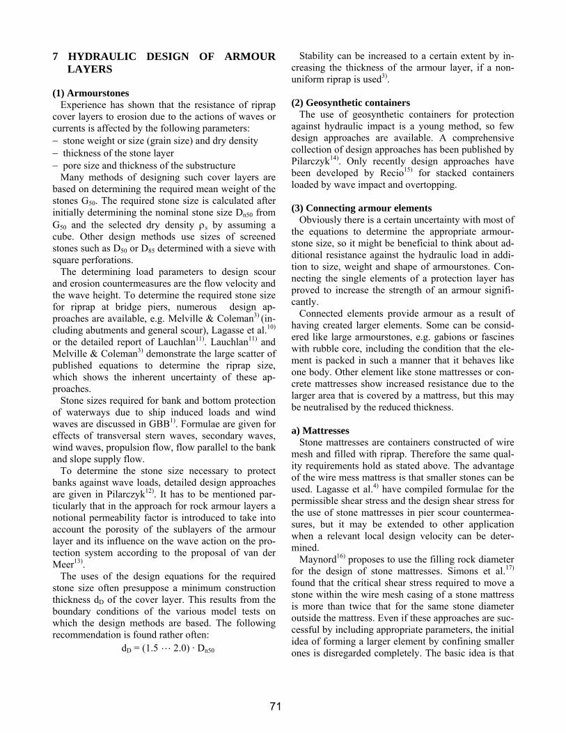
The oldest form of a mattress is the fascine mattress, i.e. willow bundles with a diameter of 10 to 40 cm tied together. In the beginning only fascines and brushwood were combined to a mattress. Later a woven geotextile was used as the base with the fas-cine bundles tied on it, if necessary a brushwood layer was added (Figure 8). Fascine mattresses are prefabri-cated according to the desired geometry on land, then they are pulled to the desired position and sunk by dumping the armour material upon.
A cover layer from paved stones (natural stones or concrete blocks) also shows an increased resistance against hydraulic loads while remaining limited in thickness, since the stones are assembled with nearly no joints. But not being connected to each other bears the risk that the high resistance is lost if only one ele-ment is missing.
Open stone asphalt is a very well known continuous cover layer in coastal protection, but can be placed only in the dry. In the wet prefabricated mattresses of open stone asphalt are used.
Continuous layers also may be created by so called geosynthetic mattresses filled with concrete or mortar. They can be placed continuously, since the fabric is sewn together as needed and then the mattress is filled. Mattresses of uniform thickness are inflexible and impermeable. To achieve a certain flexibility and permeability, mattresses consisting of columns and rows of "pillows" are used. The seams between the concrete filled pillows provide the necessary perme-ability of the layer and the desired flexibility for good adjustment to any deformation of the subsoil.
Another form of continuous layers can be achieved by mutually interlocking concrete elements. Place-ment in the wet needs high effort, so usually such cover layers are assembled in the dry, or they are pre-assembled to mattress-like structures and treated like these.
Partial grouting of riprap produces conglomerate-like elements by which the resistance against hydrau-lic load is increased but sufficient flexibility is still provided. Grouting has proved its long term stability and its ability to keep the costs of armour structures low. There are two general grouting procedures: either the grout is distributed more or less uniformly or the grouting is done line by line or spot by spot, the latter resulting in conglomerate-like elements (also called pattern grouting). With the correct amount and the correct distribution of the grout the armour layer still remains flexible to adapt to ground deformation.
c) Bank stabilisation by vegetation
The use of vegetation with or without structural elements – so called bioengineering - is used increas-ingly to reduce bank erosion or for bank stabilisation. Grass has been used successfully as a dike revetment to prevent erosion of the dike material by hydraulic forces 9). But there is still a lack of knowledge about the properties of the natural materials being used in relation to force and stress generated by flowing water and ship induced loads. Till now, it cannot be rec-ommended to rely on bioengineering countermeasures as the only technique when there is a risk of damage to property or structure, or where there is potential for loss of life if the countermeasure fails. But there is a significant ecological benefit when combining struc-tural countermeasures and vegetation like plants fit-ting in partial grouted riprap or geotextile mattresses including pre-raised plants. Geosynthetic reinforce-ment of vegetative revetments has been applied suc-cessfully to increase resistance.
Fig. 8 Preparing a fascine mattress (including additional brushwood layer)
70
9
7 HYDRAULIC DESIGN OF ARMOUR LAYERS
(1) Armourstones
Experience has shown that the resistance of riprap cover layers to erosion due to the actions of waves or currents is affected by the following parameters: − stone weight or size (grain size) and dry density − thickness of the stone layer − pore size and thickness of the substructure
Many methods of designing such cover layers are based on determining the required mean weight of the stones G50. The required stone size is calculated after initially determining the nominal stone size Dn50 from G50 and the selected dry density ρs by assuming a cube. Other design methods use sizes of screened stones such as D50 or D85 determined with a sieve with square perforations.
The determining load parameters to design scour and erosion countermeasures are the flow velocity and the wave height. To determine the required stone size for riprap at bridge piers, numerous design ap-proaches are available, e.g. Melville & Coleman3) (in-cluding abutments and general scour), Lagasse et al.10) or the detailed report of Lauchlan11). Lauchlan11) and Melville & Coleman3) demonstrate the large scatter of published equations to determine the riprap size, which shows the inherent uncertainty of these ap-proaches.
Stone sizes required for bank and bottom protection of waterways due to ship induced loads and wind waves are discussed in GBB1). Formulae are given for effects of transversal stern waves, secondary waves, wind waves, propulsion flow, flow parallel to the bank and slope supply flow.
To determine the stone size necessary to protect banks against wave loads, detailed design approaches are given in Pilarczyk12). It has to be mentioned par-ticularly that in the approach for rock armour layers a notional permeability factor is introduced to take into account the porosity of the sublayers of the armour layer and its influence on the wave action on the pro-tection system according to the proposal of van der Meer13).
The uses of the design equations for the required stone size often presuppose a minimum construction thickness dD of the cover layer. This results from the boundary conditions of the various model tests on which the design methods are based. The following recommendation is found rather often:
dD = (1.5 L 2.0) · Dn50
Stability can be increased to a certain extent by in-creasing the thickness of the armour layer, if a non-uniform riprap is used3).
(2) Geosynthetic containers
The use of geosynthetic containers for protection against hydraulic impact is a young method, so few design approaches are available. A comprehensive collection of design approaches has been published by Pilarczyk14). Only recently design approaches have been developed by Recio15) for stacked containers loaded by wave impact and overtopping.
(3) Connecting armour elements
Obviously there is a certain uncertainty with most of the equations to determine the appropriate armour-stone size, so it might be beneficial to think about ad-ditional resistance against the hydraulic load in addi-tion to size, weight and shape of armourstones. Con-necting the single elements of a protection layer has proved to increase the strength of an armour signifi-cantly.
Connected elements provide armour as a result of having created larger elements. Some can be consid-ered like large armourstones, e.g. gabions or fascines with rubble core, including the condition that the ele-ment is packed in such a manner that it behaves like one body. Other element like stone mattresses or con-crete mattresses show increased resistance due to the larger area that is covered by a mattress, but this may be neutralised by the reduced thickness.
a) Mattresses
Stone mattresses are containers constructed of wire mesh and filled with riprap. Therefore the same qual-ity requirements hold as stated above. The advantage of the wire mess mattress is that smaller stones can be used. Lagasse et al.4) have compiled formulae for the permissible shear stress and the design shear stress for the use of stone mattresses in pier scour countermea-sures, but it may be extended to other application when a relevant local design velocity can be deter-mined.
Maynord16) proposes to use the filling rock diameter for the design of stone mattresses. Simons et al.17) found that the critical shear stress required to move a stone within the wire mesh casing of a stone mattress is more than twice that for the same stone diameter outside the mattress. Even if these approaches are suc-cessful by including appropriate parameters, the initial idea of forming a larger element by confining smaller ones is disregarded completely. The basic idea is that
71
10
the larger element (gabion or stone mattress) can resist the hydraulic load much better than a single fill ele-ment and the casing made of wire mesh or else has to be sufficiently robust to keep the fill inside even if the fill material is dislodged.
For articulated grout filled mattresses Lagasse et al.4) propose a design procedure. The main destabiliz-ing factors are drag and lift forces acting on the mat-tress. The application requires pressure relief holes ("weepholes") to avoid any uplift force due to pore water pressure beneath the mattress. A filter is re-quired to hinder winnowing through the weepholes. Taking into account that the weepholes have a rather limited area compared to the area of the whole mat-tress and that a filter will furthermore reduce the ef-fective open area, a certain excess uplift pressure will remain.
Fascine mattress are used for bank and bottom pro-tection in large rivers. They are covered by ar-mourstones that have to be designed as riprap (para-graph 7.1).
b) Interlocked elements
Similar to mattresses, hydraulic resistance is pro-vided by articulating concrete elements. Such systems consist of preformed concrete units that interlock, are held together by steel rods, or are bonded to a geotex-tile fabric. General hydraulic design approaches are not known, in most cases the necessary information is provided by the manufacturer because of the many variations in shape, size and weight. Application re-marks are given by Lagasse et al.4). A problem may arise due to the fact that such protection layers are of limited thickness only. So the weight might be not sufficient to stabilise the underlying soil (geotechnical stability) and the vulnerability as to mechanical dam-age is increased. Design proposals concerning wave attack are published by Klein Breteler & Bezuijen 18).
c) Partial grouting
Field tests and experience have shown that partially grouted cover layers provide adequate resistance to all known hydraulic actions occurring on waterways, if the grouting has been performed correctly. For suc-cessful grouting the riprap size should not be too large (grout will flow through the large voids) and not too small (grout ca not penetrate into the voids). An ap-propriate grading is CP90/250 according to EN 13383-131). Using smaller stones it becomes more difficult to achieve the desired distribution with depth while the voids of larger stones are too big to retain the grout and the contact area of two stones is too small. With
respect to tests, hydraulic design is not required in this case provided that the maximum flow velocity does not exceed 8 m/s1). Laboratory tests at the Braun-schweig University, Germany, proved stability up to that flow velocity (test report unpublished). Quantity and quality of grout should be chosen according to MAV19) and being tested according to RPV20) (both 1991 editions available in English – new German edi-tion 2008). To maintain sufficient permeability, less than 50% of the voids are filled with grout.
(4) Continuous layers
Continuous layers like asphalt concrete, open stone asphalt, mastic and fully grouted riprap will withstand nearly all hydraulic forces occurring in waterways unless the layer remains intact and does not show a breach where the hydraulic forces can proceed to the ground or under the layer. Heavy wave action will cause impact forces on the layer, resulting in bending stress. For bituminous revetments, an approach is given by van Herpen21).
8 DESIGN OF FILTERS The majority of filter rules implies laminar flow
more or less perpendicular to the filter-base interface. That approach holds for flow towards a drain or a well. Looking at filters in scour countermeasures, the main flow is parallel to the interface, but there is a secondary reversing flow perpendicular to the inter-face of unknown intensity which is decisive for the design of filters in waterways. In German canals with standard cross section, a passing ship induces an un-steady reversing flow perpendicular to the interface of about 10-20 Hz. This value may change with the size of the vessels and the cross section of the waterway. As this secondary flow is still not sufficiently under-stood, it is proposed to use geometrical sandtight granular filters following the criteria of Cistin / Ziems or to install geotextile filters designed accordingly. An overview of filter rules applying to scour and erosion countermeasures and is given by Heibaum22).
When trying to obey filter rules in scour preventing armour layers the question arises as to the validity with regard to the particle size. All filter rules were developed for particle sizes from coarse silt to fine gravel. Only few are based on test with coarser grained material, but even in those cases diameters of about 70 mm were the maximum. Armourstones are much larger, so are the voids, which results in turbu-lent flow at the interface of filter and armour. No tra-
72
11
ditional filter criterion does really cover the boundary conditions that apply to scour and erosion protection measures using armourstones. It was found empiri-cally that some geometrical filter rules can be ap-plied22).
Hydraulic criteria should be used with caution, since the necessary parameters – hydraulic gradient and/or hydraulic conductivity – are difficult to determine or the assumptions made in the approach may not suit the actual site. Nevertheless, in some cases, hydraulic filter criteria have lead to satisfactory results, but there is still no general valid approach. Also new proposals have been issued: Hoffmans et al.23) propose a shear stress based approach for further discussion. The si-multaneous instability of filter and base is assumed. The approach shows that for flow parallel to the filter layer the relation of the decisive grain diameters fol-lowing the design of Terzaghi or Cistin/Ziems is much too strict for usual turbulence intensities. The authors assume that with increasing turbulence the shear stress based approach will come closer to the geometrical sandtight filter. The approach does not take into ac-count any other flow than parallel to the filter. So the situation in situ, where groundwater flow and surface flow interact, is not covered. Anyway, the approach shows - similarly to classical filter rules like Cistin/Ziems - an increasing diameter ratio for filter and base when the grain size distribution of the filter material is broader than the base material.
It is an advantage of geotextile filters that they can be used (nearly) irrespective of the void size of the armour. Tests are recommended for geotextile filters in severe applications (e.g. MAG24)). For a good esti-mate, the filter rules of Holtz et al.25) or Lafleur26) can be applied.
9 STABILITY OF PROTECTION LAYER AND SUBSOIL ("GEOTECHNICAL STA-BILITY")
A distinction between the local and global stability
of permeable and impermeable revetments must be made in the geotechnical design of cover layers. The design must ensure local stability for the load case in which excess pore water pressure occurs as a result of rapid drawdown of the water level, and the required mass per unit area of the revetment must be deter-mined. The global stability of the water-side slope must be checked in any case.
Usually Bishop's method is used to calculate slope stability. To introduce the excess pore water pressure it would be wrong to use in the verification the water pressure according to the height of the phreatic line over the point of the circular slip surface considered, as is done by many calculation programs. Instead, the pore water pressure according to the (unsteady and non-linear) flow field has to be taken into considera-tion.
A finite element deformation calculation allows to estimate a zone with a high probability of sliding due to excess pore water pressure (Figure 9), rather paral-lel to the surface. This limit state is often termed "lo-cal stability" in contrast to the "global stability" of slopes with deep seating (more or less circular) failure mechanisms.
(1) Local stability of permeable armour layers To verify the local stability, the required weight per
unit area of permeable revetments has to be deter-mined. The rapid drawdown of the water level of a river or canal is always accompanied by excess pore water pressures in the soil close to the surface of the bed and banks of the canal or river as discussed in paragraph 5. In the case of permeable revetments − sliding may occur along a failure surface in the
ground parallel to the slope at a certain critical depth below the revetment as shown on Figure 9 (not relevant for partial grouted riprap) or
− hydrodynamic soil displacement may occur directly below the revetment if the revetment has an insuffi-cient weight per unit area, depending on the degree and velocity of drawdown.
Geotechnical analyses for both types of failure must always be carried out.
Usually, an armour layer has a certain toe support, e.g. toe blanket, embedded toe or sheet pile wall sup-port, that allows for a certain toe support force that may be taken into consideration when verifying local stability. Two failure mechanisms are possible for supported slope revetments (riprap armour): − The revetment shears off in a horizontal joint pass-
ing through the upper edge of the toe of the revet-ment.
− Failure of the toe of the revetment. Corresponding approaches are given in GBB1). Sus-
pended revetments as an alternative to toe support are also discussed.
The internal bond of partially grouted cover layers is sufficient to transfer forces to lateral, unloaded areas. As the extent of dynamic hydraulic actions on cover layers due to passing ships is limited, verification that the cover layer provides safety against sliding and shearing is not required. An embedded toe (toe exten-sion) is required to provide protection against scour in unprotected bottoms.
(2) Local stability of impermeable armour
layers Impermeable revetments must be designed to with-
stand the maximum excess water pressure if the ground water level may be higher than the lowered water level in the canal. The weight per unit area of impermeable revetments must be great enough to pre-vent sliding on the slope or uplift at the bed. If the slope lining is capable of transferring longitudinal forces to the toe, the weight must sufficiently high to prevent uplift 1).
10 PLACEMENT OF PROTECTION MA-TERIAL BELOW THE WATER LEVEL
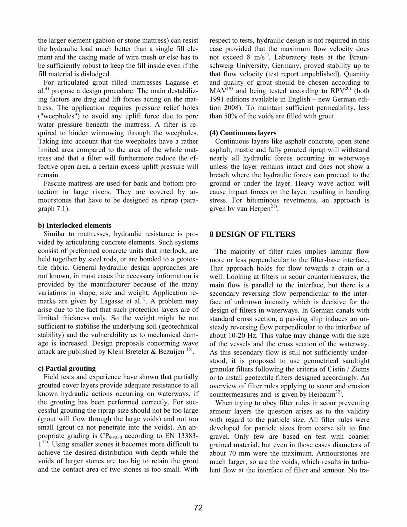
(1) Granular Material
Any granular material, armourstones as well as granular filters, may be placed by an excavator or by dumping the material from a special pontoon (Figure 10). It is the advantage of dumping that a large amount of fill can be placed in short time. But it is the disadvantage that only narrowly graded grain size dis-tributions may be used, since otherwise there will be segregation while falling through the water. The coarse material will reach the bottom first and the fines will be on top - just the opposite to what is de-sired.
If only narrow grain size distribution can be used for granular filters, nearly always more than one layer has
to be installed. Each layer needs a minimum thickness to guarantee the necessary filtration length and to avoid bare spots caused by to the irregular surface of the subsoil. If there are rather steep slopes of the scour hole, it has to be verified that the filter material will not slide. Often the current velocity disables the place-ment of a grain filter at all.
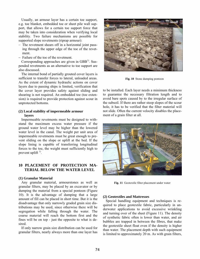
(2) Geotextiles and Mattresses Special handling equipment and techniques is re-
quired to place geotextile fabric, particularly in un-derwater applications to avoid excessive wrinkling and turning over of the sheet (Figure 11). The density of synthetic fabric often is lower than water, and air bubbles are trapped in between the fibres, that make the geotextile sheet float even if the density is higher than water. The placement depth with such equipment is limited to approximately 20 m. As with grain filters,
Fig. 10 Stone dumping pontoon
Fig. 11 Geotextile filter placement under water
74
13
any current will hinder a proper placement of a geo-textile filter. In mild currents up to ca. 0,8 m/s, a "sandmat" - a sand fill up to 9 kg/m² in between two geosynthetic cloths – can be installed.
Floating complicates also the placement of geosyn-thetic concrete mattresses because they are filled in place only after installing the geotextile sheets. Other mattresses are assembled in the dry and placed by special cranes. Fascine mattresses are prefabricated in the dry, pulled to the installation position and drowned by dumping riprap upon.
Steep banks of a scour hole require sufficient fric-tion of geotextile and subsoil. Nonwovens exhibit a higher angle of friction than wovens, so the fabric can be chosen according to the local demands.
(3) Geosynthetic containers
Containers are placed by hand, by an excavator, by side dumping vessels or by split barges. Care has to be taken that an area to be protected is covered com-pletely (which does not apply to current training struc-tures, for example). Special equipment allows for very precise placement of containers. When using geosyn-thetic containers to form a filter layer, the amount of fill should not exceed 80% of the theoretical volume, since tightly filled containers will not adjust them-selves to the subsoil, to structures or to the neighbour-ing geocontainers.
(4) Grouted armourstones
For the placement of grout below the water table special equipment is needed. Only to a water depth less than 1 m grouting can be done by hand. The grout must not segregate when poured or dumped on the riprap. This is achieved by chemical additives or by high speed centrifugal mixing (colloidal mortar). The consistency of the grout should be such that the amount of fill is decreasing from top to bottom. The system and the grout chosen have to prove their abil-ity by tests, since the grout behaves different in the dry and under water and is depending on the water quality. Usually test boxes with a base of at least 1 m² are installed under water, filled with armour layer ma-terial and lifted again after being grouted to check the result.
11 DURABILITY Factors that affect a material's durability include its
ability to resist abrasion, chemical attack, biodegrada-tion, wet/dry cycles, freeze/thaw cycles, etc.
Durability of stone depends on the geology of the rock. Sedimentary rock is usually stratified and sub-ject to failure through shear stress, impact, chemical deterioration, or changes in water content. Sedimen-tary armour stones generally are more easily worn down by abrasion. Any armour stone that develops small cracks may eventually fracture due to freeze/thaw cycles, irrespective of the type of rock. In Europe, the standard EN 13383-131) defines gradings based on stone diameter up to 250 mm and based on weight from 10 to 15000 kg. Physical requirements like density, resistance to wear and breakage, and chemical requirements are listed as well as durability aspects, e.g. resistance to freezing and thawing and to salt crystallization. Corresponding test methods to these requirements are given in the standard EN 13383-232). This standard replaces numerous national regulations and can be recommended for worldwide use.
Quartz sand is very durable, but sand mixtures with a high carbonate content from shell material will be more vulnerable to chemical attack if the water is acidic. Also shell particles are not as hard as quartz and are more susceptible to abrasion.
Concrete is considered to be durable while asphalt, according to the Coastal Engineering Manual 27) is not considered to be a durable material because it has low strength in both compression and tension, it is subject to chemical reaction, its stiffness changes with tem-perature, and it is not resistant to impact or abrasion.
Geotextiles and many plastics are generally resistant to chemical and biological attack, but will deteriorate when exposed to ultraviolet radiation and might be degraded by abrasion. The rate of UV-deterioration can be reduced by adding inhibitors. Usually geotex-tiles are covered with other layers (armour or soil). But there are successful examples of hydraulic struc-tures like groynes and revetments built of geotextile containers without protection 28) 29).
Care must be exercised in placing the overlying stone layers to avoid puncturing the geotextile. The choice of a nonwoven geotextile for geocontainers will minimise the risk of damage during placement due to its high extensibility. By allowing large defor-mations it will be able to withstand the impact load when hitting the ground as well as when the stones are dumped upon.
Since there is always some space for the ar-mourstones of a protection layer to rock on the geo-textile, the fabric must be resistant against abrasion. In Germany, all fabric that is used as filters in waterways has to pass tests to confirm sufficient resistance
75
14
against puncturing and abrasion (MAG24)), which is tested according to the corresponding guidelines (RPG 30), both available in English).
Another important factor providing durability of a scour and erosion countermeasure is flexibility. Flexi-bility is the property of a material that allows it to bend without breaking. Flexibility can also be used to describe the response of the whole protection struc-ture. For instance, the individual armourstones have no flexibility, but the entire armour layer is capable of movement and settlement to a new position without undue loss of functionality.
Materials and structures with good flexibility will help absorb cyclic and impact loads, but continual flexing might eventually lead to fatigue failure, plastic deformation, and crack formation. The relative flexi-bility of structures makes them more suitable for with-standing earthquake loads with usually only minor settlement or damage to the armour layers. Mono-lithic-type structures are less likely to survive seismic loading unscathed. Sufficient flexibility allows a structure to follow ground deformation, e.g. caused by suberosion, internal erosion, piping or other hydrody-namic soil transport in the ground, while rigid struc-ture will be undermined. So it is strongly recom-mended to use flexible structures for scour and ero-sion protection measures.
12 SUMMARY In waterways, special attention has to be paid to the
stability of banks to guarantee the necessary channel cross section to allow for easy and safe navigation. In rivers and estuaries often, and always in navigational canals, a bank protection, and sometimes also a bot-tom protection has to be installed. To design riprap protection, a large number of design equations is available. Much fewer and less approved approaches are available for alternative scour and erosion protec-tion, therefore the design should be always on the safe side. In many applications, the filter design has been neglected, resulting in short lifetime of scour coun-termeasures. One reason might be the problem of placing a granular or geosynthetic filter under current and wave actions. But placing problems can be over-come with an appropriate effort. If also durability re-quirements are met, scour and erosion protection in waterways can be accomplished successfully using the materials and equipment available today.
REFERENCES 1) GBB: Principles for the design of bank and bottom protection
for inland waterways. Mitteilungsblatt der Bundesanstalt für Wasserbau Nr. 88. Karlsruhe: Eigenverlag 2005 (http://www.baw.de/vip/publikationen/Mitteilungsblaetter31216/index.php?id=88 )
4) Lagasse, P.F., Clopper, P.E.; Zevenbergen, L.W.; Girard, L.G.: Countermeasures to protect bridge piers from scour. NCHRP report 593. Washington: Transportation research board 2007
5) Koehler, H.J.: The influence of hydraulic head and hydraulic gradient on the filtration process. In Brauns, Heibaum, Schuler (Ed.): Filters in Geotechnical and Hydraulic Engineering. Balkema, Rotterdam, 1993, pp.225-240.
6) Schulz, H.; Köhler, H.-J.: A soil mechanical design approach for permeable revetments on inland waterways. ECSMFE, Amsterdam 1999
7) Bezuijen, A.; Köhler, H.-J.: Filter and revetment design of water imposed embankments induced by wave and draw-down loadings. DeGroot, Den Hoedt, Termaat (Ed.): Geosyn-thetics: Applications, Design and Construction. Rotterdam: Balkema 1996, pp.1007-1023
8) Heibaum, M.; Köhler, H.-J.: Excess pore water pressure and slope stability. In: Proceedings GeoEng2000, Int. Conf. on Geotechnical and Geological Engineering, 20.-24.Nov.2000, Melbourne, Australia
9) Seijffert, J.W.: Grass covers and reinforcement measures. In: Pilarczyk, K. (Ed.): Dikes and revetments. Rotterdam: Balkema 1998, pp. 289-302
11) Lauchlan, C.S.: Pier scour countermeasures.Scholl of Engi-neering report No.590. University of Auckland, 1999
12) Pilarczyk, K. (Ed.): Dikes and revetments. Rotterdam: Balkema 1998
13) Van der Meer, J.W.: Conceptual design of rubble mount breakwaters. Delft Hydraulics publication No. 483
14) Pilarczyk, K. (Ed.): Geosynthetics and Geosystems in hydrau-lic an coastal engineering. Rotterdam: Balkema 2000
15) Recio, J.A: Hydraulic stability of geotextile sand containers for coastal structures. PhD-Thesis Univ. of Braunschweig, Germany, Faculty of Architecture, Civil Engineering and En-vironment. 2008
16) Maynord, S.T.: Gabion-mattress channel-protection design. Journal of hydraulic engineering Vol. 121 No.7, 1995, pp. 519-522
17) Simons, D.B.; Chen, Y.H.; Swenson, L.J.: Hydraulic tests to develop design criteria for the use of Reno mattresses. Report, Colorado state university, Fort Collins, 1984
18) Klein Breteler, M.; Bezuijen, A.: Design criteria for placed block revetments. In: Pilarczyk, K. (Ed.): Dikes and revet-ments. Rotterdam: Balkema 1998, pp. 217-248
19) RPV: Guidelines for Testing Cement Bonded and Bituminous Materials for Grouting of Armorstones on Waterways,
76
15
Karlsruhe: Bundesanstalt für Wasserbau (Fed. Waterways En-gineering and Research Inst.) Eigenverlag, 2008
20) MAV: Code of Practice “Use of Cement Bonded and Bitumi-nous Materials for Grouting of Armourstones on Waterways” Karlsruhe, Germany: BAW - Bundesanstalt für Wasserbau (Fed. Waterways Engineering and Research Inst.) 2008
21) Herpen, J.A. van: Bituminous revetments. In: Pilarczyk, K. (Ed.): Dikes and revetments. Rotterdam: Balkema 1998, pp. 249-288
22) Heibaum, M.: Geotechnical filters - the important link in scour protection In: Chiew, Y.-M.; Lim, S.-Y.; Cheng, N.-S.: 2nd International Conference on Scour and Erosion, November 14-17, 2004, Singapore: Nanyang Technology Univ, Maritime Research Centre; pp.13-28
23) Hoffmans, G.J.C.M; Adel, H.den; Verheij, H.J: Shear stress concept in granular filters. In: Briaud, J.L.: Scour of Founda-tions. Proc. Int. Symp. 19. Nov. 200, Melbourne, Australia, pp.372-379
24) MAG: Code of Practice "Use of Geotextile Filters on Water-ways (MAG)". Karlsruhe, Germany: BAW - Bundesanstalt für Wasserbau (Fed. Waterways Engineering and Research Inst.), 1993. (http://www.baw.de/vip/publikationen/merkblaetter.php.html)
27) U.S. Army Corps of Engineers. Coastal Engineering Manual. Engineer Manual 1110-2-1100, Washington: U.S. Army Corps of Engineers, 2002.
28) Hornsey, W.P.; Heerten, G.; Jackson, L.A., Restall, S.J.: Case study showing the growth and development of geotextile sand containers: an Australian perspective. In: Geotextiles and Ge-omembranes Vol. 20, 2002, pp. 231-342
29) Heibaum,M.; Oberhagemann,K.; Faisal, M.A.; Haque, S.: Geotextile bags for sole permanent bank protection. Proc. 4. European Conf. on Geosynthetics, Edinburgh, 2008
30) RPG: Guidelines for Testing Geotextile Filters in Navigable Waterways (RPG). Karlsruhe, Germany: BAW -Federal Wa-terways Engineering and Research Institute, 1993. (http://www.baw.de/vip/publikationen/sonderinfo/richtlinie.php.html)
31) EN 13383-1. Armourstone – part 1: specification. European standard 2002
32) EN 13383-2. Armourstone – part 2: test methods. European standard 2001