Page 1
Proceedings of the International Conference on Industrial Engineering and Operations Management
Washington DC, USA, September 27-29, 2018
© IEOM Society International
DESIGN AND SIMULATION OF UPFC AND IPFC FOR
VOLTAGE STABILITY UNDER A SINGLE LINE
CONTINGENCY: A COMPARATIVE STUDY
Okampo John Ewaoche and Nnamdi Nwulu Department of Electrical & Electronic Engineering Science,
Faculty of Engineering and Built Environment,
University of Johannesburg,
South Africa
[email protected] , [email protected]
Abstract
Reactive power imbalances lead to voltage instability and these are major problem in power systems. This
study presents a comparative analysis of the performance of Unified Power Flow Controller (UPFC) and
Interline Power Flow Controller (IPFC) for the enhancement of voltage stability and improvement of the
transmission system. The two devices under review are two of the most advanced classes of Flexible
Alternating Current Transmission System (FACTS) devices. An IEEE 30-bus transmission line system is
modelled with MATLAB/Simulink software. The novelty of the study is the design of a new model of
IPFC using the Sim-block of Static Synchronous Series Compensator (SSSC) in MATLAB Simulink.
Three scenarios were investigated to evaluate the developed system. In scenario one, the 30-bus network
system is modelled and simulated without any compensating device. For scenario two, the system is
modelled with UPFC incorporated while scenario three has IPFC modelled. The system models are
design to have a single line to ground fault of resistance 0.010Ω and ground resistance of 0.001Ω occur at
bus 1. The fault is expected to cause instability in the system and be cleared after 0.05sec in all cases. The
simulated results of the three cases were compared to determine the device with a better performance in
improving the voltage stability of the system. The results show that both devices stabilized the system
voltages with UPFC having a slightly better improvement of voltage magnitude while IPFC on the other
hand had the advantage of stabilizing voltages on double lines. The study has thus, increased insight on
the use of both devices in the transmission system.
Keywords
MATLAB, Simulink, FACTS, UPFC, IPFC, Compensator/Controller
1369
Page 2
© IEOM Society International
1. Introduction
The demand for quality, reliable and stable electrical power is always on the increase thus putting pressure on the
power system. Pressure such as overloading of the system could lead to reactive power imbalances which in turn
lead to voltage instability. Voltage instability is a major problem in power system networks. It results in recurrent
voltage collapses which are usually seen as outages and blackouts. This problem reflects unreliability of the system
which requires serious attention (Anulekha et al. 2012).
In trying to meet the increasing demand for power, new power transmission lines could be built or the existing ones
can be restructured. Both options are expensive and time consuming. “A better and effective option for tackling
these problems is by the introduction of high power electronic controllers that can absorb or inject reactive power as
required by a particular power system. FACTS (Flexible Alternative Current Transmission System) devices are one
of the most effective sources of reactive power. These devices enhance operational flexibility yet do not stress the
system” (Bisen and Shrivastava 2013).
According to Bindeswar et al. (2011), the following are other benefits of employing FACTS:
Reduction of system losses, voltage stability and security improvement
Improvement of dynamic and transient stability to improve line capacity
Control of real and reactive power for power profile and quality improvement
Flexibility in operation
This study investigates the performance of UPFC and IPFC connected to a 132KV transmission line. The aim is to
determine the best device to be used in the particular network under consideration. The remainder of this paper is
organized thus: Section II presents an overview of FACTS devices, Section III details the research methodology
used in this work, section IV analyses the results and section V is the conclusion.
2. Overview of Facts Devices
Advancements in power electronics have shown considerable improvement in satisfying the need for voltage
stability and power quality improvement via the introduction of FACTS devices (Bhanu et al. 2003). The main
functions of these devices are reactive power compensation, voltage control and power flow control to enhance
better power quality in modern power systems (Seifi et al. 2010).
Before the advent of FACTS devices were mechanically controlled capacitors, inductors and phase shifting
transformers with mechanical on-load tap changers. The first generation were developed such that thyristor valves
replace the mechanical switches. This gave a significant improvement in the speed of the devices. The second
generation were designed using voltage source converter based devices. These devices provide multiple and total
control of the power system parameters (Acha et al. 2004).
According to Hingorani and Gyugyi (2000), FACTS controllers can be divided in four categories as follows:
2.1 Series Controllers
Series Controllers inject voltage in series with the line. They are used to reduce the transfer reactance of a power line
and hence increase transmission line capacity and improve system stability. Example of series controllers are Thyristor Controlled Series Compensator (TCSC) and SSSC (Zhang et al. 2006).
2.2 Shunt Controllers
Shunt controllers are mainly used in high voltage systems to improve voltage profile, by supplying reactive power as
they inject current into the system at the point of connection. Static Var Compensator (SVC) and Static Synchronous
Compensator (STATCOM) are such controllers (Mithu 20013).
2.3 Combined Series-Series Controllers
This is a series combination of separate series controllers, which are coordinately controlled, in more than one
transmission line system. The IPFC belongs to this category (Pramod et al. 2012).
1370
Page 3
© IEOM Society International
2.4 Combined Series-Shunt Controllers
These are controllers that have combined shunt and series controllers, which have sophisticated control. When the
shunt and series controllers are jointly used, there can be a real power exchange between them through their shared
DC link. The UPFC is a series-shunt controller (Pramod et al. 2012).
The two FACTS devices used in this work are described in the subsequent subsections:
2.5 Interline Power Flow Controller (IPFC)
IPFC has two series converters connected to two different transmission lines as shown in Figure 1. It provides a very
good power flow control for more than one transmission lines with each of the two SSSC giving series power
addition for its own transmission line. The two converters are joined through a DC capacitor and attached to the AC
network through transformers directly connected. By this, it does not only provide reactive power addition but
furthermore, any of the converters can be manipulated to inject real power to the DC joint from its own transmission
line. And also any of the IPFC converters can move real power to the other and by implication real power exchange
between the lines may be carried out in other to create a balance between overloaded and under loaded lines
controlling reactive series compensation of each individual line (Mohamed, 2002).
Figure 1. Schematic diagram of IPFC (Mohamed, 2002)
The IPFC concept applied for two lines can be generalized for multiple lines, thus, under-loaded lines can share the
power from overloaded lines in other to optimize the transmission system utilization. The net real power exchanged
by all the converters must be zero.
2.6 Unified Power Flow Controller (UPFC)
The UPFC is considered as one of the most versatile and powerful FACTS devices in power system today. “It is
primarily used for flexible control of powers for better voltage stability. The UPFC allows concurrent or
independent control of these parameters with transfer from one control scheme to another in real time”. (Pramod et
al. 2012)
Figure 2. Schematic diagram of UPFC (Mohamed, 2002)
1371
Page 4
© IEOM Society International
UPFC as shown in Figure 2 is design using STATCOM and SSSC linked together with a DC. The converters are
connected to the line with transformers. The unique combination of this device allows for flexibility of operation
when connected to the power system network.
This paper limits its scope to UPFC and IPFC. Since there are many FACTS devices that perform similar functions,
there is a need for comparative study to determine which of the FACTS devices is best for a particular system. Due
to the hybrid structure of the UPFC and the IPFC, it is obvious that they are constructed for better performance than
the other FACTS devices as they combine the functions of the other devices. But what is not very obvious is the
relative performance of these two advanced FACTS devices under contingency, thus the need for their comparative
study. The study will explore the advantages of these devices (UPFC and IPFC) and suggest which is more adequate
for a particular power system considering cost effectiveness and efficiency of the devices in improving voltage
stability in the system.
3. Research Methodology
An IEEE 30-bus transmission line system is model with MATLAB/SIMULINK software in three scenarios:
In scenario one, the original transmission line system is model and simulated without any compensating device.
The system is modelled with UPFC incorporated in scenario 2 while
Scenario 3 has IPFC incorporated.
For each scenario, the system is designed to have a single line to ground fault of resistance 0.010Ω and ground
resistance of 0.001Ω occur at bus 1. The fault is expected to cause instability in the system and be cleared after
0.05sec in the three scenarios. The system had bus 1 as the reference bus, 6 generator buses and 23 load buses with
flat data values of nominal voltage of 132KV (1.0pu).
Figure 3 below shows the IEEE 30-bus system to be considered for modelling and simulation.
Figure 3 IEEE 30-bus power transmission line network
1372
Page 5
© IEOM Society International
There is a measurement and control unit as the subsystem of both UPFC and IPFC. These units are designed
separately and configured together to form the overall model of both the UPFC and IPFC.
Figure 4 is a model of pack transformation which enables the transformation of three phase (abc) natural input
variables such as voltages to direct-quadrature-zero (dq0) rotating reference frame.
Figure 4. Model of abc to dq0 transformation
In transforming abc to dq0 signal the following equations are used:
(1)
(2)
(3)
Where w = rotation speed (rad/s) of the rotating frame.
Figure 5 is the power computation model.
Figure 5. Real and reactive power computation model
Equation (4) and (5) are for the computation of real and reactive power respectively.
(4)
(5)
Figure 6 is the model of the control unit of both the UPFC and the IPFC.
1373
Page 6
© IEOM Society International
Figure 6. UPFC and IPFC control subsystem
The STATCOM and SSSC are configured together with the control unit in Figure 6 to form the UPFC model in
Figure 8, while two SSSC models are combine with the control unit to form the IPFC in Figure 10. Figure 7 is the Simulink model of the 30-bus system under consideration without any compensating device.
Figure 7. Scenario 1: Simulink model of original 30-bus system without compensating devices
1374
Page 7
© IEOM Society International
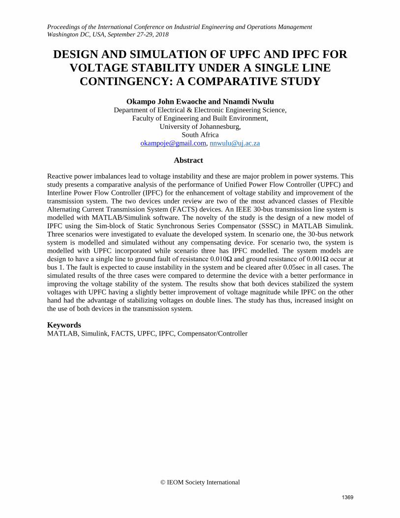
Figure 8. UPFC subsystem configuration
The UPFC subsystem is configured to consist Simulink blocks of two different converters (STATCOM and SSSC)
sharing a common capacitor on their DC side and a unified control system as shown in Figure 8. It provides
concurrent control of power system parameters such as active power, reactive power and voltage magnitude. It can
also be set to control one or more of these parameters in any combination or none of them. In figure 9, the system is
model with UPFC incorporated between bus1and bus3 (i.e. line 1-3). The shunt converter draws the real power
needed by the series converter from the AC network and supply through the DC link. The voltage inverted from the
series converter is added to the bus voltage, at bus 1 to boost the nodal voltage at bus 3
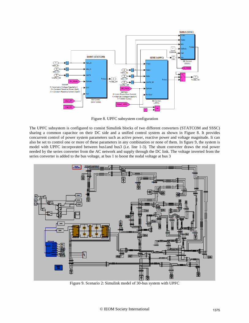
Figure 9. Scenario 2: Simulink model of 30-bus system with UPFC
1375
Page 8
© IEOM Society International
The IPFC model is configured to consist Simulink blocks of two SSSCs connected back-to-back through the DC
link as shown in Figure 10. The converters produce a controllable AC output voltage. The real power taken from one
line must be given to the other line. Therefore, the IPFC is capable to control both real and reactive power flow
between the lines (1-3 and 3-4); thus transfer power from the overloaded line to under-loaded line. The voltage
component is controlled in such a way to compensate against resistive line voltage drop or to increase the
effectiveness of the compensating system for dynamic disturbances.
Figure 10. IPFC configuration
In figure 11, the system is model with IPFC having one of its SSSC converter connected to line 1-3 and another
connected to line 3-4.
Figure 11.Scenario 3: Simulink model of 30-bus system with IPFC
1376
Page 9
© IEOM Society International
4. Results and Analysis of Results
4.1 Simulated Result of Scenario 1
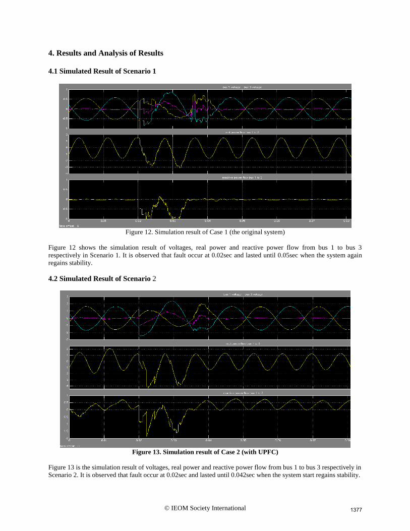
Figure 12. Simulation result of Case 1 (the original system)
Figure 12 shows the simulation result of voltages, real power and reactive power flow from bus 1 to bus 3
respectively in Scenario 1. It is observed that fault occur at 0.02sec and lasted until 0.05sec when the system again
regains stability.
4.2 Simulated Result of Scenario 2
Figure 13. Simulation result of Case 2 (with UPFC)
Figure 13 is the simulation result of voltages, real power and reactive power flow from bus 1 to bus 3 respectively in
Scenario 2. It is observed that fault occur at 0.02sec and lasted until 0.042sec when the system start regains stability.
1377
Page 10
© IEOM Society International
4.3 Simulated result of Scenario 3
Figure 14. Simulation result of Case 3 (with IPFC)
Figure 14 is the simulated result of scenario 3 showing voltages, real and reactive power flow from bus 1 to bus 3
respectively. It is observed that fault occurred at 0.02sec and lasted until 0.05sec before the system regains stability.
4.5 Graphical Representation of Comparative Results
Figure 15. Voltage variations against time of simulation
Figure 15 is the voltage variation of the three scenarios drawn from the simulation results shown in figures 12, 13
and 14 to show in closer and clearer view the difference in the three scenarios. It was observed that, Scenario 2 has
more voltage improvement and a faster stability enhancement than Scenario 1 and Scenario 3. Scenario 3 has a
better improvement than Scenario 1.
1378
Page 11
© IEOM Society International
Figure 16. Real power variations against simulation time
Figure 16 is the real power variation of the three Scenarios. It is observed that, the three Scenarios have almost the
same level of real power flow after point of fault. Scenario 2 has more stable power flow after occurrence of fault
than even its initial state. This indicates the effective power control of UPFC.
Figure 17. Reactive power variations against simulation time
Figure 17 represent the reactive power variation of the three scenarios. It is also observed that, all three scenarios got
balance reactive power flow at different time after fault occurrence. Scenario 2 achieved stability first at 1.3 x
104µsec with more reactive power injection which is also reflected in its increase voltage magnitude. Scenario 1 and
2 have almost the same recovery time of about 1.75 x 10⁴µsec. This also reflected in the result of their voltage
magnitude as compare in figure 14.
5. CONCLUSION
Comparative study of UPFC and IPFC on transmission line for voltage stability enhancement is presented in this
work. Simulink models of IEEE 30-bus test systems were developed such that; Scenario 1 is without any
compensating device, Scenario 2, has UPFC incorporated and Scenario 3 has IPFC incorporated. The three model
systems were simulated and the results compared. It was observed that the voltage profile of the system was
1379
Page 12
© IEOM Society International
improved both in magnitude and in stability time in Scenario 2 with UPFC incorporated. In Scenario 3 with IPFC
incorporation, the voltage magnitude was also improved but not as much as in Scenario 2 and its stability time was
slightly delayed after point of fault as compared to Scenario 2.
The results show that both devices stabilized the system voltages with UPFC having a slightly better improvement
of voltage magnitude while IPFC on the other hand have the advantage of stabilizing voltages on double lines. In
conclusion, the UPFC has a better and faster voltage stability enhancement than the IPFC.
REFERENCES
Acha, E., Fuerte-Esquivel, C.R., Ambriz-Pérez, H. and Angeles-Camacho C., FACTS: Modelling and Simulation in
Power Networks, John Wiley and Sons: West Sussex, UK. 2004.
Anulekha, S., Priyanath, D. and Ajoy, K. C., Performance Analysis and Comparison of Various FACTS Devices in
Power System, International Journal of Computer Applications, Vol 46-No.1, May, 2012.
Bhanu, C.K., Kotamarti, S.B., Pindiprolu, V.H. Power System Operation and Control using FACT Devices.17th,
International Conference on Electricity Distribution, Barcelona, 2003.
Bindeswar, S., Verma, K.S., Deependra, S., Singh, C.S., Archana, S., Ekta, A., Rahul, D., Baljiv T., Introduction to
FACTS Controller: A Critical Review, International Journal of Reviews in Computing, E-ISSN: 2076-3336,
Vol.8, 31st December 2011.
Bisen, P., Shrivastava, A., Voltage Level Improvement of Power System by the Use of STATCOM & UPFC with
PSS Controller, International Journal of Electrical, Electronics and Computer Engineering 2(2): 117-126.
ISSN No: 2277-2626, 2013.
Hingorani, N.G. and Gyugyi, L., Understanding FACTS: Concepts and Technology of Flexible AC Transmission
Systems,Wiley–IEEE Press: New York, NY. ISBN: 0-7803-3464-7, 2000.
Mathworks with Simulink R2008b.
Mithu, S. Load Flow Studies with UPFC Power Injection Model. A thesis, National Institute of Technology,
Rourkela, 2013.
Mohamed, E.A., Investigation of Advance Control for the Unified Power Flow Controller (UPFC). PhD thesis,
Northumbria University, Newcastle, 2002.
Okampo, J. E., Comparative Study of 132kv Transmission Line Voltage Stability Considering UPFC AND IPFC. A
thesis, University of Port Harcourt, Rivers State, Nigeria. Unpublished, 2017.
Pramod, K.G., Ashion, K.S., Hota, P.K., Modelling and Simulation of UPFC using PSCAD/EMTDC. International
Journal of physical sciences. Vol 7 (45). PP.5965-5980, 2012.
Seifi, A.R., Gholami, S. And Shabanpour, A., Power Flow Study and Comparison of FACTS: Series (SSSC), Shunt
(STATCOM), and Shunt-Series (UPFC), Pacific Journal of Science and Technology, 11(1), pp. 129-137, 2010.
Zhang, X. P., Rehtanz, C., Bikash, P., Flexible AC Transmission Systems: Modelling and Control, Springer Berlin
Heidelberg New York.ISBN-10 3-540-30606-4, 2006.
Biographies
Okampo John Ewoche is currently a PhD student of the department of Electrical and Electronic Engineering
science, University of Johannesburg, South Africa. He holds a Bachelor of Engineering (B.Eng) degree and Master
of Engineering (M.Eng) degree in Electrical and Electronic Engineering from Caritas University, Enugu and
University of Port Harcourt, Nigeria respectively. His research interests include renewable energy systems,
simulation, application of FACTS devices and artificial intelligence for power system optimization and reliability.
Nnamdi Nwulu is a researcher, educationist and engineer. He holds BSc and MSc degrees in Electrical &
Electronic Engineering and a PhD degree in Electrical Engineering. His research interests include application of
mathematical optimization techniques, soft computing and energy systems. He is currently an Associate Professor in
the Department of Electrical & Electronic Engineering Science at the University of Johannesburg. He is also a
Professional Engineer registered with the Engineering Council of South Africa (ECSA), a Senior Research
Associate in the SARChI Chair in Innovation Studies at the Tshwane University of Science and Technology and
Associate Editor of the African Journal of Science, Technology, Innovation and Development (AJSTID).
1380