Page 1
Rochester Institute of Technology Rochester Institute of Technology
RIT Scholar Works RIT Scholar Works
Theses
5-2019
Design and Verification of an RSA Encryption Core Design and Verification of an RSA Encryption Core
Gowtham Ramakrishnan [email protected]
Follow this and additional works at: https://scholarworks.rit.edu/theses
Recommended Citation Recommended Citation Ramakrishnan, Gowtham, "Design and Verification of an RSA Encryption Core" (2019). Thesis. Rochester Institute of Technology. Accessed from
This Master's Project is brought to you for free and open access by RIT Scholar Works. It has been accepted for inclusion in Theses by an authorized administrator of RIT Scholar Works. For more information, please contact [email protected] .
Page 2
DESIGN AND VERIFICATION OF AN RSA ENCRYPTION CORE
byGowtham Ramakrishnan
GRADUATE PAPER
Submitted in partial fulfillmentof the requirements for the degree of
MASTER OF SCIENCE
in Electrical Engineering
Approved by:
Mr. Mark A. Indovina, LecturerGraduate Research Advisor, Department of Electrical and Microelectronic Engineering
Dr. Sohail A. Dianat, ProfessorDepartment Head, Department of Electrical and Microelectronic Engineering
DEPARTMENT OF ELECTRICAL AND MICROELECTRONIC ENGINEERING
KATE GLEASON COLLEGE OF ENGINEERING
ROCHESTER INSTITUTE OF TECHNOLOGY
ROCHESTER, NEW YORK
MAY 2019
Page 3
I would like to thank all my family and friends for their support throughout my career.
Page 4
Abstract
Cryptoprocessors are becoming a standard to make the data-usage more discrete. A well-
known elector-mechanical cipher machine called the “enigma machine” was used in early 20th
century to encrypt all confidential military and diplomatic information. With the advent of mi-
croprocessors in late 20th century the world of cryptography revolutionized. A cryptosystem
is system on chip which contains cryptography algorithms used for encryption and decryp-
tion of data. These cryptoprocessors are used in ATM’s and highly portable communication
systems. Encryption and decryption are the fundamental processes behind any cryptosystem.
There are many encryption and decryption algorithms available; one such algorithm is known
as the RSA (Rivest-Shamir-Adlean) algorithm. This project focuses on development of an en-
cryption cryptoprocessor which will deal with key generation, key distribution, and encryption
parts of the RSA algorithm and also discusses the verification environment required to verify
this core.
Page 5
Declaration
I hereby declare that except where specific reference is made to the work of others, the contents
of this paper are original and have not been submitted in whole or in part for consideration for
any other degree or qualification in this, or any other University. This paper is the result of my
own work and includes nothing which is the outcome of work done in collaboration, except
where specifically indicated in the text.
Gowtham Ramakrishnan
May 2019
Page 6
Acknowledgements
I would like to thank my advisor Prof.Mark A Indovina for his support, guidance, feedback
and encouragement which helped in the successful completion of my graduate research.
Page 7
Contents
Abstract ii
Declaration iii
Acknowledgements iv
Contents v
List of Figures ix
List of Tables x
1 Introduction 11.1 Research Goals . . . . . . . . . . . . . . . . . . . . . . . . . . . . . . . . . 41.2 Organization . . . . . . . . . . . . . . . . . . . . . . . . . . . . . . . . . . 4
2 Bibliographical Research 62.1 Symmetric key . . . . . . . . . . . . . . . . . . . . . . . . . . . . . . . . . 92.2 Asymmetric key or Public key . . . . . . . . . . . . . . . . . . . . . . . . . 11
2.2.1 RSA public key algorithm . . . . . . . . . . . . . . . . . . . . . . . 12
3 RSA (Rivest–Shamir–Adleman) Algorithm 193.1 RSA Encryption and Decryption . . . . . . . . . . . . . . . . . . . . . . . . 193.2 RSA algorithm for Public and Private Key pair. . . . . . . . . . . . . . . . . 20
3.2.1 Key generation . . . . . . . . . . . . . . . . . . . . . . . . . . . . . 203.2.2 Encryption . . . . . . . . . . . . . . . . . . . . . . . . . . . . . . . 213.2.3 Decryption . . . . . . . . . . . . . . . . . . . . . . . . . . . . . . . 21
3.3 Modular Exponentiation . . . . . . . . . . . . . . . . . . . . . . . . . . . . 223.3.1 Direct Method . . . . . . . . . . . . . . . . . . . . . . . . . . . . . 223.3.2 Memory efficient method . . . . . . . . . . . . . . . . . . . . . . . . 223.3.3 Square and Multiply Algorithm or Binary exponentiation Algorithm . 243.3.4 Montgomery Multiplication Algorithm . . . . . . . . . . . . . . . . 25
Page 8
Contents vi
4 Software and Hardware Implementation of RSA Encryption Core 274.1 Software Model . . . . . . . . . . . . . . . . . . . . . . . . . . . . . . . . . 27
4.1.1 rsa_gen_keys() . . . . . . . . . . . . . . . . . . . . . . . . . . . . . 284.1.2 rsa_encrypt() . . . . . . . . . . . . . . . . . . . . . . . . . . . . . . 284.1.3 rsa_decrypt() . . . . . . . . . . . . . . . . . . . . . . . . . . . . . . 29
4.2 Hardware Architecture . . . . . . . . . . . . . . . . . . . . . . . . . . . . . 294.2.1 Hardware Components . . . . . . . . . . . . . . . . . . . . . . . . . 29
4.2.1.1 Write Cycle . . . . . . . . . . . . . . . . . . . . . . . . . 294.2.1.2 DW_MUL . . . . . . . . . . . . . . . . . . . . . . . . . . 324.2.1.3 DW_DIV . . . . . . . . . . . . . . . . . . . . . . . . . . 324.2.1.4 Block Memory . . . . . . . . . . . . . . . . . . . . . . . . 32
4.3 Design Flow . . . . . . . . . . . . . . . . . . . . . . . . . . . . . . . . . . . 33
5 Verification Concepts and Methodology 375.1 SystemVerilog And Universal Verification Methodology (UVM) . . . . . . . 37
5.1.1 Object oriented programming concepts . . . . . . . . . . . . . . . . 385.1.1.1 Class . . . . . . . . . . . . . . . . . . . . . . . . . . . . . 385.1.1.2 Object . . . . . . . . . . . . . . . . . . . . . . . . . . . . 395.1.1.3 Methods . . . . . . . . . . . . . . . . . . . . . . . . . . . 395.1.1.4 Inheritance . . . . . . . . . . . . . . . . . . . . . . . . . . 395.1.1.5 Abstraction . . . . . . . . . . . . . . . . . . . . . . . . . 395.1.1.6 Encapsulation . . . . . . . . . . . . . . . . . . . . . . . . 395.1.1.7 Polymorphism . . . . . . . . . . . . . . . . . . . . . . . . 40
5.2 UVM classes . . . . . . . . . . . . . . . . . . . . . . . . . . . . . . . . . . 405.2.1 uvm_objects . . . . . . . . . . . . . . . . . . . . . . . . . . . . . . 405.2.2 uvm_transaction . . . . . . . . . . . . . . . . . . . . . . . . . . . . 405.2.3 uvm_components . . . . . . . . . . . . . . . . . . . . . . . . . . . . 40
5.3 UVM components . . . . . . . . . . . . . . . . . . . . . . . . . . . . . . . . 415.3.1 Sequence_item and Sequence . . . . . . . . . . . . . . . . . . . . . 415.3.2 Driver . . . . . . . . . . . . . . . . . . . . . . . . . . . . . . . . . 425.3.3 Monitor . . . . . . . . . . . . . . . . . . . . . . . . . . . . . . . . . 425.3.4 Agent . . . . . . . . . . . . . . . . . . . . . . . . . . . . . . . . . . 425.3.5 Scoreboard . . . . . . . . . . . . . . . . . . . . . . . . . . . . . . . 425.3.6 Environment . . . . . . . . . . . . . . . . . . . . . . . . . . . . . . 435.3.7 Test . . . . . . . . . . . . . . . . . . . . . . . . . . . . . . . . . . . 435.3.8 Top . . . . . . . . . . . . . . . . . . . . . . . . . . . . . . . . . . . 43
5.4 UVM phases . . . . . . . . . . . . . . . . . . . . . . . . . . . . . . . . . . 435.4.1 Build phase . . . . . . . . . . . . . . . . . . . . . . . . . . . . . . . 44
5.4.1.1 build . . . . . . . . . . . . . . . . . . . . . . . . . . . . . 445.4.1.2 connect . . . . . . . . . . . . . . . . . . . . . . . . . . . . 445.4.1.3 end_of_elaboration . . . . . . . . . . . . . . . . . . . . . 44
Page 9
Contents vii
5.4.2 Run phase . . . . . . . . . . . . . . . . . . . . . . . . . . . . . . . . 445.4.2.1 start_of_simulation . . . . . . . . . . . . . . . . . . . . . 445.4.2.2 run_phase . . . . . . . . . . . . . . . . . . . . . . . . . . 455.4.2.3 pre_reset and post_reset . . . . . . . . . . . . . . . . . . . 455.4.2.4 reset . . . . . . . . . . . . . . . . . . . . . . . . . . . . . 455.4.2.5 pre_configure . . . . . . . . . . . . . . . . . . . . . . . . 455.4.2.6 configure . . . . . . . . . . . . . . . . . . . . . . . . . . . 455.4.2.7 post_configure . . . . . . . . . . . . . . . . . . . . . . . . 455.4.2.8 pre_main . . . . . . . . . . . . . . . . . . . . . . . . . . . 465.4.2.9 main . . . . . . . . . . . . . . . . . . . . . . . . . . . . . 465.4.2.10 post_main . . . . . . . . . . . . . . . . . . . . . . . . . . 465.4.2.11 pre_shutdown . . . . . . . . . . . . . . . . . . . . . . . . 465.4.2.12 shutdown . . . . . . . . . . . . . . . . . . . . . . . . . . . 465.4.2.13 post_shutdown . . . . . . . . . . . . . . . . . . . . . . . . 46
5.4.3 Clean up phase . . . . . . . . . . . . . . . . . . . . . . . . . . . . . 465.4.3.1 extract . . . . . . . . . . . . . . . . . . . . . . . . . . . . 475.4.3.2 check . . . . . . . . . . . . . . . . . . . . . . . . . . . . . 475.4.3.3 report . . . . . . . . . . . . . . . . . . . . . . . . . . . . . 47
5.5 Test methodology . . . . . . . . . . . . . . . . . . . . . . . . . . . . . . . . 475.5.1 Sequence_item . . . . . . . . . . . . . . . . . . . . . . . . . . . . . 47
5.5.1.1 Sequence_item variables . . . . . . . . . . . . . . . . . . 495.5.2 Sequencer . . . . . . . . . . . . . . . . . . . . . . . . . . . . . . . . 495.5.3 Driver . . . . . . . . . . . . . . . . . . . . . . . . . . . . . . . . . . 495.5.4 Monitor . . . . . . . . . . . . . . . . . . . . . . . . . . . . . . . . . 505.5.5 Coverage . . . . . . . . . . . . . . . . . . . . . . . . . . . . . . . . 50
6 Results and Discussion 516.1 RSA _CORE Synthesis results . . . . . . . . . . . . . . . . . . . . . . . . . 516.2 RSA_CORE Coverage results . . . . . . . . . . . . . . . . . . . . . . . . . 51
7 Conclusion 587.1 Future work . . . . . . . . . . . . . . . . . . . . . . . . . . . . . . . . . . . 59
References 60
A Source Code 64A.1 RSA top . . . . . . . . . . . . . . . . . . . . . . . . . . . . . . . . . . . . . 64A.2 BRAM . . . . . . . . . . . . . . . . . . . . . . . . . . . . . . . . . . . . . . 81A.3 BRAM_MSG . . . . . . . . . . . . . . . . . . . . . . . . . . . . . . . . . . 85A.4 Interface . . . . . . . . . . . . . . . . . . . . . . . . . . . . . . . . . . . . . 89A.5 Sequence . . . . . . . . . . . . . . . . . . . . . . . . . . . . . . . . . . . . 91
Page 10
Contents viii
A.6 Sequencer . . . . . . . . . . . . . . . . . . . . . . . . . . . . . . . . . . . . 108A.7 Driver . . . . . . . . . . . . . . . . . . . . . . . . . . . . . . . . . . . . . . 109A.8 Monitor . . . . . . . . . . . . . . . . . . . . . . . . . . . . . . . . . . . . . 117A.9 Agent . . . . . . . . . . . . . . . . . . . . . . . . . . . . . . . . . . . . . . 123A.10 Scoreboard . . . . . . . . . . . . . . . . . . . . . . . . . . . . . . . . . . . 125A.11 Environment . . . . . . . . . . . . . . . . . . . . . . . . . . . . . . . . . . . 127A.12 Test . . . . . . . . . . . . . . . . . . . . . . . . . . . . . . . . . . . . . . . 129A.13 Top . . . . . . . . . . . . . . . . . . . . . . . . . . . . . . . . . . . . . . . 131A.14 Defines . . . . . . . . . . . . . . . . . . . . . . . . . . . . . . . . . . . . . 134
Page 11
List of Figures
2.1 Custom Cryptoprocessor [1] . . . . . . . . . . . . . . . . . . . . . . . . . . 72.2 Cyrpto-Coprocessor [1] . . . . . . . . . . . . . . . . . . . . . . . . . . . . 8
3.1 Asymmetric Cipher block . . . . . . . . . . . . . . . . . . . . . . . . . . . 20
4.1 RSA encryption top . . . . . . . . . . . . . . . . . . . . . . . . . . . . . . 304.2 Hardware Components . . . . . . . . . . . . . . . . . . . . . . . . . . . . . 314.3 Finite State Machine 1 . . . . . . . . . . . . . . . . . . . . . . . . . . . . . 354.4 Finite State Machine 2 . . . . . . . . . . . . . . . . . . . . . . . . . . . . . 36
5.1 Basic Testbench Environment . . . . . . . . . . . . . . . . . . . . . . . . . 415.2 The Verification flow . . . . . . . . . . . . . . . . . . . . . . . . . . . . . . 48
6.1 RSA _CORE Area . . . . . . . . . . . . . . . . . . . . . . . . . . . . . . . 536.2 RSA _CORE Power . . . . . . . . . . . . . . . . . . . . . . . . . . . . . . 546.3 Functional Coverage vs Runs . . . . . . . . . . . . . . . . . . . . . . . . . 566.4 RSA_CORE simulation . . . . . . . . . . . . . . . . . . . . . . . . . . . . 566.5 RSA _CORE Coverage report . . . . . . . . . . . . . . . . . . . . . . . . . 57
Page 12
List of Tables
4.1 Input/Output Ports . . . . . . . . . . . . . . . . . . . . . . . . . . . . . . . 304.2 DW_MUL pin description . . . . . . . . . . . . . . . . . . . . . . . . . . . 324.3 DW_DIV pin description . . . . . . . . . . . . . . . . . . . . . . . . . . . . 33
6.1 RSA _CORE Logic synthesis report . . . . . . . . . . . . . . . . . . . . . . 526.2 Coverage results . . . . . . . . . . . . . . . . . . . . . . . . . . . . . . . . 55
Page 13
Chapter 1
Introduction
The information has been and will be one of the treasured resources since the dawn of civi-
lization. In the last 20 years, many economies have changed from manufacturing and heavy
industry to knowledge and data. This has emphasized the importance of protecting the infor-
mation through cryptography. Cryptography is an art of secret writing, the first documented
application of cryptography is traced back to 1900 BC when Egyptians used hieroglyphs. The
widespread of cryptography came into existence after the development of computers. Every-
thing surrounding us from our smartphone to internet banking heavily uses cryptography. The
main functions of modern-day cryptography systems are
1. Privacy: To make sure no third party can access or read the information.
2. Authentication: When we use a correct cryptographic system, we establish a secured
communication between remote user and host. The best example for this is the SSL
certificate feature of web server. Once we connect to that server, it will give the user a
proof that they are connected to the correct server. Here the identity of the user is not the
question but the cryptographic key used by that user. Meaning, assuming the keys are
secured to the user, it is okay to assume that the user is the correct sender. In the case
Page 14
2
of highly valuable data, the data are encrypted with a private key and then with a public
key.
3. Integrity: The cryptosystems should make sure that the receiver has received the mes-
sage in the same form of the original. For example, some cryptography systems ensure
that rivaling companies cannot tamper with their internal data. The standard way to
achieve this data integrity is through “hashing.”
4. Key exchange: The process by which encryption keys are distributed between senders
and receivers.
One crucial process of cryptography is encryption and decryption. The process of encoding
a standard data also referred to as “plain-text” in a way such that only designated end users
can gain access to the information contained in it. The encoded data is also referred to as
“cipher-text.” Decryption is the process of converting back a cipher text to a plain-text. The
main ingredient of this process is the “key.”
A key is a variable or a small piece of information which determines the output of a crypto-
graphic algorithm. Key can be created in various ways, but the underlining concept is, it should
be a random number, and it should not be easily predicted. Most commonly known key gen-
erators are pseudo-random number generator and random-number generator. Random number
generators create random number automatically while the pseudo-random number generator
needs a seed value. These seed values can be changed to create a new set of random number.
One disadvantage of this pseudo-random generator is the ability to recreate the random number
if the seed value is known. Research is going on to develop an utterly random number based
on autonomously occurring events like electron spin.
One important thing to note about the key concept is the “key length.” It determines actually
how many combinations of random numbers are possible. The total possible combinations can
Page 15
3
be determined using this formula 2(keylength). For example, if a key is 20 bit wide, then 220
combinations are possible which is around a million combinations. Even though this is a large
number, the key is still insecure given the ability of the modern day computers to crack it in
minutes.
Development of processor chips and need to improve the data security has given rise to
cryptoprocessor. A cryptoprocessor is a dedicated system on chip which is used for carry-
ing out cryptographic algorithms. Some other functions of cryptoprocessors are encryption
accelerators, intrusion detection, and tamper resistance enhanced key and data protection and
enhanced secured memory access. The first application of cryptoprocessors was during the
1980s when IBM’s 3848 model was released. This cryptoprocessor was used in the ATM, and
it was the first financially successful ATM for safe banking. Some cryptoprocessors are used
as hardware between the bus interface and cache or memory. The data is decrypted on the fly
while accessing from the RAM or cache and encrypted while writing back into the RAM or
cache
Following phases are carried out for designing a cryptoprocessor.
• Hardware design
• Application design
• Security design
• Software design
The following section will be discussing more regarding the hardware design phase carried out
for this project.
Page 16
1.1 Research Goals 4
1.1 Research Goals
There are many encryption and decryption algorithms available in cryptography, and one such
algorithm is called the RSA (Rivest-Shamir-Adleman) algorithm. This is an asymmetric algo-
rithm were the public-key is different from the private key. It contains the following stages:
• Key generation
• Key distribution
• Encryption
• Decryption
This project will be focusing on the development of an RSA cryptoprocessor which will only
deal with key generation, key distribution and encryption parst of the algorithm. This is can be
achieved through the following stages:
• A software model of the same must be designed for comparing the hardware results
with the software results. This software model will be running concurrently with the
hardware model.
• The verification environment must be provided, which will act as a platform to compare
the results of hardware model with that of the software model.
1.2 Organization
• Chapter 1: Brief introduction to cryptography and research goals.
• Chapter 2: Will discuss basic concepts behind cryptographic processors.
Page 17
1.2 Organization 5
• Chapter 3: Will discuss the RSA algorithm and basics of modular exponentiation tech-
niques.
• Chapter 4: Will discuss the software and hardware implementation of RSA encryption
core.
• Chapter 5: Will discuss the verification strategy and test bench components and software
model required for verifying the hardware model.
• Chapter 6: Will discuss the results of this work
• Chapter 7: Conclusion
Page 18
Chapter 2
Bibliographical Research
The basics of Cryptography as discussed in [2] are briefly explained below
One of the key aspects behind hardware design is their computational power and ability to
reconfigure the design during the latter part of the design stage. A trade-off must be achieved
between strength, performance, security, and flexibility to get the right product. The crypto-
graphic hardware is classified into three types:
1. Custom Cryptoprocessor: A custom cryptoprocessor includes are a standalone func-
tional unit which performs the cryptographic algorithms. This functional unit should be
able to perform either Symmetric operations or Asymmetric operations. These proces-
sors have dedicated arithmetic logic units (ALUs) for this purpose which run concur-
rently with the program execution. Most of these processors have two channels: one for
secure I/O, and one clear (plain text) I/O. There must be precise isolation between these
two channels to defend the hardware against non-invasive attacks like power analysis
and electromagnetic analysis. The data is decrypted inside the functional unit and is
stored into the RAM or cache using a secure I/O channel. These processors have a cru-
cial dedicated management unit which is used for key generation and securing the key.
Page 19
7
Figure 2.1: Custom Cryptoprocessor [1]
The keys are sometimes generated externally and fed to the hardware or hardwired in the
system. Some cryptoprocessors store keys in their memory which is a significant dis-
advantage because this makes the processor more vulnerable to software attacks. Since
these processors are flexible, it is easy to configure the instruction set of the hardware
when such attacks happen. Some processors are extremely fast because they use internal
data path to the internal memory and do not have to use external memory. Therefore
a custom cryptoprocessors increases security, performance, flexibility at the expense of
computational power. Figure 2.1 shows an example of custom cryptoprocessor.
2. Crypto-Coprocessor: These are hardware modules which are present in concurrent to
the main processor. Many of these co-processors also perform the same task done by
the custom cryptoprocessor, but they do not have the same efficiency as their coun-
terparts. Since they are integrated into an SoC, they do not have high flexibility and
Page 20
8
Figure 2.2: Cyrpto-Coprocessor [1]
cannot be reconfigured. But some of the modern day processors can be configured
by using a host processor. Another advantage of such systems is multiple dedicated
cryptoprocessors can be attached to the same host processor. This allows the use of
various cryptographic applications. Parallel computing and pipeline architecture have
made it possible to perform multiple cryptographic applications simultaneously. In [3]
the proposed co-processor utilizes different characteristics of cryptographic algorithms
and optimizes the size of the core and performance. The co-processor implemented in
this system is a High-speed functional unit which includes two hash functions SHA-1
(Secure Hash Algorithm 1), SHA-2 (Secure Hash Algorithm 2), and AES (Advanced
Encryption Standard). The main idea behind the use of the proposed design is to share
the available resources. This coprocessor is configurable by host core and architecture
allows parallel computation of three cryptographic primitives. Figure 2.2 shows an ex-
ample of Crypto-Coprocessors.
Page 21
2.1 Symmetric key 9
3. Crypto-arrays: These are developed recently, and they have many advantages in terms
of both performance and flexibility.
The common item in the above-listed cryptosystems is encryption and decryption. Note that
encryption algorithms are classified into two families based on the type of key they use to
encrypt and decrypt the data: symmetric or secret key, and asymmetric or public key.
2.1 Symmetric key
This is the oldest type of encryption algorithm and used for data protection for a long time. The
systems employing this algorithm need a secure way to transfer the private key to the concerned
party. If there is an interception in the transfer, the algorithm can be easily cracked, and the
entire system will be easily compromised. Thus while designing the symmetric encryption
algorithm, it is vital to evaluate a secure way to transfer the key. Fortunately, this necessity has
given rise to many ingenious methods to transfer the key. One way is to use a key to encrypt a
data and send the data to the receiver; the receiver decrypts the data and destroys the key. This
way the algorithm can never be broken, and it has been proved mathematically. Such systems
are known as a one-time pad. So, Naturally, a lot number of keys have to generate to transfer
data through one-off pad systems. Still there exists a question of securely transferring the key
and such method is not commercially viable.
Symmetric encryption is used for encrypting the bulk of data together. Two main tech-
niques of symmetric encryption are substitution and transposition. Substitution ciphers are
basic encryption technique where another aspect replaces a character. For example, the letter
“G” will be replaced by “A” wherever it occurs. These ciphers are not used much often today
due to the obvious fact that it can be easily broken with regressive cryptanalysis. In contrast,
transposition ciphers cannot be easily broken. In this, the text or part of the data is moved to
Page 22
2.1 Symmetric key 10
a different location in the cipher-text rather than replacing each letter. A simple example of
transposition is “word jumble” which comes in daily newspapers. But the word jumble is an
example of random transposition that is the word is moved to a random location, but in the
transposition based encryption, the words are moved in definite pattern, which can be easily
reversed and decrypted. Even pure transposition based encryption is rarely used today because
of the ease of breaking it using computer-based cryptanalysis.
So researchers came up with a way to encrypt data using both of the above methods. All
modern day symmetric key encryption works on the diffusion of these two principles. Diffu-
sion algorithms that are being used today substitute different letter for the same letter based on
its location and data which is preceding it.
Most secret keys today have a property called Avalanche effect, in which a single bit change
will result in a change of one-half of cipher-text bits. Symmetric encryption is fast and compact
concerning code and memory utilization, which is an essential property since most of the
modern encryptors should be compatible with smartphones which have a smaller, low power
processor.
Symmetric algorithms can be further classified as stream ciphers and block ciphers. Block
cipher algorithms encrypt and decrypt a block size of data, whereas stream ciphers continu-
ously encrypt data of any sized that is available at its input.
The following are secret vital algorithms that are commonly used today.
• Data Encryption Standard (DES): This is a standardized encryption algorithm which
is approved by the US government in 1977 after years of analysis. The origin of this
algorithm can be traced back to an encryption method called “Lucifer” invented by IBM.
It uses a 64-bit key which includes additional parity bits. DES uses a block cipher
technique and encrypts 64-bit data. Although the algorithm was difficult to crack when it
was first introduced, now due to improvements in cryptanalysis and brute force methods
Page 23
2.2 Asymmetric key or Public key 11
it has become insecure now. So the government agencies have considered using longer
keys to prevent penetration. Despite all these, it is still known as most crypts analyzed
algorithm in the world withstanding all attacks.
• RC4 (Rivest Cipher 4): This is a stream cipher published in 1987. The disadvantage of
these techniques is the generation of the key-stream, which is a potentially long sequence
of values consisting of 40 bit to 128-bit key and a 24-bit initialization vector. But the
encryption is straightforward, the actual plain-text is xor’d with the key-stream. The
key-stream is replicable if the IV is known. In practice, both the sender and receiver will
be generating the same keystream, and this technique is ten times faster than DES.
• RC5 (Rivest Cipher 4): This is a block cipher algorithm, published in 1994, which uses
variable block size, key size, encryption steps.
• Advanced Encryption Standard (AES): AES is a block cipher created by two Belgian
cryptographers Vincent Rijmen and Joan Daemen. The National Institute of Standards
and Technology (NIST) replaced DES with AES after any analysis. The US government
updated the cipher standards from DES to AES in 2002, and since then it has become a
commercially accessible standard for encryption purpose. AES algorithm is available to
the public with unrestricted access.
2.2 Asymmetric key or Public key
As per the above discussion, a noteworthy drawback of the secret key encryption is the need
for sending the cipher key to the concerned parties. This need has given rise to a key exchange
system where the parties can exchange a known variable and which would be then used to
derive a secret key. In 1976 Hellman created simple arithmetic which allowed both the parties
Page 24
2.2 Asymmetric key or Public key 12
to be able to obtain the same secret key. This distribution method was known as Diffie-Hellman
(DH) key exchange. One inconvenience of DH key exchange is its iterative process for key
generation. It requires the participation of both parties to generate a new secret key.
MIT researcher Ronald Rivest, Ari Shamir and Leonard Adleman created a new public
key algorithm called the RSA algorithm [4]. For this algorithm, there isn’t a need to share the
secret keys. When the sender wants to encrypt the data, it can be done by using the receiver’s
public key. As the name suggests, the public key can be sent freely without any concern. But
the private key must be kept safe. To decrypt the data, the receiver will use its private key.
The fundamental difference between symmetric and asymmetric encryption is that while
using a secret key there exists many private keys for all the parties that are communicating
with the host. Whereas in public key cipher there exists only one key pair between sender and
receiver. Any host can send encrypted data to receiver using the receivers public key, but the
receiver decides which data should decrypted.
Other advantages of public key encryption is that it supports authentication, i.e the sender
needs to be identified first.
2.2.1 RSA public key algorithm
The logic behind the RSA algorithm is simple, factoring the product of any two prime num-
bers. Here the product of the two prime numbers are known as the public key, and each prime
number is the private key. If anyone can factor the prime number, the private key is compro-
mised.
A question might arise why this algorithm isn’t used for all encryption given its benefits:
the reason is speed. The RSA algorithm is not viable for bulk encryption. The only way to
crack the RSA algorithm is by factoring the public key or through brute-force, which is quite
hopeless because of the fact that the most public keys are 1024 - 2048 bit long.
Page 25
2.2 Asymmetric key or Public key 13
Modular multiplication is the most important process of the RSA algorithm, and many
papers discuss using different techniques to implement modular multiplication.
[5] discusses the implementation of RSA algorithm using an FPGA. In this system, a 1024-
bit public key is used. This system employs multiple and square algorithms for modular op-
eration. The design is described using VHDL and implemented in Xilinx Spartan3 (XC3S50)
field-programmable gate array (FPGA) board. This is a single FPGA board and the design con-
sumed only 29% of chip resources with an operating frequency of 68.573 MHz. This confirms
that RSA designs can consume less hardware resources than other crypto algorithms.
In any data communication network, security is an important characteristic. As discussed
in [6], most public key cryptography, including the RSA cryptography, this characteristic is
dependent on modular exponentiation, i.e security lies in the inability to factor out the two
large prime numbers. This modular exponentiation is achieved through modular multiplication
of two large prime numbers. The main challenge here is to achieve this process in less amount
of time and hardware. There are many types of modular multiplication but they generally fall
into these two categories. 1) Division-after-multiplication 2) Division during multiplication. In
this paper, the authors take advantage of both methods and come up with a new algorithm. The
basic idea is to split the operand into many equal-sized segments and perform multiplication
and residue operation in each stage of the pipeline.
In [7], the authors have implemented the modular exponentiation by introducing “Vedic
Multipliers” into the pipelined system. The authors have concluded by comparing three
versions of the same system using different multipliers (Vedic Multiplier, Array Multiplier,
Pipelined Multiplier) and have presented a comparative analysis.
When the key size is increased the dedicated hardware accelerators are required to per-
form heavy computations at a high throughput rate. Two popular methods are available for
modular multiplication of large number. One is Montgomery’s multiplication algorithm [8]
Page 26
2.2 Asymmetric key or Public key 14
and the other is multiplication succeeded by modular reduction. [9] discusses implementing
Montgomery multiplication for carrying out modular multiplication. Carry-save adders are
used to stop carry propagation at each stage. Also, buffers are introduced to synchronize the
worst case delay with the clock. A comparative analysis of power consumption and area of
this proposed design with other designs are made and significant results are presented.
The authors of [10] use a modified radix-4 multiplier based on Booth’s multiplication tech-
nique. The difficulty of implementing multiplication and Modular exponentiation depends
upon the algorithm which uses these techniques. The Karatsuba implementation and FFT im-
plementation are the fastest multiplication algorithms used in software, But these algorithms
are rarely used in hardware application due to their recursive nature. In [11] authors have
performed an in-depth analysis of above-mentioned implementation and have proposed an
optimized version of these algorithms. These algorithms show that recursive deployment in-
creases efficient implementation for small bit operands s. But the modified algorithms showed
improved efficient implementation for systems having 346-bit operands
In the previous section we discussed using re-configurable Crypto-Coprocessors which
can be configured by the host CPU. [12] proposes using scalable modules which can be con-
figured by the host system. Here the RSA algorithm is implemented as a co-processor and
system contain 6 levels 1) random generation of two prime numbers, 2) multiplication of two
prime numbers, 3) decrementing their value, 4) creating encryption key (public key), 5) cre-
ating decryption key (secret key), and 6) the encryption and decryption process. And inter-
leaved multiplication algorithm has been included into the modular multiplication to make
forward correction more robust. The entire design is scalable to fit into an ALTERA Cyclone
IV EP4CE115F29C7 FPGA.
A much more efficient hardware implementation of RSA cryptography is discussed in [13]
where the authors have implemented the Miller Rabin algorithm to check primality of the
Page 27
2.2 Asymmetric key or Public key 15
operands and then performing interleaved multiplication. Since RSA is an computationally
intensive algorithm, a cryptographic accelerator can be embedded as a co-processor and share
the computation process with the main host. The final design is an 8-bit RSA circuit but it is a
fully parameterized design which can be extended to 1024 / 2048 bit implementation.
There is research on-going to improve the throughput and minimize the power for RSA
cryptoprocessors. [14] introduce the following implementation as an improvement:
1. A fast half-carry-save Montgomery modular multiplication algorithm.
2. A high-speed dual-core multiplier accumulator to optimize critical path.
3. And several other low power optimizations for RSA co-processor.
The previous papers focused more on performance and fast processing of the system. This
paper focuses on improving power relation as well.
As discussed earlier, modular multiplication forms the heart of RSA encryption. Its secu-
rity and reliability depend on whether the modulus can be factored out or not. Nowadays the
modulus is of 2048 bits size which provides good security to a certain level. As more powerful
computers emerge, the key size of 2048 bits will be soon insufficient. So it is necessary to
increase the key size to 4096 or to even 8192 bits to provide security. [15] presents the design
of 8192-bit RSA cryptoprocessor. This design uses radix-2 Montgomery multiplier which is
designed as a systolic architecture. This hardware was verified by carrying out two exhaus-
tive tests. One performs encryption and decryption of a 2048-bit message using standard test
vectors recommended by RSA laboratories
The performance of the RSA system entirely depends upon the throughput of the modular
multiplication model. When the key size becomes larger, high throughput hardware acceler-
ators are needed. The Fast Fourier transform based Strassen algorithm is generally sufficient
for large number multiplication. In [16] the authors propose a novel approach by combining
Page 28
2.2 Asymmetric key or Public key 16
FFT-base multiplication and Montgomery reduction. The authors have implemented 8k bit,
12k bit, and 48k bit RSA cryptosystems and their performance is compared with their previ-
ous work. Their results show that their 48k-bit RSA design outperforms its counterpart with
respect to throughput and efficiency.
Implementation of RSA algorithm or any public key cryptosystems in a general purpose
processor (GPP) is very flexible because of the ability to drive many cryptosystems at run-time.
One disadvantage of GPP is they result in low throughput and consume more power. For most
real-time purposes dedicated hardware is required to increase the computation power of cryp-
tosystems. So to fill the gap between dedicated hardware and GPP, a novel approach has been
discussed in [17] where domain-specific reconfiguration is utilized to provide a highly flexible
system. The resulting system is capable of performing cryptographic primitives, with a fully
re-programmable modulus. In [18], a domain-specific reconfiguration is further explored to
improve operating speed and hardware utilization. In particular, algorithms sharing the same
resource for different arithmetic operations are explored to reduce hardware utilization. Exper-
imental results reveal that users are able to program crypt-processor in microcode sequences
for cryptographic algorithms like RSA and elliptic curve cryptosystems.
In 1999, “Tenac” and “Koc” proposed a new algorithm for matrix multiplication called
Multiple-word Radix-2 Montgomery multiplication [19]. This system optimized for minimum
latency performed Montgomery multiplication in 2n clock cycles where n is the size of the
operand. In [20] the authors propose a two hardware architecture which was able to perform
the same operation in n clock cycles. They achieved this by precomputing partial results of the
operation and arriving at two best possible solutions.
The previous section discussed 4 important steps in any cryptographic processors: 1) key
generation, 2) key distribution, 3) Encryption, and 4) Decryption. The generation of a prime
number is the basic task of public-key schemes and essentially needed for the creation of key
Page 29
2.2 Asymmetric key or Public key 17
pairs. Despite years of investigation of primality testing, prime number generation algorithms
are still scarcely researched upon. In [21] authors have proposed new algorithms for gen-
erating pseudo-random numbers. This chapter is the basis for all prime number generation
algorithms. This paper shows a way to reduce the value of hidden constants and provide an
efficient way to generate prime numbers. The problem of validating prime number has posed a
great challenge. Differentiating between prime and composite numbers is the most important
problem in arithmetic. It is easy to multiply two prime numbers but factoring them is difficult.
FPGA can be used as a platform for validating any digital systems. In [22] authors propose a
scalable architecture for validating the prime numbers by using re-configurable FPGAs. In this
paper, the authors use the Rabin-Miller primality test for validating the prime number. They
also use the Montgomery algorithm for modular multiplication. The system was designed and
implemented on Spartan XC3S2000-4-FG900 chip. Since the design is scalable it can also be
implemented on smaller and bigger FPGAs.
In [23] authors have proposed an efficient solution to accelerate key pair generation process
by using a residue number system. Transport Triggered Architecture (TTA) is the type of
a processor design where external programs control the internal buses of a processor. For
example writing data into a data bus will actually trigger the functional unit of the processor
to initiate the computational process. TTA hardware is proposed where the functional unit is a
residue number system which will generate a pair of keys. Whereas in [24], the key generation
process is based on selecting a random public key from the predefined list of public keys then
using Euclid’s extended algorithm to derive at the private key. The Euclidean method is the
best way to find the Greatest common divisor of a two natural number a and b.
Modular multiplication on large operands makes RSA computation more challenging. The
software designs of such systems give more flexibility to the designer but lacked performance.
On the other hand, the hardware model gave high performance but lacked flexibility. In [25]
Page 30
2.2 Asymmetric key or Public key 18
the authors have presented a hardware/software co-design of the RSA encryption core. A
Zynq-7000 SoC platform is adopted for this purpose, which has a Dual ARM core as the
main processing system. A comparative analysis of hardware/software design with that of a
complete software model was done, which proved that a speedup of 57 times is achieved for
a 2048-bit operand system. To achieve this task a proper partitioning between hardware and
software process of the algorithm must be made.
The main motivation behind [26] is to design an efficient hardware algorithm for the RSA
encryption/decryption algorithm using Montgomery multiplication. FPGA nowadays have
embedded DSP blocks and block RAMs (BRAMs). This paper presents the implementation
of RSA encryption with just one DSP block and one BRAM thereby reducing logic units. The
multiplier inside the DSP clocks for more 97% of the clock cycles for all clock cycles, and
key size ranges from 64-bit to 2048-bit can be applied to the same architectural design. The
design runs at 447.027 Mhz. This hardware implementation is close to optimal, in other words,
the DSP works on almost all processing clock and can be executed in parallel to obtain high
throughput.
Page 31
Chapter 3
RSA (Rivest–Shamir–Adleman)
Algorithm
This chapter will discuss about the architecture of the RSA_CORE. Section 3.1 will start with
basics of RSA encryption with a simple example.
3.1 RSA Encryption and Decryption
Securing Information has become a huge factor with development of modern communication
networks. Having a small loophole will lead to devastating effects. There are two types of en-
cryption methods used by modern computers for encryption and decryption of messages: sym-
metric and asymmetric encryption. The former encryption method uses same cryptographic
keys for both encryption and decryption of plain text. A cryptographic key is a string of random
data used by cryptographic algorithms to convert a plain text to cipher text. Here the involved
parties share the key, passphrase. Whereas the latter method uses a public key for encrypting
the plain text and private key for decryption of the cipher text. RSA is a type of asymmetric
Page 32
3.2 RSA algorithm for Public and Private Key pair. 20
Figure 3.1: Asymmetric Cipher block
encryption algorithm developed in the year 1978 and is still used today. The security of this
encryption method depends upon the difficulty to factor large prime numbers. Recent times
computers can factor large prime numbers with size over 200 digits. Nevertheless these large
prime numbers require reasonable time duration to crack it. For example, a test conducted in
2005 took nearly 1.5 years to factor a 200 digit number. The figure3.1 represent a Asymmetric
cipher model.
3.2 RSA algorithm for Public and Private Key pair.
3.2.1 Key generation
The main components required for the RSA algorithm are: Message, Public key, and Private
Key.
• A public key is made up of two components, a modulus and exponent value. Let’s call
these n and e respectively.
• A private key is also made up of two components, a modulus and exponent value. Let’s
call that n and d.
The first step of the RSA Algorithm is two generate two prime numbers p and q. The product
of these numbers is the modulus n. The modulus value will be exposed in the encryption
Page 33
3.2 RSA algorithm for Public and Private Key pair. 21
and decryption key, but the value p and q will not be revealed explicitly. p and q should be
large enough so that it is difficult to derive from n. Next a Euler’s totient function of n is
calculated using the formula Φ[n] = (p−1)∗ (q−1). The value of e is randomly chosen such
that 1 < e < Φ[n] where e and Φ[n] are relatively prime. Then the d value of the private key
component is calculated using the relation d ∗ e = 1(mod(Φ[n])). In other words, the value d
is calculated such that d ∗ e−1 can be evenly divided by Φ[n].
Once complete, we have the Public key: (e,n), and Private Key: (d,n).
The following remarks can be made as far as operands size are concerned.
• The prime numbers p and q should be selected in such a way to make sure that it is
computationally infeasible to factor them. A rule of thumb is to have these primes ap-
proximately of same bit length. For example, p and q should be around 512 bits long
each for a modulus n, of size 1024bits.
• The value of exponent is usually a small number , in order to increase the efficiency of
the exponentiation.
3.2.2 Encryption
Let “m” be the message that is to be encrypted using public key. The following relation shows
how an encrypted cipher text is calculated.
C = me(mod(n))
3.2.3 Decryption
The decrypted message from the cipher text can be obtained from following relation.
m =Cd(mod(n))
Page 34
3.3 Modular Exponentiation 22
3.3 Modular Exponentiation
The equations 3.2.2 and 3.2.3 are known as modular exponentiation. There are many methods
using which the above two relations can be realized. The performance of any asymmetric
encryption and decryption algorithm primarily depends upon the efficiency of the modular
exponentiation. The following section will cover in brief about the available methods.
3.3.1 Direct Method
This is the most direct way of calculating the modular exponent value. It calculates the resul-
tant power value by recursive multiplication and taking the modulus of this value at the end.
For example, given m = 4 , e = 13 , and n = 497.
C = 413(mod(497))
computing 413 would result in to 67,108,854. Taking modulo 497 with this value will
result in to 445 (C = 445).
The size of the modulus is as same as that of the resultant 8 digits. A strong cryptography
method requires modulus value at least 1024 bit long. These calculations are possible on
modern computers , but the it would cause the speed of the calculation considerably slow.
3.3.2 Memory efficient method
This method is similar to Direct method 3.3.1 but require more operations compared to the
direct method, because the memory operation is less. This method makes use of following
relativity conditions.
• c(mod(n)) = (x∗ y)(mod(n))
• c(mod(n)) = [x(mod(n))∗ y(mod(n))]mod(n)
Page 35
3.3 Modular Exponentiation 23
The algorithm for this method is as follows,
1. Initialize e′= 0 and c = 1;
2. Increment e′by 1.
3. Calculate c = (m∗ c)mod(n)
4. if e′< e , go to step 2 and repeat the process , else C is the final output.
The example for above algorithm is as follows, let us take the same values used in the previous
method so as to compare the final result, i.e m = 4 , e = 13 , and n = 497.
1. Initialize e′= 0 , c = 1
2. Increment e′= e
′+1 = 1;c = (4∗1)∗mod(497) = 4
3. Increment e′= e
′+1 = 2;c = (4∗4)∗mod(497) = 16
4. Increment e′= e
′+1 = 3;c = (4∗16)∗mod(497) = 64
5. Increment e′= e
′+1 = 4;c = (4∗64)∗mod(497) = 256
6. Increment e′= e
′+1 = 5;c = (4∗256)∗mod(497) = 30
7. Increment e′= e
′+1 = 6;c = (4∗30)∗mod(497) = 120
8. Increment e′= e
′+1 = 7;c = (4∗120)∗mod(497) = 480
9. Increment e′= e
′+1 = 8;c = (4∗480)∗mod(497) = 429
10. Increment e′= e
′+1 = 9;c = (4∗429)∗mod(497) = 225
11. Increment e′= e
′+1 = 10;c = (4∗425)∗mod(497) = 403
Page 36
3.3 Modular Exponentiation 24
12. Increment e′= e
′+1 = 11;c = (4∗403)∗mod(497) = 121
13. Increment e′= e
′+1 = 12;c = (4∗121)∗mod(497) = 484
14. Increment e′= e
′+1 = 13;c = (4∗484)∗mod(497) = 445
15. Increment e′= e
′+1 = 13;e
′> e so, 445 is the final answer.
Both direct method and this method requires e multiplications to arrive at the final result.
3.3.3 Square and Multiply Algorithm or Binary exponentiation Algo-
rithm
This algorithm is used to find results of a large integers power. i,e when powers are in the
range of thousands.This algorithm is done by scanning each bit of the exponent. On each step
a exponent bit is scanned and a square operation is done and if and only if the scanned exponent
bit value is 1 then a multiply operation is performed. There are two types of this algorithm
• left to right binary method.
• right to left binary method.
The left to right binary methods start from the MSB of the exponent value and traverse to the
LSB of the exponent value. In this method after each multiplication the result is reduced (mod
n ) before proceeding to next step. The following example shows steps to compute b13. The
binary representation of 13 is 1101 of size 4 bits. Starting from the MSB of 1101.
1. Initialize the resultant register r with b0value, i.e 1 in this case
2. Square the resultant , r = r2 ( = b0); bit 1 = 1 , so calculate r = r * b ( = b1)
3. Square the resultant , r = r2 ( = b2); bit 2 = 1 , so calculate r = r * b( = b3)
Page 37
3.3 Modular Exponentiation 25
4. Square the resultant , r = r2 ( = b6); bit 3 = 0 , so no subsequent multiplication
5. Square the resultant , r = r2 ( = b12); bit 4 = 1 , so calculate r = r * b( = b13)
The right to left binary method follow the below algorithm, Starting from the least significant
bit (LSB) of 1101.
• Step 1) Initialize R = 1 and x = m
• Step 2) bit 1 = 1 ; So compute R = R∗ x ; Set x = x2
• Step 3) bit 2 = 0 ; So do not compute anything ; Set x = x2
• Step 4) bit 3 = 1; So compute R = R∗ x ; Set x = x2
• Step 5) bit 3 = 1; So compute R = R∗ x
The run time of this method is log e. This algorithm gives better speed benefit compared to the
other methods.
3.3.4 Montgomery Multiplication Algorithm
This algorithm is especially used when there is a need to perform recursive modular multipli-
cation by transforming the input variables to other form. This algorithm is inferior to other
methods for single multiplication.This algorithm has fast execution time compared to the oth-
ers. This algorithm is to be used where value of m and e is less than modulus n. Also there
is an another integer introduced r and gcd(r,m) = 1, where gcd represents calculating the
greatest common divisor. Following steps summarize Montgomery multiplication to compute
c = (x∗ y∗mod(n)).
1. Choose the value r such that r > n and gcd(r,n) = 1.
Page 38
3.3 Modular Exponentiation 26
2. k = r(r−1modn)−1n
3. x = (x∗ r ∗mod(n)) , y = (y∗ r ∗mod(n)) ( Montgomery Input form)
4. x = x∗ y
5. s = (x∗ k ∗mod(r))
6. t = x + sn
7. u = tr
8. c = u if u < n else u−n ( Output Montgomery form )
9. c = (cr−1mod(n)) (Standard Output form)
Explanation :
• This algorithm is used when we have to compute c = (x∗y∗mod(n)). with many values
of x and y but with same modulus n.
• The value of r has to be greater n and coprime with n.
• The r−1mod n value exists because r is co -prime with n. This is calculated using
extended euclidean algorithm.
• x = (x ∗ r ∗mod(n)) and y = (y ∗ r ∗mod(n)) converts input number xand y to Mont-
gomery form.
• Convert the output Montgomery form c to standard form using c = (cr−1mod(n)).
Page 39
Chapter 4
Software and Hardware Implementation
of RSA Encryption Core
This chapter will be discussing the hardware and software implementation of the RSA encryp-
tion core.
4.1 Software Model
As discussed in previous chapters the RSA algorithm consists of three steps,
• Key generation
• Encryption
• Decryption
Usually, a linear feedback shift register (LFSR) of size n bit is used to generate a random
number of size 2n− 1 bit long. The random number generated is then tested for primality
using Miller-Rabin primality tester. The software model performs all the steps and creates
Page 40
4.1 Software Model 28
public and private key pairs and stores it in a file to be used by the Design under Test (DUT).
All functions in the software model are modular and can be called as per user requirements.
A library is built using this model and will be run in concurrent with DUT for verification
purposes.
4.1.1 rsa_gen_keys()
This function is used in the software model to generate the keys. Once the prime numbers are
generated, the modulus and totient function is calculated as per the formula described in the
previous chapter. In this model, the Extended Euclidean Algorithm is used to find the greatest
common divisor (gcd) of the selected exponent value and Euler’s totient function. This is done
to verify if the exponent value selected is indeed correct. Once the entire process is finished,
each key pair is stored inside a text file to be used by the DUT. This function is looped multiple
time to generate a large variety of keys to be used by the DUT.
4.1.2 rsa_encrypt()
This function performs the RSA encryption algorithm using the direct approach. The inputs
to this function are public key pair , message. The function takes in the message and stores
each character into a character array based on message length. The key pair encrypts each
character and outputs cipher data of all the characters. The modular exponentiation process
is performed by recursive multiplication method where the message data is multiplied that
many times based on exponent value. And then the final output is modulo with n to obtain the
encrypted the data. This process is performed until all the characters are encrypted. Once the
message is encrypted, the cipher-text is stored into a text file for further analysis.
Page 41
4.2 Hardware Architecture 29
4.1.3 rsa_decrypt()
This is the decryption function which performs the RSA decryption algorithm using a direct
approach. This function takes the encrypted data, private key pairs as input. The modular
exponentiation process is as same as encryption algorithm. The final output is the original
input message.
4.2 Hardware Architecture
The main objective of this hardware is to perform RSA encryption using the direct approach
as discussed in the last chapter. For this purpose, the three input necessary data is needed the
exponent, modulus, and message. The verification environment will provide these inputs. The
wr-data port is used to get Exponent and Modulus value whereas the msg port is used to get
message data. Since the same port is used to both exponent and modulus data, memory is
used inside the DUT to store the incoming data. Table 4.1 contains all the top-level Input and
Outputs of the Hardware design.
4.2.1 Hardware Components
The RSA hardware consist of following components,
4.2.1.1 Write Cycle
A single write cycle is utilized in this design. The process begins from MASTER in this in-
stance the verification environment representing the valid address on the address line, valid
data on wr_data, valid assert on wr_stb, valid bank select on chip_select. The DUT once it re-
ceives wr_stb and chip_select, the corresponding block memory is selected and wr_data is sent
Page 42
4.2 Hardware Architecture 30
Figure 4.1: RSA encryption top
Table 4.1: Input/Output Ports
Port Name Direction Size Description
clk Input 1 Clock
reset Input 1 Reset
chip_select Input 2 Chip select to select the Block memory
wr_stb Input 1 Write enable signal
wr_data Input 64/32 Write Data bus
msg Input 800 Message bus
str_len Input 32 Message Length bus
done Output 1 Message encryption done signal
div_done Output 1 Character encryption done signal
o_data Output 64/32 Output data
Page 43
4.2 Hardware Architecture 31
Figure 4.2: Hardware Components
Page 44
4.2 Hardware Architecture 32
Table 4.2: DW_MUL pin description
Port name Direction Size Description
A Input A_width Input Multiplier operand. The A_width size ≥ 1
B Input B_width Input Multiplicand operand.The B_width size ≥ 1
TC Input 1 Two’s complement control signal.
Product Output A_width + B_width Output product
through it. The block memory latches that data and sends a acknowledge signal back to Mas-
ter to indicate locked data via the wr_ack port. The Master on receiving this acknowledgment
negates the wr_stb and chip_select to terminate the cycle
4.2.1.2 DW_MUL
This is a Synopsys DesignWare IP used for multiplication purposes. This multiplies input
A and B. Both unsigned and signed multiplication could be done using this IP, and the in-
put word length is parameterized. A control signal is used to indicate if signed or unsigned
multiplication to be done.
4.2.1.3 DW_DIV
This is also a Synopsys DesignWare IP which is used for division purposes. This IP divided the
input dividend A by the input divisor B. Both quotient and remainder are produced as output.
The remainder output calculates the modulus, which is required in the current design.
4.2.1.4 Block Memory
A block memory is used to store all the incoming data to the DUT. In this design separate block
memories are used to store the exponent and modulus and message data. This is a simple block
Page 45
4.3 Design Flow 33
Table 4.3: DW_DIV pin description
Port name Direction Size Description
A Input A_width Input Dividend operand. The A_width size ≥ 1
B Input B_width Input Divisor operand.The B_width size ≥ 1
quotient Input A_width quotient
remainder Output B_width remainder/modulus
memory where it gets data and puts into the memory based on address value. Once the data
has been stored, an acknowledge signal is sent to top. The RSA finite state machine receives
these signals and instructs the next data to be addressed.
4.3 Design Flow
This is the central part of the RSA core whose purpose is properly to control data flow between
the components. Two state machines are present in the top model. One is to get the data and
store it in the memory, and other is to fetch all these data and control modular exponentiation
and reduction process. Both the state machine is responsible for all the control signals for a
required operation.Figure 4.3 details the working of the first state machine. This state machine
consists of six states namely IDLE, EXP, MOD, MSG, ACK, GO. The state will be in the
idle state until wr_stb is asserted. Once this signal is asserted the based on the incoming
chip select value, the next state is moved to either of EXP or MOD or MSG state. The state
machine will be in these state until wr_ack from the block memory is asserted. Once the
acknowledge is received from block memory, the control is moved to ACK state. A control
signal is maintained in this state which will be asserted indicating once all the acknowledgment
from all the block memory is received and a “go” signal is issued, which shows that start of
Page 46
4.3 Design Flow 34
modular exponentiation process.
Figure 4.4 details the working of the second finite state machine which controls all the
modular exponentiation and reduction process. There is a total of six states namely S0, S1, S2,
S3, S4, S5.
• State S0: This is the ideal state of the state machine which waits for the "go" signal to
be asserted. Once the signal is asserted control is moved to the next state.
• State S1: This state sets up all the registers required for modular exponentiation. A read
signal is asserted to read the data from the block memory to the local registers. Also,
The length of the string is stored into a local register which will be decremented every
time a character has been encrypted.
• State S2: The modular exponentiation process starts at this state. Register named
“counter” has the exponent value which will be reduced every time a multiplication
operation is done. The message byte is sent as operands to the multiplier.
• State S3: This state waits for the multiplication process to be finished until the exponent
is zero. Once the process is finished the control is moved to the next state for the modular
reduction process.
• State S4: The product result and the modulus value is sent to the divider for modular
reduction operation. DW_div has two outputs, a quotient and remainder. The remainder
port has the reduced output. A division done signal is asserted to indicate completion of
encryption of one character. If all the characters are encrypted the control is moved to
the next state, or it is moved back to state S2 for encryption of next character.
• State S5: A done signal is asserted which indicate the encryption of all the characters
and output is available in o_data port. And control moves back to state S0 where it waits
Page 47
4.3 Design Flow 35
Figure 4.3: Finite State Machine 1
for the next data to be fed.
Page 48
4.3 Design Flow 36
Figure 4.4: Finite State Machine 2
Page 49
Chapter 5
Verification Concepts and Methodology
This chapter discusses the basic verification concepts and methodology adopted to verify the
DUT.
5.1 SystemVerilog And Universal Verification Methodology
(UVM)
Over the years, constrained random testing has been adopted as a methodology for func-
tional verification of application-specific integrated circuit (ASIC) projects. SystemVerilog is a
widely accepted hardware verification language which is supported by all the three major elec-
tronic design automation (EDA) vendors. Certain features of SystemVerilog is well-defined
and implemented in most of the simulators. These features include:
• ANSI style port declarations.
• C-style constructs for statements like for, for each, break, continue, etc.
• Classes based programming
Page 50
5.1 SystemVerilog And Universal Verification Methodology (UVM) 38
• Data types, dynamic arrays, associative arrays, constrained random generation, and
queues.
• Communication between modules and classes via the virtual interface.
One of the reasons SystemVerilog is implemented consistently apart from the above-mentioned
features is because they are used widely to create libraries of base classes which forms the
basis of UVM (Universal Verification Methodology), OVM (Open Verification Methodology),
etc. Although SystemVerilog was adopted for verification for block-level modules, a problem
arose when it was difficult to use the same verification environment for all other modules. All
these needs led to the creation of verification methodologies. UVM was introduced in 2011 by
Accellera based on OVM v2.1.1.
5.1.1 Object oriented programming concepts
Object-oriented programming concepts (OOP) are important to constraint random testing be-
cause of the ability to reuse. OOP techniques allow the testbench components to be reused
without modifying their source code. Also, there is structured communication between the
components using function calls. Unlike structure oriented programming, in OOP the pro-
grams are organized using objects and data rather than logic and actions. Because of this,
there is great flexibility to manipulate the objects and their relations. Following are some of
the important concepts of OOP.
5.1.1.1 Class
Class is the main part of a program which represents the behavior, properties and initial values
of the state. Classes are important for creating objects. In UVM everything happens inside the
class and it accounts a group of objects with common behavior.
Page 51
5.1 SystemVerilog And Universal Verification Methodology (UVM) 39
5.1.1.2 Object
Objects are basic units of code which are eventually obtained from the process contained inside
the class. While programming, classes are made more generic so that objects can reuse the
definitions in their code. Every object is an instance of a class or derived class with their own
methods and data variables.
5.1.1.3 Methods
The methods are used to represent the behaviors of a state, whereas the attributes are repre-
sented by a variable.
5.1.1.4 Inheritance
Inheritance is a property of OOP where a class can inherit some behavior of other class. This
allows classes to have the same properties of some other general class along with its own
special properties. Better data analysis and reduced development time is achieved due to this
property.
5.1.1.5 Abstraction
Abstraction is a property of OOP which is used to hide certain details of an object. In other
words, selecting the only particular pool of relevant details from the object.
5.1.1.6 Encapsulation
Encapsulation is one of the fundamental properties of OOP where data and methods are bun-
dled together within one unit, for example a class. There are three types of hiding data con-
structs : public, private and protected.
Page 52
5.2 UVM classes 40
5.1.1.7 Polymorphism
This property details the ability to process objects differently based on their data type. Using
this property a single object can be treated as another and can be used to define multiple levels
of interface.
5.2 UVM classes
UVM is a library of many classes for development and reuse of the verification environment
authored in SystemVerilog. The test environment can be designed by extending these classes.
The UVM library consist of three main classes.
5.2.1 uvm_objects
This is the top level class for uvm_transaction and uvm_component classes. The common
methods required for operations like copy, create, compare, print, record are defined in this
class.
5.2.2 uvm_transaction
This is the base class for all the transaction properties. This class inherits all the methods
defined in the uvm_object class. Timing, recording interface and notification events functions
are added to this class.
5.2.3 uvm_components
This is the base class for all the uvm verification environment components. Section 5.3 de-
tails all the components used for verifying this DUT. This class extends the uvm_object and
Page 53
5.3 UVM components 41
Figure 5.1: Basic Testbench Environment
uvm_transaction class. All the uvm_phases methods are defined in this class.
5.3 UVM components
Figure 5.1 details the structure of the verification environment.
5.3.1 Sequence_item and Sequence
Sequence_item is the basic unit of the testbench environment which is used to model a piece of
information to be transmitted between the two component of the environment. For example,
a write protocol is a sequence item. The sequence is the object which is used by its body()
Page 54
5.3 UVM components 42
method to send the data to the driver. In other words, the sequence is a collection of sequence
items.
5.3.2 Driver
The driver is the main component of this environment as it communicates with the DUT via
the virtual interface. A state machine is used to drive the sequence data to the DUT. The driver
fetches the data from sequencer using get_next_item() method, and the data which is available
in the FIFO is sent to the DUT. Once the data is sent, the driver waits for the done signal from
the DUT such that the next batch of data can be sent to the DUT.
5.3.3 Monitor
The monitor is used to used detect the output signals coming from the DUT and perform
necessary logic to determine the validity of the output signal. It communicates with DUT via
the virtual interface.
5.3.4 Agent
The agent is a wrapper component which comprises of the driver, monitor, and the sequencer.
Agents are specific to the DUT and verification environments can consist of many agents. The
agent provides sequence_item data to the DUT and scoreboard.
5.3.5 Scoreboard
The scoreboard is the component where the actual analysis of the data coming from the DUT
and a reference model is done.
Page 55
5.4 UVM phases 43
5.3.6 Environment
The environment is a wrapper component which holds all the above-mentioned components.
A complex verification environment has multiple agents and a scoreboard, and it is the duty of
the environment to provide a connection between these components accurately.
5.3.7 Test
This is the top level component which is used to configure the base class components as per the
task-specific work. It also performs an important task of invoking the sequence to be passed to
the DUT via the environment.
5.3.8 Top
This is the top level testbench component which is used to connect the testbench with the
DUT. An interface instance is created and appropriate signals are connected with each other in
this component. The interface is passed to the base class components via config_db() factory
method.
5.4 UVM phases
All of these UVM components has to go through a set of pre-defined phases and will not
proceed to next phase until the current phase is completed. UVM phases can be grouped into
three phases, ran in order:
1. Build phase
2. Run phase
Page 56
5.4 UVM phases 44
3. Clean-up phase
5.4.1 Build phase
This phase is executed before the uvm testbench simulation is started and its main objective is
to build, connect, and configure all the testbench components.
5.4.1.1 build
This phase constructs all the uvm components in top-down hierarchy. UVM factory is used to
register all the component objects.
5.4.1.2 connect
All the TLM ports of the uvm components are connected using this phase.
5.4.1.3 end_of_elaboration
This phase is used to make any last adjustments to the body , configuration , connectivity of
the verification environment.
5.4.2 Run phase
5.4.2.1 start_of_simulation
This phase is used to set the run-time configurations. This phase is mainly used to communi-
cate with other environments using DPI.
Page 57
5.4 UVM phases 45
5.4.2.2 run_phase
This main phase where all the stimulus generation and testbench activities are scheduled. This
is a time consuming phase and all the test-case activities is executed. All the uvm_components
run phase’s s are executed in parallel. The below listed phases are the scheduled actions that
are performed in run_phase.
5.4.2.3 pre_reset and post_reset
The main purpose of this method is to sample signals that have to be occur before and after the
reset signal should occur; for example: waiting for the power signal to be asserted.
5.4.2.4 reset
This phase is used to generate the reset and drive the reset to the DUT.
5.4.2.5 pre_configure
This phase is to prepare the DUT configurations once it has been out of the reset process.
5.4.2.6 configure
This phase is to put the DUT into an ideal state or a defined state before the stimulus could be
driven to the DUT.
5.4.2.7 post_configure
This phase is used to wait for the configurations to be distributed through the DUT.
Page 58
5.4 UVM phases 46
5.4.2.8 pre_main
This phase ensures that all components are generated which are needed for the stimulus to be
applied to the DUT.
5.4.2.9 main
This is the main phase where the generated stimulus of a test-case is applied to the DUT.
Sequences are executed in this phase. The phase ends on successful completion of all the
stimulus and / or when a timeout occurs.
5.4.2.10 post_main
This phase performs all the jobs necessary after main phase.
5.4.2.11 pre_shutdown
This phase is used as buffer to apply any remaining stimulus to the DUT before the shutdown
occurs.
5.4.2.12 shutdown
This phase make certain that all the stimulus data are driven to the DUT.
5.4.2.13 post_shutdown
This phase is used as an final act before the beginning of clean-up phase.
5.4.3 Clean up phase
All the below methods are used by the analysis side of a uvm component.
Page 59
5.5 Test methodology 47
5.4.3.1 extract
This method is used to collect all the functional coverage information from the scoreboard and
monitors.
5.4.3.2 check
This method is used analyze the collected data from the monitor and scoreboard if the behavior
of the DUT is correct or not.
5.4.3.3 report
This method reports the analysis of the output data to a standard output or to a file.
5.5 Test methodology
The basic idea behind the verification method adopted in this project is to verify the functional
correctness of the design by sending the same stimulus data to both the DUT and a software
model, and compare the output results from the DUT and a software model. The flow chart in
figure5.2 details the flow of both hardware and software flow. There are two types of testing ,
constrained random and direct testing. Constrained random testing is adopted in this test plan
to verify all the test corners of the design.
5.5.1 Sequence_item
As discussed in 5.3.1, a sequence is a basic unit of data, in this case, the data for e,n,d, message
are already generated via rsa_gen_keys() and stored in a text file. The top once it raises the
sequence, each of these keys from the file is read stored into a separate local memory starting
Page 60
5.5 Test methodology 48
Figure 5.2: The Verification flow
Page 61
5.5 Test methodology 49
from index 0. A variable “index” is used which gets randomized for every sequence and based
on the randomized value the corresponding index data is selected from the local memory of
each data. The following subsection provides all the variables used in the sequence_item.
5.5.1.1 Sequence_item variables
• e: A 64-bit width variable with 3000 locations to store the exponent value of the public
key.
• n: A 64-bit width variable with 3000 locations to store the modulus value of the public
key.
• d: A 64-bit width variable with 3000 locations to store the exponent value of the private
key.
• m: A 100-bit width variable with 3000 locations to store the message.
• Index: a 32-bit variable that gives the index location when randomized.
Constraints are used to restrict the random value generated of the index variable between 0 to
3000.
5.5.2 Sequencer
The sequencer is used to generate the sequence_item and queue it up in order for transferring
it to the driver.
5.5.3 Driver
Once the Data is ready in sequencer it signals the driver to start driving the data to the DUT.
A state machine is implemented in the driver which constantly gets this data and send it to the
Page 62
5.5 Test methodology 50
DUT via the virtual interface. Meanwhile the same data is pushed to the software model via
DPI. Once the data is sent it waits for the “done” signal from DUT to send the next batch of
data.
5.5.4 Monitor
The monitor performs the same task as mentioned in 5.3.3 . The Output from the DUT and
reference model is compared in this model and objection is raised if the data mismatches. The
method compare() performs this task.
5.5.5 Coverage
A thorough understanding of the DUT is required to set up the verification role. Following
cover groups is created for this purpose.
• Modulus data of the public is key covered to check if all the combinations of 64-bit
values are driven to the DUT.
• A cover group for the message port is created to check if all the ASCII values are being
covered,
• The output from the DUT is covered.
• Assertions are created for the write cycle and check its functionality.
• Cross coverage between Output from DUT and Reference model.
Page 63
Chapter 6
Results and Discussion
This Chapter will be dealing with result and analysis of the results of the RSA_CORE.
6.1 RSA _CORE Synthesis results
The table 6.1 details the area, power, timing details obtained after logic synthesis of the
RSA_CORE using three different technology node libraries. Synopsys Design Compiler is
used for logic synthesis. The latency of the process depends upon the length of the message to
be encrypted. Figure 6.1 and 6.2 plots the area and power distribution of the RSA_CORE for
three different technology nodes.
6.2 RSA_CORE Coverage results
Figure 6.4 shows the simulation outputs obtained from the RSA_CORE. Cadence SimVision
was used to run simulations. The coverage reports are analyzed and explored using Cadence
Integrated Metrics (IMC) tool. As observed from the figure the latency of the core depends
upon the string length of the message. The go signal denotes the start of the encryption process
Page 64
6.2 RSA_CORE Coverage results 52
Parameter 180 nm 65 nm 32 nm
Area (um2)
CombinationalArea
1639073.63 154920.60 194733.77
Non combi-national
Area167534.13 23638.68 17460.70
Total area 1806607.76 178559.28 269028.01
Power
InternalPower (mW )
32.1622 1.5125 2.376
SwitchingPower (mW )
32.4103 0.3566 0.70139808
LeakagePower (nW )
7.8655e+03 8.5201e+03 16.705
Total Power(mW )
64.5807 1.8776 19.795
Timing (ns)Worst case
Delay51.0993 21.2107 77.5613
DFTcoverage
% 86.44 86.30 85.79
Gate count 181204 123999 176992
Table 6.1: RSA _CORE Logic synthesis report
Page 65
6.2 RSA_CORE Coverage results 53
Figure 6.1: RSA _CORE Area
Page 66
6.2 RSA_CORE Coverage results 54
Figure 6.2: RSA _CORE Power
Page 67
6.2 RSA_CORE Coverage results 55
Table 6.2: Coverage results
RunsCode
Coverage %Functional Coverage %
OverallFunctional
Coverage %
AssertionsCoverage
Cover Groups
10 82.95 100 41.15 85.29
100 85.2 100 78.12 94.53
1000 83.46 100 97.42 98.7
10000 83.48 100 99.48 99.74
100000 83.48 100 99.48 99.74
1000000 83.48 100 99.48 99.74
and done denotes the end of the encryption process. Figure 6.5 details the coverage run for
1,000,000 vectors using the IMC tool . As discussed in the last chapter cover-ports are created
for input and outputs. It can be seen that the code coverage is 83.48%, this low percentage is
due to because of unsynthesizable expressions in the DesignWare IP. These Expressions are
never attained and therefore can be neglected. But the functional coverage run was 99.74%
as show in the figure. Figure 6.3 plots functional coverage percentage against number of
runs. Until 10000 runs , a steep increase in functional coverage percentage is observed in
correspondence with the number of runs. After 10000 runs the percentage seems to flattens
out. Table6.2 details the code and functional coverage report of the DUT for different runs.
Page 68
6.2 RSA_CORE Coverage results 56
Figure 6.3: Functional Coverage vs Runs
Figure 6.4: RSA_CORE simulation
Page 69
6.2 RSA_CORE Coverage results 57
Figure 6.5: RSA _CORE Coverage report
Page 70
Chapter 7
Conclusion
In this project a RSA encryption core is designed using the direct method approach of modular
exponentiation. For this purpose a DesignWare multiplier and divider was used. The code is
parameterized hence the word size can be modified using the configuration file for higher key
size. To verify the functionality of this core a UVM verification environment was designed. A
software model was integrated into this environment to compare the DUT and model results.
The testbench is capable of providing the randomized data to the DUT. This ensured a wide
range of data was passed to the DUT.
The RTL design was started using top down design methodology, and initially the wrap-
per code and control flow of the design was coded and then DesignWare IP’s were added to
the code and it was completely synthesizable. The DUT design and verification environment
design was done in parallel to minimize the time required to complete the project. Constraint
random testing test plan was adopted for verifying the core. A 99.74 % of functional coverage
was achieved by running 1,000,000 random vectors.
Page 71
7.1 Future work 59
7.1 Future work
• Chapter 3 discussed different types of the modular exponentiation techniques. Other
techniques can be adopted to do this process and merits can be compared with this model.
• A decryption core can be designed and integrated with this encryption core to create a
complete encryption and decryption unit.
• More research can be done on modular exponentiation process for higher key sizes.
Page 72
References
[1] R. Anderson, M. Bond, J. Clulow, and S. Skorobogatov. Cryptographic Processors-A
Survey. In Proceedings of IEEE, 2006.
[2] An Introduction to Cryptography.
[3] C.E. Goutis. A.P. Kakarountas, H. Michail. Implementation of HSSec: a High-Speed
Cryptographic Co-processor. In IEEE Conference on Emerging Technologies and Fac-
tory Automation., 2007.
[4] L. Adleman. R. Rivest, A. Shamir. A method for obtaining digital signatures and public-
key cryptosystems. In Magazine Communications of the ACM CACM Homepage archive
Volume 21 Issue 2, Feb. 1978 ,Pages 120-126, 1978.
[5] Ari Shawkat Tahir. Design and Implementation of RSA Algorithm using FPGA. In
INTERNATIONAL JOURNAL OF COMPUTERS & TECHNOLOGY, 2015.
[6] Jia-Lin Sheu, Ming-Der Shieh, Chien-Hsing Wu, and Ming-Hwa Sheu. A pipelined
architecture of fast modular multiplication for RSA cryptography. In ISCAS ’98. Pro-
ceedings of the 1998 IEEE International Symposium on Circuits and Systems (Cat.
No.98CH36187), volume 2, pages 121–124, 1998. doi:10.1109/ISCAS.1998.706856.
Page 73
References 61
[7] Parvathy R and Prof. G. K. Sadanandan. An Efficient RSA Algorithm using Pipelined
Vedic Multiplier. In International Journal of Science Technology & Engineering, 2016.
[8] Peter L. Montgomery. Modular multiplication without trial division. In Mathematics of
Computation, Vol. 44, No. 170. (Apr., 1985), pp. 519-521., 1985.
[9] N. Vinodhini and C. Suganya. Pipelined VLSI Architecture for RSA Based on Mont-
gomery Modular Multiplication. In International Conference on Innovations in Engi-
neering and Technology (ICIET) - 2016, 2016.
[10] H. Bozorgi. S. S. Ghoreishi, M.A. Pourmina. High Speed RSA Implementation Based
on Modified Booths Technique and Montgomery Multiplication for FPGA Platform.
In Second International Conference on Advances in Circuits, Electronics and Micro-
Electronics, 2009.
[11] Jean Pierre David, Kassem Kalach, and Nicolas Tittley. Hardware Complexity of Modu-
lar Multiplication and Exponentiation. In IEEE Transactions on Computers, 2007.
[12] Monther Al-Ja’fari Qasem Abu Al-Haija, Mahmoud Smadi and Abdullah Al-Shua’ibi.
Efficient FPGA Implementation of RSA Coprocessor Using Scalable Modules. In Inter-
national Symposium on Emerging Inter-networks, Communication and Mobility, 2013.
[13] Iqbalur Rahman Rokon Mostafizur Rahman. Efficient Hardware Implementation of RSA
Cryptography. In IEEE Conferences, 2009.
[14] Y. Ding, J. Hu, D. Wang, and H. Tan. A High-Performance RSA Coprocessor Based on
Half-Carry-Save and Dual-Core MAC Architecture. In Chinese Journal of Electronics (
Volume: 27, Issue: 1, 1 2018 ), 2018.
Page 74
References 62
[15] Jaime Velasco-Medina Claudia P. Renteria-Mejia, Vladimir Trujillo-Olaya. Design of an
8192-bit RSA Cryptoprocessor based on Systolic Architecture. In 2012 VIII Southern
Conference on Programmable Logic, 2012.
[16] Wei Wang. Xinming Huang. A Novel and Efficient Design for an RSA Cryptosystem
With a Very Large Key Size. In IEEE TRANSACTIONS ON CIRCUITS AND SYSTEMS
II: EXPRESS BRIEFS, VOL. 62, NO. 10, OCTOBER 2015, 2015.
[17] Anantha P. Chandrakasan James Goodman. An Energy-Efficient Reconfigurable Public-
Key Cryptography Processor. In IEEE JOURNAL OF SOLID-STATE CIRCUITS, VOL.
36, NO. 11, NOVEMBER 2001, 2001.
[18] Wen-Ching Lin. Jun-Hong Chen, Ming-Der Shieh. A High-Performance Unified-Field
Reconfigurable Cryptographic Processor. In IEEE TRANSACTIONS ON VERY LARGE
SCALE INTEGRATION (VLSI) SYSTEMS, VOL. 18, NO. 8, AUGUST 2010, 2010.
[19] Cetin K. Koc. Alexandre F. Tenca. A Scalable Architecture for Modular Multiplication
Based on Montgomery Algorithms. In IEEE TRANSACTIONS ON COMPUTERS, VOL.
52, NO. 9, SEPTEMBER 2003, 2003.
[20] Tarek El-Ghazawi. Miaoqing Huang, Kris Gaj. New Hardware Architectures for Mont-
gomery Modular Multiplication Algorithm. In IEEE TRANSACTIONS ON COMPUT-
ERS, VOL. 60, NO. 7, JULY 2011 ., 2011.
[21] S. Vaudenay M. Joye, P. Paillier. Efficient generation of prime number. In Cryptographic
hardware and embedded systems : CHES 2000. 2nd international workshop, Worcester,
MA, USA, 2000. Proceedings, 2000.
[22] Wayne Luk Ray Cheung, Ashley Brown. A Scalable Hardware Architecture for Prime
Page 75
References 63
Number Validation. In Proceedings. 2004 IEEE International Conference on Field- Pro-
grammable Technology (IEEE Cat. No.04EX921), 2004.
[23] Jizeng Wei Jingwei Hu, Wei Guo. A Novel Architecture for Fast RSA Key Genera-
tion Based on RNS. In 2011 Fourth International Symposium on Parallel Architectures,
Algorithms and Programming, 2011.
[24] Omid Sarbishei . Milad Bahadori1, Mohammad Reza Mali. A Novel Approach for Secure
and Fast Generation of RSA Public and Private Keys on SmartCard. In Proceedings of
the 8th IEEE International NEWCAS Conference 2010, 2010.
[25] M. U. Sharif and M. Rogawski. Hardware-software codesign of RSA for optimal per-
formance vs. flexibility trade-off. In 2016 26th International Conference on Field Pro-
grammable Logic and Applications (FPL), 2016.
[26] Koji Nakano Bo Song, Kensuke Kawakami. An RSA Encryption Hardware Algorithm
Using a Single DSP Block and a Single Block RAM on the FPGA. In First International
Conference on Networking and Computing, 2010.
Page 76
Appendix A
Source Code
A.1 RSA top
module r s a (
r e s e t ,
c lk ,
s can_ in0 ,
scan_en ,
t e s t_mode ,
scan_ou t0 ,
a d d r e s s ,
c h i p _ s e l e c t ,
wr_s tb ,
wr_data ,
wr_ack ,
msg ,
Page 77
A.1 RSA top 65
done ,
o_da ta ,
s t r _ l e n ,
d iv_done
) ;
` i n c l u d e " . / i n c l u d e / c o n f i g . h "
i n p u t r e s e t ; / / sys tem r e s e t
i n p u t c l k ; / / sys tem c l o c k
i n p u t
scan_ in0 , / / t e s t s can mode d a t a i n p u t
scan_en , / / t e s t s can mode e n a b l e
t e s t _ m o d e ; / / t e s t mode s e l e c t
o u t p u t
s c a n _ o u t 0 ; / / t e s t s can mode d a t a o u t p u t
i n p u t [ `STATE_SIZE_2 −1:0] a d d r e s s ;
i n p u t w r_s tb ;
i n p u t [ `DATA_WIDTH−1:0] wr_da t a ; / / / 2048
i n p u t [ `MSG_WIDTH−1:0] msg ;
i n p u t [ `STATE_SIZE_2 −1:0] c h i p _ s e l e c t ;
i n p u t [ 0 : 6 ] s t r _ l e n ;
o u t p u t wr_ack ;
Page 78
A.1 RSA top 66
o u t p u t [ `DATA_WIDTH−1:0] o _ d a t a ;
o u t p u t r e g done ;
o u t p u t d iv_done ;
/ / R e g i s t e r
/ / r e g [ `STATE_SIZE_2 −1:0] a d d r e s s _ o u t ;
r e g c s _ e x p o n e n t ;
r e g cs_modulus ;
r e g cs_message ;
r e g wr_en_exponen t ;
r e g wr_en_modulus ;
r e g wr_en_message ;
r e g [ `STATE_SIZE_1 −1:0] p r e s e n t s t a t e ;
r e g [ `STATE_SIZE_1 −1:0] c o r e _ s t a t e ;
r e g go ;
r e g s q r _ d o n e ;
r e g e x p o n e n t _ r e a d y ;
r e g modulus_ready ;
r e g message_ready ;
r e g r d _ e n _ c o r e ;
r e g d i v _ d o n e _ r e g ;
/ / w i r e s
Page 79
A.1 RSA top 67
wire a c k _ e x p o n e n t ;
w i r e ack_modulus ;
w i r e ack_message ;
r e g [ 0 : 6 ] l e n ;
w i r e [ `DATA_WIDTH−1:0] mem2core_exp_da ta_reg ;
w i r e [`MODULUS_WIDTH−1:0] mem2core_mod_data_reg ;
w i r e [ `MSG_WIDTH−1:0] mem2core_msg_data_reg ;
r e g [ `A_DATA_WIDTH−1:0] A_in ;
r e g [ `B_DATA_WIDTH−1:0] B_in ;
w i r e [ `A_DATA_WIDTH+`B_DATA_WIDTH−1:0] s q r _ r e s u l t ;
r e g [`A_DATA_WIDTH+`B_DATA_WIDTH−1:0] A_in_div ;
r e g [`DATA_WIDTH−1:0] B_ in_d iv ;
w i r e [ `A_DATA_WIDTH+`B_DATA_WIDTH−1:0] q u o t i e n t ;
r e g [`MODULUS_WIDTH−1:0] r e m a i n d e r ;
r e g TC ;
r e g [ `EXP_WIDTH−1:0] c o u n t e r ;
r e g ds ;
a s s i g n o _ d a t a = r e m a i n d e r ;
a s s i g n d iv_done = d i v _ d o n e _ r e g ;
/ / I n s t a n t i a t i o n s
/ / / Exponent memory
bram exp_bram (
Page 80
A.1 RSA top 68
. r e s e t ( r e s e t ) ,
. c l k ( c l k ) ,
. s c a n _ i n 0 ( s c a n _ i n 0 ) ,
. s can_en ( scan_en ) ,
. t e s t _ m o d e ( t e s t _ m o d e ) ,
. s c a n _ o u t 0 ( s c a n _ o u t 0 ) ,
. wr_en ( wr_en_exponen t ) ,
. c s ( c s _ e x p o n e n t ) ,
. ack ( a c k _ e x p o n e n t ) ,
. add r ( a d d r e s s ) ,
. wr_da t a ( wr_da t a ) ,
. r d _ d a t a (
mem2core_exp_da ta_reg ) ,
. rd_en ( r d _ e n _ c o r e )
) ;
/ / / Modulus memory
bram mod_bram (
. r e s e t ( r e s e t ) ,
. c l k ( c l k ) ,
. s c a n _ i n 0 ( s c a n _ i n 0 ) ,
. s can_en ( scan_en ) ,
. t e s t _ m o d e ( t e s t _ m o d e ) ,
. s c a n _ o u t 0 ( s c a n _ o u t 0 ) ,
. wr_en ( wr_en_modulus ) ,
Page 81
A.1 RSA top 69
. c s ( cs_modulus ) ,
. ack ( ack_modulus ) ,
. add r ( a d d r e s s ) ,
. wr_da t a ( wr_da t a ) ,
. r d _ d a t a (
mem2core_mod_data_reg ) ,
. rd_en ( r d _ e n _ c o r e )
) ;
/ / / Message memory
bram_msg msg_bram (
. r e s e t ( r e s e t ) ,
. c l k ( c l k ) ,
. s c a n _ i n 0 ( s c a n _ i n 0 ) ,
. s can_en ( scan_en ) ,
. t e s t _ m o d e ( t e s t _ m o d e ) ,
. s c a n _ o u t 0 ( s c a n _ o u t 0 ) ,
. wr_en ( wr_en_message ) ,
. c s ( cs_message ) ,
. ack ( ack_message ) ,
. add r ( a d d r e s s ) ,
. wr_da t a ( msg ) ,
. r d _ d a t a (
mem2core_msg_data_reg ) ,
. rd_en ( r d _ e n _ c o r e )
) ;
Page 82
A.1 RSA top 70
/ / M u l t i p l i e r f o r s q u a r i n g o p e r a t i o n
DW02_mult # (
. A_width (`A_DATA_WIDTH) ,
. B_width ( `B_DATA_WIDTH)
)
mul_sqr (
.A( A_in ) ,
. B( B_in ) ,
. TC(TC) ,
.PRODUCT( s q r _ r e s u l t )
) ;
/ / Modulus C a l c u l a t i o n
DW_div #(
. a_wid th ( ( `A_DATA_WIDTH+
`B_DATA_WIDTH) ) ,
. b_wid th (`DATA_WIDTH)
)
d i v (
. a ( A_in_div ) ,
. b ( B_ in_d iv ) ,
. q u o t i e n t ( q u o t i e n t ) ,
. r e m a i n d e r ( r e m a i n d e r ) ,
. d i v i d e _ b y _ 0 ( d i v i d e _ b y _ 0 )
) ;
Page 83
A.1 RSA top 71
a s s i g n wr_ack = a c k _ e x p o n e n t ? 1 ' b1 :
ack_modulus ? 1 ' b1 :
ack_message ? 1 ' b1 : 1 ' b0 ;
/ / / / Main FSM t o r e c e i v e d a t a and p u t i n t o t h e memory
a lways @( posedge c l k o r posedge r e s e t )
b e g i n
i f ( r e s e t )
b e g i n
p r e s e n t s t a t e <= `IDLE ;
c s _ e x p o n e n t <= 1 ' b0 ;
cs_modulus <= 1 ' b0 ;
cs_message <= 1 ' b0 ;
wr_en_exponen t <= 1 ' b0 ;
wr_en_modulus <= 1 ' b0 ;
wr_en_message <= 1 ' b0 ;
e x p o n e n t _ r e a d y <= 1 ' b0 ;
modulus_ready <= 1 ' b0 ;
message_ready <= 1 ' b0 ;
go <= 1 ' b0 ;
end
e l s e
b e g i n
c a s e ( p r e s e n t s t a t e )
Page 84
A.1 RSA top 72
`IDLE : / / 0
b e g i n
i f ( w r_s tb )
b e g i n
c a s e ( c h i p _ s e l e c t )
`EXPONENT_BASE_ADDRESS :
b e g i n
p r e s e n t s t a t e <=
`EXPONENT_BRAM_EN_WR;
c s _ e x p o n e n t <= 1 ' b1 ;
wr_en_exponen t <= wr _s tb ;
end
`MODULUS_BASE_ADDRESS:
b e g i n
p r e s e n t s t a t e <=
`MODULUS_BRAM_EN_WR;
cs_modulus <= 1 ' b1 ;
wr_en_modulus <= wr _s t b ;
end
`MESSAGE_BASE_ADDRESS :
b e g i n
p r e s e n t s t a t e <=
`MESSAGE_BRAM_EN_WR;
cs_message <= 1 ' b1 ;
Page 85
A.1 RSA top 73
wr_en_message <= wr_ s t b ;
end
d e f a u l t :
b e g i n
p r e s e n t s t a t e <= `IDLE ;
end
e n d c a s e
end / / w r_ s t b
e l s e
b e g i n
p r e s e n t s t a t e <= `IDLE ;
end
end / / i d l e
`EXPONENT_BRAM_EN_WR: / / 1
b e g i n
p r e s e n t s t a t e <= `ACK ;
end
`MODULUS_BRAM_EN_WR: / / 2
b e g i n
p r e s e n t s t a t e <= `ACK ;
end
`MESSAGE_BRAM_EN_WR: / / 3
b e g i n
p r e s e n t s t a t e <= `ACK ;
end
Page 86
A.1 RSA top 74
`ACK : / / 4
b e g i n
i f ( a c k _ e x p o n e n t )
b e g i n
c s _ e x p o n e n t <= 1 ' b0 ;
wr_en_exponen t <= wr _s tb ;
e x p o n e n t _ r e a d y <= 1 ' b1 ;
p r e s e n t s t a t e <= `IDLE ;
end
e l s e i f ( ack_modulus )
b e g i n
cs_modulus <= 1 ' b0 ;
wr_en_modulus <= wr _s t b ;
modulus_ready <= 1 ' b1 ;
p r e s e n t s t a t e <= `IDLE ;
end
e l s e i f ( ack_message )
b e g i n
cs_message <= 1 ' b0 ;
wr_en_message <= wr_ s t b ;
message_ready <= 1 ' b1 ;
p r e s e n t s t a t e <= `IDLE ;
end
end
Page 87
A.1 RSA top 75
d e f a u l t :
b e g i n
p r e s e n t s t a t e <= `IDLE ;
end
e n d c a s e / / p r e s e n t s t a t e
i f ( e x p o n e n t _ r e a d y && modulus_ready && message_ready )
b e g i n
p r e s e n t s t a t e <= `IDLE ;
go <= 1 ' b1 ;
e x p o n e n t _ r e a d y <= 1 ' b0 ;
modulus_ready <= 1 ' b0 ;
message_ready <= 1 ' b0 ;
end
e l s e
b e g i n
go <= 1 ' b0 ;
end
end / / e l s e
end / / a lways
a lways @( posedge c l k o r posedge r e s e t )
b e g i n
i f ( r e s e t )
b e g i n
Page 88
A.1 RSA top 76
c o r e _ s t a t e <= `S0 ;
r d _ e n _ c o r e <= 1 ' b0 ;
ds <= 1 ' b0 ;
done <= 1 ' b0 ;
end
e l s e
b e g i n
c a s e ( c o r e _ s t a t e )
`S0 :
b e g i n
i f ( go )
b e g i n
c o r e _ s t a t e <= `S1 ;
r d _ e n _ c o r e <= 1 ' b1 ;
done <= 1 ' b0 ;
end
e l s e
b e g i n
c o r e _ s t a t e <= `S0 ;
done <= 1 ' b0 ;
r d _ e n _ c o r e <= 1 ' b0 ;
end
end
`S1 : / / / s e t u p t h e v a l u e s f o r s q u a r i n g o p e r a t i o n
b e g i n
Page 89
A.1 RSA top 77
c o r e _ s t a t e <= `S2 ;
l e n <= s t r _ l e n ;
end
`S2 : / / /LUT f o r c o n v e r t i n g t h e hex t o p r e f f e r e d
c o n v e r s i o n . b e f o r e d e l e t i n g check t h e s o f t w a r e model
b e g i n
c o r e _ s t a t e <= `S3 ;
c o u n t e r <= mem2core_exp_da ta_reg ;
ds <= 1 ' b1 ;
TC <= 1 ' b0 ;
d i v _ d o n e _ r e g <= 1 ' b0 ;
end
`S3 : / / / w a i t f o r t h e s q r _ d o n e and t h e n move on t o n e x t
s t a t e f o r s e t t i n g t h e v a l u e s f o r t h e p r o d u c t
o p e r a t i o n
b e g i n
i f ( ds == 1)
b e g i n
A_in <= mem2core_msg_data_reg [ ( l en −1)
*8 + : 7 ] ;
B_in <= mem2core_msg_data_reg [ ( l en −1)
*8 + : 7 ] ;
c o u n t e r <= c o u n t e r − 1 ' b1 ;
Page 90
A.1 RSA top 78
ds <= 1 ' b0 ;
end
e l s e
b e g i n
A_in <= s q r _ r e s u l t ;
B_in <= mem2core_msg_data_reg [ ( l en −1)
*8 + : 7 ] ;
c o u n t e r <= c o u n t e r − 1 ' b1 ;
end
i f ( c o u n t e r == 2)
b e g i n
c o r e _ s t a t e <= `S4 ;
s q r _ d o n e <= 1 ' b1 ;
l e n <= len −1 ' b1 ;
end
e l s e
c o r e _ s t a t e <= `S3 ;
end
`S4 :
b e g i n
i f ( l e n == 0)
b e g i n
c o r e _ s t a t e <= `S5 ;
s q r _ d o n e <= 1 ' b0 ;
Page 91
A.1 RSA top 79
end
e l s e
c o r e _ s t a t e <= `S2 ;
d i v _ d o n e _ r e g <= 1 ' b1 ;
A_in_div <= s q r _ r e s u l t ;
B_ in_d iv <= mem2core_mod_data_reg ;
end
`S5 :
b e g i n
A_in_div <= s q r _ r e s u l t ;
B_ in_d iv <= mem2core_mod_data_reg ;
done <= 1 ' b1 ;
d i v _ d o n e _ r e g <= 1 ' b0 ;
c o r e _ s t a t e <= `S0 ;
end
d e f a u l t :
b e g i n
c o r e _ s t a t e <= `S0 ;
end
e n d c a s e
end
end
endmodule / / r s a
Page 93
A.2 BRAM 81
A.2 BRAM
module bram (
r e s e t ,
c lk ,
s can_ in0 ,
scan_en ,
t e s t_mode ,
scan_ou t0 ,
wr_en ,
cs ,
ack ,
addr ,
wr_data ,
r d _ d a t a ,
rd_en
) ;
/ / I n c l u d e F i l e s
` i n c l u d e " . / i n c l u d e / c o n f i g . h "
/ / / Clock S i g n a l s
i n p u t
r e s e t , / / sys tem r e s e t
c l k ; / / sys t em c l o c k
Page 94
A.2 BRAM 82
/ / T e s t I n s e r t i o n I n p u t S i g n a l s
i n p u t
scan_ in0 , / / t e s t s can mode d a t a i n p u t
scan_en , / / t e s t s can mode e n a b l e
t e s t _ m o d e ; / / t e s t mode s e l e c t
/ / T e s t I n s e r t i o n Outpu t S i g n a l s
o u t p u t
s c a n _ o u t 0 ; / / t e s t s can mode d a t a o u t p u t
/ / I n p u t S i g n a l s
i n p u t wr_en ;
i n p u t rd_en ;
i n p u t [ `BRAM_ADDR_SIZE−1:0] add r ;
i n p u t [ 0 : `DATA_WIDTH−1] wr_da t a ;
i n p u t c s ;
/ / Ou tpu t S i g n a l s
o u t p u t r e g [ 0 : `DATA_WIDTH−1] r d _ d a t a ;
o u t p u t ack ;
Page 95
A.2 BRAM 83
/ / memory
r e g [`DATA_WIDTH−1:0] memory [ 0 : `MEMORY_SIZE−1];
/ / Reg
r e g a c k _ r e g ;
a s s i g n ack = a c k _ r e g ;
a lways @( posedge c l k )
b e g i n
i f ( wr_en )
b e g i n
memory [ 0 ] <= wr_da t a ;
a c k _ r e g <= 1 ' b1 ;
end
e l s e
b e g i n
a c k _ r e g <= 1 ' b0 ;
end
end
a lways @( posedge c l k )
b e g i n
Page 96
A.2 BRAM 84
i f ( rd_en )
b e g i n
r d _ d a t a <= memory [ 0 ] ;
end
e l s e
b e g i n
/ / a c k _ r e g <= 1 ' b0 ;
end
end
endmodule / / bram
Page 97
A.3 BRAM_MSG 85
A.3 BRAM_MSG
module bram_msg (
r e s e t ,
c lk ,
s can_ in0 ,
scan_en ,
t e s t_mode ,
scan_ou t0 ,
wr_en ,
cs ,
ack ,
addr ,
wr_data ,
r d _ d a t a ,
rd_en
) ;
/ / I n c l u d e F i l e s
` i n c l u d e " . / i n c l u d e / c o n f i g . h "
/ / / Clock S i g n a l s
i n p u t
r e s e t , / / sys tem r e s e t
c l k ; / / sys t em c l o c k
Page 98
A.3 BRAM_MSG 86
/ / T e s t I n s e r t i o n I n p u t S i g n a l s
i n p u t
scan_ in0 , / / t e s t s can mode d a t a i n p u t
scan_en , / / t e s t s can mode e n a b l e
t e s t _ m o d e ; / / t e s t mode s e l e c t
/ / T e s t I n s e r t i o n Outpu t S i g n a l s
o u t p u t
s c a n _ o u t 0 ; / / t e s t s can mode d a t a o u t p u t
/ / I n p u t S i g n a l s
i n p u t wr_en ;
i n p u t rd_en ;
i n p u t [ `BRAM_ADDR_SIZE−1:0] add r ;
i n p u t [ `MSG_WIDTH−1:0] wr_da t a ;
i n p u t c s ;
/ / Ou tpu t S i g n a l s
o u t p u t r e g [`MSG_WIDTH−1:0] r d _ d a t a ;
o u t p u t ack ;
Page 99
A.3 BRAM_MSG 87
/ / memory
r e g [`MSG_WIDTH−1:0] memory [ 0 : `MEMORY_SIZE−1];
/ / Reg
r e g a c k _ r e g ;
a s s i g n ack = a c k _ r e g ;
a lways @( posedge c l k )
b e g i n
i f ( wr_en )
b e g i n
memory [ 0 ] <= wr_da t a ;
a c k _ r e g <= 1 ' b1 ;
end
e l s e
b e g i n
a c k _ r e g <= 1 ' b0 ;
end
end
a lways @( posedge c l k )
b e g i n
Page 100
A.3 BRAM_MSG 88
i f ( rd_en )
b e g i n
r d _ d a t a <= memory [ 0 ] ;
/ / a c k _ r e g <= 1 ' b1 ;
end
e l s e
b e g i n
/ / a c k _ r e g <= 1 ' b0 ;
end
end
endmodule / / bram
Page 101
A.4 Interface 89
A.4 Interface
` i n c l u d e " . / i n c l u d e / c o n f i g . h "
i n t e r f a c e i n t f _ c n t ( i n p u t b i t c l k , i n p u t b i t r e s e t ) ;
b i t [ `STATE_SIZE_2 −1:0] a d d r e s s ;
b i t w r_ s t b ;
b i t [ `STATE_SIZE_2 −1:0] c h i p _ s e l e c t ;
b i t [ `DATA_WIDTH−1:0] wr_da t a ;
b i t [ `MSG_WIDTH−1:0] msg ;
b i t [ `DATA_WIDTH−1:0] o _ d a t a ;
b i t wr_ack ;
b i t done ;
b i t d iv_done ;
b i t [ 0 : 6 ] s t r _ l e n ;
/ / c l o c k i n g cb @( posedge c l k ) ;
/ / o u t p u t a d d r e s s ;
/ / o u t p u t wr _s tb ;
/ / o u t p u t r d _ s t b ;
Page 102
A.4 Interface 90
/ / o u t p u t c h i p _ s e l e c t ;
/ / o u t p u t wr_da ta ;
/ / o u t p u t r d_ ac k ;
/ / i n p u t r d _ d a t a ;
/ / i n p u t wr_ack ;
/ / e n d c l o c k i n g
e n d i n t e r f a c e
Page 103
A.5 Sequence 91
A.5 Sequence
c l a s s s i m p l e _ s e q u e n c e _ i t e m e x t e n d s uvm_sequence_i tem ;
/ / i n t e g e r i = 1 ' b1 ;
r e g [ 0 : 6 3 ] e [ 3 2 0 0 ] ;
b i t [ 0 : 6 3 ] n [ 3 2 0 0 ] ;
b i t [ 0 : 6 3 ] d [ 3 2 0 0 ] ;
b i t [ 0 : 6 3 ] o _ d a t a [ 3 2 0 0 ] ;
/ / r e g [8 −1:0] m [ 1 0 2 4 ] ;
b i t [ 0 : 6 ] s t r _ l e n [ $ ] ;
s t r i n g a r r [ 3 2 0 0 ] ;
s t r i n g m[ $ ] ;
r and i n t e g e r i n d e x ;
` u v m _ o b j e c t _ u t i l s _ b e g i n ( s i m p l e _ s e q u e n c e _ i t e m )
/ / ` u v m _ f i e l d _ a r r a y _ i n t ( e , UVM_ALL_ON)
/ / ` u v m _ f i e l d _ i n t ( d , UVM_ALL_ON)
/ / ` u v m _ f i e l d _ i n t (m, UVM_ALL_ON)
` u v m _ f i e l d _ i n t ( index ,UVM_ALL_ON)
/ / ` u v m _ f i e l d _ i n t ( index ,UVM_ALL_ON)
` u v m _ o b j e c t _ u t i l s _ e n d
f u n c t i o n new ( s t r i n g name = " s i m p l e _ s e q u e n c e _ i t e m " ) ;
Page 104
A.5 Sequence 92
s u p e r . new ( name ) ;
e n d f u n c t i o n
c o n s t r a i n t cons { i n d e x i n s i d e { [ 0 : 3 1 6 5 ] } ; } / / / change
t h e c o n s t r a i n t s v a l u e as p e r t h e d e p t h o f t h e
memory
e n d c l a s s
/ /−−−−−−−−−−−−−−−−−−−−−−−−−−−−−−−−−−−−−−−−−−−−−−−−−−−−−//
/ /−−−−− Sequence 1 −−−//
/ /−−−−−−−−−−−−−−−−−−−−−−−−−−−−−−−−−−−−−−−−−−−−−−−−−−−−−//
c l a s s r s a _ s e q u e n c e 1 e x t e n d s uvm_sequence # (
s i m p l e _ s e q u e n c e _ i t e m ) ;
` u v m _ o b j e c t _ u t i l s ( r s a _ s e q u e n c e 1 )
f u n c t i o n new ( s t r i n g name = " r s a _ s e q u e n c e 1 " ) ;
s u p e r . new ( name ) ;
e n d f u n c t i o n
v i r t u a l t a s k body ( ) ;
s t r i n g w;
i n t e g e r f i l e ;
i n t i = 0 ;
Page 105
A.5 Sequence 93
s i m p l e _ s e q u e n c e _ i t e m s e q _ i t e m ;
s e q _ i t e m = s i m p l e _ s e q u e n c e _ i t e m : : t y p e _ i d : : c r e a t e ( "
s e q _ i t e m " ) ;
$readmemh ( " e . t x t " , s e q _ i t e m . e ) ;
$readmemh ( " n . t x t " , s e q _ i t e m . n ) ;
$readmemh ( " d . t x t " , s e q _ i t e m . d ) ;
f i l e = $fopen ( "m. t x t " , " r " ) ;
w h i l e ( ! $ f e o f ( f i l e ) )
b e g i n
$ f g e t s (w, f i l e ) ;
/ / $ d i s p l a y ( " l e n : %d " , w. l e n ( ) ) ;
s e q _ i t e m . s t r _ l e n . push_back (w. l e n ( ) ) ;
s e q _ i t e m . a r r [ i ] = w;
i = i +1 ;
/ / s e q _ i t e m .m. push_back (w) ;
/ / $ d i s p l a y ( " l e n : %d " , s e q _ i t e m . s t r _ l e n [ 0 ] ) ;
/ / $ d i s p l a y ("%p " , s e q _ i t e m . a r r ) ;
end
$ f c l o s e ( f i l e ) ;
r e p e a t ( 1 0 0 0 )
Page 106
A.5 Sequence 94
b e g i n
s e q _ i t e m . randomize ( i n d e x ) ;
r e p e a t ( 3 ) / / / one s e q u e n c e i s made up
of s e n d i n g modulus , e x p o n e n t ,
message d a t a ( Have a n o t h e r r e p e a t
s t a t e m e n t t o make t h i s run 100000
t i m e s wi th d i f f e r e n t i n d e x v a l u e
/ / f o r e v e r
b e g i n
s t a r t _ i t e m ( s e q _ i t e m ) ;
/ / s e q _ i t e m . p r i n t ( ) ;
f i n i s h _ i t e m ( s e q _ i t e m ) ;
g e t _ r e s p o n s e ( s e q _ i t e m ) ;
/ / s e q _ i t e m =
s i m p l e _ s e q u e n c e _ i t e m : :
t y p e _ i d : : c r e a t e ( " s e q _ i t e m " )
;
end
end
#200 ;
e n d t a s k
e n d c l a s s : r s a _ s e q u e n c e 1
Page 107
A.5 Sequence 95
/ /−−−−−−−−−−−−−−−−−−−−−−−−−−−−−−−−−−−−−−−−−−−−−−−−−−−−−//
/ /−−−−− Sequence 2 −−−//
/ /−−−−−−−−−−−−−−−−−−−−−−−−−−−−−−−−−−−−−−−−−−−−−−−−−−−−−//
c l a s s r s a _ s e q u e n c e 2 e x t e n d s uvm_sequence # (
s i m p l e _ s e q u e n c e _ i t e m ) ;
` u v m _ o b j e c t _ u t i l s ( r s a _ s e q u e n c e 2 )
f u n c t i o n new ( s t r i n g name = " r s a _ s e q u e n c e 2 " ) ;
s u p e r . new ( name ) ;
e n d f u n c t i o n
v i r t u a l t a s k body ( ) ;
s t r i n g w;
i n t e g e r f i l e ;
i n t i = 0 ;
s i m p l e _ s e q u e n c e _ i t e m s e q _ i t e m ;
s e q _ i t e m = s i m p l e _ s e q u e n c e _ i t e m : : t y p e _ i d : : c r e a t e ( "
s e q _ i t e m " ) ;
$readmemh ( " e . t x t " , s e q _ i t e m . e ) ;
$readmemh ( " n . t x t " , s e q _ i t e m . n ) ;
$readmemh ( " d . t x t " , s e q _ i t e m . d ) ;
Page 108
A.5 Sequence 96
f i l e = $fopen ( "m. t x t " , " r " ) ;
w h i l e ( ! $ f e o f ( f i l e ) )
b e g i n
$ f g e t s (w, f i l e ) ;
/ / $ d i s p l a y ( " l e n : %d " , w. l e n ( ) ) ;
s e q _ i t e m . s t r _ l e n . push_back (w. l e n ( ) ) ;
s e q _ i t e m . a r r [ i ] = w;
i = i +1 ;
/ / s e q _ i t e m .m. push_back (w) ;
/ / $ d i s p l a y ( " l e n : %d " , s e q _ i t e m . s t r _ l e n [ 0 ] ) ;
/ / $ d i s p l a y ("%p " , s e q _ i t e m . a r r ) ;
end
$ f c l o s e ( f i l e ) ;
r e p e a t ( 1 0 0 0 )
b e g i n
s e q _ i t e m . randomize ( i n d e x ) ;
r e p e a t ( 3 ) / / / one s e q u e n c e i s made up
of s e n d i n g modulus , e x p o n e n t ,
message d a t a ( Have a n o t h e r r e p e a t
s t a t e m e n t t o make t h i s run 100000
t i m e s wi th d i f f e r e n t i n d e x v a l u e
/ / f o r e v e r
Page 109
A.5 Sequence 97
b e g i n
s t a r t _ i t e m ( s e q _ i t e m ) ;
/ / s e q _ i t e m . p r i n t ( ) ;
f i n i s h _ i t e m ( s e q _ i t e m ) ;
g e t _ r e s p o n s e ( s e q _ i t e m ) ;
/ / s e q _ i t e m =
s i m p l e _ s e q u e n c e _ i t e m : :
t y p e _ i d : : c r e a t e ( " s e q _ i t e m " )
;
end
end
#200 ;
e n d t a s k
e n d c l a s s : r s a _ s e q u e n c e 2
/ /−−−−−−−−−−−−−−−−−−−−−−−−−−−−−−−−−−−−−−−−−−−−−−−−−−−−−//
/ /−−−−− Sequence 3 −−−//
/ /−−−−−−−−−−−−−−−−−−−−−−−−−−−−−−−−−−−−−−−−−−−−−−−−−−−−−//
c l a s s r s a _ s e q u e n c e 3 e x t e n d s uvm_sequence # (
s i m p l e _ s e q u e n c e _ i t e m ) ;
` u v m _ o b j e c t _ u t i l s ( r s a _ s e q u e n c e 3 )
Page 110
A.5 Sequence 98
f u n c t i o n new ( s t r i n g name = " r s a _ s e q u e n c e 3 " ) ;
s u p e r . new ( name ) ;
e n d f u n c t i o n
v i r t u a l t a s k body ( ) ;
s t r i n g w;
i n t e g e r f i l e ;
i n t i = 0 ;
s i m p l e _ s e q u e n c e _ i t e m s e q _ i t e m ;
s e q _ i t e m = s i m p l e _ s e q u e n c e _ i t e m : : t y p e _ i d : : c r e a t e ( "
s e q _ i t e m " ) ;
$readmemh ( " e . t x t " , s e q _ i t e m . e ) ;
$readmemh ( " n . t x t " , s e q _ i t e m . n ) ;
$readmemh ( " d . t x t " , s e q _ i t e m . d ) ;
f i l e = $fopen ( "m. t x t " , " r " ) ;
w h i l e ( ! $ f e o f ( f i l e ) )
b e g i n
$ f g e t s (w, f i l e ) ;
/ / $ d i s p l a y ( " l e n : %d " , w. l e n ( ) ) ;
s e q _ i t e m . s t r _ l e n . push_back (w. l e n ( ) ) ;
s e q _ i t e m . a r r [ i ] = w;
Page 111
A.5 Sequence 99
i = i +1 ;
/ / s e q _ i t e m .m. push_back (w) ;
/ / $ d i s p l a y ( " l e n : %d " , s e q _ i t e m . s t r _ l e n [ 0 ] ) ;
/ / $ d i s p l a y ("%p " , s e q _ i t e m . a r r ) ;
end
$ f c l o s e ( f i l e ) ;
r e p e a t ( 1 0 0 0 )
b e g i n
s e q _ i t e m . randomize ( i n d e x ) ;
r e p e a t ( 3 ) / / / one s e q u e n c e i s made up
of s e n d i n g modulus , e x p o n e n t ,
message d a t a ( Have a n o t h e r r e p e a t
s t a t e m e n t t o make t h i s run 100000
t i m e s wi th d i f f e r e n t i n d e x v a l u e
/ / f o r e v e r
b e g i n
s t a r t _ i t e m ( s e q _ i t e m ) ;
/ / s e q _ i t e m . p r i n t ( ) ;
f i n i s h _ i t e m ( s e q _ i t e m ) ;
g e t _ r e s p o n s e ( s e q _ i t e m ) ;
/ / s e q _ i t e m =
s i m p l e _ s e q u e n c e _ i t e m : :
Page 112
A.5 Sequence 100
t y p e _ i d : : c r e a t e ( " s e q _ i t e m " )
;
end
end
#200 ;
e n d t a s k
e n d c l a s s : r s a _ s e q u e n c e 3
/ /−−−−−−−−−−−−−−−−−−−−−−−−−−−−−−−−−−−−−−−−−−−−−−−−−−−−−//
/ /−−−−− Sequence 4 −−−//
/ /−−−−−−−−−−−−−−−−−−−−−−−−−−−−−−−−−−−−−−−−−−−−−−−−−−−−−//
c l a s s r s a _ s e q u e n c e 4 e x t e n d s uvm_sequence # (
s i m p l e _ s e q u e n c e _ i t e m ) ;
` u v m _ o b j e c t _ u t i l s ( r s a _ s e q u e n c e 4 )
f u n c t i o n new ( s t r i n g name = " r s a _ s e q u e n c e 4 " ) ;
s u p e r . new ( name ) ;
e n d f u n c t i o n
v i r t u a l t a s k body ( ) ;
s t r i n g w;
i n t e g e r f i l e ;
i n t i = 0 ;
Page 113
A.5 Sequence 101
s i m p l e _ s e q u e n c e _ i t e m s e q _ i t e m ;
s e q _ i t e m = s i m p l e _ s e q u e n c e _ i t e m : : t y p e _ i d : : c r e a t e ( "
s e q _ i t e m " ) ;
$readmemh ( " e . t x t " , s e q _ i t e m . e ) ;
$readmemh ( " n . t x t " , s e q _ i t e m . n ) ;
$readmemh ( " d . t x t " , s e q _ i t e m . d ) ;
f i l e = $fopen ( "m. t x t " , " r " ) ;
w h i l e ( ! $ f e o f ( f i l e ) )
b e g i n
$ f g e t s (w, f i l e ) ;
/ / $ d i s p l a y ( " l e n : %d " , w. l e n ( ) ) ;
s e q _ i t e m . s t r _ l e n . push_back (w. l e n ( ) ) ;
s e q _ i t e m . a r r [ i ] = w;
i = i +1 ;
/ / s e q _ i t e m .m. push_back (w) ;
/ / $ d i s p l a y ( " l e n : %d " , s e q _ i t e m . s t r _ l e n [ 0 ] ) ;
/ / $ d i s p l a y ("%p " , s e q _ i t e m . a r r ) ;
end
$ f c l o s e ( f i l e ) ;
r e p e a t ( 1 0 0 0 )
Page 114
A.5 Sequence 102
b e g i n
s e q _ i t e m . randomize ( i n d e x ) ;
r e p e a t ( 3 ) / / / one s e q u e n c e i s made up
of s e n d i n g modulus , e x p o n e n t ,
message d a t a ( Have a n o t h e r r e p e a t
s t a t e m e n t t o make t h i s run 100000
t i m e s wi th d i f f e r e n t i n d e x v a l u e
/ / f o r e v e r
b e g i n
s t a r t _ i t e m ( s e q _ i t e m ) ;
/ / s e q _ i t e m . p r i n t ( ) ;
f i n i s h _ i t e m ( s e q _ i t e m ) ;
g e t _ r e s p o n s e ( s e q _ i t e m ) ;
/ / s e q _ i t e m =
s i m p l e _ s e q u e n c e _ i t e m : :
t y p e _ i d : : c r e a t e ( " s e q _ i t e m " )
;
end
end
#200 ;
e n d t a s k
e n d c l a s s : r s a _ s e q u e n c e 4
Page 115
A.5 Sequence 103
/ /−−−−−−−−−−−−−−−−−−−−−−−−−−−−−−−−−−−−−−−−−−−−−−−−−−−−−//
/ /−−−−− Sequence 5 −−−//
/ /−−−−−−−−−−−−−−−−−−−−−−−−−−−−−−−−−−−−−−−−−−−−−−−−−−−−−//
c l a s s r s a _ s e q u e n c e 5 e x t e n d s uvm_sequence # (
s i m p l e _ s e q u e n c e _ i t e m ) ;
` u v m _ o b j e c t _ u t i l s ( r s a _ s e q u e n c e 5 )
f u n c t i o n new ( s t r i n g name = " r s a _ s e q u e n c e 5 " ) ;
s u p e r . new ( name ) ;
e n d f u n c t i o n
v i r t u a l t a s k body ( ) ;
s t r i n g w;
i n t e g e r f i l e ;
i n t i = 0 ;
s i m p l e _ s e q u e n c e _ i t e m s e q _ i t e m ;
s e q _ i t e m = s i m p l e _ s e q u e n c e _ i t e m : : t y p e _ i d : : c r e a t e ( "
s e q _ i t e m " ) ;
$readmemh ( " e . t x t " , s e q _ i t e m . e ) ;
$readmemh ( " n . t x t " , s e q _ i t e m . n ) ;
$readmemh ( " d . t x t " , s e q _ i t e m . d ) ;
Page 116
A.5 Sequence 104
f i l e = $fopen ( "m. t x t " , " r " ) ;
w h i l e ( ! $ f e o f ( f i l e ) )
b e g i n
$ f g e t s (w, f i l e ) ;
/ / $ d i s p l a y ( " l e n : %d " , w. l e n ( ) ) ;
s e q _ i t e m . s t r _ l e n . push_back (w. l e n ( ) ) ;
s e q _ i t e m . a r r [ i ] = w;
i = i +1 ;
/ / s e q _ i t e m .m. push_back (w) ;
/ / $ d i s p l a y ( " l e n : %d " , s e q _ i t e m . s t r _ l e n [ 0 ] ) ;
/ / $ d i s p l a y ("%p " , s e q _ i t e m . a r r ) ;
end
$ f c l o s e ( f i l e ) ;
r e p e a t ( 1 0 0 0 )
b e g i n
s e q _ i t e m . randomize ( i n d e x ) ;
r e p e a t ( 3 ) / / / one s e q u e n c e i s made up
of s e n d i n g modulus , e x p o n e n t ,
message d a t a ( Have a n o t h e r r e p e a t
s t a t e m e n t t o make t h i s run 100000
t i m e s wi th d i f f e r e n t i n d e x v a l u e
/ / f o r e v e r
Page 117
A.5 Sequence 105
b e g i n
s t a r t _ i t e m ( s e q _ i t e m ) ;
/ / s e q _ i t e m . p r i n t ( ) ;
f i n i s h _ i t e m ( s e q _ i t e m ) ;
g e t _ r e s p o n s e ( s e q _ i t e m ) ;
/ / s e q _ i t e m =
s i m p l e _ s e q u e n c e _ i t e m : :
t y p e _ i d : : c r e a t e ( " s e q _ i t e m " )
;
end
end
#200 ;
e n d t a s k
e n d c l a s s : r s a _ s e q u e n c e 5
/ /−−−−−−−−−−−−−−−−−−−−−−−−−−−−−−−−−−−−−−−−−−−−−−−−−−−−−//
/ /−−−−− Top Leve l Sequence −−−//
/ /−−−−−−−−−−−−−−−−−−−−−−−−−−−−−−−−−−−−−−−−−−−−−−−−−−−−−//
c l a s s r s a _ s e q u e n c e e x t e n d s uvm_sequence # ( s i m p l e _ s e q u e n c e _ i t e m
) ;
` u v m _ o b j e c t _ u t i l s ( r s a _ s e q u e n c e )
Page 118
A.5 Sequence 106
f u n c t i o n new ( s t r i n g name = " r s a _ s e q u e n c e " ) ;
s u p e r . new ( name ) ;
e n d f u n c t i o n
r s a _ s e q u e n c e 1 seq1 ;
r s a _ s e q u e n c e 2 seq2 ;
r s a _ s e q u e n c e 3 seq3 ;
r s a _ s e q u e n c e 4 seq4 ;
r s a _ s e q u e n c e 5 seq5 ;
v i r t u a l t a s k body ( ) ;
seq1 = r s a _ s e q u e n c e 1 : : t y p e _ i d : : c r e a t e ( " seq1 " ) ;
seq2 = r s a _ s e q u e n c e 2 : : t y p e _ i d : : c r e a t e ( " seq2 " ) ;
seq3 = r s a _ s e q u e n c e 3 : : t y p e _ i d : : c r e a t e ( " seq3 " ) ;
seq4 = r s a _ s e q u e n c e 4 : : t y p e _ i d : : c r e a t e ( " seq4 " ) ;
seq5 = r s a _ s e q u e n c e 5 : : t y p e _ i d : : c r e a t e ( " seq5 " ) ;
m_sequencer . s e t _ a r b i t r a t i o n (UVM_SEQ_ARB_USER) ;
f o r k
b e g i n
seq1 . s t a r t ( m_sequencer , t h i s , 100 ) ;
end
Page 119
A.5 Sequence 107
b e g i n
seq2 . s t a r t ( m_sequencer , t h i s , 200 ) ;
end
b e g i n
seq3 . s t a r t ( m_sequencer , t h i s , 300 ) ;
end
b e g i n
seq4 . s t a r t ( m_sequencer , t h i s , 400 ) ;
end
b e g i n
seq5 . s t a r t ( m_sequencer , t h i s , 500 ) ;
end
j o i n
e n d t a s k : body
e n d c l a s s : r s a _ s e q u e n c e
Page 120
A.6 Sequencer 108
A.6 Sequencer
c l a s s r s a _ s e q u e n c e r e x t e n d s uvm_sequencer # (
s i m p l e _ s e q u e n c e _ i t e m ) ;
` u v m _ c o m p o n e n t _ u t i l s ( r s a _ s e q u e n c e r )
f u n c t i o n new ( s t r i n g name = " r s a _ s e q u e n c e r " ,
uvm_component p a r e n t = n u l l ) ;
s u p e r . new ( name , p a r e n t ) ;
e n d f u n c t i o n
e n d c l a s s
Page 121
A.7 Driver 109
A.7 Driver
i m p o r t " DPI " f u n c t i o n vo id e n c r y p t ( i n p u t s t r i n g msg , i n p u t
l o n g i n t e_1 , n_1 , d_1 ) ;
c l a s s d r i v e r e x t e n d s uvm_dr ive r # ( s i m p l e _ s e q u e n c e _ i t e m ) ;
` i n c l u d e " . / i n c l u d e / c o n f i g . h "
` u v m _ c o m p o n e n t _ u t i l s ( d r i v e r )
v i r t u a l i n t f _ c n t v i f ;
s t r i n g msg ;
l o n g i n t e_1 , n_1 , d_1 ;
/ / −−−−−−−−−−−−−−−−−Covergroup 1−−−−−−−−−−−−−−−−−//
c o v e r g r o u p cov_1 ;
c h i p _ s e l e c t : c o v e r p o i n t v i f . c h i p _ s e l e c t {
b i n s b1 = { 1 } ; / / exp_mem
b i n s b2 = { 2 } ; / / mod_mem
b i n s b3 = { 3 } ; / / msg_mem
}
endgroup : cov_1
/ / −−−−−−−−−−−−−−−−−−−−−−−−−−−−−−−−−−−−−−−−−−−−//
Page 122
A.7 Driver 110
/ / −−−−−−−−−−−−−−−−−Covergroup 2−−−−−−−−−−−−−−−−−//
c o v e r g r o u p cov_2 ;
i n p u t _ d a t a : c o v e r p o i n t v i f . wr_da ta {
}
endgroup : cov_2
/ / −−−−−−−−−−−−−−−−−−−−−−−−−−−−−−−−−−−−−−−−−−−−//
f u n c t i o n new ( s t r i n g name = " d r i v e r " , uvm_component
p a r e n t = n u l l ) ;
s u p e r . new ( name , p a r e n t ) ;
cov_1 = new ( ) ;
cov_2 = new ( ) ;
e n d f u n c t i o n
f u n c t i o n vo id b u i l d _ p h a s e ( uvm_phase phase ) ;
s u p e r . b u i l d _ p h a s e ( phase ) ;
void ' ( uvm_config_db #( v i r t u a l i n t f _ c n t ) : : g e t ( t h i s , " * " ,
" i n t f _ v i " , v i f ) ) ;
Page 123
A.7 Driver 111
$ d i s p l a y ( " B u i l d phase d r i v e r " ) ;
e n d f u n c t i o n
t a s k r u n _ p h a s e ( uvm_phase phase ) ;
s u p e r . r u n _ p h a s e ( phase ) ;
$ d i s p l a y ( " Run phase d r i v e r s t a r t " ) ;
s t a r t ( ) ;
$ d i s p l a y ( " Run phase d r i v e r end " ) ;
e n d t a s k
t a s k s t a r t ( ) ;
i n t e g e r f i l e ;
i n t e g e r r ;
i n t s t a t e = `EXPONENT ;
i n t c o u n t e r ;
i n t f _ f l a g = 1 ' b1 ;
i n t f l a g = 1 ' b0 ;
i n t c _ f l a g = 1 ' b0 ;
s i m p l e _ s e q u e n c e _ i t e m s e q _ i t e m ;
f o r e v e r
b e g i n
s e q _ i t e m _ p o r t . g e t _ n e x t _ i t e m ( s e q _ i t e m ) ;
i f ( f _ f l a g == 1 ' b1 )
b e g i n
e_1 = s e q _ i t e m . e [ s e q _ i t e m . i n d e x ] ;
Page 124
A.7 Driver 112
n_1 = s e q _ i t e m . n [ s e q _ i t e m . i n d e x ] ;
d_1 = s e q _ i t e m . d [ s e q _ i t e m . i n d e x ] ;
uvm_conf ig_db #( l o n g i n t ) : : s e t ( n u l l ,
" " , " n " , n_1 ) ; / / / send t h e n and d
v a l u e t o c o n f i g _ d b t o be used by
m o n i t o r l a t e r
uvm_conf ig_db #( l o n g i n t ) : : s e t ( n u l l ,
" " , " d " , d_1 ) ;
e n c r y p t ( s e q _ i t e m . a r r [ s e q _ i t e m . i n d e x ] ,
e_1 , n_1 , d_1 ) ;
f _ f l a g = 1 ' b0 ;
end
@( posedge v i f . c l k )
b e g i n
c a s e ( s t a t e )
`EXPONENT :
b e g i n
v i f . c h i p _ s e l e c t = 3 ' b001 ;
#10
v i f . w r_ s tb = 1 ' b1 ;
v i f . a d d r e s s = 3 ' b000 ;
v i f . wr_da ta = s e q _ i t e m . e [ s e q _ i t e m .
i n d e x ] ;
s t a t e =`MODULUS;
f l a g = 1 ' b1 ;
Page 125
A.7 Driver 113
cov_1 . sample ( ) ;
/ / u v m _ r e p o r t _ i n f o ( g e t _ f u l l _ n a m e
( ) , " Send ing e x p o n e n t d a t a " ,UVM_LOW)
;
end
`MODULUS:
b e g i n
v i f . c h i p _ s e l e c t = 3 ' b010 ;
#10
v i f . w r_ s tb = 1 ' b1 ;
v i f . a d d r e s s = 3 ' b001 ;
v i f . wr_da ta = s e q _ i t e m . n [ s e q _ i t e m .
i n d e x ] ;
s t a t e =`MESSAGE ;
cov_1 . sample ( ) ;
cov_2 . sample ( ) ;
f l a g = 1 ' b1 ;
/ / u v m _ r e p o r t _ i n f o ( g e t _ f u l l _ n a m e
( ) , " Send ing Modulus d a t a " ,UVM_LOW)
;
end
`MESSAGE :
b e g i n
v i f . c h i p _ s e l e c t = 3 ' b011 ;
#10
Page 126
A.7 Driver 114
v i f . w r_ s tb = 1 ' b1 ;
v i f . a d d r e s s = 3 ' b010 ;
v i f . msg = s e q _ i t e m . a r r [ s e q _ i t e m . i n d e x
] ;
v i f . s t r _ l e n = s e q _ i t e m . s t r _ l e n [
s e q _ i t e m . i n d e x ] ;
cov_1 . sample ( ) ;
/ / u v m _ r e p o r t _ i n f o ( g e t _ f u l l _ n a m e
( ) , " Send ing Message d a t a " ,UVM_LOW)
;
c _ f l a g = 1 ' b1 ;
/ / s t a t e = `WAIT_FOR_DONE ;
c o u n t e r = 1 ' b1 ;
end
e n d c a s e
/ / end
end
@( posedge v i f . wr_ack )
b e g i n
v i f . c h i p _ s e l e c t = 3 ' b000 ;
#10
v i f . w r_s tb = 1 ' b0 ;
s e q _ i t e m _ p o r t . i t em_done ( ) ;
Page 127
A.7 Driver 115
/ / u v m _ r e p o r t _ i n f o ( g e t _ f u l l _ n a m e ( ) , " Done
Sending d a t a " ,UVM_LOW) ;
end
i f ( f l a g )
b e g i n
f l a g = 1 ' b0 ;
s e q _ i t e m _ p o r t . p u t ( s e q _ i t e m ) ;
end
i f ( c _ f l a g )
b e g i n
c _ f l a g = 1 ' b0 ;
@( posedge v i f . done )
b e g i n
/ / u v m _ r e p o r t _ i n f o ( g e t _ f u l l _ n a m e ( ) , "
S t a r t Next s e q u e n c e " ,UVM_LOW) ;
f _ f l a g = 1 ' b1 ;
s e q _ i t e m _ p o r t . p u t ( s e q _ i t e m ) ;
end
end
e l s e
b e g i n
/ / u v m _ r e p o r t _ i n f o ( g e t _ f u l l _ n a m e ( ) , " O u t s i d e C−
f l a g " ,UVM_LOW) ;
end
Page 128
A.7 Driver 116
i f ( c o u n t e r ==1 ' b1 )
b e g i n
r e p e a t ( 1 0 0 0 )
@( posedge v i f . c l k ) ;
c o u n t e r = 1 ' b0 ;
s t a t e = `EXPONENT ;
end
end
e n d t a s k
e n d c l a s s
Page 129
A.8 Monitor 117
A.8 Monitor
i m p o r t " DPI " f u n c t i o n vo id d e c r y p t ( i n p u t l o n g i n t n_1 , d_1 ) ;
c l a s s m o n i t o r e x t e n d s uvm_monitor ;
i n t b a r ;
s t r i n g name ;
` u v m _ c o m p o n e n t _ u t i l s ( m o n i t o r )
v i r t u a l i n t f _ c n t v i f ;
l o n g i n t d_1 , n_1 ;
s i m p l e _ s e q u e n c e _ i t e m seq_i tem_mon ;
u v m _ a n a l y s i s _ p o r t # ( s i m p l e _ s e q u e n c e _ i t e m )
c o l l e c t _ m o n _ p o r t ;
/ / −−−−−−−−−−−−−−−−−Covergroup 3−−−−−−−−−−−−−−−−−//
c o v e r g r o u p cov_3 ;
o u t p u t _ d a t a : c o v e r p o i n t v i f . o _ d a t a {
}
/ / c r o s s v i f . wr_data , v i f . o _ d a t a ;
endgroup : cov_3
/ / −−−−−−−−−−−−−−−−−−−−−−−−−−−−−−−−−−−−−−−−−−−−//
f u n c t i o n new ( s t r i n g name = " m o n i t o r " , uvm_component
p a r e n t = n u l l ) ;
Page 130
A.8 Monitor 118
s u p e r . new ( name , p a r e n t ) ;
cov_3 = new ( ) ;
e n d f u n c t i o n
f u n c t i o n vo id b u i l d _ p h a s e ( uvm_phase phase ) ;
s u p e r . b u i l d _ p h a s e ( phase ) ;
void ' ( uvm_config_db #( v i r t u a l i n t f _ c n t ) : : g e t (
t h i s , " * " , " i n t f _ v i " , v i f ) ) ;
c o l l e c t _ m o n _ p o r t = new ( . name ( " c o l l e c t _ m o n _ p o r t
" ) , . p a r e n t ( t h i s ) ) ;
e n d f u n c t i o n
t a s k r u n _ p h a s e ( uvm_phase phase ) ;
i n t e g e r s t r _ l e n [ 1 0 2 3 ] ;
i n t e g e r c o u n t e r = 0 ;
i n t e g e r e x p o n e n t , modulus ;
s u p e r . r u n _ p h a s e ( phase ) ;
seq_i tem_mon = s i m p l e _ s e q u e n c e _ i t e m : : t y p e _ i d : : c r e a t e ( . name ( "
seq_i tem_mon " ) , . c o n t x t ( g e t _ f u l l _ n a m e ( ) ) ) ;
f o r e v e r
b e g i n
@( posedge v i f . c l k )
b e g i n
i f ( v i f . d iv_done == 1 ' b1 )
b e g i n
Page 131
A.8 Monitor 119
seq_i tem_mon . o _ d a t a [ c o u n t e r ] =
v i f . o _ d a t a ;
/ / cov_2 . sample ( ) ;
/ / $ d i s p l a y ( "DUT v a l u e i s : %d
" , seq_i tem_mon . o _ d a t a [
c o u n t e r ] ) ;
/ / $ d i s p l a y ( " Coun te r v a l u e i s :
%d " , c o u n t e r ) ;
c o u n t e r = c o u n t e r + 1 ' b1 ;
end
i f ( v i f . done == 1 ' b1 )
b e g i n
s t a r t _ c o m p a r e ( ) ;
cov_3 . sample ( ) ;
c o u n t e r = 1 ' b0 ;
end
end
end
e n d t a s k
f u n c t i o n vo id s t a r t _ c o m p a r e ( ) ;
b i t [ 0 : 2 0 4 7 ] w;
b i t [ 0 : 2 0 4 7 ] mem [ 1 0 2 4 ] ;
i n t e g e r f i l e ;
i n t e g e r fp ;
i n t e g e r c o u n t e r = 0 ;
Page 132
A.8 Monitor 120
i n t e g e r f l a g ;
/ / / / / / / / / / / / / / / / / / / / / / / / / / / / / / / / / / g e t p r i v a t e modulus and
e x p o n e n t
i f ( uvm_conf ig_db #( l o n g i n t ) : : g e t ( n u l l , " " , " n " , n_1 ) )
b e g i n
/ / $ d i s p l a y ( " n i s %d " , n_1 ) ;
/ / `uvm_info ( "ENV" , $ s f o r m a t f ( " Found %d " , n_1 ) ,
UVM_MEDIUM)
end
i f ( uvm_conf ig_db #( l o n g i n t ) : : g e t ( n u l l , " " , " d " , d_1 ) )
b e g i n
/ / $ d i s p l a y ( " d i s %d " , d_1 ) ;
/ / `uvm_info ( "ENV" , $ s f o r m a t f ( " Found %d " , d_1 ) ,
UVM_MEDIUM)
end
/ / / / / / / / / / / / / / / / / / / / / / / / / / / / / / / / / / / / / / / / / / / / / / / w r i t e e n c r y p t
key
f i l e = $fopen ( " e n c r y p t _ k e y . t x t " , " r " ) ;
w h i l e ( ! $ f e o f ( f i l e ) )
b e g i n
fp = $ f s c a n f ( f i l e , "%d \ n " ,w) ;
/ / $ d i s p l a y ( " Model d a t a i s %" ,w) ;
mem[ c o u n t e r ] = w;
c o u n t e r = c o u n t e r + 1 ' b1 ;
Page 133
A.8 Monitor 121
/ / $ d i s p l a y ( " Model d a t a i s %d " ,mem[ c o u n t e r ] ) ;
end
$ f c l o s e ( f i l e ) ;
/ / / / / / / / / / / / / / / / / / / / / / / / / / / / / / / / / / / / / / / / / / / / / / / / / compar ing d u t
and model v a l u e
f o r ( i n t i = 0 ; i < c o u n t e r ; i = i +1)
b e g i n
i f (mem[ i ] == seq_i tem_mon . o _ d a t a [ i ] )
b e g i n
f l a g = 1 ' b1 ;
/ / $ d i s p l a y ( " Model d a t a i s %d " ,
mem[ i ] ) ;
/ / $ d i s p l a y ( " Dut d a t a i s %d " ,
seq_i tem_mon . o _ d a t a [ 0 ] ) ;
end
e l s e
b e g i n
/ / $ d i s p l a y ( " Model d a t a and d u t
n o t ma tch ing " ) ;
/ / $ d i s p l a y ( " Model d a t a i s %d " ,
mem [ 0 ] ) ;
Page 134
A.8 Monitor 122
/ / $ d i s p l a y ( " Dut d a t a i s %d " ,
seq_i tem_mon . o _ d a t a [ 0 ] ) ;
end
end
i f ( f l a g == 1 ' b1 )
b e g i n
$ d i s p l a y ( " Model d a t a and d u t ma tch ing "
) ;
d e c r y p t ( n_1 , d_1 ) ;
f l a g = 1 ' b0 ;
end
e l s e
b e g i n
$ d i s p l a y ( " Model d a t a and d u t n o t
ma tch ing " ) ;
end
e n d f u n c t i o n
e n d c l a s s
Page 135
A.9 Agent 123
A.9 Agent
c l a s s a g e n t _ 1 e x t e n d s uvm_agent ;
r s a _ s e q u e n c e r seq ;
d r i v e r drv ;
m o n i t o r mon ;
` u v m _ c o m p o n e n t _ u t i l s ( a g e n t _ 1 )
u v m _ a n a l y s i s _ p o r t # ( s i m p l e _ s e q u e n c e _ i t e m )
c o l l e c t _ a g n t _ p o r t ;
f u n c t i o n new ( s t r i n g name = " a g e n t _ 1 " , uvm_component
p a r e n t = n u l l ) ;
s u p e r . new ( name , p a r e n t ) ;
e n d f u n c t i o n
f u n c t i o n vo id b u i l d _ p h a s e ( uvm_phase phase ) ;
s u p e r . b u i l d _ p h a s e ( phase ) ;
d rv = d r i v e r : : t y p e _ i d : : c r e a t e ( . name ( " drv " ) , .
p a r e n t ( t h i s ) ) ;
seq = r s a _ s e q u e n c e r : : t y p e _ i d : : c r e a t e ( . name ( "
seq " ) , . p a r e n t ( t h i s ) ) ;
mon = m o n i t o r : : t y p e _ i d : : c r e a t e ( . name ( "mon" ) , .
p a r e n t ( t h i s ) ) ;
Page 136
A.9 Agent 124
c o l l e c t _ a g n t _ p o r t = new ( . name ( "
c o l l e c t _ a g n t _ p o r t " ) , . p a r e n t ( t h i s ) ) ;
e n d f u n c t i o n
f u n c t i o n vo id c o n n e c t _ p h a s e ( uvm_phase phase ) ;
s u p e r . c o n n e c t _ p h a s e ( phase ) ;
d rv . s e q _ i t e m _ p o r t . c o n n e c t ( seq . s e q _ i t e m _ e x p o r t )
; / / c o n n e c t i n g s e q u e n c e r and d r i v e r
mon . c o l l e c t _ m o n _ p o r t . c o n n e c t ( c o l l e c t _ a g n t _ p o r t
) ;
e n d f u n c t i o n
e n d c l a s s
Page 137
A.10 Scoreboard 125
A.10 Scoreboard
c l a s s s c o r e b o a r d e x t e n d s uvm_scoreboard ;
` u v m _ c o m p o n e n t _ u t i l s ( s c o r e b o a r d )
u v m _ a n a l y s i s _ e x p o r t # ( s i m p l e _ s e q u e n c e _ i t e m )
c o l l e c t _ s b _ p o r t ;
u v m _ t l m _ a n a l y s i s _ f i f o # ( s i m p l e _ s e q u e n c e _ i t e m ) f i f o ;
f u n c t i o n new ( s t r i n g name = " s c o r e b o a r d " ,
uvm_component p a r e n t = n u l l ) ;
s u p e r . new ( name , p a r e n t ) ;
e n d f u n c t i o n
f u n c t i o n vo id b u i l d _ p h a s e ( uvm_phase phase ) ;
s u p e r . b u i l d _ p h a s e ( phase ) ;
c o l l e c t _ s b _ p o r t = new ( . name ( " c o l l e c t _ s b _ p o r t " )
, . p a r e n t ( t h i s ) ) ;
f i f o = new ( . name ( " f i f o " ) , . p a r e n t ( t h i s ) ) ;
e n d f u n c t i o n
f u n c t i o n vo id c o n n e c t _ p h a s e ( uvm_phase phase ) ;
s u p e r . c o n n e c t _ p h a s e ( phase ) ;
c o l l e c t _ s b _ p o r t . c o n n e c t ( f i f o . a n a l y s i s _ e x p o r t ) ;
Page 138
A.10 Scoreboard 126
e n d f u n c t i o n
e n d c l a s s
Page 139
A.11 Environment 127
A.11 Environment
c l a s s r s a _ e n v e x t e n d s uvm_env ;
` u v m _ c o m p o n e n t _ u t i l s ( r s a _ e n v )
a g e n t _ 1 a g n t ;
s c o r e b o a r d sb ;
f u n c t i o n new ( s t r i n g name = " r s a _ e n v " , uvm_component
p a r e n t = n u l l ) ;
s u p e r . new ( name , p a r e n t ) ;
e n d f u n c t i o n
f u n c t i o n vo id b u i l d _ p h a s e ( uvm_phase phase ) ;
s u p e r . b u i l d _ p h a s e ( phase ) ;
a g n t = a g e n t _ 1 : : t y p e _ i d : : c r e a t e ( . name ( " a g n t " ) ,
. p a r e n t ( t h i s ) ) ;
sb = s c o r e b o a r d : : t y p e _ i d : : c r e a t e ( . name ( " sb " ) ,
. p a r e n t ( t h i s ) ) ;
e n d f u n c t i o n
f u n c t i o n vo id c o n n e c t _ p h a s e ( uvm_phase phase ) ;
s u p e r . c o n n e c t _ p h a s e ( phase ) ;
a g n t . mon . c o l l e c t _ m o n _ p o r t . c o n n e c t ( sb .
c o l l e c t _ s b _ p o r t ) ;
Page 140
A.11 Environment 128
e n d f u n c t i o n
e n d c l a s s
Page 141
A.12 Test 129
A.12 Test
c l a s s r s a _ t e s t e x t e n d s u v m _ te s t ;
/ / R e g i s t r a t i o n
` u v m _ c o m p o n e n t _ u t i l s ( r s a _ t e s t )
r s a _ e n v env ;
/ / C o n s t r u c t i o n
f u n c t i o n new ( s t r i n g name = " r s a _ t e s t " , uvm_component
p a r e n t = n u l l ) ;
s u p e r . new ( name , p a r e n t ) ;
e n d f u n c t i o n
f u n c t i o n vo id b u i l d _ p h a s e ( uvm_phase phase ) ;
s u p e r . b u i l d _ p h a s e ( phase ) ;
env = r s a _ e n v : : t y p e _ i d : : c r e a t e ( . name ( " env " ) , .
p a r e n t ( t h i s ) ) ;
e n d f u n c t i o n
/ / e x e c u t i o n
t a s k r u n _ p h a s e ( uvm_phase phase ) ;
/ / s u p e r . r u n _ p h a s e ;
r s a _ s e q u e n c e seq ;
seq = r s a _ s e q u e n c e : : t y p e _ i d : : c r e a t e ( . name ( " seq
" ) , . p a r e n t ( t h i s ) ) ;
phase . r a i s e _ o b j e c t i o n ( t h i s ) ;
Page 142
A.12 Test 130
seq . s t a r t ( env . a g n t . seq ) ; / / / s t a r t t h e s e q u e n c e r
phase . d r o p _ o b j e c t i o n ( t h i s ) ;
e n d t a s k
e n d c l a s s
Page 143
A.13 Top 131
A.13 Top
i m p o r t uvm_pkg : : * ;
` i n c l u d e " uvm_macros . svh "
` i n c l u d e " . / i n t e r f a c e . sv "
` i n c l u d e " . / s e q u e n c e . sv "
` i n c l u d e " . / s e q u e n c e r . sv "
` i n c l u d e " . / d r i v e r . sv "
` i n c l u d e " . / m o n i t o r . sv "
` i n c l u d e " . / s c o r e b o a r d . sv "
` i n c l u d e " . / a g e n t . sv "
` i n c l u d e " . / env . sv "
` i n c l u d e " . / a s s e r t i o n s . sv "
` i n c l u d e " . / t e s t . sv "
module t e s t ;
b i t c l k ;
b i t r e s e t ;
i n i t i a l
b e g i n
c l k = 1 ' b0 ;
Page 144
A.13 Top 132
r e s e t = 1 ' b0 ;
#10
r e s e t = 1 ' b1 ;
#10
r e s e t = 1 ' b0 ;
end
/ / 50 MHz c l o c k
a lways
#10 c l k = ~ c l k ;
/ / D e c l a r e I n t e r f a c e
i n t f _ c n t i n t f ( c lk , r e s e t ) ;
/ / D e c l a r e DUT and c o n n e c t i n t e r f a c e
r s a t o p (
. r e s e t ( r e s e t ) ,
. c l k ( c l k ) ,
. a d d r e s s ( i n t f . a d d r e s s ) ,
. w r_ s t b ( i n t f . w r_ s t b ) ,
. c h i p _ s e l e c t ( i n t f . c h i p _ s e l e c t ) ,
. wr_da t a ( i n t f . wr_da t a ) ,
Page 145
A.13 Top 133
. msg ( i n t f . msg ) ,
` i f d e f NETLIST
. s c a n _ i n 0 ( i n t f . s c a n _ i n 0 ) ,
. s can_en ( i n t f . s can_en ) ,
. t e s t _ m o d e ( i n t f . t e s t _ m o d e ) ,
. s c a n _ o u t 0 ( i n t f . s c a n _ o u t 0 ) ,
` e l s e
. wr_ack ( i n t f . wr_ack ) ,
. done ( i n t f . done ) ,
. o _ d a t a ( i n t f . o _ d a t a ) ,
. s t r _ l e n ( i n t f . s t r _ l e n ) ,
. d iv_done ( i n t f . d iv_done )
` e n d i f
) ;
r s a _ a s s e r t i o n s a s s ( i n t f ) ;
i n i t i a l
b e g i n
uvm_config_db #( v i r t u a l i n t f _ c n t ) : : s e t ( uvm_root : : g e t
( ) , " * " , " i n t f _ v i " , i n t f ) ;
r u n _ t e s t ( " r s a _ t e s t " ) ;
/ / $ d i s p l a y ( " Data i s %h " , i n t f . wr_da ta ) ;
end
Page 146
A.14 Defines 134
i n i t i a l
b e g i n
$ t i m e f o r m a t ( −9 ,2 , " ns " , 16) ;
$ se t_cove rage_db_name ( " r s a " ) ;
` i f d e f SDFSCAN
$ s d f _ a n n o t a t e ( " s d f / r s a _ s c a n . s d f " , t e s t . t o p ) ;
` e n d i f
end
endmodule
A.14 Defines
` d e f i n e ENC_32
` i f d e f ENC_64
` d e f i n e DATA_WIDTH 64
` d e f i n e MODULUS_WIDTH 64
` e n d i f
Page 147
A.14 Defines 135
` i f d e f ENC_32
` d e f i n e DATA_WIDTH 32
` d e f i n e MODULUS_WIDTH 32
` e n d i f
` d e f i n e EXP_WIDTH 10
` d e f i n e STR_LEN 8
` d e f i n e BRAM_ADDR_SIZE 2
` d e f i n e A_DATA_WIDTH 100
` d e f i n e B_DATA_WIDTH 8
` d e f i n e MSG_WIDTH 800
` d e f i n e MEMORY_SIZE 8
` d e f i n e STATE_SIZE_1 3
` d e f i n e STATE_SIZE_2 2
` d e f i n e IDLE 3 ' b000
` d e f i n e EXPONENT_BRAM_EN_WR 3 ' b001
` d e f i n e MODULUS_BRAM_EN_WR 3 ' b010
` d e f i n e MESSAGE_BRAM_EN_WR 3 ' b011
` d e f i n e ACK 3 ' b100
` d e f i n e MUL_DONE 3 ' b101
` d e f i n e DIV_DONE 3 ' b110
` d e f i n e S0 3 ' b000
Page 148
A.14 Defines 136
` d e f i n e S1 3 ' b001
` d e f i n e S2 3 ' b010
` d e f i n e S3 3 ' b011
` d e f i n e S4 3 ' b100
` d e f i n e S5 3 ' b101
` d e f i n e EXPONENT_BASE_ADDRESS 3 ' b001
` d e f i n e MODULUS_BASE_ADDRESS 3 ' b010
` d e f i n e MESSAGE_BASE_ADDRESS 3 ' b011
` d e f i n e MUL 3 ' b001
` d e f i n e ADD 3 ' b010
` d e f i n e DONE 3 ' b011
` d e f i n e RESET 3 ' b000
` d e f i n e EXPONENT 3 ' b001
` d e f i n e MODULUS 3 ' b010
` d e f i n e MESSAGE 3 ' b011
` d e f i n e A 8 ' h41
` d e f i n e B 8 ' h42
` d e f i n e C 8 ' h43
` d e f i n e D 8 ' h44
` d e f i n e E 8 ' h45
` d e f i n e F 8 ' h46
` d e f i n e G 8 ' h47
` d e f i n e H 8 ' h48
` d e f i n e I 8 ' h49
` d e f i n e J 8 ' h4A
Page 149
A.14 Defines 137
` d e f i n e K 8 ' h4B
` d e f i n e L 8 ' h4C
` d e f i n e M 8 ' h4D
` d e f i n e N 8 ' h4E
` d e f i n e O 8 ' h4F
` d e f i n e P 8 ' h50
` d e f i n e Q 8 ' h51
` d e f i n e R 8 ' h52
` d e f i n e S 8 ' h53
` d e f i n e T 8 ' h54
` d e f i n e U 8 ' h55
` d e f i n e V 8 ' h56
` d e f i n e W 8 ' h57
` d e f i n e X 8 ' h58
` d e f i n e Y 8 ' h59
` d e f i n e Z 8 ' h5A
` d e f i n e a 8 ' h61
` d e f i n e b 8 ' h62
` d e f i n e c 8 ' h63
` d e f i n e d 8 ' h64
` d e f i n e e 8 ' h65
` d e f i n e f 8 ' h66
` d e f i n e g 8 ' h67
` d e f i n e h 8 ' h68
` d e f i n e i 8 ' h69
Page 150
A.14 Defines 138
` d e f i n e j 8 ' h6A
` d e f i n e k 8 ' h6B
` d e f i n e l 8 ' h6C
` d e f i n e m 8 ' h6D
` d e f i n e n 8 ' h6E
` d e f i n e o 8 ' h6F
` d e f i n e p 8 ' h70
` d e f i n e q 8 ' h71
` d e f i n e r 8 ' h72
` d e f i n e s 8 ' h73
` d e f i n e t 8 ' h74
` d e f i n e u 8 ' h75
` d e f i n e v 8 ' h76
` d e f i n e w 8 ' h77
` d e f i n e x 8 ' h78
` d e f i n e y 8 ' h79
` d e f i n e z 8 ' h7A


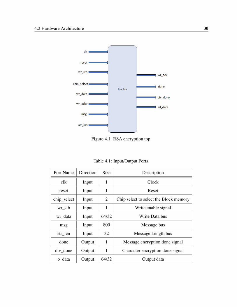


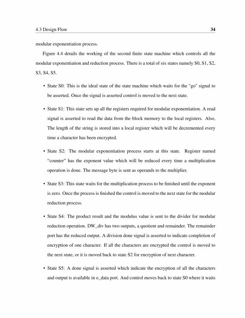
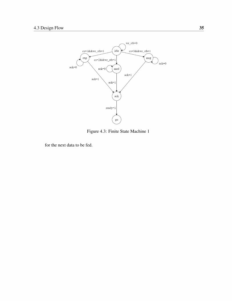
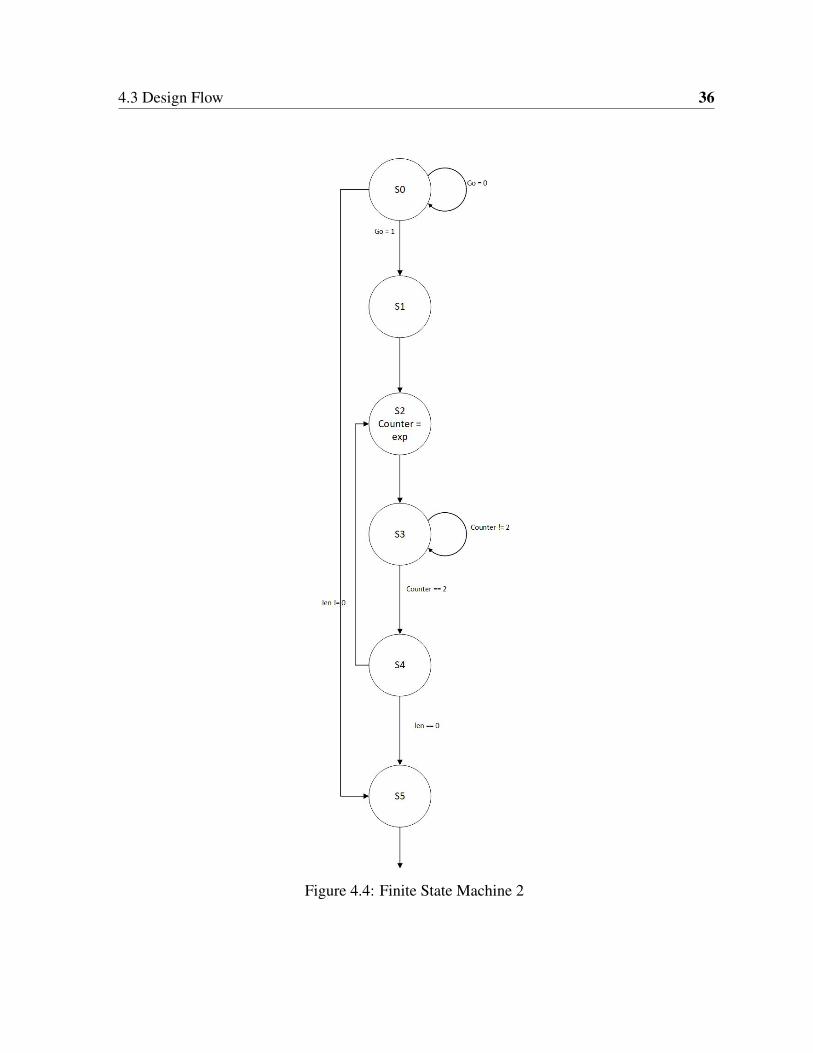


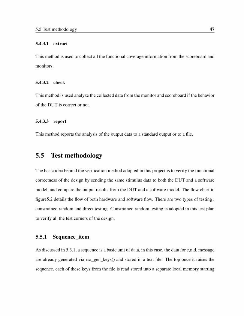
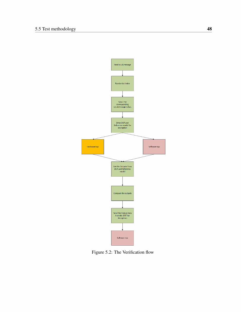


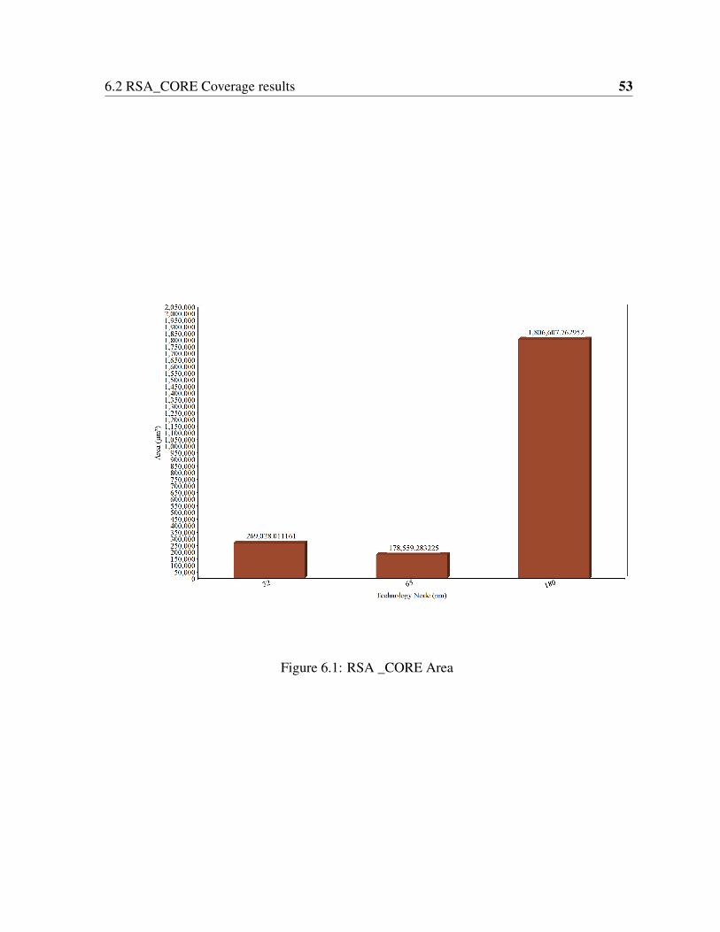


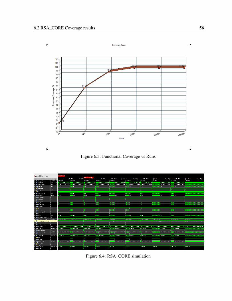

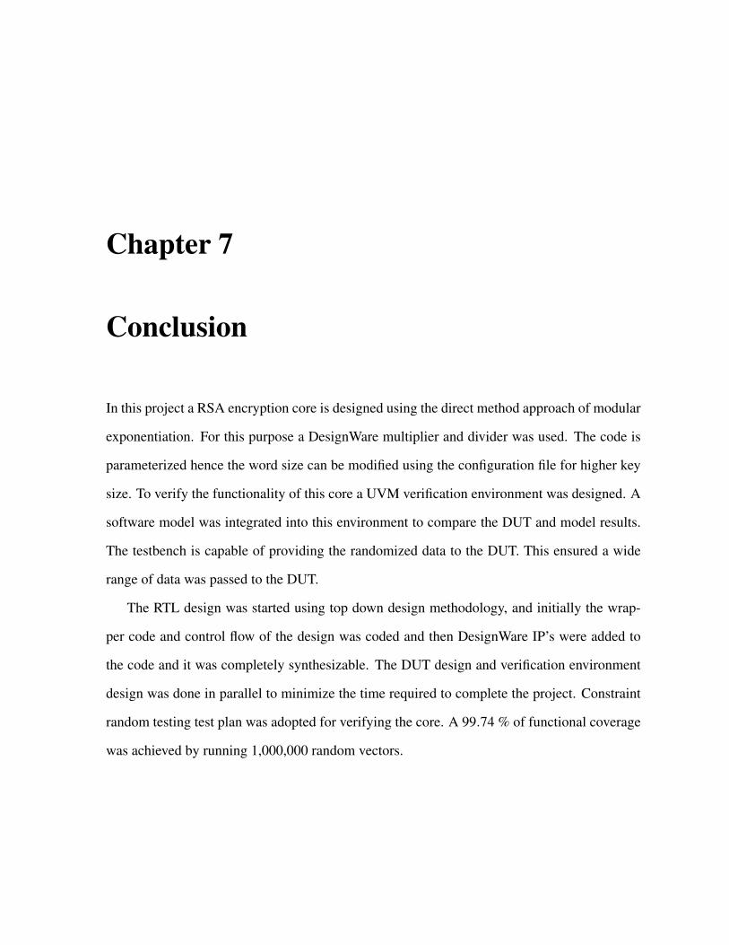


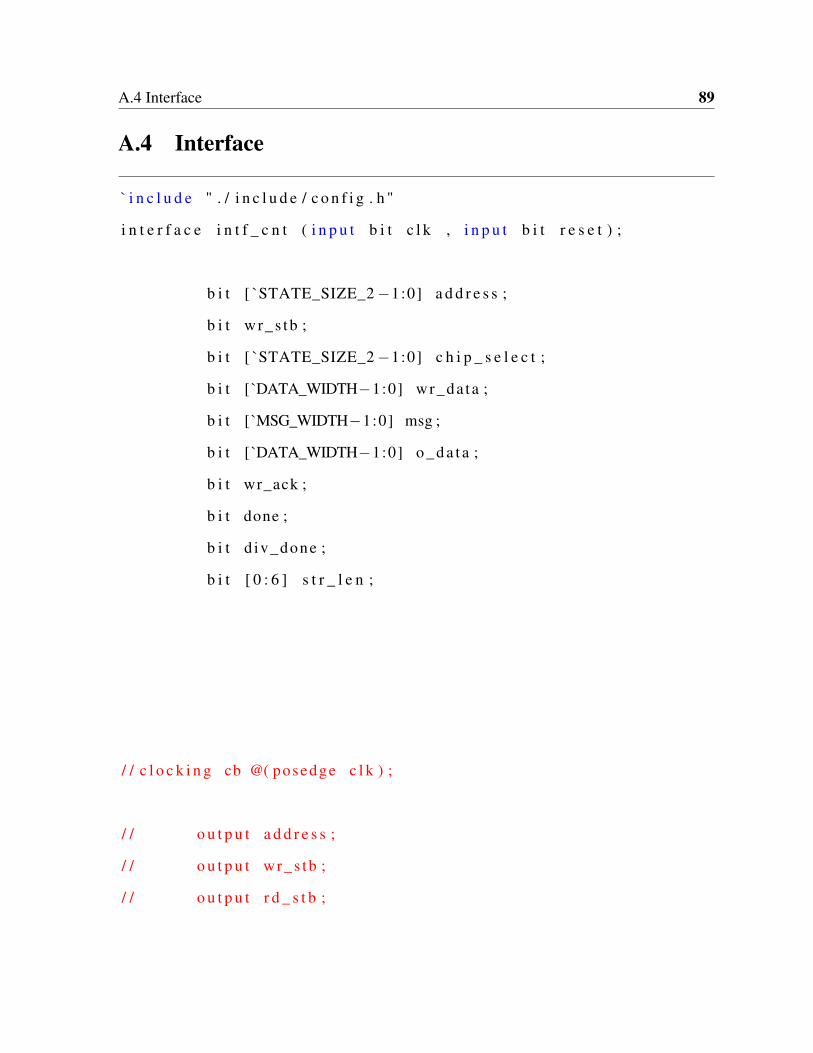
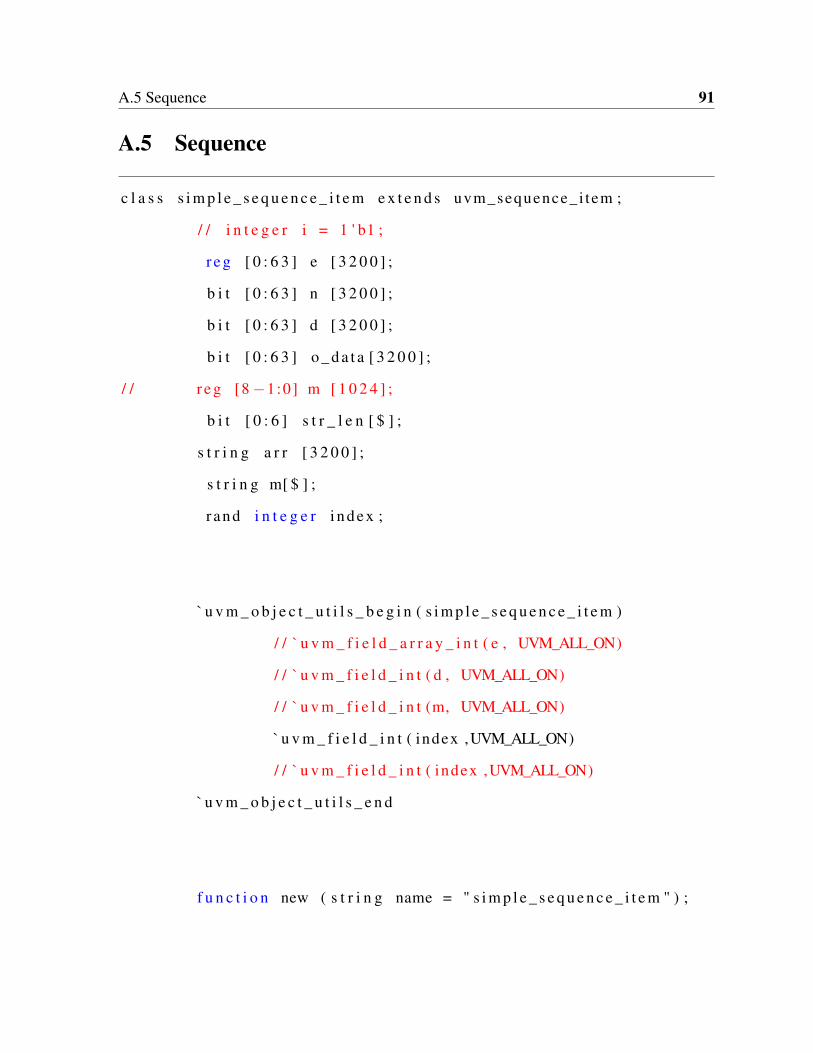
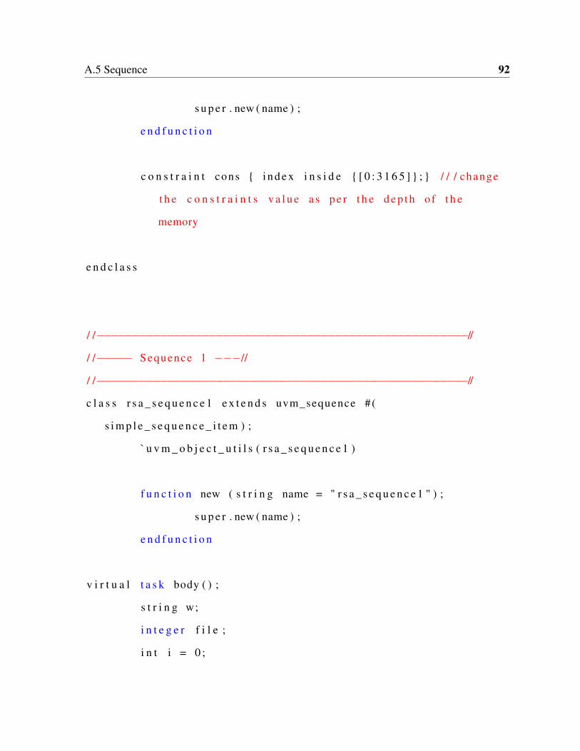


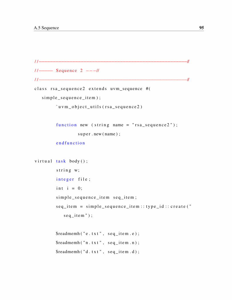


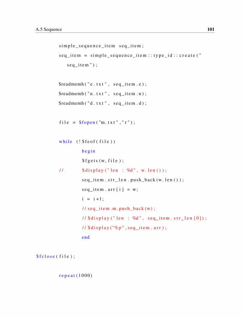


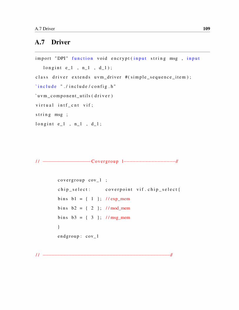
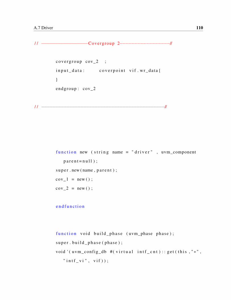


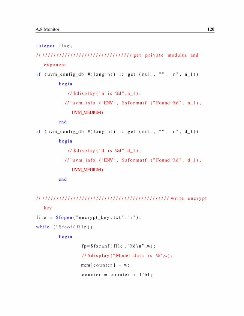


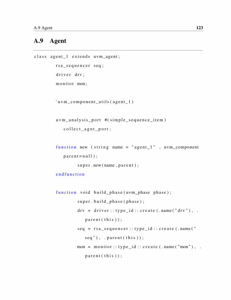
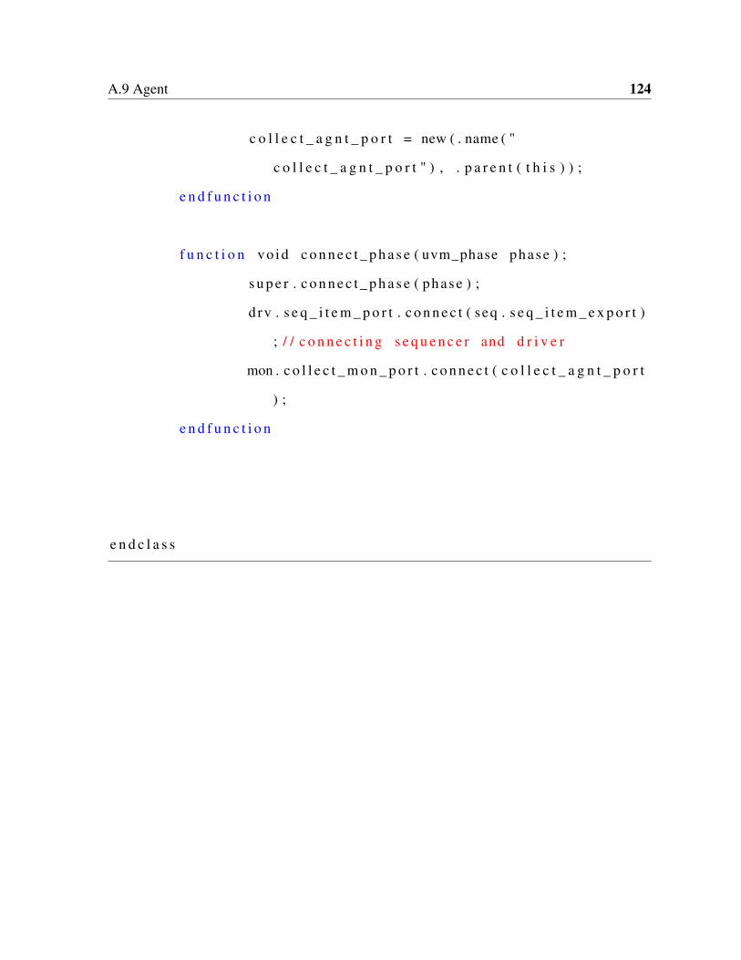
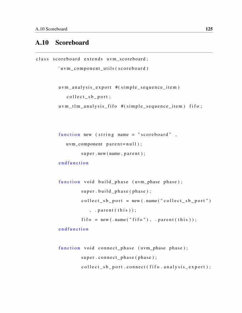
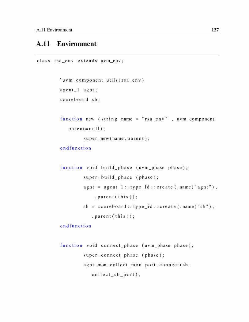

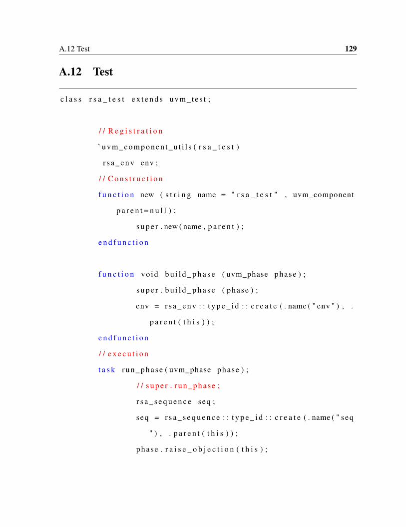


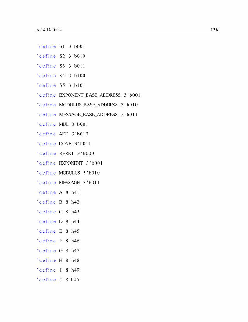


![On the Instantiability of Hash-and-Sign RSA Signaturesdodis/ps/rsa.pdfFull Domain Hash signature scheme (RSA-FDH) [2] and RSA Optimal Asymmetric Encryption Padding scheme (RSA-OAEP)](https://static.documents.pub/doc/80x56/60a7a2da4297302be9762ff2/on-the-instantiability-of-hash-and-sign-rsa-signatures-dodispsrsapdf-full-domain.jpg)