Page 1
DEPARTMENT OF ELECTRICAL
ENGINEERING
INDIAN INSTITUTE OF TECHNOLOGY
MADRAS
CHENNAI-600 036
Functional Verification of RSA Algorithm
A Thesis
Submitted by
RAJAT LABH
EE19M063
For the award of the degree
Of
MASTER OF TECHNOLOGY
June, 2021
Page 3
i
THESIS CERTIFICATE
This is to undertake that the Thesis titled, FUNCTIONAL VERIFICATION OF RSA
ALGORITHM submitted by me to the Indian Institute of Technology Madras, for the
award of M.Tech is a bonafide record of the research work done by me under the
supervision of Prof. V. Kamakoti and Prof. Boby George. The contents of this Thesis,
in full or in parts, have not been submitted to any other Institute or University for the
award of any degree or diploma.
Chennai 600 036
Date:
Rajat Labh
M.Tech(EE)
Prof. V. Kamakoti
Research Guide
Prof. Boby George
Research Co-Guide
© 2021 Indian Institute of Technology Madras
Page 4
ii
ACKNOWLEDGEMENTS
I would want to convey my gratitude to Dr. V. Kamakoti and Dr. Boby George for
their support and encouragement during the project. I am grateful to them for giving
me their time throughout several sessions to discuss project work, which allowed me
to successfully complete this project.
Special thanks to Prof. V. Kamakoti. For allowing me to work on the Shakti Processor
Project, which helped me in better understanding of digital design and
implementation. I owe him a huge debt of gratitude for the VLSI design knowledge I
received during my project work.
I would also want to thank my Mentor, Lavanya Jagan, for explaining the principles
of the Verification Plan and assisting me in understanding the Cocotb-Verilator
verification tools.
My heartfelt gratitude to all of my IIT Madras friends for their unwavering support
and for making my time on campus so joyful and unforgettable.
I also appreciate my family's continual support.
Page 5
iii
ABSTRACT
Cryptography is a means of using codes to protect information and communications
so that only those who are supposed to read and process it may do so. Cryptosystems
encrypt and decrypt data using a set of techniques known as cryptographic algorithms,
or cyphers, to provide secure communications between computer systems, devices,
and applications. Any cryptosystem's core processes are encryption and decryption..
There are numerous encryption and decryption techniques available; the RSA (Rivest-
Shamir-Adlean) algorithm is one of them. Bluespec SystemVerilog has previously
been used to generate the design (BSV). The goal of this project is to create a
verification environment for the RSA design. Cocotb, an open source tool, has also
been discussed.
Page 6
iv
TABLE OF CONTENTS
Title Page
Certificate i
Acknowledgement ii
Abstract iii
Table of Contents iv
List of Tables vi
List of Figures vii
Abbreviations viii
1. Introduction ………………………………………………………………. 1
1.1. Research Goals ………………………………………………………. 3
2. RSA Algorithm …………………………………………………………… 4
2.1 RSA Problem ………………………………………………………..... 4
2.2 Montgomery Modular Multiplication ………………………………… 5
2.3 MMM Algorithm ……………………………………………………… 5
2.4 MMM Architecture ……………………………………………………. 6
2.5 MME Algorithm ………………………………………………………. 8
2.6 MME Architecture …………………………………………………..... 9
3. Cocotb …………………………………………………………….............. 11
3.1 Why use Python ………………………………………………………. 11
3.2 Cocotb Architecture …………………………………………………… 12
3.3 Makefile ………………………………………………………………. 13
3.4 Coroutine ……………………………………………………………… 13
3.5 Trigger ………………………………………………………………… 14
Page 7
v
4. Verification ………………………………………………………………... 15
4.1 Verification Plan ………………………………………………………. 16
4.2 Testbench ……………………………………………………………… 17
4.2.1 Accessing the Design …………………………………………. 17
4.2.2 Assigning Values ……………………………………………… 17
4.2.3 Reading Values ……………………………………………….. 18
4.3 Testbench Architecture ……………………………………………….. 18
4.4 Testbench Components ………………………………………............. 19
4.4.1 Random Input Generator …………………………………….. 19
4.4.2 Driver ……………………………………………………........ 19
4.4.3 Monitor ……………………………………………………….. 19
4.4.4 Scoreboard ………………………………………………......... 19
4.5 Simulation …………………………………………………………….. 20
4.6 Code Coverage ……………………………………………………....... 21
4.7 Result ………………………………………………………………….. 22
5. Conclusion ………………………………………………………………… 23
5.1 Future Work …………………………………………………………... 23
References 24
Page 8
vi
LIST OF TABLES
Table 1.1: Security objectives
Table 4.1: Verification Plan
Table 4.2: Coverage Report
Page 9
vii
LIST OF FIGURES
Figure 2.1: Architecture PE
Figure 2.2: Architecture qPE
Figure 2.3: Architecture MMM
Figure 2.4: Architecture MME
Figure 3.1: cocotb Architecture
Figure 3.2: Makefile
Figure 4.1: Testbench Architecture
Figure 4.2: Simulation Result
Figure 4.3: Coverage Result
Page 10
viii
ABBREVIATIONS
RSA Rivest, Shamir, Adleman
MIT Massachusetts Institute of Technology
MMM Montgomery Modular Multiplication
MME Montgomery Modular Exponentiation
PE Processing Element
COCOTB COroutine based COsimulation TestBench
OOP Object Oriented Programming
UVM Universal Verification Methodology
DUT Device Under Test
RTL Register Transfer Logic
VPI Verilog Procedural Interface
VHPI VHDL Procedural Interface
IC Integrated Chip
VLSI Very Large Scale Integration
CAD Computer Aided Design
BSV Bluespec System Verilog
Page 11
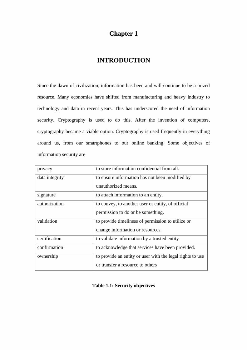
Chapter 1
INTRODUCTION
Since the dawn of civilization, information has been and will continue to be a prized
resource. Many economies have shifted from manufacturing and heavy industry to
technology and data in recent years. This has underscored the need of information
security. Cryptography is used to do this. After the invention of computers,
cryptography became a viable option. Cryptography is used frequently in everything
around us, from our smartphones to our online banking. Some objectives of
information security are
privacy to store information confidential from all.
data integrity to ensure information has not been modified by
unauthorized means.
signature to attach information to an entity.
authorization to convey, to another user or entity, of official
permission to do or be something.
validation to provide timeliness of permission to utilize or
change information or resources.
certification to validate information by a trusted entity
confirmation to acknowledge that services have been provided.
ownership to provide an entity or user with the legal rights to use
or transfer a resource to others
Table 1.1: Security objectives
Page 12
2
Cryptography's key processes are encryption and decryption. The technique of
encoding common data, also known as "plain-text," is known as encryption. It is done
in such a way that only authorised users have access to the information it contains.
"Cipher-text" is another term for the encoded data. The process of translating cypher
text to plain text is known as decryption. The "key" is the most important component
of this procedure.
A key is a little piece of data that determines a cryptographic algorithm's output. A
key can be made in a variety of ways. It should be a random number that is difficult to
predict. Pseudorandom number generators and random-number generators are two of
the most well-known key generators. Random number generators generate random
numbers on their own, but pseudo-random number generators require a seed value. To
produce a new set of random numbers, adjust the seed values. The ability to renew the
random number if the seed value is known is one downside of this pseudo-random
generator.
The complexity of prime factor decomposition of a large number is used to determine
the security level of RSA, which is a common public key cryptography technique.
Three MIT cryptography scientists, Ron Rivest, Adi Shamir, and Leonard Adleman,
suggested it in 1978, and ISO formally adopted it as an International Standard in
1992. Compared with the symmetric key cryptographic algorithms, RSA algorithm
mainly has two distinct advantages:
1. It supports for digital signatures and digital certificates.
2. It simplifies the work of key management.
Page 13
3
1.2 RESEARCH GOALS
The goal is to build a verification environment that verifies the RSA encryption
algorithm. Cocotb-Verilator has been used for Verification. The goals achieved with
the following objectives:
• To understand the RSA encryption algorithm for 2048 bit key length.
• To apply an open source verification technique to create the verification
environment.
• To generate the results with coverage tests.
Page 14
Chapter 2
RSA ALGORITHM
Rivest, Shamir, and Adleman invented the first successful public-key encryption
scheme in 1978, which is now known as RSA. The RSA scheme is based on a
challenging mathematical problem: factoring huge integers. The use of a tough
mathematical problem in cryptography re-energized efforts to create more efficient
factoring algorithms.
The most widely used public-key cryptography algorithm is RSA. It's utilised in
public signature apps and secure transactions in general. It provides effective
cryptographic security, but it is slower than symmetric key methods due to its difficult
mathematical calculation complexity.
2.1 RSA PROBLEM
Given a positive integer 𝑛 that is a product of two distinct odd primes 𝑝 and 𝑞, a
positive integer 𝑒 such that gcd(𝑒, (𝑝 − 1)(𝑞 − 1)) = 1, and an integer 𝑐, find an
integer 𝑚 such that 𝑚 = 𝑐𝑒 (𝑚𝑜𝑑 𝑛).
In other words, the RSA problem is that of finding 𝑒𝑡ℎ roots modulo a composite
integer 𝑛. The conditions imposed on the problem parameters 𝑛 and 𝑒 ensure that for
Page 15
5
each integer 𝑐 ∈ {0,1, . . . , 𝑛 − 1} there is exactly one 𝑚 ∈ {0,1, . . . , 𝑛 − 1} such that
𝑚 = 𝑐𝑒 (𝑚𝑜𝑑 𝑛).
2.2 MONTGOMERY MODULAR MULTIPLICATION
The RSA algorithm's mathematics may be summed up in two operations: modular
multiplication and modular exponentiation. Modular multiplication has a significant
disadvantage. Trial division is used to obtain the remaining value. There have been
numerous attempts to break down the trial division barrier. The Montgomery Modular
Multiplication (MMM) and Montgomery Modular Exponentiation (MME) algorithms,
first described by P. Montgomery, are the most often used solutions. By normalising
the values to be multiplied, this technique manages to fully avoid trial division.
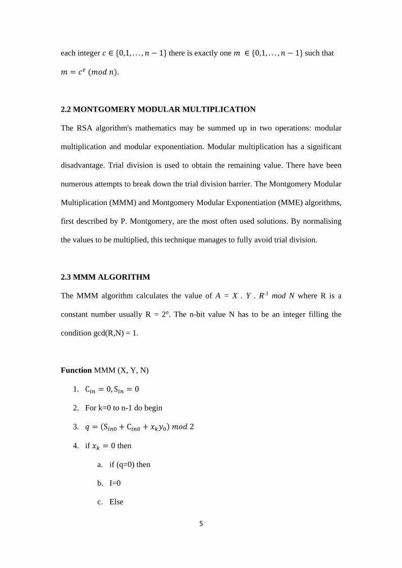
2.3 MMM ALGORITHM
The MMM algorithm calculates the value of A = X . Y . R-1 mod N where R is a
constant number usually R = 2n. The n-bit value N has to be an integer filling the
condition gcd(R,N) = 1.
Function MMM (X, Y, N)
1. C𝑖𝑛 = 0, S𝑖𝑛 = 0
2. For k=0 to n-1 do begin
3. 𝑞 = (S𝑖𝑛0 + C𝑖𝑛0 + 𝑥𝑘𝑦0) 𝑚𝑜𝑑 2
4. if 𝑥𝑘 = 0 then
a. if (q=0) then
b. I=0
c. Else
Page 16
6
d. I=N
e. End
5. End
6. if 𝑥𝑘 = 1 then
a. if (q=0) then
b. I=Y
c. Else
d. I=Y+N
e. End
7. End
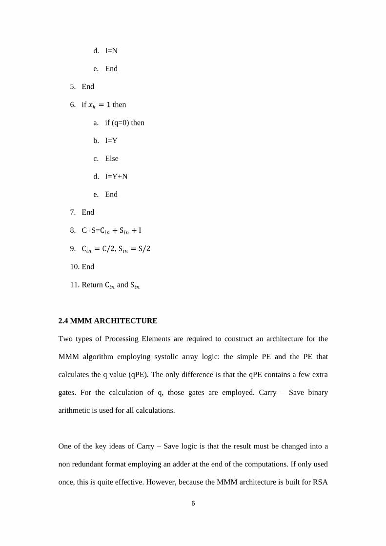
8. C+S=C𝑖𝑛 + S𝑖𝑛 + I
9. C𝑖𝑛 = C/2, S𝑖𝑛 = S/2
10. End
11. Return C𝑖𝑛 and S𝑖𝑛
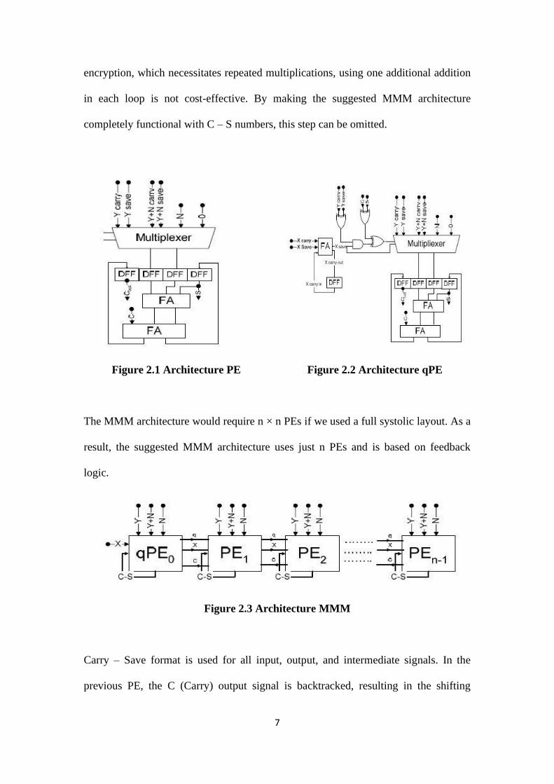
2.4 MMM ARCHITECTURE
Two types of Processing Elements are required to construct an architecture for the
MMM algorithm employing systolic array logic: the simple PE and the PE that
calculates the q value (qPE). The only difference is that the qPE contains a few extra
gates. For the calculation of q, those gates are employed. Carry – Save binary
arithmetic is used for all calculations.
One of the key ideas of Carry – Save logic is that the result must be changed into a
non redundant format employing an adder at the end of the computations. If only used
once, this is quite effective. However, because the MMM architecture is built for RSA
Page 17
7
encryption, which necessitates repeated multiplications, using one additional addition
in each loop is not cost-effective. By making the suggested MMM architecture
completely functional with C – S numbers, this step can be omitted.
Figure 2.1 Architecture PE Figure 2.2 Architecture qPE
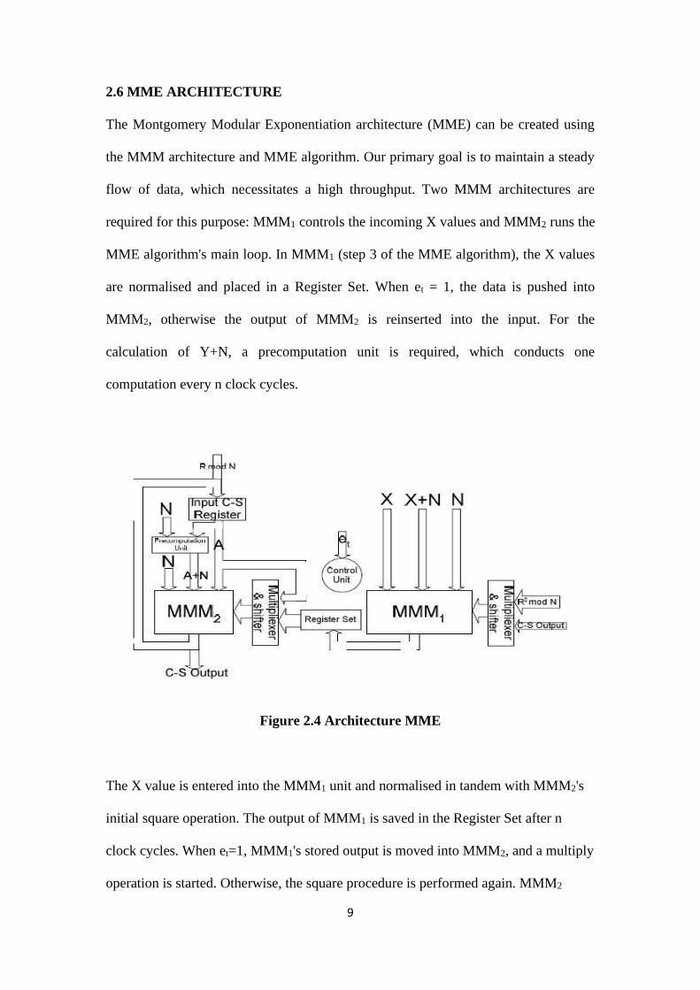
The MMM architecture would require n × n PEs if we used a full systolic layout. As a
result, the suggested MMM architecture uses just n PEs and is based on feedback
logic.
Figure 2.3 Architecture MMM
Carry – Save format is used for all input, output, and intermediate signals. In the
previous PE, the C (Carry) output signal is backtracked, resulting in the shifting
Page 18
8
(division by 2 operation) in step 9 of the MMM algorithm. After n clock cycles, the
suggested MMM architecture produces a result.
2.5 MME ALGORITHM
The distinctiveness of MMM algorithm is that it uses the R value and calculates
A = X . Y . R-1 mod N. The algorithm for Montgomery Modular Exponentiation
(MME) is
Function MME (X, e, N)
1. 𝐴 = 𝑅 𝑚𝑜𝑑 𝑁
2. 𝐺 = 𝑅2 𝑚𝑜𝑑 𝑁
3. �̅� = 𝑀𝑀𝑀(𝑋, 𝐺)
4. For i=t to 0 do begin
a. 𝐴 = 𝑀𝑀𝑀(𝐴, 𝐴)
b. If e𝑖 = 1 then 𝐴 = 𝑀𝑀𝑀(𝐴, �̅�)
5. End
6. 𝐴 = 𝑀𝑀𝑀(𝐴, 1)
R=2n, e is the exponent, and all numbers are in Carry – Save format. Regardless of the
X or e value, steps 1 and 2 are the same. They can be computed ahead of time. The
value in step 3 only needs to be computed once for each X before being saved in a
memory module. When the i-th bit of e is set, step 4b is completed.
Page 19
9
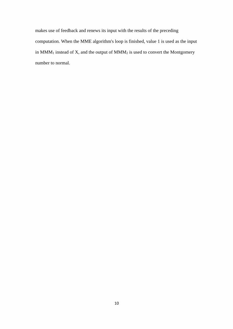
2.6 MME ARCHITECTURE
The Montgomery Modular Exponentiation architecture (MME) can be created using
the MMM architecture and MME algorithm. Our primary goal is to maintain a steady
flow of data, which necessitates a high throughput. Two MMM architectures are
required for this purpose: MMM1 controls the incoming X values and MMM2 runs the
MME algorithm's main loop. In MMM1 (step 3 of the MME algorithm), the X values
are normalised and placed in a Register Set. When et = 1, the data is pushed into
MMM2, otherwise the output of MMM2 is reinserted into the input. For the
calculation of Y+N, a precomputation unit is required, which conducts one
computation every n clock cycles.
Figure 2.4 Architecture MME
The X value is entered into the MMM1 unit and normalised in tandem with MMM2's
initial square operation. The output of MMM1 is saved in the Register Set after n
clock cycles. When et=1, MMM1's stored output is moved into MMM2, and a multiply
operation is started. Otherwise, the square procedure is performed again. MMM2
Page 20
10
makes use of feedback and renews its input with the results of the preceding
computation. When the MME algorithm's loop is finished, value 1 is used as the input
in MMM1 instead of X, and the output of MMM2 is used to convert the Montgomery
number to normal.
Page 21
Chapter 3
COCOTB
Cocotb is a Python-based COroutine-based COsimulation TestBench for testing
VHDL and SystemVerilog RTL. It is necessary to use a simulator to simulate the
design. It's been tested with a wide range of simulators on Linux, Windows, and
macOS. It follows the same design reuse and randomised testing concept as UVM.
Unlike UVM, it is written in Python. It provides a verification alternative to Verilog,
System Verilog, or the VHDL framework.
3.1 WHY USE PYTHON
HDL is great for designing hardware or firmware. But hardware design and
verification are different problems. It might not be optimal using the same language
for hardware design and verification. Verification testbenches are software, not
hardware. Higher level languages concepts, like OOP, are useful when writing
complex testbenches.
SystemVerilog approach has simulation-only OOP features. UVM libraries are
written in SystemVerilog. SystemVerilog is a very complicated language. It has 221
keywords. It is very powerful but takes significant amount of time to learn. UVM also
has similar complexity issues. It has over 300 classes. It is also very powerful, but
very difficult to get started.
Page 22
12
Python, on the other hand, is simple and easy to learn. It is also very powerful
language. It has a large standard library and a huge ecosystem. Python is well
documented, popular and lots of resources are available.
3.2 COCOTB ARCHITECTURE
Design under test (DUT) runs in standard simulator. It Is instantiated as the toplevel in
the simulator. Cocotb provides interface between simulator and Python. It drives the
stimulus onto the inputs to the DUT. It also monitors the output directly from Python.
It uses Verilog Procedural Interface (VPI) or VHDL Procedural Interface (VHPI).
Figure 3.1 cocotb Architecture
Python test is a simple python function referred to as coroutines. Python testbench
code can:
• Reach into DUT hierarchy and change values.
• Wait for simulation time to pass.
• Wait for a rising or falling edge of a signal.
Page 23
13
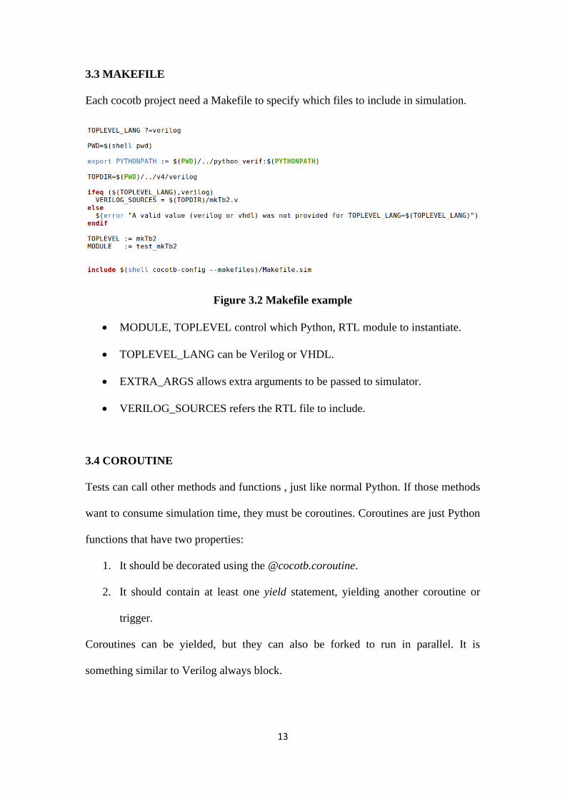
3.3 MAKEFILE
Each cocotb project need a Makefile to specify which files to include in simulation.
Figure 3.2 Makefile example
• MODULE, TOPLEVEL control which Python, RTL module to instantiate.
• TOPLEVEL_LANG can be Verilog or VHDL.
• EXTRA_ARGS allows extra arguments to be passed to simulator.
• VERILOG_SOURCES refers the RTL file to include.
3.4 COROUTINE
Tests can call other methods and functions , just like normal Python. If those methods
want to consume simulation time, they must be coroutines. Coroutines are just Python
functions that have two properties:
1. It should be decorated using the @cocotb.coroutine.
2. It should contain at least one yield statement, yielding another coroutine or
trigger.
Coroutines can be yielded, but they can also be forked to run in parallel. It is
something similar to Verilog always block.
Page 24
14
3.5 TRIGGER
When design and testbench are simulated independently, it is called cosimulation.
Triggers are represented as communication through VPI or VHPI interfaces. When
Python code is executing, simulation time is not advancing. When a trigger is yielded,
the testbench waits until the triggered condition is satisfied before resuming
execution.
There are few triggers available in cocotb
• Timer (time, unit): it waits for certain amount of simulation time to pass.
• Edge (signal): it waits for a signal to change state ( rising or falling edge ).
• RisingEdge (signal): it waits for the rising edge of a signal.
• FallingEdge (signal): it waits for the falling edge of a signal.
• ClockCycles (signal, num): it waits for some number of clocks (transition
from 0 to 1).
Page 25
Chapter 4
VERIFICATION
Electronics equipment and gadgets have become far more functional, but their
physical sizes and weights have shrunk dramatically. The main reason is because
significant improvements in integration technologies have made it possible to
fabricate millions of transistors in a single Integrated Circuit (IC) or chip. In a VLSI
IC, systems of systems can be implemented. However, as the functionality of VLSI
ICs has increased, the design problem has grown enormously complex.
Following the design parameters, all subsequent procedures are automated using CAD
tools. Even designs created with CAD technologies, however, may contain flaws. As
a result, a technique to check whether the design fits all of the input specifications is
required. Verification is the term for this method.
From a functional standpoint, functional verification is described as the process of
ensuring that an RTL (Synthesizable Verilog, VHDL, SystemVerilog) design fits its
specifications. It verifies that the design under test (DUT) correctly implements the
specification's functionality.
Page 26
16
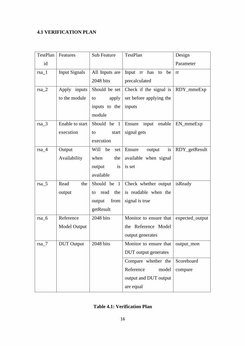
4.1 VERIFICATION PLAN
TestPlan
id
Features Sub Feature TestPlan Design
Parameter
rsa_1 Input Signals All Inputs are
2048 bits
Input rr has to be
precalculated
rr
rsa_2 Apply inputs
to the module
Should be set
to apply
inputs to the
module
Check if the signal is
set before applying the
inputs
RDY_mmeExp
rsa_3 Enable to start
execution
Should be 1
to start
execution
Ensure input enable
signal gets
EN_mmeExp
rsa_4 Output
Availability
Will be set
when the
output is
available
Ensure output is
available when signal
is set
RDY_getResult
rsa_5 Read the
output
Should be 1
to read the
output from
getResult
Check whether output
is readable when the
signal is true
isReady
rsa_6 Reference
Model Output
2048 bits Monitor to ensure that
the Reference Model
output generates
expected_output
rsa_7 DUT Output 2048 bits Monitor to ensure that
DUT output generates
output_mon
Compare whether the
Reference model
output and DUT output
are equal
Scoreboard
compare
Table 4.1: Verification Plan
Page 27
17
The verification method used in this project is to ensure that the design is functionally
valid. It's done by giving the DUT and the Reference Model the same stimulus. The
output of the DUT is then compared to the output of the Reference Model.
4.2 TESTBENCH
A “testbench” is the code used to create a determined input sequence to a design and
then observe the response. The design is usually written in Verilog, SystemVerilog,
VHDL.
4.2.1 ACCESSING THE DESIGN
Cocotb identifies the toplevel instantiation in the simulator and produces a handle
named dut when it initialises. The “dot” notation, which is used in Python to access
object attributes, may be used to access toplevel signals. Signals inside the design can
be accessed using the same approach.
clk = dut.clk - a reference to the “clk” signal
4.2.2 ASSIGNING VALUES
The value attribute of a handle object or direct assignment while traversing the
hierarchy can both be used to assign values to signals.
clk.value = 1 - to assign a value to “clk” signal
Page 28
18
4.2.3 READING VALUES
The value property of a handle object can be used to access values in the DUT. A
common blunder is overlooking the .value parameter, which only returns a handle
reference (helpful for defining an alias name), not the value.
count = dut.counter.value - read a value back from the DUT
4.3 TESTBENCH ARCHITECTURE
Figure 4.1: Testbench Architecture
Page 29
19
4.4 TESTBENCH COMPONENTS
4.4.1 RANDOM INPUT GENERATOR
Random input Generator is the Test Sequence Generator. It is used to initialise the
verification environment and the DUT.
4.4.2 BUS
Simply put, a bus is a collection of signals. The Bus class also accepts a list of signal
names or a dictionary mapping attribute names to signal names. Values can be
programmed onto buses. In the Driver class, there is a specific bus implementation.
4.4.3 DRIVER
Driver communicates with the DUT via VPI or VHPI. It fetches the data from
Sequence Generator and drive the data to DUT.
4.4.3 MONITOR
The monitor is used to detect DUT output signals. The Monitor class is a foundation
class from which you must derive your own classes for your own needs. Monitors are
useful for both the DUT's outputs for verification and the DUT's inputs for driving a
test model of the DUT that can be compared to the actual DUT. Expected transactions
are frequently generated by this model, which are then compared using the
Scoreboard class.
4.4.4 SCOREBOARD
Comparison of expected output and actual output is performed by Scoreboard.
Expected output is the output from Reference Model. The output from the DUT is the
Page 30
20
actual output. By providing a monitor and an expected output queue, we can add
interfaces. To add an interface to the scoreboard, use the add_interface method.
4.5 SIMULATION
Figure 4.2: Simulation Result
Page 31
21
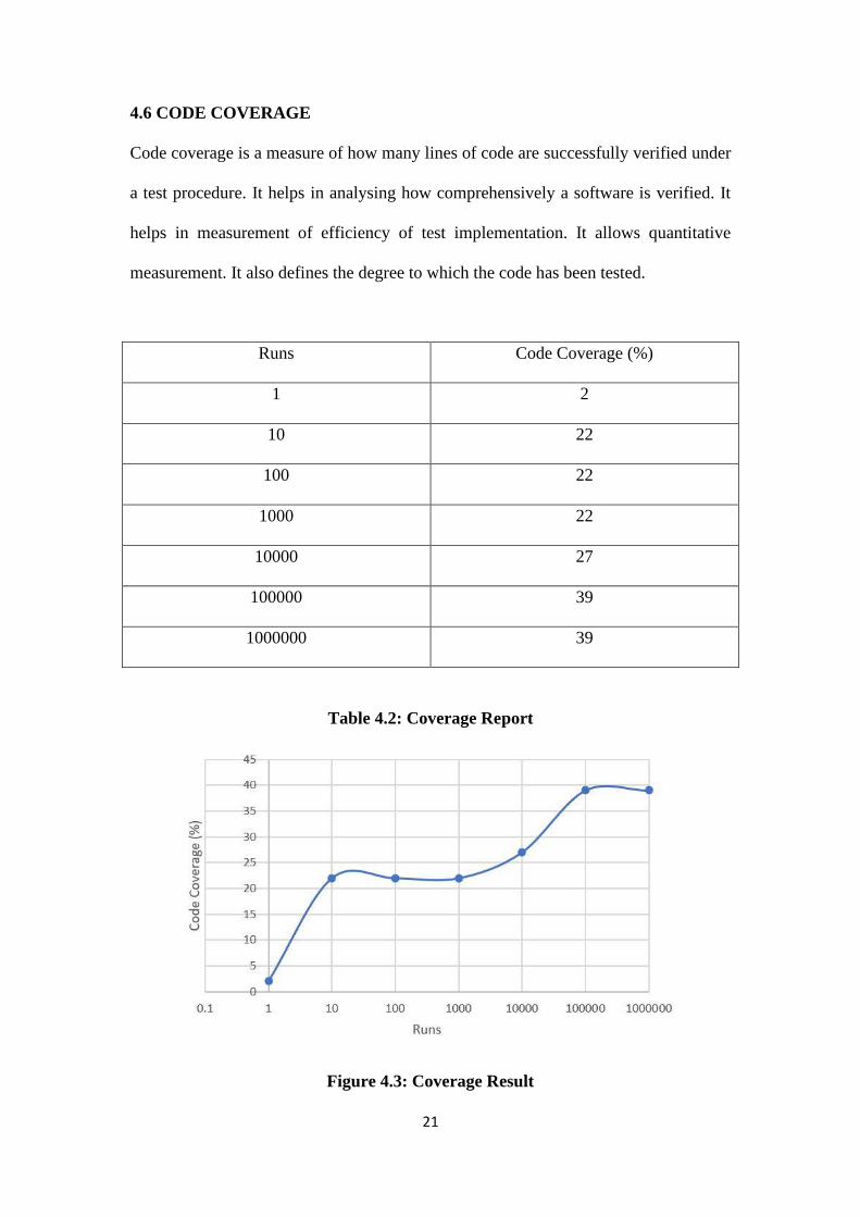
4.6 CODE COVERAGE
Code coverage is a measure of how many lines of code are successfully verified under
a test procedure. It helps in analysing how comprehensively a software is verified. It
helps in measurement of efficiency of test implementation. It allows quantitative
measurement. It also defines the degree to which the code has been tested.
Runs Code Coverage (%)
1 2
10 22
100 22
1000 22
10000 27
100000 39
1000000 39
Table 4.2: Coverage Report
Figure 4.3: Coverage Result
Page 32
22
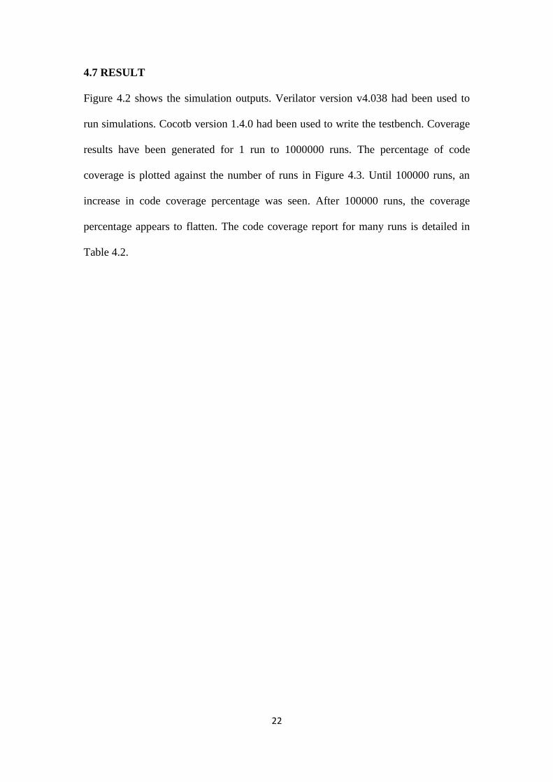
4.7 RESULT
Figure 4.2 shows the simulation outputs. Verilator version v4.038 had been used to
run simulations. Cocotb version 1.4.0 had been used to write the testbench. Coverage
results have been generated for 1 run to 1000000 runs. The percentage of code
coverage is plotted against the number of runs in Figure 4.3. Until 100000 runs, an
increase in code coverage percentage was seen. After 100000 runs, the coverage
percentage appears to flatten. The code coverage report for many runs is detailed in
Table 4.2.
Page 33
Chapter 5
CONCLUSION
The RSA algorithm has been implemented based on Montgomery Modular
Exponentiation. The design has been created using Bluespec SystemVerilog (BSV).
The code has been designed for 2048 bit. It can be further modified for higher key
size. A cocotb verification environment was designed to verify the functionality of
the design. A Python based software reference model was integrated into this cocotb
environment to compare the model and DUT results. The testbench is efficient to
provide large number of randomized data to the DUT. It ensured that a wide range of
data had been passed to DUT.
5.1 FUTURE WORK
Modular Exponentiation technique has been implemented in this design. Other
techniques can be implemented and merits can be compared. Modular exponentiation
can be explored more for higher key sizes.
Page 34
24
REFERENCES
[1] Peter L. Montgomery. Modular multiplication without trial division. In
Mathematics of Computation, Vol. 44, No. 170. (Apr., 1985), pp. 519-521.,
1985.
[2] A. P. Fournaris and O. Koufopavlou. A New RSA Encryption Architecture and
Hardware Implementation based on Optimized Montgomery Multiplication. In
International Symposium on Circuits and Systems (ISCAS 2005), 23-26 May
2005, Kobe, Japan.
[3] https://readthedocs.org/projects/cocotb/