Design Approach, Experience and Results of 1MW Solar Thermal Power Plant Solar Thermal Power Plant and Testing Facility Project funded by Ministry of New and Renewable Energy, GoI, New Delhi Prof. j k nayak, prof. rangan banerjee, prof. Shireesh Kedare, Prof. Santanu bandopadhyay, Department of energy science and engineering, IIT Bombay, mumbai 400076, india www.ese.iitb.ac.in 1
Transcript
Design Approach, Experience and Results of 1MW Solar Thermal Power Plant
Solar Thermal Power Plant and Testing Facility Project funded by
Ministry of New and Renewable Energy, GoI, New Delhi
Prof. j k nayak, prof. rangan banerjee, prof. Shireesh Kedare, Prof. Santanu bandopadhyay,
Department of energy science and engineering, IIT Bombay, mumbai 400076, india
www.ese.iitb.ac.in
1
Concept/Objectives
0% 100 %
Completely
Indigenous
Import Complete plant
Prototype
• 1MW Solar Thermal Power Plant- Design & Development of a 1 MW plant. - Generation of Electricity for supply to the grid.
• National Test Facility- Development of facility for component testing and characterization.- Scope of experimentation for the continuous development of technologies.
• Development of Simulation Package- Simulation software for scale-up and testing.- Compatibility for various solar applications.
Project funded by Ministry of New and Renewable Energy, New Delhi @ Solar Energy Centre (SEC), Gwal Pahari, Haryana
50 %
National Test Facility
2
Role of IIT Bombay• Design of solar thermal power plant of 1MWe capacity
– Plant configuration designed by IITB– Turbine selection, study of its characteristics by IITB– Storage design and operating strategy conceived by IITB– Heat exchanger design and operating strategy conceived by IITB– Design of controls conceived, detailed and executed by IITB
• Engineering of solar thermal power plant – By IITB with some support from TCE, L and T and other experts
• Procurement for solar thermal power plant – As per IIT Bombay’s procedure through different vendors
• Design and installation of Testing Facility by IITB• Development and testing of simulation package by IITB• Organizational structure
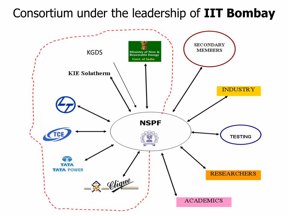
– Consortium under the leadership of IIT Bombay– Team of engineers and managers at IIT Bombay– Team of professors from IITB across different departments
3
4
Consortium under the leadership of IIT Bombay
KGDS
Plant configuration design• Use of widely used thermodynamic cycle
– 40 bar 350°C steam Rankine cycle
– 1 MW (Mega Watt range)
• Combination of low and high cost solar concentrators– Site and technology specific
– Design DNI 600 W/sqm !! Near Delhi !!
– Minimum temperature requirement, characteristics of concentrators available, sizing
– Technologies available locally: Advantage of low cost and local technical support
– Technologies available globally: Advantage of experience
– Procured through open tender process under specifications prepared by IIT Bombay
5
Preheater Steam Generator
Super-Heater
6
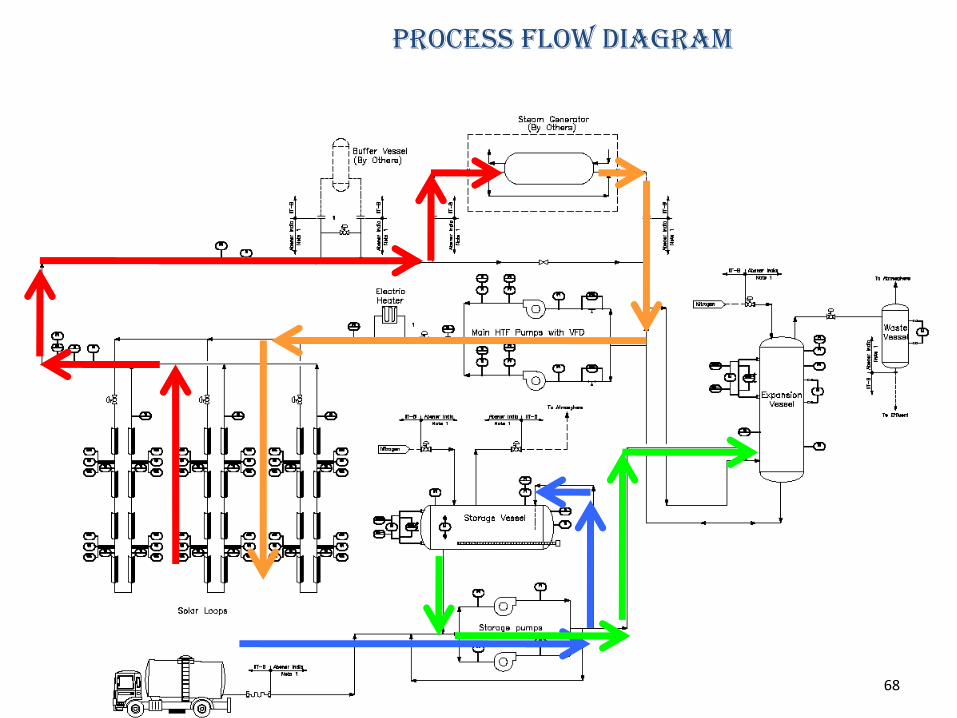
Schematic of process flow for the solar thermal power plant
Process flow diagram
PTC field loop 3 MWth
Without storageSupplied by Abener
LFR field loop 2 MWth
Direct steam generationSupplied by KGDS Renewables
High temp short time storage and Hx designed by IIT with L and T
Turbine and generator block (1 Mwe) supplied by MaxwattBalance of plant designed and procured by IIT Bombay
7
Turbine, storage and Hx: Operating strategy and controls
• Willans’ line for turbine
• Performance of plant at low radiation
• Design of Hx
• Operating strategy for Hx
• Sizing of HT storage tank
• Operating strategy for HT storage tank
9
0
100
200
300
400
500
600
700
800
900
1000
1100
1200
0 0.1 0.2 0.3 0.4 0.5 0.6 0.7 0.8 0.9 1 1.1 1.2
Oil Flow Rate 2.7 kg/s
Oil Flow Rate 3.7 kg/s
Oil Flow Rate 4.7 kg/s
Oil Flow Rate 6.2 kg/s
Oil Flow Rate 7 kg/s
Oil Flow Rate8.1 kg/s
Oil Flow Rate 9.38 kg/s
LFR Flow Rate (kg/s)
Po
wer
(kW
)
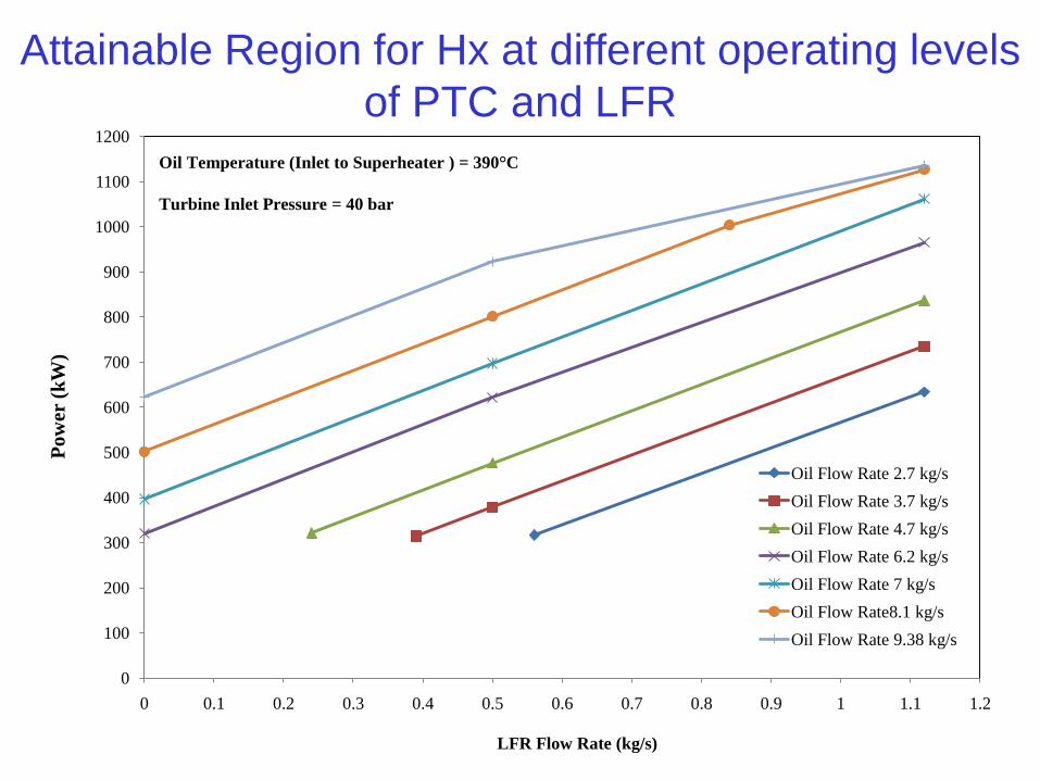
Oil Temperature (Inlet to Superheater ) = 390°C
Turbine Inlet Pressure = 40 bar
Attainable Region for Hx at different operating levels
of PTC and LFR
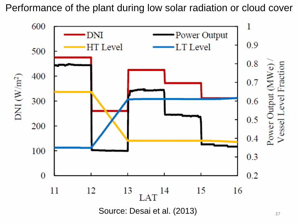
Performance of the plant during low solar radiation or cloud cover
Source: Desai et al. (2013) 37
• Starting up strategy: Starting auxiliaries, without auxiliary fuel• Operate Hx at desired level to get turbine-acceptable conditions with
flow rates from two solar fields under given solar radiation • to effect continuous power generation from T-G unit• The minimum power level at which the turbine should be
operated: 250 kW• For safety, minimum power level : 320 kW
• Control HT vessel flow rates when the radiation drops to a level which is too low • oil will be withdrawn from the high temperature (HT) vessel until
the higher radiation level is achieved• or the oil level in the HT vessel reaches the minimum (20%) value.
• Plant shutdown: when HT vessel level reaches minimum and the radiation is not enough to run the plant at a minimum rating
• When radiation is good: Charge storage
Control Philosophy and operating strategy
38
Plant layoutAt SEC, Gwal PahariAbout 13 Acres Test facility on 0.46 AcresPTC: 8075 sq.mon 6.348 AcresLFR: 7020 sq.mOn 2.968 AcresPower Block on 1.544 AcresFree area in between1.503 Acres 39
Site preparation, Land leveling
42
Turbine Deck Foundation
48
49
51
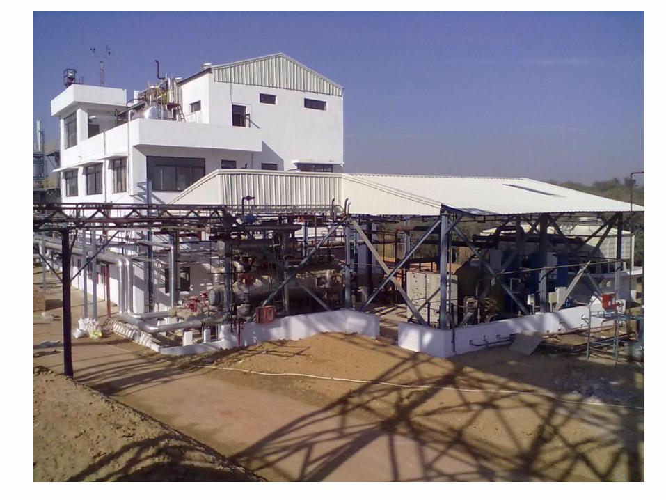
Arial view of
1 MW Solar Thermal Power plant And Test Facility by IIT Bombay
at Solar Energy Centre (SEC), Gwal Pahari, Dist Gurgaon, Haryana
Solar Thermal Power Plant and Testing Facility Project funded by Ministry of New and Renewable Energy, GoI, New Delhi52
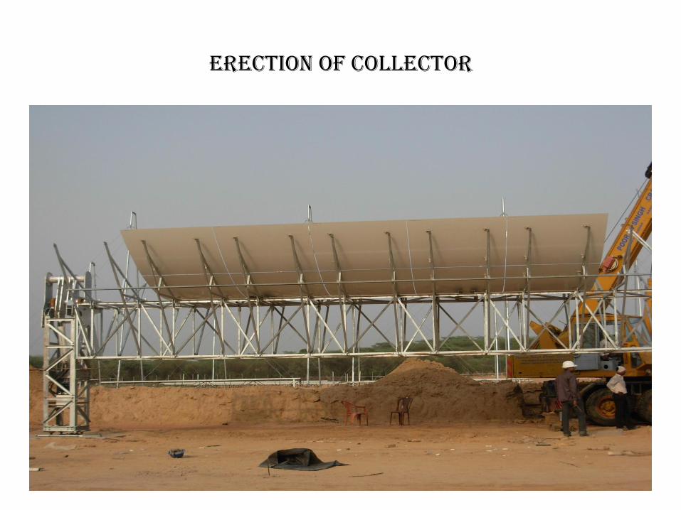
PARABOLIC TROUGH SOLAR FIELD
53
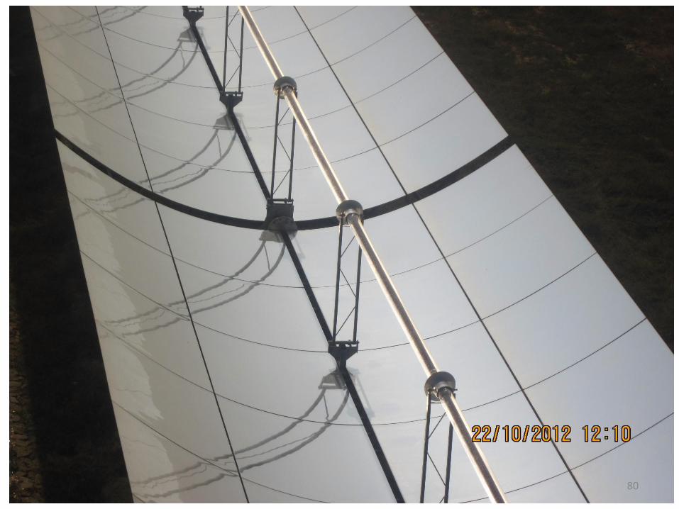
Parabolic trough solar field
• Mirror
• Receiver Tubes
• Structure
• Tracking mechanism
• Heat Transfer Fluid
• Pressure Vessels
• Piping
54
Erection of Collector
63
Title
Description
Process Flow Diagram
68
Incorporating Storage Vessel
• 30 minutes storage at minimum turbine load (320 kW) : Designed by IIT B
– Incorporating HT tank pump
• Nitrogen blanketing and pressurization:
– Equalization line between HT and LT vessel
– Novel control strategy to minimize consumption of Nitrogen
69
72
Dirty water coming from headers Charging N2 Filling Oil
Cleaning the lines Pressure testing Chemical treatment
Plant Commissioning
Charging into storage tank
76
77
Expansion vessel piping from Storage vessel
Parabolic Trough Solar Field
79
80
LINEAR FRESNEL REFLECTOR
81
An artistic view of LFR system
82
Reflector base A – frame baseSide stay wire base
A – frame
Receiver
Stay wire
Reflector
Reflector base support
LFR Solar field components by KGDS Renewables
84
Looping at the ends of Receiver
484mm
900 mm
Piping network : Thermal expansion
E
F
Flow balancing : Critical for 2-Phase flow89
POWER BLOCK
93
Fire and raw water tank
94
Soft water and DM water tank
95
Fire water system
96
Demineralisation and water softener
97
Cooling water pumps
98
deaerator
99
Boiler Feed Pumps
100
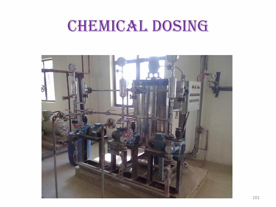
Chemical Dosing
101
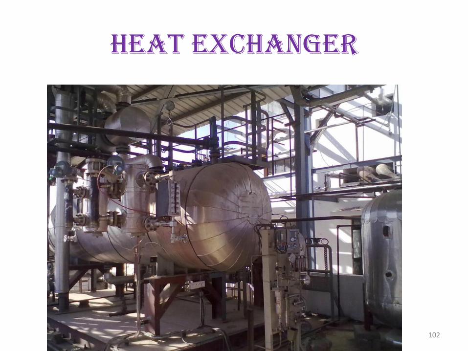
Heat Exchanger
102
Heat Exchanger
103
Steam turbine
104
Condenser
105
Steam Ejector
106
Steam Ejector Condenser
107
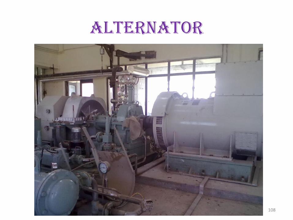
Alternator
108
Electrical Panels
109
HT and LT Panels
110
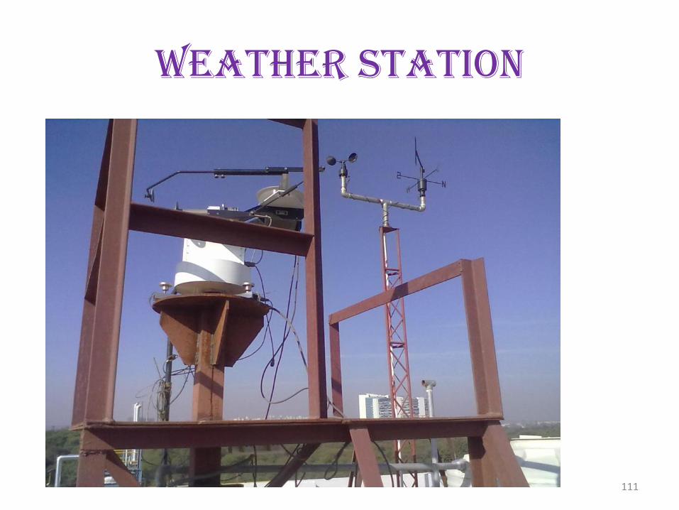
Weather Station
111
DIGNITARIES AT PROJECT SITE
112
Operational Problems
114
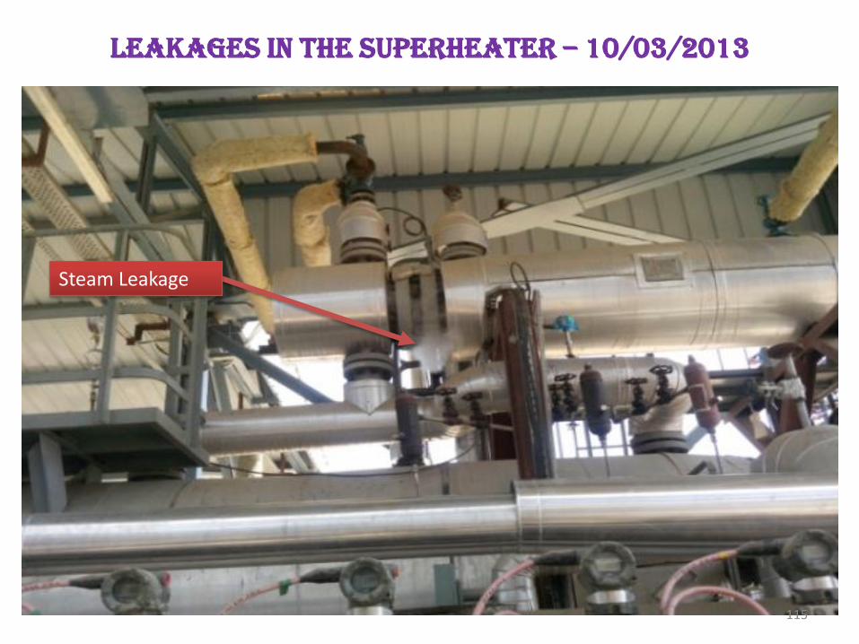
Leakages in the superheater – 10/03/2013
Steam Leakage
115
receiver glass window breakage the LFR system
Breakage of the receiver window glass
Receiver Window Glass Breakage
Interruption in power supply to the tracking motors, focus shifted partially
116
Equipment Problems
Dry run of the boiler feed pump
• Malfunction of Level transmitter on the Deaerator led to dry
running of boiler feedwater pump (BFP)
119
Communication problem between level I and level II
Control System Hierarchy for the solar thermal power plant
123
Steam System valves
• Problem in complete closing of the valve
• Manual closing of Valve – Not possible
• NRV leakages, allows return flow
• Leakages in control Valve in the Steam Line – problems in regulating the pressure
Control Valve with HandleControl Valve without Handle 124
System Problems
125
HTF Freezing
9
10
11
12
13
14
151
2:0
0 A
M
12
:30
AM
1:0
0 A
M
1:3
0 A
M
2:0
0 A
M
2:3
0 A
M
3:0
0 A
M
3:3
0 A
M
4:0
0 A
M
4:3
0 A
M
5:0
0 A
M
5:3
0 A
M
6:0
0 A
M
6:3
0 A
M
7:0
0 A
M
7:3
0 A
M
8:0
0 A
M
8:3
0 A
M
Am
bie
nt
Tem
per
atu
re (
oC
)
Time (hr: min)
Ambient temperature profile at the project site on February 24th, 2013
• Crystallization temperature of HTF Therminol VP1 is 12°C
126
Pump Seal Failure: February, 2013
129
Mirror Broken by Neel Gai
133
Mirror Breakage in LFR
134
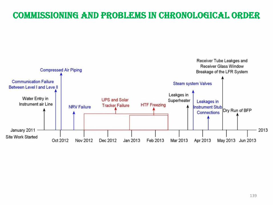
Commissioning and problems in chronological order
139
Site Issues• Low radiation
• IBR
• Cleaning the steam line for turbine
• Dirt and dust at site:
– Land treatment needed, done
– Problems in mirror cleaning
• Theft and Robbery: Security problems
• No grid power at site for 8 months
– Use of DG sets
140
Comments and status: Performance
• Performance of both solar fields being tested since April 2013
• Electrical power of 100 to 200 kW fed into local grid of SEC from Sept to Nov 2013
• Performance hampered by– Dust on mirrors and issues related to cleaning– Low and intermittent radiation– Imbalance of fluid flow in solar field loops– Non-perfect focusing– Daily starting without auxiliary firing– Non-availability of grid power– Issues with grid power connectivity
141
Solar Thermal Simulator
• Unique features:
o Simulation of user defined plant configurations
o Design point as well as off-design simulations
o Cost analysis
• Simulator predict:
o performance of each equipment of the plant
o annual power generation
o capital cost
o cost of energy
• How Simulator is useful
o preliminary sizing and cost estimation
o heat balance design
o parametric studies
o performance evaluation of a small subset of a complete plant or a complete plant
o optimize the plant configuration through multiple simulations
o devise the overall control strategy
• using different control options
o determine the start-up procedures
Solar Thermal Simulator
Features• Graphical user interface
• Freedom to construct flow sheets using any of the equipment
o Flexibility to simulate user defined small subset of a complete plant or a complete plant
• Equipment model library with database as well as manual entry of the parameters
• Model library for solar insolation and different climatic parameters
• Model library for different working fluids
• User defined time step and time horizon for the simulation
• Results in the form of tables and graphs
• Facility to export results to MS Excel file
User Interface: Main Window
Generation of user defined process flow diagram using user interface
References
Desai, N.B., Bandyopadhyay, S., ‘Solar Thermal Power Plant Simulator’, Proceedings of International Conference on Energy Security, Global Warming and Sustainable Climate -Solaris2012, Varanasi, India, 2012
Desai N.B., Bandyopadhyay S., Kedare S.B., Banerjee R., NayakJ.K., ‘Simulation of 1MWe Solar Thermal Power Plant’, The ISES Solar World Congress 2013, Cancun, Mexico, November 2013
Kartheek N.G.R., Yadav D., Banerjee R., Nayak J.K., BandyopadhyayS., Kedare S.B., ‘Experiences in commissioning of a 1 MW solar thermal power plant in Gurgaon’, 4th International conference on Advances in Energy Research – ICAER 2013, IIT Bombay, India, 10-12 December 2013