+ All Categories
Home > Documents > Design by Analysis versus Design by Formula of a PWR ... · PDF fileDesign by Analysis versus...

Design by Analysis versus Design by Formula of a PWR ... · PDF fileDesign by Analysis versus...

Date post: 30-Jan-2018
Category:
Upload: lexuyen
View: 220 times
Download: 2 times
Share this document with a friend
5
AbstractA pressure vessel can be designed using the rules of design by formulaand design by analysis. The objective of this research work is to compare the design of a reactor pressure vessel (RPV) using the two approaches. A typical RPV of a 300MW pressurized water reactor (PWR) was selected for the analysis. A nuclear grade steel ‘SA-508 Gr.3 Cl.1’ was used as a material of the RPV for the comparison. It has been concluded that the application of the design by analysisallows removing the unnecessary conservatism caused by applying the design by formulaapproach. This study recommends that the maximum allowable pressure of the RPV may be increased up to 17.70 % by using design by analysisapproach as described in ASME code. Index Termsdesign by analysis, PWR, RPV I. INTRODUCTION AKISTAN is currently passing the era in which huge energy crises has increased the importance of engineering research related to nuclear power plants. In the field of the nuclear power plants, pressurized water reactor (PWR) is one of the common reactor types. The world’s first PWR was installed, in the USA, in 1956 [1, 2]. PWR is a light-water moderated and light-water cooled nuclear thermal power reactor. The reactor pressure vessel (RPV) is the most vital component of a reactor as it contains the nuclear core and various control mechanisms under high pressure and high temperature. The pressurized light-water is used as a reactor’s coolant and it enters the RPV through the set-in nozzle (see Fig. 1). The set-in nozzles are normally used as the inlet nozzles in reactor pressure vessels [2, 3]. The set-in nozzles have flange set into the vessel wall. After receiving heat from the nuclear core, the reactor coolant leaves the vessel through the outlet nozzle of the RPV (see Fig. 1) [2, 4]. Reactor pressure vessels are complex geometries and essentially have openings, nozzles, and other attachments which produce geometric discontinuities. The effect of concentration of stresses due to geometric discontinuities is one of the basic considerations in the design of a pressure vessels [5] . The elementary stress equations no longer prevail in the vicinity of the geometric discontinuities. It is due to the fact that geometric discontinuities significantly Manuscript received Dec 05, 2014. The financial assistance of PIEAS, for this study, is highly acknowledged. U. T. Murtaza is a Ph.D. scholar in Pakistan Institute of Engineering and Applied Sciences (PIEAS), PO 45650 Pakistan (phone: 0092-51- 2207380/4x3414; fax: 0092-51-9248600; e-mail: [email protected]). M. J. Hyder is a professor in PIEAS, PO 45650 Pakistan (e-mail: [email protected]). alter the stress distributions in their surroundings. The geometric discontinuities are called "stress raisers" and the region in which they occur are called the areas of stress concentrations [6]. The design and manufacturing of the nuclear reactor pressure vessels are traditionally governed by the mandatory codes which certify high safety operation. The design by formulaapproach described in ASME code [7] undertake a membrane stress state condition for the determination of shell thickness of the RPV and assume large factors of safety in the areas of stress concentrations and geometric discontinuities. It should be noted that large safety factors essentially increase the thickness of the component, while safety is not necessarily increased. It is due to the fact that fracture toughness normally decreases with the increase of the thickness of the component [8, 9]. In addition to this, in corrosive environments, the stress corrosion cracking is expected to be higher in thicker parts [10]. The objective of this research work is to compare the design of the RPV, using two approaches called design by analysis(DBA) and design by formula(DBF) [7]. ANSYS Workbench has been used for DBA here which is a finite-element-based commercial software. After 2000, finite element analysis (FEA) was included as a standard practice in most of pressure vessels design codes. The approach described in ASME code, Section III, division 1 article NB-3200 [7] has been referred to as DBA, and will be followed for this research. The ASME III, division 1 presents rules for construction of nuclear facility class 1 components. The use of two dimensional and three dimensional shell element models is very common in the finite element stress analysis of pressure vessels [11-15]. These models are computationally efficient but contain certain inaccuracies especially in the areas of geometrical discontinuities. In the present study, a full 3D solid finite element model of the RPV, developed in our previous work [2], has been used for accurate computations of the stress state. II. PROBLEM DESCRIPTION Fig. 1 shows a typical double loop cylindrical RPV [2, 16] of a 300 MW pressurized water reactor. The engineering drawing of the RPV is shown in Fig. 1 (a). The RPV has been supported using the support pads under the nozzles as shown in Fig. 1 (b). The closer view of the set-in nozzle is given in Fig. 2 for showing the details of the nozzle. The set- in nozzle has conical taper of 6 degree at the nozzle-cylinder intersection as depicted in Fig. 2. It is a typical vertical RPV normally used in many PWR’s. Design by Analysis versus Design by Formula of a PWR Reactor Pressure Vessel Usman Tariq Murtaza, Mohammad Javed Hyder P Proceedings of the International MultiConference of Engineers and Computer Scientists 2015 Vol II, IMECS 2015, March 18 - 20, 2015, Hong Kong ISBN: 978-988-19253-9-8 ISSN: 2078-0958 (Print); ISSN: 2078-0966 (Online) IMECS 2015
Transcript

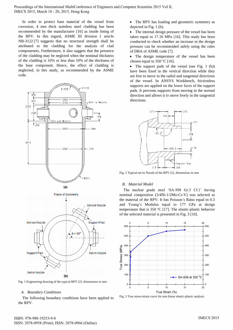
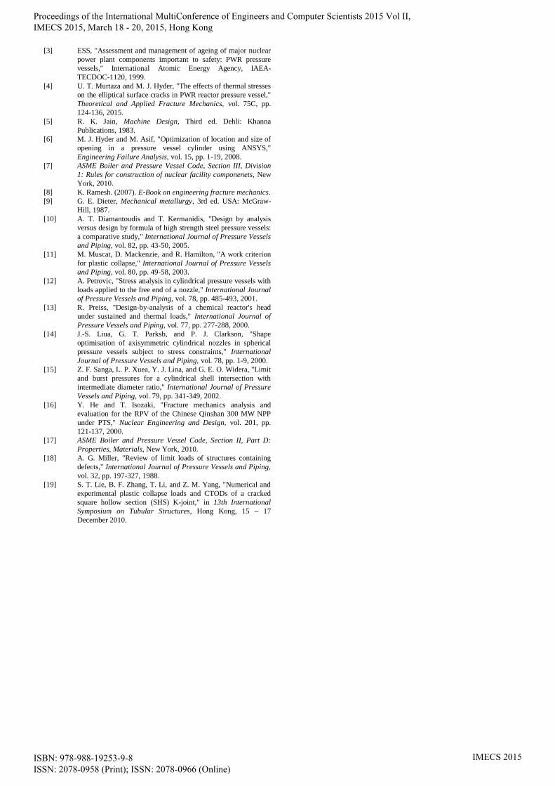
Abstract— A pressure vessel can be designed using the rules

of ‘design by formula’ and ‘design by analysis’. The objective

of this research work is to compare the design of a reactor

pressure vessel (RPV) using the two approaches. A typical RPV

of a 300MW pressurized water reactor (PWR) was selected for

the analysis. A nuclear grade steel ‘SA-508 Gr.3 Cl.1’ was used

as a material of the RPV for the comparison. It has been

concluded that the application of the ‘design by analysis’ allows

removing the unnecessary conservatism caused by applying the

‘design by formula’ approach. This study recommends that the

maximum allowable pressure of the RPV may be increased up

to 17.70 % by using ‘design by analysis’ approach as described

in ASME code.

Index Terms—design by analysis, PWR, RPV

I. INTRODUCTION

AKISTAN is currently passing the era in which huge

energy crises has increased the importance of

engineering research related to nuclear power plants. In the

field of the nuclear power plants, pressurized water reactor

(PWR) is one of the common reactor types. The world’s first

PWR was installed, in the USA, in 1956 [1, 2]. PWR is a

light-water moderated and light-water cooled nuclear

thermal power reactor. The reactor pressure vessel (RPV) is

the most vital component of a reactor as it contains the

nuclear core and various control mechanisms under high

pressure and high temperature. The pressurized light-water

is used as a reactor’s coolant and it enters the RPV through

the set-in nozzle (see Fig. 1). The set-in nozzles are normally

used as the inlet nozzles in reactor pressure vessels [2, 3].

The set-in nozzles have flange set into the vessel wall. After

receiving heat from the nuclear core, the reactor coolant

leaves the vessel through the outlet nozzle of the RPV (see

Fig. 1) [2, 4].

Reactor pressure vessels are complex geometries and

essentially have openings, nozzles, and other attachments

which produce geometric discontinuities. The effect of

concentration of stresses due to geometric discontinuities is

one of the basic considerations in the design of a pressure

vessels [5] . The elementary stress equations no longer

prevail in the vicinity of the geometric discontinuities. It is

due to the fact that geometric discontinuities significantly

Manuscript received Dec 05, 2014. The financial assistance of PIEAS,

for this study, is highly acknowledged.

U. T. Murtaza is a Ph.D. scholar in Pakistan Institute of Engineering

and Applied Sciences (PIEAS), PO 45650 Pakistan (phone: 0092-51-

2207380/4x3414; fax: 0092-51-9248600; e-mail: [email protected]).

M. J. Hyder is a professor in PIEAS, PO 45650 Pakistan (e-mail:

[email protected]).

alter the stress distributions in their surroundings. The

geometric discontinuities are called "stress raisers" and the

region in which they occur are called the areas of stress

concentrations [6]. The design and manufacturing of the

nuclear reactor pressure vessels are traditionally governed

by the mandatory codes which certify high safety operation.

The ‘design by formula’ approach described in ASME code

[7] undertake a membrane stress state condition for the

determination of shell thickness of the RPV and assume

large factors of safety in the areas of stress concentrations

and geometric discontinuities. It should be noted that large

safety factors essentially increase the thickness of the

component, while safety is not necessarily increased. It is

due to the fact that fracture toughness normally decreases

with the increase of the thickness of the component [8, 9]. In

addition to this, in corrosive environments, the stress

corrosion cracking is expected to be higher in thicker parts

[10].

The objective of this research work is to compare the

design of the RPV, using two approaches called ‘design by

analysis’ (DBA) and ‘design by formula’ (DBF) [7].

ANSYS Workbench has been used for DBA here which is a

finite-element-based commercial software. After 2000, finite

element analysis (FEA) was included as a standard practice

in most of pressure vessels design codes. The approach

described in ASME code, Section III, division 1 article

NB-3200 [7] has been referred to as DBA, and will be

followed for this research. The ASME III, division 1

presents rules for construction of nuclear facility class 1

components.

The use of two dimensional and three dimensional shell

element models is very common in the finite element stress

analysis of pressure vessels [11-15]. These models are

computationally efficient but contain certain inaccuracies

especially in the areas of geometrical discontinuities. In the

present study, a full 3D solid finite element model of the

RPV, developed in our previous work [2], has been used for

accurate computations of the stress state.

II. PROBLEM DESCRIPTION

Fig. 1 shows a typical double loop cylindrical RPV [2, 16]

of a 300 MW pressurized water reactor. The engineering

drawing of the RPV is shown in Fig. 1 (a). The RPV has

been supported using the support pads under the nozzles as

shown in Fig. 1 (b). The closer view of the set-in nozzle is

given in Fig. 2 for showing the details of the nozzle. The set-

in nozzle has conical taper of 6 degree at the nozzle-cylinder

intersection as depicted in Fig. 2. It is a typical vertical RPV

normally used in many PWR’s.

Design by Analysis versus Design by Formula

of a PWR Reactor Pressure Vessel

Usman Tariq Murtaza, Mohammad Javed Hyder

P

Proceedings of the International MultiConference of Engineers and Computer Scientists 2015 Vol II, IMECS 2015, March 18 - 20, 2015, Hong Kong

ISBN: 978-988-19253-9-8 ISSN: 2078-0958 (Print); ISSN: 2078-0966 (Online)

IMECS 2015

In order to protect base material of the vessel from

corrosion, 4 mm thick stainless steel cladding has been

recommended by the manufacturer [16] as inside lining of

the RPV. In this regard, ASME III division 1 article

NB-3122 [7] suggests that no structural strength shall be

attributed to the cladding for the analysis of clad

componenets. Furthermore, it also suggets that the presence

of the cladding may be neglcted when the nominal thickness

of the cladding is 10% or less than 10% of the thickness of

the base component. Hence, the effect of cladding is

neglected, in this study, as recommended by the ASME

code.

Fig. 1 Engineering drawing of the typical RPV [2], dimensions in mm

A. Boundary Conditions

The following boundary conditions have been applied to

the RPV.

The RPV has loading and geometric symmetry as

depicted in Fig. 1 (b).

The internal design pressure of the vessel has been

taken equal to 17.16 MPa [16]. This study has been

conducted to check whether an increase in the design

pressure can be recommended safely using the rules

of DBA of ASME code [7].

The design temperature of the vessel has been

chosen equal to 350 oC [16].

The support pads of the vessel (see Fig. 1 (b))

have been fixed in the vertical direction while they

are free to move in the radial and tangential directions

of the vessel. In ANSYS Workbench, frictionless

supports are applied on the lower faces of the support

pads. It prevents supports from moving in the normal

direction and allows it to move freely in the tangential

directions.

Fig. 2 Typical set-in Nozzle of the RPV [2], dimensions in mm

B. Material Model

The nuclear grade steel ‘SA-508 Gr.3 Cl.1’ having

nominal composition (3/4Ni-1/2Mo-Cr-V) was selected as

the material of the RPV. It has Poisson’s Ratio equal to 0.3

and Young’s Modulus equal to 177 GPa at design

temperature that is 350 oC [17]. The elastic-plastic behavior

of the selected material is presented in Fig. 3 [16].

Fig. 3 True stress-strain curve for non-linear elastic-plastic analysis

Proceedings of the International MultiConference of Engineers and Computer Scientists 2015 Vol II, IMECS 2015, March 18 - 20, 2015, Hong Kong

ISBN: 978-988-19253-9-8 ISSN: 2078-0958 (Print); ISSN: 2078-0966 (Online)

IMECS 2015

III. DBA APPROACH

The DBA of nuclear facility class 1 components has been

performed following the two application rules described in

ASME Section III, division 1 [7].

In application rule 1, the elastic-plastic analysis including

strain hardening and large deformation effects is needed to

be performed for determining the plastic analysis collapse

load. In DBA the plastic analysis collapse load is taken as

the load producing gross plastic deformation (GPD) and

used to specify the allowable load. ASME III, division 1

article NB-3228 requires that “…the specified loading do

not exceed two-thirds of the plastic analysis collapse

load…”. Thus the allowable load is

2

3a pP P (1)

where ‘Pp’ is the plastic analysis collapse load. The plastic

analysis collapse load can be determined using the twice-

elastic-slope (TES) criterion specified in ASME Section III,

division 1 mandatory appendix II-1430. The TES criterion is

based on the load-deformation response of the vessel as

obtained by elastic-plastic analysis [11]. A structural

response curve is plotted with load as ordinate and

deformation as the abscissa. The angle that the linear part of

the load-deflection curve makes with the ordinate is called

‘θ’. A second straight line, called hereinafter ‘the collapse

limit line’, is drawn through the origin so that it makes an

angle 1tan (2 tan ) with the ordinate. The plastic

analysis collapse load (Pp) is the load corresponding to the

intersection of the load-deformation curve and the collapse

limit line [18, 19].

In application rule 2, ASME III, division 1 article NB-

3228.5 requires that the range of primary plus secondary

membrane plus bending stress intensity should be 3 .mS

max min( ) 3 mS (2)

where, ‘Sm’ is the design stress intensity value tabulated in

ASME II, part D, subpart 1, Tables 2A [17]. ‘σmax’ and ‘σmin’

are the largest and smallest principal stresses,

correspondingly. The left hand side of the Eq. (2) is the

value of the stress intensity according to Tresca yield

criterion [9].

IV. FINITE ELEMENT MODEL OF THE RPV

In our previous research work [2], a full hexahedral model

of the RPV was developed in order to optimize the

dimensions of the set-in nozzle. The same FE model has

been used for DBA in this study. The full three dimensional

finite element model of the RPV is shown in Fig. 4. The FE

model contains a total of 89642 hexahedral or brick

elements. The type of the element used is Solid-186. This is

a 20 nodes, higher order 3-D brick element.

A preliminary elastic-plastic finite element analysis of the

RPV, using the material model as presented in Fig. 3 and the

developed FE model as shown in Fig. 4, was performed at

the internal pressure of 17.16 MPa. The hoop stress

distributions in the RPV are presented in Fig. 5. It is evident

from the figure that the set-in nozzle-cylinder junction is the

highest stress concentration point (HSCP) of the RPV. The

value of hoop stress at the HSCP is around 291.6 MPa.

Fig. 4 Full 3D solid-186 finite elements model [2]

Fig. 5 Hoop stress distributions, stresses in MPa

Proceedings of the International MultiConference of Engineers and Computer Scientists 2015 Vol II, IMECS 2015, March 18 - 20, 2015, Hong Kong

ISBN: 978-988-19253-9-8 ISSN: 2078-0958 (Print); ISSN: 2078-0966 (Online)

IMECS 2015

V. DBA VERSUS DBF LIMIT LOAD ANALYSIS

The maximum limit load capability of the RPV was

investigated using the DBA and DBF procedures in this

Section.

For DBA, elastic-platic finite element analysis of the RPV

was conducted applying the incremental iterative approach

using the ANSYS Workbench. The internal pressure was

increased in steps from the design pressure of 1MPa. The

displacement of the RPV in the radial direction was noted

for each incremental step and has been presented in Fig. 6.

The collapse load (described in Section III) obtained from

the plastic analysis is 33 MPa.

According to application rule 1, as described in Section

III and Eq. (1), the maximum allowable pressure for the

RPV is (2 / 3) 33 22aP MPa .

According to application rule 2, as described in Section

III, the max. stress intensity should be less than 3Sm. The

design stress intensity, Sm for ‘SA-508 Gr.3 Cl.1’ material is

184 MPa [17]. Hence, max. stress intensity should be less

than 552 MPa.

33

Collapse limit line according to ASME

θ

ϕ

Fig. 6 Radial displacement of the RPV

Using the max. allowable pressure Pa = 22 MPa, the

distributions of stress intensity in the RPV are shown in Fig.

7. The max. stress intensity is equal to 441.2 MPa which is

around the set-in nozzle of the RPV. Hence, the limiting

condition of the rule 2 as described above is also satisfied

under the application of max. allowable pressure.

The max. allowable pressure according to rules of DBF

was calculated using the relationship given in article NB-

3320 of ASME III, division 1. The cylindrical portion of the

RPV is called the beltline region of the RPV. The allowable

pressure calculated on the basis of the beltline region of the

RPV is definitely the max. allowable pressure as because

RPV cannot withsatand pressure more than this pressure in

any case. The formula [7] for cylindrical vessel is given in

Eq. (3):

max

0.5

mt SP

R t

(3)

where:

t = Thickness of the shell

Sm = Design stress intensity values

R = Inner radius of the shell

The maximum allowable pressure according to DBA and

DBF calculations along with percentage differences between

them are given in Table I.

Fig. 7 Distributions of stress intensity (MPa) in the RPV

TABLE I

MAXIMUM ALLOWABLE PRESSURE USING DBA AND DBF

DBF (MPa) DBA (MPa) % Difference

RPV 18.105 22 17.70

VI. CONCLUSION

In this paper we have compared the design of the RPV

made of ‘SA-508 Gr.3 Cl.1’ material using ‘design by

analysis’ and ‘design by formula’ rules. We can conclude

from the comparative study as follows:

The application of the ‘design by analysis’ allows

removing the unnecessary conservatism caused by

applying the ‘design by formula’ approach.

An increase of 17.70 % in the maximum allowable

pressure is recommended when RPV is designed

using the rules of ‘design by analysis’ instead of

‘design by formula’.

REFERENCES

[1] Y. Bangash, "PWR steel pressure vessel design and practice,"

Progress in Nuclear Energy, vol. 16(1), pp. 1-40, 1985.

[2] U. T. Murtaza and M. J. Hyder, "Optimization of the Size and

Shape of the Set-in Nozzle for a PWR Reactor Pressure Vessel,"

Nuclear Engineering and Design,

10.1016/j.nucengdes.2014.12.040., 2015.

Proceedings of the International MultiConference of Engineers and Computer Scientists 2015 Vol II, IMECS 2015, March 18 - 20, 2015, Hong Kong

ISBN: 978-988-19253-9-8 ISSN: 2078-0958 (Print); ISSN: 2078-0966 (Online)

IMECS 2015

[3] ESS, "Assessment and management of ageing of major nuclear

power plant components important to safety: PWR pressure

vessels," International Atomic Energy Agency, IAEA-

TECDOC-1120, 1999.

[4] U. T. Murtaza and M. J. Hyder, "The effects of thermal stresses

on the elliptical surface cracks in PWR reactor pressure vessel,"

Theoretical and Applied Fracture Mechanics, vol. 75C, pp.

124-136, 2015.

[5] R. K. Jain, Machine Design, Third ed. Dehli: Khanna

Publications, 1983.

[6] M. J. Hyder and M. Asif, "Optimization of location and size of

opening in a pressure vessel cylinder using ANSYS,"

Engineering Failure Analysis, vol. 15, pp. 1-19, 2008.

[7] ASME Boiler and Pressure Vessel Code, Section III, Division

1: Rules for construction of nuclear facility componenets, New

York, 2010.

[8] K. Ramesh. (2007). E-Book on engineering fracture mechanics.

[9] G. E. Dieter, Mechanical metallurgy, 3rd ed. USA: McGraw-

Hill, 1987.

[10] A. T. Diamantoudis and T. Kermanidis, "Design by analysis

versus design by formula of high strength steel pressure vessels:

a comparative study," International Journal of Pressure Vessels

and Piping, vol. 82, pp. 43-50, 2005.

[11] M. Muscat, D. Mackenzie, and R. Hamilton, "A work criterion

for plastic collapse," International Journal of Pressure Vessels

and Piping, vol. 80, pp. 49-58, 2003.

[12] A. Petrovic, "Stress analysis in cylindrical pressure vessels with

loads applied to the free end of a nozzle," International Journal

of Pressure Vessels and Piping, vol. 78, pp. 485-493, 2001.

[13] R. Preiss, "Design-by-analysis of a chemical reactor's head

under sustained and thermal loads," International Journal of

Pressure Vessels and Piping, vol. 77, pp. 277-288, 2000.

[14] J.-S. Liua, G. T. Parksb, and P. J. Clarkson, "Shape

optimisation of axisymmetric cylindrical nozzles in spherical

pressure vessels subject to stress constraints," International

Journal of Pressure Vessels and Piping, vol. 78, pp. 1-9, 2000.

[15] Z. F. Sanga, L. P. Xuea, Y. J. Lina, and G. E. O. Widera, "Limit

and burst pressures for a cylindrical shell intersection with

intermediate diameter ratio," International Journal of Pressure

Vessels and Piping, vol. 79, pp. 341-349, 2002.

[16] Y. He and T. Isozaki, "Fracture mechanics analysis and

evaluation for the RPV of the Chinese Qinshan 300 MW NPP

under PTS," Nuclear Engineering and Design, vol. 201, pp.

121-137, 2000.

[17] ASME Boiler and Pressure Vessel Code, Section II, Part D:

Properties, Materials, New York, 2010.

[18] A. G. Miller, "Review of limit loads of structures containing

defects," International Journal of Pressure Vessels and Piping,

vol. 32, pp. 197-327, 1988.

[19] S. T. Lie, B. F. Zhang, T. Li, and Z. M. Yang, "Numerical and

experimental plastic collapse loads and CTODs of a cracked

square hollow section (SHS) K-joint," in 13th International

Symposium on Tubular Structures, Hong Kong, 15 – 17

December 2010.

Proceedings of the International MultiConference of Engineers and Computer Scientists 2015 Vol II, IMECS 2015, March 18 - 20, 2015, Hong Kong

ISBN: 978-988-19253-9-8 ISSN: 2078-0958 (Print); ISSN: 2078-0966 (Online)

IMECS 2015


Recommended