COMPONENT PART NOTICE THIS PAPER IS A CO PONENT PART OF THE FOLLOWING COMPILATION REPORT: TIM.E: Engine Rammnan tn Dl4*tnreind lnfln- COend(f(nnm, inga'* PneAnd4nga. of the Propulsion and Enargetic.. Specialists' Meeting (68th) Held In Munich, Gemany on 8-9 September 1986. To ORDER THE COMPLETE COMPILATION REPORT, USE AD-A182 635 THE COMPONENT PART IS PROVIDED HERE TO ALLOW USERS ACCESS TO INDIVIDUALLY AUTHORED SECTIONS OF PROCEEDING, ANNALS, SYMPOSIA, ETC. HOWEVER, THE COMP'ONENT SHOULD BE CONSIDERED WITHIN THE CONTEXT OF THE OVERALL COMPILATION REPORT AND NOT AS A STAND-ALONE TECHNICAL REPORT. THE FOLLOWING COMPONENT PART NUMBERS COMPRISE THE COMPILATION REPORT: AD#: P005 462 thru P005 473 A__ _ AD#: AD#:- AN: AM:_ AteosAiOn Fow NIrIS ORA61 DTIO TAB Una ounesd E Just itioatio Distribution/ Avalabilit? 00403 =" DTIC_ Dims, ilpeola3 ELD I i ,...- -,A i TinLmm -m ' i DT~c 1 R~L~ad a%_________a__ OPI: !'fIC-TID
Transcript
COMPONENT PART NOTICE
THIS PAPER IS A CO PONENT PART OF THE FOLLOWING COMPILATION REPORT:
of the Propulsion and Enargetic.. Specialists' Meeting (68th) Held
In Munich, Gemany on 8-9 September 1986.
To ORDER THE COMPLETE COMPILATION REPORT, USE AD-A182 635
THE COMPONENT PART IS PROVIDED HERE TO ALLOW USERS ACCESS TO INDIVIDUALLYAUTHORED SECTIONS OF PROCEEDING, ANNALS, SYMPOSIA, ETC. HOWEVER, THE COMP'ONENTSHOULD BE CONSIDERED WITHIN THE CONTEXT OF THE OVERALL COMPILATION REPORT AND
NOT AS A STAND-ALONE TECHNICAL REPORT.
THE FOLLOWING COMPONENT PART NUMBERS COMPRISE THE COMPILATION REPORT:
*** P rof.Dr.-Ing., Universitlt der Bundeswehr MtinchesD-8014 Neubiberg, Germany
W orner-lisenborg-Nog 39
ABSTRACT '
eA in objective of this investigation is to assess the influence of differenttypes and magnitudes of swirl on the performance and compatibility of turbdfoet engines.The generation of intake swirl, typical for many supersonic combat aircraft-is described.Essentially two basic types, i.e. twin swirl and bulk swirl of varying strength and alsocombinations thereof, have been selected in order to simulate these swirl patterns bysubsoale swirl generators in a model wind tunnel. The swirl patterns measured behindthese generators show good agreement with the target patterns selected at the beginning.The small scale swirl generators are being rebuilt at full scale for subsequent testingin front of a Larzac enginn under static conditions with a bellmouth inl t at the enginetest facility of the Jet Propulsion Institute at the Universilt der Bunlenwehr %nchen.
LIST OF SYMBOLS LIST OF INVICS'
D duct diameter (mm) B bulk swirl
air fow (kg/s) HPC high pressure compressor
n rotor speed (rpm) LPC low pressure compressor
a angle of incidence (degree) max maximum6a angle of subsonic intake ramp (degree) T twin swirle angle of circumferential position (degree)
T angle of swirl (degree)
ff total pressure ratio (../..)
€ leading edge sweep angle (degree)
LIST OF CONTENTS
I. Introduction
2. ources and types of intake swirl distortion2.1 Twin swirl2.2 Sulk swirl2.3 Combination of bulk and twin swirl2.4 TORNADO intake swirl
3. Simulation of intake swirl
4. Model investigations4.1 Model simulation of intake swirl4.2 Results of the model wind tunnel tests
5. lull scale investigations
4. Conclusions
7. References
8.' Figures
18-2
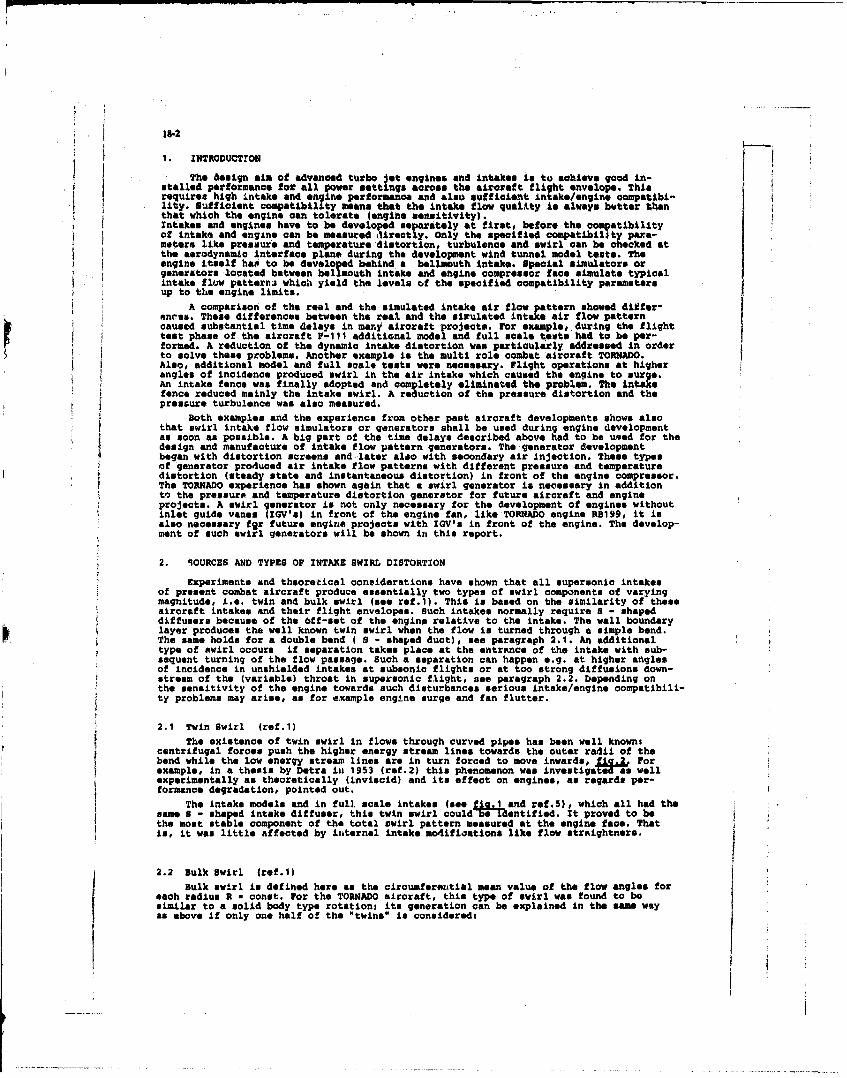
1. INTRODUCTION
The design aim of advanced turbo lot engines and intakes is to achieve good in-stalled performance for all power settings across the aireraft flight envelope. Thisrequires high intake and engine performance and also sufficient intake/engine compatibi-lity. Sufficient compatibility mean. that the intake flow quality is always better thanthat which the engine can tolerate (engine sensitivity).Intakes and engines have to be developed separately at first, before the compatibilityof intake and engine can be measured directly. only the specified compatibility para-meters like pressure and temperature distortion, turbulence and swirl can be checked atthe aerodynamic interface plane during the development wind tunnel model tests. Theengine itself has to be developed behind a bellmouth intake. Special simulators orgenerators located between bellmouth intake and engine compressor face simulate typicalintake flow patterni which yield the levels of the specified compatibility parametersup to the engine limits.
A comparison of the real and the simulated intake air flow pattern showed differ-onriu. These differences between the real and the sirulated intake air flow patterncaused substantial time delays in many aircraft projects. For example, during the flighttest phase of the aircraft r-111 additional model and full scale tests had to be per-formed. A reduction of the dynamic intake distortion was particularly addressed in orderto solve these problems. Another example is the multi role combat aircraft TORNADO.Also, additional model and full scale tests were necessary. Flight operations at higherangles of incidence produced swirl in the air intake which caused the engine to surge.An intake fence was finally adopted and completely eliminated the problem. The intakefence reduced mainly the intake swirl. A reduction of the pressure distortion and thepressure turbulence was also measured.
Both examples and the experience from other past aircraft developments shows alsothat swirl intake flow simulators or generators shall be used during engine developmentas soon as possible. A big part of the time delays described above had to be used for thedesign and manufacture of intake flow pattern generators. The generator developmentbegan with distortion screens and later also with secondary air Injection. These typesof generator produced air intake flow patterns with different pressure and temperaturedistortion (steady state and instantaneous distortion) in front of the engine compressor.The TORNADO experience has shown again that a swirl generator is necessary in additionto the pressure and temperature distortion generator for future aircraft and engineprojects. A swirl generator is not only necessary for the development of engines withoutinlet guide vanes (IGV's) in front of the engine fan, like TORNADO engine RB199, it isalso necessary fgr future engine projects with IGV's in front of the engine. The develop-ment of' such swirl generators will be shown in this report.
2. SOURCES AND TYPES OF INTAKE SWIRL DISTORTION
Experiments and theoretical considerations have shown that all supersonic intakesof present combat aircraft produce essentially two types of swirl components of varyingmagnitude, i.e. twin and bulk swirl (see ref.1). This is based on the similarity of theseaircraft intakes and their flight envelopes. Such intakes normally require S - shapeddiffusers because of the off-set of the engine relative to the intake. The wall boundarylayer produces the well known twin swirl when the flow is turned through a simple bend.The same holds for a double bend ( S - shaped duct), see paragraph 2.1. An additionaltype of swirl occurs if separation takes place at the entrance of the intake with sub-sequent turning of the flow passage. Such a separation can happen e.g. at higher anglesof incidence in unshielded intakes at subsonic flights or at too strong diffusions down-stream of the (variable) throat in supersonic flight, see paragraph 2.2. Depending onthe sensitivity of the engine towards such disturbances serious intake/engine compatibili-ty problems may arise, as for example engine surge and fan flutter.
2.1 Twin Swirl (ref.1)
The existence of twin swirl in flows through curved pipes has been well known:centrifugal forces push the higher energy stream lines towards the outer radii of thebend while the low energy stream lines are in turn forced to move inwards, f Forexample, in a thesis by Detra in 1953 (ref.2) this phenomenon was investigaa wellexperimentally as theoretically (inviscid) and its effect on engines, as regards per-formance degradation, pointed out.
The intake models and in full scale intakes (see .1 and ref.5), which all had thesame 8 - shaped intake diffuser, this twin swirl could beIdentified. It proved to bethe most stable component of the total swirl pattern measured at the engine face. Thatis, it was little affected by internal intake modifications like flow straightners.
2.2 Bulk Swirl (ref.1)
Bulk swirl is defined here as the circumferential mean value of the flow angles foreach radius R - const. For the TORNADO aircraft, this type of swirl was found to besimilar to a solid body type rotations its generation can be explained in the same wayas above if only one half of the "twins is considered,
18-3
A region of low kinetic energy (low total pressure) located aosetrically at oneportion of the intake duct perimeter, e.g. either at the intake cowl or at the ramp(fit. 1), is pushed towards the inner radius of the bend while the high energy air ismoved outwards by centrifugal forces, as shown in 1c.3.
Fig.3 also explains why the bulk swirl $o contrarotational to the fan at subsonicspeed and high angles of incidence In the left nand engine and at supersonic speed andlow angles of incidence in the right hand engine respectively.
In contrast to the twin swirl, bulk swirl is rather sensitive, i.e. it changesconsiderable in magnitude and also in sign for varying external flow conditions Ifig.3)which define the position and sie of the region of low kinetic energy flow.
2.3 CoAbination of Twin and Bulk Swirl
Typical supersonic intake flow patterns as shown in hog.5 6. 7 andacombination of twin and bulk swirl. Pia.4 illustrates the superimpoi f these twobasic intake swirl oQmponents.
2.4 TORNADO Intake Swirl (ref.1)
At subsonio speeds both the twin and the bulk swirl increase (fig.5)i The extremesin deviation from the mean value, the local maximum and minimum values at the outermostmeasuring station R w 0,7-. R(max), are a measure of the strength of the twin swirl,which is more than doubled towards the high incidence end. The swirl being contra-rotational to the fan rotation of the left hand engine and obviously co-rotational tothe right hand engine.
At subsonic speed, Mach - 0,7, fig.7 shows the influence of the engine mass flow.Reducing the engine mass flow at intermediate incidences produced swirl angles ofsimilar magnitude, however, of opposite sign, fiq.7 (shaded area).
At supersonic speeds an analogous dependence of swirl versus second ramp angle (62)of the intake shock system was found, fig.6. The swirl being now largely contra-rota-tional to the fan rotation of the right hand engine and obviously co-rotational to theleft hand engine.
A comparison between model and full scale data was made under static conditions.As shown in fig.8, the flow angles at the duct wall of TORNADO prototype obtained bythe oil flow technique agree quite well with the flow angles measured in a TORNADO windtunnel model by a rotatable S arm rake having 24 five-hole probes. Thie agreement wasalso found in paragraph 4.1 and 4.2 (Moveable Swirl Generator). More details about theTORNADO model and full scale tests are described in ref.1.
3. SIMULATION OF INTA(E SWIRL
In the past only steady state and instantaneous (dynamic) pressure distortion wereparticularly attended during air intake and engine compatibility investigations. In 1977tests with a twin swirl generator in front of a compressor were published by the DFVLR(ref.3). After that Rolls Royce performed R8199 engine ril tests with fixed bulk swirlgenerators (ref.4). Swirl angles of T (bulk, max) - +,- 5 and +,- 100 were simulated.These swirl generators (DrVLR and Rolls Royce) simulated either twin or bulk swirl.
The simulation of typical supersonic aircraft intake flow patterns, as shown infig.5, 6, 7 and 8 for example, is the objective of the present work. These flow patternswith some simplifications will be simulated by fixed and moveable swirl generators.
Fixed swirl generators simulate selected specific intake flow patterns at the statictest rig. The advantages of a fixed swirl generator are their greater simplicity ascompared with moveable ones and also the simulation of the swirl distribution withnearly no total pressure disturbances. The effects on the engine of the pressure andswirl distortion can be measured separately.
Moveable swirl generators simulate as well selected specific intake swirl patternsas time variant intake swirl patterns which correspond to the flow patterns measuredfor all ground and flight conditions. The main advantage of a moveable swirl generator,as described below, is the fact that the magnitude of the swirl can be continuouslyvaried by the remote controlled variation of the wing incidence. This is important inan emergency situation, as for example, during a severe engine surge which requiresimmediate removal of the swirl disturbance.
4. MODEL INVZSTGATIONS
4.1 Model Simulation of Intake Swirl DistortionModel Wind Tunnel and Testing Technique
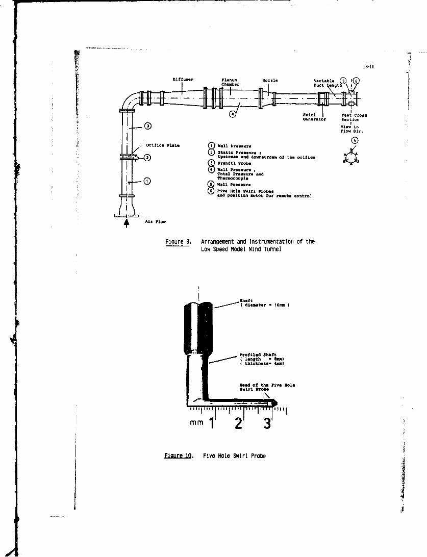
The model investigations were made in a low speed wind tunnel, installed in theengine test facility of the Jet Propulsion Institute at the UniversitAt der sundeswehrHdnohen. 11g. is a detailed sketch of its arrangement which consists of an orificeplate, a 9U- bond, a 34 diffuser# a plenum chamber, a nossle reducing the circularcross section to an internal diameter of 200 -m, the model swirl generator and themeasuring section. In frort of and in the plenum chamber screens and honeyombs aremounted in order to obtain uniform flow conditions over the whole cross section.
181
The air is supplied by a screw compressor with a pressure ratio of 2#8 and a constant
nas flow rate of 3,7 kg/s. Part of this mass flow rate can be blown off through aregulating valve, so that the mass flow rate through the wind tunnel easily can be
pad changed,.i
The device for measuring the flow patterns behind the model swirl generator con-sists of three 5-hole-probee with pyramdal probe hade (see * 0). These probes areequally positioned in the aircumferentlal direction of the measuring plane and can betraversed In radial direction. In addition wall static pressure holes are locatedmidwise between the S-hole-probes.
The fastening of the model swirl generator between nozzle and maanuring sectionis constructed in such a way that it can easily be turned around the oenter-axia.In this way the whole flow field behind the swirl generator can be measured with thethree 3-hole-probes. The distance between swirl generator and measuring plane can bevaried by different lengths of pipes.In addition to these measurements tests were made by using the oil flow technique forgetting informations about the flow conditions near the wall. This technique is basedon the assmption that small droplets of high viscosity are moving slowly in the direr-tion of the pssaing air flow. Thus a lot of small droplets of a suspension of oil anddye were applied at the duct wall in the plane to be measured. Then the model windtunnel was net in operation and kept at the desired mass flow rate for about fiveminutes. After shutting-down the air supply a copy of the trails of the dropleto wasobtained by pressing a shot of paper on the cylind,:ical duct wall. In this way It waspossible to obtain the wall flow pictures at different distances behind the swirlgenerator.
Model Swirl Distortion Generators
The aim of this investigation was not primarily to simulate exactly the flow condi-tions measured in the Tornado intake (refer, Chapt.2), but to carry out basic investi-gations by generating two basic swirl types and also combinations thereof of differentmagnitudes. Therefore the following model swirl generators were designedt
FIXED SWIRL GENERATORsWith this type of swirl generator the flow deflection is generated by guide vanes
which are individually cambered with respect to the desired flow deflection.For this purpose the flow fields of the two basic swirl types are described in simpletheoretical swirl modelss According to its definition bulk swirl is similar to a solidtype rotation. Thus the corresponding guide vane have to generate a flow deflectionwhich is linearly increasing in radial direction to a maximum value I B,MAX (see f .The twin swirl is a counter rotating double swirl which is approximated by a swirlmodel as shown in fi a. The model for determination of the local flow deflectionuses concentrical semicircles and straight lines which define the direction of the crossflow. The flow deflection along the x-axis corresponds to a cosine-distribution with themaximum at T T,MAX. The flow deflection along the semicircles and the straight partsfollows also a cosine-distribution with the correspondLnq maximum at the point ofintersection with the x-axis. In this way the flow defletion is defined in each pointof the cross section. As examples for the resulting theoretical flow deflections, thedistributions along the 45, 135, 225 and 3151-directions are shown in fig.12b.
Combinations of the two basic swirl typos result from the superposition of these
both swirl models specifying the values of T B,MAX and T T,MAX.Fixed model swirl senerators were designed to simulate the following swirl configurations,assuming zere deviation of the guide vanes as a rough approximations
Twin swirl Bulk swirl
200 06150 50104 10059 1500. 20*
Depending on the strength of the maximum deflection caused by bulk swirl and twin swirl,the combinations thereof have a different number of swirl centers. There exists onlyone swirl center if Y S,MAX ) r T,NAX, two centers if T B,KAX 4 r T,NAX and finallythree centers if T BJAX - T T,KAX (i.e. the maximum flow deflections of bulk swirl andtwin swirl are equal).
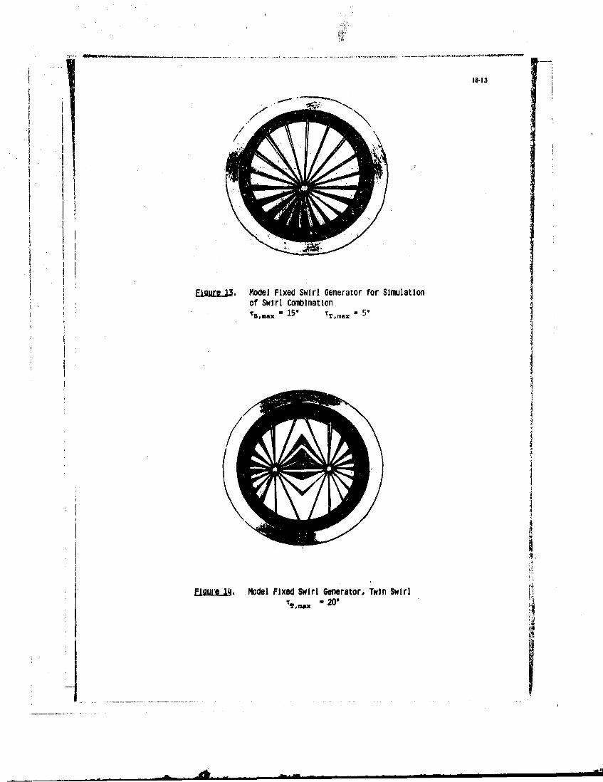
As an example fixed model swirl generators for the swirl configurtions " SAX * 150,i T,MAX -5* an4 - BMAX - 0, T T,MAX - 20* (i.e. pure twin swirl) are shotm in fF3.13and f&F.14.
NOVEABLE SWIRL GENERATORA slander sharp-edged delta wing generates two symmetrical vortex sheets above its
upper surface at specific angles of attack f7,7 (see _* g_). The vorticities aregenerated by flow separation at the sharp leadng-edges ofthe wing.
Therefore a sharp-edged delta wing with trapezoidal cross section was used as amoveable swirl generator. Its geometry is shown in fq.1. The main data are the leading-edge swoop angle of 60° (i.e. an aspect ratio of 2,7iE maximum thickness ratio of0,03 and the vertex angle of the bevelled leading-edges of about S0.
The adjustment of the angle of attack is cai ried out by two moveable sticks. Foraerodynamical purposes these sticks are covered by suitable shaped fairings (see ftq.17).
18-4
This mechanism allows to change the anqle of attack from O to 240 in steps of 3".
4.2 Results of the Model Wind Tunnel Tests
As was explained before the main objective of the model investigations was to gener-ate defined swirl patt4,xns with the present subscale swirl generators and to investigatethe influence of the distance between swirl generator and measureing plane on the stabilityof the generated Ciow field.
FIXED SWIRL URN3RATORSFor the fixed swirl generators the following progr.. of measurements using 5-hole-
probes was conductedt
fixed swirl generators for the distance between swirlfollowing swirl combinations generator and measuring plane
:s: D 2,5 D 4s D
B,MhX # TAX X XTR,my. 150, TTR5U X 5 X X
S'NlAX uSOt TtM A 10 X X
P,NAX 50, TT,A X is* X X
TB,M • 00, TT,MAX 20* X X X
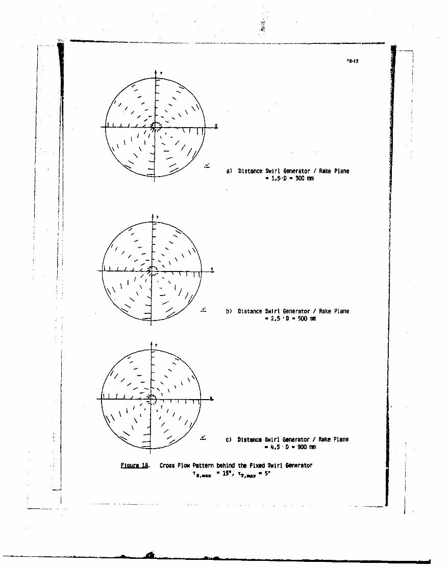
Some of the results are presented in fjjSa to 19. The flow pattern for the swirl com-bination T S#MAX - 150, 1 T,MAX a 5* 1n0-t04 distance between swirl generator and measuringplane of 1,5 D is shown in fq4a. According to the design of this swirl generatorthere is a clockwise cross aowwth one swirl center caused by the dominating bulkswirl. For different distances between swirl generator and measuring plane very similarcross flow patterns were measured behind this swirl generator (see fig.18b and 18c).This means that the generated swirl configuration and also the magnitude of the-lowdeflection is tolerably stable. Regarding the locations of the swirl center in each ofthe flow patterns it can be found that the swirl center is clockwise turning around the
center-line with increasing distance of the measuring plane.In f the cross flow pattern of the pure twin swirl is shown. The counter-rotating
doubleswirl can clearly be recognized being symmetrical with respect to the y-axis.
In fig.20 the flow deflection curves along the x-axis resulting from the theoreticaltwin swirl model (see Chapt. 3.1), the geometrical blade exit angles, and the measured
values are shown. According to the desired cosine-shaped flow deflection of the theoreti-
cal swirl model the trailing-edges of the guide vanes had to obtain a corresponding
contour. However, it was not possible to realize this contour because of manufacturingproblems. Thus guide vanes were built with linearly approximated contours at the trailing-
edges assuming zero deviation. A comparison of the measured values with the desired flow
distribution shows that the desired magnitudes could not be generated close to the
theoretical maximum and minimum flow deflection. Nevertheless the tendency of the
distributions is comparable even though further research in this subject seems to be
necessary. New considerations should take into account also the deviation between the
geometrical blade exit angles and the real flow angles.
MOVEABLE SWIRL GENERATORIn order to investigate the flow deflections behind the moveable swirl generator
the oil flow technique as well as 5-hole-probes were used. Wall flow pictures applying
the oil flow technique were produced for several angles of attack, varying measuring
plane distance and mass flow rate according to the following test programs
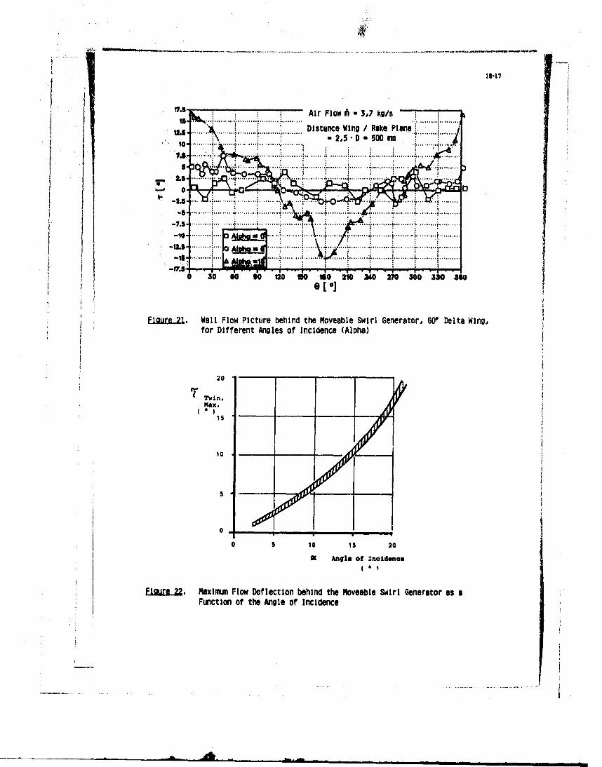
Some of these results are shown in fic.21 and fig.24.
The flow deflections at the wll are shown in aa function of the circum-ferential position for three anles of attack (0, 6, 19Sdegrees). A comparison of thethree curves emphasises the augmentation of the flow deflection by increasing the angleof attack. This increase of the maximum flow deflection at the wall depending on theangle of attack is shown in ftu,2. It results from the development and augmentationof the vorex shoson the upper sorface of the delta wing.
In order to gain confidence in the oil flow technique a comparison was done between
the wall flow picture obtained by the oil flow technique and the distribution of the flowdeflection measured with the S-hole-probes at 9St-radius. The result is shown in U9.23.both curves agree well. This shows that the oil flow technique is a good tool for measur-ing the flow deflection at the wall and can save effort and cost. In addition a cosine-distribution is plotted which describes the theoretical flow deflection at the wall fora pure twin swirl. It can be seen that the locations of the maximum and minimum flowdeflection and the zero passages are coinciding well, but between these locations themeasured and theoretical distributions show a distinct difference which may be attributedto this type of swirl generation.
In order to show the vortex sheets the measurement of the whole flow field behind
the moveable swirl generator Was carried out at an angle of attack of 150 and a distancebetween swirl generator and measuring plane of 2,5 D and resulted in the cross flowpattern shown in fig.24. Similar to the flow field behind the fixed swirl generator forthe pure twin swirl7lsee fig. 19) the two symmetrical counter-rotating swirls can clearlybe perceived. A comparison of the two swirl patterns shows that behind the moveablegenerator the swirls are more concentrated around the swirl centers while the fixedgenerator produces a flow deflection which is spread over the whole cross section.
5. FULL-SCALE INVESTIGATrONS
General Test Arrangement and Testing Technique
The model investigations described in the previous section were preliminary testsfor the full-scale simulation of intake swirl. The full-scale investigations consistof engine tests which are in preparation at this time. The object of these tests is togot more information about the influence of different types and magnitudes of swirlconfigurations on the engine behavior under static conditions.
The tests will be conducted in the engine test facility of the Jet PropulsionInstitute at the Universitit der Bundeswehr MUnchen. The test facility is designed forturbo jet engines up to an maximum thrust of 30kN and a maximum mass flow rate of 60 kg/s.A side view of this facility is shown in ftg.25.
The test facility containing intake splitters and primary and secondary air intakesilencer provides a smooth air flow for the rig-mounted engine inside the test cell whichis 4,5 m wide, 13,4 m long and on the average 6,2 m high. In order to reduce the tempera-ture of the exhaust jet it is mixed with cold secondary and tertiary air before it passesthrough the exhaust silencer.
As a test object a Larxac 04 turbofan engine was chosen which is used as propulsionin the Alpha Jet aircraft. This twospool engine features a two-stage fan (wLpC - 2.3,
-" 17000 1/min), a four-stage high-pressure compressor (w - 4,6 , . 22750lmn), each driven by a single-stage turbine, and a fixed-ariKCexhaust noVe. The totalmass flow rate is about m - 28 kg/s, the bypass ratio 1.13:1, and the maximum thrust about13,2 kU for sea-levol static conditions.
Although no intake swirl distortion ocoures at the practical application of thisengine it ts well suited for these investigations because of the absence of inlet guidevanes which have normally a flow straightening effect.
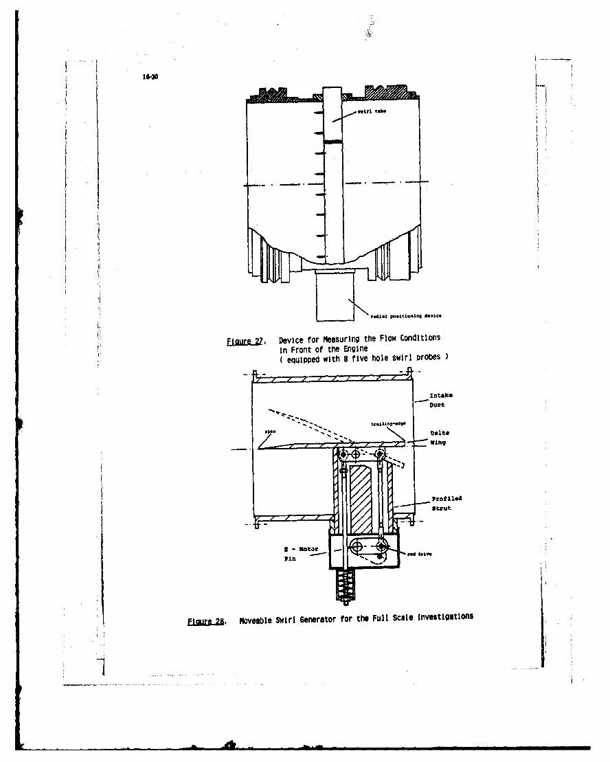
The main components of the test setup are shown in f . The original intake con-figuration designed as a bellmouth inlet had to be extendedby a swirl generating unitand a measuring device which allows the measurement of the flow field over the whole crosssection in front of the engine. This measuring davice consists of a swirl rake mounted ina rotable intake segment (soe .g 21). The swirl rake is designed as a diagonal strutwhich can be traversed in radial direction. Thus the intake segment needs only be turnableby 1800 in order to sweep over the whole cross section. In order to allow rotation it iscarried and guided on six rollers in two guide-rails. It is plugged up very carefullyagainst the non-moving intake parts. The swirl take carries eight 5-hole-probes which hadto be calibrated very carefully in built-in condition .
The first full-scale investigations will be carried out with a delta wing as a swirlgenerator /9/. This delta wing and its fastening inside the intake (see fig2l_ ) is go-metrically similar to the subscalc model used at the previous wind tunnellests (fv.16).The variation of the angle of attack is carried out with the help of a rod drive. A springis used to turn the delta wing quickly back into the starting position in case of surge ofthe compressor. In this case the driving mechanism can be disengaged very quickly. Thesystem is designed for continuous variation of the angle of attack up to a maximum of 250.
In order to obtain a fully developed swirl the measuring plane has to be at a dist-ance of about 1,5 D behind the swirl generator according to the modsl test results. [
18-7
6. CONCLUSIONS
On the basis of a detailed investigation of the engine inlet flow pattern behind atypical sup rsonic iitako of a military fighter aircraft it baa been shown that alsowirl distortions have to bensidered as dominant influencQ parameters on engine per-formance and intake/engine compatibility. Two basic types, i.e. twin swirl and bulk swirland also combinations thereof had to be onsidered. Nodal tests with fixed and moveablegenerators have proven their ability to reproduce those swirl distortions, and theyshowed ood agreement with the target patterns. The engine performance investigationswith full scale generators will be performed with a Lareac 04 low by-pass engine in theengine test facility using comprehensive instrumentation for flow field measurements inthe inlet duct as well as engine performance measurements.
7. REFERENCES
/1/ Aulehla, F.Intake Swirl - a Major Disturbance Parameter in Engine/Intake CompatibilityICAS/AIAA, -82-4.8.1, Seattle, August 1982
/2/ Detra, R. W.
The Secondary Flow in Curved PipesThesis, ETH ZUrich 1953
/3/ Lecht, M., and Weyer, H. B.
Unsteady Rotor Blade Loading in an Axial Compressor with Steady-State InletDistortionAGARD CP 248-30, Cleveland, Oct. 1978
/5/ Stocks, C. P., and Bissinger, N. C.The Design and Development of the Tornado Engine Air IntakeAGARD CP 301-10, Toulouse, May 198,
/6/ Staudacher, W.
Auslegung aines Delta-FiUgelsMBB-LKE 127, 1985
/7/ Hummel, D., and Srinivasan, P. S.Vortex Breakdown Effects on the Low-Speed Aerodynamic Ch3racteristics ofSlender Delta Wings in Symmetrical FlowJ. Royal Aero.Soc., Vol.71, 1967, pp 319-322
// Hummel, 0.On the Vortex Formation over a Slender Wing at Large Angles of IncidenceAGARD CP 247, 1978
/9/ Pazur, W.Entwurf siner Drallsimulationsemnrichtung vor dem Triebwerk Larzac 04UniBw-MUnchen, Institut fUr StrahlantriebeDiplomarbeit Nr. 86/11, 1986
ACKNOWLEDGEMENT jThe work reported herein was performed within a collaboration project between
M9 M*(Inchen and Universitit der Bundeswehr MUnchen and was supported within researchprogrammes of the German undesministerium der Vertaidigurtg. The permission to publiihthe results in greatly acknowledged.
24kms3 31
I avardiaberMS2 - maillary air Intak doos (MID)3 -bundarywr diverter
Figure 1. Tornado Inlet Geometry
bWM entrv bend exit
R 1,Tmax
0,Of 1,2 10
WI/iu 1,14
Figure 2. Comparison of Computed (Solid Lines) and MeasuredTwin Swirl (Dashed Lines) in a 210 Bent Pipe.Lines of Constant Axial Velocity Ratios;W - 1,6 rn/si Ref.2
Engine RtationL Centrifugal
Forces
L.E.coW1Low Energy Flow Low Energy Flow(SeparatintCOI (Sepaation at Third Ramp)
al Subbonic~fgh b)lHigh Superson4cLowIncidence IcidencefFigure 3. Generation of Intake Swirl, Ref.1
18-9
e Streamlines -
Circumn-
o Ube 3WO ference
Bulk Swirl Twin Swirl Circumferential FlowAngle : at Ra Const.
Eliure ., Superimposing of Bulk and Twin Swirls
tt
aI N o nI V r I IA
PONT mug MSS1F III II1 M
emwe
Fiur. Tornado Inlet SS* rl at Htuh Ilgle of Attack(Subsonic Flight) ,Ref,5
-- *..........
18-10
nama --IA
soearl Flea In laid* at KS3.tIC PWed, oele 0111 UII Mele
as
eacagi 3M M OR
aon in;iIIts
(SupersM. I onfigt ,Re5
RAMP
11*COWL (Part (nickoil
iEeu . Effect of Incidence and Engine Eigur.jl Model / Full ScaleMass Flow on Mean Swirl comarison of Inta'. Swirl
(R - 0,87-PTAX) Re. at No It 0
18-11 -Diffuser Plenum Nozzle Vaial
Chamber Dut ngol
Swirl Test Cross
Generator Section
Flow Dir.
orifice Plate ( Wall Pressure(/) Static Pressure
2 Upstream and downstream of the orificePrandtl Probe
WallWell Pre...ur.Total Presure andThermocouple
Wll Pre SureFive Hole Swirl Probesand position motor for remote control,
Air Flow
Figure 9, Arrangement and Instrumentation of theLow Speed Model Wind Tunnel
Bhaftd~mwter - lOmm
Profiled Shaftlength - 6mm)thickness- 4mm)
Read of the rive HoleSwirl Probe
1,111
FLure 10. Five Hole Swirl Probe
I
18-12 F
IIT
EIaure 11. Theoretical Model for Bulk Swirl
JFlour 12a. Theoretical Model for Twin Swirl,Flow Deflection Along the x-Axls
Fijgure 12 . Theoretical Model for Twin Swirl
18-131
Figure M Model Fixed Swirl Generator for Simulationof Swirl CombinationTB,max - 15" TT,max 50
ItI
EigureI. Model Fixed Swirl Generator, Twin SwirlS,== -200
_] ... .. .... ........ .. .I4
18-14
Elagt.5. Vrtexvortisonoe
Deltaelt Wiging.7
ShIrp-Ede Fastenin an4 Mehaim:o
Positioning of the SubscaleMoveable Swirl Generator
Figure 16, Geometry of the Model Delta Wing -Moveable Swirl Generator-
a) Distance Swirl Generator /Rake Plane-1,5-D p300111
7 b) Distance Swirl Generator /Rake Plane-2,5 -D -500 mmn
c) Distance Swirl Generator / Rake Plane-4,5 D - 900 mu
.......... ~-2, D.... ....... 50 . ..... r ....m.....
--W1r2~ Coprn o f the Mesuemn ..c... ue 4 ... il.. Flow... Picture......Five Hole Swr
Probes .
Geneator Det Win tv
11-19
eakant elSlencer
Flaure .2. Side View of the Engine Test Facility
owirlIs"Naorm"suring section
Figure 2fi. Test Arrangement of the Full Scale investigationis
tadial posItoing devig,
Figure.Z Device for MeasurIng the Flow Conditions'in Front of the Engine
equipped with 8 five hole swirl probes
- -~ trllstrut
Finug2. Moveable Swirl Generator for the Full Scale Investigationsa
~18-21
DISCUSSION
rtP.LmR , Frflow do the distortions caused by a fixed twin-swirl generator and a moveable-swirl generator compare and which onedo you think would give the beat simulation of the actual distorted flow in the intake of an engine in the same flight case?I am &Lid about distortion and turbulence.
Aulm's ReplyWe could not find turbulence during our test but we have started only with model tests. The engine tests will be carriedout in the Immediate future.
PbiOtamtt, FrThe first part of my question was: which kind of swirl generator would you prefer?
Auther's ReplyWe started with the moveable one, the delta wing.
M.Dupd&fGeCould you say something about the pressure loss of the different kinds of swirl generators, especially the circumferentialdistribution of the loss?
Author's ReplyWould you like to have the distortion values? The DC(60) for tht moveable-swirl generator is less than 0.1. About 0.05or 0.06, I do not know exactly at the moment.
R.G.Hercock, UKDo you propo'e to test the engine with total-pressure distortion as well as swirl? If so how are you to generate it?
Author's ReplyAt first we will start with swirl generators only, as it was our clear intent to investigate the two disturbances separately.That is, we simulate either swirl or pressure distortions measured for a typical case in the real inlet flow. In order to getthe engine response (surge) either the simulated disturbances will be increased (proportionally) or the engine will bemade more surge prone, eg by reducing the throat of the thrust nozzle. The simultaneous simulation of swirl andpressure distortion may then not be necessary, but could be accomplished as outlined in Reference I.