Design of a clock synchronisation sub-system for parallel embedded systems M. Fleury A.C. Downton A.F. Clark H.P.Sava Indexing terms: Clock synchronisation, Parallel embedded systems Abstract: Software tools are being developed to support a design methodology specific to parallel real-time continuous-dataflow embedded systems. The authors describe the design of a global clock sub-system which is an essential component of an event trace tool. A new amalgam of algorithms is proposed which attends to the trade-off between clock accuracy and the need to restrict disturbance of the application whilst recording traces. The details of an implementation on a hybrid parallel processor, as well as the results of tracing applications in the given problem domain, are included. 1 Introduction Real-time, continuous-dataflow embedded systems are an important class of engineering system for which par- allel solutions have much to offer. Examples of such systems can be found in vision [l], radar [2], speech processing [3] and signal compression [4]. The algorith- mic complexity and irregularity of such systems means that compilers which attempt automatic parallelisation of computer code are unlikely to provide much support in the near future [5]. Instead, a common design meth- odology based upon pipelines of processor farms (PPFs) [6] has been proposed. It offers a single concep- tual design model which is capable of incorporating data parallelism, algorithmic parallelism or temporal parallelism within individual farms. The methodology addresses the requirement to parallelise systems com- posed of a number of independent algorithms; it can handle time, ordering, data dependency and feedback constraints; and produces incrementally scalable solu- tions. Achievable throughput, latency and upper bound speed-up can be determined by analysis of the original application code. The PPF design methodology addresses an intermediate level of generality appropriate for a particular domain of applications. It is not limited to a particular machine architecture or a particular 0 IEE, 1997 ZEE Proceedings online no. 19971 155 Paper first received 22nd July 1996 and in revised form 6th February 1997 The authors are with the Electronic Systems Engineering Department, University of Essex, Wivenhoe Park, Colchester CO4 4SQ, UK processor topology for each farm. A message-passing paradigm is assumed, but it is possible, and can be desirable, to emulate message-passing on a shared- memory machine. The methodology does, however, rely on central farmer processes distributing work, and on sets of worker processes which perform that work by some means. A high level application building block, a farm template, has been designed to speed up prototyping [7]. The template incorporates instrumentation to enable event-tracing. Event traces can be used to give confidence in the correct working of the application, and to facilitate performance analysis. Since the role of the worker process is passive in the PPF methodology, it is not appropriate for the worker to initiate tracing when it has reached steady-state. To provide event traces, a centralised clock synchronisa- tion system is therefore required. The amalgam of synchronisation algorithms intro- duced in this paper is intended specifically to support the PPF methodology, though adaptations to other systems are naturally possible. The main features of the algorithm set are: (i) an initialisation phase in which the drift of the sys- tem from real time is assessed centrally; (ii) averaging to achieve a system reference time; (iii) subsequent refresh signals at a predetermined inter- val so as to prevent drift from the system time; (iv) local correction of drift between refresh signals. Notice that our work is primarily a design which we have implemented, adapting existing algorithms for our purposes. For the clock mechanism, the essential component of a trace, we were able to provide a central mechanism capable of tightening the precision of the clocks by reason of global knowledge. If a communication harness with integrated trace instrumentation is designed for general use (such as PICL [SI), a client- server clocking system may be preferred, which makes the time-server a passive component. Though it is more flexible, a client-server system is a disadvantage for tracing, as it does not allow the pattern of synchronisation traffic to be controlled for the purpose of reducing perturbation of the application. Our system, which follows an internal standard, is not intended for hard real-time systems, in the sense that not meeting the time constraints to which such a system is subject is considered a fatal failure. For 65 IEE Proc.-Comput. Digit. Tech., Vol. 144, No. 2, March 1997
Transcript
Design of a clock synchronisation sub-system for parallel embedded systems
M. Fleury A.C. Downton A.F. Clark H.P.Sava
Indexing terms: Clock synchronisation, Parallel embedded systems
Abstract: Software tools are being developed to support a design methodology specific to parallel real-time continuous-dataflow embedded systems. The authors describe the design of a global clock sub-system which is an essential component of an event trace tool. A new amalgam of algorithms is proposed which attends to the trade-off between clock accuracy and the need to restrict disturbance of the application whilst recording traces. The details of an implementation on a hybrid parallel processor, as well as the results of tracing applications in the given problem domain, are included.
1 Introduction
Real-time, continuous-dataflow embedded systems are an important class of engineering system for which par- allel solutions have much to offer. Examples of such systems can be found in vision [l], radar [2], speech processing [3] and signal compression [4]. The algorith- mic complexity and irregularity of such systems means that compilers which attempt automatic parallelisation of computer code are unlikely to provide much support in the near future [5]. Instead, a common design meth- odology based upon pipelines of processor farms (PPFs) [6] has been proposed. It offers a single concep- tual design model which is capable of incorporating data parallelism, algorithmic parallelism or temporal parallelism within individual farms. The methodology addresses the requirement to parallelise systems com- posed of a number of independent algorithms; it can handle time, ordering, data dependency and feedback constraints; and produces incrementally scalable solu- tions. Achievable throughput, latency and upper bound speed-up can be determined by analysis of the original application code.
The PPF design methodology addresses an intermediate level of generality appropriate for a particular domain of applications. It is not limited to a particular machine architecture or a particular 0 IEE, 1997 ZEE Proceedings online no. 19971 155 Paper first received 22nd July 1996 and in revised form 6th February 1997 The authors are with the Electronic Systems Engineering Department, University of Essex, Wivenhoe Park, Colchester CO4 4SQ, UK
processor topology for each farm. A message-passing paradigm is assumed, but it is possible, and can be desirable, to emulate message-passing on a shared- memory machine. The methodology does, however, rely on central farmer processes distributing work, and on sets of worker processes which perform that work by some means. A high level application building block, a farm template, has been designed to speed up prototyping [7]. The template incorporates instrumentation to enable event-tracing. Event traces can be used to give confidence in the correct working of the application, and to facilitate performance analysis.
Since the role of the worker process is passive in the PPF methodology, it is not appropriate for the worker to initiate tracing when it has reached steady-state. To provide event traces, a centralised clock synchronisa- tion system is therefore required.
The amalgam of synchronisation algorithms intro- duced in this paper is intended specifically to support the PPF methodology, though adaptations to other systems are naturally possible. The main features of the algorithm set are: (i) an initialisation phase in which the drift of the sys- tem from real time is assessed centrally; (ii) averaging to achieve a system reference time; (iii) subsequent refresh signals at a predetermined inter- val so as to prevent drift from the system time; (iv) local correction of drift between refresh signals. Notice that our work is primarily a design which we have implemented, adapting existing algorithms for our purposes.
For the clock mechanism, the essential component of a trace, we were able to provide a central mechanism capable of tightening the precision of the clocks by reason of global knowledge. If a communication harness with integrated trace instrumentation is designed for general use (such as PICL [SI), a client- server clocking system may be preferred, which makes the time-server a passive component. Though it is more flexible, a client-server system is a disadvantage for tracing, as it does not allow the pattern of synchronisation traffic to be controlled for the purpose of reducing perturbation of the application. Our system, which follows an internal standard, is not intended for hard real-time systems, in the sense that not meeting the time constraints to which such a system is subject is considered a fatal failure. For
instance, in avionics systems making use of the MIL- STD-1553B protocol [9] for a back-plane bus, message tags may be time-stamped by a hardware clock. For the importance of time handling in real-time systems refer to [lo].
If global time is not kept consistently when timestamp- ing a record of events in a multicomputer application, then the ordering of significant events on different nodes (i.e. usually processors) can easily fail to keep the correct global order. In particular, if the ordering of communication events is lost then the phenomenon of ‘tachyons’ occurs in which a message apparently arrives before it is sent [Note 11. Solutions exist in which logi- cal clocks [ l l , 121 are kept, but these involve time- stamping each message. Such systems are applicable to distributed systems, or where debugging is a goal [13]. Fault-tolerant solutions [ 14-1 61 typically involve O(n2) messages for n processes even if all message journeys are confined to a single hop. In [17] an O(n) message solution relies on the presence of an embedded ring topology, which excludes tree-topologies, though these are a natural topology for the data-farming applica- tions of concern to us. Other work [18], though impor- tant theoretically, relies on complete graphs. Finally, statistical post-processing of the trace record [ 191 repre- sents an alternative approach.
A method involving interpolation between start and end timing pulses [20] was initially explored but, though suitable for gauging intra-node process activity, was not found to be sufficiently accurate. A number of convergence algorithms [21, 221 exist but these may not provide accurate timing at the beginning of an algo- rithm. However, unlike distributed or networked meth- ods [23], it is possible to have an initial traffic-free phase; and one can assume that faults are rare, allow- ing a centralised algorithm.
A criterion for a portable design is that one should aim to avoid a solution involving low level manipula- tion of the hardware, as for instance in the synchro- nised wave solution for transputers of [24].
The requirements of the centralised, portable design can thus be summarised as: (i) A minimum of user intervention is needed in regard to the clocking mechanism. (ii) The design should not be dependent on any feature of the hardware such as would, for example, necessitate the use of assembly language. Solutions involving hard- ware interrupts [25] are by no means trivial to imple- ment, and equally run into the problem of application perturbation. (iii) The number of synchronisation messages should be minimised. (iv) The mechanism should not rely on a particular architecture. (v) It should not be assumed that the system is already in steady-state or can converge slowly to synchronisa- tion. (vi) The times should conform to a suitable real time reference. (vii) In practice, two algorithms are required: an algo- rithm to bring the clocks on all nodes within some min- Note 1. In astrophysics, a tachyon is a particle that appears to travel faster than the f i t e speed of light
66
imum error range, and, subsequently, an algorithm to maintain time against clock drift.
3 The processing model
3. I Processor requirements The method described below is suitable for processor nodes with at least two levels of priority and support- ing internal concurrency, as is common for interrupt- driven applications. The highest level of priority is needed to ensure minimum delay in the time service. Only local physical clocks are assumed to be available (most multicomputers can provide high priority monot- onic clocks with a resolution of at least 1 ps). An inter- mediary process which acts as a monitor able to intercept communication messages before passing the messages on is assumed in the model; the provision of the monitoring process would be an implementation- dependent feature.
One use of event traces is to provide input to a visu- aliser, the effective role of which is to reduce the quan- tity of trace data to a manageable size. Current visualisers, when faced with applications of varying time duration or communication intensity, may be lim- ited by the display rate of the graphics terminal, but this does not mean that as high a resolution as possible should not be aimed for. Event traces may also be post-processed as input to an execution-driven simula- tion or an analytic model. In [26] there is an appropri- ately accurate method of supplying a global time reference, which was aimed at hypercube multicomput- ers. However, on its own, this method only completely resolves communication events. Additionally, it is important for a trace mechanism with wide usage (though within the real-time PPF environment) to pro- vide timestamps that are not biased by possible drift of the master clock. In particular, where interrupts occur real-time should be maintained. If real-time is not required then it will be sufficient to synchronise to an uncorrected master clock. (The whole system will drift at the same linear rate.)
3.2 local clock requirements Experimental evidence [27] shows that crystal clocks drift linearly if the temperature regime is constant, and that drift is small anyway (< 10-5) so that second order terms are neglected in the following. (For runs longer than a few minutes temperature oscillations may occur for transputer clocks [28], in which case second order correction terms offer one solution.) It is therefore assumed that for correct clocks the accuracy of clocks should be such that a bound to the error is given by (1 - f ) ( t - t’) 2z p 5 H ( t ) - H(t’ ) 5 (I + f) ( t - t’) i= p (1) wherefis the maximum clock frequency drift rate, t is a notional reference time (real time) such as universal time coordinated (UTC) [23], p is the discrete clock precision or resolution, H(t) is the reading of a clock at time t , and ( t - t‘) > p. To clarify our explanation, Table 1 summarises the notation used in this paper.
4 The synchronisation model
4. I Normal behaviour To help in our explanation, this Section assumes that the processing system has already reached steady-state. In particular, the appropriate time interval between refresh signals, R, the clock refresh interval, is assumed
IEE Proc -Coinput Digit Tech, Vol 144, No 2, March 1997
Table 1: Notation used in the text
Variable Definition
maximum clock frequency drift rate
precision or resolution of all physical clocks
measured offset of node i’s clock from node 0’s clock (at time t ) offset 0,corrected for drift from global real time
total measured round-trip time from node 0 to node i (at t ime t ) the apparent round-trip time to node i recording the start on the central clock and the end on the remote clock
median of the clock differences (at time t ) estimate of node 0’s drift rate (at time t ) clock refresh interval, between synchronisation pulses
estimated drift of central clock during roundtrip from node 0 to node i (at t ime t ) number of stages or hops in a message’s outward journey
theoretical minimum one-way journey time over h hops theoretical error in the estimate of 0; theoretical error in the estimate of the difference in clock rates (the skew-rate)
the sampling interval used to establish R
to have been established. Section 4.2 details the calcula- tion of the clock refresh interval.
node
node i measures time to correction adjusting by estimated clock drift
_________________--_ -*
I r(t lme os measured by node I ) t I
I I I I I
1
I I I I I I I inode 0’s: I ]estimate/
; fo r time I node 0 I
1 correction mess age giving offset +
median offset
4. - - - -_____________ +
Di measured by node 0
To(h) c- --* 4.---__+
To(h1 (minimum time over h hops1 Fig. 1 Synchronisation signal pattern
t o
Steady-state behaviour proceeds as follows: the cen- tral synchronisation server (CSS) on node i = 0 sends a request message to every other node by sending a syn- chronisation ‘pulse’, and in each case immediately receives back a reading for the arrival time of the ‘pulse’, as shown in Fig. 1. We refer to ‘sending the request messages’ as ‘polling’. The central node in each case records the time delay for the round-trip, as given by its local clock. The central node subsequently, and for every other node, makes the following calculations: (i) the time delay for the round-trip is adjusted to account for intervening drift of the local clock on the central node; (ii) the corrected round-trip time delay is halved; (iii) the apparent one-way journey time to the remote node r is found by subtracting the synchronisation
IEE Proc.-Comput. Digit. Tech., Vol. 144, No. 2, March 1997
departure time-stamp from the arrival time reading; and (iv) the difference between r and the halved, corrected, round-trip time serves as an offset estimate of the dis- crepancy between the central node’s clock rate and the remote node’s clock rate.
By using the mid-point of the corrected round-trip time as an estimate of the reading at the other node, the central node minimises its error in the long run. In other words, the mid-point is an unbiased estimator of the arrival time of the pulse (i.e. its mean approaches the mean of the population of round-trip times) [Note 21.
Formally, the offset estimate at time t for node i (i = 1, 2, ..., n), n being the number of nodes, is
0i = (D; + c;)/2 - T i (2) with Di the total round-trip time to node i recorded on the central node. ci, the correction to the central node’s recording the round-trip time to node i, will be further explained in eqn. 4. ri is the interval between sending the pulse as recorded on the central node and receiving the pulse as recorded on node i’s clock when the pulse arrives.
There is no reason to give special significance to the central node’s clock. Therefore, offset oi is further adjusted to account for the departure of the central node’s local clock from some view of real time. A view of real time can be arrived at by an averaging procedure applied to the drift of all clocks. The average of the differences is found at each polling time t. In part, so as to reject outliers, particularly if the algorithm could also be adapted for times close to boot-up time, the median was chosen as an average. Alternatively, the mean of the middle could be used, but this would require sorting the differences, time complexity O(n log n), in order to find the middle set of differences. In [29] the mean of the centre is taken, by requiring all readings in the centre to be within 4~ + 2fR of each other, where E is the uncertainty in the message delay. In general, the selection algorithm for the centre is not trivial. The procedure in [29] is intended to remove from consideration the occasional clearly faulty clock, and as such the value of E is taken to be To, the known minimum one-way journey time. If a way of using a tighter value for E were to be found there is still the possibility that the precision of the global time estimate could be reduced if too many differences were rejected.
Once the median m(t) is calculated, it is added to the offset for each of the nodes, so that the final offset is
02 = 02 + m(t) (3) On the central node the offset is simply m(t). By recording successive median estimates, the central node is able to estimate the drift of its local clock:
(4) m(t + R ) - m(t)
R where again R is the clock refresh interval. Given this estimate, then ci = Dido. Node 0 can correct its local clock for drift by means of do.
Note 2. Were a priori knowledge available on a skew in the ratio of out- ward to return-trip journey Ones, then another point than the mid-point could be taken. However, bear in mind that measurement of a skew implies a hardware timer which would obviate the need for software tim-
do =
ing.
61
Node 0 sends the median-adjusted offsets { Oi} to the nodes. On receipt of its offset, each node additionally corrects for the drift in its time since the synchronisa- tion pulse was sent. This node drift correction uses the same method as described for local clock adjustment in Section 5. Drift corrections are assumed to be by soft- ware means, as normally a node would not be able to alter its local physical clock. The polling is repeated by the central node after clock refresh interval R.
Using the median of the clock differences rejects outliers but does not rely on a priori knowledge to reject them. It makes no assumptions about the nature of the aggregate message round-trip time distribution. Other methods that have been employed or suggested to increase the accuracy of readings include: using a recursive estimate of the round-trip time with a linear smoothing function [27]; and rejecting long delay times as these are more likely to include asymmetrical journeying times [30, 311. These solutions rely on convergence of local clocks to a global time, whereas for event tracing the accuracy must be within guaranteed bounds at a time signalled from the central farmer. This contrasts with toolkits that allow a trace to be initiated when a process ascertains it has reached a steady state. Note that for cooperative algorithms, using the median may be unsuitable since no new value is introduced [22] and convergence is therefore not guaranteed.
The calculation of the median is not computationally intensive if we can employ [32]:
(5) 2 x z - x m
t=1 IX% - Xml = o
(with n data values x, having median x,) to form an iterative and logarithmically convergent equation, i.e.:
2%
(6) - X=l lx,-xmk I
c:=1 lx,-xmk I X m . k + , - 1
(Other algorithms are at best O(n log(1og n)) [33].) The situation is better than this: since we only estimate the true median, we need only make a few iterations. The possibility of ill-conditioning may make it necessary to curtail the iterations anyway. An advantage of using a median-adjusted correction term, particularly if the clocks were not to be brought together by the initialisa- tion phase, is that the correction jumps on each clock are reduced in aggregate. The possibility of global time appearing to jump forward abruptly or even move neg- atively is reduced.
4.2 Establishing the refresh interval Since there is uncertainty in the estimate of the clock offset and clock drifts relative to a central reference, it is necessary to refresh the clocks by periodic synchronisation pulses. Unlike some other systems, the method used here does not seek to keep track of when to refresh each individual node with a separate synchronisation pulse (or allow each node to request a synchronisation from the central server). Instead, the clock refresh interval R for all nodes is chosen as min({R,}). An advantage of a single clock refresh interval is that all synchronisation pulses are sent at the same time, and not at irregularly-spaced intervals.
For simplicity, consider the refresh time R necessary to ensure communication events are correctly ordered between the central node and one other node [26],
68
which is given by
(7)
where To(h) is the minimum possible one-way message time with O(0) data, and h is the number of message hops. In a single bus system h = 1, but for our multi- computer (Section 6 ) employing store-and-forward communication h 2 1. ed is the error as recorded by a notional global clock in the offset estimate of eqn. 3 (caused by the variance of round-trip timings). An upper bound for ed is given in eqn. 8. The number er is the error as calculated from a notional global clock in the skew-rate estimate. The skew is between the clock rates of the two nodes. An upper bound for ef is given in eqn. 11. R is the minimum time taken for the clocks to drift apart to such an extent that a message between any two nodes might result in an ordering error. An ordering error would occur if a message were to be recorded as arriving before it was sent. The factors of two in eqn. 7 arise because if the uncertainty between the central node and a subsidiary node is e, then the uncertainty in timing between any two subsidiary nodes, were they to pass a message, is 2e.
To can be estimated by a message-timing measure- ment of the intended computer system when no other message-generating applications are present. A long- tailed distribution of round-trip times is common to LAN networks [34] and multicomputers [26] alike. It follows that any one attempt at measurement of To is most likely to occur at the most populated end of the distribution of To measurements. The clock difference error is bounded for any one node by
ed < (oz/2 - TO(h))(l + fi) + p + fzTO(h) (8) f, is the relative clock drift between node 0 and node i. D,/2-T0 (h) represents the uncertainty in the h hop jour- ney time to node i were the clocks at node 0 and node i running at the same rate; (I412 - To(h)>f, is the addi- tional error due to clock skew, andf,T,(h) is the uncer- tainty in node 0’s measurement of the minimum journey time to node i. For the purposes of tracing one can make do with an estimate of To(l) rather than keep a table of estimated minimum journey times indexed by h. f, is estimated by:
Oi(t + S) - Oi(S) S f i = (9)
where O,(t) is the measured clock offset at time t , as given by eqn. 3, and S is a suitable sample interval. The maximum error e, that can be made is:
where f, is the maximum frequency drift rate for one clock, substituted forf, into eqn. 8 in order to arrive at eqn. 10. Notice that iff, is the maximum frequency drift rate for any one clock, the total possible drift is 2f,. In fact, eqn. 10 is the same equation for maximum clock reading error as that developed in [34] by a dif- ferent route and for a different purpose. The maximum possible error is determined by the maximum round- trip time which naturally arises, as the synchronisation method depends on message passing. An upper bound to the error in the frequency drift can also be arrived at:
2ed ef < - S IEE Proc.-Comput. Digit. Tech., Vol 144, No. 2, March 1997
Though one might estimate the S needed for a required ef (by estimating ed for each subsidiary node through comparing successive values of 0,) this would mean that S might cause an arbitrary delay at the beginning of a test in order to bound ef sufficiently. A simple expedient of not allowing ef above a characteristic data-sheet value for f, ensures that accuracy is preserved at a small cost to efficiency. A lower bound on S is that its duration should not be so short that successive measurements are not statistically independent.
Eqn. 8 relies on a measurement of D, to bound the reading error. If the same refresh pulse is used for all nodes then the maximum error that can occur is sought: this will arise from the maximum journey time. However, if successive sampling rounds are made to find the maximum journey time, then the minimum maximum journey time may be selected. If the probability of finding a low enough value from any one round of samples is p , then the probability that waiting time will be k rounds before finding that value is p( l-~)~-l. The expected number of Bernoulli trials (including the successful trial) to achieve a low enough value is
- 1 2 1 = -
P with variance
If one estimates that the probability of not getting a low enough value is 0.5, then XI is two. We need to include at least CT extra trials to account for the error in the estimate, which is approximately four trials in all. The distribution of round-trip messages can also be examined to estimate the number of rounds necessary. Certainly, sufficient samples should be taken to bracket any system interrupts.
5 Local clock adjustment
The method outlined in Section 4 does not correct for the drifting of local clocks between the synchronisation pulses. For generality, a software correction method is described, though on some machines it is possible to correct by hardware means, (for instance, phase-locked loops on Internet machines serviced by the Network Time Protocol [31]). Each local node can estimate its clock drift relative to the averaged real-time, by finding the change in physical clock offsets over a number of synchronisation rounds. Since drift is assumed to be linear, two observations are sufficient. A linear correction function ensures smoothness, avoiding discontinuities [24].
In Fig. 2a, node i’s local physical clock is shown drifting from global time in a linear fashion. However, in practice, offset adjustments are made to a local soft- ware clock, Fig. 26. If a local time enquiry is made, the returned value is the sum of the software clock time at the latest synchronisation instance and the time interval measured on the physical clock. Therefore, this returned time will be in error by the amount marked ‘local error’ in Fig. 2b.
L ( t ) = H,(sA)+(A,(k)+l)(H,p(t)-H,p(Sk)),t > S A (14) where L,(t) returns the local time for node i adjusted to
Formally
IEE Proc -Comput Digit Tech, Vol 144, No 2, March 1997
t I
E l P n, node i ’s local
.I./ 4 error c /’ -global
4 * clock sync. interval R time
b Fig. 2 Local drift on physical and software clocks U Physical clock, h Software clock
Adjusting a local clock reading between synchronisa- tion pulses by means of a linear correction function does not require regularly-spaced synchronisation inter- vals, and it will tolerate a time lag between the arrival of a synchronisation pulse and the arrival of offset Oi(t>.
5.1 Simplification of the design In some cases it is possible to implement clock synchro- nisation for our application domain without some of the features described. For example, local clock adjust- ment is not required if message events are the only timed events. Similarly, if no reference is made to events outside the system, then difference averaging is not needed. However, the opportunity was taken to provide a complete general solution by software means so as to anticipate future needs.
6 A case study: Implementation on the Paramid multicomputer
Our system is in a development stage. This Section presents a preliminary case study, but further imple- mentations will be necessary to validate our approach. In particular, an implementation for a larger number of processors would be needed.
69
\ \ \
‘\
Fig.3 VCS: virtual channel system RTE: run-time executive CSS: central time server LTS: local time server
System set-up on the Paramid with a PPF arrangement
6. I The system set-up The Paramid [35] is a transputer-based machine, each transputer being equipped with a computational accelerator, the i860 [36]. We used an eight-module machine. In our system, the transputers run at a nominal 30MHz, the superscalar i860 at 50MHz, and the transputer communication links were set at 20MHz. The transputer [37] has a small hardware stack which is manipulated by a firmware scheduler to provide optimal context switching of threads. In the transputer literature, threads are commonly called processes. There are just two process queues (and two associated timer queues), representing high and low priority processes. High priority processes on the transputer interrupt low priority processes, and run until blocked by communication or they are self- descheduling. As high priority processes do not interrupt themselves, other high priority processes should be of short duration. Fig. 3 shows the physical arrangement of processors, as well as existing system software including the servicing of run-time I/O. An intermediary process acting as the interface between the transputer and 860 by means of shared-memory could, and was, conveniently used as a monitor process. On other transputer-based machines a monitor is typically provided by reversing the direction of communication channels and triggering traces by the alt indeterminate command [24]. The CSS was run at high priority, as were the local time servers, so as to provide a rapid
70
I
response. The CSS also provided local time for its node. Before descheduling, the CSS issues a request for a re-awakening after clock refresh interval R, whereupon the CSS is placed on the high priority timer queue. Local time servers are immediately re-awakened upon arrival of a synchronisation pulse. (We did not take special measures to further reduce the normal latency of high priority scheduling which might be considered for real-time applications [24].) The manufacturer’s figures give a high priority latency between 3.9 and 2 . 9 ~ were the transputers to be run at only 20MHz, which is the raw data transmission rate of one of the transputer’s four links. The organisation of the Paramid was not ideal in this respect because, as the 360 ran more quickly than the transputer, it was necessary to give high priority to any process servicing the i860. For the purposes of making a trace, this did not affect message ordering. Because of the limited numbers of available processors, one of the nodes was placed in one test on the same processor as the synchronisation node. This should have distorted the results as the minimum journey time was less than the recorded one hop time, but in practice the message ordering on the visualiser was not affected.
The Paramid usually employs a virtual channel system but the underlying hardware is dependent on store-and-forward communication. Fig. 4 is the result of measurements on an empty system, when it will be seen that the round-trip message time distribution is
IEE Proc -Comput Digit Tech, Vol 144, No 2, March 1997
Table 2: Timings recorded on the central node using the local clock
5 0
U 4 0 - W . L:
E 30- J - e - 2 0 - ,\"
1 0 -
0
Wall-clock Sync. time interval
Sync. timings
16.641 3.197
32.125 3.197
47.452 3.197
109.040 3.197
155.096 3.197
309.957 3.197
9
13
18 37
52
100
Total % Mean overhead work time
4.987 0.1
2.745 0.2
2.034 0.3 0.822 0.7
0.640 1 .o 0.365 2.0
~~~~ ~ ~
All measurements are in seconds
indeed long-tailed, though the lower 'hump' may be caused by the low priority process time-slice interrupt (every 1 0 2 4 ~ ) which makes some readings appear longer.
6000
5000
LOO0
3000
U c W
P L
2000
1 0 0 0
0
Overhead from
Syncs. serving time
0.013 0.311
0.063 0.316
0.145 0.316
0.097 0.294
0.183 0.308
0.321 0.306
making trace
0.505
0.503
0.504
0.505
0.502
0.504
3 122 124 126 128 1 3 0 132 time, p s
Fig.4 Frequency of timings for one hop (round-trip) on the Paramid
job size, s Fig.5 Overheadfrom trueing on the Purumid
spacetime diagram
837 time 1349 Fig.6 Displuy for U seven worker farm
spacetime diagram
1966 time 2030 Fig. 7 Display of the postcode application
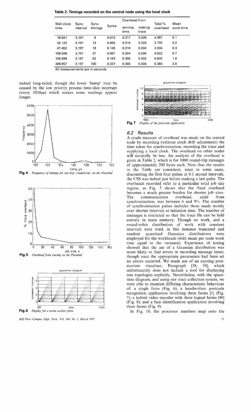
6.2 Results A crude measure of overhead was made on the central node by recording (without clock drift adjustment) the time taken for synchronisation, recording the trace and supplying a local clock. The overhead on other nodes will naturally be less. An analysis of the overhead is given in Table 2, which is for 1000 round-trip messages of approximately 200 bytes each. Note that the results in the Table are consistent, since in some cases, discounting the first four pulses at 0.1 second intervals, the CSS was halted just before making a last pulse. The overheads recorded refer to a particular total job size regime, as Fig. 5 shows that the fixed overhead becomes a much greater burden for shorter job sizes. The communication overhead, aside from synchronisation, was between 6 and 9%. The number of synchronisation pulses includes those made mostly over shorter intervals at initiation time. The number of messages is restricted so that the trace file can be held entirely in main memory. Though no work, and a round-robin distribution of work with constant intervals were tried, in this instance truncated and random quantised Gaussian distributions were employed for the workloads (with mean per node work time equal to the variance). Experience of testing showed that the use of a Gaussian distribution was more likely to find errors in recording message times; though once the appropriate parameters had been set no errors occurred. We made use of an existing post- mortem visualiser, Paragraph [38, 391, which unfortunately does not include a tool for displaying tree topologies explicitly. Nevertheless, with the space- time diagram, and using our trace collection system, we were able to examine differing characteristic behaviour of: a single farm (Fig. 6); a handwritten postcode recognition application involving three farms [l] (Fig. 7) ; a hybrid video encoder with three logical farms [40] (Fig. 8); and a face identification application involving three farms (Fig. 9).
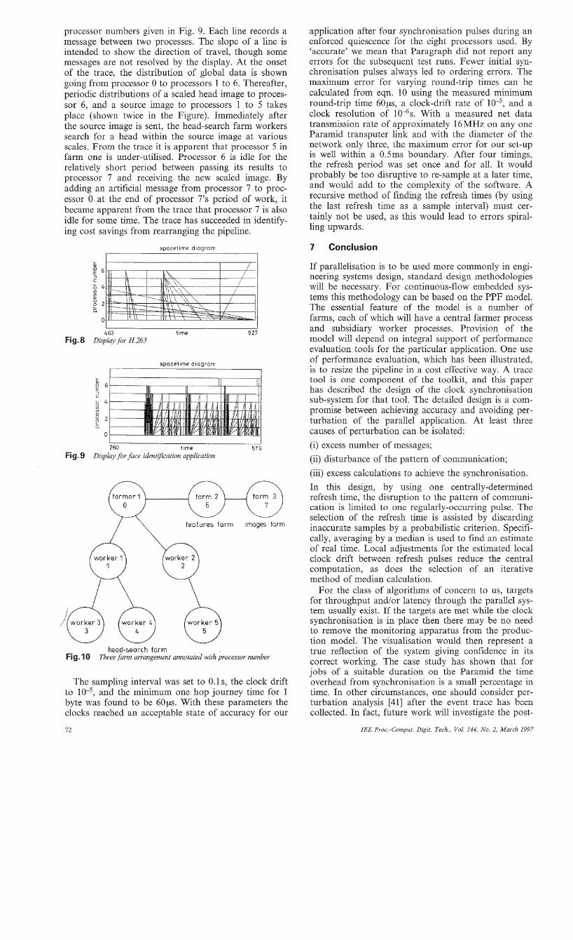
processor numbers given in Fig. 9. Each line records a message between two processes. The slope of a line is intended to show the direction of travel, though some messages are not resolved by the display. At the onset of the trace, the distribution of global data is shown going from processor 0 to processors 1 to 6. Thereafter, periodic distributions of a scaled head image to proces- sor 6, and a source image to processors 1 to 5 takes place (shown twice in the Figure). Immediately after the source image is sent, the head-search farm workers search for a head within the source image at various scales. From the trace it is apparent that processor 5 in farm one is under-utilised. Processor 6 is idle for the relatively short period between passing its results to processor 7 and receiving the new scaled image. By adding an artificial message from processor 7 to proc- essor 0 at the end of processor 7's period of work, it became apparent from the trace that processor 7 is also idle for some time. The trace has succeeded in identify- ing cost savings from rearranging the pipeline.
spacetime d iag ram
k " 6 s
g 2
& 4 In
a
0
463 time 527 Fig. 8 Display for H.263
spacetime diaqram
L al n 6
1 4 f :: 8 2 a
0
260 t ime 516 Fig. 9 Display for face identlficatwn application
farmer 1 farm 2 farm 3
features farm images farm
head-search farm Fig. 10 Three farm arrangement annotated with processor number
The sampling interval was set to 0.1 s, the clock drift to and the minimum one hop journey time for 1 byte was found to be 6 0 ~ . With these parameters the clocks reached an acceptable state of accuracy for our
72
application after four synchronisation pulses during an enforced quiescence for the eight processors used. By 'accurate' we mean that Paragraph did not report any errors for the subsequent test runs. Fewer initial syn- chronisation pulses always led to ordering errors. The maximum error for varying round-trip times can be calculated from eqn. 10 using the measured minimum round-trip time 60w, a clock-drift rate of and a clock resolution of 10-6s. With a measured net data transmission rate of approximately 16MHz on any one Paramid transputer link and with the diameter of the network only three, the maximum error for our set-up is well within a 0.5ms boundary. After four timings, the refresh period was set once and for all. It would probably be too disruptive to re-sample at a later time, and would add to the complexity of the software. A recursive method of finding the refresh times (by using the last refresh time as a sample interval) must cer- tainly not be used, as this would lead to errors spiral- ling upwards.
7 Conclusion
If parallelisation is to be used more commonly in engi- neering systems design, standard design methodologies will be necessary. For continuous-flow embedded sys- tems this methodology can be based on the PPF model. The essential feature of the model is a number of farms, each of which will have a central farmer process and subsidiary worker processes. Provision of the model will depend on integral support of performance evaluation tools for the particular application. One use of performance evaluation, which has been illustrated, is to resize the pipeline in a cost effective way. A trace tool is one component of the toolkit, and this paper has described the design of the clock synchronisation sub-system for that tool. The detailed design is a com- promise between achieving accuracy and avoiding per- turbation of the parallel application. At least three causes of perturbation can be isolated: (i) excess number of messages; (ii) disturbance of the pattern of communication; (iii) excess calculations to achieve the synchronisation. In this design, by using one centrally-determined refresh time, the disruption to the pattern of communi- cation is limited to one regularly-occurring pulse. The selection of the refresh time is assisted by discarding inaccurate samples by a probabilistic criterion. Specifi- cally, averaging by a median is used to find an estimate of real time. Local adjustments for the estimated local clock drift between refresh pulses reduce the central computation, as does the selection of an iterative method of median calculation.
For the class of algorithms of concern to us, targets for throughput and/or latency through the parallel sys- tem usually exist. If the targets are met while the clock synchronisation is in place then there may be no need to remove the monitoring apparatus from the produc- tion model. The visualisation would then represent a true reflection of the system giving confidence in its correct working. The case study has shown that for jobs of a suitable duration on the Paramid the time overhead from synchronisation is a small percentage in time. In other circumstances, one should consider per- turbation analysis [41] after the event trace has been collected. In fact, future work will investigate the post-
IEE Pvoc -Comput Digit Tech, Vol 144, No 2, March 1997
conferenceo; Distributed computer syst&“ IEEE, 1987, pp. 299- 306
8 Acknowledgement 20 OBELOER, W., WILLEKE,,H.,, and MAEHLE, E.: ‘Perform- ance measurement and visualization of multi-transputer systems with DELTA-T’ in HARING, G., and KOTSIS, G. (Eds.): ‘Per-
This work was carried out under EPSRC research con- formance measurement and visualization of parallel systems’
(queueing) mouei.
tract GR/K40277 ‘Portable software tools for embed- ded signal processing applications’ as part of the
(Elsevier, Amsterdam, 1993), pp. 119-143 21 MARZULLO, K., and OWICKI, s.: ‘Maintaining the time in a
distributed system’, ACM Operating Syst. Rev., 1983, 19, (3), pp. 44-54 EPSRC PSTPA (Portable Software Tools for Parallel
Architectures) directed Drograrmne. 22 RICKERT. N.W.: ‘Non Byzantine clock synchronization - a I ”
9
1
2
3
4
5
6
7
8
9
10
11
12
13
14
15
16
17
18
References
CUHADAR, A., and DOWNTON, A.C.: ‘Structured parallel design for embedded vision systems: An application case study’. Proceedings of IPA’95 IEE international conference on Image processing and its applications, July 1995, pp. 712-716 (IEE Con- ference Publication No. 410) EDWARD, M.N.: ‘Radar signal processing on a fault tolerant transputer array’ in DURRANI, T.S., SANDHAM, W.A., SOR- AGHAN, J.J., and FORBES, S.M. (Eds.): ‘Applications of trans- puters 3’ (IOS, Amsterdam, 1991) GLINSKI, S., and ROE, D.: ‘Spoken language recognition on a DSP arrav urocessor’. ZEEE Trans. Parallel Distrib. Svst.. 1994. 5, (7), pp.’6$7-703 ’ CHENG. A.-M.: ‘Hieh speed video compression testbed’, ZEEE Trans. Consumer Electron:, 1994, 40, (3), pp. 538-548 COFFIN, M.H.: ‘Parallel programming a new approach‘ (Silicon Press, Summit, NJ, 1992) DOWNTON, A.C., TREGIDGO, R.W.S., and CUHADAR, A.: ‘Top-down structured parallelisation of embedded image process- ing applications’, ZEE Proc., Vis. Image Signal Process, 1994, 141, (6), FF. 431437 FLEURY. M.. SAVA, H.P., DOWNTON, A.C., and CLARK, A.F.: ‘Designing and implementing a software template for embedded uarallel svstems’ in JESSHOPE. C.R., and SHA- FARENKO, A.V. (Ehs.): UK Parallel’96, (Springer, London,
GEIST. G.A.. HEATH. M.T.. PEYTON, B.W., and WORLEY, 1996), pp. 163-180
P.H.: ‘A user’s guide to PICL: A portable instrumented commu- nication library’. Technical report, ORNL/TM11616, Oak Ridge National Laboratory, Oak Ridge, TN, USA, August 1990 D’AVINO, D., and DELONG, C.: ‘MIL-STD-1553 protocol reorganised‘ (SAE International, 1996) LEVI, S., and AGRAWALA, A.K.: ‘Real-time system design’ (McGraw-Hill, New York, 1990) LAMPORT, L.: ‘Time, clocks, and the ordering of events in a distributed system’, Commun. ACM, 1978, 21, (7), pp. 558-565 RAYNAL, M., and SINGHAL, M.: ‘Capturing causality in dis- tributed systems’, ZEEE Comput., February 1996, pp. 49-56 LEVROUW, L.J., and AUDENAERT, K.M.R.: ‘Minimimizing the log size for execution replay of shared-memory programs’ in BUCHBERGER, B., and VOLKERT, J. (Eds.): CONPAR’94- VAPP VI, (Springer, Berlin, 1994), pp. 7G37 (Lecture Notes in Computer Science Volume 854) LAMPORT, L., and MELLIAR-SMITH, P.M.: ‘Synchronizing clocks in the presence of faults’, J. Assoc. Comput. Mach., 1985, 32, (l), pp. 52-78 SHIN, K.G., and RAMANATHAN, P.: ‘Clock synchronization of a large multiprocessor system in the presence of malicious faults’, IEEE Trans. Comput., 1987, 36, (l), pp. 2-12 SRIKANTH, T.K., and TOUEG, S.: ‘Optimal clock synchroni- zation’, J. ACM, 1987, 34, (3), pp. 626-645 DE CARLINI, U., and VILLANO, U,: ‘A simple algorithm for clock synchronization in transputer networks’, Softw.-Pract.
LUNDELIUS, J., and LYNCH, N.: ‘An upper and lower bound for clock synchronization’, Znj Control, 1984, 62, (2-3), pp. 190- 204
ExP., 1988, 18, (4), pp. 331-347
23
24
25
26
27
28
29
30
31
32
33
34
35
36
37
38
39
40
41
programming experiment’, ACM Operating Syst. Rev., 1988, 22, (l), pp. 73-78 KOPETZ. H.. and OCHSENREITER, W.: ‘Clock synchroniza- tion in distributed real-time systems’, ZEEE Trans. Comput., 1987, 36, (8), pp. 933-940 VILLANO, U,: ‘Monitoring parallel programs running in tran- puter networks’ in HARING, G., and KOTSIS, G. (Eds.): ‘Per- formance measurement and visualization of parallel systems’ (Elsevier, Amsterdam, 1993), pp. 67-96 JIANG, J., WAGNER, A., and CHANSON, S.: ‘Tmon: A real- time performance monitor for transputer-based multicomputers’ in FIELDING, D.L. (Ed.): ‘Transputer research and applications 4’ (IOS, Amsterdam, 1990), pp. 3645 DUNIGAN, T.H.: ‘Hypercube clock synchronization’, Concur- rency: Pract. Exp., 1992, 4, (3), pp. 257-268 COLE, R., and FOXCROFT, C.: ‘An experiment in clock syn- chronization’, Computer J., 1988, 31, (6), pp. 496-502 MAILLET, E., and TRON, C.: ‘On efficiently implementing glo- bal time for performance evaluation on multiprocessor systems’, J. Parallel Distrib. Comput., 1995, 28, (l), pp. 8493 GUSELLA, R., and ZATTI, S.: ‘Accuracy of the clock synchro- nization achieved by TEMPO in Berkeley Unix 4.3BSD’, ZEEE Trans. Softw. Eng., 1989, 15, (7), pp. 847-852 MILLS, D.L.: ‘On the accuracy and stability of clocks synchro- nized by the Network Time Protocol in the Internet system’, ACM Comput. Commun. Rev., 1980, 20, (l), pp. 65-75 MILLS, D.L.: ‘Internet time synchronization: The Network Time Protocol’, ZEEE Trans. Commun., 1991, 39, (lo), pp. 1482-1493 PRESS, W.H., FLANNERY, B.P., TEUKOLSKY, S.A., and VETTERLING, W.T.: ‘Numerical recipes in C‘ (Cambridge Uni- versity Press, UK. 1988), Edn. 1, pp. 476-479 KNUTH, D.E.: ‘The art of computer programming, volume 31 sorting and searching’ (Addison-Wesley, Reading, MA, 1973), pp. 216-220 CRISTIAN, F.: ‘A probabilistic approach to distributed clock synchronization’. Proceedings of the ninth IEEE international conference on Distributed computer systems, June 1989, pp. 288- 296 ‘The Paramid User Guide’. Transtech Parallel Systems Corpora- tion, 20 Thomwood Drive, Ithaca, NY, USA, 1993 ATKINS, M.: ‘Performance and the 860 microprocessor’, ZEEE Micro, October 1991, pp. 24-27, 72-78 GRAHAM. I., and KING, T.: ‘The transputer handbook‘ (Pren- tice-Hall, New York, 1990 HEATH, M.T., and ETHERIDGE, J.A.: ‘Visualizing the per- formance of parallel programs’, ZEEE Softw., 1991, 8, (5), pp. 29- 39 GLENDINNING, I., GETOV, V.S., HELLBERG, S.A., and HOCKNEY, R.W.: ‘Performance visualisation in a portable par- allel programming environment’ in HARING, G., and KOTSIS, G. (Eds.): ‘Performance measurement and visualization of parallel systems’ (Elsevier, Amsterdam, 1993), pp. 251-275 SAVA, H.P., FLEURY, M., DOWNTON, A.C., and CLARK, A.F.: ‘A case study in pipeline processor farming: Parallelising the H.263 encoder’ in JESSHOPE, C.R., and SHAFARENKO, A.V. (Eds.): UK Parallel’96, (Springer, London, 1996), pp. 196-205 MAHOLY, A.D., REED, D.A., and WIJSHOFF, H.A.G.: ‘Per- formance measurement intrusion and perturbation analysis’, ZEEE Trans. Parallel Distrib. Syst., 1992, 3, (4), pp. 433450