Page 1
DESIGN OF A HIGH ALTITUDE LONG
ENDURANCE FLYING-WING SOLAR-POWERED
UNMANNED AIR VEHICLE
A.A. Alsahlani, L. J. Johnston, and P.A. Atcli¨e
University of Salford
School of Computing, Science and Engineering
Salford, Greater Manchester M5 4WT, U.K.
The low-Reynolds number environment of high-altitude §ight places se-vere demands on the aerodynamic design and stability and control ofa high altitude, long endurance (HALE) unmanned air vehicle (UAV).The aerodynamic e©ciency of a §ying-wing con¦guration makes it anattractive design option for such an application and is investigated inthe present work. The proposed con¦guration has a high-aspect ra-tio, swept-wing planform, the wing sweep being necessary to provide anadequate moment arm for outboard longitudinal and lateral control sur-faces. A design optimization framework is developed under a MATLABenvironment, combining aerodynamic, structural, and stability analysis.Low-order analysis tools are employed to facilitate e©cient computa-tions, which is important when there are multiple optimization loops forthe various engineering analyses. In particular, a vortex-lattice methodis used to compute the wing planform aerodynamics, coupled to a two-dimensional (2D) panel method to derive aerofoil sectional characteris-tics. Integral boundary-layer methods are coupled to the panel methodin order to predict §ow separation boundaries during the design itera-tions. A quasi-analytical method is adapted for application to §ying-wing con¦gurations to predict the wing weight and a linear ¦nite-beamelement approach is used for structural analysis of the wing-box. Stabil-ity is a particular concern in the low-density environment of high-altitude§ight for §ying-wing aircraft and so provision of adequate directionalstability and control power forms part of the optimization process. Atpresent, a modi¦ed Genetic Algorithm is used in all of the optimiza-tion loops. Each of the low-order engineering analysis tools is validatedusing higher-order methods to provide con¦dence in the use of thesecomputationally-e©cient tools in the present design-optimization frame-work. This paper includes the results of employing the present optimiza-tion tools in the design of a HALE, §ying-wing UAV to indicate that thisis a viable design con¦guration option.
Progress in Flight Physics 9 (2017) 3-24 DOI: 10.1051/eucass/201709003
© The authors, published by EDP Sciences. This is an Open Access article distributed under the terms of the Creative Commons Attribution License 4.0 (http://creativecommons.org/licenses/by/4.0/).
Article available at http://www.eucass-proceedings.eu or https://doi.org/10.1051/eucass/201609003
Page 2
PROGRESS IN FLIGHT PHYSICS
1 INTRODUCTION
High-altitude aircraft §ying in the stratosphere (around 20 30-kilometer alti-
tude) can provide a useful platform for sensors to support a range of military
and civilian surveillance tasks. These can include real-time monitoring of seismic
risks or volcanic areas, early forest ¦re detection, border security surveillance,
pipe-line and power-line surveys, telecommunication services, agriculture moni-
toring, etc. [1]. By §ying at such high altitudes, the aircraft can see or cover large
geographical areas at wide angles and, in addition, the altitude o¨ers some pro-
tection in terms of possible interception by hostile vehicles. Although a number
of research and operational high-altitude aircraft have been developed (including
the Lockheed U-2, Helios, Zephyr, and Global Hawk) [2, 3], there still remain
signi¦cant challenges in the design and operation of HALE aircraft, particularly,
in respect to their payload capability.
To date, the majority of existing HA UAVs have been of conventional wing/
fuselage/tail/¦n con¦guration. There is currently research being undertaken into
the use of Blended-Wing Body con¦gurations for UAV applications because of
their perceived advantages in terms of aerodynamic and structural e©ciency [4].
A true §ying-wing is perhaps the most aerodynamically-e©cient aircraft con¦g-
uration but, to date, has not been investigated in any detail for possible appli-
cation to HA UAVs. Such a con¦guration would require a moderate amount
of wing sweep in order to generate stability in §ight and to provide adequate
control power for manoeuvring purposes. One objective of the present research
work is to investigate the design and optimization of a swept, true §ying-wing
con¦guration for application to HA UAV operations. A swept, §ying-wing con-
¦guration is to be studied for operation at these §ight conditions, designed to
meet a particular mission requirement. Speci¦c topics to be considered will be
development of a fast and accurate-as-possible multidisciplinary optimization
tool able to design and optimize such a §ying wing HALE UAV.
2 METHODOLOGY
The methodology which is adopted in order to complete the present project will
involve the following steps.
1. Develop a multidisciplinary optimization tool which should have the follow-
ing characteristics:
(a) computationally fast as possible with su©cient accuracy of solution;
(b) employ inviscid and viscous computational §uid dynamics (quasi-three-
dimensional CFD);
4
Page 3
AERODYNAMICS
(c) include the in§uence of structural elasticity and weight prediction; and
(d) evaluate stability of the vehicle.
2. Evaluate the initial design according to a mathematical model for a so-
lar powered aircraft to meet particular mission requirements which is 17-
kilometer altitude, 6-month endurance (March 1 to September 1) operating
at 31-newton latitude (south of Iraq) with 50-kilogram payload for early
forest ¦re detection purpose.
3. Apply to the §ying-wing con¦guration for the speci¦ed mission pro¦le and
¦nd an optimal design solution.
3 AERODYNAMIC ANALYSIS
Low-order analysis tools are employed to facilitate e©cient computations, which
is important when there are multiple optimization loops for the various engi-
neering analyses. This module consists of two parts: a three-dimensional (3D)
inviscid-§ow model (Vortex Lattice Method, VLM) and a 2D viscid/inviscid §ow
solver. Additional supplementary tools are employed such as an aerofoil section
geometry generator. The Tornado VLM is used to evaluate the lift force and
induced drag for speci¦c wing geometry. A 2D panel method, coupled with an
integral boundary-layer method is used to evaluate 2D pro¦le drag in a stripwise
sense. Spanwise integration then leads to evaluation of the pro¦le drag for the
entire wing (Quasi-3D Aerodynamic Solver). The computational methods are
developed and written under a MATLAB environment.
3.1 Two-Dimensional Viscid/Inviscid Module
In the present application of the incompressible §ow around an aerofoil section,
viscous e¨ects are important only in the boundary-layer regions adjacent to the
aerofoil surface. In this region, the governing Reynolds-averaged Navier Stokes
equations can be approximated by the so-called boundary-layer equations. An
inviscid-§ow model can be used outside this region [5]. A coupling is required
between the inviscid-§ow and boundary-layer regions. The boundary-layer calcu-
lations begin at the stagnation point at the aerofoil leading edge, with separate
calculations for the upper and lower surface §ows. The viscous-§ow module
consists of the following components:
I Laminar Flow Field: this ¦eld begins from the stagnation point near
to the leading edge to the transition point from laminar to turbulent §ow
¦eld. Thwaites£ model is used to solve the momentum integral equation [5].
5
Page 4
PROGRESS IN FLIGHT PHYSICS
Additional investigation is added to predict the laminar separation which
is considered as a transition point [6, 7].
II Transition Point: Michel£s criterion is used to indicate the transition
point from laminar to turbulent §ow ¦eld [6]. The idea of this criterion is
that the transition starts at speci¦c local Reynolds number depending on
the pressure gradient imposed on the boundary layer by the inviscid §ow
and the surface roughness [5].
III Turbulent Flow Field: after laminar separation or beyond the transi-
tion point, the boundary layer becomes turbulent. Head£s method is used
to predict the turbulent boundary layer development, using a number of
semiempirical correlations of experimental data in addition to the momen-
tum integral equation [6]. This model also checks whether separation is
occurring; if not, the process will continue to the trailing edge.
The outputs from this calculation are momentum thickness, shape factor,
skin friction coe©cient, and displacement thickness for each panel. The tool
calculates the pro¦le drag (pressure and friction drag) by using the Squire Young
formula for the upper and lower surface (for more detail, see [5]).
3.2 Quasi-Three-Dimensional Aerodynamic Solver
In this method, the wing induced drag is evaluated using the Tre¨tz plane anal-
ysis (VLM), whereas the pro¦le drag is evaluated using the strip theory [8]. The
wing geometry is divided into several 2D spanwise wing sections, and by using
the e¨ective velocity and e¨ective angle of attack, the aerodynamic forces on
each segment will be evaluated. Strip Method procedure is detailed in [9]. The
quasi-3D solver can be divided into three main steps as shown in Fig. 1.
Step One: Tornado VLM is used to evaluate the spanwise lift distribution and
induced drag of the given wing geometry and §ight state condition. The
spanwise lift distribution can be interpolated for each certain strip, in ad-
dition to perform other calculations which are required to the next steps
for each strip, such as strip planform area, local angle of attack, and chord
length c.
Step Two: In this step, the e¨ective angle of attack (αe¨) and pro¦le drag(Cde¨), for a given local lift coe©cient (from the ¦rst step) in each strip,
will be calculated by using 2D aerodynamic characteristics of the wing
section (aerofoil) by applying sweep theory. It means that the airspeed V∞
and aerofoil shape and other geometric parameters that are involved in the
calculation should be based on the direction perpendicular to the sweep
6
Page 5
AERODYNAMICS
Figure 1 Quasi-3D solver procedure
Figure 2 Aerofoil section perpendiculars to sweep line of a tapered wing (Cfront= (sin(π/2−˜LE)/ sin(π/2 + ˜LE−˜))c/4 and Caft = (sin(π/2−˜TE)/ sin(π/2 + ˜TE− ˜)) · 3c/4)
line as shown in Fig. 2. The sweep line can be the quarter chord sweep
line while the §ight speed is in subsonic range [10]. So, the perpendicular
airspeed V⊥ and perpendicular chord c⊥ will be used instead of V∞ and cas
V⊥ = V∞ cos˜ ; c⊥ = Caft + Cfront
where Caft and Cfront are shown in Fig. 2.
For the tapered swept wing case, the aerofoil which lies perpendicular to
the sweep line, can be interpolated from its two neighboring aerofoils as
shown in Fig. 2.
7
Page 6
PROGRESS IN FLIGHT PHYSICS
Figure 3 The angles and forces present in the quasi-3D method [9]
The corresponding lift coe©cient Cl⊥ is found using the sweep angle and
the local lift coe©cient Cl, which is determined from the lift distribution
calculated by the VLM. So, it can be written as
Cl⊥ = Clsec2˜ .
Figure 3 shows the forces and angles at each wing section. The e¨ective
lift force can be given as
le¨ =l⊥ + de¨ sinαi
cosαi
or by using lift and drag coe©cient instead of using the forces, this becomes:
Cle¨ =Cl⊥ cos
2 αi + Cde¨ sinαi
cosαi.
The e¨ective Reynolds number can be evaluated by
Ree¨ = Re∞Ve¨c⊥V∞c
.
So, the steps which are followed in order to ¦nd the e¨ective angle of attack
and pro¦le drag are shown in Fig. 4.
Step Three: The wing total pro¦le drag coe©cient CDprof is calculated in this
step based on section pro¦le strips CDprof which is calculated from the
previous step as following:
CDprof =2
s
b/2∫0
Cdprofc dy .
8
Page 7
AERODYNAMICS
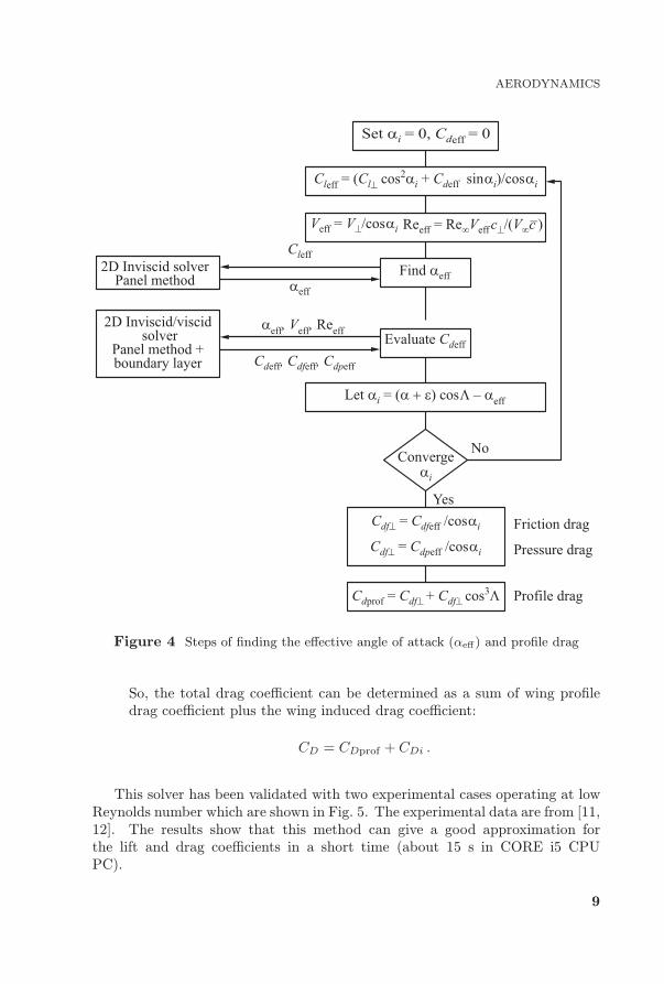
Figure 4 Steps of ¦nding the e¨ective angle of attack (αe¨) and pro¦le drag
So, the total drag coe©cient can be determined as a sum of wing pro¦le
drag coe©cient plus the wing induced drag coe©cient:
CD = CDprof + CDi .
This solver has been validated with two experimental cases operating at low
Reynolds number which are shown in Fig. 5. The experimental data are from [11,
12]. The results show that this method can give a good approximation for
the lift and drag coe©cients in a short time (about 15 s in CORE i5 CPU
PC).
9
Page 8
PROGRESS IN FLIGHT PHYSICS
Figure 5 Validation of quasi-3D solver (1) with two experimental cases (2),
Re = 3.1 · 106: (a) tapered wing validation (aspect ratio = 10, taper ratio = 1/3,
and Dihedral = 0.687◦); and (b) swept tapered wing validation (aspect ratio = 6, taper
ratio = 1/2, and Dihedral = 0.974◦)
4 STRUCTURE ANALYSIS
High altitude aircraft generally has an extreme span length, which suggests the
aircraft is very §exible; so, it is very important to employ the elastic in§u-
ence in the design tool. A MATLAB code has been written to size the wing
box and to predict its weight by using a quasi-analytical method for a given
aerodynamic load distribution (with other internal load such as weight and
other inboard components: propulsion system, fuel cell, solar cell, avionic sys-
tem, etc.) in addition to evaluating its deformation by using linear bending
and torsion theory. The wing box is modeled by means of a 3D ¦nite ele-
ment beam (thin-walled beam) concentrated on the elastic axis of the wing
such as shown in Fig. 6. This method is described in more detail in [11,
12]. The beam is discretized into elements, each element having two nodes.
10
Page 9
AERODYNAMICS
Figure 6 Sketch of the structural wing model and wing-box idealization
Each node has 6 degrees of freedom: three in translation and three in rota-
tion. They are described by a local coordinate and then described by their
rotation angles (sweep, dihedral, and twist) to transfer to the global coordi-
nate system. Tornado Vortex Lattice is used to evaluate the lift forces in each
element.
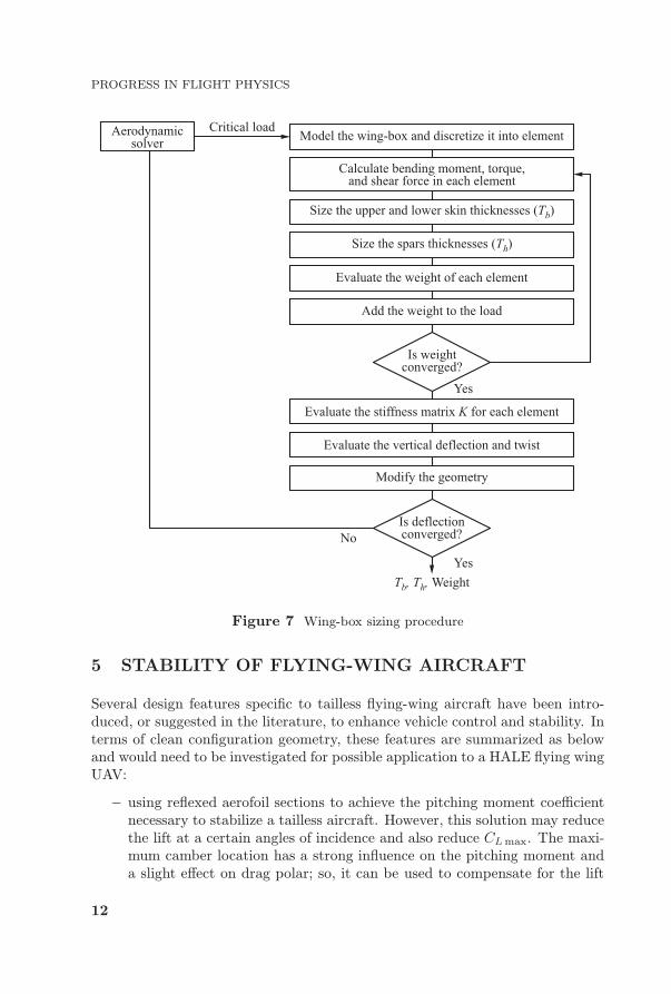
The tool starts with calculating the bending moment, shear force and torque
in each element. Then, it ¦nds the required thicknesses of the panel cross sec-
tion (Tb and Th, see Fig. 6), under a speci¦c load factor assuming that the
wing box resists all of the external force [11, 12]. The steps are shown in
Fig. 7. Once the element cross section is sized, then the weight will be eval-
uated. In addition, the ribs£ weight is evaluated from an empirical formula [12].
Element sizing includes spar web and equivalent skin representation, which is
produced by summing the upper and lower skin panels, stringers, and the spar
§ange (see Fig. 6). The equivalent upper and lower wing panels resist bend-
ing and torsional loadings. The spar webs resist the vertical shear and tor-
sional loads. The sizing process is iterated until the inertial relief e¨ect is
achieved.
The sti¨ness matrix K for each element is then determined using the geo-metric and mechanical properties of the elements. The node displacement U canbe evaluated by the following relation [13]:
F = KU
where F is the external load vectors; K is the sti¨ness matrix; and U is thedisplacement vector. After the sizing process, the de§ection calculation will be
performed which, in turn, requires the recalculation of the aerodynamic forces;
so, the sizing is then reiterated until a quasi-static equilibrium between the
structural and the aerodynamic forces is obtained.
11
Page 10
PROGRESS IN FLIGHT PHYSICS
Figure 7 Wing-box sizing procedure
5 STABILITY OF FLYING-WING AIRCRAFT
Several design features speci¦c to tailless §ying-wing aircraft have been intro-
duced, or suggested in the literature, to enhance vehicle control and stability. In
terms of clean con¦guration geometry, these features are summarized as below
and would need to be investigated for possible application to a HALE §ying wing
UAV:
using re§exed aerofoil sections to achieve the pitching moment coe©cient
necessary to stabilize a tailless aircraft. However, this solution may reduce
the lift at a certain angles of incidence and also reduce CLmax. The maxi-
mum camber location has a strong in§uence on the pitching moment and
a slight e¨ect on drag polar; so, it can be used to compensate for the lift
12
Page 11
AERODYNAMICS
reduction resulting from the use of a re§exed aerofoil section. The span-
wise twist distribution does not give enough help in terms of stability with
these types of aerofoil section [14, 15];
selecting a suitable combination of sweep and twist distribution to generate
zero pitching moment (with a slightly-re§exed aerofoil section) [16, 17];
using a suitable dihedral angle (or dihedral distribution) could add some
enhancement in the lateral direction [18]; and
using winglets or C-wings to reduce induced drag and add further direc-
tional stability and control [19, 20].
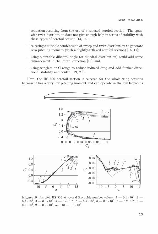
Here, the HS 520 aerofoil section is selected for the whole wing sections
because it has a very low pitching moment and can operate in the low Reynolds
Figure 8 Aerofoil HS 520 at several Reynolds number values: 1 ¡ 0.1 · 106; 2 ¡
0.2 · 106; 3 ¡ 0.3 · 106; 4 ¡ 0.4 · 106; 5 ¡ 0.5 · 106; 6 ¡ 0.6 · 106; 7 ¡ 0.7 · 106; 8 ¡
0.8 · 106; 9 ¡ 0.9 · 106; and 10 ¡ 1.0 · 106
13
Page 12
PROGRESS IN FLIGHT PHYSICS
number environment with a good maximum lift coe©cient as shown in Fig. 8,
which is given by XFLR v6 (similar to Xfoil 2D CFD).
6 PRECONCEPTUAL DESIGN
A solar powered HALE UAV uses only the solar irradiance which is, in turn,
dependent on the hour of the day, the day of the year, the latitude, and the
position of the solar cell panels. For long endurance mission, the aircraft can §y
continually if the energy collected during the daytime is enough to operate the
aircraft during the whole day [21]. The energy and mass balance should be the
starting point of the design. Motors, solar cell panels, fuel cells or batteries, and
avionic system are dimensioned according to the required power but at the same
time, they have weight which a¨ects the gross weight that, in turn, a¨ects the
required power. There are two di¨erent approaches to achieve the conceptual
design:
I The discrete and iterative approach: this is based on pure estima-
tion for the ¦rst set of components (motors, solar cell panels, fuel cell or
batteries, and avionic system) and from their weight, the total weight and
power required can be estimated. This power is then compared with the
previous selection and this process is performed iteratively until a converg-
ing solution is found. This approach requires more computational e¨ort
with good estimation models [22].
II An analytical and continuous approach: this consists of establishing
all the relationships between all the components with analytical functions
using their characteristics. This approach can provide directly a unique
and optimal design but requires a robust mathematical model [22]. Noth et
al. presented the methodology of designing a small solar powered aircraft,
which was used to design the ¦rst prototype of Sky-Sailor [23]. In this
paper, the second approach will be adopted with some modi¦cations to
the Noth methodology, particularly, in the structure mass and avionic
mass and power modeling. Rizzo and Frediani proposed a structure mass
estimation model which was obtained by data published for the NASA
prototypes [24]. This function can be written in term of span length and
aspect ratio to be implemented in the design tool:
maf = 1.548b1.312AR−0.0046 [kg] .
The mass and power of the system components can be estimated as a constant
fraction of the structural mass, or the total mass, or of the power as shown in
Fig. 9. Fuel cells with a lower mass to power density ratio are used instead of
batteries [1, 24].
14
Page 13
AERODYNAMICS
Figure 9 Schematic representation of the design methodology
The total mass m of the aircraft is the sum of all the components such as:
m = mpayload +maf +msc +mmppt +mavionic +mprop +mfc .
For simplicity, variables ai can be used instead of a heavy equation as shown in
Fig. 9 and after rearranging, the main equation becomes:
m = m
a12︷ ︸︸ ︷[(a5 + a6)a10a11a9 + a7a10a11 + a10]
+m3/2
b
a13︷ ︸︸ ︷[(a5 + a6)a0a1a9 + a7a0a1 + a8a0a1]
+ [bx1a4
a14︷ ︸︸ ︷+ a3 + (a5 + a6)a2a9 + a7a2]
15
Page 14
PROGRESS IN FLIGHT PHYSICS
where a1 a11 are de¦ned in Fig. 9. This will lead to:
m (1− a12)− m3/2
ba13 − (bx1a4 + a14) = 0 .
The positive real root of the latter equation can be found for di¨erent span
lengths (b) and aspect ratios (AR), but the solution should be constrained so
Table 1 The constant parameters of the design
Parameter Value Unit Description
CL 0.9 ¡ Aeroplane lift coe©cient
Cda 0.01 ¡ Aerofoil drag coe©cient
e 0.85 ¡ Oswald£s e©ciency factor
Imax 974 W/m2Maximum irradiance (minimum (Imax) between
March 1 and October 1) at latitude 31◦ south
of Iraq [25]
Kfc 550 × 3600 J/kg Energy density of fuel cell
Ksc 0.25 kg/m2 Mass density of solar cells
Kenc 0.01 kg/m2 Mass density of encapsulation
Kmppt 0.00047 kg/W Mass to power ratio of maximum power point tracker
Kprop 0.0045 kg/W Mass to power ratio of propulsion unit
Kaf 1.548 kg/m3 Structural mass constant
ηcbr 1∗ ¡ E©ciency of the curved solar panels
ηbec 1∗ ¡ E©ciency of step-down converter
ηsc 0.31 ¡E©ciency of solar cells (Triple-Junction
Epitaxial Lifto¨ Tabbed Solar Cell (MicroLink))
ηchrg 1∗ ¡ E©ciency of fuel cell charge
ηctrl 0.95 ¡ E©ciency of motor controller
ηdchrg 0.6 ¡ E©ciency of fuel cell discharge
ηgrb 1∗ ¡ E©ciency of gearbox
ηmot 0.95 ¡ E©ciency of motor
ηmppt 1∗ ¡ E©ciency of maximum power point tracker
ηplr 0.85 ¡ E©ciency of propeller
x1 1.312 ¡ Structural mass area exponent
x2 −0.0046 ¡ Structural mass aspect ratio exponent
Kav 0.03 ¡ Avionic weight fraction
Kpav 6 W/kg Power-to-mass ratio of avionics
ksolmargin 1∗ ¡ Irradiance margin factor
mpayload 50 kg Payload mass
Ppayload 850 W Payload power consumption
ρ 0.1382 kg/m3 Air density (at 17 km)
Tday 12 × 3600 s Daytime duration∗Ignored in the design.
16
Page 15
AERODYNAMICS
Figure 10 Possible design for the given mission requirements (MPPT ¡ maximum
power point tracker): 1 ¡ AR = 12; 2 ¡ 16; 3 ¡ 20; 4 ¡ 24; 5 ¡ 28; 6 ¡ 32; and
7 ¡ AR = 36
17
Page 16
PROGRESS IN FLIGHT PHYSICS
Table 2 The main aeroplane characteristics
Parameter Value Unit Description
AR 24 ¡ Aspect ratio
b 56 m Wingspan
m 731 kg Total mass
mavionic 22 kg Avionic weight
mfc 277 kg Fuel cell weight
mprop 31.5 kg Propulsion system weight
maf 300 kg Structure mass
msc 29.3 kg Mass of solar cells
mmppt 15 kg Mass of maximum power point tracker
S 130.7 m2 Platform area
cav 2.334 m Mean chord
V∞ 29.7 m/s Airspeed
that the value of the solar cell area is not more than the planform area. Ta-
ble 1 shows the constant parameters of the components with the other mission
requirements which are assumed still constant during the design process [23].
Applying this methodology to the design led to the possible shape of the
aeroplane, for given mission requirements, as illustrated in Fig. 10.
It is clear that the span corresponding to the minimum aeroplane weight is
about 56 m and aspect ratio 24. The ¦nal choice guides the §ight speed, struc-
ture weight, wing area, power and mass of fuel cells, avionic system, solar cells,
avionic system, and propulsion system as shown in Table 2. The initial geome-
try is now determined and need to be optimized to achieve the optimal §yable
geometry.
7 OPTIMIZATION
A design optimization framework has been developed, under a MATLAB envi-
ronment combining aerodynamic, structural, and stability analysis. A Canonical
Genetic Algorithm has been used in the optimization process to vary the geo-
metric variables until achieving the optimal design which is represented by the
maximum or minimum ¦tness target. The optimizer code has been developed
based on principle of genetic evolutionary processes as detailed in [26, 27]. Here,
a single objective optimization process is used to ¦nd the minimum drag for
a speci¦c lift coe©cient (CLreference = 0.9) and static margin (not less than 0.05).The ¦nal con¦guration should be stable statically and trimmed at the reference
lift coe©cient and at the mission altitude. Six electric motors are used and
18
Page 17
AERODYNAMICS
Figure 11 Optimization architecture
distributed along the span in addition to storage tanks of the fuel cells. The
other fuel cell components and payload are assumed to be located at root chord
and can be placed to adjust the center of gravity to achieve a speci¦c lift coef-
¦cient. The communication shape among the disciplinary tools is presented in
Fig. 11. A suitable mesh density is used to achieve a good sensitivity with vary-
ing the geometric variables for this con¦guration (5 chordwise × 39 semispan-wise panels are used for each half span or 390 panels for entire wing). Increasing
the number of panels can lead to more accuracy, but at more computational
cost.
The problem here is formulated for a constant area and wing span to vary
the root chord, the sweep of each part of the wing (Sw1 and Sw2), their taper
ratio (TR1 and TR2), length of the ¦rst partition (b1), and the twist distribu-tion of the wing (Fig. 12). A static longitudinal stability only is considered now.
19
Page 18
PROGRESS IN FLIGHT PHYSICS
Figure 12 Design variable of the half wing
Further implementation such as lateral and directional static and dynamic sta-
bility will be implemented in the future work. This problem is formulated as
follows:
Minimize: CD
Variables: TR1, TR2, Sw1, Sw2, Cr, b1, twist distribution
Subject to CL ≥ CLreference, Cm = 0, no separation is allowed, S = 130.7 m2,
span = 56 m
8 OPTIMIZATION RESULTS
The results, which are obtained from the optimization, show that it can achieve
a §yable §ying wing for the given mission and §ight state. The aeroplane is
trimmed at 11.7 degree angle of attack, 0.905 lift coe©cient, and 0.0193 to-
tal drag coe©cient. The gradient of the pitching moment coe©cient is −0.053and the zero lift pitching moment coe©cient is approximately 0.0536, indicating
a statically stable aeroplane in the longitudinal mode. The ¦nal con¦guration is
shown in Fig. 13.
The sweep required to trim this aeroplane is about 8◦ with the washout twist
distribution shown in Fig. 14. Only the root section seems close to stall angle at
cruise condition (see Fig. 8) while the washout twist distribution (see Fig. 14)
can prevent stalling for the rest of the wing. Even if the tool does not predict
any separation at any section at cruise condition, this would be investigated by
a high-order CFD or by an experiment for further reliability in the future work.
It is known that the structure de§ection has an e¨ect on the aeroplane geometry
20
Page 19
AERODYNAMICS
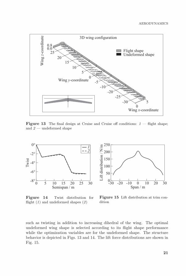
Figure 13 The ¦nal design at Cruise and Cruise o¨ conditions: 1 ¡ §ight shape;
and 2 ¡ undeformed shape
Figure 14 Twist distribution for
§ight (1) and undeformed shapes (2)
Figure 15 Lift distribution at trim con-
dition
such as twisting in addition to increasing dihedral of the wing. The optimal
undeformed wing shape is selected according to its §ight shape performance
while the optimization variables are for the undeformed shape. The structure
behavior is depicted in Figs. 13 and 14. The lift force distributions are shown in
Fig. 15.
21
Page 20
PROGRESS IN FLIGHT PHYSICS
9 CONCLUDING REMARKS
This paper presents a design and optimization framework employing aerodynam-
ics and structure in§uence for a HALE, solar-powered §ying wing UAV. By using
modi¦ed low-order analysis tools that are employed to facilitate e©cient compu-
tations for the various engineering analyses, a good approximation is achieved
compared to the experimental data. Applying the §ying-wing con¦guration in
this tool leads to an aeroplane that can be trimmed to carry the designed pay-
load for long endurance (6 months) at latitude 31 N and altitude 17 km. As
expected, the static longitudinal stability requires the design to be swept and
twisted to give a moment arm behind the neutral axis to trim the aeroplane at
the reference lift coe©cient.
Future work to be undertaken includes analyzing the dynamic stability and
control, using nonlinear structure behavior, using composite materials instead
of a metallic wing structure, comparison between di¨erent con¦gurations, and
using multiobjective optimization to cover several objective targets.
ACKNOWLEDGMENTS
The authors would like to thank and dedicate this to Dr. L. J. Johnston who
passed away during work on the present paper.
REFERENCES
1. Cestino, E., G. Frulla, and G. Romeo. 2007. Design of a high-altitude long-
endurance solar-powered unmanned air vehicle for multi-payload and operations.
P. I. Mech. Eng. G J. Aer. Eng. 221(2):199 216.
2. Zdobys¬law, G., F. Andrzej, and W. Jacek. 1999. Design concept of a high-altitude
long-endurance unmanned aerial vehicle. Aircraft Design 2(1):19 44.
3. Rapinett, A. 2009. Zephyr a high altitude long endurance unmanned air vehicle.
Department of Physics, University of Surrey. MSc Thesis.
4. Cestino, E. 2006. Design of solar high altitude long endurance aircraft for multi
payload & operations. Aerosp. Sci. Technol. 10(6):541 550.
5. Wauquiez, C. 2009. Shape optimization of low speed airfoils using MATLAB and
automatic di¨erentiation. VDM Verlag. 68 p.
6. Moran, J. 1984. An introduction to theoretical and computational aerodynamics.
Mineola, NY: Dover Publications, Inc. 466 p.
7. Katz, J., and A. Plotkin. 2001. Low-speed aerodynamics. Cambridge aerospace ser.
Cambridge University Press. Vol. 13. 613 p.
22
Page 21
AERODYNAMICS
8. Mariens, J. 2012. Wing Shape multidisciplinary design optimization. Aerospace
Engineering, Delft University of Technology. MSc Thesis.
9. Mariens, J., A. Elham, and M. van Tooren. 2014. Quasi-three-dimensional aerody-
namic solver for multidisciplinary design optimization of lifting surfaces. J. Aircraft
51(2):547 558.
10. Obert, E. 2009. Aerodynamic design of transport aircraft. IOS PRESS. 656 p.
11. Ajaj, R. M., D. Smith, and A. T. Isikveren. 2013. A conceptual wing-box weight
estimation model for transport aircraft. Aeronaut. J. 177(1191):533 551.
12. Torenbeek, E. 2013. Advanced aircraft design: Conceptual design, technology and
optimization of subsonic civil airplanes. John Wiley & Sons. 436 p.
13. Seywald, K. 2011. Wingbox mass prediction considering quasi-static nonlinear
aeroelasticity. Technische Universit�at and Kungliga Tekniska h�ogskolan. Bauhaus
Luftfahrt. Diploma Thesis.
14. Buckstrom, A. 1979. The elements of tailless airplane design. Sport Aviation 39
44.
15. Qin, N., A. Vavalle, A. Le Moigne, et al. 2004. Aerodynamic considerations of
blended wing body aircraft. Prog. Aerosp. Sci. 40(6):321 343.
16. Li, P., B. Zhang, Y. Chen, et al. 2012. Aerodynamic design methodology for blended
wing body transport. Chinese J. Aeronaut. 25(4):508 516.
17. Mader, C. A., and J. R. Martins. 2013. Stability-constrained aerodynamic shape
optimization of §ying wings. J. Aircraft 50(5):1431 1449.
18. Song, L., H. Jang, Y. Zhang, et al. 2014. Dihedral in§uence on lateral directional
dynamic stability on large aspect ratio tailless §ying wing aircraft. Chinese J. Aero-
naut. 27(5):1149 1155.
19. Bolsunovsky, A., N. Buzoverya, B. Gurevich, et al. 2001. Flying wing ¡ problems
and decisions. Aircraft Design 4(4):193 219.
20. Martinez-Val, R., E. Perez, P. Alfaro, and J. Perez. 2007. Conceptual design of
a medium size §ying wing. P. I. Mech. Eng. G J. Aer. Eng. 221(1):57 66.
21. Gao, X.-Z., Z. Hou, Z. Guo, J Liu, and X.-Q. Chen. 2013. Energy management
strategy for solar-powered high-altitude long-endurance aircraft. Energ. Convers.
Manage. 70:20 30.
22. Noth, A. 2008. Design of solar powered airplanes for continuous §ight. ETH Z�urich.
PhD Thesis.
23. Noth, A., R. Siegwart, and W. Engel. 2008. Design of solar powered airplanes for
continuous §ight. 19 p.
24. Rizzo, E., and A. Frediani. 2008. A model for solar powered aircraft preliminary
design. Aeronaut. J. 112(1128):57 78.
25. Tadros, M. T. Y., M. A. M. Mustafa, and M. Abdel-Wahab. 2014. Estimation of
the global horizontal solar radiation in Iraq. Int. J. Emerging Technol. Adv. Eng.
4(8).
23
Page 22
PROGRESS IN FLIGHT PHYSICS
26. Khan, F. A., P. Krammer, and D. Scholz. 2010. Preliminary aerodynamic investi-
gation of box-wing con¦gurations using low ¦delity codes. DGLR Dtsch. Luft-und.
Document ID: 161308.
27. Khan, F. A. 2010. Prelimnary aerodynamic investigation of box-wing con¦grations
using low ¦delity code. Department of Space Science, Luleƒa University of Technol-
ogy. MSc Thesis.
24