Engineering Structures 29 (2007) 1074–1083 www.elsevier.com/locate/engstruct Design of FRP confinement for square concrete columns Shamim A. Sheikh a,* , Yimin Li b a Department of Civil Engineering at the University of Toronto, Toronto, Ontario, Canada b Hatch Acres Incorporated, Oakville, Ontario, Canada Received 4 August 2005; received in revised form 20 February 2006; accepted 18 July 2006 Available online 26 September 2006 Abstract A procedure for the design of confining fibre-reinforced polymer (FRP) reinforcement in square concrete columns to enhance their seismic resistance is presented. In previous research, a method was developed for the design of confining steel in square reinforced concrete columns [Sheikh SA, Khoury SS. A performance-based approach for the design of confining steel in tied columns. ACI Struct J 1997;94(4):421–31]. Patterned on the same philosophy, the procedure presented here allows a designer to calculate the amount of confining FRP required for a certain ductility performance given the axial load on the column and the properties of the FRP. The required FRP content increases with an increase in ductility demand and an increase in the level of axial load applied. The procedure can be applied to new and existing square concrete columns and is corroborated with the experimental results obtained from realistically sized columns tested under simulated earthquake loads. c 2006 Elsevier Ltd. All rights reserved. Keywords: Columns; Confinement; Ductility; Earthquake; Energy dissipation; Retrofitting 1. Introduction Many of the existing reinforced concrete structures built according to pre-1970 design codes may not have sufficient ability to resist severe earthquakes. A major deficiency of these structures has been the inadequate amount of confinement reinforcement in potential plastic hinge regions of the columns that results in brittle structural response during earthquakes. To provide additional confinement to these deficient columns, retrofitting with fibre-reinforced polymer (FRP) jackets provides a very attractive solution due to their lightweight, high strength and excellent corrosion resisting capabilities. The current design code provisions [2,3] require large amounts of steel reinforcement placed at small spacing in critical regions of columns, which, quite often, makes construction very cumbersome and at times impractical. Use of external FRP shells with fibres aligned in the circumferential direction of the column can provide confinement and act as formwork for new structures. Many experimental studies [4–12] have confirmed that the confinement provided by the FRP wraps can significantly * Corresponding author. Tel.: +1 416 978 3671; fax: +1 416 978 7046. E-mail address: [email protected](S.A. Sheikh). increase the energy absorption capacity and ductility of the columns under combined axial, flexural and shear loads, thereby increasing their seismic resistance. This technique is gaining popularity in the field and a rational yet easy to use method is needed for the design of confining FRP so that practicing engineers can implement this new technology with confidence. It is generally agreed that circular confinement, due to its intrinsic nature, is considerably more efficient than square confinement. This paper is focused on square columns partly because of the availability of extensive data from well- instrumented square columns tested in a similar manner under simulated earthquake loads. Experimental and analytical work on circular columns is in progress on similar lines. Preliminary results indicate that the amount of FRP reinforcement required in circular columns is about half of what is required in square columns for similar improvement in ductility. 2. Proposed design approach In order to develop a procedure for the design of confining FRP for square concrete columns, an extensive review of the available test results was conducted. Table 1 lists some of the available results from the tests on square or rectangular FRP- confined concrete columns under constant axial load and cyclic 0141-0296/$ - see front matter c 2006 Elsevier Ltd. All rights reserved. doi:10.1016/j.engstruct.2006.07.016
Keywords: Columns; Confinement; Ductility; Earthquake; Energy dissipation; Retrofitting
1. Introduction
Many of the existing reinforced concrete structures builtaccording to pre-1970 design codes may not have sufficientability to resist severe earthquakes. A major deficiencyof these structures has been the inadequate amount ofconfinement reinforcement in potential plastic hinge regionsof the columns that results in brittle structural responseduring earthquakes. To provide additional confinement to thesedeficient columns, retrofitting with fibre-reinforced polymer(FRP) jackets provides a very attractive solution due to theirlightweight, high strength and excellent corrosion resistingcapabilities. The current design code provisions [2,3] requirelarge amounts of steel reinforcement placed at small spacingin critical regions of columns, which, quite often, makesconstruction very cumbersome and at times impractical. Use ofexternal FRP shells with fibres aligned in the circumferentialdirection of the column can provide confinement and act asformwork for new structures.
Many experimental studies [4–12] have confirmed that theconfinement provided by the FRP wraps can significantly
increase the energy absorption capacity and ductility of thecolumns under combined axial, flexural and shear loads,thereby increasing their seismic resistance. This technique isgaining popularity in the field and a rational yet easy to usemethod is needed for the design of confining FRP so thatpracticing engineers can implement this new technology withconfidence. It is generally agreed that circular confinement,due to its intrinsic nature, is considerably more efficient thansquare confinement. This paper is focused on square columnspartly because of the availability of extensive data from well-instrumented square columns tested in a similar manner undersimulated earthquake loads. Experimental and analytical workon circular columns is in progress on similar lines. Preliminaryresults indicate that the amount of FRP reinforcement requiredin circular columns is about half of what is required in squarecolumns for similar improvement in ductility.
2. Proposed design approach
In order to develop a procedure for the design of confiningFRP for square concrete columns, an extensive review of theavailable test results was conducted. Table 1 lists some of theavailable results from the tests on square or rectangular FRP-confined concrete columns under constant axial load and cyclic
ctangular or square columns tested under cyclic lateral loads and constant axial loads
Size and shape of specimens Concretestrength (MPa)
Longitudinal steel Lateral steel
fy(MPa)
ρt (%) fy(MPa)
s(m
241 mm × 368 mm 1.892 mtall with one end stub
34.9 and 33.4 359 2.70a
and 5.45301 11
410 mm square, 2.34 m tallwith two end stubs
29 462 3a 455 30
305 mm square, 1.47 m tallwith one end stub
36.5–42.3 465 2.58 457 30
305 mm square, 1.47 m tallwith one end stub
42.5–44.2 465 2.58 457 30
305 mm square, 1.47 m tallwith one end stub
26.8–27.2 465 2.58a 492 30
305 mm square, 1.47 m tallwith one end stub
28.5 465 2.58a 509 30
270 mm square, 1.72 m tallwith one end stub
90 475 and500
1.68 and3.36
One columncrossties @ 6
260 mm square, 1.65 m tallwith one end stub
53 and 52 420 1.5 and 3 420 12
ces in test regions.
1076 S.A. Sheikh, Y. Li / Engineering Structures 29 (2007) 1074–1083
Fig. 1. Schematic test setup.
lateral load. This review indicated that the results availableare limited. Although there exists a consensus that confiningFRP can significantly enhance the seismic performance andductility of square or rectangular concrete columns, the testsetups, loading histories, instrumentations, specimen detailsand ductility parameters used in the available experimentalinvestigations were different from one programme to another,making it difficult to evaluate these results on a commonplatform. Among these results, the columns tested by Iacobucciet al. [4] and Memon and Sheikh [5] were tested under similarconditions. More importantly, in these tests the specimenswere similar and the moment–curvature behaviour of the mostdamaged regions of the specimens was reported, which isessential for the calculation of the ductility parameters used inthe proposed design procedure. For these reasons, only theseexperimental results were used to corroborate the proposeddesign procedure. Also, since the procedure was developed forcolumns with continuous longitudinal rebar in plastic hingeregions, test data of columns with lap spliced longitudinal barsin plastic hinge regions were not considered when developingthe procedure.
The proposed design approach was developed on thepattern of the procedure for the design of steel confiningreinforcement [1]. The parameters used for evaluating theductile performance of a column include section and memberductility, energy dissipation capacity and the number ofstandard displacement excursions a column could sustainbefore failure. Detailed development of this design procedureis available elsewhere [1,13]. However, some background dataand the derivation of the procedure are briefly explained here.
2.1. Experimental results and ductility parameters
The proposed approach was developed using the experimen-tal results of ten realistically sized FRP-confined specimens re-ported by Iacobucci et al. [4] and Memon and Sheikh [5]. In
these experimental programmes, reinforced concrete columnswith 305 mm square sections were tested under cyclic shear andflexure while simultaneously subjected to constant axial loadto simulate earthquake loads, as shown in Fig. 1. The lateraldisplacement excursion regime consisted of one cycle to a dis-placement of 0.75∆1 followed by 2 cycles each of ∆1, 2∆1,3∆1 and so on until the specimen was unable to sustain theapplied axial load. Analytical yield displacement ∆1 was thelateral deflection corresponding to the estimated maximum lat-eral load along a load–deflection line that represented the initialstiffness of the column. Each specimen consisted of a 1.47 mlong column cast integrally with a 510 × 760 × 810 mm stubthat represented a beam–column joint or a footing. The columnswere internally reinforced with steel and externally confined bydifferent amounts of continuous CFRP or GFRP wraps. Theultimate tensile strength and rupture strain of the CFRP fabricwere 962 N/mm width per layer and 0.0126, respectively, whilethese values for the GFRP fabric were 563 N/mm width perlayer and 0.0228, respectively. In addition, three steel-confinedcolumns without FRP wraps, i.e. AS-1NS, AS-8NS, and AS-1NSS, were tested as control specimens. Table 2 lists the detailsof the specimens considered in this study.
In evaluating the seismic performance of the columnsand studying the effects of different variables, ductility andtoughness parameters defined in Fig. 2 were used [1]. Theseinclude curvature ductility factor µφ , cumulative ductility ratioNφ , and energy-damage indicator E . Subscripts t and 80indicate, respectively, the value of the parameter until the endof the test (total value) and the value until the end of the cycle inwhich the moment has dropped to 80% of the maximum value.The energy parameter ei represents the area enclosed in cyclei by the M–φ loop. Terms L f and h represent the length ofthe most damaged region measured from the test and the depthof the column section, respectively. All other terms are definedin Fig. 2. The energy-damage indicator E is similar to the oneproposed by Ehsani and Wight [14] for force–deflection curves.
S.A. Sheikh, Y. Li / Engineering Structures 29 (2007) 1074–1083 1077
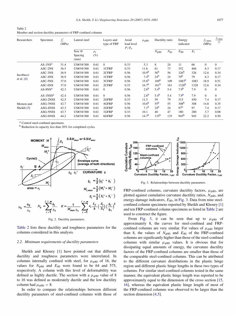
Table 2Member and section ductility parameters of FRP-confined columns
a Control steel-confined specimens.b Reduction in capacity less than 20% for completed cycles.
Fig. 2. Ductility parameters.
Table 2 lists these ductility and toughness parameters for thecolumns considered in this analysis.
2.2. Minimum requirements of ductility parameters
Sheikh and Khoury [1] have pointed out that differentductility and toughness parameters were interrelated. Incolumns internally confined with steel, for µφ80 of 16, thevalues for Nφ80 and E80 were found to be 64 and 575,respectively. A column with this level of deformability wasdefined as highly ductile. The section with a µφ80 value of 8to 16 was defined as moderately ductile and the low ductilitycolumn had µφ80 < 8.
In order to compare the relationships between differentductility parameters of steel-confined columns with those of
Fig. 3. Relationships between ductility parameters.
FRP-confined columns, curvature ductility factors, µφ80, areplotted against cumulative curvature ductility ratios, Nφ80, andenergy-damage indicators, E80, in Fig. 3. Data from nine steel-confined column specimens reported by Sheikh and Khoury [1]and ten FRP-confined column specimens as listed in Table 2 areused to construct the figure.
From Fig. 3, it can be seen that up to µφ80 ofapproximately 8, the curves for steel-confined and FRP-confined columns are very similar. For values of µφ80 largerthan 8, the values of Nφ80 and E80 of the FRP-confinedcolumns are significantly higher than those of the steel-confinedcolumns with similar µφ80 values. It is obvious that fordissipating equal amounts of energy, the curvature ductilityfactors of the FRP-confined columns are smaller than those ofthe comparable steel-confined columns. This can be attributedto the different curvature distributions in the plastic hingeregion and different plastic hinge lengths in these two types ofcolumns. For similar steel-confined columns tested in the samemanner, the equivalent plastic hinge length was reported to beapproximately equal to the dimension of the cross section [15,16], whereas the equivalent plastic hinge length of most ofthe FRP-confined columns was observed to be larger than thesection dimension [4,5].
1078 S.A. Sheikh, Y. Li / Engineering Structures 29 (2007) 1074–1083
For steel-confined columns, a µφ80 value of 16 correspondsto E80 = 575, while a µφ80 value of 8 corresponds to E80 =
123. From the curves for FRP-confined columns in Fig. 3, it canbe seen that at E80 = 575, the corresponding value for µφ80 is13.2; while at E80 = 123, the corresponding value for µφ80 is8.2. Considering the energy dissipation capacity, the behaviourof a FRP-confined column with µφ80 = 13 can be considered ashighly ductile. The section with a µφ80 value of 8 to 13 can thusbe defined as moderately ductile and the low ductility columnhas µφ80 < 8.
2.3. Design procedure
Sheikh and Khoury [1] proposed a procedure for the designof confining steel for square steel-confined columns. The designequations were as follows:
Ash = α · 0.3shc
(Ag
Ach− 1
)f ′c
fy· YP · Yφ
≥ α · 0.09shcf ′c
fy· YP · Yφ (1)
where Ash is the total cross sectional area of rectilinear steelperpendicular to dimension hc; α is confinement efficiencyparameter related to steel configuration; s is tie spacing; hcis the dimension of concrete core measured to the outside ofperimeter tie; Ag is gross area of section; Ach is area of theconcrete core measured to the outside of perimeter tie; f ′
c iscompressive strength of concrete; fy is yield strength of lateralsteel; YP is a parameter to take into account the effect of axialload and taken as:
YP = 1 + 13 ·
(PPo
)5
(2)
and Yφ is a parameter to take into account the section ductilitydemand and taken as:
Yφ =µ1.15
φ80
29.0. (3)
Sheikh and Khoury [1] also suggested the following simplifiedlinear expressions for YP and Yφ :
YP = 6PPo
− 1.4 ≥ 1 (4)
Yφ =µφ80
18. (5)
Eq. (1) can be rearranged as
fl
f ′c
= α · 0.3(
Ag
Ach− 1
)· YP · Yφ ≥ α · 0.09 · YP · Yφ (6)
where fl is the lateral confining pressure exerted by the lateralsteel to the concrete core and can be calculated as
fl =Ash · fy
s · hc. (7)
From Eq. (6), it can be observed that the required lateralconfining pressure normalized with respect to the concrete
strength f ′c , which can be defined as the confinement ratio [17],
increases with an increase in axial load level or an increase inductility demand. The required confinement ratio also dependson the confinement efficiency of the lateral reinforcement.The higher the confinement efficiency of the lateral steel,the lower the required confinement ratio. The design methodwhen applied to realistically sized specimens tested by differentinvestigators yielded excellent agreement with the experimentalresults.
2.4. Design considerations for square FRP-confined columns
Based on the experimental results listed in Table 2, the mostimportant variables identified to affect a column’s ductility arethe amount of FRP confining reinforcement, type of FRP andthe level of axial load. The effect of these variables on columnbehaviour is discussed in the following.
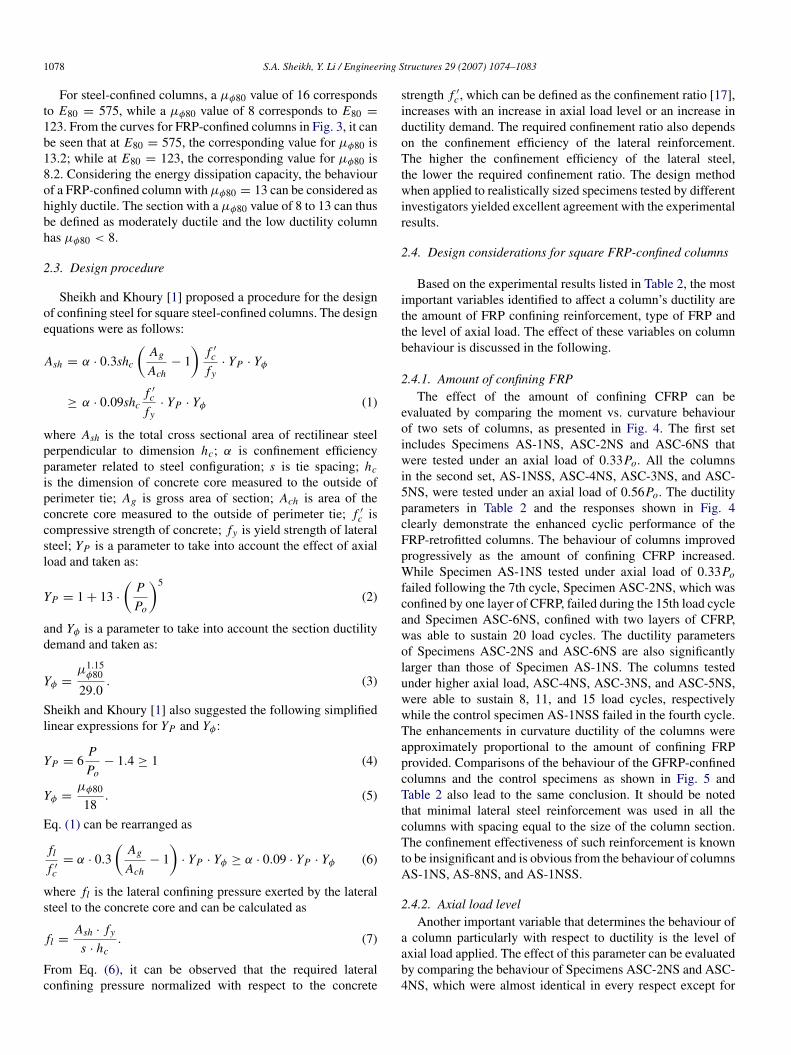
2.4.1. Amount of confining FRPThe effect of the amount of confining CFRP can be
evaluated by comparing the moment vs. curvature behaviourof two sets of columns, as presented in Fig. 4. The first setincludes Specimens AS-1NS, ASC-2NS and ASC-6NS thatwere tested under an axial load of 0.33Po. All the columnsin the second set, AS-1NSS, ASC-4NS, ASC-3NS, and ASC-5NS, were tested under an axial load of 0.56Po. The ductilityparameters in Table 2 and the responses shown in Fig. 4clearly demonstrate the enhanced cyclic performance of theFRP-retrofitted columns. The behaviour of columns improvedprogressively as the amount of confining CFRP increased.While Specimen AS-1NS tested under axial load of 0.33Pofailed following the 7th cycle, Specimen ASC-2NS, which wasconfined by one layer of CFRP, failed during the 15th load cycleand Specimen ASC-6NS, confined with two layers of CFRP,was able to sustain 20 load cycles. The ductility parametersof Specimens ASC-2NS and ASC-6NS are also significantlylarger than those of Specimen AS-1NS. The columns testedunder higher axial load, ASC-4NS, ASC-3NS, and ASC-5NS,were able to sustain 8, 11, and 15 load cycles, respectivelywhile the control specimen AS-1NSS failed in the fourth cycle.The enhancements in curvature ductility of the columns wereapproximately proportional to the amount of confining FRPprovided. Comparisons of the behaviour of the GFRP-confinedcolumns and the control specimens as shown in Fig. 5 andTable 2 also lead to the same conclusion. It should be notedthat minimal lateral steel reinforcement was used in all thecolumns with spacing equal to the size of the column section.The confinement effectiveness of such reinforcement is knownto be insignificant and is obvious from the behaviour of columnsAS-1NS, AS-8NS, and AS-1NSS.
2.4.2. Axial load levelAnother important variable that determines the behaviour of
a column particularly with respect to ductility is the level ofaxial load applied. The effect of this parameter can be evaluatedby comparing the behaviour of Specimens ASC-2NS and ASC-4NS, which were almost identical in every respect except for
S.A. Sheikh, Y. Li / Engineering Structures 29 (2007) 1074–1083 1079
(a) Specimens tested under an axial load of 0.33Po. (b) Specimens tested under an axial load of 0.56Po.
Fig. 4. Behaviour of CFRP-confined specimens.
the different levels of axial load applied. An increase in axialload from 0.33Po in ASC-2NS to 0.56Po in ASC-4NS resultedin significantly less ductile behaviour. The column resistinga high axial load experienced a decline in ductility ratio ofapproximately 60% and dissipated energy of about 75%. Itsexcursion limit was also reduced to 8 cycles from 15 for thespecimen under lower axial load. Similar observations can bemade by comparing the behaviour of Specimens ASC-6NS andASC-3NS in Fig. 4. Specimens ASG-2NSS and ASG-4NSSconfined with two layers of GFRP can also be compared toevaluate the effect of axial load (Fig. 5). Increase in axial load
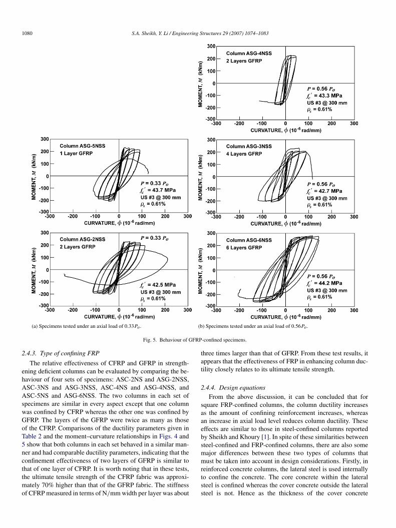
from 0.33Po to 0.56Po reduced the ductility factor from 11.5 to7.1. The energy dissipation for ASG-2NSS tested under loweraxial load is approximately 4.7 times larger than the energydissipated by specimen ASG-4NSS. Inclusion of specimenASG-3NSS in the comparison shows that the effects of thehigher axial load can be countered by an increase in the lateralFRP confinement. Specimen ASG-3NSS was strengthened with4 layers of GFRP and tested at high axial load of 0.56Po.Moment–curvature responses of ASG-2NSS and ASG-3NSSare very similar with ASG-2NSS displaying a little more ductilebehaviour.
1080 S.A. Sheikh, Y. Li / Engineering Structures 29 (2007) 1074–1083
(a) Specimens tested under an axial load of 0.33Po. (b) Specimens tested under an axial load of 0.56Po.
Fig. 5. Behaviour of GFRP-confined specimens.
2.4.3. Type of confining FRP
The relative effectiveness of CFRP and GFRP in strength-ening deficient columns can be evaluated by comparing the be-haviour of four sets of specimens: ASC-2NS and ASG-2NSS,ASC-3NS and ASG-3NSS, ASC-4NS and ASG-4NSS, andASC-5NS and ASG-6NSS. The two columns in each set ofspecimens are similar in every aspect except that one columnwas confined by CFRP whereas the other one was confined byGFRP. The layers of the GFRP were twice as many as thoseof the CFRP. Comparisons of the ductility parameters given inTable 2 and the moment–curvature relationships in Figs. 4 and5 show that both columns in each set behaved in a similar man-ner and had comparable ductility parameters, indicating that theconfinement effectiveness of two layers of GFRP is similar tothat of one layer of CFRP. It is worth noting that in these tests,the ultimate tensile strength of the CFRP fabric was approxi-mately 70% higher than that of the GFRP fabric. The stiffnessof CFRP measured in terms of N/mm width per layer was about
three times larger than that of GFRP. From these test results, itappears that the effectiveness of FRP in enhancing column duc-tility closely relates to its ultimate tensile strength.
2.4.4. Design equationsFrom the above discussion, it can be concluded that for
square FRP-confined columns, the column ductility increasesas the amount of confining reinforcement increases, whereasan increase in axial load level reduces column ductility. Theseeffects are similar to those in steel-confined columns reportedby Sheikh and Khoury [1]. In spite of these similarities betweensteel-confined and FRP-confined columns, there are also somemajor differences between these two types of columns thatmust be taken into account in design considerations. Firstly, inreinforced concrete columns, the lateral steel is used internallyto confine the concrete. The core concrete within the lateralsteel is confined whereas the cover concrete outside the lateralsteel is not. Hence as the thickness of the cover concrete
S.A. Sheikh, Y. Li / Engineering Structures 29 (2007) 1074–1083 1081
Fig. 6. Lateral confining pressure provided by FRP in square columns.
increases, the area of the confined concrete decreases. As aresult, more confinement reinforcement will be required toachieve a certain ductility performance. The Ag/Ach ratio inEq. (1) for steel-confined columns takes into account thiseffect. In FRP-confined columns, however, the FRP wraps areused externally thus confining the entire cross section of thecolumn. Therefore, the thickness of the cover concrete has noeffect on column behaviour and need not be considered as adesign parameter. Another important difference is the natureof the lateral confining pressure exerted by steel and FRP. Insteel-confined columns undergoing inelastic deformations, theconfining pressure remains practically constant while the steelyields under hoop tension. In columns continuously confinedby FRP, on the other hand, the lateral confining pressure isnot constant. As the concrete core expands laterally and thelateral strain increases, the confining pressure keeps increasingup to the rupture of fibres due to the linear elastic stress–straincharacteristic of the FRP.
For square columns confined by FRP as shown in Fig. 6,the lateral confining pressure provided by the FRP, fl , can becalculated as:
fl =2 · n · fFRP
h(8)
where n = number of layers of FRP; fFRP = tensile stress inFRP and h = cross sectional dimension of column.
It is not always possible to measure the actual averagestrains of the FRP at the location of failure in a column.Strains measured elsewhere in FRP would generally be lower,which may lead to an incorrect assumption that FRP fails ata lower strain in a column than in a coupon test. Jaffry andSheikh [18] have observed that tensile strains in FRP at failureof the columns under concentric compression were close to therupture strain of FRP under axial tension. Iacobucci et al. [4]have also made similar observations for columns tested undercombined loads. From the experimental results listed in Table 2,
Fig. 7. Relationship between curvature ductility factor, µφ80 and theoreticalmaximum lateral confining pressure provided by FRP, fl,max.
it was also found that there is a clear relationship between thecurvature ductility factors of the columns and the theoreticalmaximum lateral confining pressure, fl,max, provided by theFRP, which can be defined as:
fl,max =2 · n · fu
h(9)
where fu is the ultimate tensile strength of the FRP obtainedfrom tensile coupon tests. Other terms are as defined earlier.
The theoretical maximum lateral confining pressuresprovided by FRP, fl,max, were calculated for the ten specimensand are listed in Table 2. The relationship between the curvatureductility factor and theoretical maximum lateral confiningpressure provided by the FRP is shown in Fig. 7. In thisfigure, the theoretical maximum lateral confining pressuresare normalized with respect to the unconfined concretecompressive strength of the columns, which can be defined asthe confinement ratio for the columns [17].
Fig. 7 indicates that for a certain level of axial load, thecurvature ductility factor, µφ80, of a column increases almostlinearly with the increase in the confinement ratio, as shownby the two dashed lines in the figure. This relationship can beexpressed by the following equation:
fl,max
f ′c
= λ · Yp · Yφ (10)
where λ is a constant and YP and Yφ are parameters to takeinto account the effect of axial load and the section ductilitydemand. Substituting Eq. (9) into Eq. (10) and rearranginggives:
n · fu = β · f ′c · h · YP · Yφ (11)
where β is a confinement efficiency parameter and equal to λ/2.In the application of Eq. (11), along with Eqs. (2) and (3)
suggested by Sheikh and Khoury [1], to the aforementionedFRP-confined columns, it was found that the expressionsfor YP and Yφ for steel-confined concrete columns wereequally applicable to FRP-confined columns. Substituting theexpressions for YP and Yφ (Eqs. (2) and (3)) into Eq. (11) gives
1082 S.A. Sheikh, Y. Li / Engineering Structures 29 (2007) 1074–1083
Table 3Value of β
Specimen µφ80 Control specimen µφ80 of control specimen µφ80,in Value of β
where µφ80,in is the increase in curvature ductility factor due toFRP confinement and
µφ80,in = µφ80 − µφ80,con (13)
where:µφ80 = curvature ductility factor of the FRP-confinedspecimen; andµφ80,con = curvature ductility factor of the control reinforcedspecimen.The experimental results of the ten FRP-confined columns wereused to calculate the value for β using Eq. (12). The results arelisted in Table 3. The average value of β is about 0.25 and thestandard deviation is 0.03.
The simplified version of the above equation can be writtenas
n · fu = β · h · f ′c ·
(6
PPo
− 1.4)
µφ80,in
18
≥ β · h · f ′c ·
µφ80,in
18. (14)
The experimental curvature ductility factors and analyticalvalues obtained from Eqs. (12) and (14) are compared in Fig. 8.The average of the analytical curvature ductility factors usingEq. (12) is roughly equal to the average of the experimentalvalues and the standard deviation from the mean is about6%, whereas Eq. (14) is more conservative and slightlyunderestimates the curvature ductility of the columns in mostcases.
The above design procedure is applicable to square normalstrength concrete columns confined by continuous FRP wrapswith continuous longitudinal rebar in plastic hinge regions.Its applicability to high strength concrete columns andcolumns confined by non-continuous FRP bands needs furtherinvestigation. The design procedure was corroborated withthe test results on columns with 305 mm square sections, itsapplicability to columns with significantly different sizes is notconfirmed due to a lack of such data.
Fig. 8. Comparison of experimental and analytical curvature ductility factors.
3. Application of the proposed design approach
The proposed method is applied to a 450 mm square columnreinforced with eight longitudinal bars of 25 mm diameter.The concrete compressive strength and FRP rupture strengthare assumed to be 35 MPa and 900 N/mm width per layer,respectively. Yield strength of steel is taken as 400 MPa. Fig. 9shows the number of layers needed as a function of the columnaxial load for two values of ductility enhancement. If it isassumed that the original steel-reinforced column is capable ofdisplaying a ductility factor of 4, enhancements of µφ80 by 4and 9 would make the column moderately and highly ductile,respectively. Addition of one layer of FRP would make thecolumn moderately ductile if the axial load is 0.5P/Po. Forthe same level of axial load, 2.4 layers of FRP are neededto make the column highly ductile thus requiring three layersof FRP wrap in practice. If three layers are used, the FRPstrength can be as low as 720 N/mm width per layer. As statedearlier, about half the number of layers would be required forcircular columns for similar ductility enhancements. It shouldbe noted from Fig. 9 that the simplified equation is significantly
S.A. Sheikh, Y. Li / Engineering Structures 29 (2007) 1074–1083 1083
Fig. 9. Application of the design procedure.
conservative compared to the original equation particularly forhigh axial load levels.
4. Concluding remarks
A performance-based approach is presented for the designof confining FRP reinforcement externally applied to squareconcrete columns. The procedure is patterned on the designphilosophy proposed by Sheikh and Khoury [1] for steel-confined columns and is corroborated with the experimentalresults of FRP-confined columns. Performance of a columnis evaluated in terms of its ductility and energy dissipationcapacity. The experimental results show that importantvariables that affect the ductility parameters of a square columninclude the level of axial load and the amount of confiningreinforcement. The proposed procedure relates the confinementdesign parameters such as the amount of FRP reinforcementand FRP strength to the column’s ductile performance. Therequired amount of confining FRP increases with an increasein ductility demand, an increase in the level of axial loadapplied and reduced FRP strength. An example demonstratingthe application of the proposed procedure is also included.
Acknowledgments
The authors wish to express their gratitude and sincereappreciation to Natural Sciences and Engineering Research
Council (NSERC) of Canada and ISIS Canada, an NSERCNetwork of Centre of Excellence for financing this researchwork.
References
[1] Sheikh SA, Khoury SS. A performance-based approach for the design ofconfining steel in tied columns. ACI Struct J 1997;94(4):421–31.
[2] CSA-A23.3-94. Design of concrete structures. Rexdale (Ontario,Canada): Canadian Standards Association; 1994.
[3] ACI Committee 318. Building code requirements for structural concrete(ACI 318-05). Farmington Hills (MI): American Concrete Institute; 2005.
[4] Iacobucci R, Sheikh SA, Bayrak O. Retrofit of square columns withcarbon fibre reinforced polymers for seismic resistance. ACI Struct J2003;100(6):785–94.
[5] Memon MS, Sheikh SA. Seismic behaviour of square concrete columnsretrofitted with glass fibre-reinforced polymers. Research report. Ontario(Canada): Dept of Civ Eng, Univ of Toronto; 2002.
[6] Sheikh SA, Yau G. Seismic behaviour of concrete columns confined withsteel and fibre-reinforced polymers. ACI Struct J 2002;99(1):72–80.
[7] Saadatmanesh H, Ehsani MR, Jin L. Repair of earthquake-damaged RCcolumns with FRP wraps. ACI Struct J 1997;94(2):206–15.
[8] Ma R, Xiao Y, Li KN. Full-scale testing of a parking structure columnretrofitted with carbon fibre reinforced composites. J Construct BuildingMater 2000;14(2):63–71.
[9] Ghosh KK, Sheikh SA. Seismic upgrade with CFRP of RC columnscontaining lap spliced rebars in plastic hinge regions. Research report.Ontario (Canada): Dept of Civ Eng, Univ of Toronto; 2002.
[10] Javaid U, Sheikh SA. Seismic upgrade with GFRP of RC columnscontaining lap spliced rebars in plastic hinge regions. Research report.Ontario (Canada): Dept of Civ Eng, Univ of Toronto; 2003.
[11] Ozbakkaloglu T, Saatcioglu M. Seismic performance of high-strengthconcrete columns cast in stay-in-place FRP formwork. In: Proceedingsof 13th world conference on earthquake engineering. 2004.
[12] Hosseini A, Khaloo AR, Fadaee S. Seismic performance of high-strengthconcrete square columns confined with carbon fibre reinforced polymers(CFRP). Can J Civ Eng 2005;32(3):569–78.
[13] Li Y, Sheikh SA. Design of retrofitting FRP for concrete columns.Research report. Ontario (Canada): Dept of Civ Eng, Univ of Toronto;2003.
[15] Sheikh SA, Khoury SS. Confined concrete columns with stubs. ACI StructJ 1993;90(4):414–31.
[16] Sheikh SA, Shah DV, Khoury SS. Confinement of high-strength concretecolumns. ACI Struct J 1994;91(1):100–11.
[17] Samaan M, Mirmiran A, Shahawy M. Model of concrete confined by fibrecomposites. J Struct Eng, ASCE 1999;124(9):1025–31.
[18] Jaffry SAD, Sheikh SA. Concrete filled glass fibre reinforced ploymer(GFRP) shells under concentric compression, Research report: SJ-01-01.Ontario (Canada): Dept of Civ Eng, Univ of Toronto; 2001.


![Confinement Effects on Phase Behavior of Soft Matter Systems › pdf › 0804.2657.pdf · arXiv:0804.2657v1 [cond-mat.soft] 16 Apr 2008 Confinement Effects on Phase Behavior of](https://static.documents.pub/doc/80x56/5f1fb0d1506e2b075b3fdd9a/coninement-eiects-on-phase-behavior-of-soft-matter-systems-a-pdf-a-08042657pdf.jpg)


