20
277 Technology Parkway • Auburn, AL 36830 NCAT Report 91-05 DESIGN OF LARGE STONE ASPHALT MIXES FOR LOW- VOLUME ROADS USING SIX-INCH DIAMETER MARSHALL SPECIMENS By P.S. Kandhal

277 Technology Parkway • Auburn, AL 36830
NCAT Report 91-05
DESIGN OF LARGE STONEASPHALT MIXES FOR LOW-VOLUME ROADS USING SIX-INCHDIAMETER MARSHALL SPECIMENS
By
P.S. Kandhal
DESIGN OF LARGE STONE ASPHALT MIXES FOR LOW-VOLUMEROADS USING SIX-INCH DIAMETER MARSHALL SPECIMENS
By
Prithvi S. KandhalAssistant Director
National Center for Asphalt TechnologyAuburn University, Alabama
NCAT Report 91-05

i
DISCLAIMER
The contents of this report reflect the views of the authors who are solely responsible forthe facts and the accuracy of the data presented herein. The contents do not necessarily reflectthe official views or policies of the National Center for Asphalt Technology of AuburnUniversity. This report does not constitute a standard, specification, or regulation.

ii
ABSTRACT
Premature rutting of road pavements constructed for hauling coal and logs is quite common.Although these roads carry low volumes of traffic they are subjected to very heavy andchannelized wheel loads.
Unfortunately, conventional asphalt mixes containing aggregates less than one-inch maximumsize in the base or binder course tend to develop premature rutting under these conditions. Manyasphalt technologists believe that the use of large size stone (maximum size of more than one-inch) will minimize or eliminate this problem. Large stone mixes are also very economical forlow-volume roads because of substantially reduced asphalt contents. However, most agenciesuse the Marshall design procedure (ASTM D1559) which uses a 4-inch diameter compactionmold intended for mixes containing aggregate up to l-inch maximum size only. This hasinhibited the use of large stone mixes.
A standard method for preparing and testing 6-inch diameter specimens has been presented.Mixes containing aggregate up to 2-inch maximum nominal size can be tested. A typical mixdesign using 6-inch specimens for a coal-haul road in Kentucky is given. Construction data andexperience gained from field projects in Kentucky is also included. It is believed that theproposed test method will be useful in determining the optimum asphalt content of large stoneasphalt mixes which are recommended for use on low-volume roads subjected to very heavy andchannelized wheel loads.
Kandhal
1
DESIGN OF LARGE STONE ASPHALT MIXES FOR LOW-VOLUME ROADS USINGSIX-INCH DIAMETER MARSHALL SPECIMENS
Prithvi S. Kandhal
INTRODUCTION
Premature rutting of road pavements constructed for hauling coal and logs is quite common. Theproblem of these roads which provide the essential first link in the transportation chain thatbrings the products of mine and forest to market is unique. Although these roads carry lowvolumes of traffic they are subjected to very heavy and channelized wheel loads. Coal haul roadsin Kentucky have been reported to carry trucks with gross loads ranging from 90,000 to 150,000pounds. Tire pressures are also higher than generally encountered ranging from 100 to 130 psi.
Unfortunately, conventional hot mix asphalt (HMA) mixes containing aggregates less than one-inch maximum size tend to develop premature rutting under these conditions. Many asphalttechnologists believe that the use of large size stone (maximum size of more than one-inch) willminimize or eliminate this problem. Large stone mixes are also very economical for low-volumeroads because of substantially reduced asphalt contents. A thin asphalt surfacing needs to beprovided over the large stone asphalt mix to obtain smooth surface.
Marshall mix design procedures are used by 76 percent of the states in the United Statesaccording to a survey conducted in 1984 (1). The equipment specified in the Marshall procedure(ASTM D1559) consists of a 4-inch diameter compaction mold containing aggregate up to l-inchmaximum size only. This has which is intended for mixtures also inhibited the use of HMAcontaining aggregate larger than one inch because it cannot be tested by the standard Marshallmix design procedures. There are other test procedures such as, gyratory compaction, TRRL(Transport and Road Research Laboratory, U.K.) refusal test and Minnesota DOT vibratinghammer which use 6-inch diameter molds accommodating 1-1/2 -2 inch maximum aggregatesize (2). However, most agencies are reluctant to buy new equipment because of cost and/orcomplexity. They tend to prefer and utilize the existing equipment and/or methodology (such as,Marshall test) with some modifications.
The term “large stone” is a relative one. For the purpose of this report large stone isdefined as an aggregate with a maximum size of more than one inch which cannot be used inpreparing standard 4-inch diameter Marshall specimens.
BACKGROUND OF DEVELOPMENT
Pennsylvania Department of Transportation (PennDOT) implemented Marshall mix designprocedures in the early 1960s. The Marshall method was generally based on ASTM D1559(Standard Test Method for Resistance to Plastic Flow of Bituminous Mixtures Using MarshallApparatus). ASTM D1559 specifies the use of 4-inch diameter specimen mold for mixescontaining aggregate up to l-inch maximum size. The compaction hammer weighs 10 pounds anda free fall of 18 inches is used. It became apparent that ASTM D 1559 could not be used fordesigning Pennsylvania ID-2 binder course mix and base course mix which specified maximumpermissible sizes of 1-1/2 inches and 2 inches, respectively. Therefore, PennDOT completed astudy in 1969 to develop the equipment and procedure for testing 6-inch diameter specimens (3).
A series of compaction tests were run using 4-inch and 6-inch diameter specimens of wearingand binder mixes. The nominal height of the 6-inch diameter specimen was increased to 3-3/4inch to provide the same diameter/height ratio that is used for a 4-inch diameter x 2-1/2 inchhigh specimen. When the 6-inch compactor was designed it was assumed that the weight of thehammer should be increased in proportion to the face area of the Marshall specimen, and the
Kandhal
2
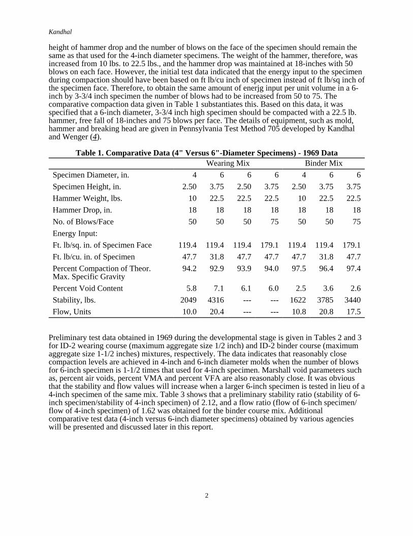
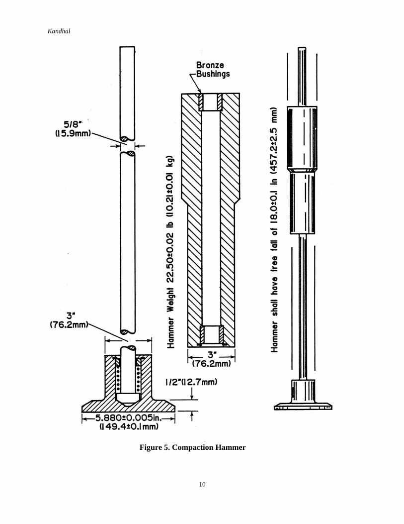
height of hammer drop and the number of blows on the face of the specimen should remain thesame as that used for the 4-inch diameter specimens. The weight of the hammer, therefore, wasincreased from 10 lbs. to 22.5 lbs., and the hammer drop was maintained at 18-inches with 50blows on each face. However, the initial test data indicated that the energy input to the specimenduring compaction should have been based on ft lb/cu inch of specimen instead of ft lb/sq inch ofthe specimen face. Therefore, to obtain the same amount of enerjg input per unit volume in a 6-inch by 3-3/4 inch specimen the number of blows had to be increased from 50 to 75. Thecomparative compaction data given in Table 1 substantiates this. Based on this data, it wasspecified that a 6-inch diameter, 3-3/4 inch high specimen should be compacted with a 22.5 lb.hammer, free fall of 18-inches and 75 blows per face. The details of equipment, such as mold,hammer and breaking head are given in Pennsylvania Test Method 705 developed by Kandhaland Wenger (4).
Table 1. Comparative Data (4" Versus 6"-Diameter Specimens) - 1969 DataWearing Mix Binder Mix
Specimen Diameter, in. 4 6 6 6 4 6 6Specimen Height, in. 2.50 3.75 2.50 3.75 2.50 3.75 3.75Hammer Weight, lbs. 10 22.5 22.5 22.5 10 22.5 22.5Hammer Drop, in. 18 18 18 18 18 18 18No. of Blows/Face 50 50 50 75 50 50 75Energy Input:Ft. lb/sq. in. of Specimen Face 119.4 119.4 119.4 179.1 119.4 119.4 179.1Ft. lb/cu. in. of Specimen 47.7 31.8 47.7 47.7 47.7 31.8 47.7Percent Compaction of Theor.Max. Specific Gravity
94.2 92.9 93.9 94.0 97.5 96.4 97.4
Percent Void Content 5.8 7.1 6.1 6.0 2.5 3.6 2.6Stability, lbs. 2049 4316 --- --- 1622 3785 3440Flow, Units 10.0 20.4 --- --- 10.8 20.8 17.5
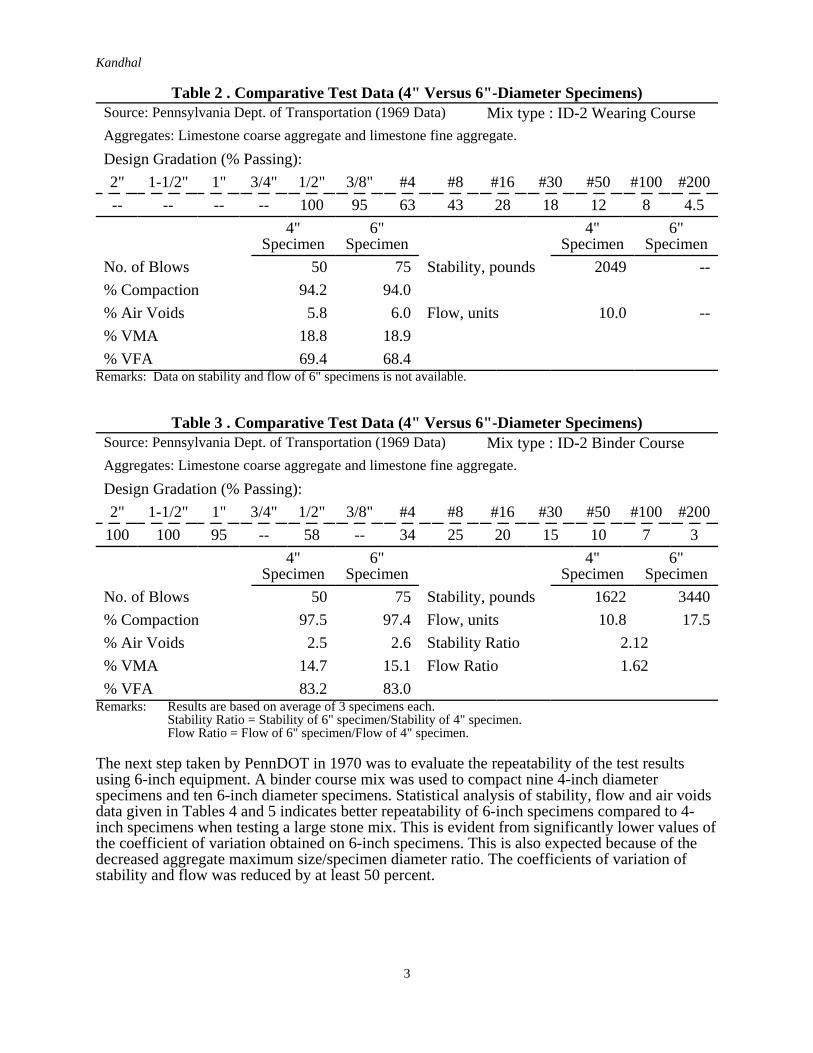
Preliminary test data obtained in 1969 during the developmental stage is given in Tables 2 and 3for ID-2 wearing course (maximum aggregate size 1/2 inch) and ID-2 binder course (maximumaggregate size 1-1/2 inches) mixtures, respectively. The data indicates that reasonably closecompaction levels are achieved in 4-inch and 6-inch diameter molds when the number of blowsfor 6-inch specimen is 1-1/2 times that used for 4-inch specimen. Marshall void parameters suchas, percent air voids, percent VMA and percent VFA are also reasonably close. It was obviousthat the stability and flow values will increase when a larger 6-inch specimen is tested in lieu of a4-inch specimen of the same mix. Table 3 shows that a preliminary stability ratio (stability of 6-inch specimen/stability of 4-inch specimen) of 2.12, and a flow ratio (flow of 6-inch specimen/flow of 4-inch specimen) of 1.62 was obtained for the binder course mix. Additionalcomparative test data (4-inch versus 6-inch diameter specimens) obtained by various agencieswill be presented and discussed later in this report.
Kandhal
3
Table 2 . Comparative Test Data (4" Versus 6"-Diameter Specimens)Source: Pennsylvania Dept. of Transportation (1969 Data) Mix type : ID-2 Wearing CourseAggregates: Limestone coarse aggregate and limestone fine aggregate.
Design Gradation (% Passing):2" 1-1/2" 1" 3/4" 1/2" 3/8" #4 #8 #16 #30 #50 #100 #200-- -- -- -- 100 95 63 43 28 18 12 8 4.5
4"Specimen
6"Specimen
4"Specimen
6"Specimen
No. of Blows 50 75 Stability, pounds 2049 --% Compaction 94.2 94.0% Air Voids 5.8 6.0 Flow, units 10.0 --% VMA 18.8 18.9% VFA 69.4 68.4
Remarks: Data on stability and flow of 6" specimens is not available.
Table 3 . Comparative Test Data (4" Versus 6"-Diameter Specimens)Source: Pennsylvania Dept. of Transportation (1969 Data) Mix type : ID-2 Binder CourseAggregates: Limestone coarse aggregate and limestone fine aggregate.
Design Gradation (% Passing):2" 1-1/2" 1" 3/4" 1/2" 3/8" #4 #8 #16 #30 #50 #100 #200
100 100 95 -- 58 -- 34 25 20 15 10 7 34"
Specimen6"
Specimen4"
Specimen6"
SpecimenNo. of Blows 50 75 Stability, pounds 1622 3440% Compaction 97.5 97.4 Flow, units 10.8 17.5% Air Voids 2.5 2.6 Stability Ratio 2.12% VMA 14.7 15.1 Flow Ratio 1.62% VFA 83.2 83.0
Remarks: Results are based on average of 3 specimens each.Stability Ratio = Stability of 6" specimen/Stability of 4" specimen.Flow Ratio = Flow of 6" specimen/Flow of 4" specimen.
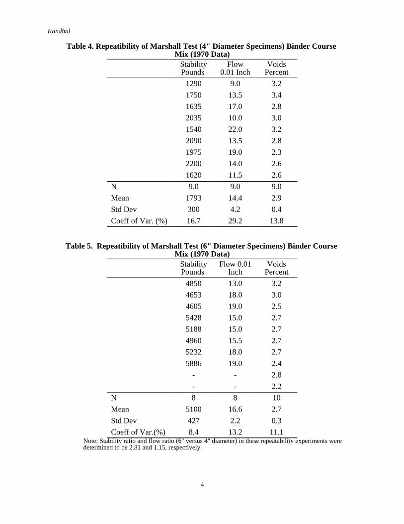
The next step taken by PennDOT in 1970 was to evaluate the repeatability of the test resultsusing 6-inch equipment. A binder course mix was used to compact nine 4-inch diameterspecimens and ten 6-inch diameter specimens. Statistical analysis of stability, flow and air voidsdata given in Tables 4 and 5 indicates better repeatability of 6-inch specimens compared to 4-inch specimens when testing a large stone mix. This is evident from significantly lower values ofthe coefficient of variation obtained on 6-inch specimens. This is also expected because of thedecreased aggregate maximum size/specimen diameter ratio. The coefficients of variation ofstability and flow was reduced by at least 50 percent.
Kandhal
4
Table 4. Repeatibility of Marshall Test (4" Diameter Specimens) Binder Course Mix (1970 Data)
StabilityPounds
Flow0.01 Inch
VoidsPercent
1290 9.0 3.21750 13.5 3.41635 17.0 2.82035 10.0 3.01540 22.0 3.22090 13.5 2.81975 19.0 2.32200 14.0 2.61620 11.5 2.6
N 9.0 9.0 9.0Mean 1793 14.4 2.9Std Dev 300 4.2 0.4Coeff of Var. (%) 16.7 29.2 13.8
Table 5. Repeatibility of Marshall Test (6" Diameter Specimens) Binder Course Mix (1970 Data)
StabilityPounds
Flow 0.01Inch
VoidsPercent
4850 13.0 3.24653 18.0 3.04605 19.0 2.55428 15.0 2.75188 15.0 2.74960 15.5 2.75232 18.0 2.75886 19.0 2.4
- - 2.8- - 2.2
N 8 8 10Mean 5100 16.6 2.7Std Dev 427 2.2 0.3Coeff of Var.(%) 8.4 13.2 11.1
Note: Stability ratio and flow ratio (6" versus 4" diameter) in these repeatability experiments weredetermined to be 2.81 and 1.15, respectively.

Kandhal
5
ASTM Subcommittee D04.20 on Mechanical Tests of Bituminous Mixes appointed a task forcein December 1988 to develop an ASTM standard test for preparing and testing 6-inch diameterMarshall specimens. The author who is chairman of this task force prepared a draft for thisproposed standard which is given in Reference 5. The proposed standard follows ASTM D1559-82 (6) which is intended for 4-inch diameter specimens except the following significantdifferences:
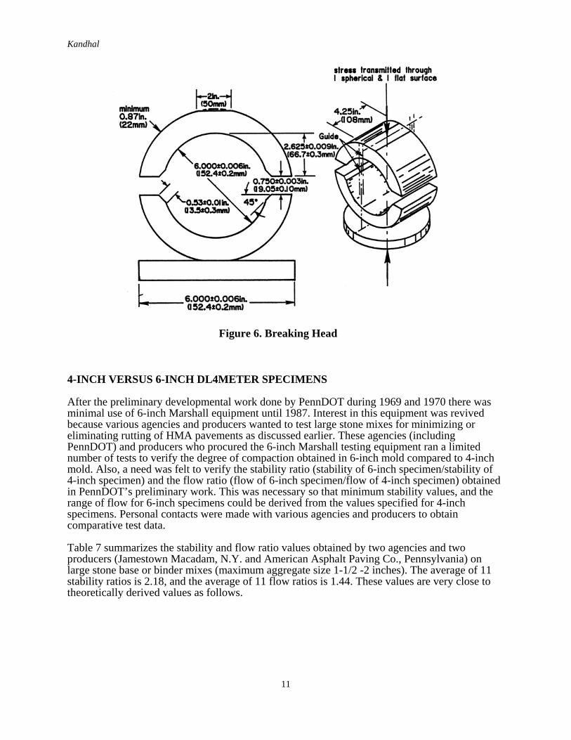
1. Equipment for compacting and testing 6-inch diameter specimens such as, molds andbreaking head (Section 3).
2. Since the hammer weighs 22.5 pounds, only a mechanically operated hammer isspecified (Section 3.3).
3. About 4,050 grams of mix is required to prepare one 6-inch Marshall specimencompared to about 1,200 grams for a 4-inch specimen.
4. The mix is placed in the mold in two approximately equal increments, spading isspecified after each increment (Section 4.5. 1). Past experience has indicated that thisis necessary to avoid honey-combing on the outside surface of the specimen and toobtain the desired density. Mixing and compaction temperatures remain the same as4-inch diameter specimens.
5. The number of blows needed for 6-inch diameter and 3-3/4 inches high specimen is1-1/2 times the number of blows needed for 4-inch diameter and 2-1/2 inches highspecimen to obtain equivalent compaction level (Note 4).
6. Stability correlations ratios have been revised and are given in Table 6. These ratiosare based on percentage increase/decrease in specimen volumes similar to ASTMD1559.
Table 6. Stability Correlations RatiosA
Approximate Thickness of SpecimenB Volume of Specimen,cm3
Correlation Ratio
in. mm3-1/2 88.9 1608 to 1626 1.123-9/16 90.5 1637 to 1665 1.093-5/8 92.1 1666 to 1694 1.06
3-11/16 93.7 1695 to 1723 1.033-3/4 95.2 1724 to 1752 1.00
3-13/16 96.8 1753 to 1781 0.973-7/8 98.4 1782 to 1810 0.95
3-15/16 100.0 1811 to 1839 0.924 101.6 1840 to 1868 0.90
A The measured stability of a specimen multiplied by the ratio for the thickness of the specimen equals the correctedstability for a 3-3/4-in. (95.2 mm) thick specimen.B Volume - thickness relationship is based on a specimen diameter of 6 in. (152.4 mm).
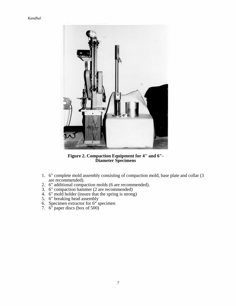
Relative sizes of mold and hammer assembly for compacting 4-inch and 6-inch specimens can beseen in Figure 1. The same mechanical compactor can be used for compacting both types ofspecimens (Figure 2). Figures 3 through 6 show the details of the test equipment.
Since the hammer weighs 22.5 pounds and the number of blows on each side is 75 or 112depending on the anticipated traffic, some crushing of the aggregate at the surface has beenobserved. However, it is believed that its effect on Marshall properties is minimal.

Kandhal
6
Vigorous spading in the mold is necessary to prevent voids near the large stones. The mix shouldnot be allowed to cool below the intended compaction temperature.
At the present time there are two known suppliers of 6-inch Marshall testing equipments in theU.S.A.:
1. Pine Instrument Company101 Industrial DriveGrove City, PA 16127
2. Rainhart CompanyP.O. Box 4533Austin, TX 78765
If a mechanical compactor is already on hand, one needs to buy the following additionalequipment (estimated cost $1,800):
Figure 1. Mold and Hammer Assembly for 4" and 6"-Diameter Specimens (Aggregate Particles of 1" and 2"
Maximum Size Also Shown)
Kandhal
7
1. 6" complete mold assembly consisting of compaction mold, base plate and collar (3are recommended).
2. 6" additional compaction molds (6 are recommended).3. 6" compaction hammer (2 are recommended)4. 6" mold holder (insure that the spring is strong)5. 6" breaking head assembly6. Specimen extractor for 6“ specimen7. 6" paper discs (box of 500)
Figure 2. Compaction Equipment for 4" and 6"-Diameter Specimens

Kandhal
8
Figure 3. Compaction Mold

Kandhal
9
Figure 4. Specimen Mold Holder
Kandhal
10
Figure 5. Compaction Hammer
Kandhal
11
4-INCH VERSUS 6-INCH DL4METER SPECIMENS
After the preliminary developmental work done by PennDOT during 1969 and 1970 there wasminimal use of 6-inch Marshall equipment until 1987. Interest in this equipment was revivedbecause various agencies and producers wanted to test large stone mixes for minimizing oreliminating rutting of HMA pavements as discussed earlier. These agencies (includingPennDOT) and producers who procured the 6-inch Marshall testing equipment ran a limitednumber of tests to verify the degree of compaction obtained in 6-inch mold compared to 4-inchmold. Also, a need was felt to verify the stability ratio (stability of 6-inch specimen/stability of4-inch specimen) and the flow ratio (flow of 6-inch specimen/flow of 4-inch specimen) obtainedin PennDOT’s preliminary work. This was necessary so that minimum stability values, and therange of flow for 6-inch specimens could be derived from the values specified for 4-inchspecimens. Personal contacts were made with various agencies and producers to obtaincomparative test data.
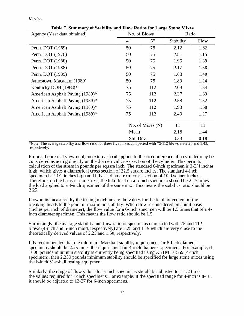
Table 7 summarizes the stability and flow ratio values obtained by two agencies and twoproducers (Jamestown Macadam, N.Y. and American Asphalt Paving Co., Pennsylvania) onlarge stone base or binder mixes (maximum aggregate size 1-1/2 -2 inches). The average of 11stability ratios is 2.18, and the average of 11 flow ratios is 1.44. These values are very close totheoretically derived values as follows.
Figure 6. Breaking Head
Kandhal
12
Table 7. Summary of Stability and Flow Ratios for Large Stone MixesAgency (Year data obtained) No. of Blows Ratio
4" 6" Stability FlowPenn. DOT (1969) 50 75 2.12 1.62Penn. DOT (1970) 50 75 2.81 1.15Penn. DOT (1988) 50 75 1.95 1.39Penn. DOT (1988) 50 75 2.17 1.58Penn. DOT (1989) 50 75 1.68 1.40Jamestown Macadam (1989) 50 75 1.89 1.24Kentucky DOH (1988)* 75 112 2.08 1.34American Asphalt Paving (1989)* 75 112 2.37 1.63American Asphalt Paving (1989)* 75 112 2.58 1.52American Asphalt Paving (1989)* 75 112 1.98 1.68American Asphalt Paving (1989)* 75 112 2.40 1.27
No. of Mixes (N) 11 11Mean 2.18 1.44Std. Dev. 0.33 0.18
*Note: The average stability and flow ratio for these five mixes compacted with 75/112 blows are 2.28 and 1.49,respectively.
From a theoretical viewpoint, an external load applied to the circumference of a cylinder may beconsidered as acting directly on the diametrical cross section of the cylinder. This permitscalculation of the stress in pounds per square inch. The standard 6-inch specimen is 3-3/4 incheshigh, which gives a diametrical cross section of 22.5 square inches. The standard 4-inchspecimen is 2-1/2 inches high and it has a diametrical cross section of 10.0 square inches.Therefore, on the basis of unit stress, the total load on a 6-inch specimen should be 2.25 timesthe load applied to a 4-inch specimen of the same mix. This means the stability ratio should be2.25.
Flow units measured by the testing machine are the values for the total movement of thebreaking heads to the point of maximum stability. When flow is considered on a unit basis(inches per inch of diameter), the flow value for a 6-inch specimen will be 1.5 times that of a 4-inch diameter specimen. This means the flow ratio should be 1.5.
Surprisingly, the average stability and flow ratio of specimens compacted with 75 and 112blows (4-inch and 6-inch mold, respectively) are 2.28 and 1.49 which are very close to thetheoretically derived values of 2.25 and 1.50, respectively.
It is recommended that the minimum Marshall stability requirement for 6-inch diameterspecimens should be 2.25 times the requirement for 4-inch diameter specimens. For example, if1000 pounds minimum stability is currently being specified using ASTM D1559 (4-inchspecimen), then 2,250 pounds minimum stability should be specified for large stone mixes usingthe 6-inch Marshall testing equipment.
Similarly, the range of flow values for 6-inch specimens should be adjusted to 1-1/2 timesthe values required for 4-inch specimens. For example, if the specified range for 4-inch is 8-18,it should be adjusted to 12-27 for 6-inch specimens.
Kandhal
13
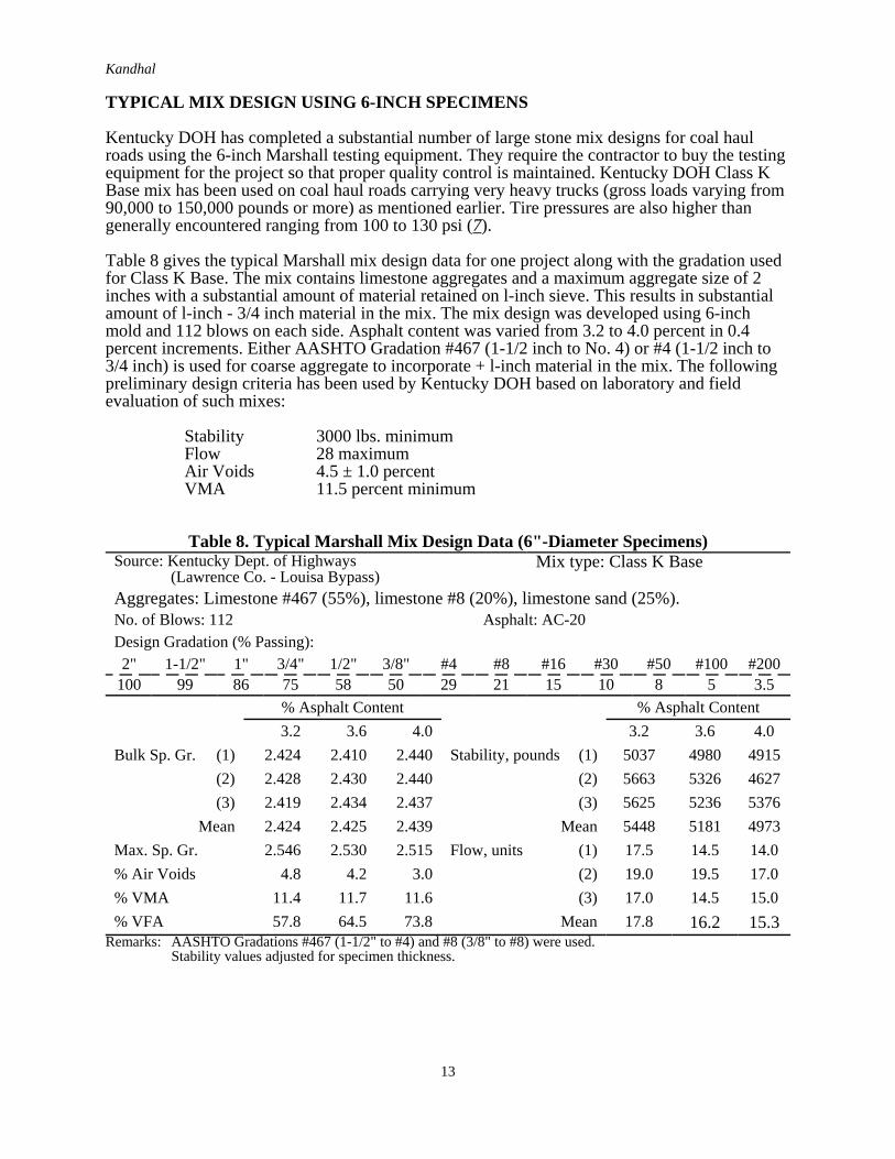
TYPICAL MIX DESIGN USING 6-INCH SPECIMENS
Kentucky DOH has completed a substantial number of large stone mix designs for coal haulroads using the 6-inch Marshall testing equipment. They require the contractor to buy the testingequipment for the project so that proper quality control is maintained. Kentucky DOH Class KBase mix has been used on coal haul roads carrying very heavy trucks (gross loads varying from90,000 to 150,000 pounds or more) as mentioned earlier. Tire pressures are also higher thangenerally encountered ranging from 100 to 130 psi (7).
Table 8 gives the typical Marshall mix design data for one project along with the gradation usedfor Class K Base. The mix contains limestone aggregates and a maximum aggregate size of 2inches with a substantial amount of material retained on l-inch sieve. This results in substantialamount of l-inch - 3/4 inch material in the mix. The mix design was developed using 6-inchmold and 112 blows on each side. Asphalt content was varied from 3.2 to 4.0 percent in 0.4percent increments. Either AASHTO Gradation #467 (1-1/2 inch to No. 4) or #4 (1-1/2 inch to3/4 inch) is used for coarse aggregate to incorporate + l-inch material in the mix. The followingpreliminary design criteria has been used by Kentucky DOH based on laboratory and fieldevaluation of such mixes:
Stability 3000 lbs. minimumFlow 28 maximumAir Voids 4.5 ± 1.0 percentVMA 11.5 percent minimum
Table 8. Typical Marshall Mix Design Data (6"-Diameter Specimens)Source: Kentucky Dept. of Highways (Lawrence Co. - Louisa Bypass)
Mix type: Class K Base
Aggregates: Limestone #467 (55%), limestone #8 (20%), limestone sand (25%).No. of Blows: 112 Asphalt: AC-20Design Gradation (% Passing):2" 1-1/2" 1" 3/4" 1/2" 3/8" #4 #8 #16 #30 #50 #100 #200
100 99 86 75 58 50 29 21 15 10 8 5 3.5% Asphalt Content % Asphalt Content3.2 3.6 4.0 3.2 3.6 4.0
Bulk Sp. Gr. (1) 2.424 2.410 2.440 Stability, pounds (1) 5037 4980 4915(2) 2.428 2.430 2.440 (2) 5663 5326 4627(3) 2.419 2.434 2.437 (3) 5625 5236 5376
Mean 2.424 2.425 2.439 Mean 5448 5181 4973Max. Sp. Gr. 2.546 2.530 2.515 Flow, units (1) 17.5 14.5 14.0% Air Voids 4.8 4.2 3.0 (2) 19.0 19.5 17.0% VMA 11.4 11.7 11.6 (3) 17.0 14.5 15.0% VFA 57.8 64.5 73.8 Mean 17.8 16.2 15.3
Remarks: AASHTO Gradations #467 (1-1/2" to #4) and #8 (3/8" to #8) were used.Stability values adjusted for specimen thickness.

Kandhal
14
FIELD TRIALS AND DATA
Kentucky DOH’s experimental specifications require construction of a control strip (at least 500ft. long and 12 ft. wide) at the beginning of construction of Class K base. Construction of thecontrol strip is accomplished using the same compaction equipment and procedures to be used inthe remainder of the Class K base course. After initial breakdown rolling and 2 completecoverages of the pneumatic-tired intermediate roller, 3 density measurements are made atrandomly selected sites. Measurements are repeated at the same sites after each two subsequentcomplete coverages by the pneumatic-tired roller until no further increase in density is obtained.After the completion of the control strip 10 field density measurements are performed at randomlocations. The target density to be used for the compaction of the remainder Class K base is theaverage of these 10 measurements. However, the target density obtained from the control stripshould be no greater than 97.0 percent nor less than 93.0 percent of the measured maximumspecific gravity (Rice Specific gravity) as determined by AASHTO T209. The minimumacceptable density for the remainder project is:
Single Test: 96.0 percent of the target density.
Moving average of last 10 tests: 98.0 percent of the target density.
Density measurements performed on Louisa Bypass indicate that the compaction wasconsistently within the required range. Average void content of the in-place pavement wasslightly less than 6 percent (7). Limited crushing of coarse surface particles occurred. Due to thecoarse surface texture, nuclear densities were consistently lower than core densities taken at thesame spot. The average nuclear density was about one pound per cubic foot less than coredensity, indicating that calibration is necessary for determination of actual values. It should benoted that a double drum vibratory roller and a 25-ton pneumatic-tired roller (tire pressure up to125 psi) was used for principal compaction.
It is expected that the traffic will densify the pavement to reduce air void content from about 6percent as constructed to the design air void content (4.5 ± 1.0 percent).
Kentucky DOH provides a thin (l”) asphalt concrete surfacing over Class K base to obtain asmooth and impermeable surface. Some technologists believe that 1/2" thick hot sand-asphaltmix can also suffice. In any case, thicker surfacings should be avoided.
Field compaction data from projects in Kentucky and projects in Pennsylvania where large stonemixes were used is given in Reference 5. The test data indicates no significant problem inachieving compaction levels of 92+ percent of the maximum mix specific gravity. Maximumaggregate size and lift thickness were 2" and 4", respectively, on Kentucky projects.Pennsylvania used 1 1/2” maximum aggregate size and 2" lift thickness for the large stone bindercourse mixes (5) All projects are reportedly performing satisfactorily having been in service upto two years.
Kandhal
15
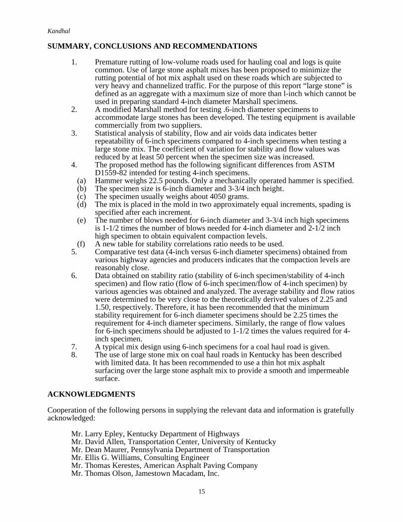
SUMMARY, CONCLUSIONS AND RECOMMENDATIONS
1. Premature rutting of low-volume roads used for hauling coal and logs is quitecommon. Use of large stone asphalt mixes has been proposed to minimize therutting potential of hot mix asphalt used on these roads which are subjected tovery heavy and channelized traffic. For the purpose of this report “large stone” isdefined as an aggregate with a maximum size of more than l-inch which cannot beused in preparing standard 4-inch diameter Marshall specimens.
2. A modified Marshall method for testing .6-inch diameter specimens toaccommodate large stones has been developed. The testing equipment is availablecommercially from two suppliers.
3. Statistical analysis of stability, flow and air voids data indicates betterrepeatability of 6-inch specimens compared to 4-inch specimens when testing alarge stone mix. The coefficient of variation for stability and flow values wasreduced by at least 50 percent when the specimen size was increased.
4. The proposed method has the following significant differences from ASTMD1559-82 intended for testing 4-inch specimens.
(a) Hammer weighs 22.5 pounds. Only a mechanically operated hammer is specified.(b) The specimen size is 6-inch diameter and 3-3/4 inch height.(c) The specimen usually weighs about 4050 grams.(d) The mix is placed in the mold in two approximately equal increments, spading is
specified after each increment.(e) The number of blows needed for 6-inch diameter and 3-3/4 inch high specimens
is 1-1/2 times the number of blows needed for 4-inch diameter and 2-1/2 inchhigh specimen to obtain equivalent compaction levels.
(f) A new table for stability correlations ratio needs to be used.5. Comparative test data (4-inch versus 6-inch diameter specimens) obtained from
various highway agencies and producers indicates that the compaction levels arereasonably close.
6. Data obtained on stability ratio (stability of 6-inch specimen/stability of 4-inchspecimen) and flow ratio (flow of 6-inch specimen/flow of 4-inch specimen) byvarious agencies was obtained and analyzed. The average stability and flow ratioswere determined to be very close to the theoretically derived values of 2.25 and1.50, respectively. Therefore, it has been recommended that the minimumstability requirement for 6-inch diameter specimens should be 2.25 times therequirement for 4-inch diameter specimens. Similarly, the range of flow valuesfor 6-inch specimens should be adjusted to 1-1/2 times the values required for 4-inch specimen.
7. A typical mix design using 6-inch specimens for a coal haul road is given.8. The use of large stone mix on coal haul roads in Kentucky has been described
with limited data. It has been recommended to use a thin hot mix asphaltsurfacing over the large stone asphalt mix to provide a smooth and impermeablesurface.
ACKNOWLEDGMENTS
Cooperation of the following persons in supplying the relevant data and information is gratefullyacknowledged:
Mr. Larry Epley, Kentucky Department of HighwaysMr. David Allen, Transportation Center, University of KentuckyMr. Dean Maurer, Pennsylvania Department of TransportationMr. Ellis G. Williams, Consulting EngineerMr. Thomas Kerestes, American Asphalt Paving CompanyMr. Thomas Olson, Jamestown Macadam, Inc.

Kandhal
16
REFERENCES
1. Kandhal, P.S., “Marshall Mix Design Methods: Current Practices,” Proceedings,Association of Asphalt Paving Technologists, Vol. 54, 1985.
2. Acott, Mike, “The Design of Hot Mix Asphalt for Heavy Duty Pavements,” NationalAsphalt Pavement Association, QIS 111/86, October 1987.
3. “Comparison of 4 and 6-Inch Diameter Molded Specimens,” Pennsylvania Department ofTransportation, Bureau of Materials, Testing and Research, Status Report, February 21,1969.
4. “Marshall Criteria for Compacted Bituminous Specimens,” Pennsylvania Test Method705, Pennsylvania Department of Transportation, Field Test Manual, March 1983.
5. Kandhal, P.S., “Large Stone Asphalt Mixes: Design and Construction,” Paper presentedat the Annual Meeting of the Association of Asphalt Paving Technologists held inAlbuquerque, NM (February 1990).
6. “Resistance to Plastic Flow of Bituminous Mixtures Using Marshall Apparatus,” ASTMD1559-82, American Society for Testing and Materials, Vol. 04.03, 1988.
7. Williams, Ellis G., “Design and Construction of Large Stone HMA Bases in Kentucky,”Hot Mix Asphalt Technology, Winter 1988.


