International Journal of Science and Research (IJSR) ISSN (Online): 2319-7064 Impact Factor (2012): 3.358 Volume 3 Issue 11, November 2014 www.ijsr.net Licensed Under Creative Commons Attribution CC BY Design Transceiver for IEEE 802.15.4 using ZigBee Technology and Matlab/Simulink Pravesh Kumar Agarwal Abstract: ZigBee technology was developed for a wireless personal area network(PAN) aimed at control and military applications with low rate and low power consumption. This paper is mainly focusing on development of Matlab and Simulink model for ZigBee transceiver at physical layer using IEEE 802.15.4 .ZigBee is a low cost, low power, wireless mesh networking. First, the low cost allows the technology to be widely deployed in wireless control and monitoring applications. Second, the low power usage allows longer life with smaller batteries. Third, the mesh networking provides high reliability and more extensive range. ZigBee chip can tested and prepared by shifting the whole work for Matlab environment. This can be done by HDL languages. Here minimum shift keying(MSK) modulation technique is described an analysis of which shows that the theoretical maximum bandwidth efficiency of MSK is 2bits/s/Hz. Keywords: Review of digital modulation schemes, Major functions in transmitter design, Implementation of ZigBee transceiver in Matlab/Simulink, Cocclusion 1. Introduction Wireless personal area network (WPAN) and wireless local area network (WLAN) technologies are growing fast with the new emerging standards being developed. For sometime, Bluetooth was most widely used for short range communications. Now, ZigBee is becoming as an alternative to Bluetooth for devices with low power consumption and for low data rate applications. The Bluetooth standard is a specification for WPAN. Although products based on the Bluetooth standards are often capable of operating at greater distances, the targeted operating area is the one around the individual i.e., within a 10m diameter. Bluetooth utilizes a short range radio link that operates in the 2.4GHz industrial scientific and medical(ISM) band similar to WLAN. However, the radio link in Bluetooth is based on the frequency hop spread spectrum. We know that Bluetooth occupies only 1MHz, the signal changes the centre frequency or hops at the rate of 1600Hz. Bluetooth hops over 79 centre frequencies, so over time the Bluetooth signal actually occupies 79MHz ( [1], [2] ). ZigBee standard is developed by ZigBee Alliance, which has hundreds of member companies, from the semi- conductor industry and software developers to original equipment manufacturers and installers. The ZigBee alliance was formed in 2002 as a nonprofit organization open to everyone who wanted to join. The ZigBee standard has adopted IEEE 802.15.4 as its Physical Layer (PHY) and Medium Access Control (MAC) protocols. Therefore, a ZigBee compliant device is compliant with the IEEE 802.15.4 standard as well. ZigBee standard is specifically developed to address the need for very low cost implementation of low data rate wireless networks with ultralow power consumption. The ZigBee Standard reduced the implementation cost by simplifying the communication protocols and reducing the data rate. The minimum requirements to meet ZigBee and IEEE 802.15.4 specifications are relatively relaxed compared to other standards such as IEEE 802.11, which reduces the complexity and cost of implementing ZigBee compliant transceivers. 1.1 Relationship between ZigBee and IEEE 802.15.4 standard ZigBee wireless networking protocols are shown in Fig.ZigBee protocol layers are based on the Open System Interconnect (OSI) basic reference model. The bottom two networking layers are defined by IEEE 802.15.4 standard. This standard is developed by IEEE 802 standards committee and was initially released in 2003. IEEE 802.15.4 defines the specifications for PHY and MAC layers of wireless networking, but it does not specify any requirements for higher networking layers. The ZigBee standard defines only the networking, applications and security layers of the protocol and adopts IEEE 802.15.4 PHY and MAC layers as a part of the ZigBee networking protocol. Therefore, ZigBee-compliant device conforms to IEEE 802.15.4 as well. Figure 1: ZigBee wireless networkoingprotocol layer The 915MHz and 2.4GHz bands are part of industrial, scientific and medical (ISM) frequency bands. The 915MHz frequency band is used mainly in North America, where as the 2.4GHz band is used worldwide. The Table-1 given Paper ID: OCT141387 1901
Transcript
International Journal of Science and Research (IJSR) ISSN (Online): 2319-7064
Impact Factor (2012): 3.358
Volume 3 Issue 11, November 2014 www.ijsr.net
Licensed Under Creative Commons Attribution CC BY
Design Transceiver for IEEE 802.15.4 using ZigBee Technology and Matlab/Simulink
Pravesh Kumar Agarwal
Abstract: ZigBee technology was developed for a wireless personal area network(PAN) aimed at control and military applications with low rate and low power consumption. This paper is mainly focusing on development of Matlab and Simulink model for ZigBee transceiver at physical layer using IEEE 802.15.4 .ZigBee is a low cost, low power, wireless mesh networking. First, the low cost allows the technology to be widely deployed in wireless control and monitoring applications. Second, the low power usage allows longer life with smaller batteries. Third, the mesh networking provides high reliability and more extensive range. ZigBee chip can tested and prepared by shifting the whole work for Matlab environment. This can be done by HDL languages. Here minimum shift keying(MSK) modulation technique is described an analysis of which shows that the theoretical maximum bandwidth efficiency of MSK is 2bits/s/Hz. Keywords: Review of digital modulation schemes, Major functions in transmitter design, Implementation of ZigBee transceiver in Matlab/Simulink, Cocclusion 1. Introduction Wireless personal area network (WPAN) and wireless local area network (WLAN) technologies are growing fast with the new emerging standards being developed. For sometime, Bluetooth was most widely used for short range communications. Now, ZigBee is becoming as an alternative to Bluetooth for devices with low power consumption and for low data rate applications. The Bluetooth standard is a specification for WPAN. Although products based on the Bluetooth standards are often capable of operating at greater distances, the targeted operating area is the one around the individual i.e., within a 10m diameter. Bluetooth utilizes a short range radio link that operates in the 2.4GHz industrial scientific and medical(ISM) band similar to WLAN. However, the radio link in Bluetooth is based on the frequency hop spread spectrum. We know that Bluetooth occupies only 1MHz, the signal changes the centre frequency or hops at the rate of 1600Hz. Bluetooth hops over 79 centre frequencies, so over time the Bluetooth signal actually occupies 79MHz ( [1], [2] ). ZigBee standard is developed by ZigBee Alliance, which has hundreds of member companies, from the semi-conductor industry and software developers to original equipment manufacturers and installers. The ZigBee alliance was formed in 2002 as a nonprofit organization open to everyone who wanted to join. The ZigBee standard has adopted IEEE 802.15.4 as its Physical Layer (PHY) and Medium Access Control (MAC) protocols. Therefore, a ZigBee compliant device is compliant with the IEEE 802.15.4 standard as well. ZigBee standard is specifically developed to address the need for very low cost implementation of low data rate wireless networks with ultralow power consumption. The ZigBee Standard reduced the implementation cost by simplifying the communication protocols and reducing the data rate. The minimum requirements to meet ZigBee and IEEE 802.15.4 specifications are relatively relaxed compared to other standards such as IEEE 802.11, which reduces the complexity and cost of implementing ZigBee
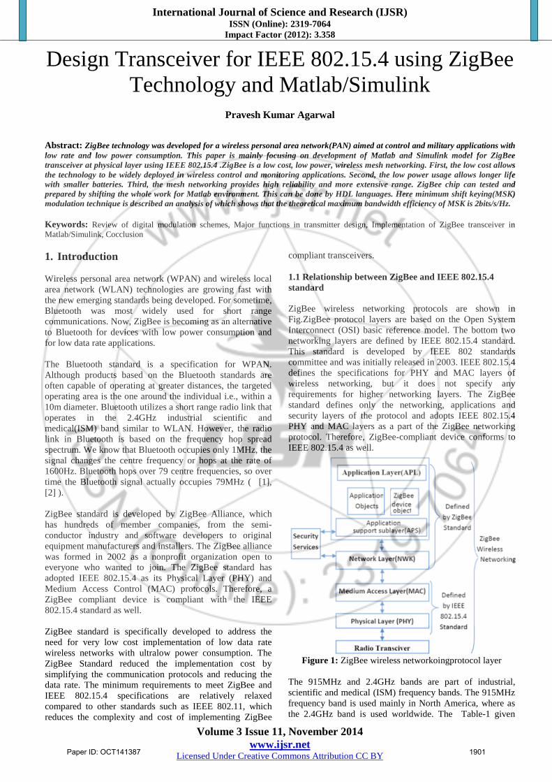
compliant transceivers. 1.1 Relationship between ZigBee and IEEE 802.15.4 standard ZigBee wireless networking protocols are shown in Fig.ZigBee protocol layers are based on the Open System Interconnect (OSI) basic reference model. The bottom two networking layers are defined by IEEE 802.15.4 standard. This standard is developed by IEEE 802 standards committee and was initially released in 2003. IEEE 802.15.4 defines the specifications for PHY and MAC layers of wireless networking, but it does not specify any requirements for higher networking layers. The ZigBee standard defines only the networking, applications and security layers of the protocol and adopts IEEE 802.15.4 PHY and MAC layers as a part of the ZigBee networking protocol. Therefore, ZigBee-compliant device conforms to IEEE 802.15.4 as well.
The 915MHz and 2.4GHz bands are part of industrial, scientific and medical (ISM) frequency bands. The 915MHz frequency band is used mainly in North America, where as the 2.4GHz band is used worldwide. The Table-1 given
International Journal of Science and Research (IJSR) ISSN (Online): 2319-7064
Impact Factor (2012): 3.358
Volume 3 Issue 11, November 2014 www.ijsr.net
Licensed Under Creative Commons Attribution CC BY
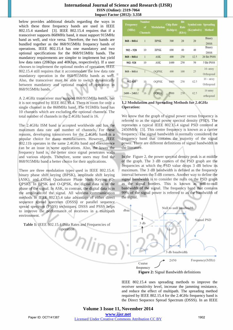
below provides additional details regarding the ways in which these three frequency bands are used in IEEE 802.15.4 standard [3]. IEEE 802.15.4 requires that if a transceiver supports 868MHz band, it must support 915MHz band as well, and vice versa. Therefore, the two bands are bundled together as the 868/915MHz frequency bands of operations. IEEE 802.15.4 has one mandatory and two optional specifications for the 868/915MHz bands. The mandatory requirements are simpler to implement but yield low data rates (20Kbps and 40Kbps, respectively). If a user chooses to implement the optional modes of operation, IEEE 802.15.4 still requires that it accommodate the low data rate mandatory operation in the 868/915MHz bands as well. Also, the transceiver must be able to switch dynamically between mandatory and optional modes of operation in 868/915MHz bands. A 2.4GHz transceiver may support 868/915MHz bands, but it is not required by IEEE 802.15.4. There is room for only a single channel in the 868MHz band. The 915MHz band has 10 channels which are excluding the optional channels. The total number of channels in the 2.4GHz band is 16. The 2.4GHz ISM band is accepted worldwide and has the maximum data rate and number of channels. For these reasons, developing transceivers for the 2.4GHz band is a popular choice for many manufacturers. However, IEEE 802.11b operates in the same 2.4GHz band and coexistence can be an issue in some applications. Also, the lower the frequency band is, the better since signal penetrates walls and various objects. Therefore, some users may find the 868/915MHz band a better choice for their applications. There are three modulation types used in IEEE 802.15.4: binary phase shift keying (BPSK), amplitude shift keying (ASK), and Offset Quadrature Phase Shift Keying (O-QPSK). In BPSK and O-QPSK, the digital data is in the phase of the signal. In ASK, in contrast, the digital data is in the amplitude of the signal. All wireless communication methods in IEEE 802.15.4 take advantage of either direct sequence spread spectrum (DSSS) or parallel sequence spread spectrum (PSSS) techniques. DSSS and PSSS helps to improve the performance of receivers in a multipath environment.
Table 1: IEEE 802.15.4 Data Rates and Frequencies of
operation
1.2 Modulation and Spreading Methods for 2.4GHz Operation: We know that the graph of signal power versus frequency is referred to as the signal power spectral density (PSD). The represents a typical IEEE 802.15.4 signal PSD centered at 2450MHz [3]. This centre frequency is known as a carrier frequency. The signal bandwidth is normally considered the frequency band that contains the majority of the signal power. There are different definitions of signal bandwidth in the literature. In the Figure 2, the power spectral density peak is at middle of the graph. The 3 dB corners of the PSD graph are the frequencies at which the PSD value drops 3 dB below its maximum. The 3 dB bandwidth is defined as the frequency interval between the 3 dB corners. Another way to define the signal bandwidth is to consider the nulls on the PSD graph as the signal borders. This is known as null-to-null bandwidth of the signal. The frequency band that contains 99% of the signal power is referred to as the bandwidth of the signal.
Figure 2: Signal Bandwidth definitions
IEEE 802.15.4 uses spreading methods to improve the receiver sensitivity level, increase the jamming resistance, and reduce the effect of multipath. The spreading method required by IEEE 802.15.4 for the 2.4GHz frequency band is the Direct Sequence Spread Spectrum (DSSS). In an IEEE
International Journal of Science and Research (IJSR) ISSN (Online): 2319-7064
Impact Factor (2012): 3.358
Volume 3 Issue 11, November 2014 www.ijsr.net
Licensed Under Creative Commons Attribution CC BY
802.15.4-specific implementation of DSSS, at every 4 bits of each octet of a PHY protocol data unit (PPDU) are grouped together and referred to as symbol. Then a lookup table is used to map each symbol to a unique 32-bit sequence. This 32-bit sequence is also known as the chip sequence or the pseudorandom noise (PN) sequence. Here, every four bits are mapped to a unique chip sequence; the lookup table contains 16-chip sequences. Each such a chip sequence appears as a random sequence of zeroes and ones. But each sequence is selected by a procedure to minimize its similarity to the other 15 sequences. The similarity of the two sequences measured by calculating the cross-correlation function of two sequences. The cross-correlation is determined by multiplying the sequences together and then calculating the summation of result. A sequence containing 0 and 1 is replaced by its bipolar before calculation of cross-correlation. If x(n) and y(n) are two sequences, the cross-correlation of these two sequences is given below:
The rxy(0) is the calculated cross-correlation of x(n) and y(n) when neither of the sequences is shifted. The higher the absolute value of rxy(0), the higher the similarity of two sequences. If the cross-correlation rxy(0) is equal to zero, it indicates that the sequences x(n) and y(n) are as dissimilar as possible. In this case, the sequences x(n) and y(n) are known as orthogonal sequences. The 16 sequences used in IEEE 802.15.4 are not completely orthogonal and are referred to as near-orthogonal or quasi-orthogonal sequences. 2. Review of Digital Modulation Schemes Here we are analyzing various modulation and demodulation schemes used in digital communication system. For each modulation technique, we analyze the mathematical representation of the waveforms, the signal space, the generation and detection, the spectral content and the performance over the AWGN channel. We can define pass-band signaling as a form of transmission that uses modulation, i.e. the information signal to be transmitted is modulated onto a carrier. Moreover, a pass-band waveform has its frequency spectrum concentrated around the carrier frequency fc. When the modulating signal is digital, we call the process of generating the pass-band signal as digital modulation. In theory, any baseband digital signal can be used to modulate a carrier, directly or indirectly, and generate a pass-band signal. However, as in the case of baseband waveforms, there are specific digital modulations that are more suitable to a given channel or more adequate to satisfy design constraints. Pass band transmission is adequate to communication channels whose frequency response typically have a band-pass response effect, like wireless channels. Some baseband channels can also carry pass band waveforms, usually having moderate-to low frequency carriers. One typical example is the twisted pair cable when used to carry signals from voice-band modems [7]. Similarly to the case of analog modulation, in a digital modulation scheme the digital modulating signal (data bits)
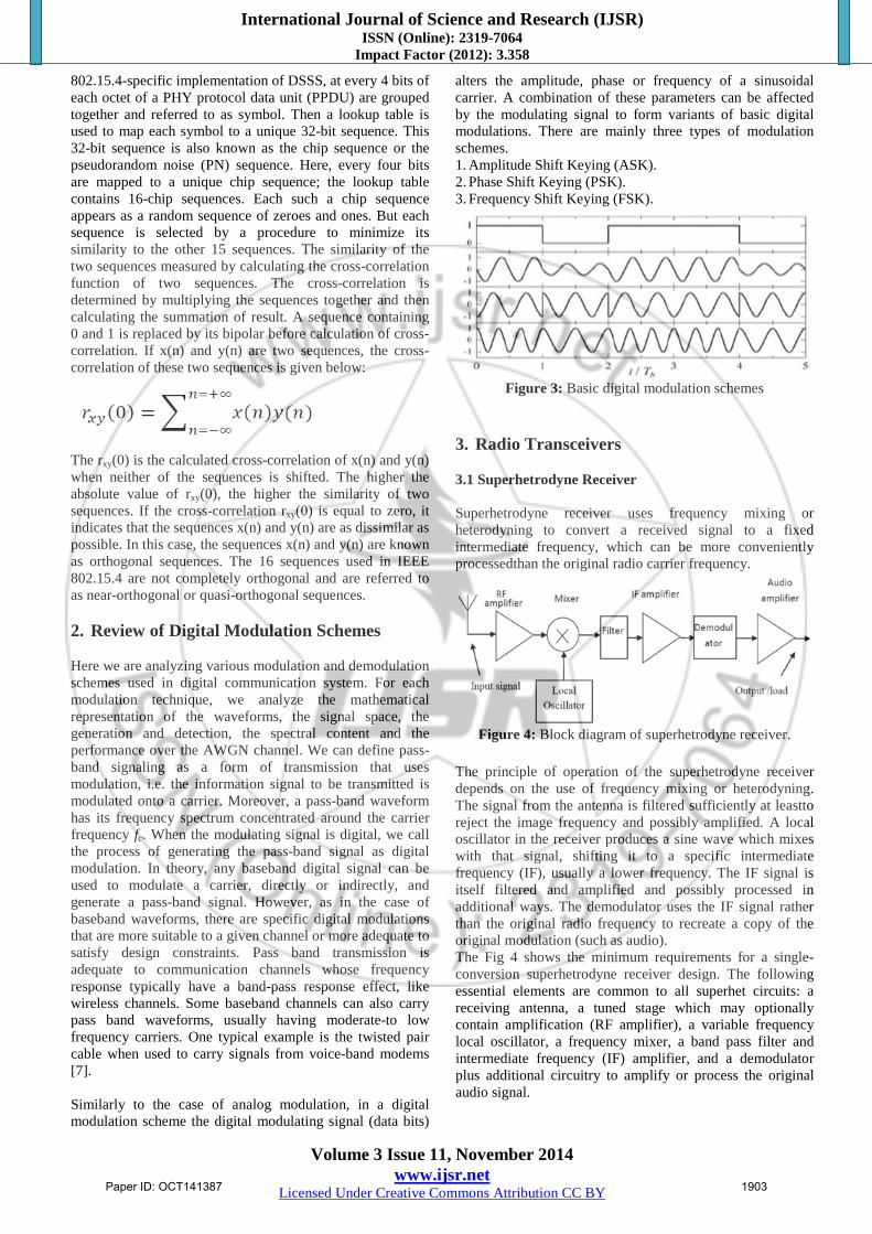
alters the amplitude, phase or frequency of a sinusoidal carrier. A combination of these parameters can be affected by the modulating signal to form variants of basic digital modulations. There are mainly three types of modulation schemes. 1. Amplitude Shift Keying (ASK). 2. Phase Shift Keying (PSK). 3. Frequency Shift Keying (FSK).
Figure 3: Basic digital modulation schemes
3. Radio Transceivers 3.1 Superhetrodyne Receiver Superhetrodyne receiver uses frequency mixing or heterodyning to convert a received signal to a fixed intermediate frequency, which can be more conveniently processedthan the original radio carrier frequency.
Figure 4: Block diagram of superhetrodyne receiver.
The principle of operation of the superhetrodyne receiver depends on the use of frequency mixing or heterodyning. The signal from the antenna is filtered sufficiently at leastto reject the image frequency and possibly amplified. A local oscillator in the receiver produces a sine wave which mixes with that signal, shifting it to a specific intermediate frequency (IF), usually a lower frequency. The IF signal is itself filtered and amplified and possibly processed in additional ways. The demodulator uses the IF signal rather than the original radio frequency to recreate a copy of the original modulation (such as audio). The Fig 4 shows the minimum requirements for a single-conversion superhetrodyne receiver design. The following essential elements are common to all superhet circuits: a receiving antenna, a tuned stage which may optionally contain amplification (RF amplifier), a variable frequency local oscillator, a frequency mixer, a band pass filter and intermediate frequency (IF) amplifier, and a demodulator plus additional circuitry to amplify or process the original audio signal.
International Journal of Science and Research (IJSR) ISSN (Online): 2319-7064
Impact Factor (2012): 3.358
Volume 3 Issue 11, November 2014 www.ijsr.net
Licensed Under Creative Commons Attribution CC BY
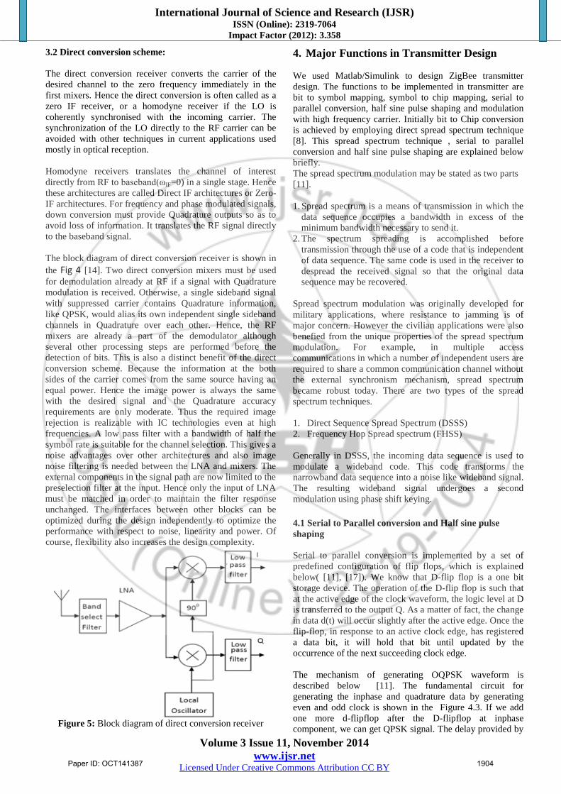
3.2 Direct conversion scheme: The direct conversion receiver converts the carrier of the desired channel to the zero frequency immediately in the first mixers. Hence the direct conversion is often called as a zero IF receiver, or a homodyne receiver if the LO is coherently synchronised with the incoming carrier. The synchronization of the LO directly to the RF carrier can be avoided with other techniques in current applications used mostly in optical reception. Homodyne receivers translates the channel of interest directly from RF to baseband(ωIF=0) in a single stage. Hence these architectures are called Direct IF architectures or Zero-IF architectures. For frequency and phase modulated signals, down conversion must provide Quadrature outputs so as to avoid loss of information. It translates the RF signal directly to the baseband signal. The block diagram of direct conversion receiver is shown in the Fig 4 [14]. Two direct conversion mixers must be used for demodulation already at RF if a signal with Quadrature modulation is received. Otherwise, a single sideband signal with suppressed carrier contains Quadrature information, like QPSK, would alias its own independent single sideband channels in Quadrature over each other. Hence, the RF mixers are already a part of the demodulator although several other processing steps are performed before the detection of bits. This is also a distinct benefit of the direct conversion scheme. Because the information at the both sides of the carrier comes from the same source having an equal power. Hence the image power is always the same with the desired signal and the Quadrature accuracy requirements are only moderate. Thus the required image rejection is realizable with IC technologies even at high frequencies. A low pass filter with a bandwidth of half the symbol rate is suitable for the channel selection. This gives a noise advantages over other architectures and also image noise filtering is needed between the LNA and mixers. The external components in the signal path are now limited to the preselection filter at the input. Hence only the input of LNA must be matched in order to maintain the filter response unchanged. The interfaces between other blocks can be optimized during the design independently to optimize the performance with respect to noise, linearity and power. Of course, flexibility also increases the design complexity.
Figure 5: Block diagram of direct conversion receiver
4. Major Functions in Transmitter Design We used Matlab/Simulink to design ZigBee transmitter design. The functions to be implemented in transmitter are bit to symbol mapping, symbol to chip mapping, serial to parallel conversion, half sine pulse shaping and modulation with high frequency carrier. Initially bit to Chip conversion is achieved by employing direct spread spectrum technique [8]. This spread spectrum technique , serial to parallel conversion and half sine pulse shaping are explained below briefly. The spread spectrum modulation may be stated as two parts [11]. 1. Spread spectrum is a means of transmission in which the
data sequence occupies a bandwidth in excess of the minimum bandwidth necessary to send it.
2. The spectrum spreading is accomplished before transmission through the use of a code that is independent of data sequence. The same code is used in the receiver to despread the received signal so that the original data sequence may be recovered.
Spread spectrum modulation was originally developed for military applications, where resistance to jamming is of major concern. However the civilian applications were also benefied from the unique properties of the spread spectrum modulation. For example, in multiple access communications in which a number of independent users are required to share a common communication channel without the external synchronism mechanism, spread spectrum became robust today. There are two types of the spread spectrum techniques. 1. Direct Sequence Spread Spectrum (DSSS) 2. Frequency Hop Spread spectrum (FHSS) Generally in DSSS, the incoming data sequence is used to modulate a wideband code. This code transforms the narrowband data sequence into a noise like wideband signal. The resulting wideband signal undergoes a second modulation using phase shift keying. 4.1 Serial to Parallel conversion and Half sine pulse shaping Serial to parallel conversion is implemented by a set of predefined configuration of flip flops, which is explained below( [11], [17]). We know that D-flip flop is a one bit storage device. The operation of the D-flip flop is such that at the active edge of the clock waveform, the logic level at D is transferred to the output Q. As a matter of fact, the change in data d(t) will occur slightly after the active edge. Once the flip-flop, in response to an active clock edge, has registered a data bit, it will hold that bit until updated by the occurrence of the next succeeding clock edge. The mechanism of generating OQPSK waveform is described below [11]. The fundamental circuit for generating the inphase and quadrature data by generating even and odd clock is shown in the Figure 4.3. If we add one more d-flipflop after the D-flipflop at inphase component, we can get QPSK signal. The delay provided by
International Journal of Science and Research (IJSR) ISSN (Online): 2319-7064
Impact Factor (2012): 3.358
Volume 3 Issue 11, November 2014 www.ijsr.net
Licensed Under Creative Commons Attribution CC BY
the D-flipflop should be half of bit duration.
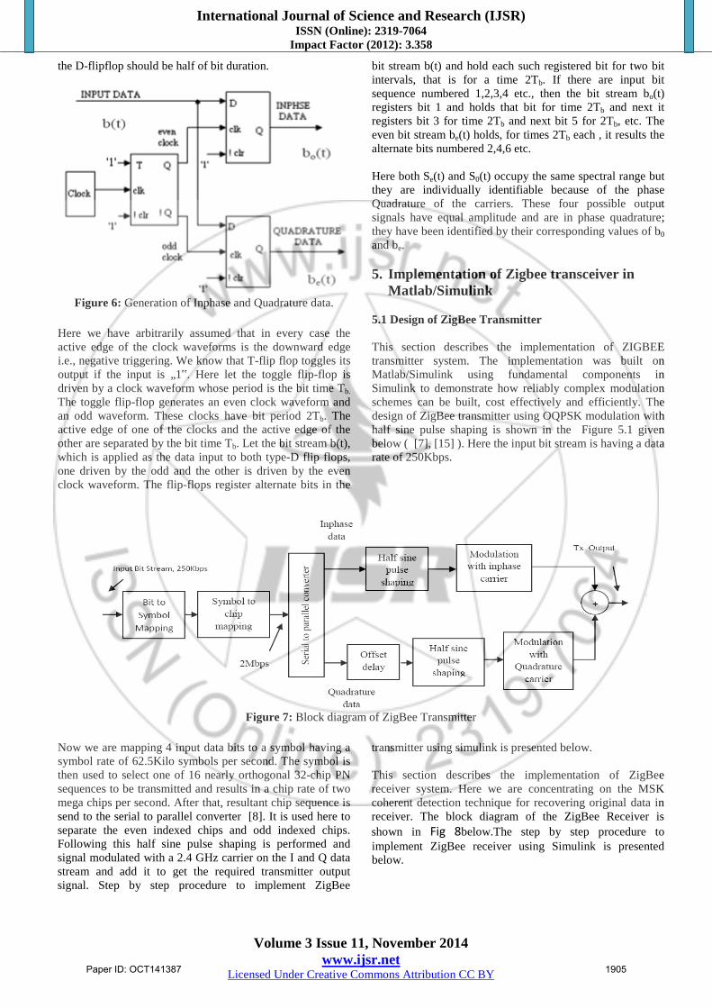
Figure 6: Generation of Inphase and Quadrature data.
Here we have arbitrarily assumed that in every case the active edge of the clock waveforms is the downward edge i.e., negative triggering. We know that T-flip flop toggles its output if the input is „1‟. Here let the toggle flip-flop is driven by a clock waveform whose period is the bit time Tb. The toggle flip-flop generates an even clock waveform and an odd waveform. These clocks have bit period 2Tb. The active edge of one of the clocks and the active edge of the other are separated by the bit time Tb. Let the bit stream b(t), which is applied as the data input to both type-D flip flops, one driven by the odd and the other is driven by the even clock waveform. The flip-flops register alternate bits in the
bit stream b(t) and hold each such registered bit for two bit intervals, that is for a time 2Tb. If there are input bit sequence numbered 1,2,3,4 etc., then the bit stream bo(t) registers bit 1 and holds that bit for time 2Tb and next it registers bit 3 for time 2Tb and next bit 5 for 2Tb, etc. The even bit stream be(t) holds, for times 2Tb each , it results the alternate bits numbered 2,4,6 etc. Here both Se(t) and S0(t) occupy the same spectral range but they are individually identifiable because of the phase Quadrature of the carriers. These four possible output signals have equal amplitude and are in phase quadrature; they have been identified by their corresponding values of b0 and be. 5. Implementation of Zigbee transceiver in
Matlab/Simulink 5.1 Design of ZigBee Transmitter This section describes the implementation of ZIGBEE transmitter system. The implementation was built on Matlab/Simulink using fundamental components in Simulink to demonstrate how reliably complex modulation schemes can be built, cost effectively and efficiently. The design of ZigBee transmitter using OQPSK modulation with half sine pulse shaping is shown in the Figure 5.1 given below ( [7], [15] ). Here the input bit stream is having a data rate of 250Kbps.
Figure 7: Block diagram of ZigBee Transmitter
Now we are mapping 4 input data bits to a symbol having a symbol rate of 62.5Kilo symbols per second. The symbol is then used to select one of 16 nearly orthogonal 32-chip PN sequences to be transmitted and results in a chip rate of two mega chips per second. After that, resultant chip sequence is send to the serial to parallel converter [8]. It is used here to separate the even indexed chips and odd indexed chips. Following this half sine pulse shaping is performed and signal modulated with a 2.4 GHz carrier on the I and Q data stream and add it to get the required transmitter output signal. Step by step procedure to implement ZigBee
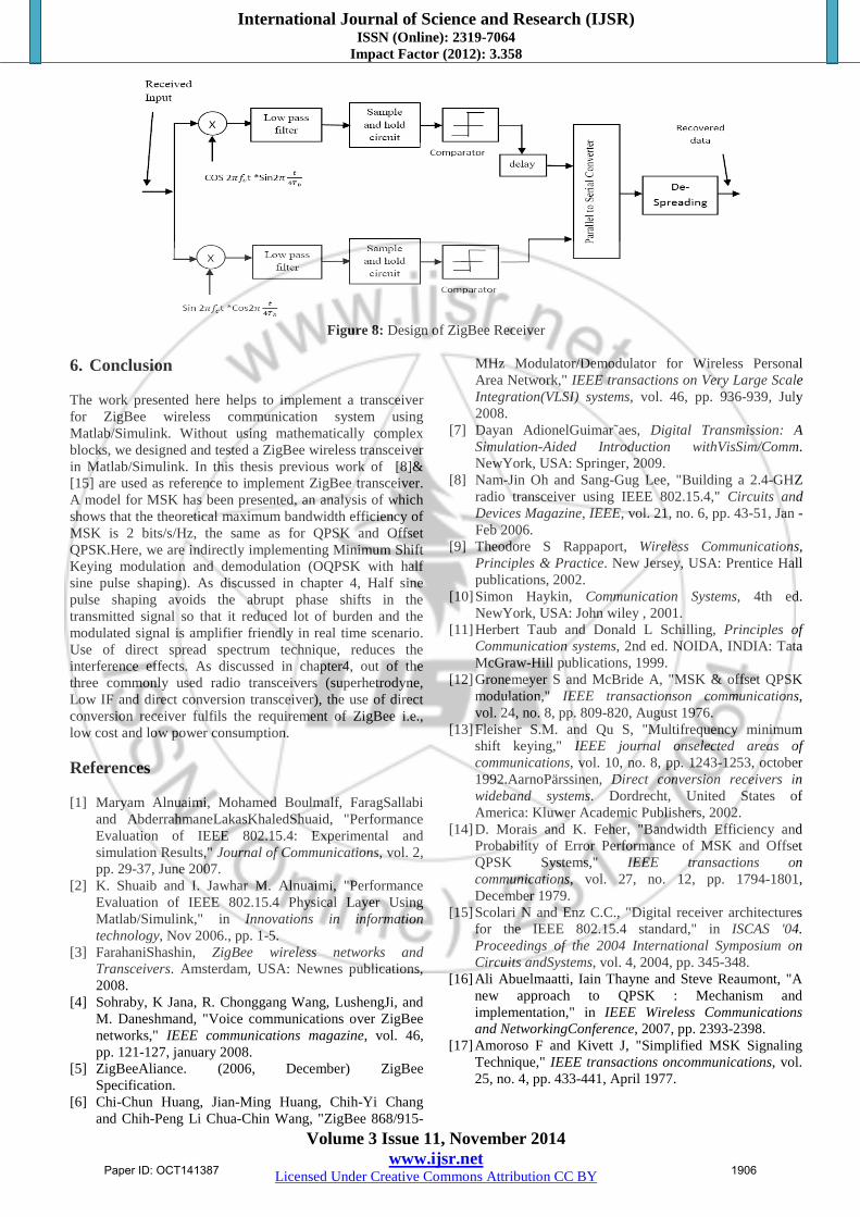
transmitter using simulink is presented below. This section describes the implementation of ZigBee receiver system. Here we are concentrating on the MSK coherent detection technique for recovering original data in receiver. The block diagram of the ZigBee Receiver is shown in Fig 8below.The step by step procedure to implement ZigBee receiver using Simulink is presented below.
International Journal of Science and Research (IJSR) ISSN (Online): 2319-7064
Impact Factor (2012): 3.358
Volume 3 Issue 11, November 2014 www.ijsr.net
Licensed Under Creative Commons Attribution CC BY
Figure 8: Design of ZigBee Receiver
6. Conclusion The work presented here helps to implement a transceiver for ZigBee wireless communication system using Matlab/Simulink. Without using mathematically complex blocks, we designed and tested a ZigBee wireless transceiver in Matlab/Simulink. In this thesis previous work of [8]& [15] are used as reference to implement ZigBee transceiver. A model for MSK has been presented, an analysis of which shows that the theoretical maximum bandwidth efficiency of MSK is 2 bits/s/Hz, the same as for QPSK and Offset QPSK.Here, we are indirectly implementing Minimum Shift Keying modulation and demodulation (OQPSK with half sine pulse shaping). As discussed in chapter 4, Half sine pulse shaping avoids the abrupt phase shifts in the transmitted signal so that it reduced lot of burden and the modulated signal is amplifier friendly in real time scenario. Use of direct spread spectrum technique, reduces the interference effects. As discussed in chapter4, out of the three commonly used radio transceivers (superhetrodyne, Low IF and direct conversion transceiver), the use of direct conversion receiver fulfils the requirement of ZigBee i.e., low cost and low power consumption. References
and AbderrahmaneLakasKhaledShuaid, "Performance Evaluation of IEEE 802.15.4: Experimental and simulation Results," Journal of Communications, vol. 2, pp. 29-37, June 2007.
[2] K. Shuaib and I. Jawhar M. Alnuaimi, "Performance Evaluation of IEEE 802.15.4 Physical Layer Using Matlab/Simulink," in Innovations in information technology, Nov 2006., pp. 1-5.
[4] Sohraby, K Jana, R. Chonggang Wang, LushengJi, and M. Daneshmand, "Voice communications over ZigBee networks," IEEE communications magazine, vol. 46, pp. 121-127, january 2008.
[6] Chi-Chun Huang, Jian-Ming Huang, Chih-Yi Chang and Chih-Peng Li Chua-Chin Wang, "ZigBee 868/915-
MHz Modulator/Demodulator for Wireless Personal Area Network," IEEE transactions on Very Large Scale Integration(VLSI) systems, vol. 46, pp. 936-939, July 2008.
[7] Dayan AdionelGuimar˜aes, Digital Transmission: A Simulation-Aided Introduction withVisSim/Comm. NewYork, USA: Springer, 2009.
[8] Nam-Jin Oh and Sang-Gug Lee, "Building a 2.4-GHZ radio transceiver using IEEE 802.15.4," Circuits and Devices Magazine, IEEE, vol. 21, no. 6, pp. 43-51, Jan - Feb 2006.
[9] Theodore S Rappaport, Wireless Communications, Principles & Practice. New Jersey, USA: Prentice Hall publications, 2002.
[10] Simon Haykin, Communication Systems, 4th ed. NewYork, USA: John wiley , 2001.
[11] Herbert Taub and Donald L Schilling, Principles of Communication systems, 2nd ed. NOIDA, INDIA: Tata McGraw-Hill publications, 1999.
[12] Gronemeyer S and McBride A, "MSK & offset QPSK modulation," IEEE transactionson communications, vol. 24, no. 8, pp. 809-820, August 1976.
[13] Fleisher S.M. and Qu S, "Multifrequency minimum shift keying," IEEE journal onselected areas of communications, vol. 10, no. 8, pp. 1243-1253, october 1992.AarnoPärssinen, Direct conversion receivers in wideband systems. Dordrecht, United States of America: Kluwer Academic Publishers, 2002.
[14] D. Morais and K. Feher, "Bandwidth Efficiency and Probability of Error Performance of MSK and Offset QPSK Systems," IEEE transactions on communications, vol. 27, no. 12, pp. 1794-1801, December 1979.
[15] Scolari N and Enz C.C., "Digital receiver architectures for the IEEE 802.15.4 standard," in ISCAS '04. Proceedings of the 2004 International Symposium on Circuits andSystems, vol. 4, 2004, pp. 345-348.
[16] Ali Abuelmaatti, Iain Thayne and Steve Reaumont, "A new approach to QPSK : Mechanism and implementation," in IEEE Wireless Communications and NetworkingConference, 2007, pp. 2393-2398.
[17] Amoroso F and Kivett J, "Simplified MSK Signaling Technique," IEEE transactions oncommunications, vol. 25, no. 4, pp. 433-441, April 1977.