57
Chipseal Design and Materials Stephen Van De Bogert Western States Asphalt
| Date post: | 27-May-2018 |
| Category: |
Documents |
| Upload: | phungkhuong |
| View: | 214 times |
| Download: | 0 times |
Chipseal Design and Materials
Stephen Van De Bogert Western States Asphalt

Discussion Topics
• Mcleod Chipseal Design ( Mndot version) • Aggregate Requirements • Binders • Alternative to a Chipseal
– Maintenance Seal
• Review of Spokane’s FA-‐2 Seals

Chipseal Design Method
• What should this design method do? – 1. Give amount of aggregate needed to cover 1 sq. yd² a single stone thick
– 2. Give starting binder application rate • Starting rate would yield 60% to 70% embedment if no absorption by pavement
• Must adjust for current conditions of pavement – Recommendation for crew to use to help adjust for traffic and conditions of pavement
Design
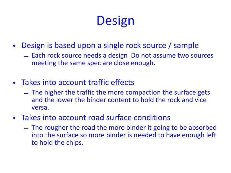
• Design is based upon a single rock source / sample – Each rock source needs a design Do not assume two sources meeting the same spec are close enough.
• Takes into account traffic effects – The higher the traffic the more compaction the surface gets and the lower the binder content to hold the rock and vice versa.
• Takes into account road surface conditions – The rougher the road the more binder it going to be absorbed into the surface so more binder is needed to have enough left to hold the chips.
• Chip Seal Design Program http://www.dot.state.mn.us/materials/researchsealcoat.html
• Minnesota Seal Coat Handbook http://www.lrrb.org/pdf/200634.pdf
Reference Source
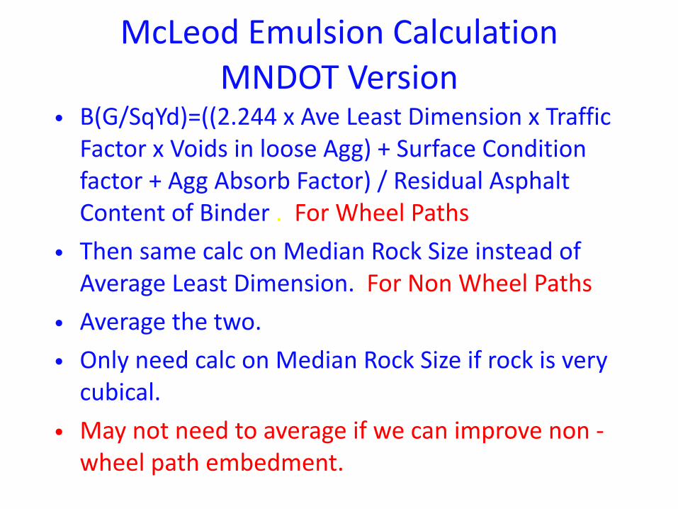
McLeod Emulsion Calculation MNDOT Version
• B(G/SqYd)=((2.244 x Ave Least Dimension x Traffic Factor x Voids in loose Agg) + Surface Condition factor + Agg Absorb Factor) / Residual Asphalt Content of Binder . For Wheel Paths
• Then same calc on Median Rock Size instead of Average Least Dimension. For Non Wheel Paths
• Average the two. • Only need calc on Median Rock Size if rock is very cubical.
• May not need to average if we can improve non -‐wheel path embedment.
Precision is the Key to Success
• The higher the number of sieves used to grade the material the more accurate the design.
• The more cubical the rock the more precise the design.
• Accurate traffic count. • Accurate Road evaluation.
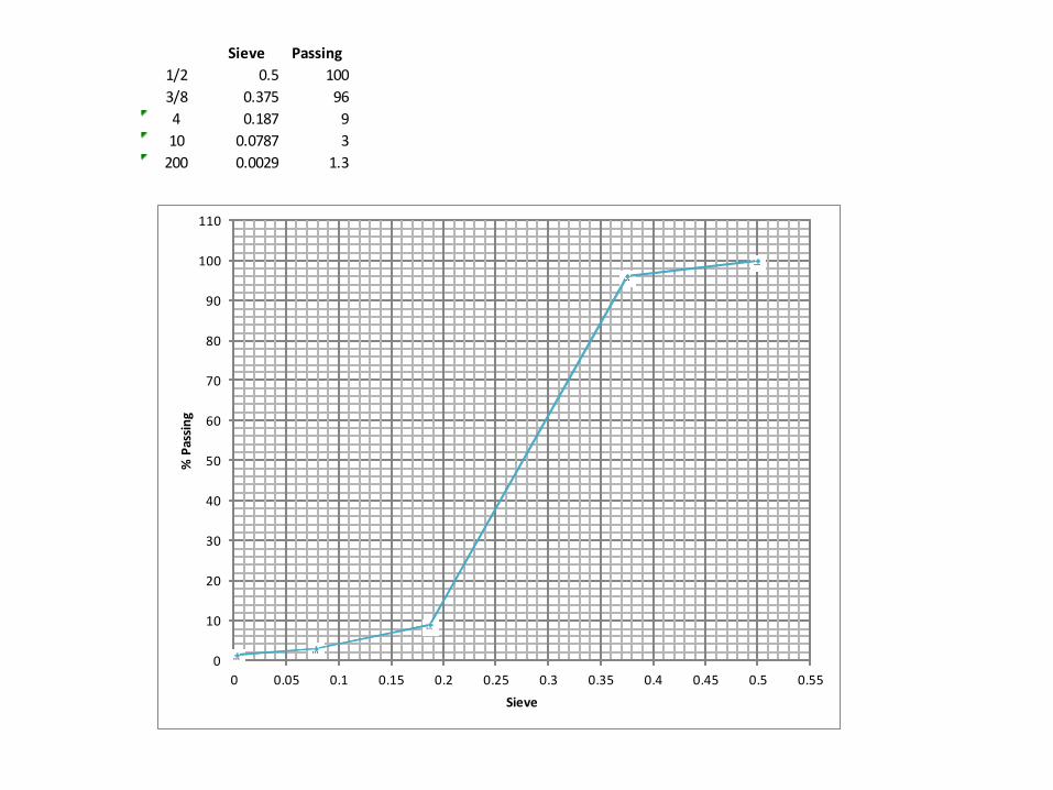
Sieve Passing1/2 0.5 1003/8 0.375 964 0.187 910 0.0787 3200 0.0029 1.3
0
10
20
30
40
50
60
70
80
90
100
110
0 0.05 0.1 0.15 0.2 0.25 0.3 0.35 0.4 0.45 0.5 0.55
%+Passin
g
Sieve

Sieve Passing1/2 0.5 1003/8 0.375 961/4 0.25 204 0.187 910 0.0787 3200 0.0029 1.3
0
10
20
30
40
50
60
70
80
90
100
110
0 0.05 0.1 0.15 0.2 0.25 0.3 0.35 0.4 0.45 0.5 0.55
%+Passin
g
Sieve
0
10
20
30
40
50
60
70
80
90
100
110
0 0.05 0.1 0.15 0.2 0.25 0.3 0.35 0.4 0.45 0.5 0.55
%+Passin
g
Sieve

Tests run on Aggregate for design
• Gradation – Binder ; for embedment • Loose Unit Weight – To Calc. Voids / room for binder
• Specific Gravity – To Calc. Voids • Absorption – Binder; for loss in absorb. • Flakiness Index-‐ Binder; for functional embedment. How high will the chips sit up when finally embedded.
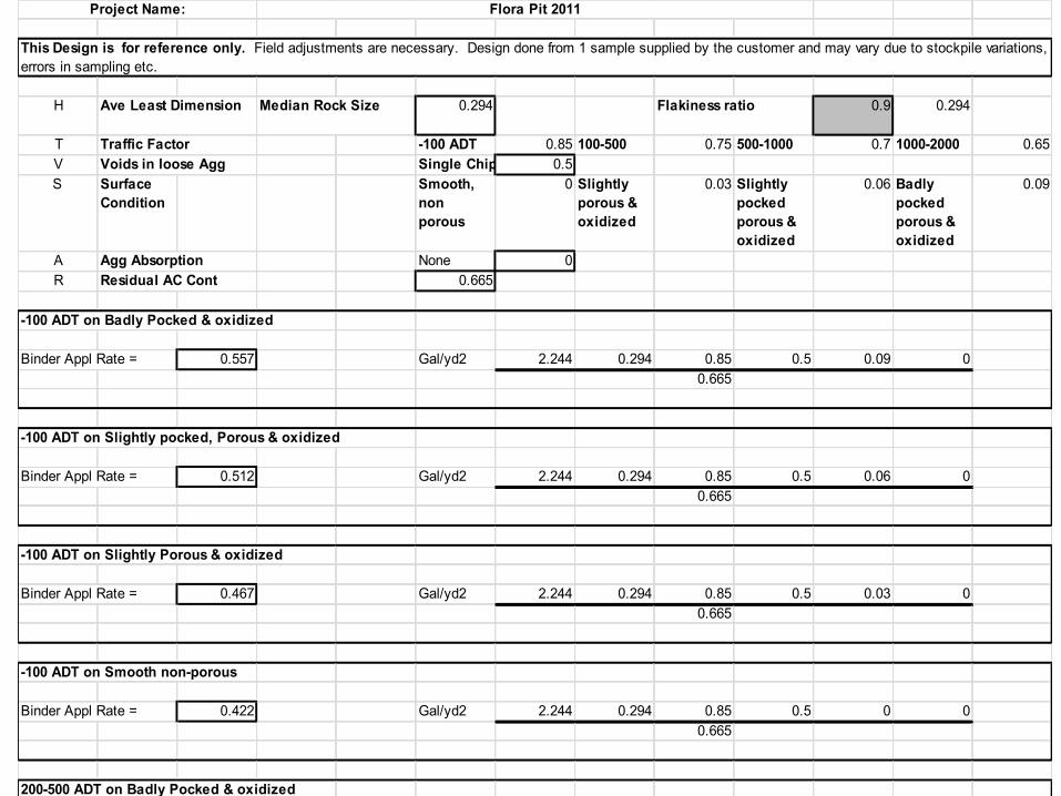
H Ave Least Dimension 0.294 Flakiness ratio 0.9 0.294
T Traffic Factor -100 ADT 0.85 100-500 0.75 500-1000 0.7 1000-2000 0.65V Voids in loose Agg Single Chip 0.5S Surface
ConditionSmooth, non porous
0 Slightly porous & oxidized
0.03 Slightly pocked porous & oxidized
0.06 Badly pocked porous & oxidized
0.09
A Agg Absorption None 0R Residual AC Cont 0.665
-100 ADT on Badly Pocked & oxidized
Binder Appl Rate = 0.557 Gal/yd2 2.244 0.294 0.85 0.5 0.09 00.665
-100 ADT on Slightly pocked, Porous & oxidized
Binder Appl Rate = 0.512 Gal/yd2 2.244 0.294 0.85 0.5 0.06 00.665
-100 ADT on Slightly Porous & oxidized
Binder Appl Rate = 0.467 Gal/yd2 2.244 0.294 0.85 0.5 0.03 00.665
-100 ADT on Smooth non-porous
Binder Appl Rate = 0.422 Gal/yd2 2.244 0.294 0.85 0.5 0 00.665
200-500 ADT on Badly Pocked & oxidized
Binder Appl Rate = 0.507 Gal/yd2 2.244 0.294 0.75 0.5 0.09 00.665
200-500 ADT on Slightly Pocked, Porous & oxidized
Binder Appl Rate = 0.462 Gal/yd2 2.244 0.294 0.75 0.5 0.06 00.665
Project Name:
Median Rock Size
This Design is for reference only. Field adjustments are necessary. Design done from 1 sample supplied by the customer and may vary due to stockpile variations, errors in sampling etc.
Flora Pit 2011
Project Name: Flora Pit 2011
This Design is for reference only. Field adjustments are necessary. Design done from 1 sample supplied by the customer and may vary due to stockpile variations, errors in sampling etc.
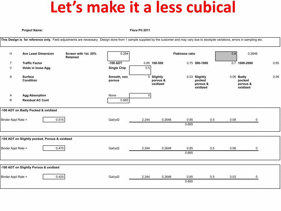
H Ave Least Dimension Screen with 1st. 20% Retained
0.294 Flakiness ratio 0.8 0.2646
T Traffic Factor -100 ADT 0.85 100-500 0.75 500-1000 0.7 1000-2000 0.65V Voids in loose Agg Single Chip 0.5
S Surface Condition
Smooth, non porous
0 Slightly porous & oxidized
0.03 Slightly pocked porous & oxidized
0.06 Badly pocked porous & oxidized
0.09
A Agg Absorption None 0R Residual AC Cont 0.665
-100 ADT on Badly Pocked & oxidized
Binder Appl Rate = 0.515 Gal/yd2 2.244 0.2646 0.85 0.5 0.09 0 0.665
-100 ADT on Slightly pocked, Porous & oxidized
Binder Appl Rate = 0.470 Gal/yd2 2.244 0.2646 0.85 0.5 0.06 0 0.665
-100 ADT on Slightly Porous & oxidized
Binder Appl Rate = 0.425 Gal/yd2 2.244 0.2646 0.85 0.5 0.03 0 0.665
Let’s make it a less cubical
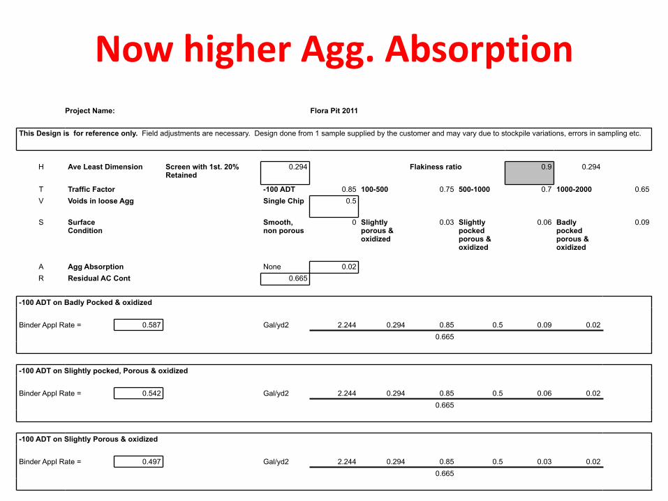
Project Name: Flora Pit 2011
This Design is for reference only. Field adjustments are necessary. Design done from 1 sample supplied by the customer and may vary due to stockpile variations, errors in sampling etc.
H Ave Least Dimension Screen with 1st. 20% Retained
0.294 Flakiness ratio 0.9 0.294
T Traffic Factor -100 ADT 0.85 100-500 0.75 500-1000 0.7 1000-2000 0.65V Voids in loose Agg Single Chip 0.5
S Surface Condition
Smooth, non porous
0 Slightly porous & oxidized
0.03 Slightly pocked porous & oxidized
0.06 Badly pocked porous & oxidized
0.09
A Agg Absorption None 0.02R Residual AC Cont 0.665
-100 ADT on Badly Pocked & oxidized
Binder Appl Rate = 0.587 Gal/yd2 2.244 0.294 0.85 0.5 0.09 0.02 0.665
-100 ADT on Slightly pocked, Porous & oxidized
Binder Appl Rate = 0.542 Gal/yd2 2.244 0.294 0.85 0.5 0.06 0.02 0.665
-100 ADT on Slightly Porous & oxidized
Binder Appl Rate = 0.497 Gal/yd2 2.244 0.294 0.85 0.5 0.03 0.02 0.665
Now higher Agg. Absorption
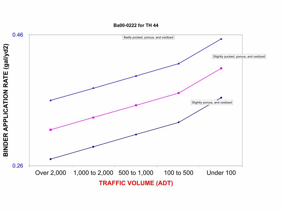
Ba00-0222 for TH 44
BIN
DER
APP
LIC
ATIO
N R
ATE
(gal
/yd2
)
0.26
0.46
TRAFFIC VOLUME (ADT)Over 2,000 1,000 to 2,000 500 to 1,000 100 to 500 Under 100
Badly pocked, porous, and oxidized
Slightly pocked, porous, and oxidized
Slightly porous, and oxidized
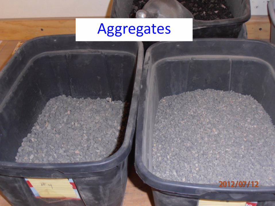
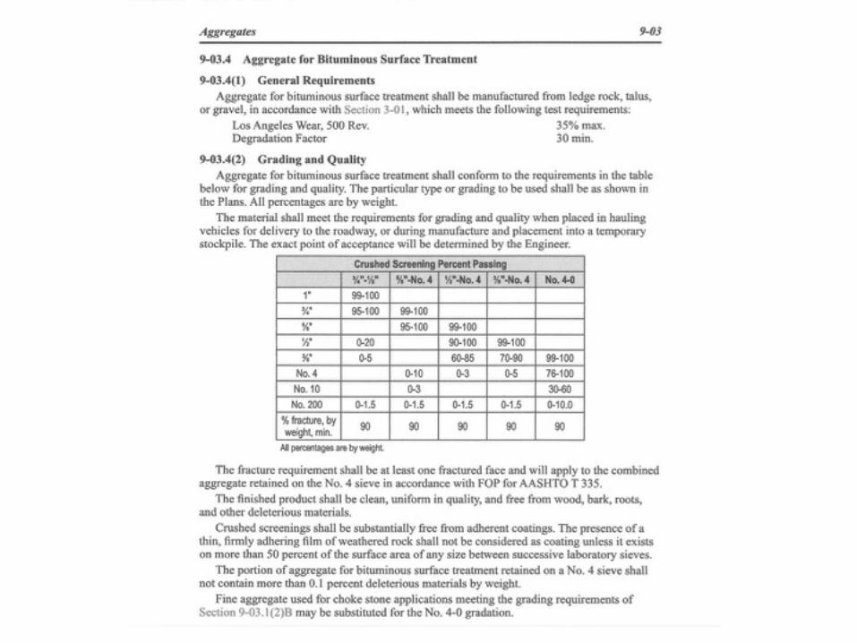
Aggregates
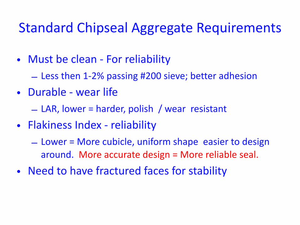
Standard Chipseal Aggregate Requirements
• Must be clean -‐ For reliability – Less then 1-‐2% passing #200 sieve; better adhesion
• Durable -‐ wear life – LAR, lower = harder, polish / wear resistant
• Flakiness Index -‐ reliability – Lower = More cubicle, uniform shape easier to design around. More accurate design = More reliable seal.
• Need to have fractured faces for stability

Aggregate Application Rate Calc• Need -‐ Ave least Dimension • Need -‐ Specific Gravity of the Aggregate • Calculate the Voids in Loose Agg
– V= (Loose unit weight (lbs/cubic ft)/(62.4*Spec Gravity)
• Wastage factor Example 10% for high traffic, 5% for very low slow traffic 1+.10 +1.1 high Traffic
• C (Appl Rate) = 46.8* (1-‐(0.4)*Voids in loose Agg*Ave Least Dimension*Specific Gravity *Wastage Factor for Traffic whip off
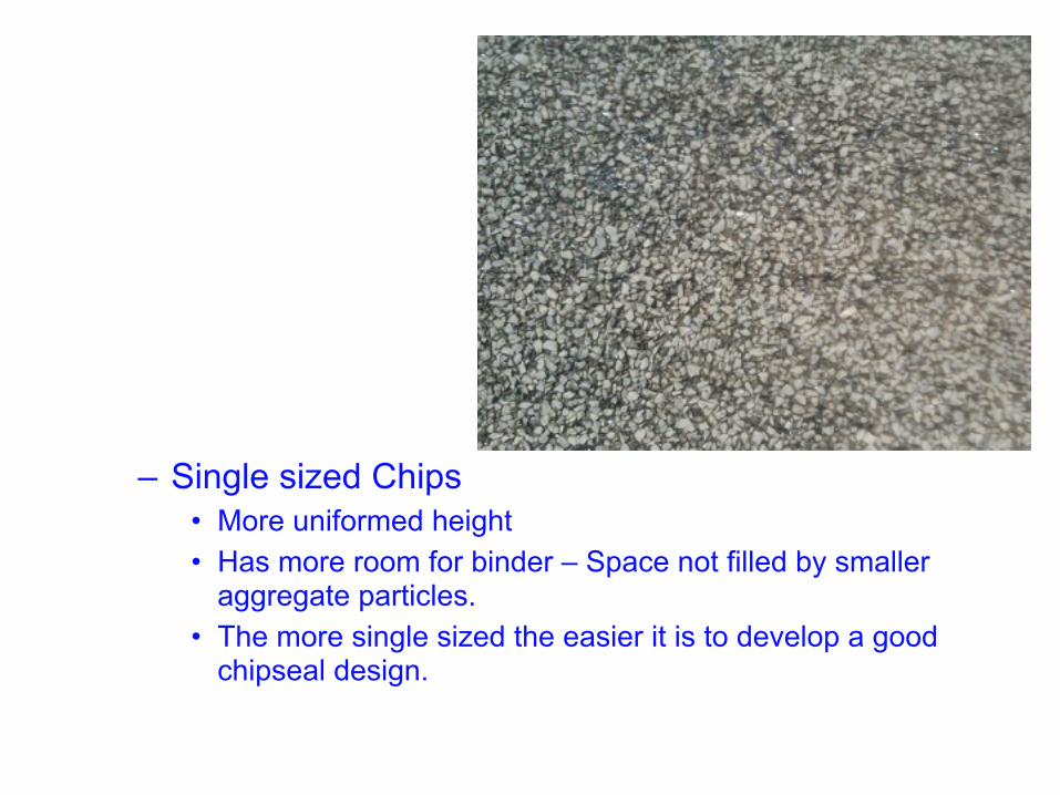
– Single sized Chips • More uniformed height • Has more room for binder – Space not filled by smaller
aggregate particles. • The more single sized the easier it is to develop a good
chipseal design.
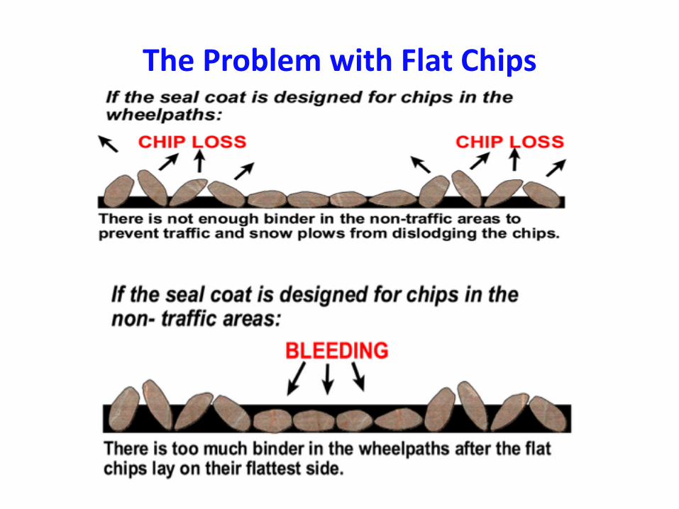
The Problem with Flat Chips
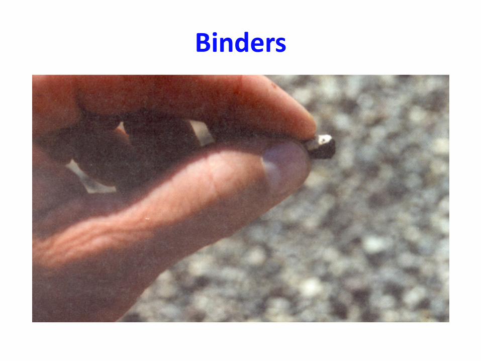
Binders

CRS-‐2P, CMS-‐2P
• Polymer Emulsions • Stiffer binder -‐ reduces bleeding • Develops strength faster than other emulsions, can sweep sooner.
• Requires clean chips • Must place chips immediately • Most Expensive conventional chipseal emulsion
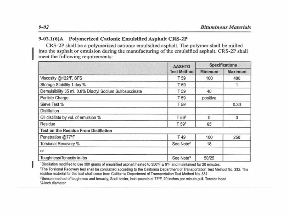
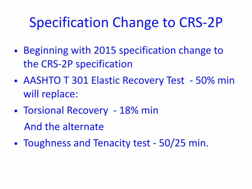
Specification Change to CRS-‐2P
• Beginning with 2015 specification change to the CRS-‐2P specification
• AASHTO T 301 Elastic Recovery Test -‐ 50% min will replace:
• Torsional Recovery -‐ 18% min And the alternate • Toughness and Tenacity test -‐ 50/25 min.
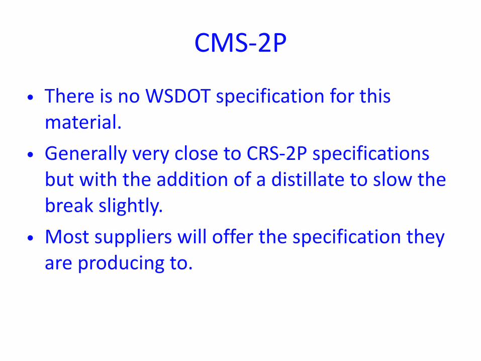
CMS-‐2P
• There is no WSDOT specification for this material.
• Generally very close to CRS-‐2P specifications but with the addition of a distillate to slow the break slightly.
• Most suppliers will offer the specification they are producing to.
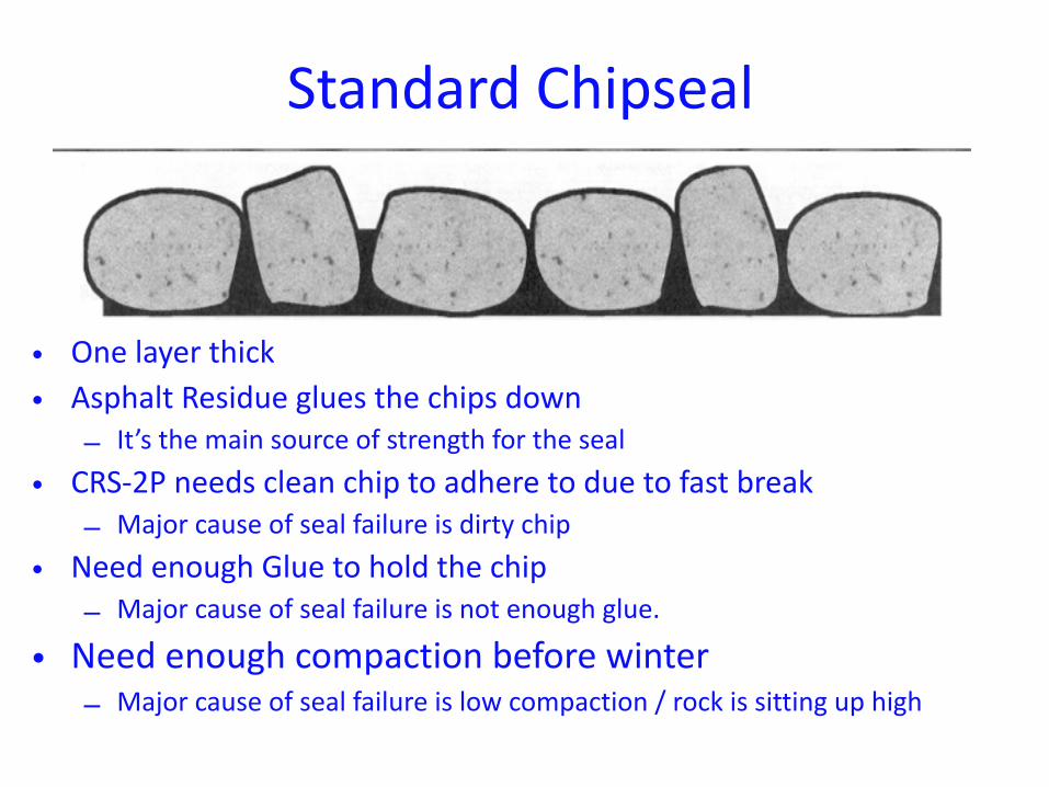
Standard Chipseal
• One layer thick • Asphalt Residue glues the chips down
– It’s the main source of strength for the seal • CRS-‐2P needs clean chip to adhere to due to fast break
– Major cause of seal failure is dirty chip • Need enough Glue to hold the chip
– Major cause of seal failure is not enough glue.
• Need enough compaction before winter – Major cause of seal failure is low compaction / rock is sitting up high
There is more to a successful Design than the numbers
• Timing: • 160 hours pavement temp exceeding 110 F
– The warmth is needed to soften the binder residue so that the final few percent of water that is trapped in the seal can work its way out
– This means even with a good design if the seal is done late in the season the final product will not be achieved until the next season.
– The earlier the better!! Let the warm weather help traffic finish the seal
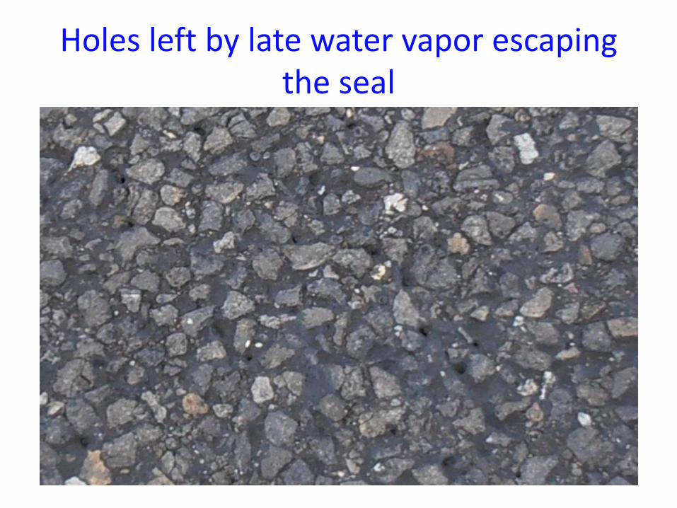
Holes left by late water vapor escaping the seal
There is more to a successful Design than the numbers
• When the rock is dropped into the binder the voids will approach 50%
• Rolling will drop that to around 30% • The final product to be achieved in the design will not occur until the voids are down around 20%
• If you don’t have enough traffic, the voids won’t decrease and the binder will not reach the design level. Possible seal failure until final embedment / voids are reached.
Need more rolling
• While the wheel paths get the compaction needed for a successful McLeod designed seal
• Parking lanes, Fog line, Turn lanes, Qtr Crown, Center Line area, etc. do not.
• Traffic will take much longer to give these areas the compaction needed per the design.
• Give it extra attention while building (Give them extra Rolling)
• Add a STEEL roller
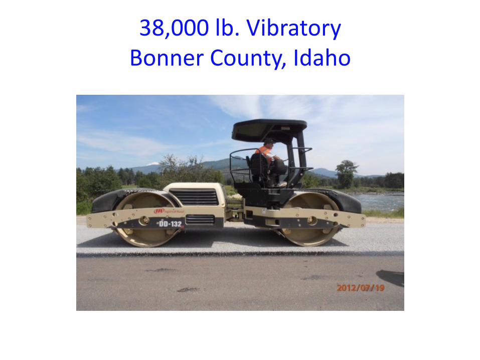
38,000 lb. VibratoryBonner County, Idaho
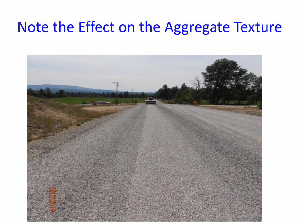
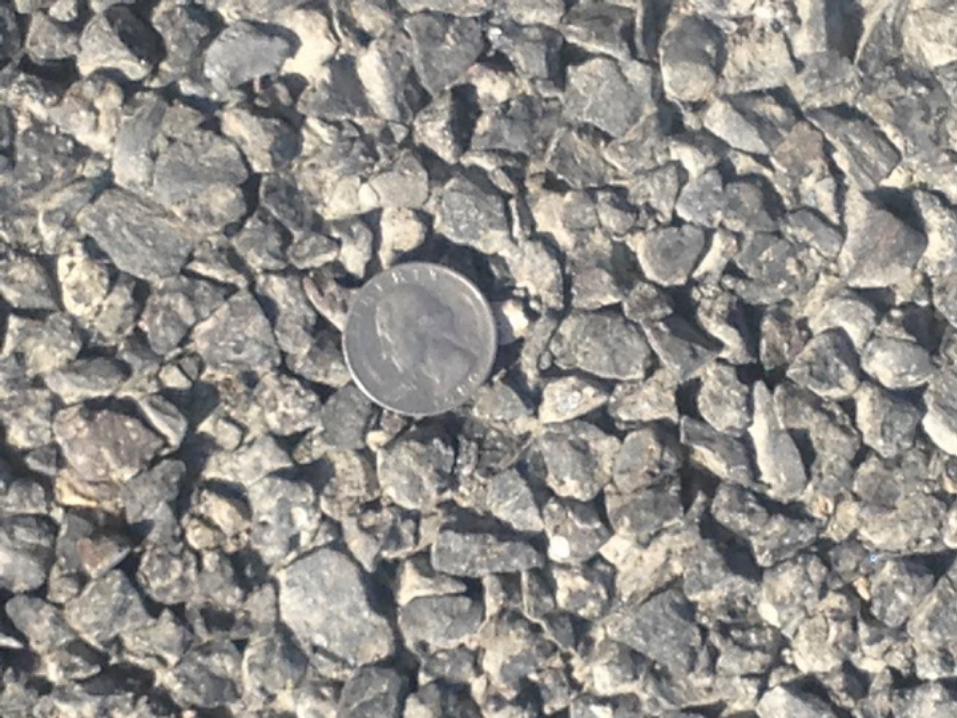
Note the Effect on the Aggregate Texture
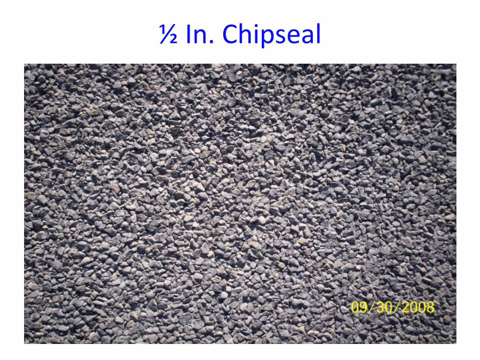
½ In. Chipseal
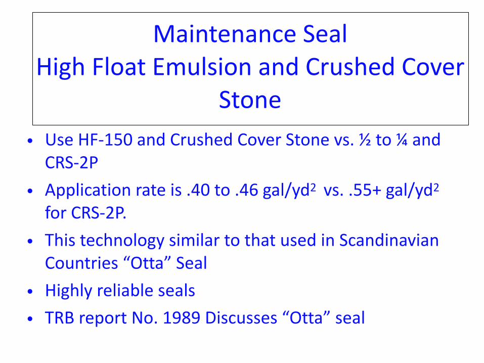
Maintenance Seal High Float Emulsion and Crushed Cover
Stone• Use HF-‐150 and Crushed Cover Stone vs. ½ to ¼ and CRS-‐2P
• Application rate is .40 to .46 gal/yd2 vs. .55+ gal/yd2 for CRS-‐2P.
• This technology similar to that used in Scandinavian Countries “Otta” Seal
• Highly reliable seals • TRB report No. 1989 Discusses “Otta” seal
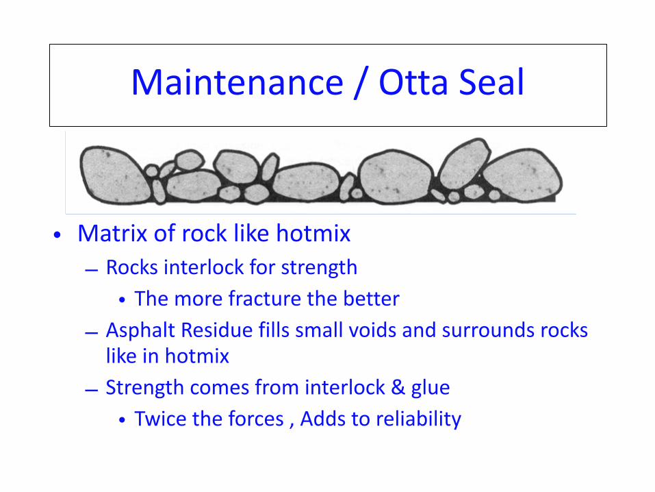
Maintenance / Otta Seal
• Matrix of rock like hotmix – Rocks interlock for strength
• The more fracture the better – Asphalt Residue fills small voids and surrounds rocks like in hotmix
– Strength comes from interlock & glue • Twice the forces , Adds to reliability
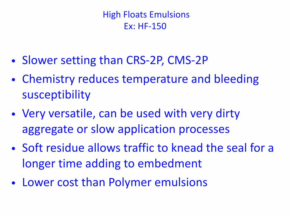
High Floats Emulsions Ex: HF-‐150
• Slower setting than CRS-‐2P, CMS-‐2P • Chemistry reduces temperature and bleeding susceptibility
• Very versatile, can be used with very dirty aggregate or slow application processes
• Soft residue allows traffic to knead the seal for a longer time adding to embedment
• Lower cost than Polymer emulsions
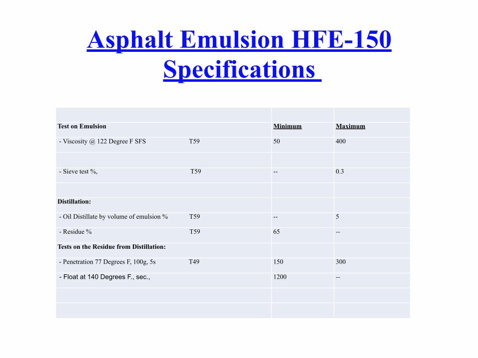
Asphalt Emulsion HFE-150 Specifications
Test on Emulsion Minimum Maximum
- Viscosity @ 122 Degree F SFS T59 50 400
- Sieve test %, T59 -- 0.3
Distillation:
- Oil Distillate by volume of emulsion % T59 -- 5
- Residue % T59 65 --
Tests on the Residue from Distillation:
- Penetration 77 Degrees F, 100g, 5s T49 150 300
- Float at 140 Degrees F., sec., 1200 --
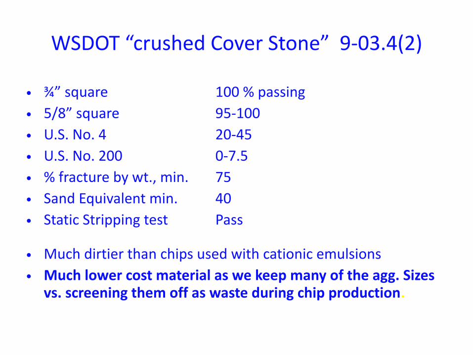
WSDOT “crushed Cover Stone” 9-‐03.4(2)
• ¾” square 100 % passing • 5/8” square 95-‐100 • U.S. No. 4 20-‐45 • U.S. No. 200 0-‐7.5 • % fracture by wt., min. 75 • Sand Equivalent min. 40 • Static Stripping test Pass
• Much dirtier than chips used with cationic emulsions • Much lower cost material as we keep many of the agg. Sizes
vs. screening them off as waste during chip production.
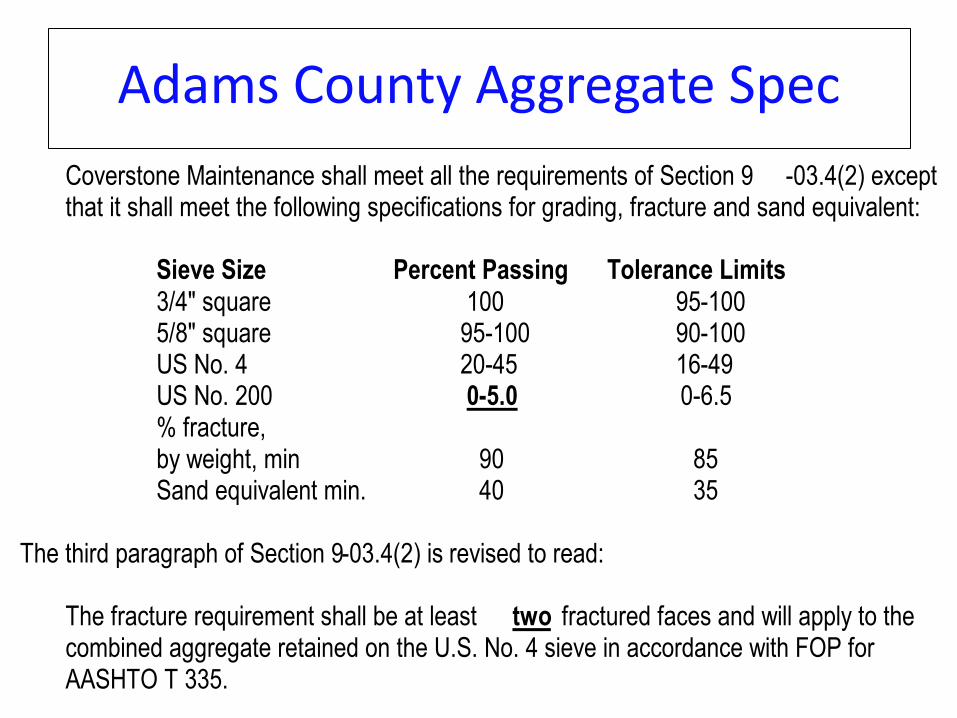
Adams County Aggregate SpecCoverstone Maintenance shall meet all the requirements of Section 9 -03.4(2) except 1 that it shall meet the following specifications for grading, fracture and sand equivalent: 2
3 Sieve Size Percent Passing Tolerance Limits 4 3/4" square 100 95-100 5 5/8" square 95-100 90-100 6 US No. 4 20-45 16-49 7 US No. 200 0-5.0 0-6.5 8 % fracture, 9 by weight, min 90 85 10 Sand equivalent min. 40 35 11
12 The third paragraph of Section 9-03.4(2) is revised to read: 13 14
The fracture requirement shall be at least two fractured faces and will apply to the 15 combined aggregate retained on the U.S. No. 4 sieve in accordance with FOP for 16 AASHTO T 335. 17
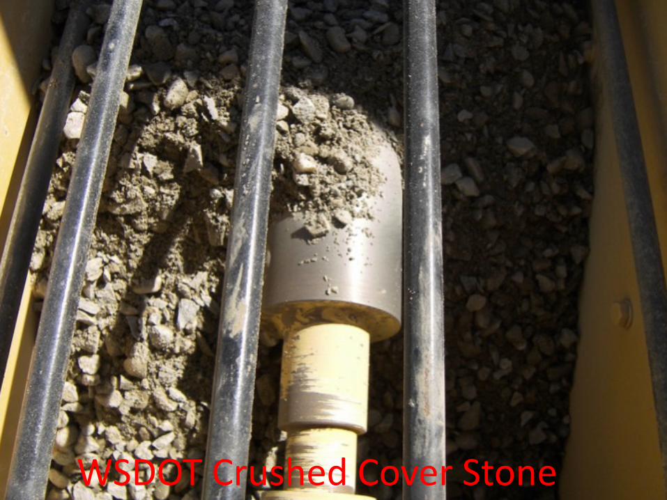
WSDOT Crushed Cover Stone
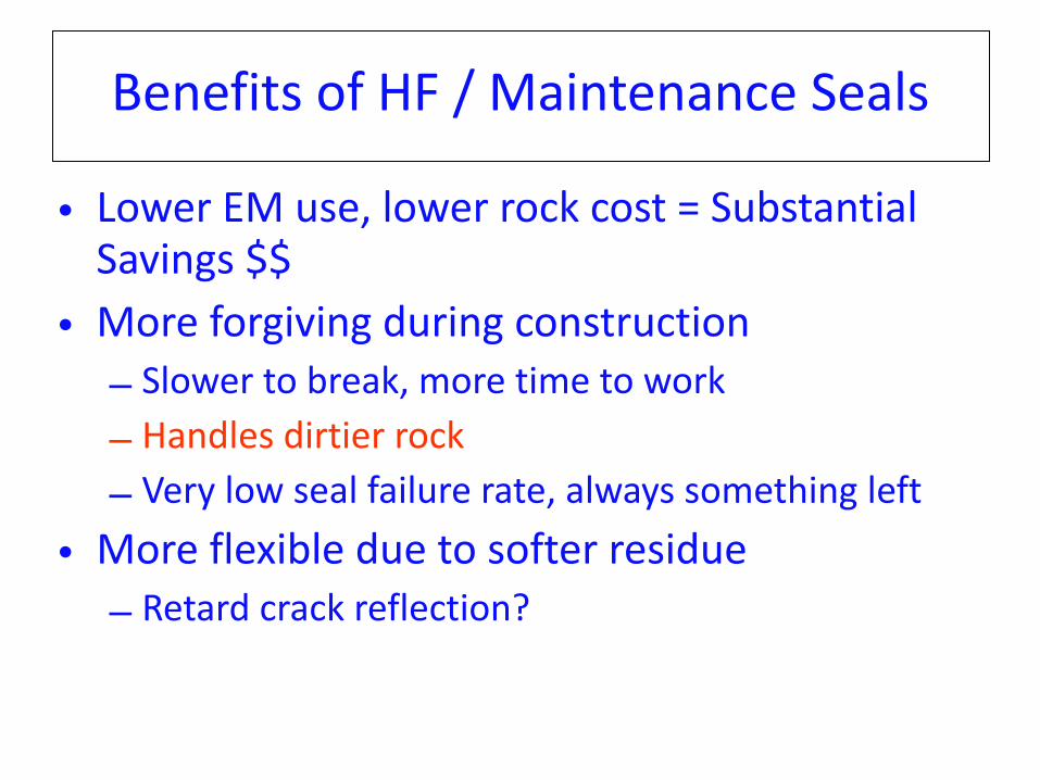
Benefits of HF / Maintenance Seals
• Lower EM use, lower rock cost = Substantial Savings $$
• More forgiving during construction – Slower to break, more time to work – Handles dirtier rock – Very low seal failure rate, always something left
• More flexible due to softer residue – Retard crack reflection?
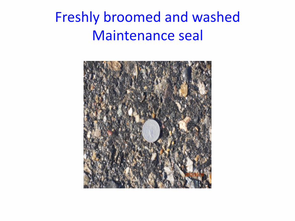
Freshly broomed and washed Maintenance seal
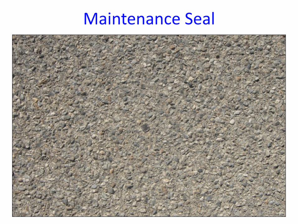
Maintenance Seal
Tips for Successful Maintenance Seals
• Maintenance Seals create a matrix much like hotmix – Treat them like hotmix – Higher traffic designs need to be compacted more
• Need to increase compaction while the emulsion is still wet and can grab loose rock. – Increased rolling effort means more compaction early, grabs rock before it can slough off.
• Increases thickness of seal (holding more rock) at equivalent emulsion rate.
Tips for Successful Maintenance Seals
• Water can be sprayed over the seal surface while rolling to help emulsion travel through the aggregate and expand coated surfaces.
• Higher traffic = more compaction, less room for asphalt residue. ( Just like Hotmix) – If you don’t compact enough during construction traffic will post compact and flush the surface just like under compacted hotmix.
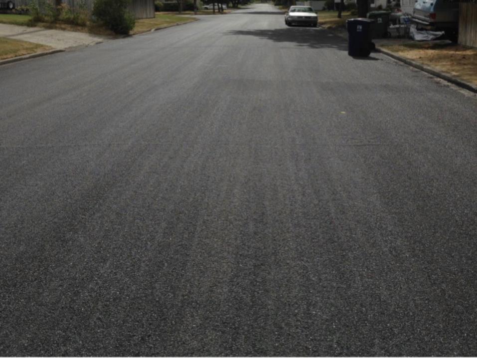
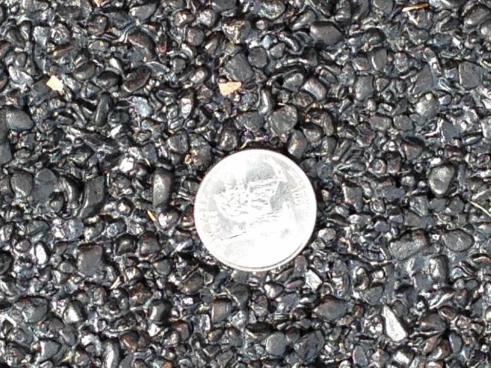
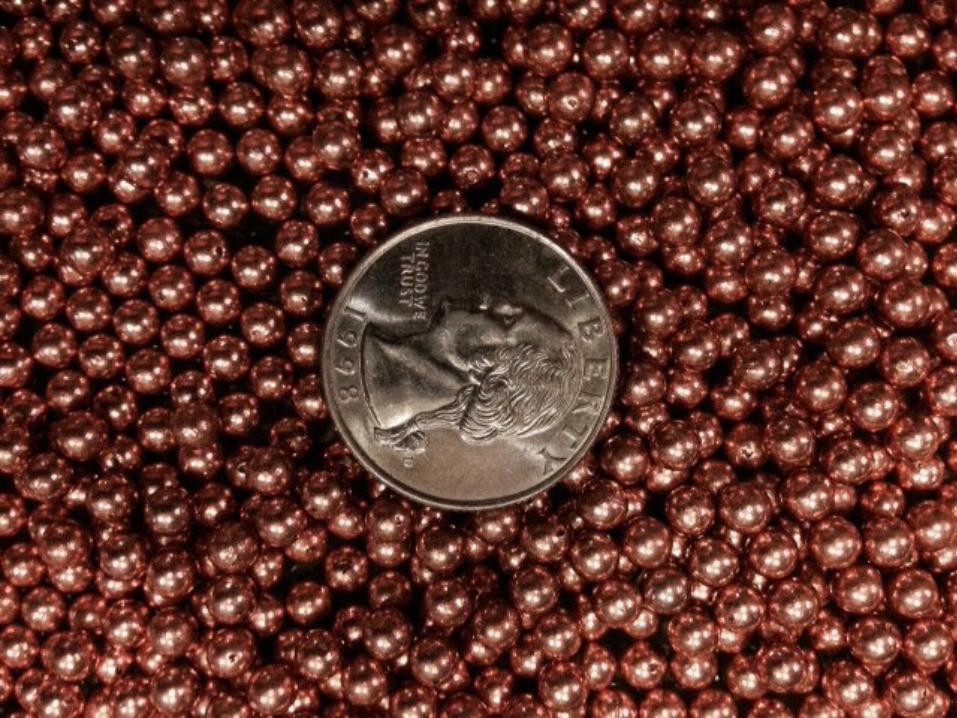
FA-‐2 Aggregate SealCity of Spokane
• Fine graded Seal using #4 Agg, CRS-‐2P and a post fog
• Provides fine surface for pedestrians and local traffic
• Seems tough – 3rd yr seals holding up very well • Aesthetically very appealing • Improves older surfaces much like slurry
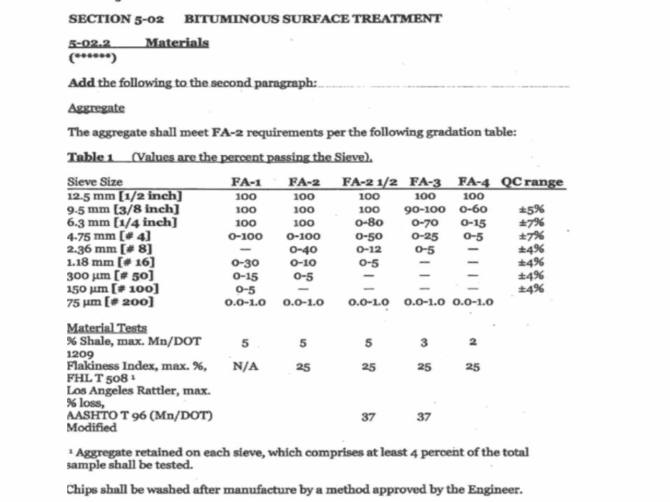
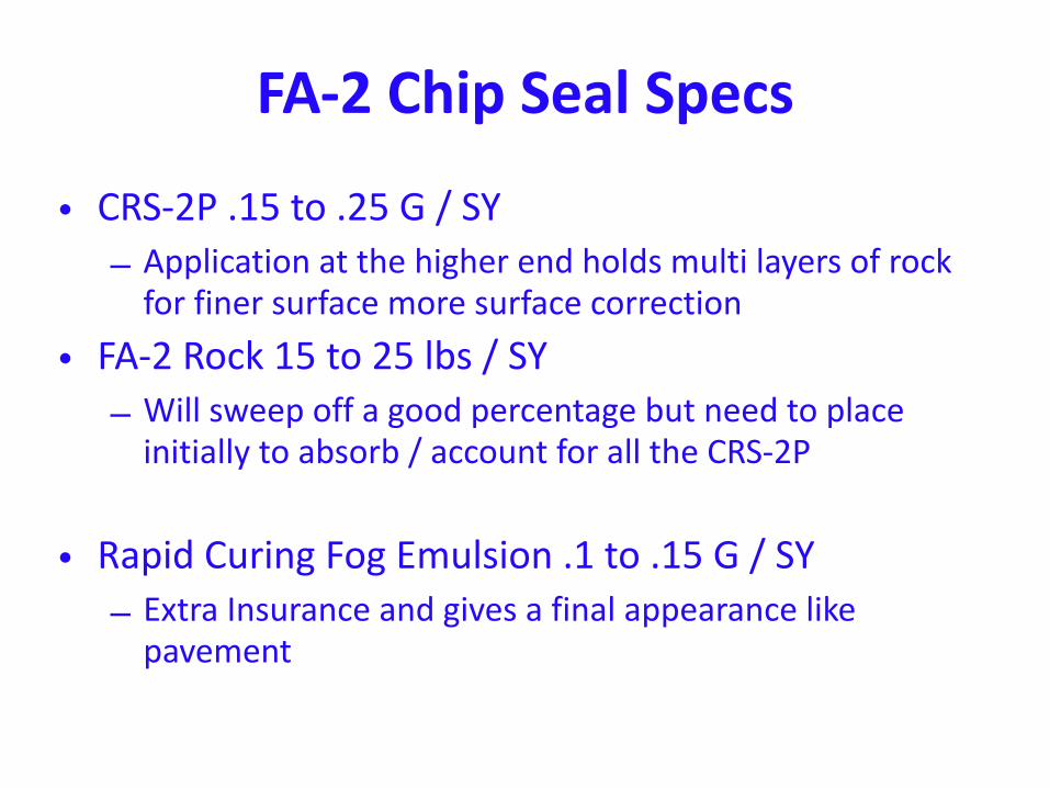
FA-‐2 Chip Seal Specs
• CRS-‐2P .15 to .25 G / SY – Application at the higher end holds multi layers of rock for finer surface more surface correction
• FA-‐2 Rock 15 to 25 lbs / SY – Will sweep off a good percentage but need to place initially to absorb / account for all the CRS-‐2P
• Rapid Curing Fog Emulsion .1 to .15 G / SY – Extra Insurance and gives a final appearance like pavement
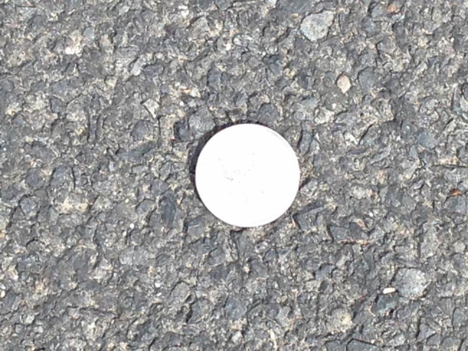
Issues with FA-‐2 Seals
• Finer seals show deformities more than larger seals – Need to not leave large bands of crackfiller they transfer through
– Drilling of the seal can be an issue with thicker emulsions, smaller rock and this high emulsion rate will show this more

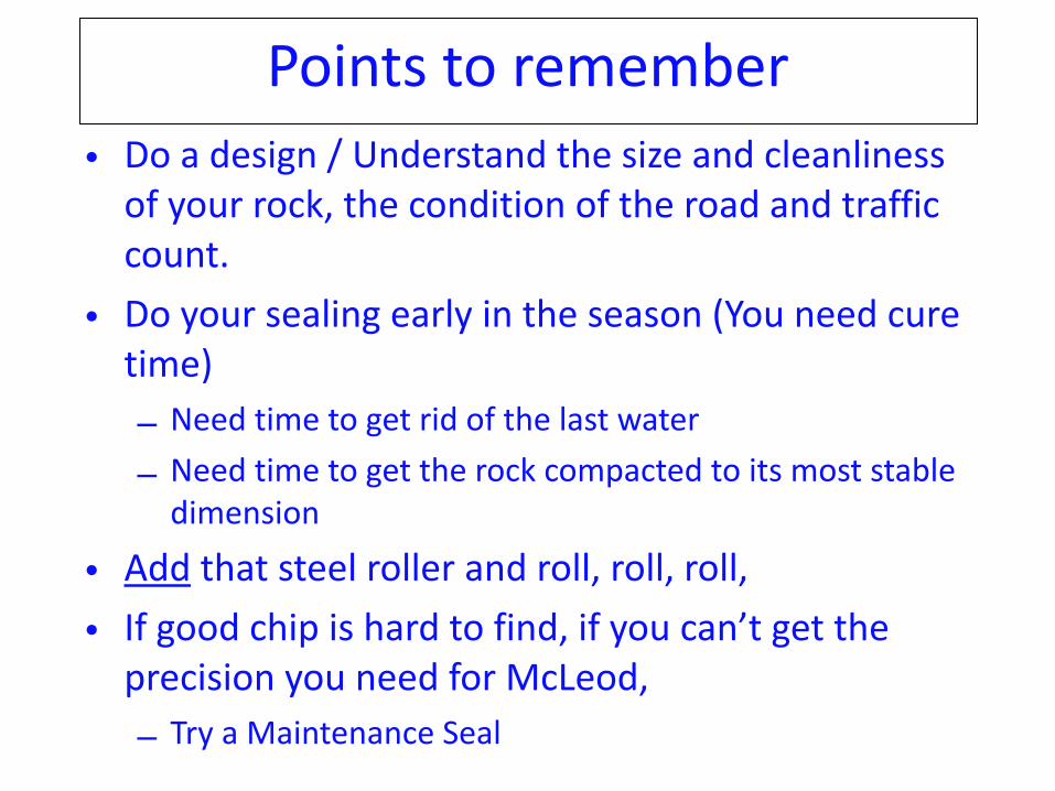
Points to remember• Do a design / Understand the size and cleanliness of your rock, the condition of the road and traffic count.
• Do your sealing early in the season (You need cure time) – Need time to get rid of the last water – Need time to get the rock compacted to its most stable dimension
• Add that steel roller and roll, roll, roll, • If good chip is hard to find, if you can’t get the precision you need for McLeod, – Try a Maintenance Seal


