DESIGNING CONFORMAL COOLING CHANNELS FOR TOOLING Xiaorong Xu, Emanuel Sachs, Samuel Allen, Michael Cima MIT Cambridge, MA 02139 Contact: Emanuel Sachs MIT (617) 253-5381 [email protected]77 Mass Ave Cambridge, MA 02139 Rtn 35-134 Abstract SFF technologies have demonstrated the potential to produce tooling with cooling channels which are conformal to the molding cavity. 3D Printed tools with conformal cooling channels have demonstrated simultaneous improvements in production rate and part quality as compared with conventional production tools. Conformal Cooling lines of high performance and high complexity can be created, thus presenting a challenge to the tooling designer. This paper presents a systematic, modular, approach to the design of conformal cooling channels. Recognizing that the cooling is local to the surface of the tool, the tool is divided up into geometric regions and a channel system is designed for each region. Each channel system is itself modeled as composed of cooling elements, typically the region spanned by two channels. Six criteria are applied including; a transient heat transfer condition which dictates a maximum distance from mold surface to cooling channel, considerations of pressure and temperature drop along the flow channel and considerations of strength of the mold. These criteria are treated as constraints and successful designs are sought which define windows bounded by these constraints. The methodology is demonstrated in application to a complex core and cavity for injection molding. 1. Introduction 1.1 Motivation The cooling of injection molding tooling is crucial to the performance of the tooling influencing both the rate of the process and the resulting quality of the parts produced. However, cooling line design and fabrication has been confined to relatively simple configurations primarily due to the limits of the fabrication methods used to make tools, but also due to the lack of a design methodology appropriate for cooling lines. 131
Transcript
DESIGNING CONFORMAL COOLING CHANNELS FOR TOOLING
Xiaorong Xu, Emanuel Sachs, Samuel Allen, Michael Cima
SFF technologies have demonstrated the potential to produce tooling with coolingchannels which are conformal to the molding cavity. 3D Printed tools with conformal coolingchannels have demonstrated simultaneous improvements in production rate and part quality ascompared with conventional production tools. Conformal Cooling lines of high performanceand high complexity can be created, thus presenting a challenge to the tooling designer. Thispaper presents a systematic, modular, approach to the design of conformal cooling channels.Recognizing that the cooling is local to the surface of the tool, the tool is divided up intogeometric regions and a channel system is designed for each region. Each channel system isitself modeled as composed of cooling elements, typically the region spanned by two channels.Six criteria are applied including; a transient heat transfer condition which dictates a maximumdistance from mold surface to cooling channel, considerations of pressure and temperature dropalong the flow channel and considerations of strength of the mold. These criteria are treated asconstraints and successful designs are sought which define windows bounded by theseconstraints. The methodology is demonstrated in application to a complex core and cavity forinjection molding.
1. Introduction
1.1 Motivation
The cooling of injection molding tooling is crucial to the performance of the toolinginfluencing both the rate of the process and the resulting quality of the parts produced. However,cooling line design and fabrication has been confined to relatively simple configurationsprimarily due to the limits of the fabrication methods used to make tools, but also due to the lackof a design methodology appropriate for cooling lines.
131
For many years mold designers have been struggling for the improvement of the coolingsystem performance, despite the fact that the cooling system complexity is physically limited bythe fabrication capability of the conventional tooling methods. Different methods such as thehelical channels, the baffled hole system, the spiral plug system and the heat-pipes have beendeveloped for the uniform and efficient cooling of the part (2). Some mold manufacturers such asInnova built tools with conformal cooling effect by stacking slices of the tool layer by layer withcooling channels milled on each layer. Other manufacturers such as CITO Products Inc.developed the pulse cooling technique for better control of the mold temperature in order toreduce the energy consumption and enhance uniform cooling condition.
The emergence of Solid Freeform Fabrication (SFF) processes offers injection moldmanufacturers new degrees of freedom in mold tooling. The SFF processes are additiveprocesses that construct 3D objects by incrementally building up cross sectional layers ofarbitrary complex shapes converted from CAD models. Typical SFF processes includestereolithography, selective laser sintering, three dimensional printing, solid ground curing,laminated object manufacturing, etc. [23]. The ability to fabricate 3D features with almostarbitrary complexity makes these processes extremely useful for fabricating parts and tools thatcannot be practically made by other techniques. One example of the applications is to fabricatecomplex cooling channels inside injection molds in order to improve the uniformity of cooling.The 3D Printing Lab at MIT has been participating in the injection molding tooling project forseveral years [24, 25, 26]. The industrial application of 3D Printed tools with serpentineconformal cooling channels built inside have achieved the simultaneous improvement of thecycle time by 15% and the part distortion by 9% [26]. With the manufacturing flexibility offeredby SFF processes such as 3D Printing, more complex cooling channel systems such as thatshown in Figure 1b can be fabricated for the further improvement of the cooling performance.
The emergence of new processes that can be used to create tools with conformal coolingchannels placed with almost arbitrary complexity not only offers the designer new degrees offreedom in the design of injection molding tools but also simplifies the methodology used todesign cooling channels. The work discussed in this paper seeks to develop a methodology forthe design of cooling channels that both simplifies the design and results in substantiallyimproved performance. As you will see from the paper this methodology makes the design ofcomplex cooling channel system for the inserts such as that shown in Figure 1b a handy work.
132
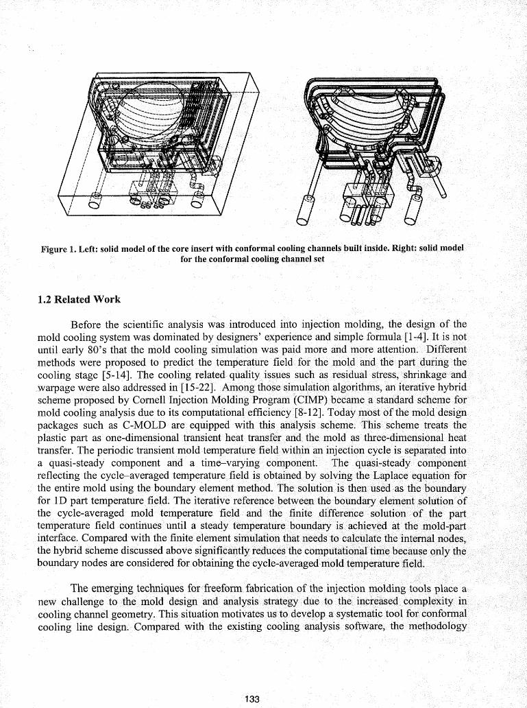
Figure 1. Left: solid model of the core insert with conformal cooling channels built inside. Right: solid modelfor the conformal cooling channel set
1.2 Related Work
Before the scientific analysis was introduced into injection molding, the design of themold cooling system was dominated by designers' experience and simple formula [1-4]. It is notuntil early 80's that the mold cooling simulation was paid more and more attention. Differentmethods were proposed to predict the temperature field for the mold and the part during thecooling stage [5-14]. The cooling related quality issues such as residual stress, shrinkage andwarpage were also addressed in [15-22]. Among those simulation algorithms, an iterative hybridscheme proposed by Cornell Injection Molding Program (CIMP) became a standard scheme formold cooling analysis due to its computational efficiency [8-12]. Today most of the mold designpackages such as C-MOLD are equipped with this analysis scheme. This scheme treats theplastic part as one-dimensional transient heat transfer and the mold as three-dimensional heattransfer. The periodic transient mold temperature field within an injection cycle is separated intoa quasi-steady component and a time-varying component. The quasi-steady componentreflecting the cycle-averaged temperature field is obtained by solving the Laplace equation forthe entire mold using the boundary element method. The solution is then used as the boundaryfor 1D part temperature field. The iterative reference between the boundary element solution ofthe cycle-averaged mold temperature field and the finite difference solution of the parttemperature field continues until a steady temperature boundary is achieved at the mold-partinterface. Compared with the finite element simulation that needs to calculate the internal nodes,the hybrid scheme discussed above significantly reduces the computational time because only theboundary nodes are considered for obtaining the cycle-averaged mold temperature field.
The emerging techniques for freeform fabrication of the injection molding tools place anew challenge to the mold design and analysis strategy due to the increased complexity incooling channel geometry. This situation motivates us to develop a systematic tool for conformalcooling line design. Compared with the existing cooling analysis software, the methodology
133
discussed ill this .paper builds .acisynthesis·tool instead of an analysis •• tool for the design of thecomplex conformal coolingcharuiels which take the full advantage ofSFF processes.
2. Heat transfer model for conformal cooling
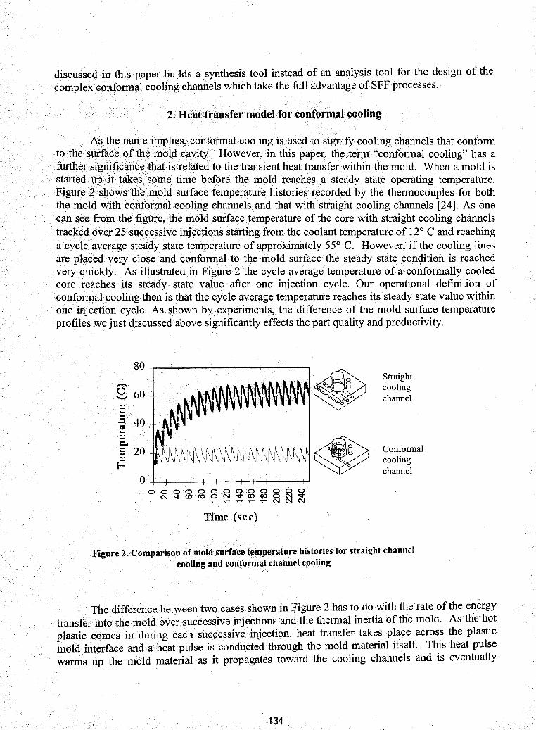
A.~the~a1t1eiITlPlies,¢onformalcoolingis usedto signify cooling channels that conformtoth~sllr~(lcYieft~~ meldigaXit;y. How~ver, in this paper,. th~ tel'fll"conformal cooling" has afurther/~~pn.ifjc(ll1~y~atis(r~lated to the transient heat transf~r within the mold. When a mold isstarted\1gitit~essoIl1etime .before the mold reaches •• a·steady state· operating temperature.Figure2s~owsthem91c1.surface temperatur~historiesrecorded by the thermocouples for boththemol4',Vith conf0srn-aLcooling channels and that with straight cooling channels [24]. As onecan see~omthefigllre,themold surface temperature of the core with straight cooling channelstrackYd.(ov~r25sucgessiveinjections startingfromthe coolant temperature of 12° C and reachinga cycle average steady state temperature of apgroximately 55° C. However, if the cooling linesare placedyery close.andconformaltothe. mold surface the steady state. condition is reachedvery quickly. As illustrated in Figure 2 the cycle. average temperature of aconformally cooledcore reaches its steady state value after one injection cycle. Our operational definition of90nfonnaLcooling then isthatthe cycle ayerage temperature reaches its steady state value withinone. inj~9tioncycle. As shown by experiments, the difference of the mold surface temperatureprofiles we just discussed above signifiCantly effects the part quality and productivity.
80 -.----'-- --.....- -----,
~O+--+-+-f-+-+-+-+-+-+-I-+---t-Joooooooooooog
N -.:t<O co 0 N -.:t.<o coo N "...-...-...-...-...-NNN
Time (sec)
Straightcoolingchannel
Conformalcoolingchannel
Figure 2. Comparison of mold surface temperature histories for straight channelcooling and conformal channel cooling
The.differencebetweentwo cases. shown in Figure 2 has to do with the.rate of the energytransfetiintothemoldover su~cessivei~j~:tions and the thermal inertia of the mold. As the hot.plasticieomesin during each sU9cessiv~injection, heat transfer take~ p~a~e acros~ the plasticll10ldinterface and a heat pulse is condu.cted through the mold matenalltself. ThIS heat pulsewarms up the mold Il1aterial as it propagates toward the. cooling channels and is eventually
134
removed in the cooling water. If the cooling channels are far from the mold's surface, successiveheat pulses keep raising the temperature of the rnolduntil the heat. pulse propagating in isbalanced by heat extraction by the coolant. Ifthe. cooling channels are close to tbemold surface,the effective thermal mass of the tool is confined to thatregion<between< the surface and thecooling channels and is much reduced. In addition, the conduction path from the surface ofthetools to the cooling lines is reduced. As a result, the steady state condition is reached much morerapidly and can inTact be attained within one injection cycle.
An energy balance may be written for the active portion of the mold, that is the portionbetween the surface and the cooling lines. Equation (1) shows the resulting differential equation(see Appendix A for derivation of this equation).
C I dTm + hrcDKm (T -T)Pm m m dt 2KmW + hrcDlm m c
P pCpIp (Tme1t Te.iect)
t cycle(1)
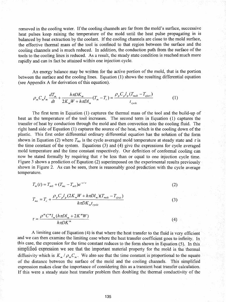
The first term in Equation (1) captures the thermal mass of the tool and the build-up ofheat as the temperature of the tool increases. The second term in Equation (1) captures thetransfer of heat by conduction through the mold and then convection into the cooling fluid. Theright hand side of Equation (1) captures the source of the heat, which is the cooling down of theplastic. This first order differential ordinary differential. equation has the solution of the formshown in Equation (2) where Tms is the cycle averaged mold temperature at steady state and 1: isthe time constant of the system. Equations (3) and (4) give the expressions for cycle averagedmold temperature and the time constant respectively. Our definition of conformal cooling cannow be stated formally by requiring that 1: be less than or equal to one injection cycle time.Figure 3 shows a prediction of Equation (2) superimposed onthe experimental results previouslyshown in Figure 2. As can be seen, there is reasonably good prediction with the cycle averagetemperature.
(2)
(3)
(4)
A limiting case of Equation (4) is that where the heat transfer to the fluid is very efficientand we can then examine the limiting case where the heattransfer coefficient goes to infiliity.Inthis case, the expression for the time constant reduces tothe form showninEquation (5). Inthissimplified expression we see that the important material property for the mold is the thermal
diffusivity Which.is ·Km / PmCm. We also. see that the time constantjsproportionaltot~esqua~e
of the distance between the surface of the mold and the cooling channels. This. simplifiedexpression makes ciear the importance of consideringthisasatransientiheattransfer calculation.If this were a steady state heat transfer problem then doubling the thermal conductivity of the
135
mold would allow the channels to be placed twice as far away. However, as we can see fromEquation (5) if we double the thermal conductivity and place the channels twice as far away thetime constant in fact increases by a factor of 2. Thus, while the material properties are important,the geometry (as seen by the square of the distance of Equation (5)) is even more important.
=PmCml~K m
25
(5)
20
',\ )'1 .''\ .\
:>". : I
I ,\ .\:
:\: , '. t, :'\),
)\ :' " ",. ., ol " " "I , ; , • J .' , ", .", \ , , : .~ I I \ \
~
" ; . • '" , I , .. \''.' .. . . ,. I, I \ , ". .~\ :~ \: I~,I
,.\; ~\' " \; ~
\, .'
.' .\ ,,' ',' \;I
_sirrulation data....... experimental data
Time [sec]
Figure 3. ComparisoDoftheexperimen(1atavs. the simulation data for themold surface temperature profile during successive. injections
3. Design methodology
The introduction of· conformal cooling significantly simplifies the .injection moldingcooling system design methodology. In theconfonnal cooling situation, the· heat transfer islocalized in a small region between. two adjacent cooling channels. This feature suggests that wefirst design a cooling "cell" composed ofthe small region between the adjacent cooling lines andthenmap the solution to the entire mold. The flexibility of SFF pro.cesses makes this modularapproach possible by minimizing the manufacturing constraint that must be applied. Thisstrategy simplifies the cooling line design by providing a sequential approach which provides aglobal solution by the addition of many local solutions.. While the design process is simplified,the resulting cooJing line designs can be quite complex and take full advantage of the flexibilityof SFFprocesses.
Figure 4 illustrates this design strategy by using a generic·part with a hemispherical domealld a flat bottom. AsSl10wn inthe figure, the. part is first divided into two cooling ZOl1eS (ahemisl'here<alld a flat.surface) based on its geometry. Then in each coolil1g zone the conformalcooling surface is const11lcted~ndthe cooling channel topological structure is defined. After thatthe system of cooling channels is further decomposed into small elements called cooling cells.
136
The heat transfer analysis and the cooling system design is based on these cooling cells and isthen mapped to the entire mold. This modularized design strategy is not sensitive to the partgeometry, therefore it keeps the same design simplicity no matter how complex the partgeometry is.
, back to mold
Contormalcooling
design rules
cavity
!0 0 00
oo
coolingpar
ICooling zone I
conformal
Original
\Cooling zol1e2
Cooling cell before Cooling cell after
Map designback to mold
Figure 4 Steps for the modularized cooling line design for a generic part
4. Design rules
After the cooling systemha.s pee~ .• dec0tnPosedjnto>simplecooliIlg cells .by the methoddiscussed above,. the design rules are applied. to these cooling cells .• in order toobt~ilJ.cooling
channel design parameters and process conditions. In thischapt~r, six.design·nl1esaryproposedand design windows.are constructed for the cooling line design based on individual cooling cells.These rules include design for conformaLcoolingcondition,<designJorcoolant pressure drop,design for. coolant temperature uniformity,designJor .sufficient .cooling, design for. uniformcooling and design for mold strength and deflection.
4;1 Design for conformal cooling condition
The conformal cooling condition defined in section 2 must be applied throughout thetooling in order to guarantee the good control of the temperature at the surface of the tool. Inorder to satisfy this condition, the mold designer can increase the heat transfer coefficient,increase the channel diameter, decrease the distance between the cooling lines and the mold wall
137
rmw645-staff
Stamp
or choos.e mold material with a high thermal diffusivity. The determination of these designparameters is also constrained by other design rules that will be discussed below.
4.2l)esigp for coolant pres~ured.rop
The allowable pressure drop of the coolant in the.conformal cooling channel isconstrained by the available pumping pressure of the chiller. The objective of the cooling linedesign for pressure drop is to Jind a proper colllbination ofthe coolant flow rate, the coolingchall11el dianletElr ap.gthecp()ling line length so that the resulting total pressure drop is smallerthan the given press.ure~udgElLThe fluid mechanics of the incompressible flow can be used topredict the coolant pressure drop that is a function of the cooling line length, the cooling linediameter and the coolant flow rate [27].
L 2P=-pv Cf2D
(6)
where Cf in Equation (6) is the cooling channel surface friction factor which differs for differentflow regions:
In the above equations, ReD is the Reynolds number of the coolant flow. e is the surfaceroughness of cooling channels.
4.3 Design for coolant temperature uniformity
The objective of the design for the coolant temperature uniformity is to check and makesure that the coolant temperature drop is maintained within a certain range. A simple expressionof the coolant temperature drop LIT is obtained by the following equation:
(9)
where lp is half the plastic part thickness, w is the cooling line pitch distance, L is the cooling linelength, Q is the coolant flow rate and tcycle is the injection cycle time. pc, Cc, PP' Cp are thedensities and specific heats for coolant and part materials respectively. Equation (9) indicatesthat during the steady injection cycles the heat pulse due to the cooling down of the plastic part istotally converted to the temperature rise of the coolant flow. In order to reduce the coolanttemperature drop, the designer can use the coolant with large thermal mass, increase the coolantflow rate, decrease the pitch distance between two adjacent cooling channels or reduce the lengthof the cooling line.
138
4.4 Design for sufficient cooling
As we have discussed in section 1, the cooling analysis scheme adopted by mostof molddesign software is computationally expensive and not good for the design and analysis ofcomplex cooling channels. With the concept of conformal· cooling, this scheme is muchsimplified. As the matter of fact, the steady cycle averaged mold temperature can be directlyderived from Equation (3). However, this expression requires both the part ejection temperatureTeject and the cycle time tcycle which can not be both obtained. A simple iteration discussed belowfinds the cycle time and the steady cyclic mold temperature T ms based on the required partejection temperature:
Step 1. Assume the cycle averaged mold temperature Tms.
Step 2. Calculate the cycle time tcycle for the required part ejection temperature according topart heat transfer.
Step 3. Calculate the part ejection temperature at the end oftcycle.
Step 4. Calculate the cycle averaged mold temperature Tms based on equation (3).Step 5. Replace Tmsin step 1 by the cycle averaged mold temperature value obtained instep 4.Step 6. Follow the iterations from step 1 to 5 until the cycle averaged mold temperature Tms
reaches a steady value.
For readers with special interest in detail algorithms, please refer to ApPcendix B.
4.5 Design for uniform cooling
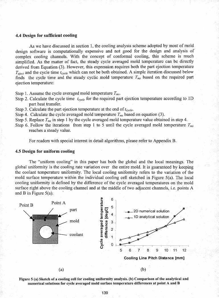
The "uniform cooling" in this paper has both the globaFand the JocaLmeanings. Theglobal uniformity is the cooling rate variation over the entire mold. It is guaranteed by/keepingthe coolant temperature uniformity. The local cooling uniformity refers to the variation. of themold surface temperature within the individual cooling cell sketched in Figure 5(a). The localcooling uniformity is defined by the difference of the cycle averaged temperatures onthe moldsurface right above the cooling channel and at the middle oftwo adjacent channels, i.e. points Aand B in Figure 5(a).
____ 2D numerical solution
1D analytical. solution
Point B Point A
part
mold
coolant
7 8 9 10 1 12
(a)
Cooling Line Pitch Distance [mm]
(b)
Figure 5 (~) Sketch of a cooling cell for·cooling uniformity analysis. (b) Comparison of the analytical andnumerical solutions·. for cycle aver~ged mold surface temperature differences at point A and B
139
The cycle averaged mold surface temperatures at point A and point B are expressed bythe following equations:
T + ppCplp{2KmW+htrDlb)(Tmelt -Tq~ect)
c h;r;DKmt cycle
(10)
(11)
where fa and harethe depth ofthe heat diffusion into the mold at point A and point B
r~spectively. Teject andTq~ectare part ejection temperatures at .A andB. respectively. The cycle
<iyeraged.temperatll,res Tma .and ··.Tmb are ··.obtained following •. the same routine as discussed insection 4.4. The lpcalcooling uniformity of the mold is thereby defined as the absolute value ofthe cycle averaged temperature difference between point A and point B:
(12)
Figure 5(b) plots the local cooling unifOrmity and compareihvith the numerical solution(see ApBel1dix .• C.Jor deta*) •for different cogling •line pitch distance. The material propertiesused for this calculation arethose.ofpplystyrene (part), 316 stainless steel (mold) and 30°Cwater(coolant). The ca1culatignis based on 2mmpart thickness,4rrun cooling channel diameterand 3mm vertical <iistance from cooling line to mold wall. The heat conduction distances la andlbin equation (19) and (20}>ary.ch()s~~tobedistancesfrom point A and B. to the wall of thecoolin? (channel respectively. As one can .see from the figure, the analytical and numericalsolutions match very well in a certain pitch distance range. More accurate prediction can beachieved by adding adjustment factorst? la and h,
4.6 Design for mold strength and deflection
R.ao [3] pred.icted the mold stress and delection based on the rectangll,lar cooling channelmodel shown in Figure 6. According to his model, the maximum tensile stress in the mold undera certain injection pressure Pm is:
0. 5PmD2O"max = 12
m
The maximum shear stress in the mold is:
0.75PmDTmax = I
m
The maximum :m.old surface deflection under pressurePm is:
(13)
(14)
(15)
The above expressions represent the worst case of the loading because the commonlyused cooling channels are circular shaped that result in much smaller stress and deflection. Thenumerical simulation shows that the stress concentration is reduced by over 50% if we choosechannels with round comers.
Injection pressure Pm
Mold
Mold surface profile underinjection pressure
Cooling channel
Figure 6 Sketch of a cooling ceHunder the injection pressure
5. Tool design and fabrication with conformal cooling channels
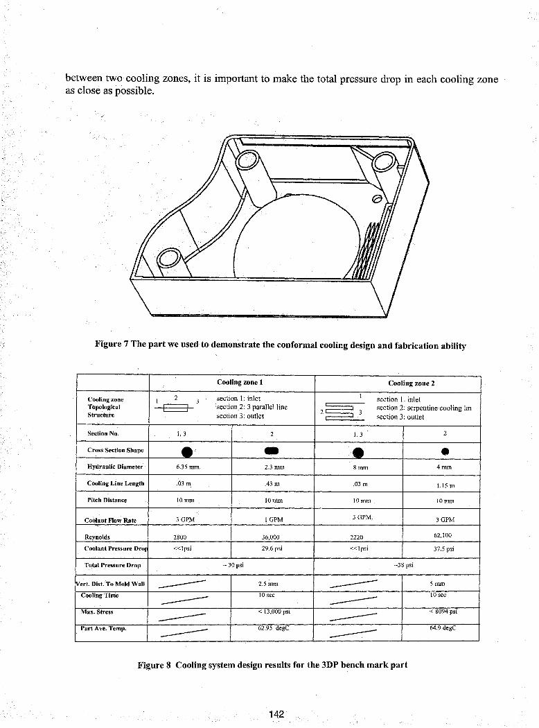
With the help of the .conformal cooling line design methodology, the 3D Printing Lab ofMIT has successfully designed and fabricated the. moldinserts for the part shown in Figure 7.The challenge placed by this p~t't is thatthe geometric features are so<small andsoclos~toeachother that it gives the designer little room for the cooling channel placement. In order to proceedthe conformal cooling line design for this part, we first divide the part into two cooling zones.For each cooling zone, the cooling line topological structureiisdefined and differentcoolingchannel cross section shapes are assigned to differenfsectionsofthe cooling line.. Then thecooling system is further decomposed into individual coollngcellsand the design rules areapplied to these cells to obtain the local solution of the cooling channel parameters. The 2Dnumerical simulation (see Appendix C for details) is also used for the evaluation of the transientheat transfer in each cooling cell..Figure 9 shows the design results for individuaLcooling cells.These results include the cooling channel geometry,processcondition aswellas the evaluationof design ruJes such as the part ejection temperature, the coolant pressure drop, the mold stress,etc. In addition to the local design of individual· cooling cells, the designer is responsible forcoordinating between local solutions for the •. properglobal •••perf0rtnan.c¢.0l1e~xa.t1lpleiiofsucllcoordination is to balance the. coolant flows .between coolingzgnes. In the table showninF;igure8.the coolantpressure.drops.for.eachse~tionofthecoolingzone are. summed uP.so that the totalpressure drop through each cooling zone .is obtained. In order to maintain the. equal coolant. flow
141
rmw645-staff
Stamp
between two cooling zones, it is important to make the total pressure drop in each cooling zoneas close as possible.
Figure 7 The part we used to demonstrate the conformal cooling design and fabrication ability
Cooling zone 1 Cooling zone 2
2 section I: inlet Isection I: inletCooling zone I 3
Topological rI section 2: 3 parallel line2~ section 2: serpentine cooling lin
Structure section 3: outlet3
section 3: outlet
Section No. 1,3 2 1,3 2
Cross Section Shape • - • •Hydraulic Diameter 6.35 mm 2.3mm 8 nun 4mm
Part Ave. Temp. ------ 62.95 degC ------ 64.9 degC
Figure 8 Cooling system design results for the 3DP bench mark part
142
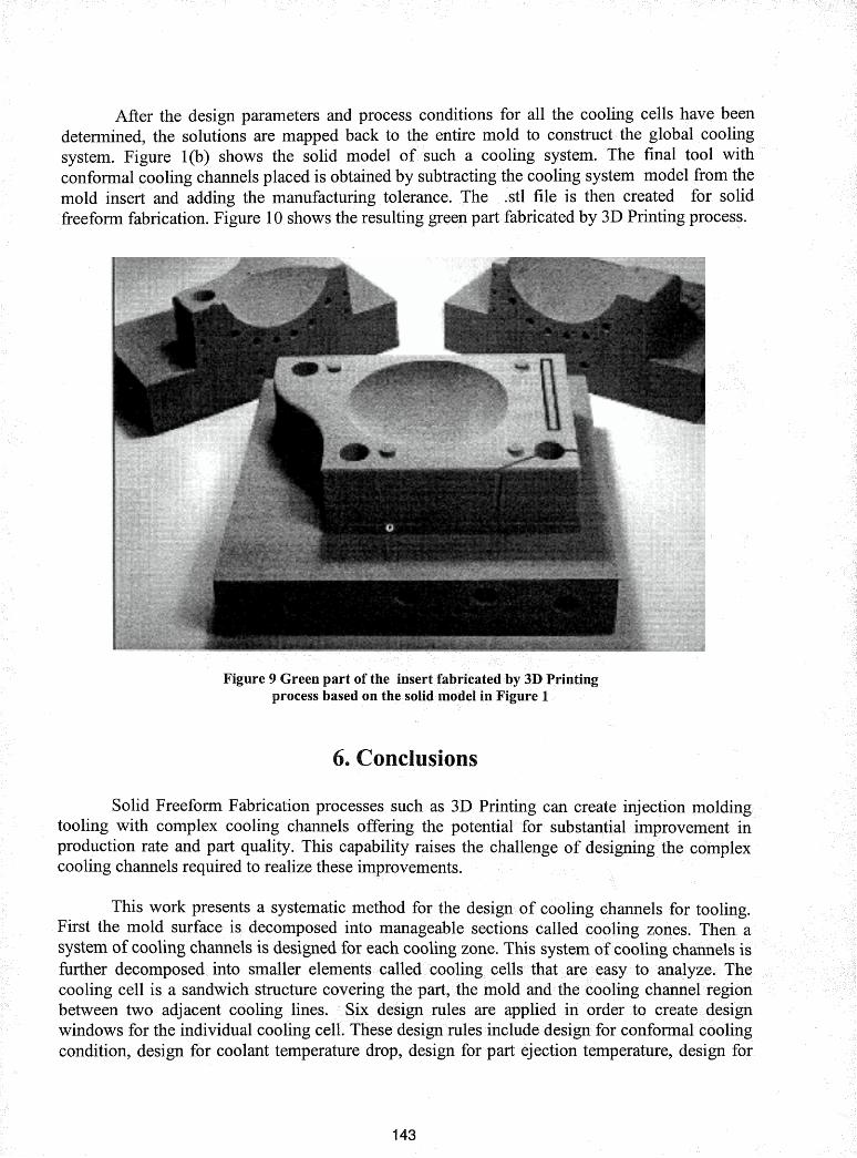
After the design parameters and process conditions for all the cooling cells have beendetermined, the solutions are mapped back to the entire mold to construct.· the global coolingsystem. Figure 1(b) shows the solid model ofsuch a cooling system. The final tool withconformal cooling channels placed is obtained by subtracting the cooling system model from themold insert and adding the manufacturing tolerance. The .stl file is then created for solidfreeform fabrication. Figure 10 shows the resulting green part fabricated by 3D Printing process.
Figure 9 Green part of theprocess based on
6. Conclusions
Solid Freeform Fabrication processes such as 3D Printing can create injection moldingtooling with complex cooling channels offering the potential for substantial improvement inproduction rate and part quality. This capability raises the.challenge of designing the cOmplexcooling channels required to realize these improvements.
This work presents a systematic method for the design of cooling channels for tooling.First the mold surface is. decomposed into manageable sections called cooling zones. Thensystem of cooling channels is designed for each cooling zone. This system ofcooling channels isfurther decomposed into smaller elements called. coolingi cells that are easy to analy*e. Thecooling cell is a sandwich. structure covering the part,the mold and·.the cooling channel regionbetween two adjacent cooling •lines. Sixdesign rules are applied in order to createidesignwindows for the individual cooling cell. These design rules include design for conformal coolingcondition, design for coolant temperature drop, design for part ejection temperature, design for
143
rmw645-staff
Stamp
sufficient cooling, design forffiold strength and deflection and design for cooling uniformity.After the design for individual cooling cell is fillished, the solution is mapped back to themold inorder to build the entire conformal cooling sY$tem.
7.J\ckno'Nledg~ent
The work discussed in this paper is supported by the Technology Re-Investment Project,Cooperative Agreement (DMI - 9420964) funded by DARPA and administered by NSF, and the3D Printing Industrial Consortium. The authors thank members of3DP Consortium and thecolleagues of 3DP Lab for their consistent support and encouragement. Special thanks are due toDick Barlik from Hasbro, who designed the prototype part for the 3DP benchmark tool, DavidBrancazio and Jim Serdy from 3D Printing Lab ofMIT, who took care of most of the work fromadministration to manufacturing of the conformal cooling project, Dr. K. K. Wang and Dr.Hieber from Cornell Injection Molding Program, who provided generous help andencouragement in mold cooling system design and simulation.
8. Nomenclature
pm, PP' pc :Cm, Cp , Cc:Km ,Kp ,Kc :
am, ap, ac:
pc :ReD:Q:v:he:e:CfT melt:
Teject:
T~:
T~:
Tc:
1m:
1p:D:w:L:Em:Om:Lim:Lip:Lit:
Density of the mold, the plastic part and the coolantSpecific heat ofthe mold, the plastic part and the coolantThermal conductivity of the mold, the plastic part and the coolantThermal diffusion of the mold, the plastic and the coolantCoolant viscosityCoolant Reynolds numberCoolant flow rateCoolant flow velocityHeat transfer coefficient between mold and coolantCooling channel surface roughnessCooling channel surface friction factorPlastic melt processing temperaturePlastic ejection temperature
Cycle averaged mold temperature at steady operation
Cycle averaged mold temperature as a function of time
Cycle averaged mold temperature
Coolant temperatureVertical distance from cooling line to mold wallHalf the plastic part thicknessCooling channel diameterCooling line pitch distanceCooling line lengthYoung's modulus of the moldShear modulus of the moldStep length of finite difference nodes for the moldStep length of finite difference nodes for the partStep length for the simulation time
144
tcycle: Injection cycle timeT: mold time constant
9. Reference
1. Z. Tadmore, C. Gogos, "Principles of Polymer Processing", Wiley, 1979, p584 - 610R. Pye, "Injection mould design", Longman, 1989
3. N. Rao, "Design formulas for plastics engineers", Hanser, 1991, chapter 64. D. Rosato, "Injection Mold Design Handbook", Van Hostrand Reinhold Comp., NY, 1985,
Chapter 7, P160 - 2345. K. Singh, "Design of Mold Cooling System", Injection and Compression Molding
Fundamentals, A. Isayev Ed., Marcel Dekker, 1991, p567 - 6056. C. Austin, "Mold cooling", ANTEC {85, p764 - 7687. Chu, M. Kamal, S. Goyal, "A Computer Simulation of the Injection Molding Process
Including Filling, Packing and Solidificatioh", ANTEC'89, p344 - 3478. T. Kwon, "Application of the Boundary Integral Method to the Nonisothermal Flow of a
Polymeric Fluid Advancing in a Thin Cavity of Arbitary Shape", CIMP Technical Report,No. 38 Jan-82
9. T. Kwon, "Mold Cooling System Design Using Boundary Element Method", ASME JournalofEng. for Industry, Vol. 110, p384 - 394
10. L. Tumg, "Application of the Boundary Element Method to the Cooling-Line Design forInjection Mold.s", CIMP Technical Report, No. 56, Jan-87
11. L. Tumg, K. Wang, "A computer - aided cooling line design system for injection molds",Journal ofengineeringfor industry, vol 112, May-90, p161
12. K. Himasekhar, J. Lottey, K. Wang, "CAE of Mold Cooling in Injection Molding Using aThree Dimensional Numerical Simulation", Journal of Engineering for Industry, vol. 114,May-92, p213 - 221
13. S. Chen, S. Yu, A. Davidoff, "Hybrid Mehods for Injection Mold Cooling ProcessSimulation and Mold Cooling System Analysis", ANTEC'91, p499 - 503
14. S. Hu, N. Cheng, S. Chen, "Effect of Cooling System Design and Process Parameters onCyclic Variation of Mold Temperatures - Simulation by DRBEM", Plastics, Rubber andComposites Processing and Applications, Vol. 23, No.4, 1995, p221 - 231
15. M. Rezayat, T. Burton, "Combined Boundary-Element and Finite - Difference Simulation ofCooling and Solidification in Injection Molding",
16. Y. Lauze, J. Hetu, "Temperature Prediction of Part and Mold Using Finite ElementSimulations", ANTEC'94, p809 - 812
17. M. Rezayat, "Numerical Computation of Cooling-Induced Residual Stress and DeformedShape for Injection-Molded Thermoplastics", ANTEC'89, p341 - 343
18. R. Thomas, N. McCaffery, "The Prediction of Real Product Shrinkage Calculated from aSimulation fo the Injection Molding Process", ANTEC'89, p371 - 375
19. S. Chen, N. Cheng, K. Jeng, "Post-Filling Simulation and Analyses of Shrinkage andWarpage of the Injection Molded Parts", ANTEC'91 , p493 - 498
20. G. Titomanlio, K.. Jansen, "In-Mold Shrinkage and Stress Prediction in Injection Molding",Polymer Engineering and Science, Vol. 36, No. 15, A.ug-96, p2041 - 2049
145
21. S. Liu, "Modeling and Simulation of Thermally Induced Stress and Warpage in InjectionMolded Thermoplastics", Polymer Engineering and Science, Vol. 36, No.6, Mar-96, p807 818
Products", Polymer Engineering and Science, Vol. 36, No. 14, Jul-96, p1886 - 189623. H.L.Mal."cus, D. L. Bourell, "Solid Freeform Fabrication Finds. New Applications",
tooling and prototypes directly from <a CAD model", Transactions of the ASME: Journal ofEngineeringforlndustry, vol 114, no.4, Nov -1992, p481 - 488
25. E.Sachs, E. Wylonis, M. Cima,S. Allen,S. Micheals, E. Sun, H. Tang, H. Guo, "InjectionMolding Tooling by Three Dimensional Printing: a Desktop Manufacturing Process",ANTEC'95
26.E. Sachs, S. Allen, H. Guo, LBanos,M.Cima, J. Serdy, D.Brancazio, "Progress on Toolingby 3D Printing: Conformal Cooling, DimensionaL Control, Surface Finish and Hardness",Solid Freeform Fabrication Proceedings, Sept-1997, p115-123
27. J. Fay, Introduction to Fluid Mechanics, MIT Press, 199528. Mills, Heat and Mass Transfer, Irwin Press, Chicago, 1995