Brigham Young University Brigham Young University BYU ScholarsArchive BYU ScholarsArchive Theses and Dissertations 2020-12-08 Effects of Conformal Cooling Channels on Additively Effects of Conformal Cooling Channels on Additively Manufactured Injection Molding Tooling Manufactured Injection Molding Tooling Tyler Blaine Whatcott Brigham Young University Follow this and additional works at: https://scholarsarchive.byu.edu/etd Part of the Engineering Commons BYU ScholarsArchive Citation BYU ScholarsArchive Citation Whatcott, Tyler Blaine, "Effects of Conformal Cooling Channels on Additively Manufactured Injection Molding Tooling" (2020). Theses and Dissertations. 8727. https://scholarsarchive.byu.edu/etd/8727 This Thesis is brought to you for free and open access by BYU ScholarsArchive. It has been accepted for inclusion in Theses and Dissertations by an authorized administrator of BYU ScholarsArchive. For more information, please contact [email protected], [email protected].
Transcript
Brigham Young University Brigham Young University
BYU ScholarsArchive BYU ScholarsArchive
Theses and Dissertations
2020-12-08
Effects of Conformal Cooling Channels on Additively Effects of Conformal Cooling Channels on Additively
Follow this and additional works at: https://scholarsarchive.byu.edu/etd
Part of the Engineering Commons
BYU ScholarsArchive Citation BYU ScholarsArchive Citation Whatcott, Tyler Blaine, "Effects of Conformal Cooling Channels on Additively Manufactured Injection Molding Tooling" (2020). Theses and Dissertations. 8727. https://scholarsarchive.byu.edu/etd/8727
This Thesis is brought to you for free and open access by BYU ScholarsArchive. It has been accepted for inclusion in Theses and Dissertations by an authorized administrator of BYU ScholarsArchive. For more information, please contact [email protected], [email protected].
Effects of Conformal Cooling Channels on Additively Manufactured Injection Molding Tooling
Tyler Blaine Whatcott Department of Manufacturing Engineering, BYU
Master of Science
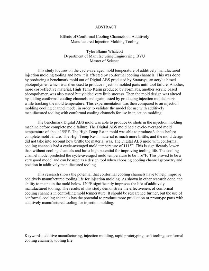
This study focuses on the cycle-averaged mold temperature of additively manufactured injection molding tooling and how it is affected by conformal cooling channels. This was done by producing a benchmark mold out of Digital ABS produced by Stratasys, an acrylic based photopolymer, which was then used to produce injection molded parts until tool failure. Another, more cost-effective material, High Temp Resin produced by Formlabs, another acrylic based photopolymer, was also tested but yielded very little success. Then the mold design was altered by adding conformal cooling channels and again tested by producing injection molded parts while tracking the mold temperature. This experimentation was then compared to an injection molding cooling channel model in order to validate the model for use with additively manufactured tooling with conformal cooling channels for use in injection molding.
The benchmark Digital ABS mold was able to produce 66 shots in the injection molding machine before complete mold failure. The Digital ABS mold had a cycle-averaged mold temperature of about 155°F. The High Temp Resin mold was able to produce 3 shots before complete mold failure. The High Temp Resin material is much more brittle, and the mold design did not take into account how brittle the material was. The Digital ABS mold with conformal cooling channels had a cycle-averaged mold temperature of 111°F. This is significantly lower than without cooling channels and has a high potential for improving tooling life. The cooling channel model predicted the cycle-averaged mold temperature to be 116°F. This proved to be a very good model and can be used as a design tool when choosing cooling channel geometry and position in additively manufactured tooling.
This research shows the potential that conformal cooling channels have to help improve additively manufactured tooling life for injection molding. As shown in other research done, the ability to maintain the mold below 120°F significantly improves the life of additively manufactured tooling. The results of this study demonstrate the effectiveness of conformal cooling channels in controlling mold temperature. It should be researched further, but the use of conformal cooling channels has the potential to produce more production or prototype parts with additively manufactured tooling for injection molding.
In order to help protect the inserts from the brunt of the clamping force of the injection
molding machine and to have a way to mount the inserts, support tooling frames were designed
and built. The design was very simple. The A-side was made to fit on the injection molding
machine that was used, a BOY 22-A. The B-side was made to fit in a standard M.U.D. base (see
Figures 3-8 and 3-9). The frames were made out of 6061 aluminum for its high machinability.
The frames were then altered after the benchmark mold was tested to accommodate for the
cooling channels and to provide a different mounting system for the inserts with conformal
cooling channels.
Figure 3-8: Benchmark Mold Setup
.
Figure 3-9: Cooling Line Alterations
23
Mold Production and Preparation
The benchmark molds were printed in 2 different materials, both the Digital ABS from
Stratasys and the High Temp Resin from Formlabs. The Digital ABS material specifically was a
combination of the materials RGD 515 and RGD 531 to produce the ivory color Digital ABS.
Support material used for the Stratasys print was SUP 705. The Digital ABS mold was printed
on an Objet polymer jetting system. The High Temp Resin specifically was FLHTAM02 from
Formlabs. The High Temp Resin mold was printed on a Form 2 SLA system.
The Stratasys mold was produced first as the benchmark mold for all tests conducted, it
being the most commonly studied material for this application. The mold was prepped by
removing the support material using a waterjet and some light sanding. After the support
material was removed, holes were drilled in the mold for mounting them to the support frames.
In order to install the sprue bushing, some sanding was required on the inside of the mold to
allow for a proper fit. After some initial trials to ensure proper function of the mold, a design
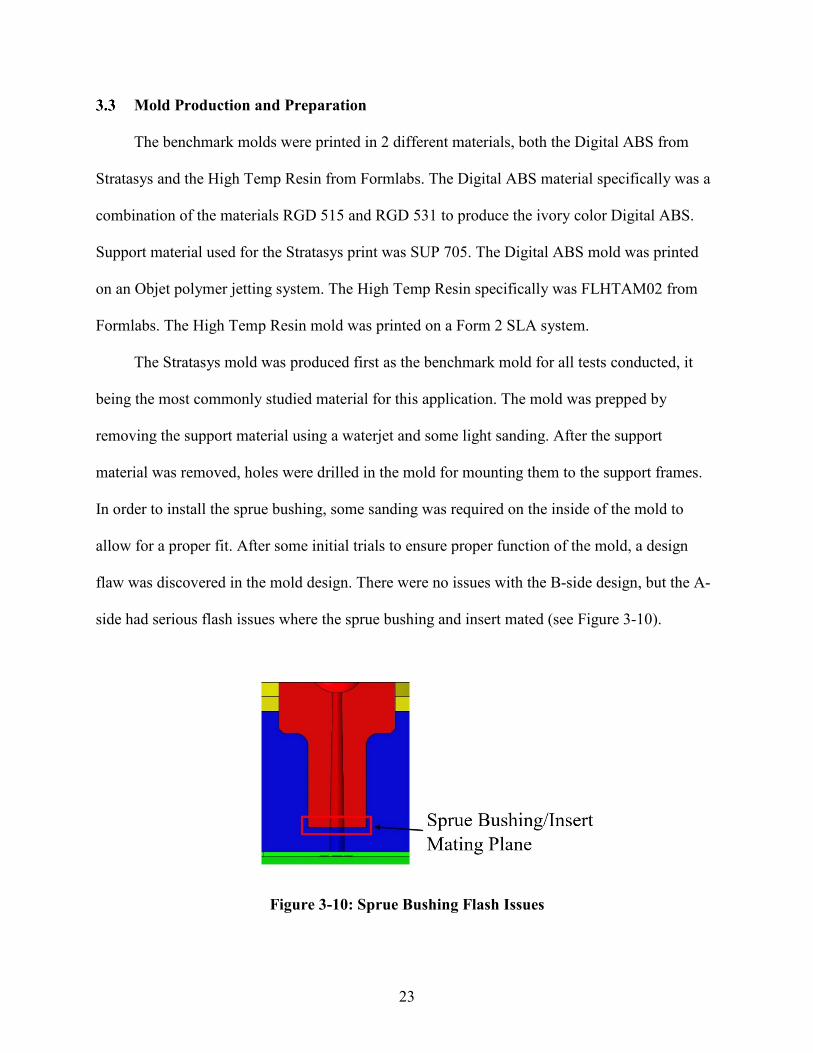
flaw was discovered in the mold design. There were no issues with the B-side design, but the A-
side had serious flash issues where the sprue bushing and insert mated (see Figure 3-10).
Figure 3-10: Sprue Bushing Flash Issues
24
This issue made it impossible for parts to be removed unless the A-side assembly was
disassembled, and the flash removed and then reassembled. This was not an acceptable process,
so a solution was needed. Different methods were tried out but the method that worked best was
applying a layer of high temp flash tape to the end of the sprue bushing, and then applying high
temp epoxy to the taped end of the sprue bushing and to the inside of the mold. Then more epoxy
was applied to the inside of the sprue, where the parts interfaced. After the epoxy cured, the
sprue was then reamed out with a taper ream to remove the excess epoxy and create a smooth
seamless transition from the sprue bushing to the insert. This method worked quite well and
allowed testing to continue. Also, during initial trials during preparation, the base of the insert
was fractured while trying to disassemble the molds to remove the sprue bushing flash. This was
repaired and did not affect the testing as it was the base of the insert and did not affect the core of
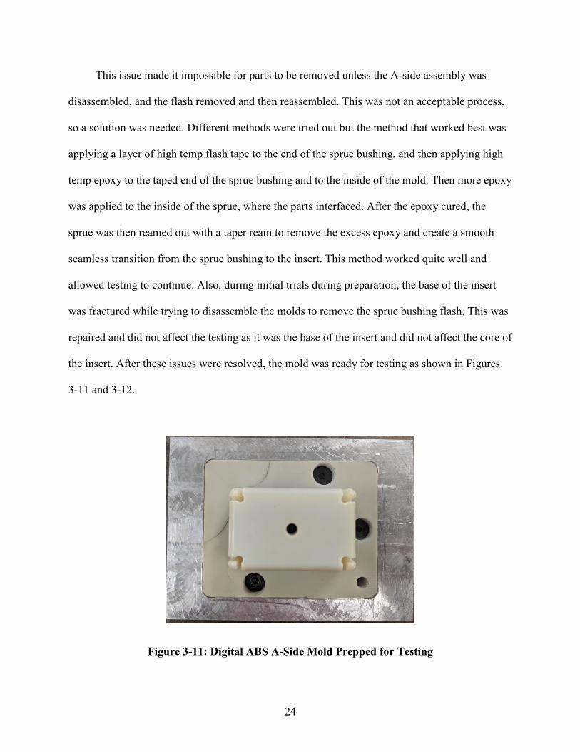
the insert. After these issues were resolved, the mold was ready for testing as shown in Figures
3-11 and 3-12.
Figure 3-11: Digital ABS A-Side Mold Prepped for Testing
25
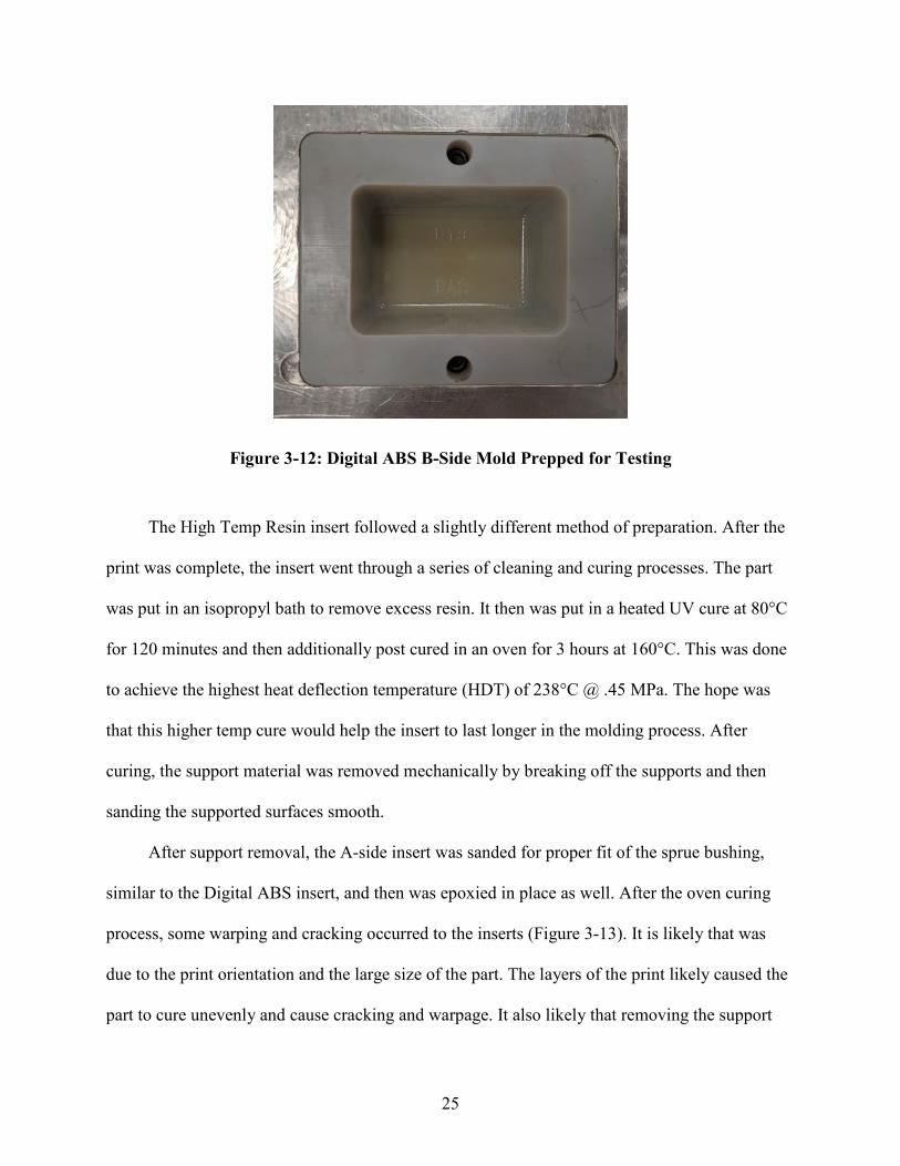
Figure 3-12: Digital ABS B-Side Mold Prepped for Testing
The High Temp Resin insert followed a slightly different method of preparation. After the
print was complete, the insert went through a series of cleaning and curing processes. The part
was put in an isopropyl bath to remove excess resin. It then was put in a heated UV cure at 80°C
for 120 minutes and then additionally post cured in an oven for 3 hours at 160°C. This was done
to achieve the highest heat deflection temperature (HDT) of 238°C @ .45 MPa. The hope was
that this higher temp cure would help the insert to last longer in the molding process. After
curing, the support material was removed mechanically by breaking off the supports and then
sanding the supported surfaces smooth.
After support removal, the A-side insert was sanded for proper fit of the sprue bushing,
similar to the Digital ABS insert, and then was epoxied in place as well. After the oven curing
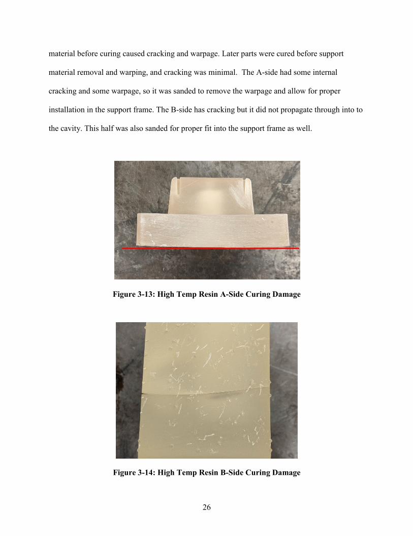
process, some warping and cracking occurred to the inserts (Figure 3-13). It is likely that was
due to the print orientation and the large size of the part. The layers of the print likely caused the
part to cure unevenly and cause cracking and warpage. It also likely that removing the support
26
material before curing caused cracking and warpage. Later parts were cured before support
material removal and warping, and cracking was minimal. The A-side had some internal
cracking and some warpage, so it was sanded to remove the warpage and allow for proper
installation in the support frame. The B-side has cracking but it did not propagate through into to
the cavity. This half was also sanded for proper fit into the support frame as well.
Figure 3-13: High Temp Resin A-Side Curing Damage
Figure 3-14: High Temp Resin B-Side Curing Damage
27
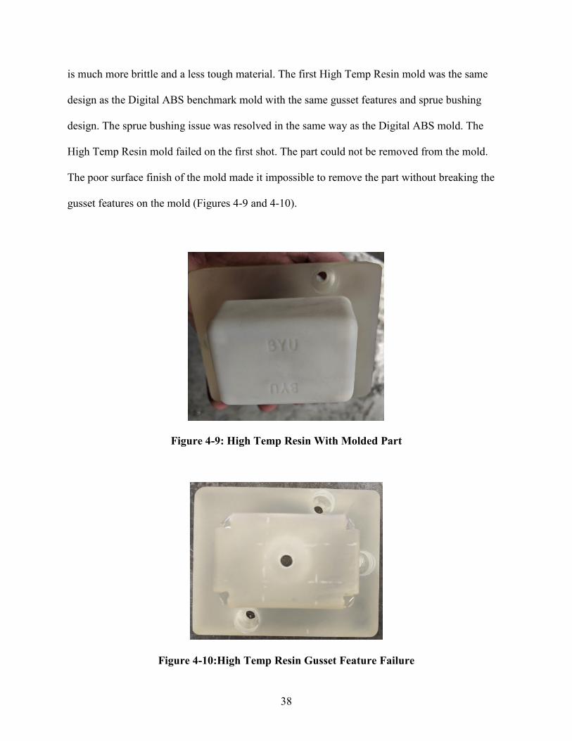
After initial testing to ensure proper function of the High Temp Resin inserts, the part
very quickly failed. The results of the test will be discussed in more detail later but, in brief, the
surface finish of the High Temp Resin was very poor in comparison to the Digital ABS insert
which made the molded part removal very difficult. While attempting to remove the part, the
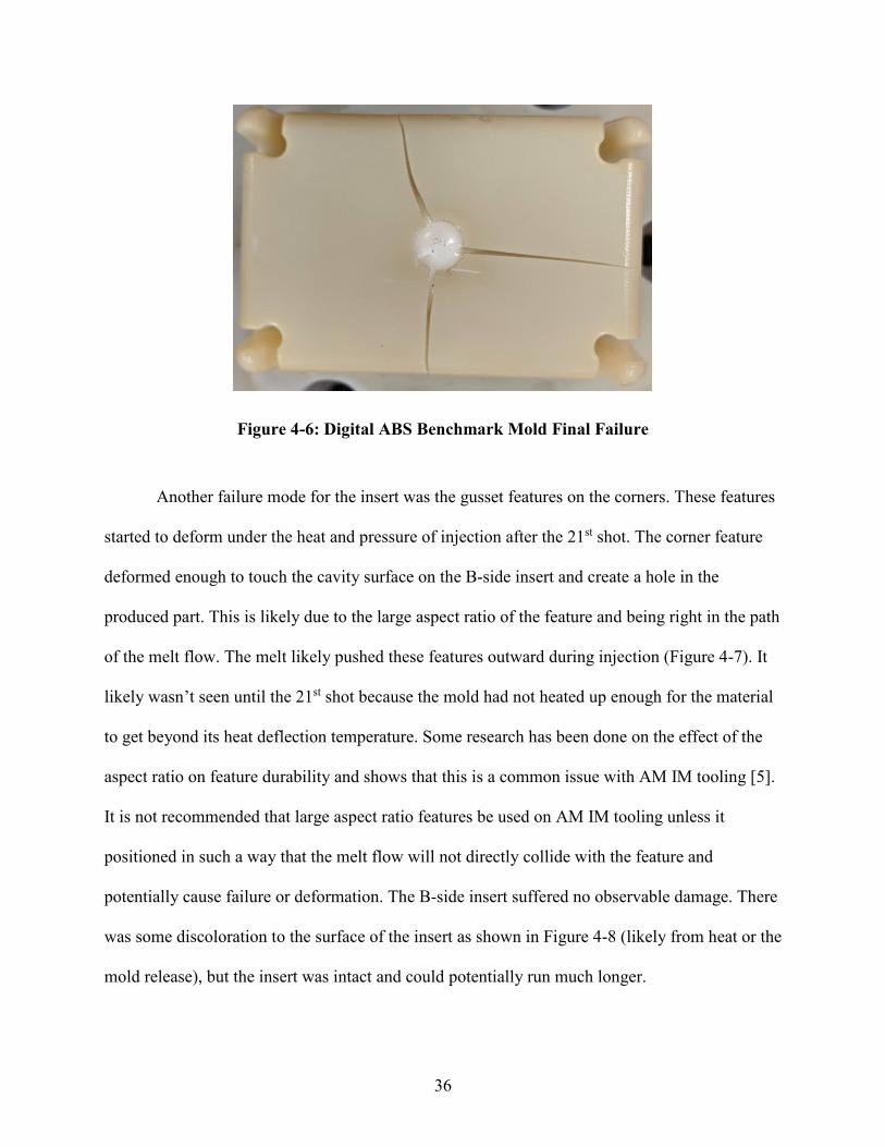
gusset features broke off and rendered the A-side insert unusable. This same gusset feature on
the Digital ABS mold also proved to be a failure mode. Although the Digital ABS mold features
did not break. They would bend outward due to the heat and pressure of injection. Because this
was a common failure mode, it was decided that this feature would be removed for future inserts
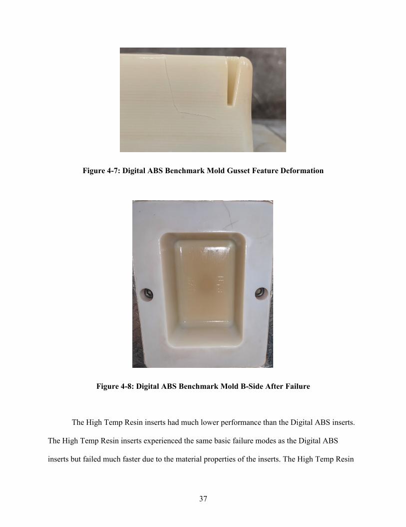
as it was not the focus of the study and could potentially cause premature failure of the insert.
Despite it being removed for future testing, it is worth noting the capabilities of the Digital ABS
material for being able to mold so many parts with this feature still present. After this initial part
failure, the A-side insert was re-printed without the gusset features and then prepared for test in
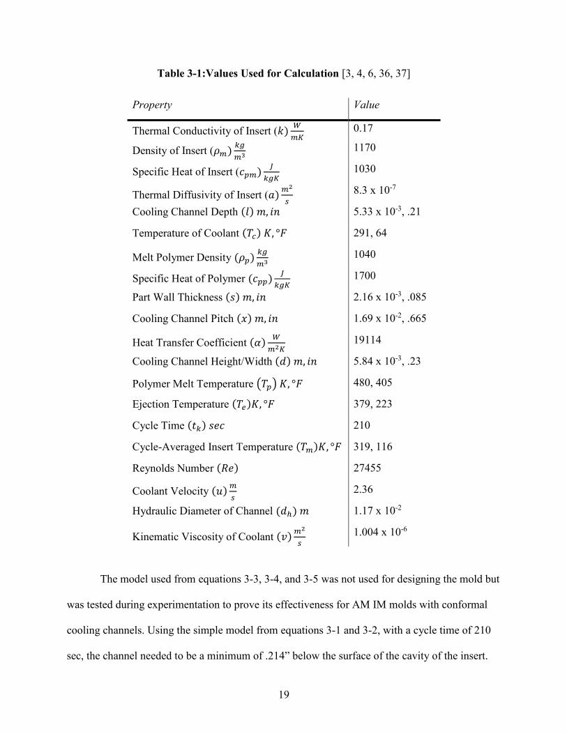
the same manner as described above but this time, the surface of the A-side core insert was
sanded to a smooth finish for easier part removal.
The Digital ABS inserts with conformal cooling channels were then printed. They were
printed with the same Digital ABS materials as mentioned above. The Rev 1 inserts were printed
first. The support material on the exterior of the inserts were removed first and then the internal
support material that created the cooling channels was then attempted to be removed. What could
be removed with a water jet, was easily removed but deep inside the channels, the water jet was
not strong enough to remove the material. The main issue with this was that when the parts were
requested to be printed, the assumption was that the soluble support material, SUP 706 was
going to be used for the print and that the support material removal would be a simple process. It
was, however, printed with SUP 705 which only slightly softens when soaked in a sodium
28
hydroxide solution unlike SUP 706 which is much easier to remove after being soaked in a
similar solution. Because of the design of the channels, there was no way that the support
material could be removed without damaging the mold. The manifold type design made it
extremely difficult.
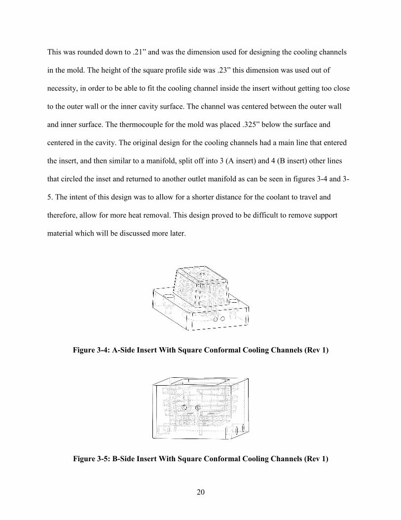
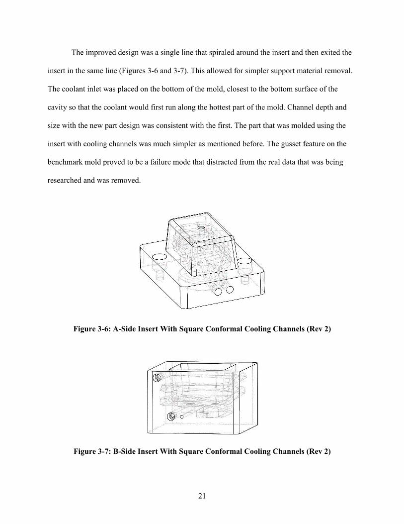
After it was determined that the support material could not be removed, the Rev 2 mold
was designed and then printed. The printing supplier did not have SUP 706 so the hope was that
with the single channel printed with the same SUP 705 that the material could be removed with a
long wire or cable by pushing it through the channel. The Rev 2 mold was then printed, and the
support material was attempted to be removed. Because the channel was a single channel and
much longer than the Rev 1 mold, a wire could not be pushed all the way through the channel to
remove the support material. Other attempts at soaking the part in a heated sodium hydroxide
bath for extended periods of time with good circulation helped to soften the support material but
the material was still not able to be removed.
With limited resources, it was resolved that getting at least the B-side of the mold to have
channels would be sufficient to get data for testing. The B-side insert had an exterior wall that
could be drilled into and allow for easier access to the channel so that the support material could
be removed. A series of holes were drilled on the outside of the B-side insert, the support
material was removed, and then the holes were blocked up with set screws and RTV silicone.
Although this was not the ideal setup for the tests to be conducted, it would still allow for data to
be collected on the effectiveness of the channels at controlling the temperature of the insert and
could give a good indication at how it could potentially improve the life of the tool. It can be said
with a high degree of confidence that the support material could be removed with much more
ease if it were originally printed with SUP 706.
29
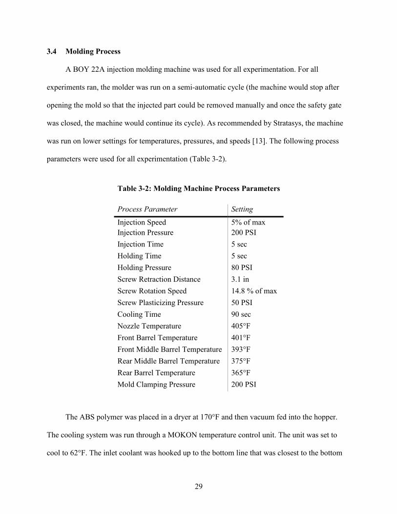
Molding Process
A BOY 22A injection molding machine was used for all experimentation. For all
experiments ran, the molder was run on a semi-automatic cycle (the machine would stop after
opening the mold so that the injected part could be removed manually and once the safety gate
was closed, the machine would continue its cycle). As recommended by Stratasys, the machine
was run on lower settings for temperatures, pressures, and speeds [13]. The following process
parameters were used for all experimentation (Table 3-2).
Table 3-2: Molding Machine Process Parameters
Process Parameter Setting
Injection Speed 5% of max Injection Pressure 200 PSI Injection Time 5 sec Holding Time 5 sec Holding Pressure 80 PSI Screw Retraction Distance 3.1 in Screw Rotation Speed 14.8 % of max Screw Plasticizing Pressure 50 PSI Cooling Time 90 sec Nozzle Temperature 405°F Front Barrel Temperature 401°F Front Middle Barrel Temperature 393°F Rear Middle Barrel Temperature 375°F Rear Barrel Temperature 365°F Mold Clamping Pressure 200 PSI
The ABS polymer was placed in a dryer at 170°F and then vacuum fed into the hopper.
The cooling system was run through a MOKON temperature control unit. The unit was set to
cool to 62°F. The inlet coolant was hooked up to the bottom line that was closest to the bottom
30
of the cavity so that the coolest water would contact the hottest part of the mold. The basic steps
that were followed while running the molding machine was as follows: spray the mold surface
with mold release, close the safety gate, press start, mold closes, screw advances and injects the
polymer melt, the screw rotates and retracts, the part cools, the mold opens, the safety gate is
opened, and the part is removed. This process was followed for all tests. At times, there was
some difficulties with the molds and there were occasional pauses between cycles to address
issues and therefore, the average cycle time was 210 seconds.
Insert Test Method and Analysis Method
The method used to test the inserts was simple and straight forward. The first benchmark
Digital ABS mold was run until failure while collecting temperature data from the insert. Due to
time constraints, this first test was done in 3 separate runs. The purpose of this test was to set a
baseline from which all other tests could be compared. The High Temp Resin inserts were run
until failure as well. The final tests that were run were also until failure, but the number of shots
run on the insert was not a metric for performance of the insert. This was not a metric for
performance since only one half of the mold was being tested. The A-side insert was not cooled
and therefore failed faster than if it had been cooled. The intent of the final cooling tests was to
collect data on how the conformal cooling channels performed and to determine the actual cycle-
averaged mold temperature of the insert being tested [30, 31, 32].
The definition of insert failure was the point at which no more parts could be made with
the insert. This was quite obvious in all cases and was not difficult to determine. The number of
shots that any insert could produce was not a metric that determined success or failure of the
insert but provided a quick and simple way to compare between materials. It was not used as a
metric to determine the results of this study.
31
The method used for testing the inserts was modeled after work done by Natti [32], Sachs
[12], and Davoudinejad [6]. The models that were used to design the cooling channels were the
key metric of performance of the inserts and the main insight into how well the conformal
cooling channels improved the life of the insert. The intent was to create a design based off of a
model and then to test the model and determine how well the model can inform the design
process. The hope was that the model would give a close representation of how the insert would
actually perform.
Another key metric was the cycle-averaged temperature of the mold. As stated previously
in this paper, a key metric to measure cooling channel performance is how well the insert can
stay at or below 120°F, which has been shown to significantly improve the life of an AM IM tool
[5, 6, 13]. When the mold stays at a cooler temperature, there is less risk of the mold being
damaged and less risk of a flexural failure [5].
32
4 RESULTS AND DISCUSSION
Insert Failure
As mentioned earlier, insert failure is a common metric used for the performance of an AM
IM tooling. This method will be used for demonstrating the performance of the benchmark
Digital ABS mold and the High Temp Resin molds. The number of shots that the insert was able
to successfully receive before catastrophic failure was the metric used to compare the initial
molds. The first mold, made from Digital ABS, performed well and was able to produce 66 shots
before catastrophic failure. The High Temp Resin mold was able to produce 3 shots before
catastrophic failure.
The mold ran at an average temperature of 138°F with a peak temperature of 185°F. The
mold took approximately 30 minutes to heat up to a more stable temperature. Once heated up,
the mold had an average temperature of about 155°F. Because of design flaws with the sprue
bushing, there were interruptions in the molding process and the recorded data was somewhat
lacking. Much more consistent and accurate data could potentially be recorded with a different
sprue/runner/gate design as it would allow for more consistent molding and the part would be
much easier to remove. There are breaks in the cycles because issues had to be addressed while
operating (mostly issues with the sprue bushing) which caused long cycle times and allowed the
mold to cool more than desired. Below is the data from the 3 runs of the temperature of the insert
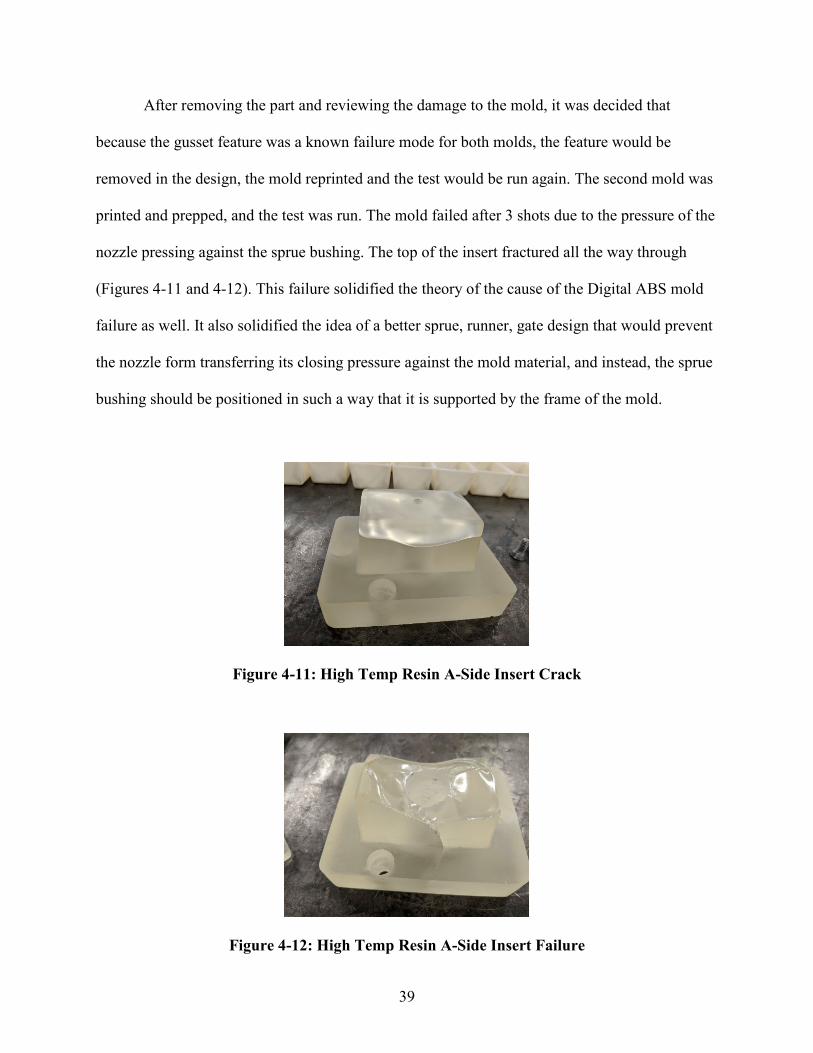
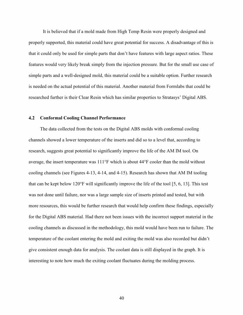
After removing the part and reviewing the damage to the mold, it was decided that
because the gusset feature was a known failure mode for both molds, the feature would be
removed in the design, the mold reprinted and the test would be run again. The second mold was
printed and prepped, and the test was run. The mold failed after 3 shots due to the pressure of the
nozzle pressing against the sprue bushing. The top of the insert fractured all the way through
(Figures 4-11 and 4-12). This failure solidified the theory of the cause of the Digital ABS mold
failure as well. It also solidified the idea of a better sprue, runner, gate design that would prevent
the nozzle form transferring its closing pressure against the mold material, and instead, the sprue
bushing should be positioned in such a way that it is supported by the frame of the mold.
Figure 4-11: High Temp Resin A-Side Insert Crack
Figure 4-12: High Temp Resin A-Side Insert Failure
40
It is believed that if a mold made from High Temp Resin were properly designed and
properly supported, this material could have great potential for success. A disadvantage of this is
that it could only be used for simple parts that don’t have features with large aspect ratios. These
features would very likely break simply from the injection pressure. But for the small use case of
simple parts and a well-designed mold, this material could be a suitable option. Further research
is needed on the actual potential of this material. Another material from Formlabs that could be
researched further is their Clear Resin which has similar properties to Stratasys’ Digital ABS.
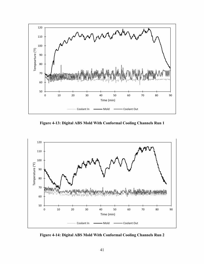
Conformal Cooling Channel Performance
The data collected from the tests on the Digital ABS molds with conformal cooling
channels showed a lower temperature of the inserts and did so to a level that, according to
research, suggests great potential to significantly improve the life of the AM IM tool. On
average, the insert temperature was 111°F which is about 44°F cooler than the mold without
cooling channels (see Figures 4-13, 4-14, and 4-15). Research has shown that AM IM tooling
that can be kept below 120°F will significantly improve the life of the tool [5, 6, 13]. This test
was not done until failure, nor was a large sample size of inserts printed and tested, but with
more resources, this would be further research that would help confirm these findings, especially
for the Digital ABS material. Had there not been issues with the incorrect support material in the
cooling channels as discussed in the methodology, this mold would have been run to failure. The
temperature of the coolant entering the mold and exiting the mold was also recorded but didn’t
give consistent enough data for analysis. The coolant data is still displayed in the graph. It is
interesting to note how much the exiting coolant fluctuates during the molding process.
41
Figure 4-13: Digital ABS Mold With Conformal Cooling Channels Run 1
Figure 4-14: Digital ABS Mold With Conformal Cooling Channels Run 2
50
60
70
80
90
100
110
120
0 10 20 30 40 50 60 70 80 90
Tem
pear
ture
(°F)
Time (min)
Coolant In Mold Coolant Out
50
60
70
80
90
100
110
120
0 10 20 30 40 50 60 70 80 90
Tem
pera
ture
(°F)
Time (min)
Coolant In Mold Coolant Out
42
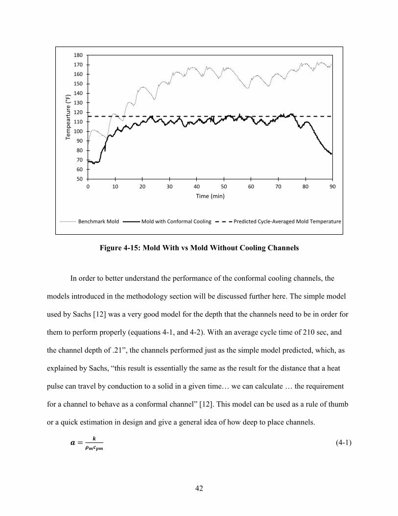
Figure 4-15: Mold With vs Mold Without Cooling Channels
In order to better understand the performance of the conformal cooling channels, the
models introduced in the methodology section will be discussed further here. The simple model
used by Sachs [12] was a very good model for the depth that the channels need to be in order for
them to perform properly (equations 4-1, and 4-2). With an average cycle time of 210 sec, and
the channel depth of .21”, the channels performed just as the simple model predicted, which, as
explained by Sachs, “this result is essentially the same as the result for the distance that a heat
pulse can travel by conduction to a solid in a given time… we can calculate … the requirement
for a channel to behave as a conformal channel” [12]. This model can be used as a rule of thumb
or a quick estimation in design and give a general idea of how deep to place channels.
𝒂𝒂 = 𝒌𝒌𝝆𝝆𝒎𝒎𝒄𝒄𝒑𝒑𝒎𝒎
(4-1)
50
60
70
80
90
100
110
120
130
140
150
160
170
180
0 10 20 30 40 50 60 70 80 90
Tem
pear
ture
(°F)
Time (min)
Benchmark Mold Mold with Conformal Cooling Predicted Cycle-Averaged Mold Temperature
43
𝒍𝒍 < �𝒂𝒂𝒕𝒕𝒌𝒌 (4-2)
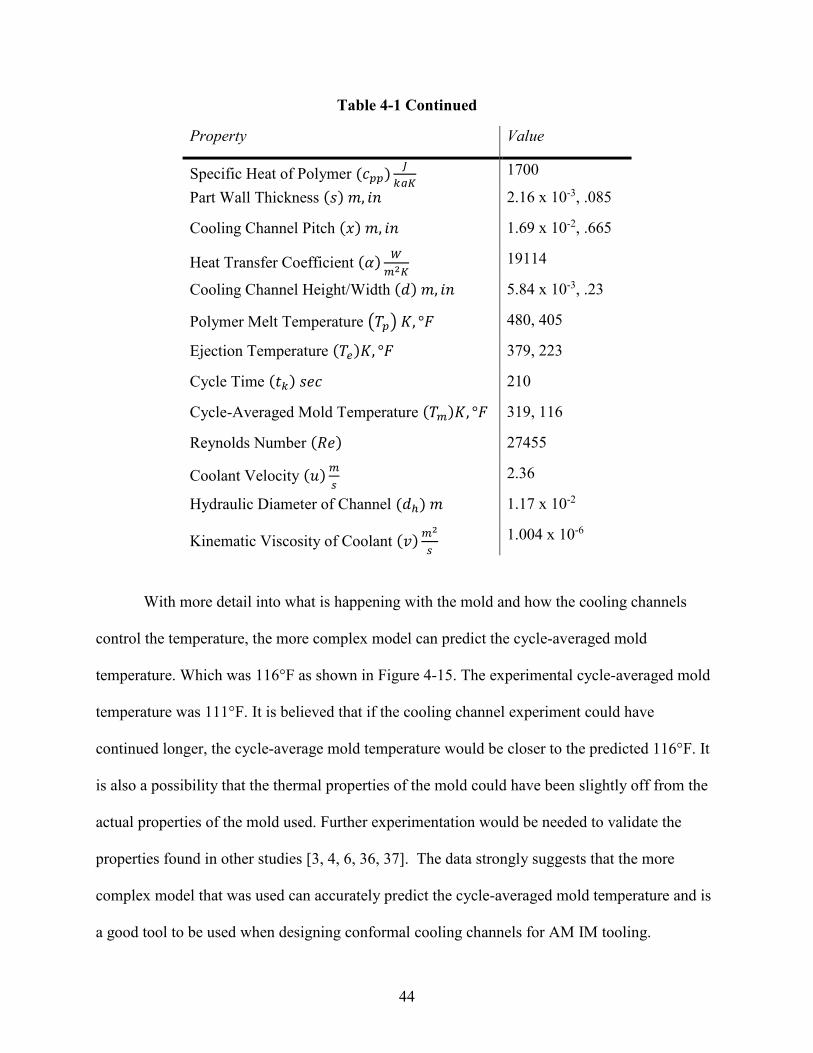
In this study, the complex model (equations 4-3, 4-4, and 4-5) was used after
experimentation with the intent to validate the model so that it can be used in future studies or in
industry applications. When the model is used with more unknown data, some more work is
required to find unknown values, such as cycle time. Kanbur and Rao go into great detail on how
this model can be iterated to find the optimal value for any unknown variable [30, 32]. These
values were found experimentally in this study. The values that were discovered experimentally
that were used in this model were the ejection temperature and the cycle time. Below are the
same equations and values used as shown in the methodology section but are presented again
here for quicker reference.
𝑻𝑻𝒎𝒎 = 𝑻𝑻𝒄𝒄 +𝝆𝝆𝒑𝒑∙𝒄𝒄𝒑𝒑𝒑𝒑∙
𝒔𝒔𝟐𝟐∙(𝟐𝟐∙𝒌𝒌∙𝒙𝒙+𝜶𝜶∙𝟒𝟒∙𝒅𝒅∙𝒍𝒍)∙�𝑻𝑻𝒑𝒑−𝑻𝑻𝑹𝑹�
𝜶𝜶∙𝟒𝟒∙𝒅𝒅∙𝒌𝒌∙𝒕𝒕𝒌𝒌 (4-3)
𝜶𝜶 = .𝟎𝟎𝟎𝟎𝟎𝟎𝟎𝟎𝟎𝟎𝟎𝟎𝒅𝒅
∙ 𝑹𝑹𝑹𝑹𝟎𝟎.𝟖𝟖 (4-4)
𝑹𝑹𝑹𝑹 = 𝒖𝒖 ∙ 𝒅𝒅𝒉𝒉𝒗𝒗
(4-5)
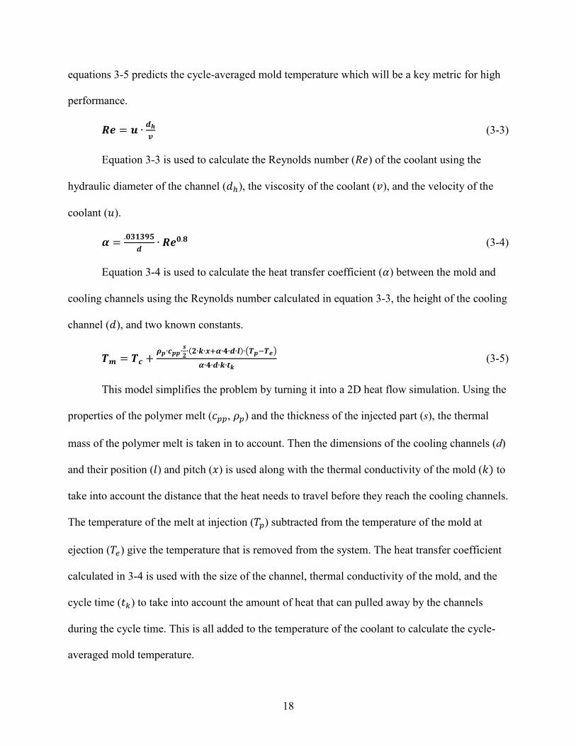
Table 4-1:Values Used for Calculation [3, 4, 6, 36, 37]
Property Value
Thermal Conductivity of Insert (𝑘𝑘) 𝑊𝑊𝑚𝑚𝑚𝑚
0.17
Density of Insert (𝜌𝜌𝑚𝑚) 𝑘𝑘𝑘𝑘𝑚𝑚3 1170
Specific Heat of Insert (𝑐𝑐𝑝𝑝𝑚𝑚) 𝐽𝐽𝑘𝑘𝑘𝑘𝑚𝑚
1030
Thermal Diffusivity of Insert (𝑎𝑎)𝑚𝑚2
𝑠𝑠 8.3 x 10⁻⁷
Cooling Channel Depth (𝑙𝑙) 𝑚𝑚, 𝑖𝑖𝑖𝑖 5.33 x 10⁻³, .21
Temperature of Coolant (𝑇𝑇𝑐𝑐) 𝐾𝐾, °𝐹𝐹 291, 64
Melt Polymer Density (𝜌𝜌𝑝𝑝) 𝑘𝑘𝑘𝑘𝑚𝑚3 1040
44
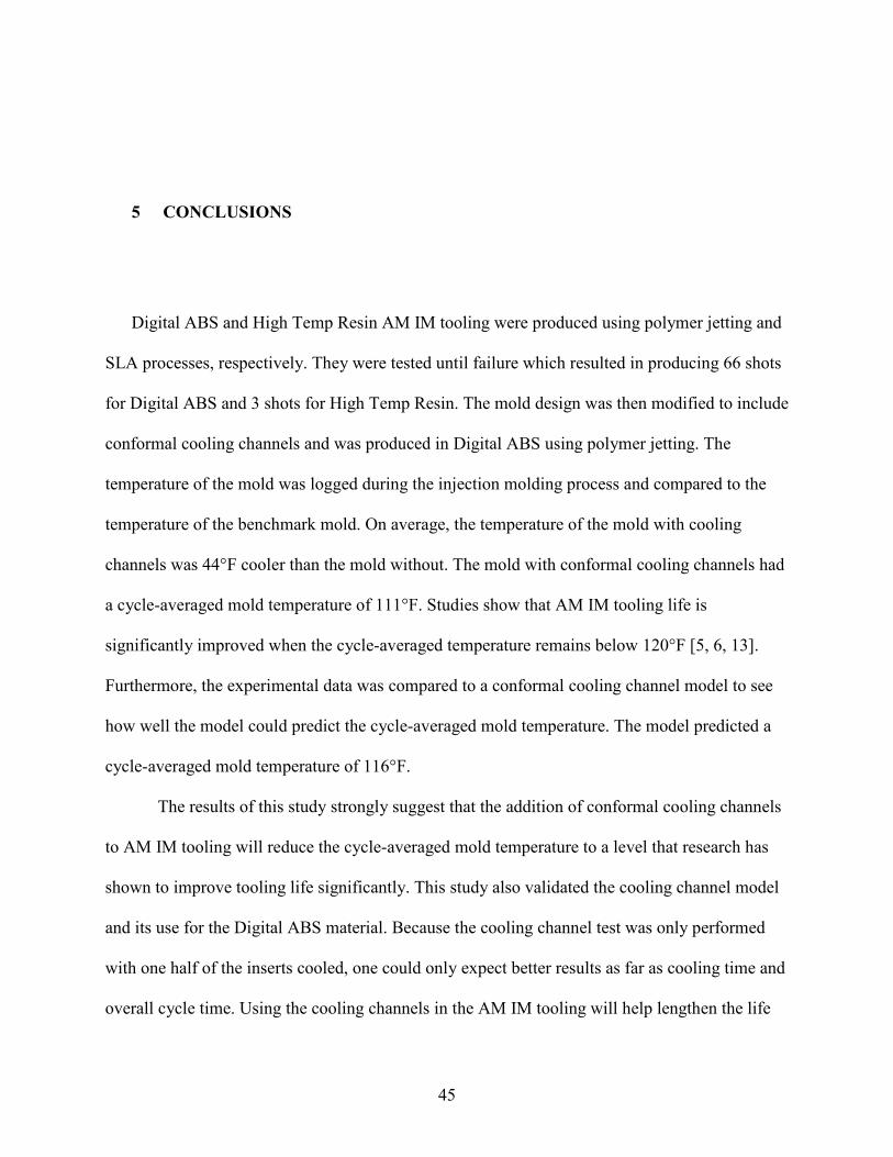
Table 4-1 Continued
Property
Value
Specific Heat of Polymer (𝑐𝑐𝑝𝑝𝑝𝑝) 𝐽𝐽𝑘𝑘𝑘𝑘𝑚𝑚
1700
Part Wall Thickness (𝑠𝑠) 𝑚𝑚, 𝑖𝑖𝑖𝑖 2.16 x 10⁻³, .085
Cooling Channel Pitch (𝑥𝑥) 𝑚𝑚, 𝑖𝑖𝑖𝑖 1.69 x 10⁻², .665
Heat Transfer Coefficient (𝛼𝛼) 𝑊𝑊𝑚𝑚2𝑚𝑚
19114
Cooling Channel Height/Width (𝑑𝑑) 𝑚𝑚, 𝑖𝑖𝑖𝑖 5.84 x 10⁻³, .23
Polymer Melt Temperature �𝑇𝑇𝑝𝑝� 𝐾𝐾, °𝐹𝐹 480, 405
Ejection Temperature (𝑇𝑇𝑒𝑒)𝐾𝐾, °𝐹𝐹 379, 223
Cycle Time (𝑡𝑡𝑘𝑘) 𝑠𝑠𝑅𝑅𝑐𝑐 210
Cycle-Averaged Mold Temperature (𝑇𝑇𝑚𝑚)𝐾𝐾, °𝐹𝐹 319, 116
Reynolds Number (𝑅𝑅𝑅𝑅) 27455
Coolant Velocity (𝑢𝑢)𝑚𝑚𝑠𝑠
2.36
Hydraulic Diameter of Channel (𝑑𝑑ℎ) 𝑚𝑚 1.17 x 10⁻²
Kinematic Viscosity of Coolant (𝑣𝑣)𝑚𝑚2
𝑠𝑠 1.004 x 10⁻⁶
With more detail into what is happening with the mold and how the cooling channels
control the temperature, the more complex model can predict the cycle-averaged mold
temperature. Which was 116°F as shown in Figure 4-15. The experimental cycle-averaged mold
temperature was 111°F. It is believed that if the cooling channel experiment could have
continued longer, the cycle-average mold temperature would be closer to the predicted 116°F. It
is also a possibility that the thermal properties of the mold could have been slightly off from the
actual properties of the mold used. Further experimentation would be needed to validate the
properties found in other studies [3, 4, 6, 36, 37]. The data strongly suggests that the more
complex model that was used can accurately predict the cycle-averaged mold temperature and is
a good tool to be used when designing conformal cooling channels for AM IM tooling.
45
5 CONCLUSIONS
Digital ABS and High Temp Resin AM IM tooling were produced using polymer jetting and
SLA processes, respectively. They were tested until failure which resulted in producing 66 shots
for Digital ABS and 3 shots for High Temp Resin. The mold design was then modified to include
conformal cooling channels and was produced in Digital ABS using polymer jetting. The
temperature of the mold was logged during the injection molding process and compared to the
temperature of the benchmark mold. On average, the temperature of the mold with cooling
channels was 44°F cooler than the mold without. The mold with conformal cooling channels had
a cycle-averaged mold temperature of 111°F. Studies show that AM IM tooling life is
significantly improved when the cycle-averaged temperature remains below 120°F [5, 6, 13].
Furthermore, the experimental data was compared to a conformal cooling channel model to see
how well the model could predict the cycle-averaged mold temperature. The model predicted a
cycle-averaged mold temperature of 116°F.
The results of this study strongly suggest that the addition of conformal cooling channels
to AM IM tooling will reduce the cycle-averaged mold temperature to a level that research has
shown to improve tooling life significantly. This study also validated the cooling channel model
and its use for the Digital ABS material. Because the cooling channel test was only performed
with one half of the inserts cooled, one could only expect better results as far as cooling time and
overall cycle time. Using the cooling channels in the AM IM tooling will help lengthen the life
46
of the tool and help reduce the cycle time of part production. This solution has the potential to
expand the use case for AM IM tooling by allowing for a higher volume of parts produced
whether it be for production parts, for prototyping and testing, or for mold design validation.
The major focus of this study was the effect that the conformal cooling channels had on
the cycle-averaged mold temperature. More research could be done with conformal cooling
channels to see how it effects the life of the tooling over a complete tool life cycle. Other, more
cost effective, materials should be studied as well, and the addition of conformal cooling
channels may expand the number of materials able to be used for IM tooling.
47
REFERENCES
[1] Salonitis, K. "Stereolithography.” Comprehensive Materials Processing 10 (2014): 19-67. [2] Stampfl, J., S. Baudis, C. Heller, R. Liska, A. Neumeister, R. Kling, A. Ostendorf, and M. Spitzbart. "Photopolymers with tunable mechanical properties processed by laser-based high-resolution stereolithography." Journal of Micromechanics and Microengineering 18, no. 12 (2008): 125014. [3] Mendible, G. A., J. A. Rulander, and S. P. Johnston. "Comparative study of rapid and conventional tooling for plastics injection molding." Rapid Prototyping Journal (2017). [4] Volpato, N., D. M. Solis, and C. A. Costa. "An analysis of Digital ABS as a rapid tooling material for polymer injection moulding." International Journal of Materials and Product Technology 52, no. 1-2 (2016): 3-16. [5] Rahmati, S., and P. Dickens. "Rapid tooling analysis of Stereolithography injection mould tooling." International Journal of Machine Tools and Manufacture 47, no. 5 (2007): 740-747. [6] Davoudinejad, A., M. Bayat, D. B. Pedersen, Y. Zhang, J. H. Hattel, and G. Tosello. "Experimental investigation and thermo-mechanical modelling for tool life evaluation of photopolymer additively manufactured mould inserts in different injection moulding conditions." The International Journal of Advanced Manufacturing Technology 102, no. 1-4 (2019): 403-420. [7] Schuh, G., G. Bergweiler, G. Lukas, and M. Oly. "Towards Temperature Control Measures for Polymer Additive Injection Molds." Procedia CIRP 93 (2020): 90-95. [8] Diegel, O. "Additive Manufacturing: An Overview." Comprehensive Materials Processing 10 (2014): 3-18. [9] Chua, C. K, K. F. Leong, and Z. H. Liu. "Rapid tooling in manufacturing." Handbook of Manufacturing Engineering and Technology (2013): 1-22. [10] Ong, H. S., C. K. Chua, and C. M. Cheah. "Rapid moulding using epoxy tooling resin." The International Journal of Advanced Manufacturing Technology 20, no. 5 (2002): 368-374. [11] Tosello, G., A. Charalambis, L. Kerbache, M. Mischkot, D. B. Pedersen, M. Calaon, and H. N. Hansen. "Value chain and production cost optimization by integrating additive manufacturing
48
in injection molding process chain." The International Journal of Advanced Manufacturing Technology 100, no. 1-4 (2019): 783-795. [12] Sachs, E., E. Wylonis, S. Allen, M. Cima, and H. Guo. "Production of injection molding tooling with conformal cooling channels using the three dimensional printing process." Polymer Engineering & Science 40, no. 5 (2000): 1232-1247. [13] “PolyJet for Injection Molding Technical Application Guide.” Stratasys. Accessed September 26, 2020. https://www.stratasys.com/resources/search/resource-guides/polyjet-injection-molding. [14] “Injection Molding from 3D Printed Molds: A Study of Low-Volume Production of Small Plastic Parts.” Formlabs, June 2020. https://3d.formlabs.com/injection-molding/. [15] “Standard Materials for High-Resolution Rapid Prototyping.” n.d. Accessed October 8, 2020. https://formlabs-media.formlabs.com/datasheets/Clear_Resin_Technical.pdf. [16] “High Temp High Temp Resin for Heat Resistance.” 2016. https://formlabs-media.formlabs.com/datasheets/High_Temp_Technical.pdf. [17] “Digital ABS Plus: A Heat Resistant 3D Printing Material.” n.d. Stratasys. Accessed October 8, 2020. https://www.stratasys.com/materials/search/digital-abs-plus. [18] Nelson, J. W., J. J. LaValle, B. D. Kautzman, J. K. Dworshak, E. M. Johnson, and C. A. Ulven. "Injection Molding with an Additive Manufacturing Tool: Study shows that 3D printed tools can create parts comparable to those made with P20 tools, at a much lower cost and lead time." Plastics Engineering 73, no. 7 (2017): 60-66. [19] Storsanden, A. L., M. Våle, and R. M. C. Ratnayake. "Use of additive manufacturing for polymer tooling: Case study from reaction injection molding." In 2017 IEEE International Conference on Industrial Engineering and Engineering Management (IEEM), (2017): 1607-1610. [20] Mischkot, M., A. Davoudinejad, A. Charalambis, T. Hofstätter, G. Tosello, D. B. Pedersen, and H. Nørgaard. "Dimensional accuracy of Acrylonitrile Butadiene Styrene injection molded parts produced in a pilot production with an additively manufactured insert." In 33rd Conference of the Polymer Processing Society, at Cancun, Mexico. 2017. [21] Zhang, Y., D. B. Pedersen, A. S. Gøtje, M. Mischkot, and G. Tosello. "A Soft Tooling process chain employing Additive Manufacturing for injection molding of a 3D component with micro pillars." Journal of Manufacturing Processes 27 (2017): 138-144. [22] Simpson, P., A. D. Zakula, J. Nelson, J. K. Dworshak, E. M. Johnson, and C. A. Ulven. "Injection molding with an additive manufactured tool." Polymer Engineering & Science 59, no. 9 (2019): 1911-1918.
[23] Etesami, F., C. Mullens, R. Sahli, and T. Webb. "Improving the Performance of 3D Printed Molds for Plastic Injection Molding." Proceedings of 34th International Conference on Computers and Their Applications, vol 58 (2019): 438-443. [24] Ferreira, J. C., and A. Mateus. "Studies of rapid soft tooling with conformal cooling channels for plastic injection moulding." Journal of Materials Processing Technology 142, no. 2 (2003): 508-516. [25] Shinde, M. S., and K. M. Ashtankar. "Additive manufacturing–assisted conformal cooling channels in mold manufacturing processes." Advances in Mechanical Engineering 9, no. 5 (2017): 1687814017699764. [26] Tang, Y., Z. Gao, and Y. F. Zhao. "Design of conformal porous structures for the cooling system of an injection mold fabricated by Additive Manufacturing Process." Journal of Mechanical Design 141, no. 10 (2019). [27] Au, K. M., and K. M. Yu. "A scaffolding architecture for conformal cooling design in rapid plastic injection moulding." The International Journal of Advanced Manufacturing Technology 34, no. 5-6 (2007): 496-515. [28] Janczyk, M., R. McLaughlin, and P. McCarthy. "Rapid stereolithography tooling for injection molding: the effect of cooling channel geometry." Journal of Injection Molding Technology (USA) 1, no. 1 (1997): 72-78. [29] Wylonis, E. M. "Production of injection molding tooling with conformal cooling channels using the three dimensional printing process." PhD diss., Massachusetts Institute of Technology, 1995. [30] Kanbur, B. B., S. Suping, and F. Duan. "Design and optimization of conformal cooling channels for injection molding: a review." The International Journal of Advanced Manufacturing Technology 106, no. 7-8 (2020): 3253-3271. [31] Xu, X., E. Sachs, and S. Allen. "The design of conformal cooling channels in injection molding tooling." Polymer Engineering & Science 41, no. 7 (2001): 1265-1279. [32] Rao, N. S., G. Schumacher, N. R. Schott, and K. T. O’brien. "Optimization of Cooling Systems in Injection Molds by an Easily Applicable Analytical Model." Journal of Reinforced Plastics and Composites 21, no. 5 (2002): 451-459. [33] Strong, A. B. Plastics: Materials and Processing. Upper Saddle River, NJ: Pearson Prentice Hall, 2006. [34] Kazmer, D. Injection Mold Design Engineering. Munich, 2016. [35] Wang, Y., K. Yu, and C. C.L. Wang. "Spiral and conformal cooling in plastic injection molding." Computer-Aided Design 63 (2015): 1-11.