6
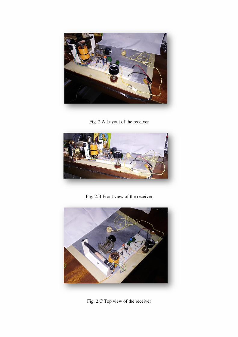
Designing Simple Low-Voltage Vacumm-Tube Regenerative Receivers Ramon Vargas Patron [email protected] [email protected] INICTEL-UNI The design and construction of RF and AF electronic circuits using vintage discrete technologies has been a very rewarding part-time entertainment for decades, and will certainly continue to be so in the future. You can find everywhere experimenters acquainted with solid-state technology replicating with great interest old technology approaches for amplifiers, oscillators and radio receivers, and even mixing them in a particular design. We are referring to the use of Galena (PbS), Pyrates (FeS), germanium and silicon diodes, vacumm tubes, germanium and silicon bipolar transistors (BJTs), junction field effect transistors (JFETs), 555 IC timers, and even logic ICs as signal amplifiers when biased for linear operation. We can find there are myriads of possible applications. This article will show how to build an AM MW BCB regenerative receiver using mixed technologies, specifically, vacumm tube, JFET and BJT. We would like a vacumm-tube RF stage followed by a JFET buffer stage and a BJT pre-amplifier, just for headphone listening. The direct approach for a regenerative receiver design employing vacumm-tube technology usually starts with a review of the technical specifications of the devices selected, the required power supply, parts and components. Amplifying tubes have generally been designed to work with more than 40Volts DC on plate (anode), imposing a threat on unaware folks. Portable electronic equipment made use of “B” batteries for the plate voltages. Common values for these were 45 Volts, 67.5 Volts and 90 Volts. “A” batteries were used for filament heating, being 1.5 Volts, 2 Volts and 7.5 Volts the most used types. A careful study of the plate-current vs plate-voltage characteritics (Ip vs Vp) of some amplifying tubes led curious experimenters to test the operation of these devices with low plate voltages. These tests were successful for many of those tubes designed for portable operation on batteries. The author tested a couple of these, i.e., a 1A5GT, a filament-type power-amplifier output pentode for use in low-drain battery-operated equipment (see Annex I), and a 2SH27L, a Russian universal pentode featuring also directly-heated cathode operation (Annex II). The suppressor grid of the first tube is internally tied to the filament (cathode), while the second tube has that grid wired for external connection. In this article we shall dedicate efforts towards the construction of a regen with the 1A5GT pentode. In a next article we will describe a Transitron negative-resistance type AM MW BCB receiver using a 2SH27L pentode. Let see Fig.1. It shows the schematic diagram of an experimental regen for medium wave frequencies built on a solderless breadboard using the 1A5GT. It uses a 1.5-Volt alkaline battery for filament heating and a 14-Volt DC supply for the “high tension”of amplifier stages. Regeneration is adjusted varying the screen grid bias voltage, and is quite smooth on its action. The “high tension” supply can be reduced to 12 Volts DC and still get