+ All Categories
Home > Documents > Development and Placement of a Sorbent-amended Thin Layer ... · Placement of the RCM did not cause...

Development and Placement of a Sorbent-amended Thin Layer ... · Placement of the RCM did not cause...

Date post: 15-Aug-2019
Category:
Upload: voquynh
View: 214 times
Download: 0 times
Share this document with a friend
24
1 Development and Placement of a Sorbent-amended Thin Layer Sediment Cap in the Anacostia River Kathleen M. McDonough 1 , Paul Murphy 1 , Jim Olsta 2 Yuewei Zhu 3 , Danny Reible 4 , and Gregory V. Lowry 1* 1 Department of Civil & Environmental Engineering, Carnegie Mellon University, Pittsburgh, PA 15213-3890, USA; Ph: 412-268-2948; fax: 412-268-7813; [email protected] 2 CETCO, 1500 West Shure Drive, Arlington Heights, Illinois 60004 3 Horne Engineering Services, Inc., 3130 Fairview Park Drive, Suite 400, Falls Church, VA 22042 4 Department of Civil Engineering, University of Texas-Austin, Austin, TX 78712, USA Manuscript Accepted for Publication in INTERNATIONAL JOURNAL OF SOIL AND SEDIMENT CONTAMINATION AUGUST 22, 2006 *Corresponding author
Transcript

1

Development and Placement of a Sorbent-amended Thin Layer Sediment Cap in the Anacostia River

Kathleen M. McDonough1, Paul Murphy1, Jim Olsta2 Yuewei Zhu3, Danny Reible4, and Gregory V. Lowry1*

1 Department of Civil & Environmental Engineering, Carnegie Mellon University, Pittsburgh, PA 15213-3890, USA; Ph: 412-268-2948; fax: 412-268-7813; [email protected]

2 CETCO, 1500 West Shure Drive, Arlington Heights, Illinois 60004 3 Horne Engineering Services, Inc., 3130 Fairview Park Drive, Suite 400, Falls Church, VA

22042 4 Department of Civil Engineering, University of Texas-Austin, Austin, TX 78712, USA

Manuscript Accepted for Publication in

INTERNATIONAL JOURNAL OF SOIL AND SEDIMENT CONTAMINATION

AUGUST 22, 2006

*Corresponding author

2

Development and Placement of a Sorbent-amended Thin Layer Sediment Cap in the Anacostia River

Kathleen M. McDonough1, Paul Murphy1, Jim Olsta2, Yuewei Zhu3, Danny Reible4, and Gregory V. Lowry1*

Abstract

Incorporating materials into sediment caps that can sequester contaminants will greatly improve

their ability to isolate contaminants in the underlying sediments from the rest of the aquatic

environment. For highly sorptive media a thin layer (cm) may be sufficient, but accurately

placing a thin layer (cm) of material over submerged contaminated sediment is difficult. A

reactive core mat (RCM) was designed to accurately place a 1.25 cm thick sorbent (coke) layer

in an engineered sediment cap. In April, 2004, Twelve 3.1 m x 31 m sections of RCM were

placed in the Anacostia River, Washington D.C. and overlain with a 15 cm layer of sand to

secure it and provide a habitat for benthic organisms to colonize without compromising the

integrity of the cap. Placement of the RCM did not cause significant sediment re-suspension or

impact site hydrology. The RCM is an inexpensive and effective method to accurately deliver

thin layers of difficult to place, high value, sorptive media into sediment caps. The approach can

also be used to place granular reactive media that can degrade or mineralize contaminants.

Key words: Sediment remediation; Sediment capping; In-situ sediment management;

Innovative remediation technologies; Remediation technologies

1 Department of Civil & Environmental Engineering, Carnegie Mellon University, Pittsburgh, PA 15213 2 CETCO, 1500 West Shure Drive, Arlington Heights, Illinois 60004 3 Horne Engineering Services, Inc., 3130 Fairview Park Drive, Suite 400, Falls Church, VA 22042 4 Department of Civil Engineering, University of Texas-Austin, Austin, TX 78712 * Corresponding author:[email protected]; 412-268-2948

3

Introduction

Sediments are a sink for hydrophobic organic contaminants (HOCs) such as polyaromatic

hydrocarbons (PAH) and polychlorinated biphenyls (PCB), and act as a continual source of

contamination to aquatic ecosystems. In-Situ Capping (ISC) is a potentially effective technology

to minimize the exposure of aquatic ecosystems to sediment contaminants and thus significantly

reduce the ecological risk associated with contaminated sediments. ISC introduces a layer of

clean material over contaminated sediment to stabilize, physically separate, and chemically

isolate the sediment from the rest of the aquatic system including the benthic organisms, aquatic

plants, and overflowing water. An analysis of ISC on the lower Fox River, WI, showed that as

long as cap integrity could be maintained, capping could rapidly and effectively reduce surficial

sediment concentrations and therefore reduce the risk associated with contaminated sediment

(Reible et al. 2003). Even when ISC is not the primary remedial approach, it may be useful in

reducing the long-term risk of residual contamination left after dredging.

Approximately one hundred sediment caps have been placed in varying environments (e.g.

rivers, bays, estuaries) and are predominantly thick (50-100 cm) sand caps (Palermo et al. 1998).

To date, fewer than ten “innovative” (e.g. thin layer caps or sorbent-amended caps) sediment

caps have been placed (Table 1). Regulatory and public acceptance of ISC with sand has

sometimes been difficult to obtain because contaminants are not removed or destroyed, and

because the ability of a sand cap to isolate contaminants for long periods of time depends upon

the site’s hydrogeology (e.g. groundwater seepage). Adding a sorbent layer to a sand cap will

prolong contaminant isolation by sequestering contaminants and retarding their transport from

the sediment into the bioactive benthic zone (Palermo et al. 1998, Murphy et al. 2006, Talbert et

4

al., 2001). The prolonged isolation allows time for inherently slow natural recovery processes

such as deposition of clean sediment over the sediment cap and/or biodegradation of

contaminants in the underlying sediment to take place. Amending sand caps with sorbents

(Figure 1) may therefore be a simple, practical, and cost-effective means to increase the time that

a sediment cap can isolate contaminants, and may increase public acceptance of in-situ capping

as a viable option to manage contaminated sediments in place. A demonstration of the use of

sorbents and other innovative cap materials for the enhancement of cap effectiveness is currently

underway in the Anacostia River, Washington, DC (Constants et al., 2005). Apatite was

employed to control metals release from the contaminated sediment and Aquablok® was

employed to control permeability of the surficial sediments. Coke was employed to control

organic contaminant release from the contaminated sediments, and the novel placement of that

material is the subject of this paper.

Strong sorbents such as activated carbon are attractive sequestration technologies because PCBs

and PAHs adsorb very strongly (Kleineidam et al. 2002; Jonker and Koelmans 2002), desorb

very slowly (Ghosh et al. 2001), and are less bioavailable when sorbed (Talley et al. 2002;

Mcleod, et al. 2004). Mcleod et al. (2004) reported that less than 5% of a tetrachlorobiphenyl

(PCB-52) adsorbed to activated carbon could be assimilated into clams digesting particles of

activated carbon with these PCBs adsorbed to them, compared to absorption efficiencies of 40%

to 90% for other types of sediment carbonaceous material (e.g. peat, wood, and diatoms).

Absorption efficiencies of PCB-52 from sediments range from 21% to 87% (Bott and Stanley,

2000). It has been demonstrated in the laboratory that capping sediment with a centimeter thick

layer of activated carbon or coke can effectively mitigate contaminant flux from sediment under

5

both diffusion and advection dominated conditions, and thus can physically isolate contaminants

in sediment from the bioactive region of the cap for decades to centuries (Murphy et al. 2006;

Zimmerman, et al. 2004).

Amending sediment caps with sorbents such as activated carbon or coke is currently constrained

by the lack of a method to accurately and cost-effectively deploy thin uniform layers (~cm) of

these low-density sorbents. Traditional placement methods for sand caps such as particle

broadcasting are simple and relatively inexpensive, but rely on the high density of the particles

for delivery. Low-density materials such as activated carbon or coke may not settle rapidly

enough to be placed accurately and uniformly in thin (cm) layers, especially in moving surface

waters such as rivers or estuaries. The use of silt curtains can reduce or eliminate problems

associated with moving water, but this adds to the cost of remediation. The low-density sorbent

materials are also more expensive than sand and need to be delivered in a thin, uniform layer to

minimize cost. Geotextiles are porous, synthetic fabrics that could enable the accurate placement

of thin, low-specific gravity material layers. Recently, clay-filled geotextiles were placed in

subaqueous environments as impervious canal liners in France and Germany (Fleischer and

Heibaum 2002), but the Anacostia River capping demonstration project was the first to employ

geotextiles for controlled placement of sorbents into sediment caps. It is expected that such

geotextiles would be overlain with a conventional cap of sand or other materials to both protect

the geotextile and to provide a more suitable substrate for recolonization by the benthic

community (Figure 1).

6

The objective of the study was to develop and test a practical method to add a thin sorbent layer

to a sand cap. Because of its low cost, coke was used as a model low density carbon sorbent. A

pilot-scale field-demonstration placing 1100 m2 of a coke-filled geotextile was performed to

estimate the placement rate and accuracy and to determine the feasibility and practicality of the

approach. Although coke is used as the sorbent material in this work, it is expected that

demonstration of the placement method will encourage the use of other higher value and even

more effective sorbents (e.g. activated carbon) or reactive media that can degrade or mineralize

contaminants in the cap layer.

Materials and Methods Coke was obtained from Mid-Continent Coal and Coke Company. The coke was not pretreated

or washed, but was sieved and the 10 x 40 mesh size fraction was used in the mat. The physical

properties of the coke (~92% carbon, with a particle density of 1.5 g/cm3, apparent density of

0.72 g/cm3, a porosity of 78%, and a specific surface area of 6±4 m2/g) were reported previously

(Murphy et al., 2006).

A reactive core mat (RCM) used for sediment capping (Figure 2) needs to retain all fines from

the sorbent so they are not released during placement, needs to sink readily so that it is easily

placed under water, and must be durable enough to withstand the forces acting on it during

transport and placement. The RCM used in this study was manufactured by CETCO (Arlington

Heights, IL) and consisted of polyester fabrics filled with coke. Polyester fabrics were used

because polyester is denser than water (specific gravity ~1.3) and will thus sink readily.

Biodegradable fabrics could also be employed for this service since the mats are used only to

7

place material and long-term stability of the delivery vehicle for the mat is not required because

the overlying sand layer will keep the sorbent in place. Sand or other dense materials could also

be added to the mat along with the low-density material to increase the RCM’s overall density

and ensure that it will sink readily, but this was not needed for the coke-filled RCM used in this

study. The core of the RCM was a 1.25 cm thick high loft fabric with an apparent opening size

of 2 mm (10 mesh) that holds the 0.425 to 2 mm (10 - 40 mesh) coke particles. The core was

laminated on one side to a 50 g/m2 point-bonded non-woven polyester fabric, filled with coke to

a density of 24 kg/m2, and then laminated on the other side to another layer of 50 g/m2 point-

bonded non-woven polyester fabric. The pore size in the non-woven polyester fabric is small

enough (~80 micrometers) to prevent the release of fines from the core. The edges of the

nonwoven fabrics were folded over and sewn shut. The RCM was produced by hand in 3.1 m by

31 m segments. Assembled mats were rolled onto plastic bars and stored in polyethylene bags

until placement.

In April of 2004, an 1100 m2 area of PCB-contaminated sediment was capped with the coke-

filled RCM and covered with 15 cm layer of sand. This was one of four innovative sediment

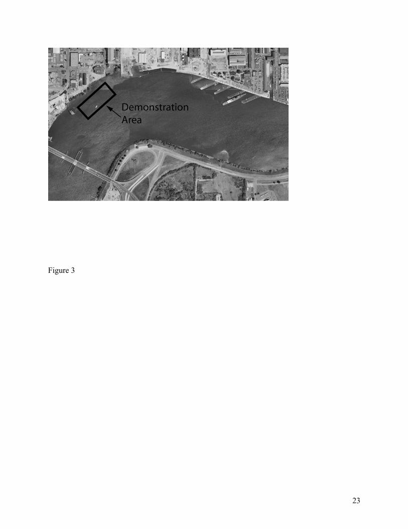
caps being evaluated in the Anacostia River Active Capping demonstration project. The

innovative caps were placed in adjacent near-shore sites in the Anacostia River between the

Washington Naval Yard and the South Capitol Street Bridge (Figure 3). The demonstration site

was chosen because it was outside of the navigational channel, was a slow flow segment of the

river, and had a minimal slope (<4%). The median flow velocity was 0.04 m/s (high slack) to

0.06 m/s (maximum flood) with a max of 0.2 m/s to 0.4 m/s at high slack and maximum flood,

respectively, and a minimum of 0.003 m/s (Horne Engineering, 2004). The water depth (NAVD

8

88) at the demonstration site ranged from 1.1 m near the shore to 5.6 m near the navigation

channel. The RCM was placed nearer the navigation channel at a depth of 2.2 to 4.0 meters

below the surface. The sediment at the site was a 3 m layer of high plasticity silty clay which

was soft, weak, and compressible. This was underlain by 1.5 m thick layer of silty clayey sand.

Contamination at the site was extensive but low level, with PCBs ranging from 25 to 2400

µg/kg, PAHs ranging from 470 mg/kg to 82 mg/L (near the CSO outfall), and heavy metals less

than 10 mg/kg for As, Cd, and Hg. Concentrations (mg/kg) of Cr (66 ±10), Pb (470 ±80), Ni

(52±6), and Zn (630 ±90) were higher (Horne Engineering, 2004).

Using a crane with a clamshell and a diver, twelve 3.1 m x 31 m coke-filled RCMs were placed

in the Anacostia River over a three day period (Figure 4). The mats were placed with a 0.3 m

overlap to ensure good coverage between the sections. In order to visually inspect the mat for

leaching of fines, the RCM was fully saturated with water and then brought back to the barge

deck. Water dripping from the mat was clear and did not contain noticeable coke particles,

indicating that fines leaching from the mat were minimal. When the RCM was submerged,

trapped air was quickly displaced by water and it readily sunk. Once the RCM was placed on the

river bottom, a 3 m section of the RCM was unrolled by the diver and secured with a 15 cm layer

of sand placed by a clamshell. The remaining 28 m of RCM was unrolled by lifting the rolled

portion of the mat off the sediment floor (~0.5 m) and moving the crane horizontally over the

water. A diver followed the unrolling mat to insure proper placement. A sand layer (~15 cm)

was then placed above the RCM by particle broadcasting to secure it in place and provide a

habitat for benthic organisms to colonize. The RCM placement rate was approximately 100

m2/hr, not including the time to place the 15 cm sand layer over the mat.

9

During cap placement, silt screens surrounded the demonstration site to mitigate release of

suspended sediments. During cap placement, dissolved oxygen, pH, conductivity, and

temperature measurements were made inside and outside of the RCM cell, as well as outside the

silt screen at an approximate depth of 15 cm below the water surface with a Horiba U-10 water

quality meter. Turbidity and total suspended solids (TSS) were measured inside of the screen

and compared with measurements made during sand capping alone and with measurements from

outside of the screen to assess the level of sediment re-suspension during cap placement. A total

of 16 turbidity measurements were taken during placement (10 outside and 6 inside the cell). A

total of 5 TSS measurements were taken, with replicate measurements made inside the RCM cell

during placement.

Water samples within the silt curtain were collected before and during cap placement and

analyzed by Severn Trent Laboratories (Knoxville, TN) for the EPA 13 priority metals (EPA

Method 6020), mercury (EPA Method 7470a), PAHs (EPA Method 8270c), PCBs (EPA Method

1668a), and TSS (EPA Method 160.2). These test methods are documented in USEPA 1987.

At 1, 6, and 18 months after cap placement, gravity cores were taken of the sand layer above the

RCM. At the one month sampling event after cap placement, vibratory coring (Ocean Survey,

Inc.) was attempted, but the coring apparatus was unable to cut the fibrous polyester core of the

RCM. Since vibratory coring was not able to penetrate the RCM, a diver removed a 0.1 m2

section of the RCM at 6 and 18 months after cap placement, and cores were taken of the

sediment layer below the RCM. A PCB profile through the RCM was not possible because the

10

RCM was very thin (1.25 cm) and did not allow the spatial resolution necessary to generate a

concentration profile within the RCM. Instead, the coke removed from the 0.1 m2 section of

RCM was homogenized and analyzed for PCBs to estimate the flux of PCBs from the sediment

into the RCM. Severn Trent Laboratories (Knoxville, TN) soxhlet extracted PCBs and PAHs

from the sand, sediment and coke (EPA Method 3540c) and used a gas chromatograph to analyze

the extracts for PCBs (EPA Method 8082) and PAHs (EPA Method 8270c). These test methods

are documented in USEPA 1987.

Results and Discussion

Water quality monitoring was performed during cap placement during the two days of the

reactive core mat placement. The pH in the cell ranged from 7.0 (precapping) to 7.25 (post

capping) in the center of the RCM cell, while the pH measured outside the cell was steady at

7.27 ±0.01. Dissolved oxygen ranged from 8.1 mg/L to 8.7 mg/L in the center of the cell during

RCM placement, and ranged from 8.3 mg/L to 9.4 mg/L outside the cell. Specific conductance

was 0.32 ±0.01 both inside and outside the cell. The water temperature (11.5 °C in the morning

and increasing to 12 °C in the afternoon) and salinity (0.01%) was the same inside and outside

the cell. Thus, pH, conductivity, dissolved oxygen, temperature, and salinity were not

significantly affected by RCM placement activities.

Water samples were collected before and during sand cap and RCM placement to evaluate the

potential for contaminated sediment re-suspension and thus river water contamination. The

water samples were analyzed for 13 metals and mercury, PCBs, PAHs, and TSS. Cr, Cu, Pb, Ni,

and Zn were detected in water samples (all less than 8 µg/L) during cap placement, but these

11

values were not statistically higher than those measured for pre-cap conditions. Naphthalene (≤2

µg/L) was detected inside the RCM cell during placement, but was non-detect outside the cell.

All other PAHs were non-detect or present at less than 1 µg/L and not statistically different than

outside the RCM cell. PCB congener (57 congeners) concentrations in water samples taken

inside and outside the silt curtain during RCM placement were detectable (MDL is

approximately 0.01 ng/L), but not statistically different. Table 2 shows the results of the TSS

analysis and turbidity data. As Table 2 shows there were less TSS in the RCM cell (17.8) than in

the sand cap cell (28.8) during placement. In general, the surface water results indicated that

during RCM placement sediment re-suspension was minimal, and that there was not a significant

difference in water quality during the placement of the sand cap and RCM.

Gravity cores of the sand layer above the RCM were taken at three locations and analyzed for

PCBs at the sand-RCM interface, and at the sand-water column interface to assess the cap

placement effectiveness, and the cap’s ability to mitigate PCB flux from the underlying

sediment. No detectable PCBs were found at the sand-RCM interface, indicating that PCBs have

not broken through the RCM in the 18 months after placement. This is consistent with model

simulations of a coke-filled RCM showing that decades (at a minimum) are needed before PCBs

would move through the 1.25-cm coke layer (Murphy et al., 2006). Over time, some PCBs were

detected at the sand-water column interface exhibiting no continuity to contaminants in the

underlying sediment or cap layer. Total PCB concentrations were 0.5 mg/kg, 0.4 mg/kg, and 1.4

mg/kg in the top 2 centimeters of the sand cap at the three sand-water column interface locations

measured. The sand-water column interfacial contamination was presumably due to deposition

of contaminated sediments from elsewhere since no source control efforts were part of the

12

demonstration project. The coke from the RCM sampled by a diver after 18 months had

undetectable levels of all PCB congeners. These data indicate that enough time has not passed

for significant PCB mass to transport into the RCM.

Using an ultrasonic seepage meter, seepage data were collected before and after placement of the

RCM to assess the effect of the cap on site hydrology. Data were collected for a 24 hour period

starting on September 9th, 2003 and ending on September 10th, 2003 and the average specific

discharge was 4.7 cm/d (upwelling from the sediment) with a minimum and maximum of 3.0 and

6.0 cm/day respectively (Matrix Environmental and Geotechnical Services, 2003). The RCM

was installed in April, 2004 and approximately 6 months after the RCM was installed (October

4th, 2004 to October 7th, 2004), seepage data were again collected and the average specific

discharge was 6.7 cm/day with a minimum and maximum of 4.3 and 8.3 cm/day respectively

(Matrix Environmental and Geotechnical Services, 2005). As these data indicate, there was no

apparent reduction in hydraulic conductivity and seepage due to the placement of the RCM. This

is in contrast the Aquablock™ cap where the seepage was reduced to ~0 after placement of this

clay-based material designed to provide an impermeable cap that eliminates groundwater

upwelling through sediments.

The total installed cost (including materials, labor, etc.) for the RCM was not determined

independently for this demonstration project. Typical costs of large scale cap applications,

however, are approximately $17-$21/m2 plus the cost of materials (Reible, 2004). The material

and construction costs for the coke-filled RCM were approximately $12/m2, making the overall

placement cost in the range of $29-33/m2. The materials cost would change depending on the

13

type of sorbent and geotextile used, but a materials cost of $10-20/m2 should be expected. By

increasing the size of each RCM section, the placement rate would be higher and the overall

installation costs could be lower.

Conclusions

Sorbent-filled geotextiles, or RCMs, offer the ability to accurately deliver thin (1.25 cm) layers

of low density sorbents to sediment capping systems. A crane and diver rapidly placed a RCM

(~100 m2/hr) over river sediments. Sediment re-suspension during placement was minimal and

comparable to that observed for placing sand caps and to background re-suspension in the river.

Water samples taken before and during RCM and sand cap placement showed that water quality

was not impacted due to cap placement. Seepage data indicated there was no significant change

in site hydrology due to the placement of the RCM.

Future studies are required to identify and better understand the dominant physical and chemical

processes controlling the rate of contaminant transport through the in place RCM so its

properties can be optimized for specific site conditions. Sorbents can be tailored to mitigate the

flux of specific contaminants and reactive media can be engineered to degrade or detoxify

contaminants as they migrate through the reactive cap layer. Microbial colonization and

selective biofilm growth within a cap may also provide opportunities for in-situ biodegradation

of contaminants. The ability to accurately place thin layers of cap materials makes it possible to

consider more expensive sorbents or reactive media in engineered caps, provided that their

enhanced performance justifies their higher cost. Continued work at the Anacostia and other cap

demonstration sites must also address ISC design concerns including initial habitat loss and

14

habitat recolonization rates, cap and sediment consolidation, cap permeability to gases generated

in the underlying sediments, and the long-term structural integrity of the cap.

Acknowledgements

This work was funded by the Hazardous Substance Research Center-SSW (R139634), the

Cooperative Institute for Coastal and Estuarine Environmental Technology (CICEET), and by

Alcoa, Inc. (Pittsburgh, PA). The authors also thank the reviewers for their insightful comments

that significantly improved the quality of this manuscript.

References

Alcoa, Inc. (2003). “2002 capping pilot study monitoring program - Summary report, Grasse

River study area,” Massena, NY.

Bott T. L. and Stanley, L. J. 2000. Transfer of Benzo[a]pyrene and 2,2',5,5'-Tetrachlorobiphenyl

from Bacteria and Algae to Sediment-Associated Freshwater Invertebrates. Environ. Sci.

Technol. 34 4936-4942.

Constants, W.D., Reible, D.D., and Bates, J. L. 2005. Field Demonstration of Active Caps:

Innovative Capping and In-Situ Treatment Technologies, Project Status Report April, 2004 to

March, 2005. Hazardous Substance Research Center South/Southwest, Louisiana State

University, Baton Rouge, LA, available online at http://www.hsrc.org/hsrc/html/ssw/ana-

reports.html.

15

Fleischer, P. and Heibaum, M. 2002. Installation of clay geosynthetic barriers under water –

three years of experience. Clay Geosynthetic Barriers: Proceedings of the International

Symposium, Nuremberg, Germany, 16-17 April.

Ghosh, U., Talley, J.W., and Luthy, R.G. 2001. Particle scale desorption kinetics and

thermodynamics from sediment. Environ. Sci. Technol., 35, 3468-3475.

Horne Engineering Services, Inc., 2004. Revised Draft Cap Completion Report for Comparative

Validation of Innovative “Active Capping” Technologies Anacostia River Washington, D.C.

Falls Church, VA, available online at http://www.hsrc.org/hsrc/html/ssw/ana-reports.html.

Jonker, M.T.O. and Koelmans, A.A. 2002. Sorption of polycyclic aromatic hydrocarbons and

polychlorinated biphenyls to soot and soot-like materials in the aqueous environment:

mechanistic considerations. Environ. Sci. Technol., 36, 3725-3734.

Kleineidam, S., Schuth, C., and Grathwohl, P. 2002. Solubility-normalized combined

adsorption-partitioning sorption isotherms for organic pollutants. Environ. Sci. Technol., 36,

4689-4697.

Matrix Environmental and Geotechnical Services. 2003. Quantifying Specific Discharge Across

the Sediment – Water Interface Within A Test Area of the Anacostia River, Washington, D.C.

A Pre-Capping Evaluation. Florham Park, NJ.

16

Matrix Environmental and Geotechnical Services. 2005. Quantifying Specific Discharge Across

the Sediment – Water Interface Within A Test Area of the Anacostia River, Washington, D.C.

Month 6 Post-Capping Evaluation, Draft Report, February, 2005. East Hanover, NJ.

Mcleod, P., van den Huevel-Greve, M., Allen-king, R., Luoma, S., and Luthy, R. 2004. Effects

of particulate carbonaceous matter on the bioavailability of benzo[a]pyrene and 2,2’,5,5’-

tetrachlorobiphenyl to the clam, Macroma balthica.” Environ. Sci. Technol., 38, 4549-4556.

Murphy, P., Marquette, A., Reible, D., Lowry, G. 2006. “Predicting the Performance of

Activated Carbon-, Coke-, and Soil-amended Thin Layer Sediment Caps”, J. Environ. Eng.

132, 787-794.

Palermo, M., Maynord, S., Miller, J., and Reible, D. 1998. Guidance for in-situ subaqueous

capping of contaminated sediments. EPA 905-B96-004, Great Lakes National Program Office,

Chicago, IL.

Reible, D.D., D. Hayes, C. Lue-Hing, J. Patterson, N. Bhowmik, M. Johnson, and J.Teal. 2003.

Comparison of the long-term risks of removal and in-situ management of contaminated

sediments in the Fox River. J. Soil Sed. Contam., 12 325-344.

Reible, D.D. 2004. Cost and Feasibility of Conventional and Active Sediment Capping.

Presented at the Technology Benchmarking Workshop For Sediment and Floodplain

Remediation, Ann Arbor, MI, March 25-26, 2004.

17

Talbert, B., Thibodeaux, L., and Valsaraj, V. 2001. Effectiveness of very thin soil layers in

chemical release from bed sediment. Environmental Progress, 20 103-107.

Talley, J. W., Ghosh, U, Tucker, S.G., Furey, J.S., and Luthy, R.G. 2002. Particle-scale

understanding of the bioavailability of PAHs in sediment. Environ. Sci. Technol., 36 477-483.

United States Environmental Protection Agency (USEPA), 1987. “Test Methods for Evaluating

Solid Waste: Physical/Chemical Methods”, Third Edition.

Zimmerman, J., Ghosh, U., Millward, R., Bridges, T., and Luthy, R. 2004. Addition of carbon

sorbents to reduce PCB and PAH bioavailability in marine sediments: Physicochemical tests.

Environ. Sci. Technol., 38 5458-5464.

18

Table 1. Innovative Sediment Caps Installed or Planned.

Cap Type Contaminant or Purpose Location

Apatite/sand

AquaBlock/sand

Coke/sand

Sequester heavy metals

Hydraulic control

Sequester PCBs and PAHs

Anacostia River,

Washington DC

AquaBlock Evaluate installation

techniques

Ottawa River, OH

AquaBlock Evaluate installation

techniques

Fort Richardson, AK

Activated Carbon-RCMa Sequester PAHs Stryker Bay, Duluth MN

Organoclay-bulk and in RCM Contain creosote NAPL Portland, OR

Sand/topsoil-30 cm

Granular bentonite

Sand/soil/bentonite slurry

Aquablock

Contain PCBs

Grasse River, Massena NY

(Alcoa, 2003)

a. Planned but not yet installed.

19

Table 2. Total suspended solids and turbidity results from water quality samples taken before

and during sand cap and reactive core mat placement in the Anacostia Rivera

Sampling Event

Total Susp. Solids

(mg/l)

Turbidity

(NTU)

Precappingb 28.4 N/A

Average Median Std.

Dev.

Sand Cap Placement

Inside cell above cap during placement 28.8 38 49 45

Outside cell during placement 24.8 31 28 37

RCM Placement

Inside cell above cap during placement 17.8 ±1.4c 48 23 48

Outside cell during placement 26.0 45 20 67

a Source: Horne Engineering Services, Inc., 2004

b Water sample was taken after the silt curtain was placed in the river but before any capping

installation work began

c Average and standard deviation of two samples taken at different times during placement.

20

Figure Captions

Figure 1. The proposed design for sorbent-amended sediment caps. A thin layer of sorbent to

sequester contaminants or material to degrade or transform contaminants is overlain with a sand

layer. The choice of materials for the overlying layer may be used to select for specific benthic

organisms and aquatic plants.

Figure 2. A section of a coke-filled reactive core mat. The coke layer was 1.25-cm thick with a

coke density of 24 kg/m2.

Figure 3. Location of the Active Capping demonstration project in the Anacostia River.

Innovative caps containing apatite for sequestering heavy metals, coke for sequestering PCBs

and PAHs, and aquablock for hydraulic control were placed here in March and April, 2004.

Figure 4. A reactive core mat on a stinger bar attached to clamshell being placed in the

Anacostia River during the Anacostia River Active Capping demonstration project, April, 2004.

21

Figure 1

Contaminated Sediment

Sorbent Layer

Sand Layer

Benthic Zone 10 +/- 5 cm

Surface Water

22

Figure 2

23

Figure 3

24

Figure 4


Recommended