Contract No. SEWERAGE SYSTEM C:\Documents and Settings\Adam\Desktop\LATM\C402.DOC (2 March, 1999) AUSPEC-1\C402 - February 97 (Copyright SWR-TM) C402-1 Hastings_Council - Ed 2 DEVELOPMENT CONSTRUCTION SPECIFICATION C402 SEWERAGE SYSTEM Return to Contents .
Transcript
Contract No. SEWERAGE SYSTEM
C:\Documents and Settings\Adam\Desktop\LATM\C402.DOC (2 March, 1999) AUSPEC-1\C402 - February 97 (Copyright SWR-TM) C402-1
Hastings_Council - Ed 2
DEVELOPMENT CONSTRUCTION SPECIFICATION
C402 SEWERAGE SYSTEM
Return to Contents.
Contract No. SEWERAGE SYSTEM
C:\Documents and Settings\Adam\Desktop\LATM\C402.DOC (2 March, 1999) AUSPEC-1\C402 - February 97 (Copyright SWR-TM) C402-2
Hastings_Council - Ed 2
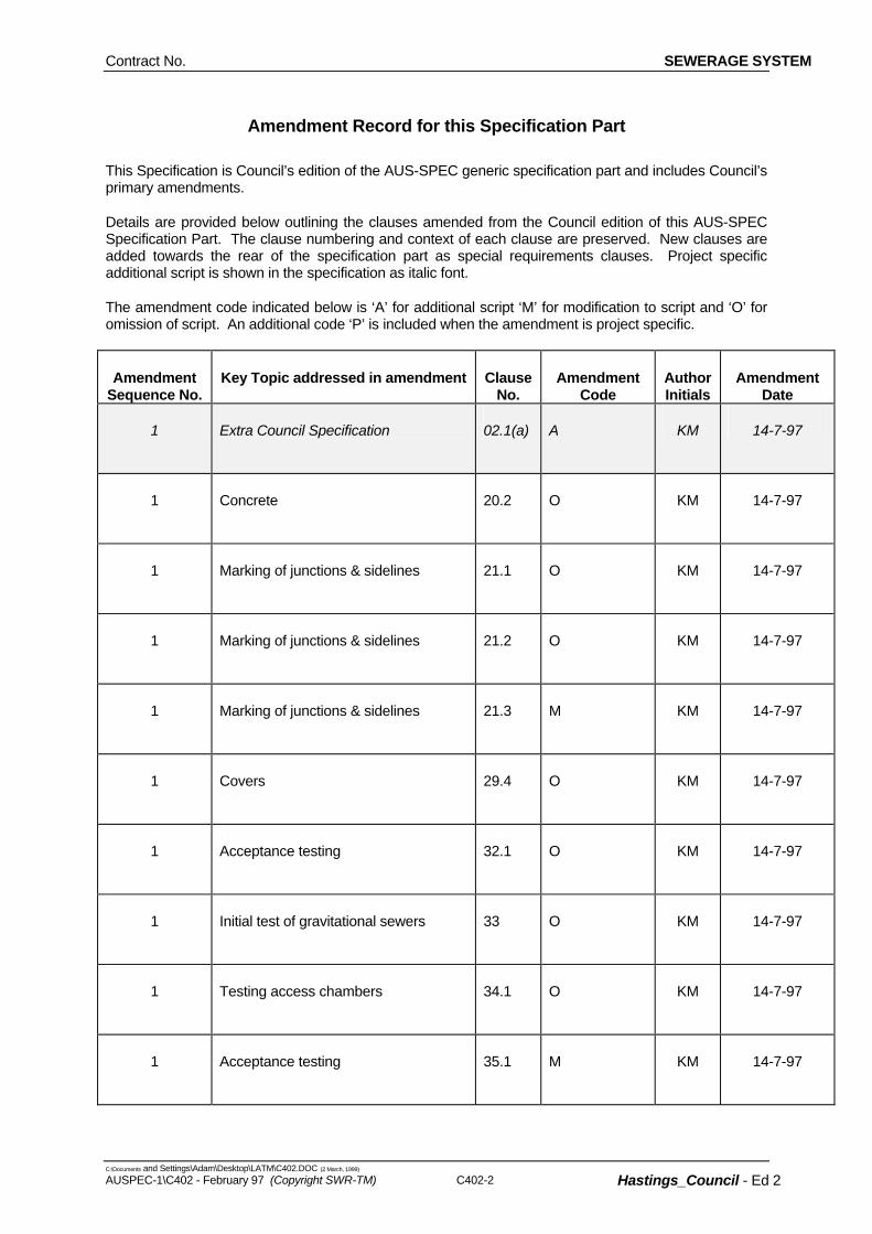
Amendment Record for this Specification Part
This Specification is Council’s edition of the AUS-SPEC generic specification part and includes Council’s primary amendments.
Details are provided below outlining the clauses amended from the Council edition of this AUS-SPEC Specification Part. The clause numbering and context of each clause are preserved. New clauses are added towards the rear of the specification part as special requirements clauses. Project specific additional script is shown in the specification as italic font.
The amendment code indicated below is ‘A’ for additional script ‘M’ for modification to script and ‘O’ for omission of script. An additional code ‘P’ is included when the amendment is project specific.
Amendment Sequence No.
Key Topic addressed in amendment Clause No.
Amendment Code
Author Initials
Amendment Date
1 Extra Council Specification
02.1(a) A KM 14-7-97
1 Concrete
20.2 O KM 14-7-97
1 Marking of junctions & sidelines
21.1 O KM 14-7-97
1 Marking of junctions & sidelines
21.2 O KM 14-7-97
1 Marking of junctions & sidelines
21.3 M KM 14-7-97
1 Covers
29.4 O KM 14-7-97
1 Acceptance testing
32.1 O KM 14-7-97
1 Initial test of gravitational sewers
33 O KM 14-7-97
1 Testing access chambers
34.1 O KM 14-7-97
1 Acceptance testing
35.1 M KM 14-7-97
SEWERAGE SYSTEM Contract No.
C:\Documents and Settings\Adam\Desktop\LATM\C402.DOC (2 March, 1999)
AUSPEC-1\C402 - February 97 (Copyright SWR-TM) Hastings_Council - Ed 2
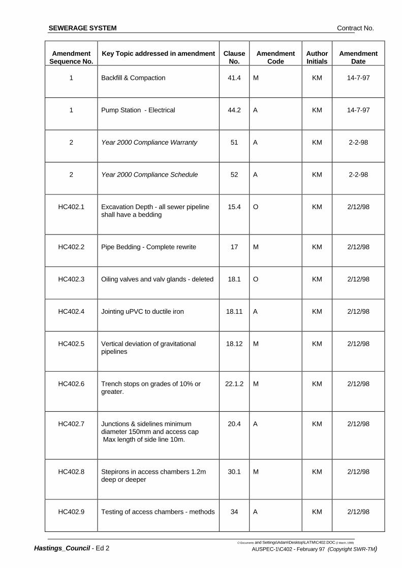
Amendment Sequence No.
Key Topic addressed in amendment Clause No.
Amendment Code
Author Initials
Amendment Date
1 Backfill & Compaction
41.4 M KM 14-7-97
1 Pump Station - Electrical
44.2 A KM 14-7-97
2 Year 2000 Compliance Warranty
51 A KM 2-2-98
2 Year 2000 Compliance Schedule
52 A KM 2-2-98
HC402.1 Excavation Depth - all sewer pipeline shall have a bedding
15.4 O KM 2/12/98
HC402.2 Pipe Bedding - Complete rewrite
17 M KM 2/12/98
HC402.3 Oiling valves and valv glands - deleted
18.1 O KM 2/12/98
HC402.4 Jointing uPVC to ductile iron
18.11 A KM 2/12/98
HC402.5 Vertical deviation of gravitational pipelines
18.12 M KM 2/12/98
HC402.6 Trench stops on grades of 10% or greater.
22.1.2 M KM 2/12/98
HC402.7 Junctions & sidelines minimum diameter 150mm and access cap Max length of side line 10m.
20.4 A KM 2/12/98
HC402.8 Stepirons in access chambers 1.2m deep or deeper
30.1 M KM 2/12/98
HC402.9 Testing of access chambers - methods
34 A KM 2/12/98
SEWERAGE SYSTEM Contract No.
C:\Documents and Settings\Adam\Desktop\LATM\C402.DOC (2 March, 1999) AUSPEC-1\C402 - February 97 (Copyright SWR-TM) C402-4
Hastings_Council - Ed 2
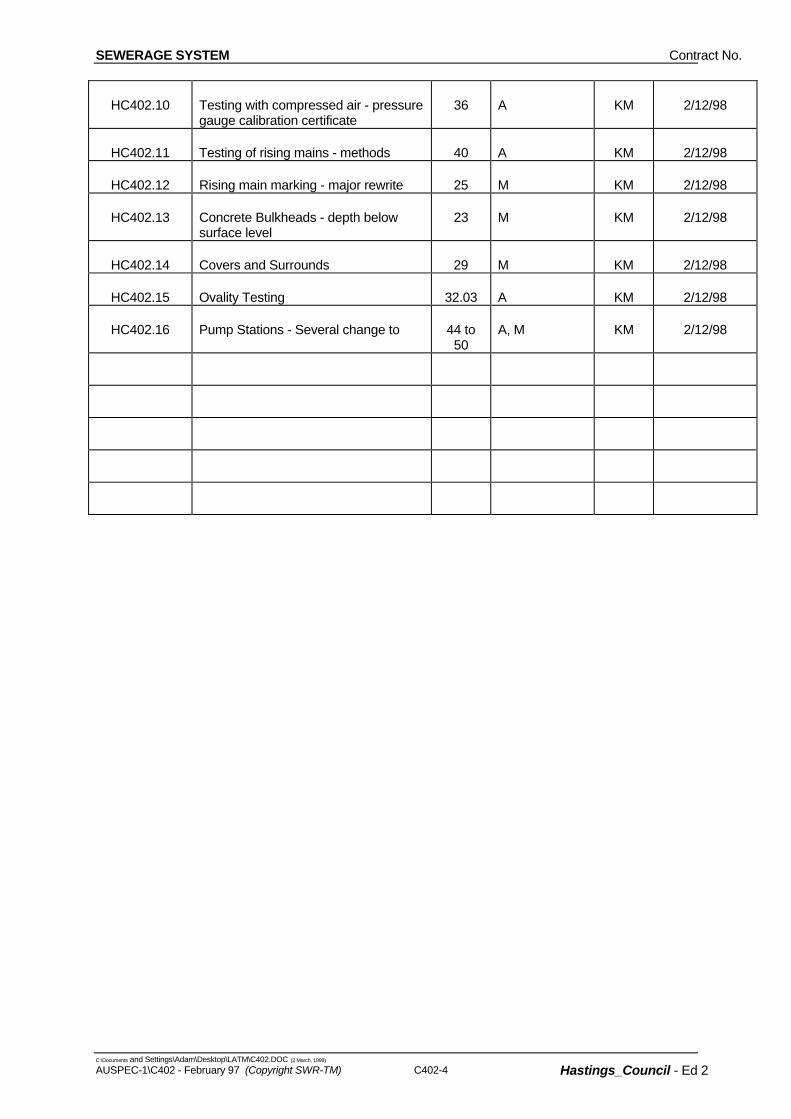
HC402.10 Testing with compressed air - pressure gauge calibration certificate
36 A KM 2/12/98
HC402.11 Testing of rising mains - methods 40 A KM 2/12/98
HC402.12 Rising main marking - major rewrite 25 M KM 2/12/98
HC402.16 Pump Stations - Several change to 44 to 50
A, M KM 2/12/98
Contract No. SEWERAGE SYSTEM
C:\Documents and Settings\Adam\Desktop\LATM\C402.DOC (2 March, 1999) AUSPEC-1\C402 - February 97 (Copyright SWR-TM) C402-1 Hastings_Council - Ed 2
AS 3439 - Low-voltage switchgear and controlgrear assemblies.
SPECIFICATION C402 : SEWERAGE SYSTEM
GENERAL
C402.01 SCOPE
1. This Specification applies to the construction of:
• gravitation sewers up to DN600 nominal size;
• rising mains up to DN600 nominal size;
• standard appurtenances such as access chambers and sidelines;
• pumping stations.
C402.02 REFERENCE DOCUMENTS
1. Documents referenced in this specification are listed in full below whilst being cited in the text in the abbreviated form or code indicated.
Documents Standards Test Methods
(a) Council Specification C271 - Minor Concrete Works Hastings Council - Minor Sewerage Pumping Station Requirements (Aug 1992)
(b) Australian Standards AS 1214 - Hot-dip galvanized coating on threaded fasteners AS 1260 - Unplasticized PVC (uPVC), pipes and fittings for sewerage
applications. AS 1289.5.7.1 - Compaction control test (Rapid method). AS 1444 - Wrought alloy steels - Standard and hardenability (H) series. AS1477 - Unplasticized PVC (uPVC) pipes and fittings for pressure
applications AS 1565 - Copper and copper alloys - Ingots and castings. AS 1627 - Metal finishing - Preparation and pretreatment of surfaces AS 1646 - Elastomeric seals for waterworks purposes. AS 1650 - Hot-dipped galvanized coatings on ferrous articles. AS 1657 Fixed platforms, walkways, stairways and ladders. AS 1741 - Vitrified clay pipes and fittings with flexible joints - Sewer
quality. AS 1830 - Iron castings - Grey cast iron. AS 1939 - Degrees of protection provided by enclosures for electrical
equipment AS 2032 - Code of practice for installation of uPVC pipe systems. AS 2129 - Flanges for pipes, valves and fittings. AS/NZS 2280 - Ductile iron pressure pipe and fittings. AS2865 Safe working in a confined space AS 3000 - Electrical installations (SAA Wiring Rules).
AS3500 National Plumbing and Drainage Code AS 3972 - Portland and blended cements. AS 4060 - Loads on buried vitrified clay pipes. AS 4198 - Precast concrete access chambers for sewerage
applications.
SEWERAGE SYSTEM Contract No.
C:\Documents and Settings\Adam\Desktop\LATM\C402.DOC (2 March, 1999)
C402-2 AUSPEC-1\C402 - February 97 (Copyright SWR-TM)
Hastings_Council - Ed 2
1. Cast iron access chamber covers and frames shall be “Gatic” or approved equivalent suitable for concrete filling. The type shall be as shown on the Drawings.
Installations) PWD-SD Public Works Department Manual of Practice - Sewer Design. AWSSA - Australian Water Supply and Sewerage Authorities
Specification of Technical Requirement
MATERIALS
C402.03 UNPLASTICISED PVC
1. Unplasticised PVC (uPVC) pipes and fittings for gravity systems shall be manufactured in accordance with AS1260 suitable for rubber ring joints.
Non-pressure Pipe
2. Where non-pressure pipe is laid at a depth greater than 3 metres from the finished ground level to pipe invert, class SEH pipe (including Ultra Rib) shall be used. Class SH maybe used elsewhere.
3. Unplasticised PVC (uPVC) pipes and fittings for rising mains and suction pipes shall be manufactured in accordance with AS1477 Class 12 suitable for rubber ring joints.
Pressure Pipe
4. Rubber rings shall comply with AS1646. Rubber Rings
C402.04 DUCTILE IRON
1. Ductile iron (DI) pipes and fittings shall be manufactured in accordance with AS/NZS 2280 Class K9 suitable for the patented “Tyton” type rubber ring joint.
Standard
2. Flanges shall comply with AS2129 Table D. Bolts and nuts for flanged joints shall be in accordance with AS2129 and galvanised in accordance with AS1214.
Flanges
3. The type of external corrosion protection of buried pipelines shall be as shown on the Drawings.
Corrosion Protection
C402.05 VITRIFIED CLAY
1. Vitrified clay (VC) pipes and fittings shall be manufactured in accordance with AS1741 for the class of pipe complying with the loading requirements of AS 4060.
Standard
2. Rubber ring joints shall comply with AS1741. Rubber Rings
C402.06 PRECAST ACCESS CHAMBERS
1. Precast access chambers components shall comply with AS 4198.
C402.07 ACCESS CHAMBER COVERS
Cast Iron
2. Heavy type conrete covers shall be used shall be used on allaccess chambers located in a trafficable area or if the diametre of any pipe into, or out of, the chamber has a
Concrete Covers
Contract No. SEWERAGE SYSTEM
C:\Documents and Settings\Adam\Desktop\LATM\C402.DOC (2 March, 1999) AUSPEC-1\C402 - February 97 (Copyright SWR-TM) C402-3 Hastings_Council - Ed 2
diametre greater than or equal to 225mm. Light type concrete covers may be used elsewhere unless shown otherwise in the Drawings.
C402.08 STEELWORK
1. Structural steelwork, ladders, brackets, covers etc shall be abrasive blast cleaned to AS1627 Class 3 and hot dip galvanised to AS1650.
Corrosion Protection
PIPELINE CONSTRUCTION
C402.09 LOCATION
1. The location of the sewers, access chambers, rising mains and pumping stations, sizes and grades of sewers and rising mains, the types of access chambers and access chamber covers and the classes of pipes are shown on the Drawings. Laying of pipelines shall commence at the lower end of the line unless directed otherwise by the Superintendent. The pipelines shall be laid to grades and locations shown on the Drawings unless directed otherwise by the Superintendent.
General
C402.10 COVER OVER PIPELINES
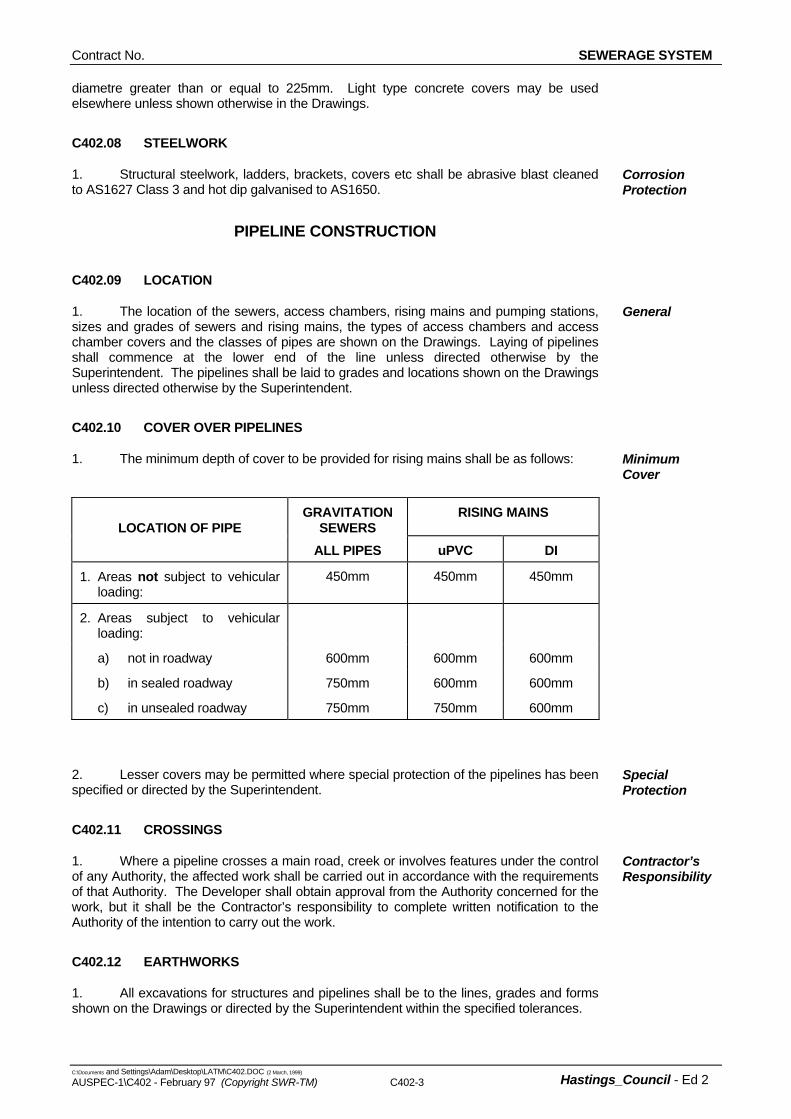
1. The minimum depth of cover to be provided for rising mains shall be as follows: Minimum Cover
LOCATION OF PIPE
GRAVITATION SEWERS
RISING MAINS
ALL PIPES uPVC DI
1. Areas not subject to vehicular loading:
450mm 450mm 450mm
2. Areas subject to vehicular loading:
a) not in roadway 600mm 600mm 600mm
b) in sealed roadway 750mm 600mm 600mm
c) in unsealed roadway 750mm 750mm 600mm
2. Lesser covers may be permitted where special protection of the pipelines has been specified or directed by the Superintendent.
Special Protection
C402.11 CROSSINGS
1. Where a pipeline crosses a main road, creek or involves features under the control of any Authority, the affected work shall be carried out in accordance with the requirements of that Authority. The Developer shall obtain approval from the Authority concerned for the work, but it shall be the Contractor’s responsibility to complete written notification to the Authority of the intention to carry out the work.
Contractor’s Responsibility
C402.12 EARTHWORKS
1. All excavations for structures and pipelines shall be to the lines, grades and forms shown on the Drawings or directed by the Superintendent within the specified tolerances.
SEWERAGE SYSTEM Contract No.
C:\Documents and Settings\Adam\Desktop\LATM\C402.DOC (2 March, 1999)
C402-4 AUSPEC-1\C402 - February 97 (Copyright SWR-TM)
Hastings_Council - Ed 2
2. The Contractor shall leave a clear space of 600mm minimum between the edge of any excavation and the inner toe of spoil banks. No excavated materials shall be stacked against the walls of any building or fence without the written permission of the owner of such building or fence. Topsoil from excavations shall be kept separate and utilised to make good the surface after backfilling.
Excavated Material
3. At completion of work each day, safety fencing shall be installed along edges of open excavations to isolate them from the public. Where necessary, fenced walkways and vehicular crossways shall be provided across trenches to maintain access from carriageway to individual properties or within individual properties. All such installations shall be of adequate size and strength and satisfactorily illuminated.
Public Safety
C402.13 MINIMUM TRENCH WIDTH FOR PIPELINES
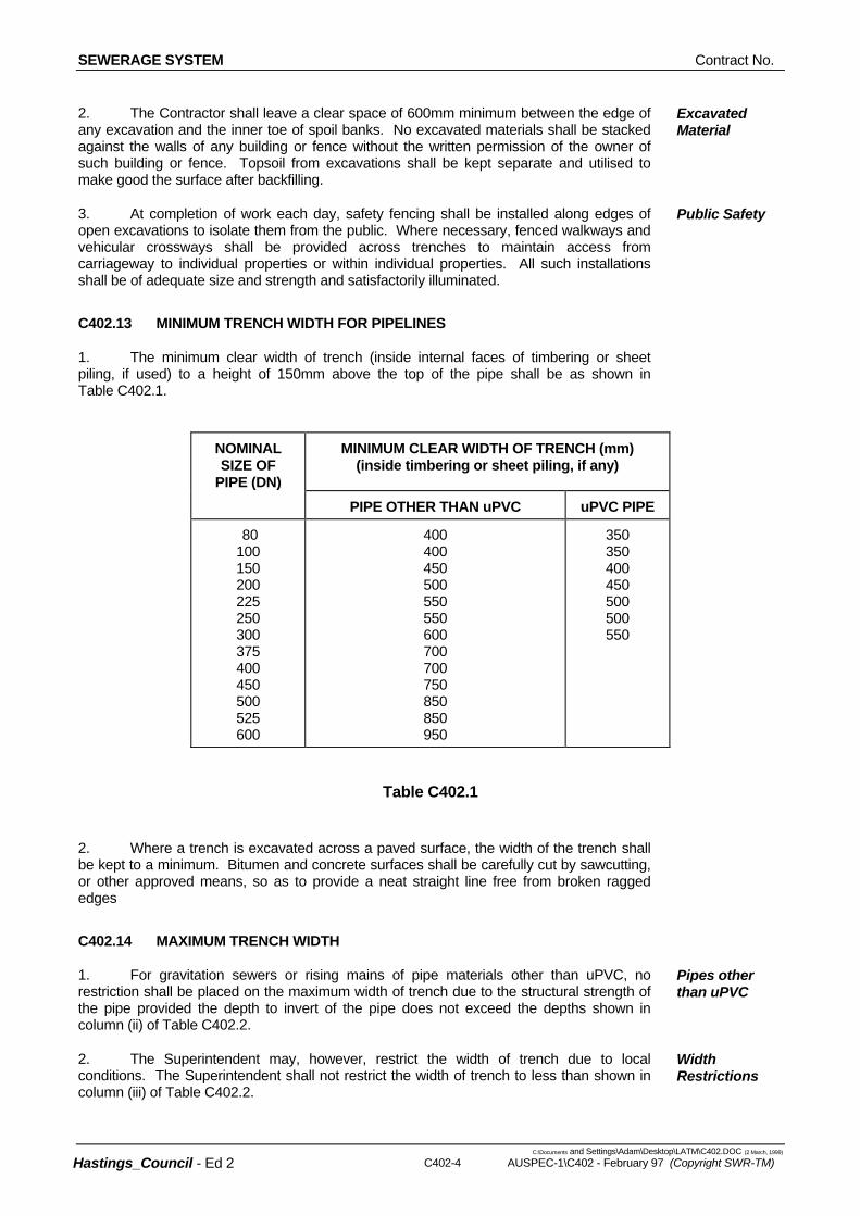
1. The minimum clear width of trench (inside internal faces of timbering or sheet piling, if used) to a height of 150mm above the top of the pipe shall be as shown in Table C402.1.
NOMINAL SIZE OF
PIPE (DN)
MINIMUM CLEAR WIDTH OF TRENCH (mm) (inside timbering or sheet piling, if any)
2. Where a trench is excavated across a paved surface, the width of the trench shall be kept to a minimum. Bitumen and concrete surfaces shall be carefully cut by sawcutting, or other approved means, so as to provide a neat straight line free from broken ragged edges
C402.14 MAXIMUM TRENCH WIDTH
1. For gravitation sewers or rising mains of pipe materials other than uPVC, no restriction shall be placed on the maximum width of trench due to the structural strength of the pipe provided the depth to invert of the pipe does not exceed the depths shown in column (ii) of Table C402.2.
Pipes other than uPVC
2. The Superintendent may, however, restrict the width of trench due to local conditions. The Superintendent shall not restrict the width of trench to less than shown in column (iii) of Table C402.2.
Width Restrictions
Contract No. SEWERAGE SYSTEM
C:\Documents and Settings\Adam\Desktop\LATM\C402.DOC (2 March, 1999) AUSPEC-1\C402 - February 97 (Copyright SWR-TM) C402-5 Hastings_Council - Ed 2
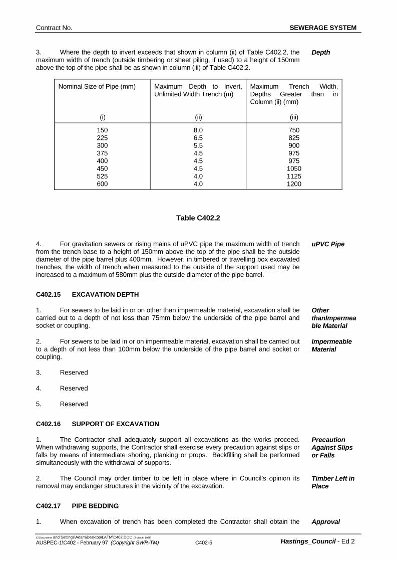
3. Where the depth to invert exceeds that shown in column (ii) of Table C402.2, the maximum width of trench (outside timbering or sheet piling, if used) to a height of 150mm above the top of the pipe shall be as shown in column (iii) of Table C402.2.
Depth
Nominal Size of Pipe (mm) (i)
Maximum Depth to Invert, Unlimited Width Trench (m) (ii)
Maximum Trench Width, Depths Greater than in Column (ii) (mm) (iii)
150 225 300 375 400 450 525 600
8.0 6.5 5.5 4.5 4.5 4.5 4.0 4.0
750 825 900 975 975 1050 1125 1200
Table C402.2
4. For gravitation sewers or rising mains of uPVC pipe the maximum width of trench from the trench base to a height of 150mm above the top of the pipe shall be the outside diameter of the pipe barrel plus 400mm. However, in timbered or travelling box excavated trenches, the width of trench when measured to the outside of the support used may be increased to a maximum of 580mm plus the outside diameter of the pipe barrel.
uPVC Pipe
C402.15 EXCAVATION DEPTH
1. For sewers to be laid in or on other than impermeable material, excavation shall be carried out to a depth of not less than 75mm below the underside of the pipe barrel and socket or coupling.
Other thanImpermeable Material
2. For sewers to be laid in or on impermeable material, excavation shall be carried out to a depth of not less than 100mm below the underside of the pipe barrel and socket or coupling.
Impermeable Material
3. Reserved
4. Reserved
5. Reserved
C402.16 SUPPORT OF EXCAVATION
1. The Contractor shall adequately support all excavations as the works proceed. When withdrawing supports, the Contractor shall exercise every precaution against slips or falls by means of intermediate shoring, planking or props. Backfilling shall be performed simultaneously with the withdrawal of supports.
Precaution Against Slips or Falls
2. The Council may order timber to be left in place where in Council’s opinion its removal may endanger structures in the vicinity of the excavation.
Timber Left in Place
C402.17 PIPE BEDDING
1. When excavation of trench has been completed the Contractor shall obtain the Approval
SEWERAGE SYSTEM Contract No.
C:\Documents and Settings\Adam\Desktop\LATM\C402.DOC (2 March, 1999)
C402-6 AUSPEC-1\C402 - February 97 (Copyright SWR-TM)
Hastings_Council - Ed 2
Superintendent’s approval prior to commencing pipe bedding.
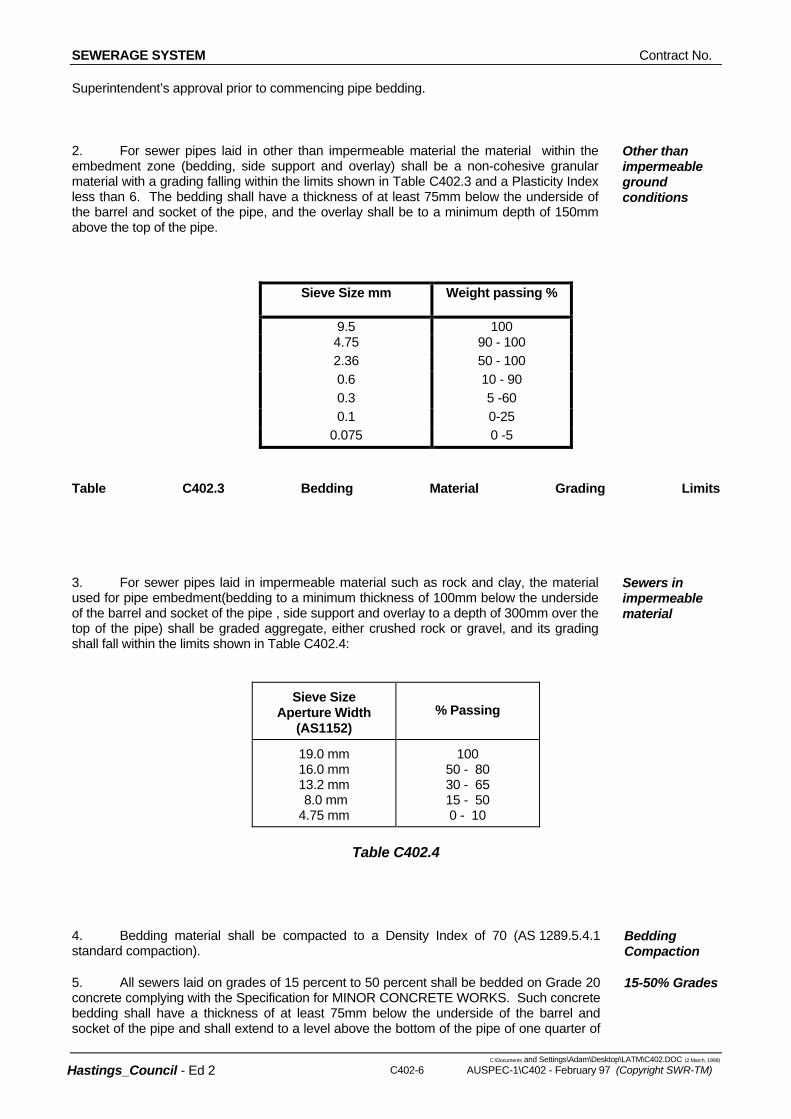
2. For sewer pipes laid in other than impermeable material the material within the embedment zone (bedding, side support and overlay) shall be a non-cohesive granular material with a grading falling within the limits shown in Table C402.3 and a Plasticity Index less than 6. The bedding shall have a thickness of at least 75mm below the underside of the barrel and socket of the pipe, and the overlay shall be to a minimum depth of 150mm above the top of the pipe.
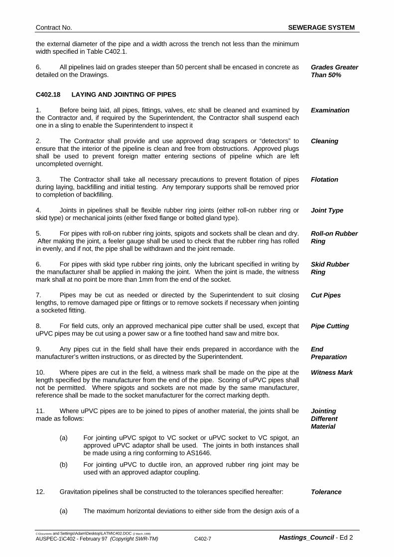
3. For sewer pipes laid in impermeable material such as rock and clay, the material used for pipe embedment(bedding to a minimum thickness of 100mm below the underside of the barrel and socket of the pipe , side support and overlay to a depth of 300mm over the top of the pipe) shall be graded aggregate, either crushed rock or gravel, and its grading shall fall within the limits shown in Table C402.4:
Sewers in impermeable material
Sieve Size Aperture Width
(AS1152)
% Passing
19.0 mm 16.0 mm 13.2 mm 8.0 mm 4.75 mm
100 50 - 80 30 - 65 15 - 50 0 - 10
Table C402.4
4. Bedding material shall be compacted to a Density Index of 70 (AS 1289.5.4.1 standard compaction).
Bedding Compaction
5. All sewers laid on grades of 15 percent to 50 percent shall be bedded on Grade 20 concrete complying with the Specification for MINOR CONCRETE WORKS. Such concrete bedding shall have a thickness of at least 75mm below the underside of the barrel and socket of the pipe and shall extend to a level above the bottom of the pipe of one quarter of
15-50% Grades
Contract No. SEWERAGE SYSTEM
C:\Documents and Settings\Adam\Desktop\LATM\C402.DOC (2 March, 1999) AUSPEC-1\C402 - February 97 (Copyright SWR-TM) C402-7 Hastings_Council - Ed 2
the external diameter of the pipe and a width across the trench not less than the minimum width specified in Table C402.1.
6. All pipelines laid on grades steeper than 50 percent shall be encased in concrete as detailed on the Drawings.
Grades Greater Than 50%
C402.18 LAYING AND JOINTING OF PIPES
1. Before being laid, all pipes, fittings, valves, etc shall be cleaned and examined by the Contractor and, if required by the Superintendent, the Contractor shall suspend each one in a sling to enable the Superintendent to inspect it
Examination
2. The Contractor shall provide and use approved drag scrapers or “detectors” to ensure that the interior of the pipeline is clean and free from obstructions. Approved plugs shall be used to prevent foreign matter entering sections of pipeline which are left uncompleted overnight.
Cleaning
3. The Contractor shall take all necessary precautions to prevent flotation of pipes during laying, backfilling and initial testing. Any temporary supports shall be removed prior to completion of backfilling.
Flotation
4. Joints in pipelines shall be flexible rubber ring joints (either roll-on rubber ring or skid type) or mechanical joints (either fixed flange or bolted gland type).
Joint Type
5. For pipes with roll-on rubber ring joints, spigots and sockets shall be clean and dry. After making the joint, a feeler gauge shall be used to check that the rubber ring has rolled in evenly, and if not, the pipe shall be withdrawn and the joint remade.
Roll-on Rubber Ring
6. For pipes with skid type rubber ring joints, only the lubricant specified in writing by the manufacturer shall be applied in making the joint. When the joint is made, the witness mark shall at no point be more than 1mm from the end of the socket.
Skid Rubber Ring
7. Pipes may be cut as needed or directed by the Superintendent to suit closing lengths, to remove damaged pipe or fittings or to remove sockets if necessary when jointing a socketed fitting.
Cut Pipes
8. For field cuts, only an approved mechanical pipe cutter shall be used, except that uPVC pipes may be cut using a power saw or a fine toothed hand saw and mitre box.
Pipe Cutting
9. Any pipes cut in the field shall have their ends prepared in accordance with the manufacturer’s written instructions, or as directed by the Superintendent.
End Preparation
10. Where pipes are cut in the field, a witness mark shall be made on the pipe at the length specified by the manufacturer from the end of the pipe. Scoring of uPVC pipes shall not be permitted. Where spigots and sockets are not made by the same manufacturer, reference shall be made to the socket manufacturer for the correct marking depth.
Witness Mark
11. Where uPVC pipes are to be joined to pipes of another material, the joints shall be made as follows:
(a) For jointing uPVC spigot to VC socket or uPVC socket to VC spigot, an approved uPVC adaptor shall be used. The joints in both instances shall be made using a ring conforming to AS1646.
(b) For jointing uPVC to ductile iron, an approved rubber ring joint may be used with an approved adaptor coupling.
Jointing Different Material
12. Gravitation pipelines shall be constructed to the tolerances specified hereafter:
(a) The maximum horizontal deviations to either side from the design axis of a
Tolerance
SEWERAGE SYSTEM Contract No.
C:\Documents and Settings\Adam\Desktop\LATM\C402.DOC (2 March, 1999)
C402-8 AUSPEC-1\C402 - February 97 (Copyright SWR-TM)
Hastings_Council - Ed 2
pipeline shall be 30mm for all sizes of pipes.
(b) For vertical deviations from the design grade of pipelines of any diameter and grade, the invert level shall not deviate from the design grade line by more than 10mm.
13. Flexibly jointed pipelines for rising mains with gradual changes in alignment or grade shall be laid with the joint being deflected after it has been made. The manufacturer’s written recommendations in respect of maximum deflection for each joint shall be complied with provided that no joint shall be deflected to such an extent as to impair its effectiveness.
Joint Deflection
14. Unless otherwise directed by the Superintendent, pipes for rising mains shall be laid on continuously rising grades from scour valve to air release valve, notwithstanding any minor irregularities in the ground surface.
Rising Main Grade
C402.19 CONNECTIONS TO ACCESS CHAMBERS AND STRUCTURES
1. Pipelines shall be connected to access chambers, structures or embedded concrete by means of 600mm long pipes such that two flexible joints are provided, the first joint being at or within 150mm of the face of the structure. Where flexible joints cannot be made with cut pipes, the Contractor shall select pipes from the various lengths provided in order to make the second joint within 300mm of the position shown on the drawings.
Flexible Joints
2. The positions of access chambers shown on the drawings are subject to final approval by the Superintendent immediately prior to construction. They may be varied to suit changes, such as erection of structures, growth of flora and installation of services. Once the final position of an access chamber has been approved, construction shall be subject to the following requirements:
Access Chamber Location
(a) For deviations from the design levels of access chambers as shown on the drawings or as directed by the Superintendent during construction, the following tolerances shall apply:
(i) Where the difference in levels between the inlet pipe and the outlet pipe in
an access chamber is 100mm or less: Pipe Tolerance Inlet - nil; + 25mm Outlet - 25mm; + nil (ii) Where the difference in levels, as above, is greater than 100mm: Pipe Tolerance Inlet - 22mm; + 25mm Outlet - 25mm; + 25mm
(b) Allowable lateral deviations from the final design position of access chambers shall be in accordance with the tolerances for horizontal deviations of pipelines as specified.
C402.20 JUNCTIONS AND SIDELINES
1. Junctions for deadends and sidelines or risers to properties to serve existing and future dwellings shall be provided in accordance with this Specification. Such junctions shall be inserted along pipelines in locations shown on the Drawings or directed by the Superintendent.
Location
2. Reserved
Contract No. SEWERAGE SYSTEM
C:\Documents and Settings\Adam\Desktop\LATM\C402.DOC (2 March, 1999) AUSPEC-1\C402 - February 97 (Copyright SWR-TM) C402-9 Hastings_Council - Ed 2
3. Except where concrete encasement is ordered by the Superintendent, backfill around risers shall be sand compacted to the top of the socket or coupling on the highest branch off the riser, for the full width of trench and for a minimum distance of 500mm upstream and downstream of the riser.
Backfill
4. All sidelines and junctions shall have a minimum diametre of 150mm and have a screwed access cap. Sidelines shall have a makimum length of 10m.
Caps
C402.21 MARKING OF JUNCTIONS AND SIDELINES
1. The position of each riser, junction or end of a sideline shall be clearly marked by the Contractor on completion of backfilling
Location
2. Reserved
3. A hardwood peg, 75x50xmin 600mm long shall be driven into the ground at the junction position. The peg shall be painted red and shall have a neatly stencilled letter ‘J’ painted thereon. The peg shall be connected to an underground identification tape as specified thereafter.
Hardwood Peg
4. The identification tape shall be tied to the junction or end of sideline and held in a vertical position during backfilling. The top end of the tape shall be spiked by the junction peg immediately upon completion of backfilling, or left flush with ground level where no peg is provided.
Tape Position
5. The identification tape shall be 75mm wide red coloured polyethylene tape with the inscription “Caution - buried sewer line”, printed in heavy black letters every 200mm (Identoline).
Identification Tape
C402.22 TRENCH STOPS
1. Where a gravitation sewer or rising main is laid on bedding at a grade of ten (10) percent or steeper, trench stops consisting of polyethylene bags of minimum thickness 0.25mm filled with clay or other approved material and sealed in an approved manner, shall be constructed as follows:
Grade 10% or Steeper
(a) At the socket side of the joint nearest to the position of a stop required in accordance with the formula hereinafter, a recess 100mm deep to suit the width of bag shall be excavated into the bottom of the trench across its full width and into both sidewalls to a level of 300mm above the top of the pipe.
(b) The polyethylene bags shall be placed around and to 300mm above the pipe so as to give close contact with the pipe and to fill the entire space between the excavated recess and the pipe. Bags shall not be placed onto sand bedding.
2. The distance between trench stops shall be determined by the following formula: D = 100, whereby G D = Distance between stops in m, G = Grade of pipe expressed in percentum.
Spacing
C402.23 CONCRETE BULKHEADS
1. Where a gravitation sewer or rising main is installed at a grade of fifteen (15) Grade 15% or
SEWERAGE SYSTEM Contract No.
C:\Documents and Settings\Adam\Desktop\LATM\C402.DOC (2 March, 1999)
C402-10 AUSPEC-1\C402 - February 97 (Copyright SWR-TM)
Hastings_Council - Ed 2
percent or steeper, concrete bulkheads of Grade 20 concrete complying with the Specification for MINOR CONCRETE WORKS, 150mm minimum thickness shall be constructed as follows:
(a) Where concrete bedding or encasement to pipe is required, the 150mm thick bulkhead shall be cast integral with the concrete bedding or encasement across the width of trench and shall be keyed into both sidewalls a minimum of 150mm in other than rock and 75mm in rock. The bulkhead shall extend to 150mm below finished surface level or to other such level as directed by the Superintendent.
(b) Where other bedding, or no bedding, is applicable, the bulkhead shall also be keyed into the bottom of the trench 150mm in other than rock and 75mm in rock for the full width of trench.
(c) A 75mm nominal diameter drain hole shall be provided in the concrete bulkhead immediately above the top of the encasement bedding or foundation and crushed rock or gravel shall be placed in and at the upstream end of the drain hole to act as a filter. The gravel shall be 10 to 20mm in size within 150mm in all directions upstream and above the invert of the drainhole beyond which another 150mm thick surround of gravel 2 to 10mm in size shall be placed.
Steeper
2. The distance between concrete bulkheads shall be determined by the following formula: D = 100, whereby G D = Distance between bulkheads in m G = Grade of pipe expressed in percentum
Spacing
C402.24 THRUST AND ANCHOR BLOCKS FOR RISING MAINS
1. Thrust and anchor blocks shall be constructed where shown on the Drawings to the dimensions depicted therein, or as otherwise directed by the Superintendent. The blocks shall be provided at valves, flexibly jointed bends, tees, enlargers and reducers or any other point where unbalanced forces resulting from internal pressures will occur.
Location
2. The Contractor shall provide permanent thrust blocks of Grade 20 concrete complying with the Specification for MINOR CONCRETE WORKS such that the thrust blocks bear against undisturbed material normal to the direction of thrust resulting from internal pressures over a bearing area not less than that directed by the Superintendent.
Thrust Blocks
3. The Contractor shall provide permanent anchor blocks of Grade 20 concrete complying with the Specification for MINOR CONCRETE WORKS of a volume not less than that directed by the Superintendent.
Anchor Blocks
4. The Contractor shall provide temporary anchorages adequate to restrain the pipe when under test. The cost of providing such anchorages shall be deemed to be included in the rates tendered for laying and jointing rising mains.
Temporary Anchorage
C402.25 RISING MAIN MARKINGS
1. All rising mains shall be topped with an appropriate identification tape. Identification Tape
2. At each bend the Contractor shall fix a marking plate in a manner and position as approved by the Superintendent. Unless otherwise specified in the drawings, in urban areas the kerb adjacent to each fitting is to be painted with two (2) coats of an approved nonslip paint coloured black. The pipe type, size, depth and off-set are to be shown on the
Marking Plates
Location
Contract No. SEWERAGE SYSTEM
C:\Documents and Settings\Adam\Desktop\LATM\C402.DOC (2 March, 1999) AUSPEC-1\C402 - February 97 (Copyright SWR-TM) C402-11 Hastings_Council - Ed 2
4. Application of the polyethylene tubing and plastic adhesive tape shall be in accordance with the manufacturer’s written instructions, and the Contractor shall take due care not to damage the tubing during its application or during the backfilling of the trench. Each pipe shall be encased in a length of tubing overlapped for a minimum of 250mm at each field joint, and the ends of each length of tubing shall be held in position with at least three circumferential turns of adhesive tape. As the polyethylene tube material covering the pipe will be loose, excess material shall be neatly drawn up around the pipe barrel, folded
marking plate.
3. Where, in the opinion of the Superintendent, the bend is located at too great a distance from any existing wall, fence, kerb face, or post, the Contractor shall fix the relevant marking plate to the top of an approved post, above the bend.
3. The post shall conform to the following requirements:
(a) The post shall be a galvanised spike with a black triangular prisim attached to the top. The marking plate shall be fixed on top of this. The post shall be 2000mm long.
(b) When installed, the post shall project 1600mm above the ground.
Post Details
4. The post shall be spiked to a depth of 400mm into ground.
5. Marking plates and posts shall be fixed as soon as practicable after each pipeline bend is installed.
Timing
C402.26 CONCRETE ENCASEMENT
1. Where pipes in gravity sewers or rising mains have less than 450mm of cover above the top of the pipe barrel and also where directed by the Superintendent, they shall be encased in concrete. Concrete shall be of Grade 20 complying with the Specification for MINOR CONCRETE WORKS and have the following minimum dimensions:
(a) For trenches in other than rock: 150mm minimum under, on both sides and on top of the pipe barrel.
(b) For trenches in rock: 100mm minimum under the pipe barrel, 150mm on top of the pipe barrel and for the full width of trench excavated.
Location
2. In trenches of other than rock or fissured rock, a contraction joint consisting of a layer of bituminous felt 12mm thick shall be formed in the concrete encasement at the face of each socket or at one face of each coupling.
Contraction Joint
3. Reinforcement in concrete encasement shall be as shown on the Drawings. Reinforcement
C402.27 WRAPPING OF PIPELINES
1. Where specified or directed by the Superintendent, the Contractor shall enclose a pipeline or a section thereof, in layflat polyethylene tubing.
2. The materials to be used shall be high impact resistance polyethylene tubing, such as “Zendel E.H.I.” and 50mm wide plastic adhesive tape, such as “504 Sellotape”, which shall have the ability to bond to metal surfaces and to the polyethylene material.
Material
3. The minimum thickness of the polyethylene film shall be 0.2mm, and the width of the tube when flat shall be in accordance with the manufacturer’s written recommendations for the size and type of the pipeline which is to be encased. Where the tube is to be exposed to ultra-violet light (eg sunlight) for more than 48 hours, black pigmented polyethylene shall be used; alternatively, precautions shall be taken so that exposure to direct sunlight does not exceed 48 hours.
Type
Application
SEWERAGE SYSTEM Contract No.
C:\Documents and Settings\Adam\Desktop\LATM\C402.DOC (2 March, 1999)
C402-12 AUSPEC-1\C402 - February 97 (Copyright SWR-TM)
Hastings_Council - Ed 2
into an overlap on top of the pipe and held in place by means of strips of plastic tape at approximately one metre intervals. Bends, tapers and similar fittings shall be covered by polyethylene tubing as specified for the pipes. Valves, hydrants and irregular shaped fittings shall be hand wrapped using flat polyethylene sheets secured with plastic adhesive tape to provide an adequate seal. The flat polyethylene sheets may be obtained by splitting suitable lengths of tubing.
5. Any damage done to the polyethylene tubing before, during or after backfilling of the trench shall be made good by the Contractor to the satisfaction of the Superintendent.
Damage
C402.28 CAST-IN-SITU ACCESS CHAMBERS
1. For all access chambers concrete work, the Contractor shall comply with the Specification for MINOR CONCRETE WORKS in relation to the supply and placement of concrete and steel reinforcement, formwork, tolerances, construction joints, curing and protection except as specified below.
2. Cement used in all concrete shall meet the Type SR requirements to AS 3972. Cement Type
3. The minimum cement content shall be 360 kg/m3 of concrete and the Water/Cement ratio of the mix shall not be greater than 0.50 by mass.
Minimum Cement Content
C402.29 COVERS AND SURROUNDS
1. Covers and surrounds shall not be warped or twisted. Surfaces shall be finished such that there are no abrupt irregularities and gradual irregularities shall not exceed 3mm. Unformed surfaces shall be finished by approved methods to produce a surface that is dense, uniform and free from blemishes. Exposed edges shall have a minimum 4mm radius.
2. Tolerances for the dimensions on the COVER shall be - 3mm + NIL. Cover Tolerance
3. Tolerances for the dimensions on the SURROUND shall be - 3mm + 3mm. Surround Tolerance
4. Reserved .
5. Access chamber covers shall be finished flush with the surface in roadways, footpaths and paved surfaces. Elsewhere, covers shall be finished 25mm above the surface of the ground, or such other level as directed by the Superintendent, in a manner designed to avoid as far as possible, the entry of surface water.
Cover Levels
6. In locations where directed by the Superintendent, the Contractor shall install “Gatic” cast iron cover and frame instead of the standard concrete manhole cover. Cast iron covers and surrounds shall be installed and filled with concrete in accordance with the manufacturer’s written requirements.
”Gatic” Cover
C402.30 STEP IRONS AND LADDERS
1. Step irons, of an appropriate type, are required in access chambers in excess of 1.2m deep and shall be of hot dip galvanised steel, or cast aluminium. Step irons shall be fixed in formwork prior to placing concrete and conform to AS1657. .
C402.31 PRECAST ACCESS CHAMBER SYSTEMS
1. If approved by the Superintendent, precast access chamber systems complying with AS4198, may be used in lieu of cast in-situ access chambers.
Approval
Contract No. SEWERAGE SYSTEM
C:\Documents and Settings\Adam\Desktop\LATM\C402.DOC (2 March, 1999) AUSPEC-1\C402 - February 97 (Copyright SWR-TM) C402-13 Hastings_Council - Ed 2
4. As an alternative to water testing, the Superintendent may allow compressed air testing as a method of acceptance testing of access chambers.
2. The Superintendent may reject any component which is unsuitable for making a watertight access chamber or which has an unsatisfactory surface finish.
Component Quality
3. Generally, precast access chambers shall be made up with components consisting of a base section, shaft sections of section lengths such as to minimise the number of joints required, a cone section, cover and surround. Make-up Rings, to a maximum height of 300mm, may be used between cone sections and surrounds to make up height differentials. The wall thickness of any reinforced component below the surround shall not be less than 84mm.
Component Length
4. The installation of all precast access chamber components shall be in accordance with the manufacturers’ recommended procedures and requirements.
Manufacturers’ Procedures
5. Backfill for all precast access chambers shall be placed and compacted evenly around the access chamber to a level 300mm above the top of the highest incoming pipe and for the full width of the excavation. If necessary, the Contractor shall import and compact non-cohesive granular material.
Backfill
PIPELINE TESTING AND RESTORATION
C402.32 GENERAL
1. An acceptance test shall be carried out before the issue of the Certificate of Practical Completion. Sewers or access chambers failing any test, shall be repaired and the test repeated. The process of testing, repair of defects and retesting shall continue until a satisfactory test is obtained.
Testing
2. All lines shall be clear and free from soil, slurry, liquids and other foreign substances at the time of initial and acceptance testing.
Cleaning
3. If directed by the Superintendent, or shown in the Drawings, the Contractor shall carry out ovality testing of uPVC and GRP (Non Pressure) pipes.
C402.33 Reserved
C402.34 ACCEPTANCE TESTING OF ACCESS CHAMBERS
1. Each access chamber shall be tested for leakage Leakage
2. The test shall be made by plugging all pipe openings in the walls and by filling the access chamber with water to the lowest point on the top of the access chamber cover surround. The plugs shall be positioned in the pipes as near as practicable to the internal face of the access chamber.
Method
3. After allowing an interval for absorption, to be determined by the Superintendent, the access chamber shall be refilled and the loss of water during the following 30 minutes measured. The test on the access chamber will be considered satisfactory provided the water lost is less than 3mm depth in the top section of the access chamber for each 1m depth of access chamber. The depth of access chamber is to be taken from the bottom of the access chamber cover recess in the cover surround to the invert of the outlet from the access chamber. The plug of the outlet shall be fitted with a suitable release for emptying the access chamber on satisfactory completion of the test.
Duration
Compressed Air
5 The method of testing shall be submitted to the Superintendent for approval 14 days prior to testing.
Approval
SEWERAGE SYSTEM Contract No.
C:\Documents and Settings\Adam\Desktop\LATM\C402.DOC (2 March, 1999)
C402-14 AUSPEC-1\C402 - February 97 (Copyright SWR-TM)
Hastings_Council - Ed 2
(ii) Move along the pipeline coating it with detergent solution. Bubbles will indicate a point of leakage. Special attention should be paid to joints, discs and horns of junctions.
6. Notwithstanding that acceptance testing, by any method may produce satisfactory test results, the Superintendent may reject any access chamber in which there is visible or detectable leakage.
Acceptance
C402.35 ACCEPTANCE TEST OF GRAVITATION SEWERS
1. Acceptance testing of gravitational sewers shall be made with compressed air in accordance with clause C402.36
Acceptance
2. As an alternative to compressed air testing for acceptance of gravitation pipelines, the Superintendent may permit hydrostatic testing.
Alternative
3. Notwithstanding that acceptance testing, by any method may produce satisfactory test results, the Superintendent may reject any pipeline or access chamber in which there is visible or detectable leakage.
Rejection
C402.36 TESTING WITH COMPRESSED AIR
1. All necessary equipment shall be supplied by the Contractor and kept in a condition acceptable to the Superintendent.
Equipment
2. Pressure gauges shall be tested prior to use by static water column. At least one spare gauge per test rig shall be kept on the job at all times. Current calibration certificates are to be kept with the gauges.
Pressure Gauges
3. Compressed air shall be supplied by a compressor of the rotary vane type capable of supplying at least 1 m3/minute at 35kPa. The air shall be fed through a pressure reducing valve capable of reducing pressure from that supplied to 28kPa ± 4 kPa. The air shall then pass through an airtight line fitted with a 150mm Bourdon type pressure gauge reading from 0 to 50 kPa, a pressure relief valve that shall be set to blow off at 28 kPa ± 4 kPa and a gate valve to the pipeline to be tested.
Compressed Air
4. The method of setting up and carrying out the test shall be as follows:
(a) Insert a blank plug at one end and a disc with air-hose connection at the other end of the line. Care shall be taken to ensure that the force due to pressure on the disc is not taken by pipe joints, but is taken by struts bearing on the disc or on the end pipe in the line.
(b) Couple test equipment to line under test and compressor or air line.
(c) Slowly increase the air pressure in the line from 0 to 28 kPa (over one minute approximately).
(d) Hold air pressure at 28 kPa for three minutes for stabilising temperature.
(e) Close gate valve to shut off air supply to test equipment.
(f) Measure the time it takes for the pressure to drop from 28 kPa to 18 kPa. If this time is less than that permitted or if the line cannot be pressurised to 28 kPa, then the test is unsatisfactory and the pipeline shall be checked for leaks.
(g) To check pipelines for leaks:
(i) Open the gate valve from the air supply sufficiently to maintain a pressure of 14 to 23 kPa in the pipeline.
(h) If leaks are detected, they shall be repaired to the satisfaction of the
Method
Contract No. SEWERAGE SYSTEM
C:\Documents and Settings\Adam\Desktop\LATM\C402.DOC (2 March, 1999) AUSPEC-1\C402 - February 97 (Copyright SWR-TM) C402-15 Hastings_Council - Ed 2
4. The free standing level of ground-water shall be determined by the Contractor at his own expense by a method acceptable to the Superintendent.
Superintendent.
(i) Re-test as above until the time taken for the pressure to drop is greater than that shown below.
C402.37 ALLOWABLE PRESSURE DROP TIMES
1. The time taken for the pressure to drop from 28 kPa and 18 kPa shall be greater than: 100mm pipe - 1 minute 150mm pipe - 2 minutes 225mm pipe - 4 minutes 300mm pipe - 6 minutes 375mm pipe - 8 minutes 400mm pipe - 11 minutes 525mm pipe - 14 minutes 600mm pipe - 17 minutes
Time
2. Pressure drop times which are less than these may indicate leakage or excessive air permeability through unsaturated pipe walls with some materials. Vitrified clay pipes, in particular, suffer from excessive air permeability under dry summer conditions. When this occurs, pipes shall be thoroughly saturated with water before testing or a hydrostatic test applied.
Saturation with
Water
3. In any case, where the allowable pressure drop time cannot be attained and there are no visible leaks, a hydrostatic test is to be applied.
Hydrostatic
Test
C402.38 HYDROSTATIC TESTING
1. The hydrostatic test shall be carried out by connecting to the pipeline or section thereof under test, a pipe or hose terminating in a 150mm diameter container not less than 100mm deep. All other open ends of the pipeline shall be plugged.
Pipe Connection
2. The pipeline under test, and the pipe or hose with container, shall be filled with water until the free surface is level with the top of the container, when that container is suspended in accordance with the requirements set out below.
Water
3. The test container shall be suspended at a level such that the test head applied to the pipeline is as follows:
(a) (i) For initial test when no sidelines or risers are constructed - a minimum head of 2 metres above the pipe invert at the upstream end of the line under test, or
(ii) For initial test where sidelines and/or risers are constructed - a minimum head of 2 metres above the highest invert in the line under test, including its risers and sidelines.
(b) For acceptance test, a minimum head of 2 metres above the highest invert in the line under test, including its risers and sidelines, or above the free standing level of round-water in the vicinity whichever is the higher.
(c) Such other lesser head as the Superintendent at his discretion may direct.
Test Container
Ground-Water
5. After allowing an interval for absorption, to be determined by the Superintendent, any fall of the free water surface shall be made good by adding extra water to the container.
Extra Water
SEWERAGE SYSTEM Contract No.
C:\Documents and Settings\Adam\Desktop\LATM\C402.DOC (2 March, 1999)
C402-16 AUSPEC-1\C402 - February 97 (Copyright SWR-TM)
Hastings_Council - Ed 2
(b) the pressure testing shall not be commenced earlier than seven days after
the last concrete thrust or anchor block in the section has been cast.
The fall in water level during ten minutes thereafter shall be measured.
6. The pipeline will be regarded as satisfactory if there are no visible leaks, and if the fall in water level is not more than 25mm for each standard test length of the pipeline under test including sidelines and/or risers.
Results
7. A standard test length in metres is defined as 1370m divided by the effective diameter of the pipeline in millimetres. Where the pipeline under test is all of the same size, the effective diameter shall be the nominal size of that pipeline. Where the pipeline under test has sidelines and/or risers of smaller nominal size than the main sewer line, then the effective diameter shall be calculated as the product of the length and the nominal size of the larger pipe added to the product of the length and the nominal size of the smaller pipe; this sum shall be divided by the total length of pipeline under test; the result shall be the effective diameter.
Test Length
C402.39 VISUAL INSPECTION AND MEASUREMENT OF INFILTRATION
1. Whenever, in the case of acceptance testing, the pipeline is subjected to a significant head of groundwater (ie 1500mm or more above the soffit of the sewer main provided that groundwater is at least 150mm above any sideline included in the test), the tests previously prescribed may be dispensed with in favour of visual inspection and measurement of infiltration.
Head of Groundwater
2. In such circumstances, the Contractor shall propose full details of the method by which the infiltration is to be measured.
Method
3. If the Superintendent at his discretion approves of an inspection and infiltration test being performed for the purposes of acceptance, the Superintendent shall determine, the duration over which infiltration is to be measured. The rate of infiltration shall not exceed that determined by the following formula:- Q.I. = 0.65 (L1d1h1 + L2d2h2 + .......... Lndnhn) + Ha Where: Q.I. = rate of infiltration in litres/hour L = length of pipe in metres d = nominal size of pipe in metres h = average head of groundwater over the invert level of the pipe in the section under test Ha = head of groundwater above the invert level of the outlet pipe of the manhole when the manhole is included in the infiltration test.
Rate of Infiltration
4. The head of groundwater shall be determined by the Contractor at his own expense by a method approved by the Superintendent.
Contractor’s Cost
C402.40 TESTING OF RISING MAINS
1. Rising mains shall be pressure tested to detect excessive leakage and defects in the pipeline including joints, thrust and anchor blocks.
2. Pipelines shall be tested in sections approved by the Superintendent as soon as practicable after each section has been laid, jointed and backfilled, provided that:
(a) if so specified or if the Contractor so desires, some or all of the pipe joints shall be left uncovered until the whole of the section has been successfully pressure tested to the satisfaction of the Superintendent; and
Timing
Contract No. SEWERAGE SYSTEM
C:\Documents and Settings\Adam\Desktop\LATM\C402.DOC (2 March, 1999) AUSPEC-1\C402 - February 97 (Copyright SWR-TM) C402-17 Hastings_Council - Ed 2
3. For the purpose of this sub-clause, a section shall be defined as a length of pipeline which can be effectively isolated for testing, eg by means of main stop valves.
Section Definition
4. Pressure testing shall not be carried out during wet weather unless otherwise approved by the Superintendent.
Wet Weather
5. During pressure testing, all field joints which have not been backfilled shall be clean, dry and accessible for inspection.
Field Joints
6. During the pressure testing of a pipeline, each stop valve shall sustain at least once, the full test pressure on one side of the valve in closed position with no pressure on the other side for at least 15 minutes.
Stop Valves
7. Before testing a pipeline section, it shall be cleaned to the satisfaction of the Superintendent and filled slowly with water, taking care that all air is expelled. Purging of air from rising mains shall be promoted by opening air valves. In order to achieve conditions as stable as possible for testing by allowing for absorption, movement of the pipeline and escape of entrapped air, the section shall be kept full of water for a period of not less than 24 hours prior to the commencement of the pressure testing.
Filling with
Water
8. The hydrostatic test pressure which shall be applied to each section of the pipeline shall be such that at each point of the section the test head shall be equal to or greater than the design head specified or shown on the Drawings, but shall not exceed same by more than 20 per cent.
Test Pressure
9. The specified test pressure shall be maintained as long as required by the Superintendent, while the whole section is examined, and in any case not less than 8 hours. For the purpose of determining the actual leakage losses, the quantity of water added in order to maintain the pressure during the period of testing shall be carefully measured and recorded.
Duration of Test
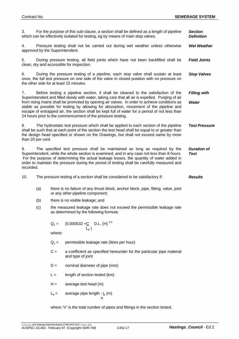
10. The pressure testing of a section shall be considered to be satisfactory if:
(a) there is no failure of any thrust block, anchor block, pipe, fitting, valve, joint or any other pipeline component;
(b) there is no visible leakage; and
(c) the measured leakage rate does not exceed the permissible leakage rate as determined by the following formula:
Q1 = (0.000532 +C D.L. (H) 0.5
Lp ) where: Q1 = permissible leakage rate (litres per hour) C = a coefficient as specified hereunder for the particular pipe material
and type of joint D = nominal diameter of pipe (mm) L = length of section tested (km) H = average test head (m) Lp = average pipe length - L (m) n where “n” is the total number of pipes and fittings in the section tested.
Results
SEWERAGE SYSTEM Contract No.
C:\Documents and Settings\Adam\Desktop\LATM\C402.DOC (2 March, 1999)
C402-18 AUSPEC-1\C402 - February 97 (Copyright SWR-TM)
Hastings_Council - Ed 2
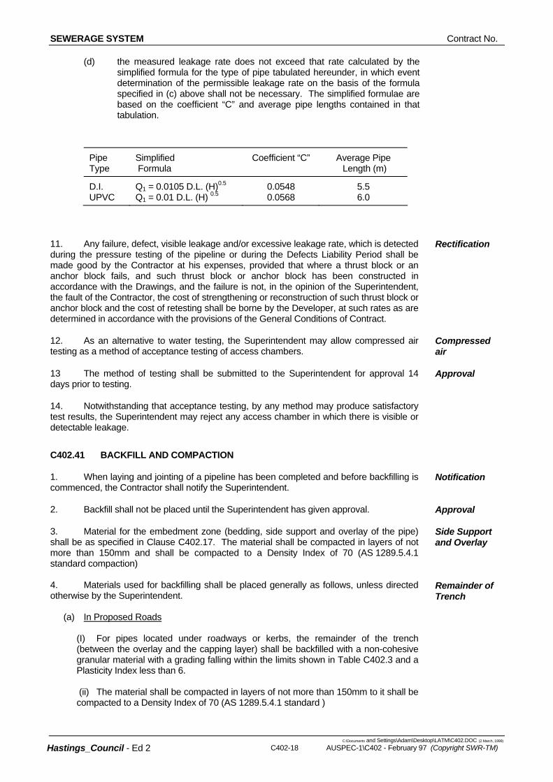
(d) the measured leakage rate does not exceed that rate calculated by the simplified formula for the type of pipe tabulated hereunder, in which event determination of the permissible leakage rate on the basis of the formula specified in (c) above shall not be necessary. The simplified formulae are based on the coefficient “C” and average pipe lengths contained in that tabulation.
Pipe Type
Simplified Formula
Coefficient “C” Average Pipe Length (m)
D.I. UPVC
Q1 = 0.0105 D.L. (H)0.5
Q1 = 0.01 D.L. (H) 0.50.0548 0.0568
5.5 6.0
11. Any failure, defect, visible leakage and/or excessive leakage rate, which is detected during the pressure testing of the pipeline or during the Defects Liability Period shall be made good by the Contractor at his expenses, provided that where a thrust block or an anchor block fails, and such thrust block or anchor block has been constructed in accordance with the Drawings, and the failure is not, in the opinion of the Superintendent, the fault of the Contractor, the cost of strengthening or reconstruction of such thrust block or anchor block and the cost of retesting shall be borne by the Developer, at such rates as are determined in accordance with the provisions of the General Conditions of Contract.
Rectification
12. As an alternative to water testing, the Superintendent may allow compressed air testing as a method of acceptance testing of access chambers.
Compressed air
13 The method of testing shall be submitted to the Superintendent for approval 14 days prior to testing.
Approval
14. Notwithstanding that acceptance testing, by any method may produce satisfactory test results, the Superintendent may reject any access chamber in which there is visible or detectable leakage.
C402.41 BACKFILL AND COMPACTION
1. When laying and jointing of a pipeline has been completed and before backfilling is commenced, the Contractor shall notify the Superintendent.
Notification
2. Backfill shall not be placed until the Superintendent has given approval. Approval
3. Material for the embedment zone (bedding, side support and overlay of the pipe) shall be as specified in Clause C402.17. The material shall be compacted in layers of not more than 150mm and shall be compacted to a Density Index of 70 (AS 1289.5.4.1 standard compaction)
Side Support and Overlay
4. Materials used for backfilling shall be placed generally as follows, unless directed otherwise by the Superintendent. (a) In Proposed Roads
(I) For pipes located under roadways or kerbs, the remainder of the trench (between the overlay and the capping layer) shall be backfilled with a non-cohesive granular material with a grading falling within the limits shown in Table C402.3 and a Plasticity Index less than 6. (ii) The material shall be compacted in layers of not more than 150mm to it shall be compacted to a Density Index of 70 (AS 1289.5.4.1 standard )
Remainder of Trench
Contract No. SEWERAGE SYSTEM
C:\Documents and Settings\Adam\Desktop\LATM\C402.DOC (2 March, 1999) AUSPEC-1\C402 - February 97 (Copyright SWR-TM) C402-19 Hastings_Council - Ed 2
(iii) The final 200mm (minimum) of fill below the underside of Subbase shall be backfilled with material satifying the requirements of Subbase material as per Specification C242 - Flexible Pavements, and shall have a minimum relative compaction of 95 per cent (AS 1289.5.4.1 standard compaction
(b) Elsewhere
Unless stated otherwise, the remainder of the trench shall be backfilled with ordinary excavated fill material. Where suitable material is not available, the Superintendent may direct the use of an approved granular material for the full depth of backfilling. The material shall be compacted in layers of not more than 150mm and shall be compacted to a Density Index of 70 (AS 1289.5.4.1 standard compaction) for cohesionless materials or.95 per cent of the standard maximum dry density of the material used when determined in accordance with AS1289.5.7.1. for cohesive materials
5. Backfilling and compaction shall be carried out without damaging the pipe or its external coating or wrapping or producing any movement of the pipe.
Care
C402.42 RESTORATION OF SURFACES
1. Pavements, lawns and other improved areas shall be cleaned and left in the same order as they were at the commencement of the works. Lawns shall be restored with turf cut and set aside from the original surface and with turf imported from a source approved by the Superintendent.
Original Condition
2. All restored surfaces shall be maintained in the condition to which they are restored until the expiry of the Defects Liability Period applicable to those surfaces, notwithstanding that any deterioration of the restored surfaces, and the need for their maintenance may or may not be due to defects which become apparent or arise from events which occur during the Defects Liability Period. Pavements shall be maintained with crushed metal, gravel or other suitable material allowing for consolidation and shall then be restored to a condition equivalent to that of the original pavement.
Maintenance
3. Immediately the backfilling of a trench excavated through a pavement has been completed, the pavement shall be temporarily restored. Where the trench crosses bitumen or concrete pavement, a pre-mixed asphaltic material shall be used for such temporary restoration. Temporary restoration shall be maintained by the Contractor until final restoration is carried out. Final restoration of the pavement shall be carried out to restore the pavement and its sub-base to no less than the original condition. Final restoration may include, if required by the Superintendent, the removal of temporary restoration.
Temporary Pavement Restoration
4. Backfill shall be placed sufficiently high to compensate for expected settlement and further backfilling shall be carried out or the original backfill trimmed at the end of the Defects Liability Period in order that the surface of the completed trench may then conform with the adjacent surface. Surplus material shall be removed and disposed of to areas arranged by the Contractor.
Backfill
5. In locations where, in the opinion of the Superintendent, surplus material left in the vicinity of the trench would not be objectionable, the surplus material may be disposed by spreading neatly in the vicinity of the trench to the satisfaction of the Superintendent in such a way as to minimise future erosion of the backfill and adjacent ground surfaces. The Contractor shall maintain the backfill and adjacent ground until the expiry of the Defects Liability Period.
Disposal of Surplus Material
6. Where, within public or private property, the reasonable convenience of persons will require such, the Superintendent may order trenches to be levelled off at the time of backfilling. Any subsequent settlement shall be made good by the Contractor, as required by placing additional fill.
Settlement
SEWERAGE SYSTEM Contract No.
C:\Documents and Settings\Adam\Desktop\LATM\C402.DOC (2 March, 1999)
C402-20 AUSPEC-1\C402 - February 97 (Copyright SWR-TM)
Hastings_Council - Ed 2
7. Should the Contractor elect to tunnel under paving, kerb and gutter or other improved surfaces in lieu of trenching, backfilling shall be so carried out as to restore full support to those surfaces, and payment shall be made for the restoration of the surfaces as though they had been removed and replaced. The Contractor shall remain responsible for the repair of the improved surfaces, if subsequently damaged due to subsidence of the backfill, until the end of the Defects Liability Period.
Tunnelling
Contract No. SEWERAGE SYSTEM
C:\Documents and Settings\Adam\Desktop\LATM\C402.DOC (2 March, 1999) AUSPEC-1\C402 - February 97 (Copyright SWR-TM) C402-21 Hastings_Council - Ed 2
PUMPING STATIONS
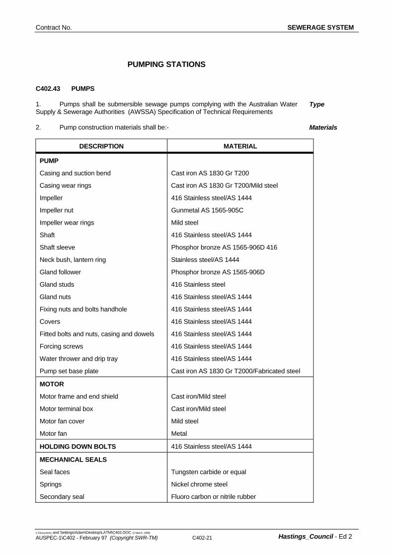
C402.43 PUMPS
1. Pumps shall be submersible sewage pumps complying with the Australian Water Supply & Sewerage Authorities (AWSSA) Specification of Technical Requirements
Type
2. Pump construction materials shall be:- Materials
DESCRIPTION MATERIAL
PUMP
Casing and suction bend Cast iron AS 1830 Gr T200
Casing wear rings Cast iron AS 1830 Gr T200/Mild steel
Impeller 416 Stainless steel/AS 1444
Impeller nut Gunmetal AS 1565-905C
Impeller wear rings Mild steel
Shaft 416 Stainless steel/AS 1444
Shaft sleeve Phosphor bronze AS 1565-906D 416
Neck bush, lantern ring Stainless steel/AS 1444
Gland follower Phosphor bronze AS 1565-906D
Gland studs 416 Stainless steel
Gland nuts 416 Stainless steel/AS 1444
Fixing nuts and bolts handhole 416 Stainless steel/AS 1444
Covers 416 Stainless steel/AS 1444
Fitted bolts and nuts, casing and dowels 416 Stainless steel/AS 1444
Forcing screws 416 Stainless steel/AS 1444
Water thrower and drip tray 416 Stainless steel/AS 1444
Pump set base plate Cast iron AS 1830 Gr T2000/Fabricated steel
MOTOR
Motor frame and end shield Cast iron/Mild steel
Motor terminal box Cast iron/Mild steel
Motor fan cover Mild steel
Motor fan Metal
HOLDING DOWN BOLTS 416 Stainless steel/AS 1444
MECHANICAL SEALS
Seal faces Tungsten carbide or equal
Springs Nickel chrome steel
Secondary seal Fluoro carbon or nitrile rubber
SEWERAGE SYSTEM Contract No.
C:\Documents and Settings\Adam\Desktop\LATM\C402.DOC (2 March, 1999)
C402-22 AUSPEC-1\C402 - February 97 (Copyright SWR-TM)
Hastings_Council - Ed 2
C402.44 ELECTRICAL COMPLIANCE
1. The works shall be in accordance with the Department of Public Works General Requirements for Building Services (Electrical Installations) dated June, 1984, including amendment 1 August 1987 (known as EDS E101) and General Requirements for Water Supply - Section B except where ‘Hastings Council - Minor Sewerage Pumping Station Requirements (1992)’, this Specification or the Drawings indicate otherwise.
Standards
2. ‘Hastings Council - Minor Sewerage Pumping Station Requirements (1992)’ shall take precedence over the requirements of this specification should clauses be in disagree ment
Precedence
3. PWD-EDS E101 covers the Department’s general requirements for materials, workmanship, and methods of installation as follows: Part 0 Generally Part 1 Reticulation and Wiring Part 2 Switchboards and Equipment Part 3 Accessories Part 4 Luminaries - Supply and Installation Part 5 Electric Motors Part 6 Painting, Colour Coding and Labelling
EDS 101
4. Except where PWD-EDS E101 and PWD-B requires a higher standard, works shall be carried out in accordance with AS 3000, the Service Rules of the Supply Authority and all relevant Statutory Authorities.
Compliance
5. Proof of compliance with a standard or specified test may be required. Where requested, such proof shall comprise a test certificate from an approved independent testing authority.
Proof of Compliance
6. The Contractor shall submit all designs and material to each Authority having jurisdiction for approval, as required. The Contractor shall arrange for each Authority having jurisdiction to inspect the works. The Superintendent shall be advised a minimum of 7 working days in advance of the date of any inspection by an Authority.
Approval
C402.45 SWITCHGEAR AND CONTROL GEAR ASSEMBLY (SCA)
1. The switchboard shall be designed and assembled by a manufacturer approved by the Superintendent.
Manufacturer
2. The SCA shall be of outdoor, stationary, free standing, metal-enclosed, cubicle type series with a minimum degree of protection of IP56D as specified in AS 1939.
Type
3. All equipment shall be securely mounted on suitable mounting panels and comprise individual compartments. A steel galvanised channel base shall be provided.
Construction
4. Starter contactors shall have the appropriate rating for the proposed pumps to AC3.
Starter Contactors
5. All necessary terminals with terminal and cable numbers shall be supplied and installed in accordance with the Drawings.
Terminals
6. The Superintendent will supply Council Standard locks for use on the SCA. Lock Barrels
7. The electrical characteristics of the SCA shall be:- Main Circuit: 415/240 V, 50 Hz, 3-phase, 4-wire. Motor Control Circuit: 240 V, 50 Hz.
Characteristics
Contract No. SEWERAGE SYSTEM
C:\Documents and Settings\Adam\Desktop\LATM\C402.DOC (2 March, 1999) AUSPEC-1\C402 - February 97 (Copyright SWR-TM) C402-23 Hastings_Council - Ed 2
Common Control Circuit: 240 & 24 V, A.C. Prospective short-circuit current: 14kA for 1 second. Peak Factor: 2.2 Power Factor Correction ( As determined in consultation with Hastings Council) Earthing (M.E.N. system)
8. All cables shall enter the SCA from below. Cable Entry
9. Data from the switchgear supplier confirming Type “2” co-ordination between contactors, motor protection relays and corresponding circuit breakers shall be submitted to the Superintendent.
Switchgear
Data
10. Install telemetry equipment for automatic control signals. Telemetry
11. The “AUTO” mode shall be capable of being overridden by turning the starter selector switch to the “ON” position. Manual operation would normally be used in the event of failure of the telemetry system or for function testing. A warning label (R/W/R) advising selector switches to be left in the “AUTO” mode shall be fitted to common control cover.
Operation
12. Factory tests shall be carried out in the presence of the Superintendent’s Representative and in accordance with Schedule EDS-E101 and shall comprise all routine Tests specified in AS 3439. The Superintendent shall be given seven (7) days notice of the proposed date of such tests.
Factory Tests
13. Functional tests referred to in Schedule EDS-E101 shall include electrical function tests as defined in AS 3439.
Functional
Tests
14. After satisfactory final factory inspection and tests and after approval has been given by the Superintendent, the equipment shall be packed for transport. Any relays and fittings likely to be adversely affected during delivery shall be adequately protected or shall be removed and packed separately in protected containers. Where equipment has been removed, cover plates shall be provided.
Packing
15. The Contractor shall be responsible for any damage that may occur during transit and unloading at site.
Damage
16. Spare parts, tools etc, shall be packed separately from the main plant and shall be marked “Spare Parts”, “Tools” etc, as applicable.
Tools
17. Supply three spare globes for every ten indicating lamps (together with removal tool); one (1) spare coil and one (1) three phase set of contacts (or complete contactor) within the SCA together with two (2) off each of the following 240V and a.c. relay; 240V a.c. timer; 24V a.c. relay; 24V a.c. timer and thermistor relay.
Spare Parts
C402.46 ELECTRICAL INSTALLATION
1. The Contractor shall liaise with the Supply Authority for the electricity supply to the pumping station site.
Liaison
2. All facilities required by the Supply Authority for revenue metering equipment and the payment of all associated connection, inspection fees and capacity charges shall be the responsibility of the Contractor.
Contractor’s Responsibility
3. All cabling including consumer mains, motor, control and flow meter cables, conduits and electrical pits shall be supplied and installed by the Contractor.
Cabling
4. All wiring shall be installed in HD-UPVC underground conduits laid a minimum Conduits
SEWERAGE SYSTEM Contract No.
C:\Documents and Settings\Adam\Desktop\LATM\C402.DOC (2 March, 1999)
C402-24 AUSPEC-1\C402 - February 97 (Copyright SWR-TM)
Hastings_Council - Ed 2
(a) All electricity meters (traiffs) supplied by the Electricity Supply Authority.
500mm below the finished ground level in non-trafficable areas and 600mm below the finished ground level in trafficable areas. The trench and backfill material shall be free of rocks and other foreign matter likely to damage the conduits.
5. Electrical marker tape shall be run 150mm below the finished ground level directly above the conduits for the entire length of the conduits. Marker tape shall be orange in colour, 150mm wide and stamped with the words “DANGER - ELECTRIC CABLES BELOW” or similar.
Marker Tape
6. The route of all underground cabling shall be approved by the Superintendent and the Supply Authority prior to commencement of trenching. Brass marking plates shall be positioned on the concrete surround clearly showing the direction of the incoming consumers mains. Wording and markings shall be similar to “Danger Electrical Cables Below” with directional arrows engraved.
Route
7. The Points of Attachment shall be determined on site by the Contractor and any consumer’s connection poles for the consumer mains required by the Supply Authority shall be supplied and installed by the Contractor.
Point of Attachment
8. The consumer mains shall be generally run underground and commence at the Point of Attachment on a steel consumers pole (if applicable), installed near the property boundary and run in conduit to the switchboard.
Consumer Mains
9. The minimum size of the consumers mains shall be sized to satisfy the following requirements:
(a) Current carrying capacity to suit the maximum demand with an excess current carrying capacity of 30% minimum.
(b) Be sized for a voltage drop less than 1.5% to the maximum demand as calculated.
(c) Be single core PVC/PVC cables. XLPE insulated cable may also be used.
(d) Comply with the requirements of the Supply Authority.
(e) Pole termination method shall be as shown on the Drawings.
(f) AS3000 and AS3008
Size
10. In addition to the requirements of the Supply Authority and EDS E101 the main earthing conductor shall be run in conduit to the main earthing electrode. The main earthing connection shall be contained in an earthing electrode connection box similar to ALM type ERB-1 up to 50mm2 cable and a Type 4 pit for larger cable.
Earthing Conductor
11. A separate earthing conductor and electrode shall be provided for the surge diverters. Each electrode shall be bonded and suitably labelled with an engraved brass label.
Surge Diverters
12. If shown on the drawings or directed by the Superintendent,the pumping station pipework shall be bonded to the main earth.
Pipework
13. Metering facilities shall be installed within the SCA. The metering facilities and panel shall be Energy Authority approved and suitable for the installation of the metering equipment required by the Supply Authority.
Meters
14. The following metering equipment shall be supplied and installed:-
(b) Service potential fuses.
(c) Current transformers metering equipment (if required).
Metering Equipment
Contract No. SEWERAGE SYSTEM
C:\Documents and Settings\Adam\Desktop\LATM\C402.DOC (2 March, 1999) AUSPEC-1\C402 - February 97 (Copyright SWR-TM) C402-25 Hastings_Council - Ed 2
(d) All necessary wiring and other accessories as required by the Supply Authority. (H.C. contestable site)
(e) Key locking facilities for Supply Authority access.
15. Cables entering the outdoor SCA compartment shall be glanded using non-ferrous metallic or plastic glands with neoprene compression seals. Connect the on-flow switch and pump motor cables to the appropriate terminals. Cables shall not be jointed.
Cable Entry
16. At the completion of commissioning tests all conduits into the outdoor SCA shall be sealed with a non setting sealing compound to prevent the ingress of vermin.
Sealing
C402.47 TESTING AND COMMISSIONING OF PUMPING STATION
1. All materials, equipment, installation and workmanship shall be tested and/or inspected to prove compliance with the Specification requirements.
Compliance
2. Tests and inspections shall comply with relevant Australian Standards. Standards
3. Testing shall include pre-commissioning, field testing and performance testing of each part of the whole installation.
Testing
4. Pre-commissioning is the preparation of plant or equipment so that it is in a safe and proper condition and ready for commissioning and operation. It includes all aspects of plant operation such as safety, electrical, mechanical and instrumentation.
Pre-
Commissioning
5. Pre-commissioning shall be conducted in a logical sequence in accordance with the programme prepared by the Contractor and approved by the Superintendent.
Sequence
6. The Contractor shall prepare pre-commissioning record sheets for each item of equipment to ensure results of tests are satisfactorily recorded and that all necessary checks or tests have been performed.
Record Sheets
7. Specific requirements for pre-commissioning/commissioning shall include, but are not limited to:-
(a) Initial charges of lubricant in addition to any special lubricant requirements for initial flushing or treatment of the system or for “running in”.
(b) Physical checks and tests such as completeness of assembly, rotational tests (including checking that the rotation of electrical motors is in the correct direction), alignment checks, balancing and vibration checks, temperature, pressure and flow measurements, clearances, belt alignment and tension, etc, depending on the type of equipment.
(c) Electrical and instrument installation tests, including motor insulation tests and checking instruments against certified instruments and correcting as necessary.
(d) Tests of the correct functioning of automatic and manual control and protection equipment, including simulating danger conditions, mal-operations or failures, to check that all instruments and controls function correctly. These tests shall also include adjusting instrument set points and alarm settings and proving correct operation of alarms.
(e) Equipment and system operating tests. The Contractor shall certify compliance of each item and submit a signed copy to the Superintendent prior to commissioning.
Requirements
8. Pre-commissioning tests shall be carried out to the satisfaction of the Superintendent and shall be recorded on the appropriate Pre-commissioning Record Sheet.
Recording
9. The Contractor shall furnish the Superintendent with one signed copy of each Submission
SEWERAGE SYSTEM Contract No.
C:\Documents and Settings\Adam\Desktop\LATM\C402.DOC (2 March, 1999)
C402-26 AUSPEC-1\C402 - February 97 (Copyright SWR-TM)
Hastings_Council - Ed 2
C402.50 OPERATION AND MAINTENANCE MANUALS
completed Pre-commissioning Record Sheet countersigned by the Superintendent’s Representative who witnessed the test.
10. Commissioning is the running of the plant and equipment to ensure flow through the pumping system, carrying out any necessary testing and adjustments until it is ready and suitable for normal starting and running under service conditions.
Commissioning
11. The Superintendent shall be given five (5) working days notice of the Contractor’s intention to undertake commissioning.
Notification
12. Commissioning shall be conducted in a logical sequence in accordance with a programme prepared by the Contractor and approved by the Superintendent.
Sequence
13. Throughout commissioning the Contractor shall be responsible for the test programme.
Responsibility
14. The Contractor shall provide continuous supervision by personnel experienced in the operation of the equipment and shall have qualified personnel in attendance to carry out all necessary adjustments and/or remedial work during the commissioning tests.
Supervision
15. The Contractor shall prepare, schedules, test record sheets and programmes for approval by the Superintendent prior to each stage of the overall commissioning.
Documentation
16. Final testing and commissioning (min 1 day duration) of the electrical services in conjunction with the mechanical equipment (e.g. pump, etc) including setting and adjustment of equipment shall be carried out in accordance with EDS E101.
Final Testing
17. The Contractor shall arrange for all testing, commissioning and any adjustments to be carried out by qualified personnel.
Qualified Personnel
C402.48 PRACTICAL COMPLETION OF PUMPING STATION
1. The following requirements shall be fulfilled before the Certificate of Practical Completion is issued:-
- Certificate of approval from the relevant statutory authorities have been received by the Superintendent.
- Pumping station is in working order as demonstrated by the testing and commissioning.
- Operating and maintenance manuals have been approved by the Superintendent.
- As-built drawings of the pumping station have been submitted to the Superintendent.
C402.49 TELEMETRY
1. Equipment to link the pumping station to the existing telemetry network will be provided by Council at the Contractor’s expense.
Contractor’s Cost
2. The pumping station shall operate automatically by control signals from the telemetry system. In addition, either one or any combination of pumps may operate at any one time by control signals from the telemetry system.
Operation
1. Manuals shall contain the following information:
Contract No. SEWERAGE SYSTEM
C:\Documents and Settings\Adam\Desktop\LATM\C402.DOC (2 March, 1999) AUSPEC-1\C402 - February 97 (Copyright SWR-TM) C402-27 Hastings_Council - Ed 2
(a) Contractor’s name, address and telephone number.
6. The operating and maintenance manual shall include:-
- Safe working procedures: For switching and isolating the supply and distribution system;
Operation and Maintenance
SEWERAGE SYSTEM Contract No.
C:\Documents and Settings\Adam\Desktop\LATM\C402.DOC (2 March, 1999)
C402-28 AUSPEC-1\C402 - February 97 (Copyright SWR-TM)
Hastings_Council - Ed 2
- Description of Operation;
- Maintenance procedures: Recommended maintenance periods and procedures;
- Tools: Particulars of maintenance equipment and tools provided, with instructions for their use.
- Equipment: A technical description of the equipment supplied, with diagrams and illustrations where appropriate;
- Dismantling: Where necessary, procedures for dismantling and reassembling equipment;
- Spare parts: A list of the spare parts provided.
7. Trouble shooting instructions shall be included for pumps, motors, valves and SCA. Trouble Shooting
8. Step by step procedures for dismantling and reassembly of pumps, motors and valves using any special tools shall be detailed together with step by step procedures for replacement of wearing parts such as bearing, seals, wear rings, etc.
Replacement Procedures
SPECIAL REQUIREMENTS
C401.51 YEAR 2000 COMPLIANCE WARRANTY Year 2000 Warranty
1. The Contractor warrants that products or systems provided under this Contract shall be Year 2000 Compliant when used in the environment and conditions specified in the Schedule - YEAR 2000 COMPLIANCE - and any documents supplied by the Customer.
2. In this Contract “Year 2000 Compliant” means a product or system that accurately processes date and date related data including, but not limited to, calculating, comparing, and sequencing from, into, and between the twentieth and twentyfirst centuries and the years 1999 and 2000 and all leap year calculations.
3. Notwithstanding that this Contract or any warranty provision in it is expressed to endure for a period of time, the warranty provided for in subclause 1 shall survive termination of this Contract and shall endure for the life of the product or system.
4. On demand being made by the Customer or upon the Contractor first becoming aware (whichever is the first) of anything in the product or system which causes or may cause a breach in the warranty in sub clause 1, the Contractor shall immediately remedy or correct the breach or apprehended breach whether or not the breach or apprehended breach of warranty has resulted in a failure by the product or system at the time of the Customer’s demand or the Contractor’s awareness.
5. The Contractor shall indemnify, keep indemnified and hold the Customer harmless against all losses, costs, demands and expenses whatsoever arising which the Customer may sustain as a result of a breach of the warranty in subclause 1.
Contract No. SEWERAGE SYSTEM
C:\Documents and Settings\Adam\Desktop\LATM\C402.DOC (2 March, 1999) AUSPEC-1\C402 - February 97 (Copyright SWR-TM) C402-29 Hastings_Council - Ed 2
C401.52 YEAR 2000 COMPLIANCE SCHEDULE Year 2000 Schedule
1. This Schedule records the environment and conditions in which the products or systems are warranted to be Year 2000 Compliant. There will be deemed to be an express warrant of Year 2000 Compliance by the Contractor that what the Contractor supplies will meet requirements of the documents supplied by the Customer unless the Contractor has expressly informed the Customer in the tender that what the Contractor offers will not meet some or any of these requirements.
2. APPLICABILITY If it is considered that any of the products or systems offered are not potentially susceptible to Year 2000 Compliance problems, list here such products or systems and state the reasons.
3. THE DOMAIN State here a definition of the domain in which the products or systems offered, other than those listed in Item 1. are warranted to be Year 2000 Compliant. This should specifically include the operating conditions and any interfaces to other equipment. The domain may be described by either documenting all the included operating conditions where these products or systems are warranted to be Year 2000 Compliant or by documenting all the operating conditions where these products or systems are not warranted to be Year 2000 Compliant.
4. THE METHOD OF ACHIEVING COMPLIANCE Supply here a full definition of how the products or systems, other than those listed in Item 1. achieve Year 2000 Compliance including all options for the management of date values. Details of any date parameters used by the method must be stated. For example if a “windowing technique” or other algorithm is used to interpret dates, the logic of the algorithm should be stated and the parameters used in the calculation of date values.
5. THE EXCHANGE OF DATE VALUES WITH OTHER PRODUCTS If the products or systems, other than those listed in Item 1. include any facility for exchanging dates with other products or systems, list here full details of the date format options. These should include date formats that these products or systems may import from other products and systems and export to other products and systems where applicable.
6. TESTING OF COMPLIANCE Provide here details of all tests that have been performed on the products or systems, other than those listed in Item 1. to determine their Year 2000 Compliant status and that are relied upon in claiming such compliance. This should include details of third party testing facilities or users where applicable. If any third party statements are being relied upon to claim Year 2000 Compliance they must be listed here. For example, if a software application vendor is claiming compliance because an operating system vendor or a database vendor has claimed compliance this must be stated.
C402.53 Reserved
C402.54 Reserved
SEWERAGE SYSTEM Contract No.
C:\Documents and Settings\Adam\Desktop\LATM\C402.DOC (2 March, 1999)
C402-30 AUSPEC-1\C402 - February 97 (Copyright SWR-TM)
Hastings_Council - Ed 2
MEASUREMENT AND PAYMENT
C402.55 PAY ITEMS
1. Payment shall be made for all the activities associated with completing the work detailed in this Specification in accordance with Pay Items C402(a) to C402(k) inclusive.
2. If any item for which a quantity of work is listed in the Schedule of Rates has not been priced by the Contractor, it shall be understood that due allowance has been made in the prices of other items for the cost of the activity which has not been priced.
3. Concrete for bedding, junctions for risers, bulkheads, thrust and anchor blocks, concrete encasement, cast-in-situ access chambers and pumping stations is measured and paid in accordance with this Specification and not in the Specification for MINOR CONCRETE WORKS.
4. Miscellaneous minor concrete work not included in the pay items in this specification shall be in accordance with pay items described in the specification for MINOR CONCRETE WORKS.
Pay Item C402(a) EXCAVATION FOR SEWERS
1. The unit of measurement shall be cubic metre measured as bank volume of excavation.
2. The schedule rate for this Pay Item shall be an average rate to cover all types of material encountered during excavation. Separate rates shall not be included for earth and rock.
3. The rate is deemed to include:
• Setting out and associated survey
• Excavation, including excavation and replacement of unsuitable material.
• Backfilling, other than selected backfill, of sewers
• Restoration of surface
• Replacement for over-excavation for any reason
• Control of stormwater runoff, temporary drainage and erosion and sedimentation control.
4. The volumes of excavation for payment shall be computed as follows:
Trench Width: Minimum width in Table 402.1 + 200mm.
Trench Depth: Average actual depth to underside of specified bedding.
Trench Length: Actual excavation length, centre to centre of manholes or centre of manhole to face of structure.
Pay Item C402(b) SEWER PIPE
1. The unit of measurement shall be the linear metre measured along the centreline of each particular type of sewer pipe and shall be the plan length between centres of access chamber or centre of access chamber to face of structure.
2. The schedule rate shall include:
• Supply of pipe and fittings
• Wrapping pipeline
• Survey and setting out
Contract No. SEWERAGE SYSTEM
C:\Documents and Settings\Adam\Desktop\LATM\C402.DOC (2 March, 1999) AUSPEC-1\C402 - February 97 (Copyright SWR-TM) C402-31 Hastings_Council - Ed 2
• Bedding (including concrete bedding)
• Junctions and sidelines
• Bulkheads
• Thrust and anchor blocks
• Jointing (including connections)
• Temporary bracing and strutting of excavation
• Selected backfilling
• Quality testing
Pay Item C402(c) ACCESS CHAMBERS
1. The unit of measurement shall be per “each” installed.
2. The schedule of rate for precast concrete access chamber shall include for the supply, setting out, excavation, installation including step irons and benching, backfilling and disposal of spoil off site. It shall also include for temporary stockpiling prior to backfilling, control of stormwater run off and erosion and sedimentation control.
3. The schedule rate for cast in situ access chamber shall include for the setting out, excavation, formwork, supply and placing concrete, supply and fixing step irons, placing benching, backfilling, disposal of spoil off site and making live connections where necessary. It shall also include for temporary stockpiling prior to backfilling, control of stormwater run off and erosion and sedimentation control.
4. As separate unit rate shall be included in the Schedule of Rates for each type and size of access chamber.
Pay Item C402(d) COVERS AND SURROUNDS
1. The unit of measurement shall be per “each” installed.
2. The schedule rate for covers and surrounds shall include for the supply, installation and grouting.
3. A separate unit rate shall be included in the Schedule of Rates for each size and type of surround and cover.
Pay Item C402(e) CONNECTION TO EXISTING
1. The unit of measurement shall be per “each” connection to existing access chamber or structure.
2. The schedule rate for connection to existing shall include for all the necessary works to blank off, sand fill, cut into or otherwise modify and finish the system as shown on the Drawings.
Pay Item C402(f) TRENCH TIMBERING LEFT IN PLACE
1. The unit of measurement shall be the cubic metre of timber directed to be left in place by the Superintendent.
2. No extra payment shall be made where the timber used exceeds the size of timber required as determined by the Superintendent.
3. The schedule rate shall include the supply of timber only.
SEWERAGE SYSTEM Contract No.
C:\Documents and Settings\Adam\Desktop\LATM\C402.DOC (2 March, 1999)
C402-32 AUSPEC-1\C402 - February 97 (Copyright SWR-TM)
Hastings_Council - Ed 2
Pay Item C402(g) CONCRETE ENCASEMENT
1. The unit of measurement shall be the linear metre measured along the centreline of each particular type of concrete encasement.
2. The schedule rate shall include for additional excavation, formwork, reinforcement, concrete and contraction joints.
Pay Item C402(h) PUMPING STATION
1. The item shall be a Lump Sum for each Pumping Station.
2. The Lump Sum shall include for the setting out, excavation, preparation of foundation, formwork, reinforcement, concreting, curing concrete, backfilling, disposal of spoil off site, supply and installation of pipework, valves, fittings, access cover, ladder and cleaning up. It shall also include for temporary stockpiling prior to backfilling, control of stormwater run off and erosion and sedimentation control.
Pay Item C402(i) SEWER PUMPS
1. The item shall be a Lump Sum for each Sewer Pump.
2. The Lump Sum shall include for the supply and installation of the system as specified and as detailed on the Drawings including suction and discharge pipework, valves, fittings, control panel and cabinet, power and control wiring and testing.
Pay Item C402(j) COMMISSIONING
1. The item shall be a Lump Sum.
2. The Lump Sum for Commissioning shall include for all labour, test equipment and consumables to undertake and record the full commissioning procedure for all equipment and systems, and to carry out all necessary modifications and adjustments to the system so that it operates in accordance with the Specification requirements.
Pay Item C402(k) MANUALS
1. The item shall be a Lump Sum.
2. The Lump Sum for Manuals shall include for the preparation and printing of the operating and maintenance manuals in accordance with the Specification. Necessary and appropriate “as-built” drawings shall be included.
Contract No. SEWERAGE SYSTEM
C:\Documents and Settings\Adam\Desktop\LATM\C402.DOC (2 March, 1999) AUSPEC-1\C402 - February 97 (Copyright SWR-TM) Hastings_Council - Ed 2
)
SPECIFICATION C402 - SEWERAGE SYSTEM CLAUSE CONTENTS PAGE
C402.10 COVER OVER PIPELINES......................................................................................................................... 3
PIPELINE TESTING AND RESTORATION ............................................................................13
C402.32 GENERAL .................................................................................................................................................. 13