ABSTRACT Oil and gas refineries present challenging environments in
which to work and operate, especially in places like the Middle East where temperatures can reach 50 ○C and sand storms which can reduce visibility to a few meters. In addition, there can be gas or steam leaks which present health and safety hazards to the workers. At present, continuous operation of these plants requires that human workers venture out into these conditions in order to observe and report on the conditions within the plant. The goal of this work is to design, fabricate, assemble, and test an inspection robot in an effort to reduce the exposure and risks to human operators while increasing the flexibility and range of remote observations provided by a mobile robot.
In this paper, we will report on the design approach taken, the subsystems identified and developed, the software environment chosen, and the application tasks envisioned. We will also report on the challenges of developing a robust localization algorithm for use in the challenging environment of a refinery as well as the needs for robust wireless communications in order to maintain command and control
from the operators control room. An overview of the five-degree-of-freedom arm designed and fabricated, and its real-time control will also be presented. Results from GPS navigation and localization experiments will be presented. While average errors during parked operations were often less than one meter for the WAAS enabled GPS system, locational errors during dynamic operations were often more than three meters. This is due to multi-path signals near building structures and piping infrastructure. Real-time arm control has been implemented using FPGAs and while tuning presented some challenge, the FPGA has provided smooth and repeatable operation. Sensors include gas detectors, acoustic sensors, thermal imaging, and video camera streaming. In addition, we will report on a multi-faceted approach to localization using three different sensor technologies and integrated using a Kalman filter.
NOMENCLATURE DOF Degrees-of-Freedom GPS Global Positioning System FPGA Field Programmable Gate Array PWM Pulse Width Modulation
PID Proportional-integral-derivative RMP Robotic Mobility Platform WAAS Wide Area Augmentation System AP Access Point
INTRODUCTION The motivation for this project comes from the desire for
greater safety and reduced exposure for workers in petroleum refining and processing facilities. Exposure to hazards as well as the elements puts human operators at risk. The goal of this project has been to design, fabricate, and test a robot that will be capable of performing many of the routine tasks that are currently carried by human workers so that the worker can assume a supervisory role and focus more on problem solving.
Demands of a Petrochemical Refining Environment.
Intended Use Oil refineries and petrochemical plants are typically harsh
environments by nature. The oil and gas industry in Abu Dhabi, the United Arab Emirates, is among the biggest in the world. The hot and humid weather, where it reaches 50 degrees C in the summer, adds considerably to the harshness of the work environment.
Due to the sensitivity of the operations within a refinery (i.e. the risks involved, and the potential of losing millions of dollars as a result of even one day of lost production), a great deal of routine inspection is required on a daily basis. In addition to this routine inspection of equipment, pipelines, gauges, etc; emergency inspections are often required when alarms are raised. In such case, there is a potential risk on the persons carrying out the inspection. Accidents occurred in the past where lives were lost due to unsuspected gas leaks in the area that was being inspected.
The harshness and the intrinsic risks at these refineries and plants motivated the oil and gas industry to actively look for a safer and more reliable alternative to the current methods of inspection. One approach that is being trialled is using wireless transmitters and cameras. However, this approach requires a large number of wireless transmitters and cameras to be deployed, and even in this case, some critical gauges require onsite reading by an operator for verification. A mobile robot equipped with cameras and sensors provides a safe and reliable alternative to the physical inspection approach, while at the same time represents a less costly and more effective alternative to the wireless transmitter approach.
Related Work
Robot Sentries. Some of the first proposed applications for mobile robots
was as robot sentries to travel around in buildings and sensor for intruders and detect conditions that would need attention, e.g., a water leak. To a very large extent, these projects were
unsuccessful due to the inability of the robot to reliably carry out its mission.
Offshore Platforms. Work has been going on for a while to develop robot manipulators that could take over some of the routine tasks on an offshore platform [4][5], but these have been primarily paper studies.
Oil & Gas Industry. Designing an unmanned robot to work in oil and gas facilities has attracted attention recently. A prototype system that performs sensor based close-contact operations in explosive atmospheres was designed [1]. The required hardware and software components and abilities of a mobile offshore inspection and manipulation robot are presented in [2]. Despite all the existing work described here, system integration remains a grand challenge. Further, developing a fully functional robotic system in the field poses many more additional challenges than just testing it in a lab. For example, obstacle avoidance takes on a whole new meaning when dealing with a “real-world” environment. Not only are there the expected obstacles and limited passage ways that are part of every path planning exercise [3], but there are also the unexpected obstacles like cracks in the pavement or bumps in the roadway that must be successfully circumnavigated.
DESIGN REQUIREMENTS & FUNCTIONAL SPECIFICATIONS
Environmental Requirements As mentioned previously, the environment can be
challenging; sand storms, high temperatures (greater than 50 ○C) and the need to operate both day and night can be difficult for human workers.
In addition, a worker can be exposed to leakage of hazardous gases such as methane, hydrogen sulfide, sulfur dioxide, or benzene, as well as steam leaks and the potential for explosions from hydrocarbon build up.
Operational Requirements To deploy a mobile robot in this kind of environment
requires overcoming several challenges. It must be developed to operate at temperatures of 50 ○C. It must be equipped with a robotic ARM with excellent degrees of freedom for reliable sensing and inspection capabilities. The sensing capability must at minimum be able to perform visual feedback, sniffing, and listening. The robot must be able to navigate in confined spaces and also on any kind of floor. It must also be able to plan its route, detect and maneuver around known and unknown obstacles especially pipes. It must be able to build and update map of the environment and localize itself within it for autonomous inspections. Excellent and robust communication network for remote operation and monitoring purposes are also essential, as reliable data transmission must be ensured. The robot must be capable of detecting obstacles and preventing collision in case of over-sight by the operator. It must be
designed to be fail-safe in times of loss of network connection. It should be simple to use and program for inspection purposes. In addition, it must be capable of manual over-ride at any point in time[2].
Unlike most already implemented inspection robots in oil and gas facilities (offshore), a refinery covers a large expanse of land. Hence, a strong and stable mobile platform must be used with a long run-time without charging and a short charging period. It must also be able to cover long ranges in short period of time. In summary, the mobile robot must be designed to be durable, robust and rugged to navigate reliably in both indoor and outdoor environments, in order to perform inspection tasks without any problem.
SUBSYSTEMS Our robot, see Figure 1 is made up of several subsystems:
the mobile platform which provides the locomotion, a robot arm which provides the positioning of the sensor head, a variety of sensors which allow the robot to detect, monitor, and interact with its environment, a command, control, and communications system that connects the operator to the robot, provides the monitoring and oversight of the robot including mission control, which allows the operator to define the mission and tasks for which the robot is intended.
Mobile Platform RMP. In order to have time to focus on the design of the
robot arm and the operational software, a decision was made to shop for an off-the-shelf solution for the mobile platform. Few commercially available platforms met our requirements: robust enough to travel across open land, have a maximum speed of at least 5 km/hour, be capable of carrying a payload (the arm) of about 50 kg, and provide a programming interface that would allow us to start programming the robot immediately. From the choices available we selected the Segway RMP 440 LE. It exceeded our requirements and we felt it’s rugged design would prove to be beneficial to the project.
The RMP comes with a three different communication interfaces: Ethernet, UBS, and CAN. We chose to use the USB for its simplicity. At the lowest level, motion commands are rate commands for linear and rotational motion, i.e., forward velocity of 1 m/s or clockwise rotation of 45 degrees / second. It also provides state variables like linear accelerations, linear velocity, linear displacement, angular velocity about X,Y and Z-axis, roll angle, pitch angle, battery status, etc. at a maximum polling rate of 100Hz.
Initial experiments were performed to determine the behavioral characteristics of the RMP in terms of accuracy and precision. Additionally, further tests were performed to determine the extent to which the RMP interfered with other sensing systems primarily, GPS, Wi-Fi and digital compass. Although these effects were small, findings from the experiments were considered in the final system design and
position estimation.
Robot Arm (Head)
Requirements The robot arm was designed with the intention that it would
be capable of providing a viewing experience for the operators that would be as if they themselves were performing the inspection. To meet this requirement, five degrees of freedom was determined to be adequate. In addition to this the maximum height of the robot arm was chosen to be slightly taller than the average human. To make driving easier for the operator, when the robot arm is in the parked position the inspection camera is looking in the forward direction of travel for the RMP.
Design Philosophy
The robotic arm was designed with simplicity, modularity and ease of assembly in mind. Joints 1,2 and 3 all are driven by the same model of DC motor, however each joint’s gear ratio is different, this allows for easy maintenance, serviceability and troubleshooting. To make integration of the motors and motor controller simpler, the DC motors chosen had encoders incorporated into them off-the-shelf. Joints 4 and 5 share the same style of off-the-shelve servo motors with an incorporated gear box. By using two different types of motors only two motor mount designs were required. The robotic arm and robotic arm assembly where manufactured out of aluminum in order to reduce the weight of the arm assembly. A lightweight arm design served two primary purposes: first it allowed the arm to move fast, and second keeping the weight of the arm assembly down so that it could be easily removed from the RMP by operators. To keep the robotic arm's design as simple as possible, worm gearboxes where used for Joints 2 and 3. Worm gearboxes cannot be back driven by a load on the output shaft, this allows the robotic arm to move to a position and remain there without the need for brakes or continuously applied power to the motors. This made the mechanical design of the robotic arm simpler and helps to maximize inspection time by not draining the batteries during times of static pose. To ensure safe operation, the robotic arm was also provided with limit switches to provide hardware stops as well as for finding joints' zeroposition.
Given the short time span of the project it seemed unfeasible to have complete design of the robot completed before manufacturing began. Therefore, a concurrent design and manufacturing approach was taken. Components could be manufactured and integrated before the entire assembly was designed. This allowed for both an expedited project timeline and for easier system level integration.
Sensors The robot is provided with several sensing capabilities for
navigation and environmental information gathering to emulate the senses of a human operator e.g., hearing, smelling and seeing.
Navigation Sensors • GPS Receiver: A Garmin GPS, WAAS enabled
with an update rate of 1Hz was mounted on the robot for determining its location in the world coordinate system. This GPS unit provides location information that includes Longitude, Latitude, Altitude, fix, estimated position error, the number of satellites being used, in a proprietary form which are used in determining the integrity of position data.
• Digital compass: In many robot applications, heading is calculated from the history of the GPS data. However in our application, multi-path signals near building structures and piping infrastructure are often encountered making this kind of technique unfeasible. To determine heading, an OceanServer precision 3-axis tilt
compensated digital compass with a high update rate of 40Hz was mounted on the robot. It provides an heading accuracy of 0.5° RMS heading while level, 1° RMS <±30° Tilt, and 1.5° RMS <±60° Tilt. Also, it can be calibrated for hard and soft iron compensation.
• Scanning Laser Range Finder: The robot is equipped with a 2D Hokuyo URG-04LX-UG01 laser scanner capable of a maximum range of 4m, a detection area of 240 degrees with a scan time of 100msec/scan (10 Hz). This provides the robot with the capability to detect and avoid collision with obstacles. It is also being used to create maps of its environment.
• Infrared Proximity Sensor: Four distance measuring sensor units with a detection range of 20-150cm are attached to the front and rear bumpers, pointing directly ahead of the four tires of the RMP. These sensors are used to ensure that the robot does not drive down a flight of stairs or off a ledge in whatever mode of operation.
• Navigation Cameras: Four USB cameras are mounted in the front, back and the two sides of the robot to be utilized in improving the accuracy of pose estimation from fiducials. In addition, these cameras can be used for observing the robot’s surroundings during tele-operation.
Inspection Sensors • Microphone: A compact stereo microphone is used
for detecting leaks and explosions acoustically. The microphone's directivity is selectable between 90° and 120° enabling directional monitoring when needed.
• Methane Gas Sensor: In order to detect toxic gases such as Methane, the robot is equipped with a compressed natural gas sensor that is capable of detecting Methane concentrations in the air from 200 to 10000ppm.
• Thermal Imaging Camera: A thermographic representation of the environment is provided to the control station for analysis from an E4 FLIR thermal imager.
• Network Video Camera: An axis network camera is mounted on the head of the robot to provide visual feedback to the operator during visual inspection.
Command, Control, and Communications This subsystem comprises the operator interface, mission
control and planning as well as a Wi-Fi communication link to
Inspection tasks are initiated, planned and directed by the command, control and communication system, which is located at the control center. This subsystem governs what type of tasks to be initiated ranging from normal routine inspection tasks to specific inspection tasks depending on the need of the operator.
These tasks are then executed through remote control, shared control, or autonomous control by passing commands from operator control center to the robot controller. Feedback information regarding robot location, battery status, speed, and wireless signal strength as well as visual imagery and sensor data are reported back to the control center for analyses.
The robot is provided with two wireless client-bridges; one for providing wireless capability for the network camera while the other one supports transmission of commands and sensor data to and from the robot controller. This dual independent network link ensures redundancy in knowing the location of the robot in case of an unusual system failure.
SYSTEM ARCHITECTURE AND SOFTWARE
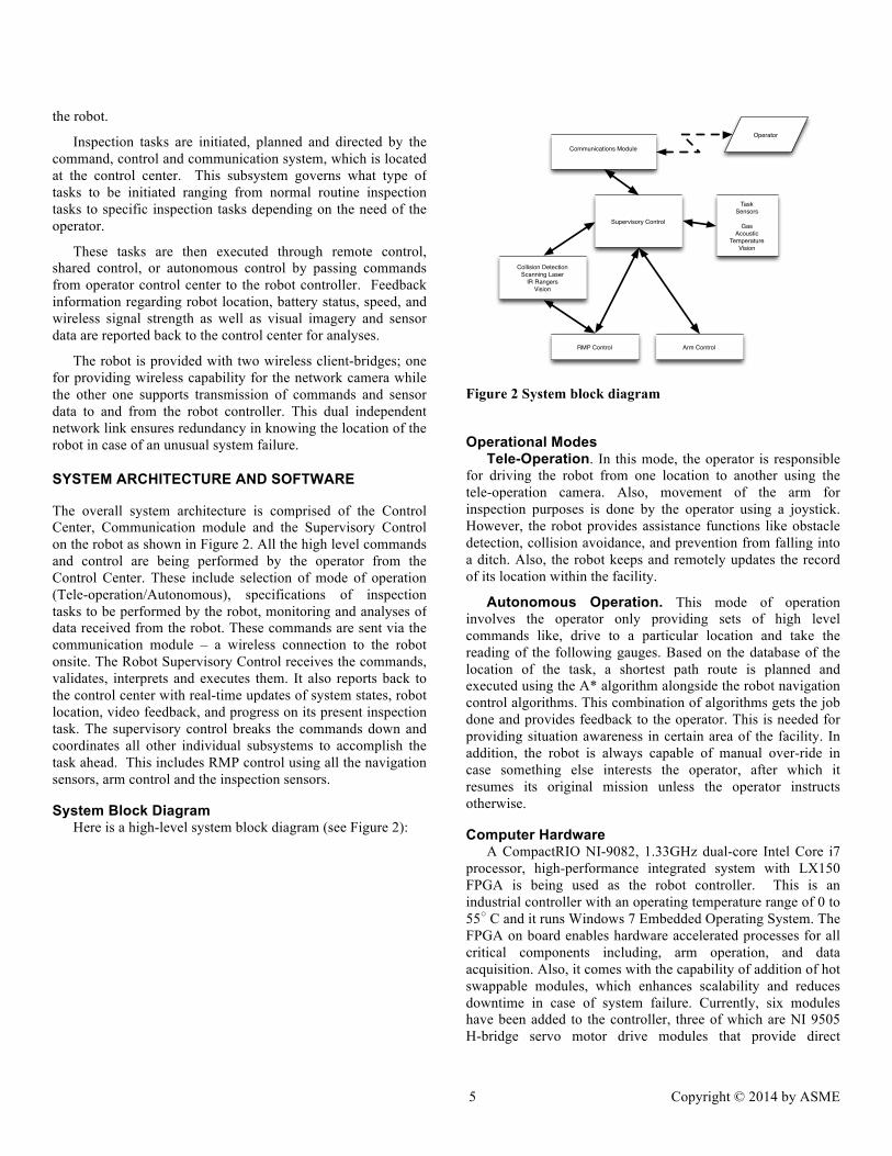
The overall system architecture is comprised of the Control Center, Communication module and the Supervisory Control on the robot as shown in Figure 2. All the high level commands and control are being performed by the operator from the Control Center. These include selection of mode of operation (Tele-operation/Autonomous), specifications of inspection tasks to be performed by the robot, monitoring and analyses of data received from the robot. These commands are sent via the communication module – a wireless connection to the robot onsite. The Robot Supervisory Control receives the commands, validates, interprets and executes them. It also reports back to the control center with real-time updates of system states, robot location, video feedback, and progress on its present inspection task. The supervisory control breaks the commands down and coordinates all other individual subsystems to accomplish the task ahead. This includes RMP control using all the navigation sensors, arm control and the inspection sensors.
System Block Diagram Here is a high-level system block diagram (see Figure 2):
Figure 2 System block diagram
Operational Modes Tele-Operation. In this mode, the operator is responsible
for driving the robot from one location to another using the tele-operation camera. Also, movement of the arm for inspection purposes is done by the operator using a joystick. However, the robot provides assistance functions like obstacle detection, collision avoidance, and prevention from falling into a ditch. Also, the robot keeps and remotely updates the record of its location within the facility.
Autonomous Operation. This mode of operation involves the operator only providing sets of high level commands like, drive to a particular location and take the reading of the following gauges. Based on the database of the location of the task, a shortest path route is planned and executed using the A* algorithm alongside the robot navigation control algorithms. This combination of algorithms gets the job done and provides feedback to the operator. This is needed for providing situation awareness in certain area of the facility. In addition, the robot is always capable of manual over-ride in case something else interests the operator, after which it resumes its original mission unless the operator instructs otherwise.
Computer Hardware A CompactRIO NI-9082, 1.33GHz dual-core Intel Core i7
processor, high-performance integrated system with LX150 FPGA is being used as the robot controller. This is an industrial controller with an operating temperature range of 0 to 55○ C and it runs Windows 7 Embedded Operating System. The FPGA on board enables hardware accelerated processes for all critical components including, arm operation, and data acquisition. Also, it comes with the capability of addition of hot swappable modules, which enhances scalability and reduces downtime in case of system failure. Currently, six modules have been added to the controller, three of which are NI 9505 H-bridge servo motor drive modules that provide direct
connectivity to the DC motors actuating the arm. Two NI 9401, 8-channel, TTL Digital / Output Modules and one NI 9201, 8-Channel, 12-Bit Analog Input Module for sensor data acquisition. The FPGA also provides the added benefit of performing low-level filtering and data processing capabilities without the need to use processor resources.
RMP CONTROL
As shown in Figure 3, the RMP is controlled using the motion control - running on the robot controller and the RMP embedded motion controller. The motion control performs the high level function of motion planning, obstacle detection, collision avoidance, path tracking, pose estimation, and logging of data using sensor data acquired from sensor suite which comprises GPS, Compass, IMU, and Laser rangefinder to determine motion commands which are sent to the RMP motion controller by continuous polling at the rate of 10Hz. As earlier said, the motion commands which include primarily linear velocity and the angular velocity are received by the RMP controller, validated and executed using its onboard controls to drive the wheels in a coordinated manner. As a form of feedback mechanism, the RMP in return transmits back its measured linear velocity and displacement, angular velocity, roll angle and pitch angles which are subsequently used in estimating the robot pose by the motion control.
Figure 3 Sensor suite used by RMP
ARM CONROL The arm control is implemented in two levels; the Intel
processor performs high-level control and trajectory generation, while the FPGA performs all the low-level state monitoring and task execution. The FPGA serves several purposes which include reading the motors' encoder counts, monitoring limit switches of each joint, and tracking the current draw of each
motor. It also runs a PID loop that adjusts the PWM of each motor to track the commanded current value from the processor.
To drive the joints to a set point, the processor obtains the present motor position from the FPGA, generates the trajectory path to the set position using linear function with parabolic blends [6]. The processor runs a PID control with feedforward that compares the present motor position to the desired position set by the trajectory generator and outputs the current (amps) value that the FPGA controller then uses to set the PWM value to send to the motors specifically to drive Joints 1, 2, and 3. Joints 4 and 5 are controlled by generating PWM pulse trains that correspond to the desired position set by the trajectory generator and tracked internally by the joint servo motors.
This controller architecture provides two major benefits, first the FPGA's provides real-time control through its high speed capability, secondly it allows for constant monitoring of motor current, motor encoder counts and limit switch states without using the processor's resources.
Reachable Workspace. Since the primary objective of the robot is to execute human worker like monitoring, the robot was designed to be able to elevate its head to a height of two meters; similar to that of a tall human. Since the robot is not required to physically manipulate objects, the horizontal workspace is only of interest in the context of being able to read gauges, sniff for gas, listen for a leak, or measure a temperature (in a future version we intend to add a vibration sensor).
Pose. The pose (position and orientation of the robot head) is of importance because the ability to read gauges and meters depends on good visual range and alignment (and good lighting). On the other hand, since the robot is not manipulating objects, five degrees-of-freedom (DOF) were deemed to be sufficient.
ROBOT KINEMATICS Since the robot is designed to be a 5DOF arm, access to all
poses within the reachable workspace is not possible. But as stated above, this is not required since the primary purpose of the robot is to sense its environment and in particular, to view and interpret objects. As a result we chose to take a different approach to the representation of the robot pose. Specifically, the descriptor to be used by the operator to describe the desired pose consists of two items: the position (x,y,z) of the wrist defined relative to the robot base (we used the intersection of Joints 1 and 2 at the shoulder) and an orientation that combines azimuth and elevation (a, e). These angles are expressed relative to the vertical and horizontal planes of the robot, respectively. Thus an orientation of (0,0) would have the head looking straight out along Link 3, in the vertical plane of the robot, and parallel with the ground plane of the mobile platform.
Equation 1 gives the homogeneous transform of Frame {5} relative to {Base}. Note that c234 = Cos(θ2 −θ3 −θ4 ) , c23 = Cos(θ2 −θ3 ) and similarly for Sin().
The frame assignments follow the Craig convention [6]. A couple of interesting things to note however about the frame assignments are the switching of the positive sense of joint rotation between Joint 2 and Joint 3. This is done so that a positive motor command unwraps the arm, i.e., causes it to extend upward. This was done so that when using the joystick controller, the operator would be driving both joints in the positive sense. Another thing to note is that the zero position for Joints 4 & 5 (which are shown in their zero positions) both reference their respective robot planes as described previously. The 3D workspace of the arm is as shown in Figure 5 below.
Figure 5 Three dimensional workspace of robotic arm
Inverse Kinematics Benefits and Limitations of 5DOF. Since the robotic
arm has only 5DOF, the description of the robot is modified to make it easier for the operator. Specifically, the inverse kinematics separate the description of the position from the description of the orientation (i.e., azimuth and elevation).
Arm Operation The arm operates under six different modes; Homing,
Parking, Standby, Joystick control, Point-to-point movement, and Command scripting mode. In homing mode, sequences of joint movements are performed to determine the joints' zero-position. As part of the built in safety feature, the operator must approve the safety of the operation or drive the arm into a safe configuration before proceeding. Moving in Joint space or the World coordinated system is performed via Joystick control or by setting a desired configuration. Due to the difficulty of parking the arm into its saddle remotely, the parking mode executes this process automatically. The standby mode ensures a halt state the arm can default into whenever there is loss of network connection. In automating inspection tasks, the command-scripting mode enables implementation of multiple pose configuration and repeated task execution.
NAVIGATION, OBSTACLE AVOIDANCE, LOCALIZATION
GPS Experiments in Industrial Environments Under clear view of the sky, GPS data are reasonably
reliable for navigation as shown in Figure 6, especially when positioning is done relative to an initial position. In this figure the robot was commanded to drive around the rectangle in the center of the photo. Different colored lines indicate the measure of position as made by the raw GPS, the pose from the Extended Kalman Filter, and a Trimble surveying GPS with RTK. However, reliability is drastically reduced near tall
To characterize the behavior of GPS sensing in an outdoor industrial environment the group traveled to a nearby coal power plant. At the plant GPS, and digital compass data was taken while moving throughout the facility. The path through the facility consisted of moving nearby large compressors, pumps, generators, and high voltage areas to see their effect on the two sensors. From this testing it was determined that these two sensors would not be sufficient for global localization in all cases and must be supplemented with other localization techniques and fiducial-based pose estimation.
Figure 6 GPS tracking result under a clear view sky
Fiducial-based pose estimation involves placing custom designed fiducials in known locations throughout the robots working environment. When the robot is in a region with fiducials it will then take pictures with the navigation cameras, and detect the targets. Only one target is needed to provide a pose estimate, however the robot is capable of using up to four for increased accuracy. Each target is encoded with its position using a QR code like encoding scheme [13]. The pose estimated from the fiducials will then be combined with current pose estimate in the robots Extended Kalman Filter. One benefit of using multiple fiducials at one location is that statistical information can be extracted from the pose estimate, this in turn increases the accuracy of the overall pose estimate from the Extended Kalman Filter [14].
Path Planning, Obstacle Avoidance, Localization and Real-time Navigation
The navigation and control of the robot is built on a hybrid approach that involves deliberative planning and reactive behavior during execution period [7]. The motion planner plans the route the robot is going to take to execute any inspection
task. This involves a global knowledge of the environment such that planning is done at a high-level. We can view the mission planner as the operator or the algorithm running on the robot depending on the mode of operation. In whichever mode, spatial-based path tracking strategy is then executed whereby the desired path is parameterized as a function of space and control actions are based on distance of the vehicle to the desired path [8]. An inertial-based Extended Kalman Filter as described in [9] alongside compass data is used to keep an accurate pose estimation of the robot by ignoring bad GPS data [16].
To evaluate the navigation algorithm, a point-to-point GPS waypoint tracking experiment was setup in an outdoor environment characterized with tall buildings similar to what could be experienced in an industrial environment. As shown in Figure 7 below, result shows good estimated robot path despite poor GPS data due to multi-path signals.
Figure 7 GPS Point to point outdoor navigation
During execution of the commands, the robot is faced with real-time challenges of its environment like obstructions on the way, hence, the need for a reactive behavior. To achieve this, the robot is equipped with a laser range finder to detect and avoid obstacles. Based on an obstacle threshold distance of 3.5m, the obstacle avoidance algorithm which is loosely based on Vector Field Histogram obstacle avoidance algorithm [10] continuously checks if there is any obstacle within the present path way of the robot. If there is none, it continues to execute the pre-planned route. However, if an obstacle appears within the range of its trajectory, the robot reduces its velocity as a function of its closeness to the obstacle, calculates and drives towards a free space that is wide enough and that is in the direction closest to the goal. While maneuvering around the obstacle, it keeps choosing directions closest to the goal until there is actually an accessible free space in that direction.
COMMUNICATION For a robotic system to be operated remotely, there
must exist a way to communicate over some, possibly large, distance. For effective communication, minimum bandwidth requirements must be met. We have chosen to use Wi-Fi for wireless communication in the refinery since many of the signal protocols needed are well developed and the infrastructure is in place.
Wi-Fi Signal Propagation Properties We have performed a number of experiments to determine a
correlation between received signal strength indicator (RSSI), bandwidth, distance, transmission power and mobility in various environments such as inside our office building, in a soccer field, and in a power plant. The results show the upper and lower bound signal characteristics of our equipment, including RSSI, bandwidth, and link quality. A transmission power of 11 dbm will require a multitude of units because its bandwidth drops to near 0 Mbps within 30 m, while a transmission power of 29 dbm will cause interference as it is capable of transmitting well over 90 m with a bandwidth over 5 Mbps. These findings were determined using the EnGenius ENH 210EXT access point (AP).
Wi-Fi AP Deployment In order to ensure communication between the offsite
control station and the robot, we must provide complete coverage of the given environment. We have developed a heuristic that will determine single coverage of the environment while minimizing the number of APs needed. The results from the signal propagation experiments are used to determine how a newly added AP affects signal propagation – we have considered two metrics for this heuristic. The first metric uses the average minimum distance between all uncovered nodes to determine the best placement of an access point (AP) for each iteration as described in [11]. The second metric uses the total number of new nodes covered by the placement of the new AP as described in [12]. From the results of our experiments, we find that the minimum average distance metric uses fewer APs to cover a given environment.
The offsite control station and the robot use a heartbeat communication protocol over TCP/IP. In this protocol, state, location, and sensor information is communicated. The system design is considered to be robust, i.e. it is capable of dropping five consecutive packets before the system flags a communication error. If a communication error does occur, the robot stops moving and waits for communication to be re-established.
Wi-Fi Localization Since Wi-Fi access points (AP) deployed in the refinery will
not only be used for communication, but also used for localization of the mobile robot, we have extended the single coverage AP placement heuristic to consider k-Coverage. In other words, every point in the region of interest is covered by at least k access points. To perform localization through triangulation using RSSI fingerprinting, k needs to be at least 3. A fingerprint consists of readings from every AP within reach
and the current location that the fingerprint is taken from. We will first build a database of fingerprints in the environment for comparison. We will then compare this database to the current fingerprint in order to determine our location estimate. This information is then integrated with the Kalman Filter to increase the accuracy of robot localization.
OPERATOR INTERFACE AND MISSION CONTROL We envision several different modes of operation for the
robot based on the needs and desires of the operator and what is needed to support plant operations. In “standard” mode, the robot could be programmed to complete a set of “rounds” requiring it to visit several predefined locations and to execute specific tasks at these locations, e.g., read a gauge, or record a temperature, listen for acoustic signatures, and sniff for gas. It could also do thermography of important components, e.g., pumps, circuit breakers, valves, heat exchangers, or compressors. Using its predefined database of acceptable states, it could then decide whether notification of the operator is required or to simply log the results and carry on. We refer to this as autonomous mode. It would be the responsibility of the operator to define the route, the tasks and the conditions under which immediately notification is required.
Control Modes • Remote Control: Full human involvement with
decoupling of joystick input
• Autonomous Control: Full machine involvement with human supervision
• Shared Control: Machine operation with direct human input optional
During tele-operation, the user is provided with full control of the robot; however, the robot also provides some functionality for safe navigation by the operator. Some of the shared tasks handled by the robot is to detect obstacles and reduce its velocity as a function of its closeness to the obstacle. Since, a skid steering platform is being used, the collision avoidance was developed to assist the operator from running into obstacles by its sides as well as its front. For example, when driving through a narrow path, the robot automatically reduces its speed drastically so that maneuvering can be done easily. Also, when turning in place or negotiating a tight bend, the angular velocity of the robot is reduced as a function of its closeness to the obstacles by its sides as shown in Figure 8. As part of sharing the control, the robot was initially given control to choose the direction to drive towards when encountering obstacles, however, when no goal is defined, this functionality sometimes conflict with the operator intension since there is no pre-planned route.
Mechanical Integration The robotic arm assembly was designed to be easily
integrated with the RMP. The robotic arm assembly can be positioned by two people on top of the RMP and easily fastened with twelve bolts. The robotic arm assembly can then be connected electronically to the RMP via the attachment of several cables that run through a cable tray connected to the robotic arm assembly.
SYSTEM TESTING
Bearings, Noise and other joyful experiences J As previously mentioned, the same DC motors where used
for joints 1, 2 and 3, this helped simplify the design process but also the integration process. This motor mount only had to be tested once, and afterwards could be used for the three joints confidently. After the robotic arm had been assembled and disassembled several times it was decided that a further attempt to minimize hardware would be made by replacing traditional nuts with captive nuts. Captive nuts behave like regular nuts, but grips into the material and remains permanently fixed to the part. It was also noticed that the keys used to couple motor drive shafts to gearboxes could slide out of position and inhibit motor motion. To address this problem the keys and key shafts were scored and epoxied together. Electrical noise was initially an issue while testing the system as whole. However, this was solved by implementing good grounding procedures.
Mechanical Room Tests In order to evaluate the operational capability of the robot in
an environment similar to the one it will be deployed to, experiments were conducted in the mechanical room of our engineering building. Figure 10 are photographs of the robot at work in this facility. While a refinery is an outdoor environment, a mechanical room for a large building shares many of the same attributes: lots of piping, numerous pressure vessels, fluid pumps, heat exchangers, etc. The robot’s task is
to travel to a defined location, identify a feature of interest, e.g., a pressure gauge, move to a pose that allows the sensors (camera) on the robot to gather data (pressure reading) and transmit this back to the operator.
Figure 9 Robot traveling in mechanical room
Figure 10 Robot viewing gauge
Tests were conducted that required the operator to drive the
robot through a restricted pathway to a desired location, switch to arm control mode and position the head of the robot so that a gauge could be read. This process was repeated several times with success. It was observed that driving the robot remotely is a challenging task if one has to rely only on the video stream from the robot. This is due, in part, to the lack of context for the motion, i.e., not being able to see the obstacles around you (on the sides) and having to judge the distance to obstacles in a 2D image, requires more focus and care.
Once the robot platform was positioned near the feature of interest, the second part of these tests was the maneuvering of the robot arm into an appropriate pose so that the gauge could be read by the operator. This was accomplished but often required the operator to jump between moving the arm linkages (Joints 1,2,3) and the orientation of the head. This was primarily due to the need / desire to have the head aligned with the normal (vector) of the gauge face to facilitate better viewing of the information on the gauge.
Future Testing Experiments at the PI. The robot has now been
transferred to the Petroleum Institute in Abu Dhabi[13]. Once it has been reassembled, experiments will be conducted to do navigation using GPS, dead reckoning, and Wi-Fi localization, as described previously. In addition, indoor navigation will be tested in remote control, shared control and autonomous mode. Arrangements are being made to do testing in a nearby refinery to further our understanding of the influence of refinery infrastructure on the use of GPS and Wi-Fi communications and localization. The goal will be to quantify the error that this infrastructure has on these sensors, and to develop algorithms for addressing these issues.
CONCLUSIONS The integrated system works. We are pleased with the
level of performance achieved to date, and have found the hardware and software to be robust enough to deal with the disturbances encountered in real-world environments. The software development environment has provided the support needed to implement a multi-faceted command and control infrastructure (remote control, shared control, and autonomous control).
Needed enhancements. One facet that has gotten our attention is the need for a robust Wi-Fi infrastructure. When there has been significant interference on the network, remote control operations are severely limited, since there a safety need to maintain validation of the communication link in order to have the robot continue to operate. On a few occasions when a reliable link could not be maintained, operations were shut down. This is an area for further work. In addition, mapping database, and pose planning for inspection operations will be developed over the next several months.
ACKNOWLEDGMENTS Put acknowledgments here.
REFERENCES [1] David A. Anisi, Johan Gunnar, Tommy Lillehagen and
Charlotte Skourup, Robot Automation in Oil and Gas Facilities: Indoor and Onsite Demonstrations, The 2010 IEEE/RSJ International Conference on Intelligent Robots and Systems, October 18-22, 2010, Taipei, Taiwan
[2] Matthias Bengel, Kai Pfeiffer, Birgit Craf, Alexander Bubeck, and Alexander Verl, Mobile Robots for Offshore Inspection and Manipulation, The 2009 IEEE/RSJ International Conference on Intelligent Robots and Systems, October 11-15, 2009, St. Louis, USA
[3] H. Choset, K Lynch, S. Hutchinson, G. Kantor, W. Burgard, L. Kavraki, S. Thrun, “ Principles of Robot Motion: Theory, Algorithms, and Implementations, 2005, MIT Press, ISBN 978-0-262-03327-5.
[4] SINTEF. "Robots Taking Over The Job On Offshore Oil Drilling Platforms." ScienceDaily. ScienceDaily, 1 January 2008. <www.sciencedaily.com/releases/2007/12/071221230852.htm>
[5] Akbar F. Moghaddam, Magnus Lange, Omid Mirmotahari and Mats Høvin, “Novel Mobile Climbing Robot Agent for Offshore Platforms”, World Academy of Science, Engineering and Technology 68 2012.
[6] John J. Craig, Introduction to Robotics: Mechanics and Control, 3rd Ed, Pearson Prentice Hall, 2005
[7] F. Qureshi, D. Terzopoulos, and R. Gillett, “The Cognitive Controller : A Hybrid , Deliberative / Reactive Control Architecture for Autonomous Robots.” 17th International Conference on Industrial and Engineering Applications of Artificial Intelligence and Expert Systems, IEA/AIE 2004, Ottawa, Canada, pp 1102-1111 May 17-20, 2004.
[8] K. L. Moore, “A Tutorial Introduction to Autonomous Systems,” Proceedings of the 17th World Congress, The International Federation of Automatic Control, pp. 11720–11731, Jul. 2008.
[9] S. Panzieri, F. Pascucci, and G. Ulivi, “An Outdoor Navigation System Using GPS and Inertial Platform,”IEEE/ASME Transactions on Mechatronics, vol. 7, no. 2, pp. 134–142, 2002.
[10] J. Borenstein, Y. Koren, “The Vector Field Histogram –Fast Obstacle Avoidance for Mobile Robots,”IEEE Journal of Robotics and Automation, vol. 7, no. 3, pp. 278–288, 1991.
[11] David Plets, Wout Joseph, Kris Vanhecke, Emmeric Tanghe, Luc Martens, "On Coverage Prediction and Optimization Algorithms for Indoor Environments,"
EURASIP Journal on Wireless Communications and Networking 2012 (123), 2012.
[12] Guillaume de la Roche , * Katia Jaffrès-Runser and Jean-marie Gorce, "On predicting in-building WiFi coverage with a fast discrete approach," (2007), Int. J. of Mobile Network Design and Innovation, Vol.2, No.1, pp.3 - 12, 2007.
[13] Petroleum Institute, http://www.pi.ac.ae/index.php, accessed April 14, 2014.
[14] U. Sinha ”Scanning QR Codes” http://www.aishack.in/2012/02/scanning-qr-codes/2/
[15] Hoff, W. A. and T. Vincent, “Analysis of Head Pose Accuracy in Augmented Reality,” IEEE Trans. Visualization and Computer Graphics, Vol 6., No. 4, pp. 319-334, 2000.
[16] S. Sukkarieh, E. M. Nebot, and H. F. Durrant-whyte, “A High Integrity IMU/GPS Navigation Loop for Autonomous Land Vehicle Applications, IEEE Transactions on Robotics and Automation” vol. 15, no. 3, pp. 572–578, 2006.