Development of an Ultra-High Pressure Deep Water Riser/Flowline – Challenges and Progress Innovation in Extreme Environment Technologies: High Pressure & Temperature Thursday, April 10, 2014 Michelle Davidson Andrew Roberts Peter Kirton Andrew Thompson Principal Engineer Chief Engineer Project Manager Senior Polymer Engineer Neville Dodds George Karabelas Principal Engineer VP-Technology (UK) NPI Team Suranjith Warnakulasuriya Iwan Harries David Lambert Mark Laycock Majid Al-Zubaidy GE Public Upul S Fernando Principal Engineer, Group Leader R&D
Transcript
Development of an Ultra-High Pressure Deep Water Riser/Flowline – Challenges and Progress
Innovation in Extreme Environment Technologies: High Pressure & Temperature Thursday, April 10, 2014
Michelle Davidson Andrew Roberts Peter Kirton Andrew Thompson Principal Engineer Chief Engineer Project Manager Senior Polymer Engineer
Neville Dodds George Karabelas Principal Engineer VP-Technology (UK)
NPI Team Suranjith Warnakulasuriya Iwan Harries David Lambert Mark Laycock Majid Al-Zubaidy
GE Public
Upul S Fernando Principal Engineer, Group Leader R&D
2 GE Title or job number
3/12/2014
Unbonded Flexible Pipe
Pipe consists of concentric layers of metallic wires,
tapes and extruded
polymers
Designed to form a
structure that addresses the specific loads,
environmental
requirements and
characteristics of the
transported fluids
End fittings are custom designed.
Each layer of the pipe individually terminated. Designed to assure
Structural integrity Tension – weight Pressure / bending Temperature Dynamic service - fatigue Riser interaction Installation Clashing Interference Entanglement
Touch down point Abrasion Local armour buckling (bird-caging)
Specific analyses Global analysis Local analysis Armour stress analysis Gap span Corrosion fatigue End fitting analysis
Riser
Flowline
Pipe Connection
Market Demand
0
400
800
1200
0
5
10
15
20
1980 2000 2020
(ba
r)
De
sig
n P
ress
ure
(kp
si)
0
1
2
3
1980 2000 2020
Wa
ter
De
pth
(km
)
Fluid medium
Oil & gas (mixture)
Increasingly sour
H2S, permeated gas
Rapid depressurisation
-50
0
50
100
150
1980 1990 2000 2010 2020
Op
era
tin
g T
em
p (o
C)
Maximum
Minimum
Structural integrity Pressure/bending -static service Temperature
4 GE Title or job number
3/12/2014
Flexible pipes for high pressure & deep water Only need a flexible tube (fluid barrier) !!!
1. Carcass (Flexbody ™)
2. Pressure Armour (Flexlok ™ / Flexpress ™)
Prevent buckling of polymer tube under external pressure Limits water depth Limits the diameter
Key design features Strength, durability & integrity Temperature performance, Aging behaviour, Fluid compatibility
Prevent bulging of polymer tube under internal pressure. Limits design pressure Limits the diameter Can be multi layer Need Sacrificial layer for high pressure
3. Tensile Armour (Flextensile ™) Prevent extension of polymer tube under weight/axial load. Limits water depth Several wires Multi-layered Fatigue resistance (sweet/sour)
4. Anti-wear Layers (Flexwear ™)
5. End Fittings - Leak free fluid barrier seal
Termination of carcass, pressure armour and tensile armour wires
6. Installation Requirements
Prevent rubbing between metal layers Limits pressure Fatigue durability Annulus Conditions
GE Public
5 GE Title or job number
3/12/2014
Aim of the Project Development of a 4 inch (100 mm) diameter riser/flowline for 20kpsi (1200 bar) design
pressure and 3 km water depth to operate at 100oC maximum temperature and to
transport gas/fluid under mild sour conditions
• Maintaining the integrity of the polymer barrier
Withstand rigorous service temperature and pressure. Compatibility of barrier with service fluids under high pressure
Ensuring barrier integrity during service life, thermal cycling, shut-down
• Design of a suitable carcass to resist wet collapse at ultra-deep water
• Selection of metallic hoop armour layers to resist high internal pressure
• Limiting the weight of the pipe and achieving necessary axial stiffness/strength
• Evaluation of layer interaction in two pressure armour layer design
• Development of end fittings with proven seal integrity
• Completion of FAT and offshore field tests without any detrimental effect on pipe
• Achieving necessary bending requirements and packaging
• Ensure damage free dynamic interactions between metal layers
• Safeguard integrity of the pipe under rapid depressurization conditions
• Satisfy Industry design standards (ISO 13628-2)
Key Technical Challenges
GE Public
6 GE Title or job number
3/12/2014
Developing HP & HT Barrier - Challenges
Material - Depends on service temperature : below 60oC – PA or PE and above 60oC PVDF (or PEX/PPS)
Design Criteria (API 17J) - Static (flowline) require ±7% few cycles + 7% strain for 25 year service
Polymer crazing at high hydrostatic stress Rapid Gas Depression (RGD)
Crazing can occur in places of high local Plastic strain if not controlled through design, materials or mitigated through treatment.
Blistering can occur in some materials if depressurisation rates exceed certain limits.
GE Public
Typical Crazing
Blisters due to RGD
7 GE Title or job number
3/12/2014
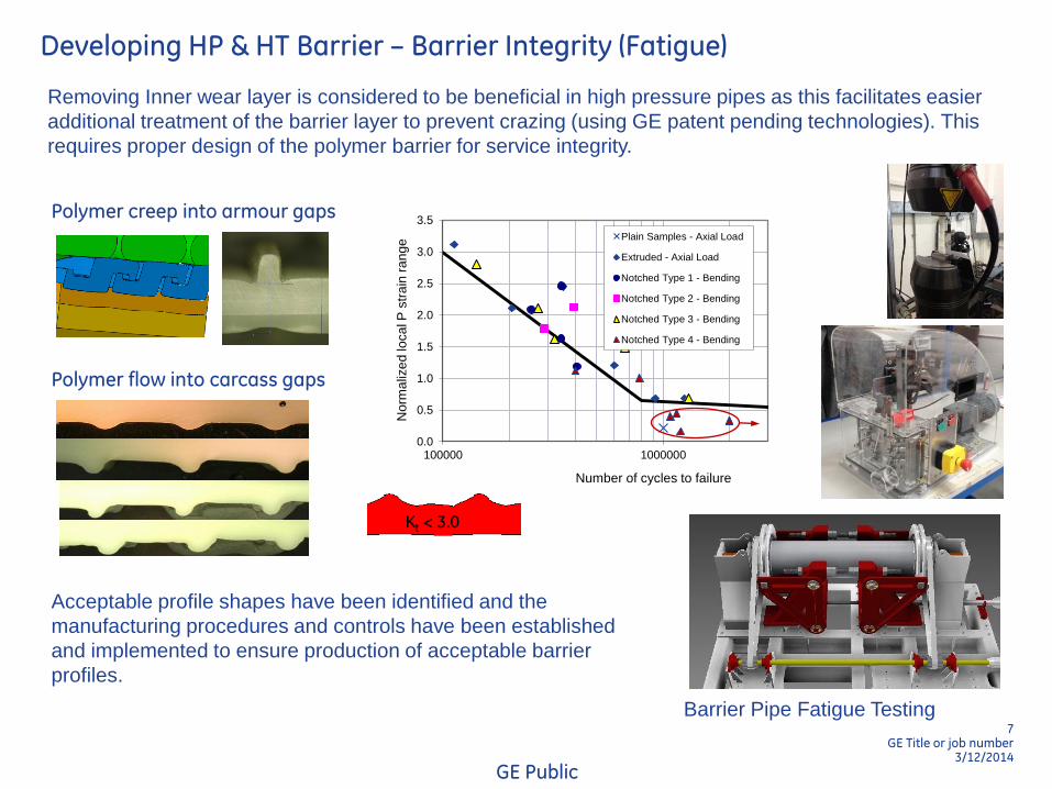
Developing HP & HT Barrier – Barrier Integrity (Fatigue)
Polymer creep into armour gaps
Kt < 3.0
Acceptable profile shapes have been identified and the
manufacturing procedures and controls have been established
and implemented to ensure production of acceptable barrier
profiles.
Removing Inner wear layer is considered to be beneficial in high pressure pipes as this facilitates easier
additional treatment of the barrier layer to prevent crazing (using GE patent pending technologies). This
requires proper design of the polymer barrier for service integrity.
0.0
0.5
1.0
1.5
2.0
2.5
3.0
3.5
100000 1000000
Norm
aliz
ed
lo
ca
l P
str
ain
ra
ng
e
Number of cycles to failure
Plain Samples - Axial Load
Extruded - Axial Load
Notched Type 1 - Bending
Notched Type 2 - Bending
Notched Type 3 - Bending
Notched Type 4 - Bending
Polymer flow into carcass gaps
GE Public
Barrier Pipe Fatigue Testing
8 GE Title or job number
3/12/2014
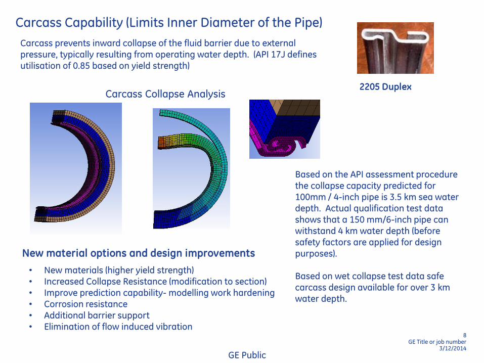
Carcass Capability (Limits Inner Diameter of the Pipe)
New material options and design improvements
• New materials (higher yield strength) • Increased Collapse Resistance (modification to section) • Improve prediction capability- modelling work hardening • Corrosion resistance • Additional barrier support • Elimination of flow induced vibration
2205 Duplex
Carcass prevents inward collapse of the fluid barrier due to external pressure, typically resulting from operating water depth. (API 17J defines utilisation of 0.85 based on yield strength)
Based on the API assessment procedure the collapse capacity predicted for 100mm / 4-inch pipe is 3.5 km sea water depth. Actual qualification test data shows that a 150 mm/6-inch pipe can withstand 4 km water depth (before safety factors are applied for design purposes). Based on wet collapse test data safe carcass design available for over 3 km water depth.
GE Public
Carcass Collapse Analysis
9 GE Title or job number
3/12/2014
Pressure Armour Capacity
Function of the pressure armour is to resist internal & external pressure and give strength in the hoop direction during manufacture, installation and operation. Provide a guard against creep extrusion of the polymer.
Utilisation depends on load case
Based on available carcass design for 3 km water depth maximum pipe internal diameter is limited to 150 mm. Due to manufacturing limitations the pressure armour wire thickness needs to be below 12 mm. Single pressure armour (8 mm and 10 mm) insufficient to achieve design pressure of 15kpsi Dual pressure armour required - 8 (+ 8) mm wire scan give 15 kpsi 10 (+10) mm wires can give 20 kpsi
Limit by
carcass 8 mm Wire
10mm Wire
Two Layer
8mm Wire
Two Layer
10mm Wire
Limit by
Wire size
HP Design Criteria
Dual pressure armour design
Hoop stress at FAT
Hoop stress at P DESIGN
GE Public
10 GE Title or job number
3/12/2014
Tensile Armour Capacity
Hoop - OK
Tensile – Not Acceptable
2 Armour
Touchdown zone
Tensile wire buckling resistance is also a consideration. The minimum bend radius of the pipe depends on water depth.
Multiple helically formed wires - Support axial load (mainly due to weight. Pairs of contra-wound layers to give torsional stability. Lay angle optimised during pipe design to balance axial capacity and hoop strength, giving additional support to the pressure armour layer.
The high strength requirements coupled with the suspended riser length result in a very heavy structure and corresponding high topside loads.
Deep
Water
3 km
High
Pressure
20 kpsi
Tensile + Hoop
Strength
New Materials
Established Materials
Tensile – OK
Hoop - OK
4 Armour
Not ideal,
significant buoyancy required
2 Armour
buoyancy or split riser design
Tensile – OK
Hoop - OK
4 Armour
Tensile – OK
Hoop - OK
11 GE Title or job number
3/12/2014
Buoyancy Requirements of HP Deep Water Pipes
2 Tensile Armour Design – New Materials (2 x 90 tonnes buoyancy)
4 Tensile Armour Design Current Materials (2 x 214 tonnes buoyancy)
Top Tension Allowable Tension (~Installation Limit)
Top Tension with stepped buoyancy
New Armour Materials
Alternatives to the current carbon-manganese steels:
Required Properties, Mechanical strength, weld and corrosion properties Confirm potential ‘improvement’ in capability using design software Ability to form and deliver suitable wires to the required profile Ability to wrap and weld using available manufacturing machines Technical and economic feasibility.
Midline buoyancy section (GE patented)
Arc-length
12 GE Title or job number
3/12/2014
Seal ring is plastically deformed creating highly localized contact pressure at the contact edge.
Outer taper of seal ring engages with the inner taper of the end fitting body.
R S
High Pressure End Fitting
End fitting is an essential component of flexible pipes enabling their connection between moving structures and pipes to make complete pipe infrastructure.
Before swaging
Barrier Seal
Maximum contact pressure at the interface changes with applied internal pressure
Maximum contact pressure must be greater than leak criteria to maintain a seal
New end fitting designs proven to work above 30 kpsi
GE Public
After swaging
Key Functions - Effective barrier seal Termination of all layers Anchoring tensile amour Transfer of external loads
13 GE Title or job number
3/12/2014
Anti-Wear Tapes
Anti-wear tape layers are used to prevent direct contact between the reinforcement layers. The contact stresses in HP pipes are significantly high, leading to an increased risk of fretting or contact fatigue of the metallic wires.
Typical deformation in wear tapes
In flowlines these tapes are subjected to static non-uniform compression whist in risers these may be subjected to compression loading with dynamic slip.
Tape testing facility New Tape Material High performance materials Interlayer interaction – friction, wear, damage mechanisms Wear models – prediction of service life Environmental effects – temperature, annulus conditions New experimental facilities
GE Public
14 GE Title or job number
3/12/2014
Composite Pipe Design
Composite Smoothbore
Composite with metal Carcass
Reduction of A B Mass/Top Tension 60% 55%
200 mm/ 8 inch ID Pipe. 15% OD reduction
Composite Armour - Optimized fiber angles and
thicknesses to meet design requirements
Bonded Liner/Barrier - PVDF - with high
chemical resistance; reduced permeated gas risks
Thermoplastic Matrix - PVDF - qualified material
Carbon Fiber - Not susceptible to environmental
stress corrosion; chemically resistant
Flow Induced Pulsation
New design technology has been used to develop pulsation free carcass profiles (GE patents pending)
Flow induced pulsation can effects the dynamic performance of the pipe. This is pronounced when transporting gas in deep water pipes.
Condition Monitoring
the MAPS® wire stress and wire break monitoring and inspection systems, integrated fibre optic sensors embedded within the pipe structure, and topsides equipment for the monitoring of polymer and pipe annulus condition.
GE Public
15 GE Title or job number
3/12/2014
Summary - Key Challenges & Progress
Resist internal pressure
(Flexlok)
Existing Technology
Comply with design
standards
Burst/design
pressure ratio
Prevent
collapse
(carcass)
Manage
tensile
capability
New Technology Developments
Passing FAT
and offshore field tests
Manage
interaction
between layers
Rapid
depressurisation
(multilayer barrier)
Packaging
and bending
limits
Managing weight and
strength
Achieve seal
performance
Future Developments
High pressure ultra-deep
water flexible pipe
Integrity of
end fittings
High pressure
design
strategy
Validate
dynamic
performance
Integrity of
polymer
barrier
GE Public
END - Any Questions ?
Acknowledgements - GE Oil & Gas - Deepstar Programme - Sheffield University, UK - RPSEA Programme