Development of Mathematical Model Using DOE for Analyzing Angular Distortion of 202 Grade Stainless Steel GTAW Plates R. Sudhakaran & Dr. V. VeL Murugan Dept of Mechanical Engineering Kumaraguru College of Technology Coimbatore
Transcript
Development of Mathematical Model Using DOE for Analyzing Angular
Distortion of 202 Grade Stainless Steel GTAW Plates
R. Sudhakaran & Dr. V. VeL MuruganDept of Mechanical Engineering
Kumaraguru College of Technology
Coimbatore
Angular Distortion
• Angular distortion is a major problem and most pronounced among different types of distortion in the butt welded plates.
• In arc welding processes, due to rapid heating and cooling the work piece undergoes an uneven expansion and contraction in all the directions. This leads to distortion in all the directions of the work piece.
To Remove Angular Distortion
• Arrest the work piece in a base plate
• Pre bend
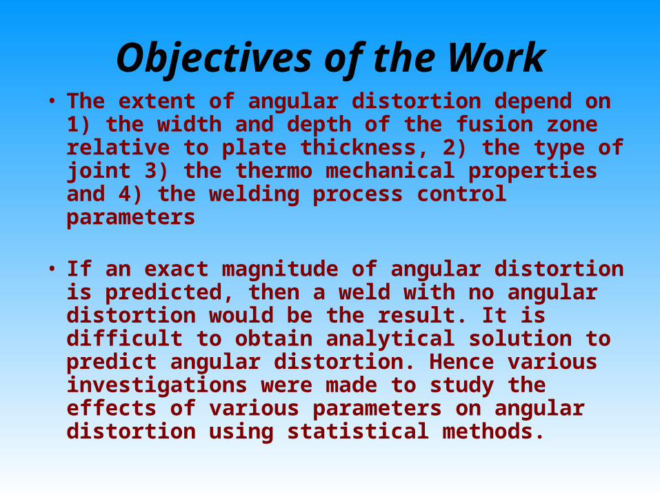
Objectives of the Work• The extent of angular distortion depend on
1) the width and depth of the fusion zone relative to plate thickness, 2) the type of joint 3) the thermo mechanical properties and 4) the welding process control parameters
• If an exact magnitude of angular distortion is predicted, then a weld with no angular distortion would be the result. It is difficult to obtain analytical solution to predict angular distortion. Hence various investigations were made to study the effects of various parameters on angular distortion using statistical methods.
Objectives of the Work
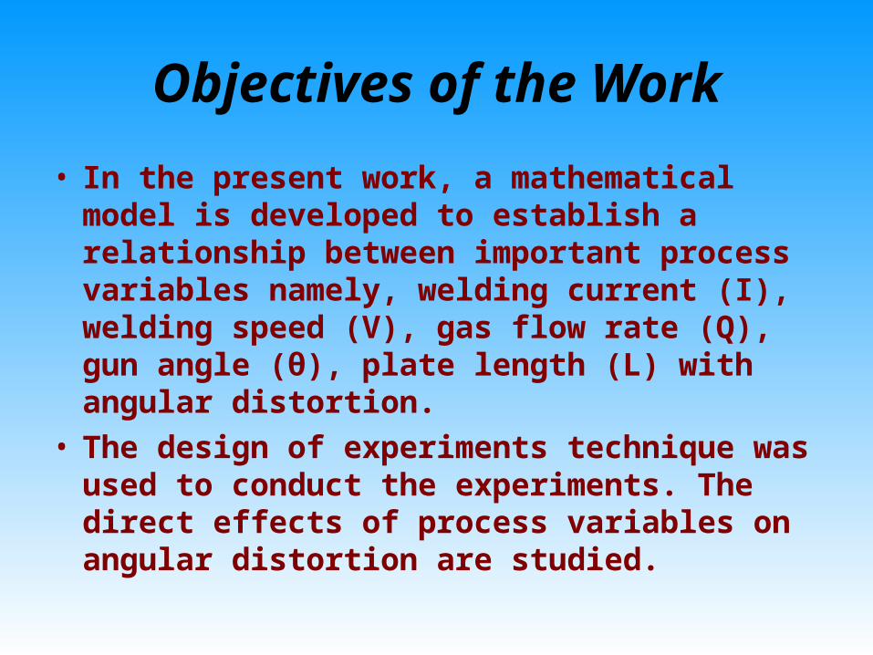
• In the present work, a mathematical model is developed to establish a relationship between important process variables namely, welding current (I), welding speed (V), gas flow rate (Q), gun angle (θ), plate length (L) with angular distortion.
• The design of experiments technique was used to conduct the experiments. The direct effects of process variables on angular distortion are studied.
Experimental Procedureo The experiments were
conducted using Lincoln V 350 Pro Electric Digital Welding Machine.
o A servo motor driven manipulator was used to maintain uniform welding speed.
Experimental Procedure
• The welding gun is held stationary in a frame above the table and it is provided with an attachment for setting the required welding gun angle.
• Argon is used as the
shielding gas and its flow rate is varied for each experiment as per the requirements.
Plan of WorkIdentifying the process variablesIdentifying the process variables
Developing the design matrixDeveloping the design matrix
Conducting the experiments as per the design matrixConducting the experiments as per the design matrix
Development of mathematical modelsDevelopment of mathematical models
Evaluation of coefficients of the modelsEvaluation of coefficients of the models
Checking adequacy of the modelsChecking adequacy of the models
Testing the regression coefficients of the modelsTesting the regression coefficients of the models
Validation of the mathematical modelsValidation of the mathematical models
Analyzing the Analyzing the results results
Limits of Process Variables
• The angular distortion is a function of many independently controllable process parameters such as welding current (I), welding speed (V), gas flow rate (Q), gun angle (θ), plate length (L)
• The design plan was decided based on the practical considerations for the system
Factor Upper limit
Lower limit
Welding current (I)
amps
110 70
Welding speed (V)
mm/min
120 80
Gas flow rate (Q) liter/min
25 5
Gun Angle (θ)
Degrees
90 50
Plate Length (L) mm
200 100
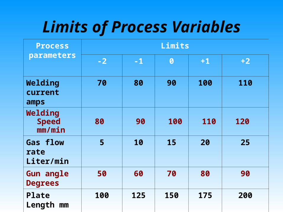
Limits of Process VariablesProcess
parametersLimits
-2 -1 0 +1 +2
Welding current amps
70 80 90 100 110
Welding Speed mm/min
80 90 100
110 120
Gas flow rateLiter/min
5 10 15 20 25
Gun angle Degrees
50 60 70 80 90
Plate Length mm
100 125 150 175 200
Design Matrix
The design matrix chosen to conduct the experiments was five factor, five levels central composite rotatable designs consisting of 32 sets of coded conditions .
This design matrix comprises a full replication factorial design i.e. 24 = 16 factorial design plus 7 center points and 8 star points.
Recording of Angular Distortion
The angular distortion was determined using Microscribe G2 coordinate measuring machine. The angle β between the two lines was measured. From the angle β the angle α was determined using the equation
2)180(
Evaluation of Regression Coefficients
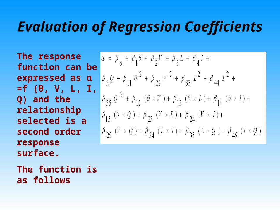
The response function can be expressed as α =f (θ, V, L, I, Q) and the relationship selected is a second order response surface.
The function is as follows
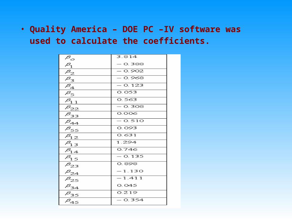
• Quality America – DOE PC –IV software was used to calculate the coefficients.
Development of Mathematical Model
• Insignificant coefficients were dropped along with the parameters with which they are associated.
• This was carried out by conducting backward elimination analysis with t- probability criterion kept at 0.75
• The final mathematical model is as follows
Validity of The Model
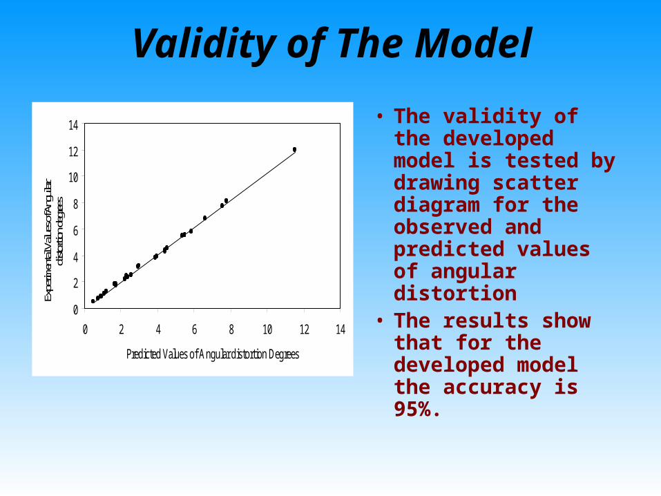
• The validity of the developed model is tested by drawing scatter diagram for the observed and predicted values of angular distortion
• The results show that for the developed model the accuracy is 95%.
0
2
4
6
8
10
12
14
0 2 4 6 8 10 12 14
Predicted Values of Angular distortion Degrees
Expe
rimen
tal V
alues
of A
ngul
ar di
storti
on de
gree
s
Adequacy of The Model• The adequacy of the model was
tested using the Analysis of Variance Techniques
SS sum of squares, DOF degree of freedom
Mean sum of squares = sum of square terms/DOF
F ratio = MS of lack of fit/ MS of error terms
R ratio = MS of first order term & second order term/ MS of error term
F ratio (6, 5, 0.05) = 4.95
R ratio (20,5, 0.05) = 4.56
Results and Discussion
• The mathematical model given above can be used to predict the angular distortion by substituting the values of the values of the respective process parameters.
• The direct effects of the process parameters on angular distortion are discussed below.
0
1
2
3
4
5
6
7
8
50(-2) 60(-1) 70(0) 80(1) 90(2)
Gun Angles Degrees
Angula
r D
isto
rtio
n D
egre
es
V = 100 mm/minL = 150 mmI = 90 Amps
Q = 15 Lit/min
0
0.5
1
1.5
2
2.5
3
3.5
4
4.5
5
80(-2) 90(-1) 100(0) 110(1) 120(2)
Welding Speed mm/min
An
gu
lar D
isto
rti
on
De
gre
es
θ =70 °V = 100 mm/minL = 150 mm
Q = 15 Lit/min
Results and Discussion
0
1
2
3
4
5
6
7
100(-2) 125(-1) 150(0) 175(1) 200(2)
Plate Length mm
An
gu
lar
Dis
tort
ion
De
gre
es
θ = 70°V = 100 mm/minI = 90 Amps
Q = 15 Lit/min
0
1
2
3
4
5
6
70(-2) 80(-1) 90(0) 100(1) 110(2)
Welding Current Amps
An
gu
lar
Dis
tort
ion
De
gre
es
θ = 70°V = 100 mm/minL = 150 mm
Q = 15 Lit/min
3.4
3.5
3.6
3.7
3.8
3.9
4
5(-2) 10(-1) 15(0) 20(1) 25(2)
Gas Flow Rate Litre/Min
Ang
ular
Dis
tort
ion
Deg
rees
θ = 70°V = 100 mm/minL = 150 mmI = 90 Amps
Conclusions
• The second order quadratic model can be effectively used to predict angular distortion in gas tungsten arc welding of stainless steel 202 grade plates.
• Central composite design can be conveniently used to analyzing the direct effects of different combinations of process parameters within the range of investigation on the angular distortion of gas tungsten arc welded stainless steel 202 plates.
Conclusions
• The predicted angular distortion is compared with the experimental one and the deviations falls within the limit of 95% confidence level.
• The maximum angular distortion is 12° when all the process parameters are maintained at -1 level and welding speed is maintained at +1 level.
• Out of the five process parameters selected for investigation, welding current has strong effect on angular distortion; plate length and gas flow rate has a negative effect on angular distortion