1 Development of Modeling Approaches for Nuclear Thermal Propulsion Test Facilities D. Jones, D. Allgood, K. Nguyen and D. Coote NASA John C. Stennis Space Center Engineering and Test Directorate Nuclear and Emerging Technologies for Space (NETS) Conference Infinity Science Center, Mississippi February 24-26, 2014 https://ntrs.nasa.gov/search.jsp?R=20140002219 2019-08-29T15:04:20+00:00Z
Transcript
1
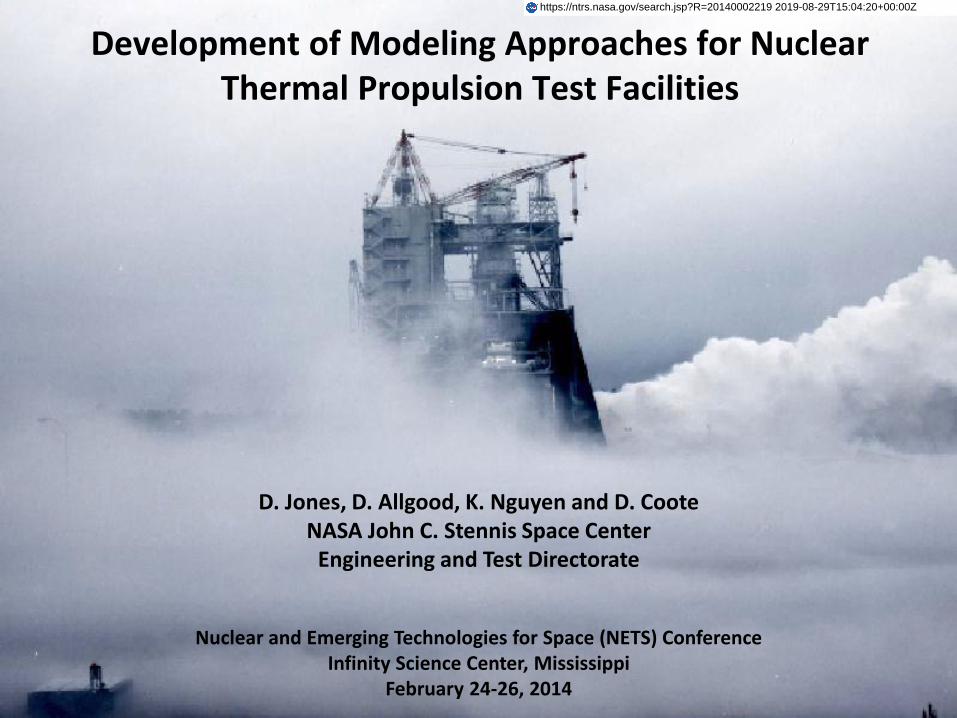
Development of Modeling Approaches for Nuclear Thermal Propulsion Test Facilities
D. Jones, D. Allgood, K. Nguyen and D. Coote NASA John C. Stennis Space Center
Engineering and Test Directorate
Nuclear and Emerging Technologies for Space (NETS) Conference Infinity Science Center, Mississippi
24Feb14 Development of Modeling Approaches for Nuclear Thermal Propulsion Test Facilities - 3028
6
NASA/SSC’s Participation in Nuclear Thermal Propulsion Technology Development
• SSC’s Office of Chief Technologist has provided funding since FY05 via its Center Innovation Funding (CIF) budget to investigate two NTP engine test exhaust processing approaches. ‐ Non-Nuclear NTP engine technology development (FY05,06,12). ‐ Direct gas treatment (effluent scrubbing) (FY13). ‐ Total exhaust containment (FY14).
• Goal has been to investigate feasibility and identify preliminary design requirements.
• SSC was approached by MSFC for support of its 2013/14 Nuclear Cryogenic Propulsion
Stage (NCPS) Project. ‐ Project goal is to demonstrate the affordability and viability of nuclear thermal rocket propulsion
with an emphasis on a human rated mission to Mars in the 2033 time frame.
‐ SSC is supporting MSFC efforts in the definition of affordable development and qualification strategy:
• Task is to scope and estimate the cost to develop an NTP engine test exhaust processing facility. ‐ Identify the latest technologies in radioactive effluent scrubbing. ‐ Investigate total exhaust containment feasibility.
NETS 2014
NASA/SSC/EA00
24Feb14 Development of Modeling Approaches for Nuclear Thermal Propulsion Test Facilities - 3028
7
NTP Total Containment Test Facility Concept
LN2 Effluent Heat
Exchanger
O2 Injection Water
Injection
How it works:
• Hot hydrogen exhaust from the NTP engine flows through a water cooled diffuser that transitions the flow from supersonic to subsonic to enable stable burning with injected LO2
• Products include steam, excess O2 and a small fraction of noble gases (e.g., xenon and krypton)
• Heat exchanger and water spray dissipates heat from steam/O2/noble gas mixture to lower the temperature and condense steam
• Water tank farm collects H20 and any radioactive particulates potentially present in flow. Drainage is filtered post test.
• Heat exchanger-cools residual gases to LN2 temperatures (freezes and collects noble gases) and condenses O2.
• LOX Dewar stores LO2, to be drained post test via boil-off
Strategy: • Fully contain NTP engine exhaust
during burns • Slowly drain containment vessels
after test
NETS 2014
NASA/SSC/EA00
24Feb14 Development of Modeling Approaches for Nuclear Thermal Propulsion Test Facilities - 3028
8
NTP Total Containment Test Facility Preliminary System Sizing
H2 28 lb/sec
5000R
O2 252 lb/sec
160R
H2O/O2 (90/10%)
280 lb/sec
4600R
H2O 2520 lb/sec
530R
H2O/O2 2800 lb/sec
(Water/GO2)
<670R
GO2 34 lb/sec
<672R
LN2 85lb/sec
140R
LO2 34 lb/sec
160R
Heat Exchanger ~100kgal/min H2O
Notes/Assumptions: • 60 minute test
• Further Definition Needed:
‐ Debris Trap
‐ Water Injection/Steam Condenser Concept
‐ O2/LN2 Heat Exchanger
Exhaust Water Storage ~200 kft3 (1.5MMgal)
~22 kft3 (165 kgal)
Water Injection
H2O/O2 (99/1%)
2800 lb/sec
(35%L, 65%V)
672R
NTP Engine Assumptions: • 25,000 lbf thrust • 28 lbm/s GH2 Flow. • 3000 K Stagnation Temperature
NETS 2014
NASA/SSC/EA00
24Feb14 Development of Modeling Approaches for Nuclear Thermal Propulsion Test Facilities - 3028
9
Coupled Diffuser Performance and Combustion Analysis Approach:
• Find initial diffuser inlet area by assuming minimum allowable static pressure to be 2 psia.
• Use analytical methods in reference documents AEDC-TR-68-84, AEDC-TMR-85-E20, and NACA ACR No. L5D20 to determine other critical diffuser geometry parameters.
• Employ CRAFT Tech CRUNCH CFD to refine the basic design, visualize oblique shock interactions, and provide accurate predictions of test cell pressure and diffuser performance.
• Run simulation with downstream O2 combustion to determine effect of additional back pressure on the diffuser.
CFD Analysis Assumptions:
• System Back Pressure: 20 psia.
• O2 injector assumed to be annular and placed 13.6 m after the diffuser, where Mach = 0.3 in the non-combustion simulation.
• O2 injection annulus sized for equal momentum in O2 and H2 flows.
• Adiabatic pipe flow
• Used CRUNCH’s finite-rate chemistry model.
• O2/GH2 ratio of 9 to minimize H2 residuals.
Diffuser Sizing
NETS 2014
NASA/SSC/EA00
24Feb14 Development of Modeling Approaches for Nuclear Thermal Propulsion Test Facilities - 3028
10
Task: • Obtain amount of oxygen to combust hydrogen from NTP
engine. Approach: • Use MATLAB implementation of NASA’s Chemical Equilibrium
with Applications (CEA) method to determine adiabatic flame temperature and combustion products.
Assumptions: • LOX is injected at its boiling point of 90.17 K. Outcome: • At an O/F of 9, most of the hydrogen is consumed. • O/F = 9 baselined for diffuser sizing and other system analyses.
Combustion Analysis O2 Injection
LN2 Condenser
0
0.1
0.2
0.3
0.4
0.5
0.6
0.7
0 2 4 6 8 10 12 14 16
Mass F
racti
on
Oxidizer to Fuel Ratio (LOX/GH2)
Mass Fractions vs. O/F Ratio, Ambient Pressure
O
OH
H2O
O2
H
H2
Baseline Design Point
NETS 2014
NASA/SSC/EA00
24Feb14 Development of Modeling Approaches for Nuclear Thermal Propulsion Test Facilities - 3028
11
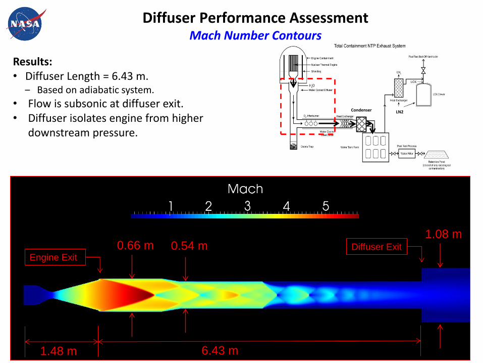
Diffuser Performance Assessment Mach Number Contours
0.66 m 0.54 m 1.08 m
6.43 m
Diffuser Exit Engine Exit
LN2 Condenser
Results: • Diffuser Length = 6.43 m.
‒ Based on adiabatic system.
• Flow is subsonic at diffuser exit. • Diffuser isolates engine from higher
downstream pressure.
1.48 m
12
• Flow is subsonic at diffuser exit
• O2 combustion increases back pressure
on the diffuser.
• Mach Number ~0.15 at O2 injection point
Diffuser Performance Assessment Mach Number Along the Centerline
LN2 Condenser
O2 Injection
Diffuser Exit
Length (m)
Mac
h N
um
ber
NETS 2014
NASA/SSC/EA00
24Feb14 Development of Modeling Approaches for Nuclear Thermal Propulsion Test Facilities - 3028
13
O2 Injection Chemical Composition:
• 99.8% H2
• 0.02% H
Chemical Composition:
• 58.0% H2O
• 16.2% OH
• 15.9% O2
• 6.4% O
• Remainder: H, H2
Note:
Radicals will disappear when the flow is
doused with cooling water.
Diffuser Exit
Diffuser Exit
Engine Exit
Oxygen Injection and Combustion Temperature Contours
NETS 2014
NASA/SSC/EA00
24Feb14 Development of Modeling Approaches for Nuclear Thermal Propulsion Test Facilities - 3028
14
Water Injection and Heat Exchanger Flow Rate Assessment
Total Cooling Water
SSC Flow Rate Limit
Injected Water
Heat Exchanger Coolant Water
Heat Exchanger Analytical
Uncertainty Limit
LN2 Condenser
0
50
100
150
200
250
300
350
0 5 10 15 20 25 30
Co
olin
g W
ate
r Fl
ow
Rat
e (
kgp
m)
Injected Cooling Water/Combustion Exhaust Mass Ratio
Cooling Water Flow Rate Considerations
Concept Baseline Range of Design Possibilities
NETS 2014
NASA/SSC/EA00
24Feb14 Development of Modeling Approaches for Nuclear Thermal Propulsion Test Facilities - 3028
15
0
10
20
30
40
50
60
70
80
90
100
0 5 10 15 20 25 30
Mas
s P
erc
en
tage
(%
)
Injected Cooling Water/Combustion Exhaust Mass Ratio
Residual Composition vs. Cooling Water/Combustion Exhaust Mass Ratio Mass Percentage of H2O(L) Mass Percentage of H2O (Vapor) Mass Percentage of O2 Baseline Design
Cooling Water Injection Steam Condensation
Heat Exchanger
Analytical
Uncertainty Limit
Estimated Water
Storage Limit
Range of Design
Possibilities
Baseline Design Point
Vapor
Liquid
NETS 2014
NASA/SSC/EA00
24Feb14 Development of Modeling Approaches for Nuclear Thermal Propulsion Test Facilities - 3028
16
LN2 Condenser
Task:
• Size water tank to collect exhaust water and external cooling water.
• Determine vent flowrate required to keep tank below 1 psig during loading process.
• Used in-house Rocket Propulsion Test Analysis (RPTA), Fortran-based code to model water collection tank.
‐ 2,800 lbm/sec water flow rate @ 660°R (200°F).
‐ 25% ullage at the end of test.
Results:
• Water tank volume: ~200,000 ft3
• Required vent flowrate: ~ 34.0 lbm/sec.
Water Collection Tank
Pre
ssu
re (
psia
)
-500 500 1500 2500 3500
15.6
15.5
15.4
15.3
15.2
15.1
15.0
14.9
Time (sec)
Water Collection Tank Pressure
NETS 2014
NASA/SSC/EA00
24Feb14 Development of Modeling Approaches for Nuclear Thermal Propulsion Test Facilities - 3028
17
LN2Effluent Heat
Exchanger
O2 InjectionWater
Injection
Summary
• Proof of concept has been analytically demonstrated for an NTP engine test total exhaust containment system; salient features include
‐ Contaminant Storage: ~1.5 million gallons (water), ~165 kgal (LO2)
‐ LH2/LO2/LN2 requirements well within Liquid Rocket Engine supply experience
‐ Low pressure operations: < 60 psi throughout exhaust processing system
NETS 2014
NASA/SSC/EA00
24Feb14 Development of Modeling Approaches for Nuclear Thermal Propulsion Test Facilities - 3028
• Analysis has not identified any significant technical issues with total exhaust containment approach
‐ Preliminary, fully coupled, multi-physics CFD modeling of diffuser and O2 injection performance completed
‐ Effluent transport and storage modeled with validated in-house and commercial facility fluid/thermodynamic codes
18
Forward Plans
FY14
• Complete preliminary concept definition and modeling ‐ Exhaust heat exchanger sizing & operation (Water & LO2 systems) ‐ O2 and water injection system designs ‐ Exhaust debris containment system
• Complete ROM cost estimate of facility for NCPS project effort
FY15 & beyond
• Optimize system design: ‐ O/F ratios for LO2 and water injection ‐ O2 injection location ‐ Exhaust debris containment system
• Subscale demonstration of concept (proposed)
NETS 2014
NASA/SSC/EA00
24Feb14 Development of Modeling Approaches for Nuclear Thermal Propulsion Test Facilities - 3028
19
Development of Modeling Approaches for Nuclear Thermal Propulsion Test Facilities Back-Up Slides
NETS 2014
NASA/SSC/EA00
24Feb14 Development of Modeling Approaches for Nuclear Thermal Propulsion Test Facilities - 3028
20
NASA SSC CFD Capability
• NASA-SSC routinely conducts CFD analysis in support of rocket engine testing.
– multi-species reacting plumes
– propellant feed systems
– cryogenic cavitation
– thermal environments
– blast-wave propagations in test complex
– etc.
Flow Control Devices
Cryogenic Cavitation
Unsteady Feed Systems
Rocket Exhaust Plumes &
Environments
Blast Wave Propagations in Rocket Test Complex
NETS 2014
NASA/SSC/EA00
24Feb14 Development of Modeling Approaches for Nuclear Thermal Propulsion Test Facilities - 3028
21
CRUNCH CFD® Multi-Physics Framework
• CRUNCH CFD® is a multi-physics analysis tool that allows multiple domain-specific flow and heat transfer solvers to be used in a single simulation environment while still allowing efficient communication for time-accurate simulations.
Compressible Module:
Generalized “all-speed” preconditioned density-based solver for perfect gas, imperfect gas, real-fluid multi-phase and combusting flows.
Incompressible Module: Flow solver capable of modeling liquid flows with strong thermal dependency (e.g. cryogens).
Thermal Module: Transient heat conduction solver.
Example Problem: Rocket Conjugate Heat Transfer
• Module 1 - compressible reacting flow solver for plume
• Module 2 - thermal solver for wall conduction
• Module 3 - incompressible flow solver for water cooling channel
NETS 2014
NASA/SSC/EA00
24Feb14 Development of Modeling Approaches for Nuclear Thermal Propulsion Test Facilities - 3028
24Feb14 Development of Modeling Approaches for Nuclear Thermal Propulsion Test Facilities - 3028
23
1.0 1.5 2.0 2.5 3.0
100
80
60
40
20
0
TIME SECONDS Seconds from 155
WinPlot v4.3 b01
11:59:21AM 09/19/2003
Test:Engine:Shutdown:
LDAS2_TPS_E1_M_2476F.winSerial #10.000
JaredTest_37DynVal.WPLunknown200.000
JaredTest_37DynVal.WPL VPOc PCV Position Feedback % SLDAS2_TPS_E1_M_2476F.win PZT10F031 HP LOX Tank 6inchControl Valve Posit %
LDAS2_TPS_E1_M_2476F.win PZY10F03 HP LOX Tank 6inch Control Valve Comm %
• The Rocket Propulsion Test Analysis (RPTA) model is a FORTRAN-based in-house code used to simulate the temporal transient thermodynamic processes of integrated propellant systems.
• Thermodynamic Control Volume Solver Model Accurately Models High-Pressure Cryogenic Fluids and High-Pressure Gaseous Systems. Model Features Include:
– High-Fidelity Pressure Control Valve (PCV) & Closed Loop Control System Model
• RPTA Model Validated Through Test Data Comparisons.
Valve Command
Valve Position • Red = Model • Green = Test Data
A Significant Advantage of the RPTA Model is the Coupling of Control Logic (Electro-Mechanical Process) with Thermodynamic Processes.
Pressure Control Valve (PCV) Model Developed & Validated
Rocket Propulsion Test Analysis (RPTA) Model
NETS 2014
NASA/SSC/EA00
24Feb14 Development of Modeling Approaches for Nuclear Thermal Propulsion Test Facilities - 3028