Issue no. 27 3 O c t o b e r 2006 8 DEVELOPMENT OF NEUTRON AND X-RAY DETECTORS AND NEUTRON RADIOGRAPHY AT BARC A.M. Shaikh Solid State Physics Division Bhabha Atomic Research Centre The author is the recipient of the DAE Technical Excellence Award for the year 2004. A b s t r a c t Design and development of neutron and X-ray detectors and R&D work in Neutron Radiography (NR) for non- destructive evaluation are the important parts of the neutron beam and allied research programme of the Solid State Physics Division (SSPD) of BARC. The detectors fabricated in the division not only meet the in-house requirement of neutron spectrometers but also the need of other divisions in BARC, DAE units and some universities and research institutes in India and abroad for a variety of applications. The NR facility set up by SSPD at Apsara reactor has been used for a variety of applications in nuclear, aerospace, defense and metallurgical industries. The work done in development of neutron and X-ray detectors and Neutron Radiography since 1992 is reported in this article. Neutron and X-ray Detectors Radiation detectors play an important role in medicine, biology, materials science and high-energy physics for monitoring and imaging applications. Gas filled detector, semiconductor detector and scintillation detector are widely used in flux measurement, area monitoring and scattering experiment applications with each of them having their own advantages and limitations. The detector technology is rapidly evolving by making use of recent developments in material processing, new detector designs, data acquisition and analysis systems [1]. In case of neutron scattering experiments the neutron beam intensities are low due to collimation, monochromatisation and scattering. Efficient neutron detection or imaging is therefore essential to use the neutron beam time judicially. Demand for neutron detectors with higher count rates, larger scanning angles and finer position resolutions, is ever increasing. Among the various types of detectors, gas-filled detectors are widely used especially by the neutron scattering communities around the world. Gas-filled position sensitive detectors [2] are conveniently used in various spectrometers to scan large angles as these detectors can be fabricated with large size and show high detection efficiency. They have the advantages of
Transcript
I s s u e n o . 2 7 3 O c t o b e r 2 0 0 68
DEVELOPMENT OF NEUTRON AND X-RAY DETECTORS
AND NEUTRON RADIOGRAPHY
AT BARC
A.M. Shaikh
Solid State Physics Division
Bhabha Atomic Research Centre
The author is the recipient of the DAE Technical ExcellenceAward for the year 2004.
A b s t r a c t
Design and development of neutron and X-ray detectors and R&D work in Neutron Radiography (NR) for non-
destructive evaluation are the important parts of the neutron beam and allied research programme of the
Solid State Physics Division (SSPD) of BARC. The detectors fabricated in the division not only meet the in-house
requirement of neutron spectrometers but also the need of other divisions in BARC, DAE units and some
universities and research institutes in India and abroad for a variety of applications. The NR facility set up by
SSPD at Apsara reactor has been used for a variety of applications in nuclear, aerospace, defense and
metallurgical industries. The work done in development of neutron and X-ray detectors and Neutron
Radiography since 1992 is reported in this article.
Neutron and X-ray Detectors
Radiation detectors play an important role in
medicine, biology, materials science and high-energy
physics for monitoring and imaging applications. Gas
filled detector, semiconductor detector and scintillation
detector are widely used in flux measurement, area
monitoring and scattering experiment applications with
each of them having their own advantages and
limitations. The detector technology is rapidly evolving
by making use of recent developments in material
processing, new detector designs, data acquisition and
analysis systems [1]. In case of neutron scattering
experiments the neutron beam intensities are low due to
collimation, monochromatisation and scattering.
Efficient neutron detection or imaging is therefore
essential to use the neutron beam time judicially. Demand
for neutron detectors with higher count rates, larger
scanning angles and finer position resolutions, is ever
increasing.
Among the various types of detectors, gas-filled detectors
are widely used especially by the neutron scattering
communities around the world. Gas-filled position
sensitive detectors [2] are conveniently used in various
spectrometers to scan large angles as these detectors
can be fabricated with large size and show high detection
efficiency. They have the advantages of
9 I s s u e n o . 2 7 3 O c t o b e r 2 0 0 6
†Detector type nomenclature: the number before alphabet indicates length of detectorin inches and A, B, C, D and E indicate cathode diameter of 0.4”, 0.5”, 1”, 1.5” and 2”
respectively. The anode is made of tungsten wire of 25 mm diameter.Cathode material: brass.
low gamma sensitivity, high neutron efficiency, very high
noiseless internal amplification, no radiation damage,
flexibility of size and fill gas pressure and need simple
counting and pulse processing electronics. Large area
position sensitive detectors with multiwire geometry
developed in 1970s have become widely popular for
many applications [3]. At Solid State Physics Division,
we are involved in indigenous development of gas filled
signal detectors and position sensitive detectors (PSDs)
for X-rays and neutrons for various applications at BARC
and other laboratories in India. These detectors are widely
used as low sensitivity monitor counters to very high
sensitivity signal detectors. Continuous efforts are put in
towards modification of detection techniques to carry
out the experiments efficiently. Various types of detectors
developed are 3He and BF3 filled detectors for neutrons,
linear 1-D single anode PSD, 1-D and 2-D multiwire PSDs,
curvilinear PSD and a microstrip based PSD for both
neutrons and X-rays[4-11]. These detectors show excellent
operational characteristics and stability over the long
periods. Various types of neutron proportional counters
fabricated in our laboratory are listed in Table 1 along
with their specifications and applications. Fig.1 shows
some of these detectors.
Table 2 gives photographs and salient features and
applications of various types of position sensitive detectors
designed, developed and successfully tested in our
laboratory. Many of the 1-D position sensitive neutron
detectors are mounted on the neutron spectrometers at
I s s u e n o . 2 7 3 O c t o b e r 2 0 0 610
Dhruva and working over the years satisfactorily.
The gas filled neutron proportional counters are
extensively used in BARC over a wide range of application
such as flux and area monitoring, spent fuel activity
measurement, study of nuclear reactions, measurement
residual activity of nuclear waste, measurement
of cosmic neutron radiations and
Fig.1: Some of the neutron proportional counters mentioned in Table 1
Table 2: Various types of Position Sensitive Detectors for Neutron and X-rays developed
11 I s s u e n o . 2 7 3 O c t o b e r 2 0 0 6
Table 2 contd...
I s s u e n o . 2 7 3 O c t o b e r 2 0 0 612
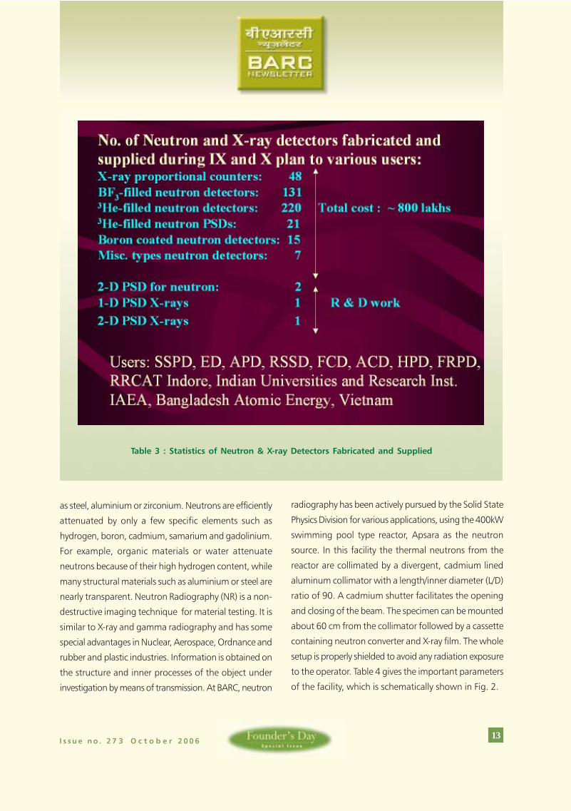
material studies using neutron scattering techniques.
The detectors are also supplied to atomic energy
establishments of other countries like Bangladesh,
Vietnam and Austria ( IAEA). Table 3 gives the statistics
about different types of detectors designed, fabricated
and supplied to various users in BARC and outside
institutions. Users other than BARC can procure these
detectors through the Technolgy Transfer & Collaboration
Division of BARC.
Neutron Radiography Facility and
Applications
The property of thermal neutrons, which makes them
valuable for studying industrial components is their high
penetration through widely used industrial materials such
Table 2 contd...
Table 2 contd...
Table 2 contd...
13 I s s u e n o . 2 7 3 O c t o b e r 2 0 0 6
as steel, aluminium or zirconium. Neutrons are efficiently
attenuated by only a few specific elements such as
hydrogen, boron, cadmium, samarium and gadolinium.
For example, organic materials or water attenuate
neutrons because of their high hydrogen content, while
many structural materials such as aluminium or steel are
nearly transparent. Neutron Radiography (NR) is a non-
destructive imaging technique for material testing. It is
similar to X-ray and gamma radiography and has some
special advantages in Nuclear, Aerospace, Ordnance and
rubber and plastic industries. Information is obtained on
the structure and inner processes of the object under
investigation by means of transmission. At BARC, neutron
radiography has been actively pursued by the Solid State
Physics Division for various applications, using the 400kW
swimming pool type reactor, Apsara as the neutron
source. In this facility the thermal neutrons from the
reactor are collimated by a divergent, cadmium lined
aluminum collimator with a length/inner diameter (L/D)
ratio of 90. A cadmium shutter facilitates the opening
and closing of the beam. The specimen can be mounted
about 60 cm from the collimator followed by a cassette
containing neutron converter and X-ray film. The whole
setup is properly shielded to avoid any radiation exposure
to the operator. Table 4 gives the important parameters
of the facility, which is schematically shown in Fig. 2.
Table 3 : Statistics of Neutron & X-ray Detectors Fabricated and Supplied
I s s u e n o . 2 7 3 O c t o b e r 2 0 0 614
The NR facility of Apsara has been used for a variety of
applications in nuclear, aerospace, defense and
metallurgical industries[12]. The facility has been
extensively used for recording neutron radiographs of
. experimental fuel elements,
. water contamination in marker shell loaded with
phosphorous,
. electric detonators,
Fig. 2 : Schematic of NR Facility at Apsara Reactor
15 I s s u e n o . 2 7 3 O c t o b e r 2 0 0 6
. satellite cable cutters and pyro valves,
. boron-aluminium composites,
. hydride blisters in irradiated zircaloy pressure
tubes,
. variety of hydrogenous and non hydrogenous
materials and
. two phase flows in metallic pipes.
While some of the radiographs are shown in Fig.3, the
most recent work on NR is described in the following
paragraphs.
Assessment of hydriding on
Zircaloy-2/Zr-Nb2.5% pressure tube
material using Neutron
Radiography
One of the most important applications of NR in the
nuclear field is the post irradiation examination of pressure
tube (PT) to check formation of hydride blisters if any. To
ascertain the detection of hydride blisters in zircaloy
pressure tubes, detectability limit of hydride was first
established[13]. For this purpose hydride blisters were
Fig. 3 : Neutron Radiographs of various objects taken with Apsara NR facility.
I s s u e n o . 2 7 3 O c t o b e r 2 0 0 616
created in the laboratory on hydrogen charged Zircaloy
pressure tubes under thermal gradient are examined using
neutron radiography. It was established that a zirconium
hydride blister of nearly 0.25% of job thickness could be
detected using neutron radiography. The theoretical
detectability was also analyzed and found to be in good
agreement with the experimental results. This work served
as reference to examine an irradiated pressure tube from
a power reactor[14,15,16]. Neutron radiographs of an
irradiated pressure tube [Rajasthan Atomic Power Station
(RAPS#2, K-7 position, 8.25 EFPY) sample were recorded
using Apsara NR facility after modifying it for handling
the radioactive zircaloy-2 pressure tube coupons. The PT
sample of size 59mm x 29mm x 4.2mm was radiographed
using transfer technique with 100m thick Dysprosium
converter screen. A PT strip containing four laboratory
generated hydride blisters were also mounted on the
same converter screen cassette to act as a reference.
Fig.4(a) shows neutron radiographs of laboratory
generated hydride blisters in zircaloy-2 and Zr-2.5% Nb
pressure tube coupons where as Fig. 4(b) shows hydride
blister streaks in the zircaloy-2 coupon of the pressure
tube from power reactor RAPS#2. Enlarged view of one
of the blisters is also shown to the right of the figure.
Neutron radiography was also used to study size and
shape of the zirconium hydride blister in the zircaloy-2
pressure tube. Figs. 5(a) and (b) show neutron
radiographs of a pressure tube with three laboratory
generated hydride blisters and with neutron beam incident
parallel and normal to the plane of the blisters
respectively. Fig.5 (a) shows lenticular shape of the blister
with nearly 2/3 of the blister embedded in the wall of
the tube. In the present photograph maximum width of
the blister corresponds to 1.5 mm in 4 mm thick wall of
the pressure tube. However, the smallest blister grown
in the laboratory was found to be mainly on the outer
surface of the pressure tube with almost no penetration